
Panel Mounting Type Indicator REX-AC/DP Series
General Description
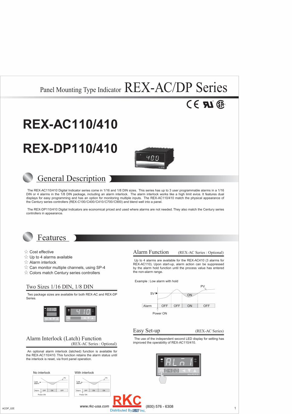
REX-AC110/410
REX-DP110/410
Features
The REX-AC110/410 Digital Indicator series come in 1/16 and 1/8 DIN sizes. This series has up to 3 user programmable alarms in a 1/16DIN or 4 alarms in the 1/8 DIN package, including an alarm interlock. The alarm interlock works like a high limit evice. It features dualdisplays for easy programming and has an option for monitoring multiple inputs. The REX-AC110/410 match the physical appearance ofthe Century series controllers (REX-C100/C400/C410/C700/C900) and blend well into a panel.
The REX-DP110/410 Digital Indicators are economical priced and used where alarms are not needed. They also match the Century seriescontrollers in appearance.
Cost effectiveUp to 4 alarms availableAlarm interlockCan monitor multiple channels, using SP-4Colors match Century series controllers
The use of the independent second LED display for setting hasimproved the operability of REX-AC110/410.
Two package sizes are available for both REX-AC and REX-DPSeries.
Up to 4 alarms are available for the REX-AC410 (3 alarms forREX-AC110). Upon start-up, alarm action can be suppressedby the alarm hold function until the process value has enteredthe non-alarm range.
Two Sizes 1/16 DIN, 1/8 DIN
Alarm Function (REX-AC Series : Optional)
Easy Set-up (REX-AC Series)
An optional alarm interlock (latched) function is available forthe REX-AC110/410. This function retains the alarm status untilthe interlock is reset, via front panel operation.
Alarm Interlock (Latch) Function(REX-AC Series : Optional)
Example : Low alarm with hold
PARA
RKC REX-AC410
PARA
RKC REX-AC410PARA
RKC REX-AC110
Alarm OFF OFFON
Power ON
PV
Alarm OFF ONON
Power ON
PV
Lowalarm
Lowalarm
No interlock With interlock
ONOFFAlarm OFF
SV
Power ON
PV
OFF
ON
1ACDP_02E (800) 576 - 6308www.rkc-usa.comDistributed By Inc,
RKC

Specifications
Input
Performance
General specifications<REX-AC Series>Input a)Thermocouple : K, J, R, S, B, E, T, N (JIS/IEC), PLII (NBS) W5Re/W26Re (ASTM), U, L (DIN) • Influence of external resistance : Approx. 0.4µV/Ω • Input break action : Up-scale b)RTD : Pt100 (JIS/IEC), JPt100 (JIS) • Influence of lead resistance : Approx. less than 10Ω • Input break action : Up-scale c)DC voltage input : 0 to 5V DC, 1 to 5V DC d) DC current input : 0 to 20mA DC, 4 to 20mA DC • Input break action :Down-scaleSampling Time 0.5 secPV Bias Temperature input : -1999 (-199.9) to 9999 (999.9)°C [°F]
DC voltage, DC current: -1999 to 9999 (The decimal point position is same as PV)
<REX-DP Series>Input a)Thermocouple : K, J, R, S, B, E, T, N (JIS/IEC), PLII (NBS) W5Re/W26Re (ASTM), U, L (DIN) • Influence of external resistance : Approx. 0.4µV/Ω • Input break action : Up-scale b)RTD : Pt100 (JIS/IEC), JPt100 (JIS) • Influence of lead resistance : Approx. less than 10Ω • Input break action : Up-scale
Sampling Time 0.5 sec
<REX-AC Series>Measuring Accuracy a) Thermocouple ± (0.5% of PV + 1 digit) or ±3°C (6°F) whichever is larger
•Accuracy is not guaranteed between 0 and 399°C (0 and 799°F) for type R, S and B inputs.
b) RTD ± (0.5% of PV + 1 digit) or ±0.8°C (1.6°F) whichever is larger c) DC voltage and DC current ± (0.5% of span + 1 digit) <REX-DP Series>Measuring Accuracy a) Thermocouple ± (0.5% of PV + 1 digit) or ±3°C (6°F) whichever is larger
•Accuracy is not guaranteed between 0 and 399°C (0 and 799°F) for type R, S and B inputs.
b) RTD ± (0.5% of PV + 1 digit) or ±0.8°C (1.6°F) whichever is larger
<Common spec.>Insulation Resistance More than 20MΩ (500V DC) between measured terminals and ground More than 20MΩ (500V DC) between power terminals and ground
Dielectric Strength 1000V AC for one minute between measured terminals and ground 1500V AC for one minute between power terminals and ground
Alarms (REX-AC series)
<REX-AC Series only>Alarm Function a) Number of alarms: Up to 4 points (Up to 3 points in case of REX-AC110) b) Alarm action : Process (high, low) • Alarm hold function is available. • Alarm interlock is available. c) Alarm differential gap : 0 to 100°C (°F), 0.0 to 100.0°C (°F) or 0.0 to 100.0% of span
Alarm Output Relay output, 250V AC 1A (resistive load), Form A contact
Supply Vltage a) 90 to 264V AC (Including supply voltage variation) [Rating : 100 to 240V AC] (50/60Hz common) b) 21.6 to 26.4V AC (Including supply voltage variation) [Rating : 24V AC] (50/60Hz common) c) 21.6 to 26.4V DC (Ripple rate 10% p-p or less) [Rating : 24V DC]
Power Consumption <REX-AC Series> Less than 10VA (100 to 240V AC) Less than 4.0VA (24V AC) Less than 120mA (24V DC) <REX-DP Series> Less than 6VA (100 to 240V AC) Less than 2.0VA (24V AC) Less than 50mA (24V DC)
Power Failure Effect A power failure of 20msec or less will not affect the action.
Operating Environments : 0 to 50°C [32 to 122°F] , 45 to 85% RH
Memory Backup : Non-volatile memory.
Net Weight REX-AC/DP110 : Approx. 140g REX-AC/DP410 : Approx. 260g
External Dimensions (W x H x D) a) REX-AC/DP110 : 48 x 48 x 100mm b) REX-AC/DP410 : 96 x 48 x 100mm
SP-4 input selector unitInput Thermocouples K, J, R, S, B, E, T, N and RTD Pt100, JPt100 Voltage and Current inputs.
Number of Inputs Thermocouple, voltage/current : 6 points (4 points with transfer switch function) RTD : 3 points (2 points with transfer switch function •SP-4 with transfer switch function is used when more than one SP-4 units are connected.
Display 24VDC of the power supply is required for LED lamps.
Performance of Switch Switching life: 30,000 times (at the operation speed of 70mm/sec). Contact resistance: 15 mΩ (initially), and less than 40Ω after 30,000 switching operations. Switching timing : Non-shooting Switching force: Less than 800g, within ±30% of initial value after 30,000 switching operations.
Operating Environments : 0 to 50°C [32 to 122°F] , 45 to 85% RH
Net Weight Approx. 300g
RKC SP-4
1 2 3 4 5 6
Specifications Model and Suffix CodeModel
Input
Type
TF (Transferswitch) function
SP-4Thermocouple
DC voltage, currentRTD
None
Horizontal typeVertical type
With TF (Transfer switch)
RV
NT
12
CK: K,CJ : J,CR: R,CS : SCB: B,CE: E,CT: T,CN : N
2 ACDP_02E
Model and Suffix Code Table
(Optional)
Panel Mounting Type Indicator REX-AC/DP Series
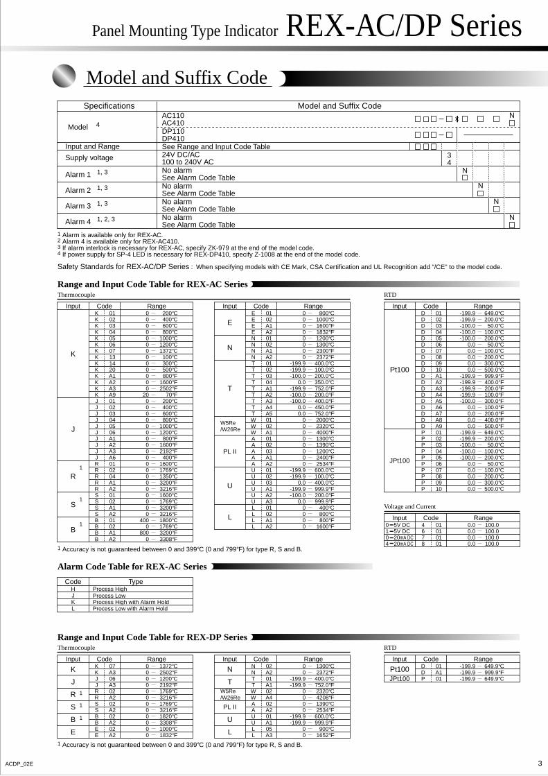
Model and Suffix CodeSpecifications Model and Suffix Code
Model 4
Input and Range
Alarm 2 1, 3
Alarm 1 1, 3
Alarm 3 1, 3
Alarm 4 1, 2, 3
Supply voltage
AC110AC410 DP110 DP410See Range and Input Code Table
No alarmSee Alarm Code Table
No alarmSee Alarm Code TableNo alarmSee Alarm Code TableNo alarmSee Alarm Code Table
24V DC/AC100 to 240V AC
N
N
N
N
N
34
HJKL
Process HighProcess Low
Process Low with Alarm HoldProcess High with Alarm Hold
Alarm Code Table for REX-AC Series
Code Type
Thermocouple RTD
Voltage and Current
Range and Input Code Table for REX-AC Series
0
0
0200°C
1000°C
400°C0
0
600°C
1372°C
0 800°C
0 1200°C
0 100°C0 300°C0 500°C
K
J
R
S
B
Input RangeCode
KK 01
020304050607131420
KKKKKKKK
0
0
0800°F
200°C
1600°F0
0
2502°F
600°C
20 70°F
0 400°C
0 800°C0 1000°C0 1200°C
KK A1
A2A3A9010203040506
KKJJJJJ
0 800°FA1J0 1600°FA2J0 2192°FA3J0 400°FA6J
J
0
0
01600°C
3216°F
1769°C0
0
1350°C
1769°C
0 3200°F
0 1600°C
0 3200°F0 3216°F
400 1800°C
RR 01
0204A1A20102A1A201
RRRSSSS
0 1769°C02B800 3200°FA1B
0 3308°FA2B
B
0
0
0800°C
1200°C
1000°C0
0
1600°F
2300°F
0 1832°F
0 1300°C
0 2372°F-199.9 400.0°C-199.9 100.0°C
T
N
E
W5Re/W26Re
U
PL II
L
Input RangeCode
EE 01
02A1A20102A1A20102
EENNNNTT
-100.0
-100.0
0.0200.0°C
400.0°F
350.0°C-199.9
0.0
752.0°F
752.0°F
-100.0 200.0°F
0.0 450.0°F
0 2000°C0 2320°C0 4000°F
TT 03
04A1A2A3A4A50102A1
TTTTTWW
0 1300°C01A0 1390°C02A0 1200°C03A0 2400°FA1A
W
0
-199.9
-199.92534°F
999.9°F
600.0°C-199.9
0.0
100.0°C
999.9°F
0.0 400.0°C
-100.0 200.0°F
0 400°C0 800°C0 800°F
UA A2
010203A1A2A30102A1
UUUUULL
0 1600°FA2LL
-199.9
-100.0
-199.9649.0°C
200.0°C
200.0°C-100.0
0.0
50.0°C
100.0°C
-100.0 100.0°C
0.0 50.0°C
0.0 200.0°C0.0 300.0°C0.0 500.0°CPt100
JPt100
Input RangeCode
DD 01
020304050607080910
DD
0.00.0
100.0100.0
0.0 100.00.0 100.0
5V DC5V DC20mA DC20mA DC
0104
Input RangeCode
64 01
010101
78
DDDDDD
-199.9
-100.0
-199.9999.9°F
300.0°F
400.0°F-199.9
0.0
200.0°F
200.0°F
-199.9 100.0°F
0.0 100.0°F
0.0 400.0°F0.0 500.0°F
-199.9 649.0°C
DD A1
A2A3A4A5A6A7A8A901
DDDDDDD
-199.9 200.0°C02P-100.0 50.0°C03P-100.0 100.0°C04P-100.0 200.0°C05P
P
0.0
0.0
0.050.0°C
500.0°C
100.0°C0.0 200.0°C0.0 300.0°C
PP 06
07080910
PPP
1 Alarm is available only for REX-AC.2 Alarm 4 is available only for REX-AC410.3 If alarm interlock is necessary for REX-AC, specify ZK-979 at the end of the model code.4 If power supply for SP-4 LED is necessary for REX-DP410, specify Z-1008 at the end of the model code.
1 Accuracy is not guaranteed between 0 and 399°C (0 and 799°F) for type R, S and B.
1 Accuracy is not guaranteed between 0 and 399°C (0 and 799°F) for type R, S and B.
Thermocouple RTD
Range and Input Code Table for REX-DP Series
0
0
01372°C
1769°C
2502°F0
0
1200°C
1769°C
0 2192°F
0 3216°F
0 3216°F0 1820°C0 3308°F
K
J
R
S
B
E
Input RangeCode
KK 07
A306A302A202A202A2
JJRRSSBB
00
1000°C1832°FE
E 02A2
0
0
01300°C
2320°C
2372°F-199.9
0
400.0°C
1390°C
-199.9 752.0°F
0 4208°F
0 2534°F-199.9 600.0°C-199.9 999.9°F
T
N
W5Re/W26Re
U
PL II
L
Input RangeCode
NN 02
A201A102A402A201A1
TTWWAAUU
00
900°C1652°FL
L 05A3
-199.9-199.9
649.9°C999.9°F
-199.9 649.9°C
Pt100JPt100
Input RangeCode
DD 01
A101P
1
1
1
1
1
1
3ACDP_02E
Panel Mounting Type Indicator REX-AC/DP Series
Safety Standards for REX-AC/DP Series : When specifying models with CE Mark, CSA Certification and UL Recognition add "/CE" to the model code.
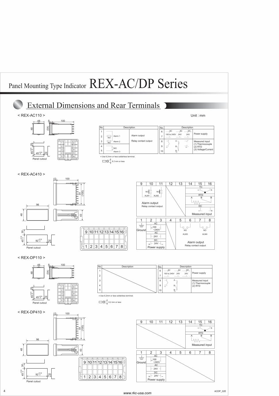
External Dimensions and Rear Terminals
Panel cutout
25
3045
+0.8 0
92+0.8
0
96
48 43
1 2 3 4 5 6 7 8
9 10 11 12 13 14 15 16
12 100
(100
)91
100 to 240V
AC
24V
AC
24V
DC1
2
3
4
5
NO
NO
(1) (3)
DescriptionNo.
Power supply
Alarm 2
Alarm 1
NO
Alarm 3
Alarm output
Relay contact output Measured input(1) Thermocouple(2) RTD(3) Voltage/Current
6
7
8
9
10
DescriptionNo.
(2)B
A
B
48 8 100
4825
2545+0
.6 0
(54)
Panel cutoutUse 6.2mm or less solderless terminal.•
12345
6789
1045+0.6
0
9 10 11 12 13 14 15 16
1 2 3 4 5 6 7 8
100 ~240V
24V
24V
Power supply
Measured input
AC
TC
RTD
DC
AC
DC
A B B
Relay contact output
NO
ALM3
Relay contact output
NO NO
ALM1 ALM2
Alarm output
Ground NO
ALM4
Alarm output
Panel cutout
25
3045
+0.8 0
92+0.8
0
96
48 43
1 2 3 4 5 6 7 8
9 10 11 12 13 14 15 16
12 100
(100
)91
100 to 240V
AC
24V
AC
24V
DC1
2
3
4
5(1)
DescriptionNo.
Power supply
Measured input(1) Thermocouple(2) RTD
6
7
8
9
10
DescriptionNo.
(2)B
A
B
48 8 100
4825
2545+0
.6 0
(54)
Panel cutout 6.2 mm or less
Use 6.2mm or less solderless terminal.•
12345
6789
1045+0.6
0
9 10 11 12 13 14 15 16
1 2 3 4 5 6 7 8
100 ~240V
24V
24V
Power supply
Measured input
AC
TC
RTD
AC
DC
A B B
Ground
< REX-AC110 >
< REX-AC410 >
< REX-DP110 >
< REX-DP410 >
Unit : mm
6.2 mm or less
4 ACDP_02E
Panel Mounting Type Indicator REX-AC/DP Series
www.rkc-usa.com


