
Published in: Fire Safety Journal (2007), vol. 42, iss. 6-7, SEP-OCT, pp. 416-424
Status : Postprint (Author’s version)
Parametric analysis of the lateral-torsional buckling resistance of steel
beams in case of fire
P.M.M. Vila Reala, N. Lopes
a, L. Simões da Silva
b, J.-M. Franssen
c
aDepartment of Civil Engineering, University of Aveiro, 3810 Aveiro, Portugal bDepartment of Civil Engineering, University of Coimbra, 3030-290 Coimbra, Portugal cDepartment of ARGENCO, University of Liege, Liege, Belgium
Abstract
Numerical modelling of the lateral-torsional buckling of steel beams at elevated temperature has shown that the
beam design curve from EN 1993-1-2 is over-conservative in the case of non-uniform bending. Based on the
newly proposed methodology for cold design from the EN 1993-1-1, an improved proposal for the lateral-
torsional buckling of unrestrained steel beams subjected to fire is presented in this paper that addresses the issue
of the influence of the loading type, the steel grade, the pattern of the residual stresses (hot-rolled or welded
sections) and the ratio h/b, between the depth h and the width b of the cross-section on the resistance of the
beam, achieving better agreement with the numerical behaviour while maintaining safety. The proposal is found
to be safe and accurate through an extensive comparison with the results of FEM numerical simulations of more
than 5000 beams. A statistical study of the results is performed, showing the accuracy of the improved proposal
presented in this paper.
Keywords: Steel beams; Lateral-torsional buckling; Fire design; Eurocode 3; Numerical modelling; New
proposal; Residual stresses
Nomenclature
b width of the cross-section
fy yield strength
h depth of the cross-section
ky,θ reduction factor for the yield strength of steel at the steel temperature
θa reached at time t
ky,θ,com reduction factor for the yield strength of steel at the maximum temperature in the compression flange
θa,com reached at time t
kE,θ reduction factor for the slope of the linear elastic range at temperature
θa l length of the beam
Mb,fi,t,Rd lateral-torsional buckling resistance moment of the beam in case of fire
Mcr elastic critical moment for lateral-torsional buckling
Wy appropriate section modulus
plastic section modulus in Γ-axis
elastic section modulus in Γ-axis
Greek letters
α imperfection factor
β severity factor
ΧLT,fi reduction factor for lateral-torsional buckling in the fire design situation
ΓM,fi partial safety factor for the fire situation (usually = 1.0)
non-dimensional slenderness for lateral-torsional buckling at room temperature
non-dimensional slenderness for lateral-torsional buckling at temperature θa
ratio between the moments applied in the extremities
1. Introduction
This paper deals with the question of simple design equations for verification against lateral-torsional buckling
of steel beams under fire conditions. Unrestrained simply supported beams with the rotation along the
longitudinal axis of the beam prevented at the supports—fork supports—are considered here.

Published in: Fire Safety Journal (2007), vol. 42, iss. 6-7, SEP-OCT, pp. 416-424
Status : Postprint (Author’s version)
For beams under fire conditions, the design equation that was present in the ENV version of Eurocode 3 [1]
proved to yield unsafe results, as shown mainly by numerical research work [2,3] confirmed by partial
experimental evidence [4]. A new design equation was thus introduced in the EN version of Eurocode 3 [5]
providing a significant improvement although all research work performed to that stage had considered only the
case of a uniform bending distribution along the members.
For beams at room temperature, significant changes were also introduced from the ENV version [6] to the EN
version [7] of the Eurocode.
At present the equations used in fire situations are different from the ones used at room temperature. The main
differences lie in the fact that, first, non-uniform bending moment distributions are accounted for in a more
comprehensive way at room temperature than at elevated temperature and, second, other factors such as the yield
strength of the material, the shape of the cross-sectional and the pattern of residual stresses are considered at
room temperature whereas they are totally ignored at elevated temperature.
The influence of non-uniform bending moment distributions in the fire condition has been analysed by the
authors [8] who showed that the beneficial effect resulting from reduced plastic zones connected with variable
bending along the beam [9] should also be considered at elevated temperature. If not, the design is much too
conservative for the case of non-uniform bending diagrams [14,15].
The purpose of the present paper is to evaluate the influence of the steel grade (S235-S460) of the cross-sectional
shape and of the pattern of residual stresses (rolled and welded sections) on the lateral-torsional buckling of steel
I-beams under fire conditions. The objective is to see whether it could be worth taking also these parameters into
account when designing a steel beam at elevated temperature.
The study was carried out based on numerical finite element simulations using the specialized finite element
code SAFIR [10], which is a finite element code for geometrical and material non-linear analyses, specially
developed at the University of Liege for studying structures subjected to fire.
For the sake of clarity in the discussions, Table 1 shows the effects that are considered or not in EN 1993-1-1,
EN 1993-1-2, Vila Real et al. [8], and the new proposal presented in this paper.
2. Case study
A simply supported beam with fork supports, as shown in Fig. 1, was chosen to explore the influence of the
various parameters mentioned in the previous section. Regarding the bending moment variation along the
member length, five values (-1, -0.5, 0, 0.5 and 1) of the ψ ratio (see Fig. 1) have been investigated as well as a
uniformly distributed load and a mid-span concentrated load. The influence of the h/b ratio, for both hot-rolled
and welded sections (see Fig. 3), has also been investigated.
A uniform temperature distribution in the cross-section was used so that comparison between the numerical
results and simple design equations is possible. In this paper, the temperatures chosen were 400, 500, 600 and
700 °C, deemed to cover the majority of practical situations.
In the numerical simulations, a lateral geometric imperfection given by the following expression was considered:
where ∕ is the length of the beam.
An initial rotation around the x-axis with a maximum value of l/1000 radians at mid-span was also introduced.
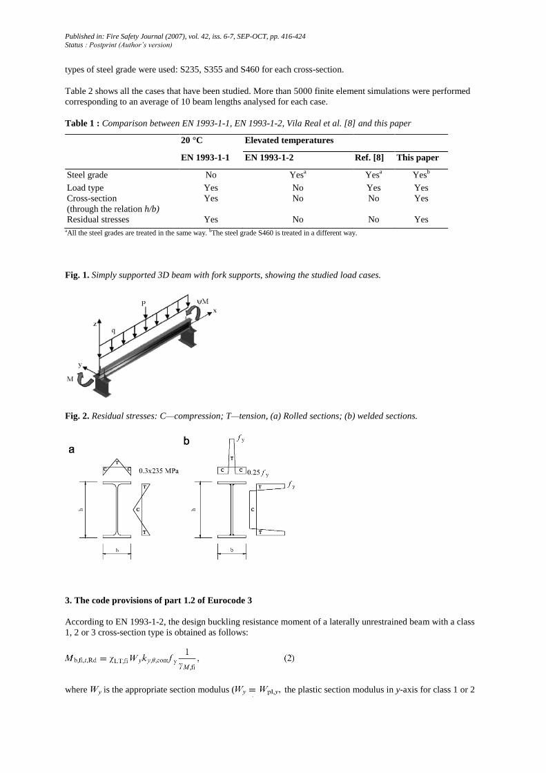
The adopted residual stresses, that present different typical patterns for rolled and welded sections, are
considered as constant across the thickness of the web and flanges. For hot-rolled sections, a triangular
distribution as shown in Fig. 2a, with a maximum value of 0.3 × 235 MPa [11], was chosen. For the welded
sections, the distribution shown in Fig. 2b, that has the maximum value of fy (yield strength) [12], was used.
The following rolled and welded cross-sections were used: IPE 220 steel section (representative of h/b = 2),
HEA 500 steel section (representative of h/b<2) and IPE 500 steel section (representative of h/b > 2). Three
Published in: Fire Safety Journal (2007), vol. 42, iss. 6-7, SEP-OCT, pp. 416-424
Status : Postprint (Author’s version)
types of steel grade were used: S235, S355 and S460 for each cross-section.
Table 2 shows all the cases that have been studied. More than 5000 finite element simulations were performed
corresponding to an average of 10 beam lengths analysed for each case.
Table 1 : Comparison between EN 1993-1-1, EN 1993-1-2, Vila Real et al. [8] and this paper
20 °C Elevated temperatures
EN 1993-1-1 EN 1993-1-2 Ref. [8] This paper
Steel grade No Yesa Yes
a Yes
b
Load type Yes No Yes Yes
Cross-section
(through the relation h/b)
Yes No No Yes
Residual stresses Yes No No Yes aAll the steel grades are treated in the same way. bThe steel grade S460 is treated in a different way.
Fig. 1. Simply supported 3D beam with fork supports, showing the studied load cases.
Fig. 2. Residual stresses: C—compression; T—tension, (a) Rolled sections; (b) welded sections.
3. The code provisions of part 1.2 of Eurocode 3
According to EN 1993-1-2, the design buckling resistance moment of a laterally unrestrained beam with a class
1, 2 or 3 cross-section type is obtained as follows:
where is the appropriate section modulus ( the plastic section modulus in y-axis for class 1 or 2

Published in: Fire Safety Journal (2007), vol. 42, iss. 6-7, SEP-OCT, pp. 416-424
Status : Postprint (Author’s version)
cross-sections, or the elastic section modulus in y-axis for class 3 cross-sections), denotes
the reduction factor for the yield strength of steel at the maximum temperature in the compression flange
reached at time t and is the reduction factor formally based on the Maquoi-Rondal formula, detailed
derivations being found in Ref. [13] and given by

Published in: Fire Safety Journal (2007), vol. 42, iss. 6-7, SEP-OCT, pp. 416-424
Status : Postprint (Author’s version)
Table 2 Case studied
High temperatures (400, 500, 600 and 700 °C)
Hot-rolled beams subjected to LTB Welded beams subjected to LTB
φ = 1 φ = 0.5 ψ = 0 φ = -0.5 ψ = -1 Point load Distrib. load φ = 1 φ = 0.5 ψ = 0 φ = -0.5 ψ = -1 Point load Distrib. load
HEA500 S235 S355 S460
IPE220 S235 S355 S460
IPE500 S235 S355 S460

Published in: Fire Safety Journal (2007), vol. 42, iss. 6-7, SEP-OCT, pp. 416-424
Status : Postprint (Author’s version)
with
The non-dimensional slenderness (or , if the temperature field in the cross-section is uniform) is
given by
where kE,θ is the reduction factor for the slope of the linear elastic range at the steel temperature θa reached at
time t and is the non-dimensional slenderness for lateral-torsional buckling at room temperature given by
where Mcr is the elastic critical moment for lateral-torsional buckling.
The imperfection factor α is a function of the steel grade and is given by
This proposal was based on research work [2,3] on the behaviour of the European hot-rolled profile IPE 220 in
steel grades S235 and S355 submitted to uniform bending (see Figs. 3a and b).
In the next paragraphs, the influence of the steel grade, of the type of the cross-section, of the pattern of the
residual stresses (hot-rolled or welded section) and finally of the shape of the bending diagrams will be examined
and the results compared to the formulae from EN 1993-1-2.
3.1. The influence of the steel grade
To show here the influence of the steel grade, an IPE 220 profile has been considered submitted to a uniform
bending moment diagram (ψ = 1). Fig. 3 shows that the EC3 proposal is in good agreement with the numerical
results for the steel grades S235 and S355, see Figs. 3a and b.
However, for the steel grade S460 the beam design curve should go down slightly, in the intermediate range of
the non-dimensional slenderness, to ensure a similar level of accuracy as for the other two steel grades, see Fig.
3c.
3.2. The influence of the cross-section
To study the influence of the type of the cross-section, an IPE 220 steel section (representative of h/b = 2), an
HEA 500 steel section (representative of h/b < 2) and an IPE 500 steel section (representative of h/b > 2) were
chosen.
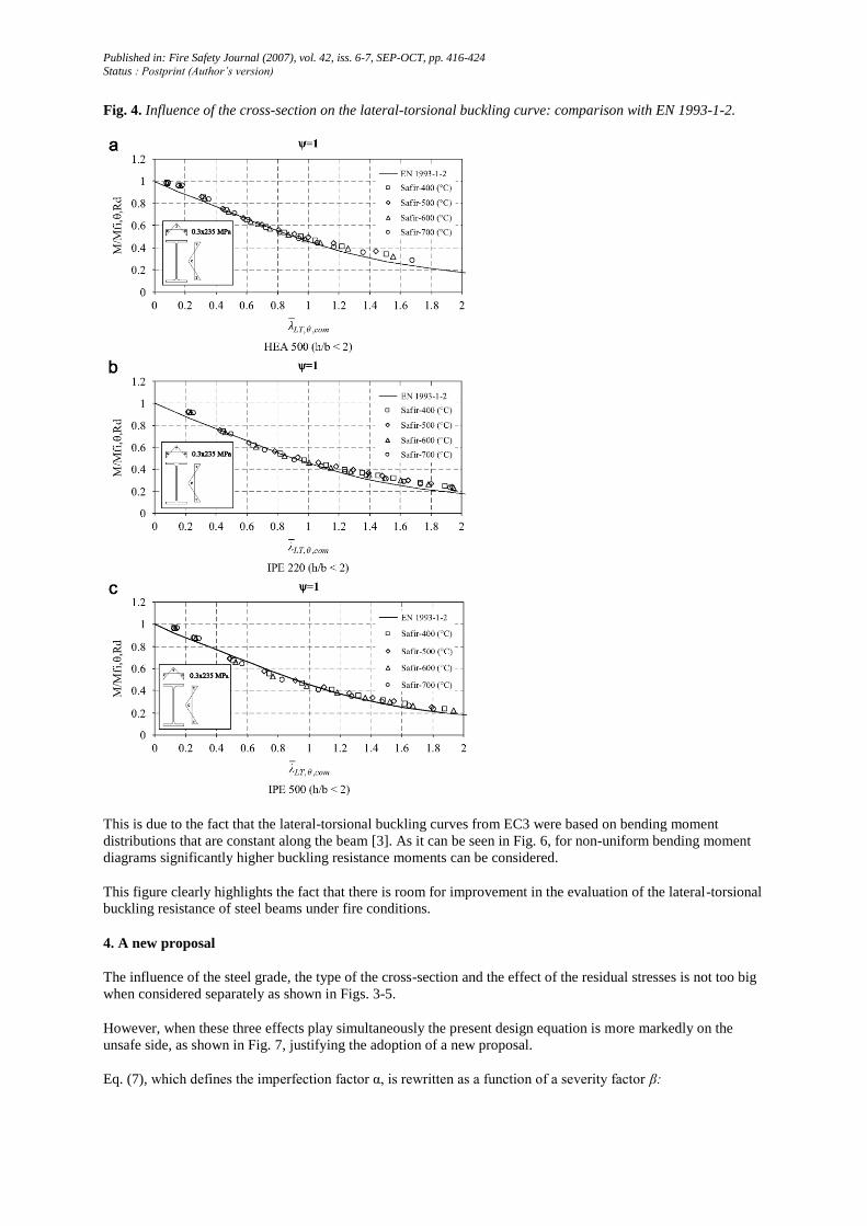
Fig. 4 compares the EC3 proposal with the numerical results for the three cross-sections for the case of uniform
bending (ψ = 1) and for the steel grade S235.
This figure shows that as the h/b ratio of the cross-section increases, the beam design curve should go down to
ensure a similar level of accuracy.

Published in: Fire Safety Journal (2007), vol. 42, iss. 6-7, SEP-OCT, pp. 416-424
Status : Postprint (Author’s version)
3.3. The influence of the residual stresses (hot-rolled or welded sections)
To analyse the influence of the residual stresses, the proposal of the EC3 was compared with the numerical
results obtained for a hot-rolled and a welded section which exhibit different patterns of residual stresses as
shown in Fig. 2.
Fig. 5 compares the EC3 proposal with the numerical results for a hot-rolled and a welded HEA 500 profile in
steel grade S355 submitted to uniform bending diagrams (ψ = 1)∙
This figure shows that for the welded section the beam design curve of the EC3 proposal should go down
slightly to ensure the same degree of accuracy as for the hot-rolled section.
3.4. The influence of the applied loads
The influence of the shape of the bending diagram shown in Fig. 6 has already been studied previously [8]. As
shown in this figure, for the case of non-uniform bending, i.e. for values of the ψ ratio equal to -1 and 0, Eqs. (2)-
(7) lead to over-conservative results when compared to the numerical results (here illustrated for an IPE 220 of
steel grade S235).
Fig. 3. Beam design curve from EN 1993-1-2: comparison with numerical results for IPE 220.
Published in: Fire Safety Journal (2007), vol. 42, iss. 6-7, SEP-OCT, pp. 416-424
Status : Postprint (Author’s version)
Fig. 4. Influence of the cross-section on the lateral-torsional buckling curve: comparison with EN 1993-1-2.
This is due to the fact that the lateral-torsional buckling curves from EC3 were based on bending moment
distributions that are constant along the beam [3]. As it can be seen in Fig. 6, for non-uniform bending moment
diagrams significantly higher buckling resistance moments can be considered.
This figure clearly highlights the fact that there is room for improvement in the evaluation of the lateral-torsional
buckling resistance of steel beams under fire conditions.
4. A new proposal
The influence of the steel grade, the type of the cross-section and the effect of the residual stresses is not too big
when considered separately as shown in Figs. 3-5.
However, when these three effects play simultaneously the present design equation is more markedly on the
unsafe side, as shown in Fig. 7, justifying the adoption of a new proposal.
Eq. (7), which defines the imperfection factor α, is rewritten as a function of a severity factor β:

Published in: Fire Safety Journal (2007), vol. 42, iss. 6-7, SEP-OCT, pp. 416-424
Status : Postprint (Author’s version)
The severity factor β is given in Table 3. This factor was calibrated through an extensive comparison with the
results of FEM numerical simulations.
To take into account the moment distribution between the lateral restraints of members, the authors have already
proposed [8] a modified reduction factor given by
where
and kc is a correction factor according to Table 4, established by numerical adjustment to match as closely as
possible a representative sample of finite element numerical results. The accuracy of this new proposal is shown
in the next section.
Fig. 5. Influence of the residual stresses on the lateral-torsional buckling curve for the HEA 500: comparison
with EN 1993-1-2.
5. Accuracy of the proposal
In this section, the new proposal is validated for different cross-sections, different load cases, different steel
grades and different residual stresses (hot-rolled sections and welded sections).
5.1. Numerical validation
The beam design curve from part 1-2 of the Eurocode 3 is denoted here as "EN 1993-1-2", and the curve
obtained adopting the new factor ƒ and the severity factor as it is defined in Table 3 is denoted as "new

Published in: Fire Safety Journal (2007), vol. 42, iss. 6-7, SEP-OCT, pp. 416-424
Status : Postprint (Author’s version)
proposal".
As it is impossible to show in the paper all the comparisons made according to Table 2, only the welded section
equivalent to the IPE 500, representative of h/b>2, in steel grade S460, for all the studied load cases, is shown in
Fig. 8.
Fig. 6. Influence of the applied load on the lateral-torsional buckling: comparison with EN 1993-1-2.
5.2. Statistical evaluation
The values of the severity factor β defined in the Table 3 were chosen so that the new proposal has the same
degree of accuracy as the formulae of the EN 1993-1-2 for a hot-rolled IPE 220 submitted to uniform bending
[2,3].
For each chosen severity factor, it is possible to evaluate the ratio between the analytical value of the ultimate
design lateral-torsional buckling resistance moment, and the corresponding SAFIR moment. This
ratio is also the ratio between the analytical and the SAFIR lateral-torsional buckling coefficient as follows:

Published in: Fire Safety Journal (2007), vol. 42, iss. 6-7, SEP-OCT, pp. 416-424
Status : Postprint (Author’s version)
The proposal is safe if it leads to values of xi lower then 1, and unsafe for values higher than 1 (see Figs. 12 and
13).
The average value, µ, and the standard deviation, σ, were calculated as
where n is the total number of the numerical simulations.
Fig. 7. Numerical results for a welded IPE 500 in steel grade S460: comparison with EN 1993-1-2.
Table 3: Values of the severity factor, β
Cross-section Limits β
S235, S275, S355, S420 S460
Rolled I section h/b<2
h/b>2
0.65
0.75
0.70
0.80
Welded I section h/b≤2
h/b>2
0.70
0.80
0.75
0.85
Other cross-sections - 0.80 0.85
Table 4 : Correction factors kc for the new proposal
Moment distribution Class 1, 2, 3 sections
kc
0.6 +0.3ψ + 0.15ψ2 but kc<l
-1≤ψ≤1
0.79
0.91
Note: For other bending diagrams kc = 1.

Published in: Fire Safety Journal (2007), vol. 42, iss. 6-7, SEP-OCT, pp. 416-424
Status : Postprint (Author’s version)
Fig. 8. Numerical results for a welded IPE 500 of steel grade S460 at high temperatures for all load cases
studied.
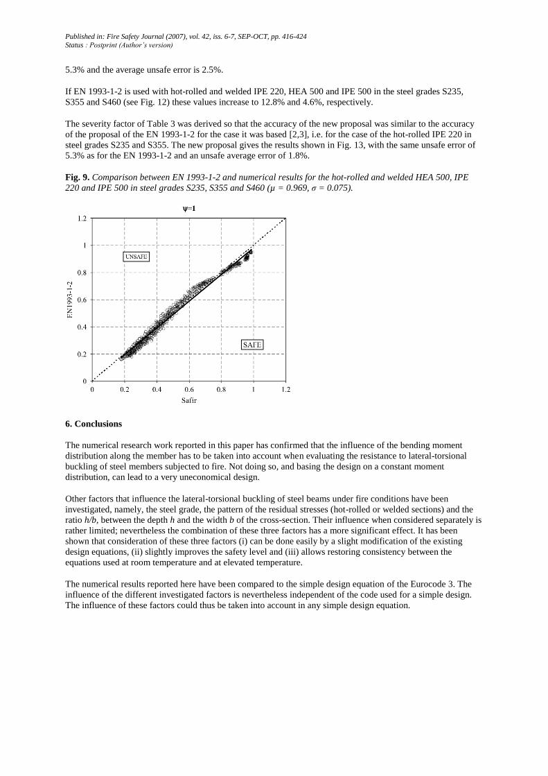
The results obtained with EN 1993-1-2 for both hot-rolled and welded IPE 220 steel section (representative of h/
b = 2), HEA 500 steel section (representative of h/b<2) and IPE 500 steel section (representative of h/b > 2) in
steel grades S235, S355 and S460 are shown in Fig. 9. The average value and the standard deviation are,
respectively, µ = 0.969 and σ = 0.075. If the new proposal is used with hot-rolled and welded IPE 220, HEA 500
and IPE 500 in steel grades S235, S355 and S460 (see Fig. 10) the average value and the standard deviation take
the values µ= 0.943 and σ = 0.066, respectively, showing that the new proposal is safer than the EC3 with a
smaller value of the standard deviationFig. 11 shows the ratio xi when EN 1993-1-2 is used with the hot-rolled
IPE 220 in steel grades S235 and S355 submitted to uniform bending moment. The maximum unsafe error is
Published in: Fire Safety Journal (2007), vol. 42, iss. 6-7, SEP-OCT, pp. 416-424
Status : Postprint (Author’s version)
5.3% and the average unsafe error is 2.5%.
If EN 1993-1-2 is used with hot-rolled and welded IPE 220, HEA 500 and IPE 500 in the steel grades S235,
S355 and S460 (see Fig. 12) these values increase to 12.8% and 4.6%, respectively.
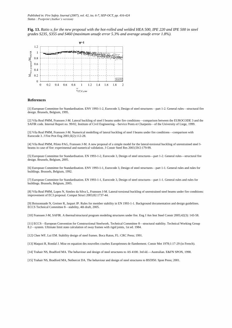
The severity factor of Table 3 was derived so that the accuracy of the new proposal was similar to the accuracy
of the proposal of the EN 1993-1-2 for the case it was based [2,3], i.e. for the case of the hot-rolled IPE 220 in
steel grades S235 and S355. The new proposal gives the results shown in Fig. 13, with the same unsafe error of
5.3% as for the EN 1993-1-2 and an unsafe average error of 1.8%.
Fig. 9. Comparison between EN 1993-1-2 and numerical results for the hot-rolled and welded HEA 500, IPE
220 and IPE 500 in steel grades S235, S355 and S460 (µ = 0.969, σ = 0.075).
6. Conclusions
The numerical research work reported in this paper has confirmed that the influence of the bending moment
distribution along the member has to be taken into account when evaluating the resistance to lateral-torsional
buckling of steel members subjected to fire. Not doing so, and basing the design on a constant moment
distribution, can lead to a very uneconomical design.
Other factors that influence the lateral-torsional buckling of steel beams under fire conditions have been
investigated, namely, the steel grade, the pattern of the residual stresses (hot-rolled or welded sections) and the
ratio h/b, between the depth h and the width b of the cross-section. Their influence when considered separately is
rather limited; nevertheless the combination of these three factors has a more significant effect. It has been
shown that consideration of these three factors (i) can be done easily by a slight modification of the existing
design equations, (ii) slightly improves the safety level and (iii) allows restoring consistency between the
equations used at room temperature and at elevated temperature.
The numerical results reported here have been compared to the simple design equation of the Eurocode 3. The
influence of the different investigated factors is nevertheless independent of the code used for a simple design.
The influence of these factors could thus be taken into account in any simple design equation.

Published in: Fire Safety Journal (2007), vol. 42, iss. 6-7, SEP-OCT, pp. 416-424
Status : Postprint (Author’s version)
Fig. 10. Comparison between the new proposal and numerical results for the hot-rolled and welded HEA 500,
IPE 220 and IPE 500 in steel grades S235, S355 and S460 (µ = 0.943 and σ = 0.066).
Fig. 11. Ratio xi for EN 1993-1-2 with hot-rolled IPE 220 in steel grades S235 and S355 (maximum unsafe error
5.3% and average unsafe error 2.5%).
Fig. 12. Ratio x, for EN 1993-1-2 with the hot-rolled and welded HEA 500, IPE 220 and IPE 500 in steel grades
S235, S355 and S460 (maximum unsafe error 12.8% and average unsafe error 4.6%).
Published in: Fire Safety Journal (2007), vol. 42, iss. 6-7, SEP-OCT, pp. 416-424
Status : Postprint (Author’s version)
Fig. 13. Ratio xi for the new proposal with the hot-rolled and welded HEA 500, IPE 220 and IPE 500 in steel
grades S235, S355 and S460 (maximum unsafe error 5.3% and average unsafe error 1.8%).
References
[1] European Committee for Standardisation. ENV 1993-1-2, Eurocode 3, Design of steel structures—part 1-2. General rules—structural fire design. Brussels, Belgium, 1995.
[2] Vila Real PMM, Franssen J-M. Lateral buckling of steel I beams under fire conditions—comparison between the EUROCODE 3 and the
SAFIR code. Internal Report no. 99/02, Institute of Civil Engineering—Service Ponts et Charpents—of the University of Liege, 1999.
[3] Vila Real PMM, Franssen J-M. Numerical modelling of lateral buckling of steel I beams under fire conditions—comparison with
Eurocode 3. J Fire Prot Eng 2001;ll(2):112-28.
[4] Vila Real PMM, Piloto PAG, Franssen J-M. A new proposal of a simple model for the lateral-torsional buckling of unrestrained steel I-beams in case of fire: experimental and numerical validation. J Constr Steel Res 2003;59/2:179-99.
[5] European Committee for Standardisation. EN 1993-1-2, Eurocode 3, Design of steel structures—part 1-2. General rules—structural fire
design. Brussels, Belgium, 2005.
[6] European Committee for Standardisation. ENV 1993-1-1, Eurocode 3, Design of steel structures—part 1-1. General rules and rules for
buildings. Brussels, Belgium, 1992.
[7] European Committee for Standardisation. EN 1993-1-1, Eurocode 3, Design of steel structures—part 1-1. General rules and rules for buildings. Brussels, Belgium, 2005.
[8] Vila Real PMM, Lopes N, Simões da Silva L, Franssen J-M. Lateral-torsional buckling of unrestrained steel beams under fire conditions:
improvement of EC3 proposal. Comput Struct 2003;82:1737-44.
[9] Boissonnade N, Greiner R, Jaspart JP. Rules for member stability in EN 1993-1-1. Background documentation and design guidelines.
ECCS Technical Committee 8—stability, 4th draft, 2005.
[10] Franssen J-M, SAFIR. A thermal/structural program modeling structures under fire. Eng J Am Inst Steel Constr 2005;42(3): 143-58.
[11] ECCS—European Convention for Constructional Steelwork. Technical Committee 8—structural stability. Technical Working Group
8.2—system. Ultimate limit state calculation of sway frames with rigid joints, 1st ed. 1984.
[12] Chen WF, Lui EM. Stability design of steel frames. Boca Raton, FL: CRC Press; 1991.
[13] Maquoi R, Rondal J. Mise en equation des nouvelles courbes Européennes de flambement. Constr Met 1978;1:17-29 (in French).
[14] Trahair NS, Bradford MA. The behaviour and design of steel structures to AS 4100. 3rd éd.—Australian. E&FN SPON, 1998.
[15] Trahair NS, Bradford MA, Nethercot DA. The behaviour and design of steel structures to BS5950. Spon Press; 2001.


