

Partial Scan Design with Guaranteed Partial Scan Design with Guaranteed Combinational ATPGCombinational ATPG
Vishwani D. AgrawalVishwani D. AgrawalAgere Systems, Circuits and Systems Research LabAgere Systems, Circuits and Systems Research Lab
Murray Hill, NJ 07974, USAMurray Hill, NJ 07974, USA
[email protected]@agere.com
Yong C. Kim and Kewal K. SalujaYong C. Kim and Kewal K. SalujaUniversity of Wisconsin, Dept. of ECEUniversity of Wisconsin, Dept. of ECE
Madison, WI 53706, USAMadison, WI 53706, USA
[email protected]@ece.wisc.eduedu and and [email protected]@engr.wisc.edu

Partial scan with comb. ATPG 2Aug. 21, 2001
OverviewOverview
1. Problem statement1. Problem statement
2. Background and previous work2. Background and previous work
3. Combinational ATPG for general acyclic circuits3. Combinational ATPG for general acyclic circuits Balanced model generationBalanced model generation Test generation – multiple-fault modelTest generation – multiple-fault model Results Results
4. Special classes of acyclic circuits4. Special classes of acyclic circuits Internally balanced structureInternally balanced structure Balanced structureBalanced structure Strongly balanced structureStrongly balanced structure Results Results
5. Conclusion5. Conclusion

Partial scan with comb. ATPG 3Aug. 21, 2001
Problem StatementProblem Statement Partial scan design has less DFT overhead, but Partial scan design has less DFT overhead, but
is less desirable than full-scan because it is less desirable than full-scan because it requires sequential ATPGrequires sequential ATPG
Problem: To devise a combinational ATPG Problem: To devise a combinational ATPG method for general acyclic circuits; cyclic method for general acyclic circuits; cyclic structures can be made acyclic by partial scanstructures can be made acyclic by partial scan
FF1
FF2 FF2
A cyclic circuit Acyclic partial scan circuit
Partial scan with comb. ATPG 4Aug. 21, 2001
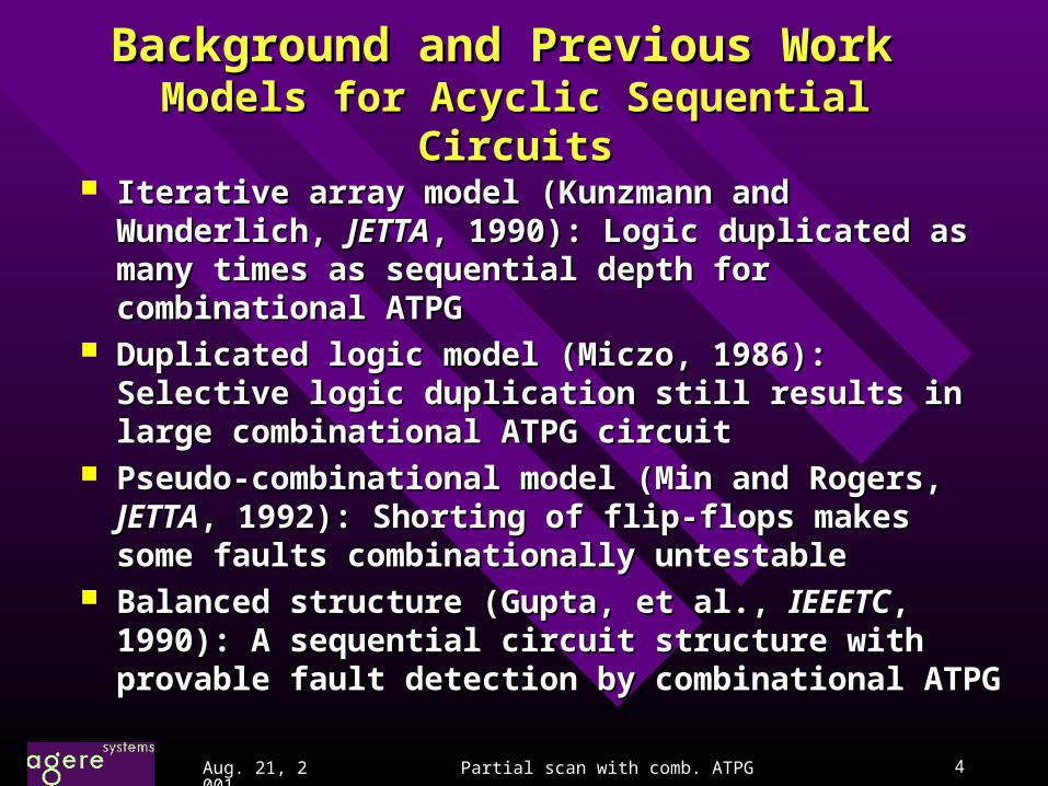
Background and Previous Work Background and Previous Work Models for Acyclic Sequential CircuitsModels for Acyclic Sequential Circuits
Iterative array model (Kunzmann and Wunderlich, Iterative array model (Kunzmann and Wunderlich, JETTAJETTA, 1990): Logic duplicated as many times as , 1990): Logic duplicated as many times as sequential depth for combinational ATPG sequential depth for combinational ATPG
Duplicated logic model (Miczo, 1986): Selective logic Duplicated logic model (Miczo, 1986): Selective logic duplication still results in large combinational ATPG duplication still results in large combinational ATPG circuitcircuit
Pseudo-combinational model (Min and Rogers, Pseudo-combinational model (Min and Rogers, JETTAJETTA, 1992): Shorting of flip-flops makes some , 1992): Shorting of flip-flops makes some faults combinationally untestablefaults combinationally untestable
Balanced structure (Gupta, et al., Balanced structure (Gupta, et al., IEEETCIEEETC, 1990): A , 1990): A sequential circuit structure with provable fault sequential circuit structure with provable fault detection by combinational ATPGdetection by combinational ATPG

Partial scan with comb. ATPG 5Aug. 21, 2001
Relevant ResultsRelevant Results
Theorem (Bushnell and Agrawal, 2000): A Theorem (Bushnell and Agrawal, 2000): A test for a testable non-flip-flop fault in a test for a testable non-flip-flop fault in a cycle-free (acyclic) circuit can always be cycle-free (acyclic) circuit can always be found with at most found with at most ddseqseq+1 time-frames.+1 time-frames.
Balanced circuit (Gupta, et al., Balanced circuit (Gupta, et al., IEEETCIEEETC, , 1990): An acyclic circuit is called balanced 1990): An acyclic circuit is called balanced if all paths between any pair of nodes have if all paths between any pair of nodes have the same sequential depth. A test for any the same sequential depth. A test for any testable fault in a balanced circuit can be testable fault in a balanced circuit can be found by combinational ATPG.found by combinational ATPG.
Partial scan with comb. ATPG 6Aug. 21, 2001
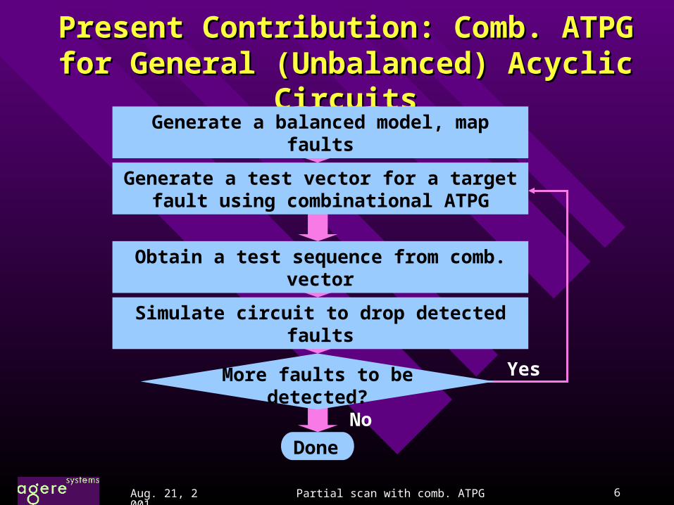
Present Contribution: Comb. ATPG for Present Contribution: Comb. ATPG for General (Unbalanced) Acyclic CircuitsGeneral (Unbalanced) Acyclic Circuits
Generate a balanced model, map faults
Done
No
Generate a test vector for a target fault using combinational ATPG
Obtain a test sequence from comb. vector
Simulate circuit to drop detected faults
More faults to be detected?
Yes

Partial scan with comb. ATPG 7Aug. 21, 2001
An ExampleAn Example
FF
Unbalanced nodes
s-a-0
FF replaced by buffer
s-a-0
s-a-0
a
b
a0
b0
a-1
b-1
Balanced
model
0
X
1
1
Combinational
vector
0
1/0 1/0
11/0
Test sequence: 11, 0X
dseq = 1

Partial scan with comb. ATPG 8Aug. 21, 2001
A Single Fault Model for a Multiple FaultA Single Fault Model for a Multiple Fault((NewNew))
s-a-1
A
B
C
b
c
a
An equivalent single stuck-at fault: output of AND gate stuck-at 1Multiple stuck-at fault: lines a and b stuck-at 1 and line c stuck-at 0.
A
B
C
b
c
a
s-a-1
s-a-1
s-a-0
Partial scan with comb. ATPG 9Aug. 21, 2001
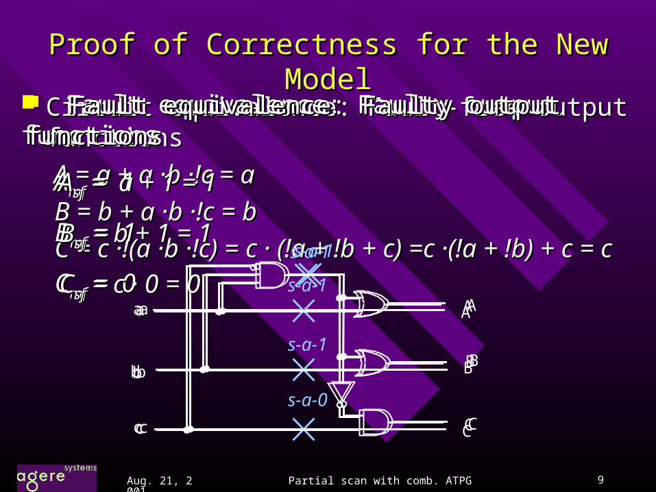
Proof of Correctness for the New ModelProof of Correctness for the New Model Circuit equivalence: Fault-free output functionsCircuit equivalence: Fault-free output functions
A = a + a A = a + a ··bb · ·!c = a!c = a
B = b + a B = b + a ··bb · ·!c = b!c = b
C = c C = c ··!(a !(a ··bb · ·!c) = c !c) = c ·· (!a (!a + !+ !bb + + c) =c c) =c ··(!a (!a + !+ !b) + c = cb) + c = cs-a-1
A
B
C
b
c
a A
B
C
b
c
a
s-a-1
s-a-1
s-a-0
Fault equivalence: Faulty output functionsFault equivalence: Faulty output functions
AAmfmf = 1 = 1
BBmfmf = 1 = 1
CCmfmf = 0 = 0
Fault equivalence: Faulty output functionsFault equivalence: Faulty output functions
AAsfsf = a = a + + 1 = 11 = 1
BBsfsf = b = b ++ 1 = 1 1 = 1
CCsfsf = c = c ·· 0 = 0 0 = 0 s-a-1
A
B
C
b
c
a

Partial scan with comb. ATPG 10Aug. 21, 2001
6
2
5
43
X7FF2
1 D QA
B
D Q
C
FF1
D Q
D Q
FF3
FF4Y
D QFF21
0
6
2
5
43
X7FF2
1 D Q
D QFF1
D Q
D Q
FF3
FF4Y
D QFF21
0
1
0
1
ATF=1
BTF=1
ATF=0
BTF=0
BTF=2
C
Acyclic Circuit Combinational ATPG Acyclic Circuit Combinational ATPG ExampleExample
6
2
5
43
X7FF2
1 D Q
D QFF1
D Q
D Q
FF3
FF4Y
D QFF21
0
1
0
1
ATF=1
BTF=1
ATF=0
BTF=0
CTF=1
BTF=2
CTF=2
6
2
5
43
X7FF2
1 D QA
B
D Q
C
FF1
D Q
D Q
FF3
FF4Y
Multiple fault mapping: A stuck-at fault of 1 is mapped onto a multiple fault
6
2
5
43
X7FF21
FF1
FF3
FF4 Y
FF21
0
1
0
1
A
B
A
B
C
B
C

Partial scan with comb. ATPG 11Aug. 21, 2001
ISCAS ’89 Benchmark Circuit Result: ISCAS ’89 Benchmark Circuit Result: S5378S5378
Circuit statisticsCircuit statisticsNumber of gates: 2,781Number of gates: 2,781Number of FFs: 179Number of FFs: 179Number of faults: 4,603Number of faults: 4,603
S5378 Original Full-scan
Partial-scan (seq.)
Partial-scan (comb.)
Scan-FFs 0 179 30 30 Overhead 0 % 25.8 % 4.3 % 4.3 % Fault Eff. 70.9 % 100.0 % 99.7 % 99.7 % ATPG Time 5,533 s* 5 s* 1,268 s* 23 s*
* * Sun Ultra Sparc work stationSun Ultra Sparc work station

Partial scan with comb. ATPG 12Aug. 21, 2001
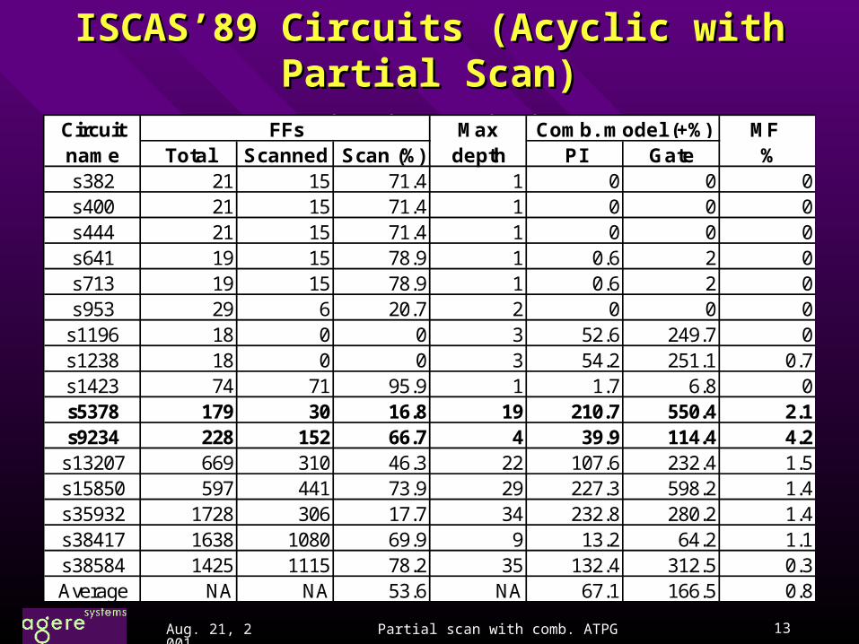
ISCAS’89 Circuits (Acyclic with Partial Scan)ISCAS’89 Circuits (Acyclic with Partial Scan) FC: cov. (%), FC: efficiency (%), VL: vec. Length, TGT: CPU s Sun Ultra FC: cov. (%), FC: efficiency (%), VL: vec. Length, TGT: CPU s Sun Ultra
CircuitName FC FE VL TGT (s) FC FE VL TGT (s)s382 100.00 100.00 81 0.1 100.00 100.00 86 0.0s400 98.50 100.00 83 0.1 98.50 100.00 89 0.0s444 97.52 100.00 77 0.1 97.52 100.00 78 0.1s641 100.00 100.00 112 0.2 100.00 100.00 123 0.1s713 94.88 100.00 118 0.9 94.88 100.00 126 0.3s953 100.00 100.00 182 0.4 100.00 100.00 190 0.1s1196 99.87 100.00 304 1.0 99.87 100.00 380 0.5s1238 96.64 100.00 327 2.1 96.64 100.00 398 1.1s1423 99.08 100.00 182 1.3 99.08 100.00 182 0.5s5378 93.69 99.71 1117 1268.0 93.69 99.71 1230 23.3s9234 93.16 99.94 1233 426.0 93.16 99.94 1680 85.7
s13207 97.13 99.97 2442 1008.0 97.13 99.97 3126 55.0s15850 96.65 99.97 2507 856.0 96.66 99.97 5780 140.8s35932 89.80 100.00 2377 569.0 89.80 100.00 7548 79.4s38417 99.25 99.54 5360 861.0 99.25 99.55 8632 98.2s38584 95.45 99.95 5763 7293.0 95.46 99.96 12231 239.6
Sequential ATPG Combinational ATPG
Partial scan with comb. ATPG 13Aug. 21, 2001
ISCAS’89 Circuits (Acyclic with Partial Scan)ISCAS’89 Circuits (Acyclic with Partial Scan) Circuit statisticsCircuit statistics
Circuit Max MF name Total Scanned Scan (%) depth PI Gate %s382 21 15 71.4 1 0 0 0s400 21 15 71.4 1 0 0 0s444 21 15 71.4 1 0 0 0s641 19 15 78.9 1 0.6 2 0s713 19 15 78.9 1 0.6 2 0s953 29 6 20.7 2 0 0 0
s1196 18 0 0 3 52.6 249.7 0s1238 18 0 0 3 54.2 251.1 0.7s1423 74 71 95.9 1 1.7 6.8 0s5378 179 30 16.8 19 210.7 550.4 2.1s9234 228 152 66.7 4 39.9 114.4 4.2
s13207 669 310 46.3 22 107.6 232.4 1.5s15850 597 441 73.9 29 227.3 598.2 1.4s35932 1728 306 17.7 34 232.8 280.2 1.4s38417 1638 1080 69.9 9 13.2 64.2 1.1s38584 1425 1115 78.2 35 132.4 312.5 0.3Average NA NA 53.6 NA 67.1 166.5 0.8
Comb. model (+%)FFs

Partial scan with comb. ATPG 14Aug. 21, 2001
Acyclic
Subclasses of Acyclic CircuitsSubclasses of Acyclic Circuits
Internally balanced (IB) circuit: A circuit that becomes Internally balanced (IB) circuit: A circuit that becomes balancedbalanced by splitting of PI fanouts (Fujiwara by splitting of PI fanouts (Fujiwara et al., IEEETC, et al., IEEETC, 2000)2000)
Acyclic circuit:Acyclic circuit: A sequential circuit without feedbackA sequential circuit without feedback
Balanced (B) circuit: A circuit in which all paths between Balanced (B) circuit: A circuit in which all paths between any pair of nodes (PIs, POs, gates or FFs) have the same any pair of nodes (PIs, POs, gates or FFs) have the same sequential depth (Gupta sequential depth (Gupta et al, IEEETC, et al, IEEETC, 1990)1990)
Strongly Strongly balanced (SB) circuit: A balanced circuit which has same depth from any PIs to any reachable POs (Balakrishnan and Chakradhar, VLSI Design `96)
Combinational circuit: A sequential circuit with Combinational circuit: A sequential circuit with full-scanfull-scan
Sequential
IB SBB
Combinational

Partial scan with comb. ATPG 15Aug. 21, 2001
Number of Scan FFs for Various SubclassesNumber of Scan FFs for Various Subclasses
Circuits Total FFs Acyclic IB B SB Comb.s5378 179 30 91 96 163 179s9234 228 152 201 209 220 228
s13207 669 310 420 451 542 669s15850 597 438 529 534 563 597s35932 1728 306 1728 1728 1728 1728s38417 1636 1115 1224 1232 1476 1636s38584 1452 1115 1431 1431 1447 1452Total 6729 3618 5809 5866 6336 6729
Wt. Avg. N/A 53.8% 86.3% 87.2% 94.2% 100.0%
IB: Internally balanced (Fujiwara, IEEETC, 2000)
B: Balanced (Gupta, et al., IEEETC, 1990)
SB: Strongly balanced (Balakrishnan and Chakradhar, VLSI Design ’96)
Partial scan with comb. ATPG 16Aug. 21, 2001
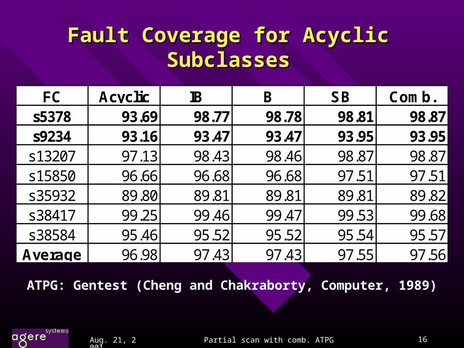
Fault Coverage for Acyclic SubclassesFault Coverage for Acyclic Subclasses
FC Acyclic IB B SB Comb.s5378 93.69 98.77 98.78 98.81 98.87s9234 93.16 93.47 93.47 93.95 93.95
s13207 97.13 98.43 98.46 98.87 98.87s15850 96.66 96.68 96.68 97.51 97.51s35932 89.80 89.81 89.81 89.81 89.82s38417 99.25 99.46 99.47 99.53 99.68s38584 95.46 95.52 95.52 95.54 95.57
Average 96.98 97.43 97.43 97.55 97.56
ATPG: Gentest (Cheng and Chakraborty, Computer, 1989)

Partial scan with comb. ATPG 17Aug. 21, 2001
ATPG CPU Seconds for Acyclic SubclassesATPG CPU Seconds for Acyclic Subclasses(Sun Ultra Workstation) (Sun Ultra Workstation)
Circuit Acyclic IB B SB Comb.s5378 23.3 0.6 0.6 0.4 0.2s9234 85.7 66.7 64.6 64.6 64.6
s13207 55.0 21.8 20.0 26.5 26.5s15850 140.8 115.6 113.7 113.2 112.3s35932 79.4 70.1 70.0 70.8 70.8s38417 98.2 24.2 24.2 24.8 24.8s38584 239.6 30.1 30.2 28.9 28.0
Average 103.1 47.0 46.2 47.0 46.8
ATPG: Gentest (Cheng and Chakraborty, Computer, 1989)

Partial scan with comb. ATPG 18Aug. 21, 2001
Comb. And Sequential Vector LengthsComb. And Sequential Vector Lengths
Name VL CC VL CC VL CC VL CC VL CCs5378 1,230 37k 912 83k 912 88k 580 95k 580 104ks9234 1,680 256k 1,138 236k 1,138 238k 727 161k 766 175ks13207 3,126 970k 2,328 1040k 2,328 1051k 1,238 673k 1,355 909ks15850 5,780 2533k 1,785 946k 1,785 955k 1,192 673k 1,192 713ks35932 7,548 2311k 2,319 4012k 2,319 4012k 2,320 4014k 2,319 4012ks38417 8,632 9628k 4,863 7143k 4,863 7168k 3,329 4918k 3,384 5541ks38584 12,231 13641k 7,722 11055k 7,722 11055k 3,645 5279k 3,627 5271k
VL: Number of combinational ATPG vectors
CC: Sequential test clock cycles for scan sequences
Acyclic Balanced Internally bal. Strongly bal. Combinational
Partial scan with comb. ATPG 19Aug. 21, 2001
ConclusionConclusion
Using a balanced circuit model and combinational Using a balanced circuit model and combinational ATPG, we can generate tests for any acyclic ATPG, we can generate tests for any acyclic sequential circuit with equal or higher fault coverage sequential circuit with equal or higher fault coverage and efficiency than obtained by sequential ATPG.and efficiency than obtained by sequential ATPG.
For acyclic circuits, the new ATPG procedure For acyclic circuits, the new ATPG procedure provides comparable fault coverage and provides comparable fault coverage and efficiency with significantly lower DFT ( partial-efficiency with significantly lower DFT ( partial-scan) overhead as compared to internally scan) overhead as compared to internally balanced, balanced, strongly balanced and balanced, balanced, strongly balanced and combinational subclasses. combinational subclasses.

Partial scan with comb. ATPG 20Aug. 21, 2001
Thank you


