

PATTERNLESS EDGER
Model LE-9000SX
OPERATOR’S MANUAL

NIDEK CO., LTD. : 34-14, Maehama, Hiroishi-cho, Gamagori, Aichi 443-0038, Japan
(Manufacturer) Telephone: (81-533) 67-6611
Facsimile: (81-533) 67-6610
NIDEK CO., LTD : 3F Sumitomo Fudosan Hongo Bldg., 3-22-5, Hongo,
(Tokyo Office) Bunkyo-Ku, Tokyo 113-0033, Japan
Telephone: (81-3) 5844-2641
Facsimile: (81-3) 5844-2642
NIDEK INCORPORATED : 47651 Westinghouse Drive, Fremont, California 94539, U. S. A.
(United States Agent) Telephone: (510) 226-5700
Facsimile: (510) 226-5750
NIDEK SOCIETE ANONYME : Europarc 13, rue Auguste Perret, 94042 CRETEIL, France
(Authorized Representative) Telephone: (01) 49 80 97 97
Facsimile: (01) 49 80 32 08
September 200640341-P902K
Printed in JAPAN

BEFORE USE OR MAINTENANCE, READ THIS MANUAL.
This Operator’s Manual contains information necessary for the operation of the NIDEK
PATTERNLESS EDGER Model LE-9000SX Type PC, Type PL4, Type PLB, and Type
PLB-2R.
This manual provides operating procedures, cautions for safety, specifications,
accessories, and maintenance. IEC and UL standards are applied in this manual. For
correct use, this manual is needed. Especially, cautions for safety and operating
procedures must be thoroughly understood before using the instrument.
Keep this manual handy to verify use.
If you encounter any problems or have questions about the instrument during use, please
contact NIDEK or your authorized distributor.

Table of Contents
§1 INTRODUCTION ........................................................................................................ 1-1
1.1 Outline of the Product ................................................................................................. 1-1
1.2 Symbol Information .................................................................................................... 1-2
§2 SAFETY ......................................................................................................................... 2-1
2.1 Cautions during Use ................................................................................................... 2-1
2.2 Storage ...................................................................................................................... 2-3
2.3 Transport ................................................................................................................... 2-3
2.4 Installation .................................................................................................................. 2-4
2.5 Wiring ........................................................................................................................ 2-5
2.6 After Use ................................................................................................................... 2-5
2.7 Maintenance and Check ............................................................................................. 2-5
2.8 Disposal ..................................................................................................................... 2-7
2.9 Labels ........................................................................................................................ 2-8
2.10 Safety Function ...................................................................................................... 2-10
§3 CONFIGURATION ...................................................................................................... 3-1
§4 OPERATING PROCEDURES .................................................................................... 4-1
4.1 Operation Flow......................................................................................................... 4-1
4.2 Preparation ............................................................................................................... 4-3
4.3 Tracings .................................................................................................................... 4-4
4.3.1 Tracing frames ................................................................................................. 4-4
4.3.1.1 Tracing both rims ................................................................................. 4-4
4.3.1.2 Tracing single rims ................................................................................. 4-5
4.3.1.3 Semiauto tracing .................................................................................... 4-5
4.3.1.4 Tracing goggle type frames .................................................................... 4-6
4.3.2 Tracing patterns ................................................................................................. 4-7
4.3.3 Tracing dummy lenses ........................................................................................ 4-8
4.3.4 Tracing during processing ................................................................................ 4-10
4.3.5 Stopping tracing .............................................................................................. 4-10
4.3.5.1 Stopping frame tracing ......................................................................... 4-10
4.3.5.2 Stopping pattern or dummy lens tracing ................................................ 4-10
4.4 Layouts .................................................................................................................... 4-11
4.4.1 Selecting processing conditions and inputting layout data .................................. 4-11
4.4.2 Inputting height from lens outline ...................................................................... 4-14
4.4.2.1 Layout of bifocal lens .......................................................................... 4-15
4.4.2.2 Layout of progressive power lens ........................................................ 4-16
4.4.3 Eye point layout .............................................................................................. 4-17
Page

4.5 Blocking Lenses ....................................................................................................... 4-18
4.5.1 Blocking in active mode ................................................................................... 4-18
4.5.1.1 Blocking progressive power lenses ...................................................... 4-18
4.5.2 Blocking in passive mode ................................................................................ 4-19
4.5.3 Blocking bifocal lenses .................................................................................... 4-20
4.6 Processings .............................................................................................................. 4-21
4.6.1 Beveling .......................................................................................................... 4-21
4.6.1.1 Auto processing mode ......................................................................... 4-22
4.6.1.2 Guided processing mode ..................................................................... 4-25
4.6.1.3 Guided processing mode (tilting function) ............................................. 4-29
4.6.1.4 EX lens processing mode .................................................................... 4-32
4.6.2 Flat (rimless) edging ........................................................................................ 4-36
4.6.2.1 Flat (rimless) edging mode ................................................................... 4-36
4.6.2.2 EX lens flat (rimless) edging mode ....................................................... 4-39
4.6.2.3 Auto grooving mode ............................................................................ 4-41
4.6.2.4 Guided grooving mode ........................................................................ 4-43
4.6.2.5 EX lens grooving mode ....................................................................... 4-47
4.6.3 Other processings ........................................................................................... 4-50
4.6.3.1 Processing for frame changing .............................................................. 4-50
4.6.3.2 Processing half-eye lenses ................................................................... 4-53
4.6.3.3 Polishing (Type PL4, PLB, and PLB-2R) ............................................ 4-56
4.6.3.4 Chamfering ......................................................................................... 4-57
4.6.3.5 Glass soft processing ........................................................................... 4-58
4.6.3.6 Inputting the frame tilt angle in flat edging .............................................. 4-59
4.7 Checking the Lens Size ............................................................................................. 4-60
4.7.1 Checking the lens size ...................................................................................... 4-60
4.7.2 Retouching lenses ............................................................................................ 4-60
4.8 Processing the Opposite Lens ................................................................................... 4-62
4.9 Removing the Lens Cup............................................................................................ 4-62
4.10 Treatment after Daily Use ....................................................................................... 4-63
4.11 Daily Checks .......................................................................................................... 4-64
4.11.1 Daily check before use .................................................................................. 4-64
4.11.2 Daily check after use ..................................................................................... 4-65
4.12 Periodical Check .................................................................................................... 4-66
§5 OTHER FUNCTIONS .................................................................................................. 5-1
5.1 Process Counter ........................................................................................................ 5-1
5.2 Parameter Settings .................................................................................................... 5-2
5.3 Storing Initial Display ............................................................................................... 5-7
Page

5.4 Storing and Calling Up the Traced Data ...................................................................... 5-8
5.4.1 When the edger is not connected to the barcode scanner .................................... 5-9
5.4.2 When the edger is connected to the barcode scanner ....................................... 5-10
§6 TROUBLESHOOTING GUIDE ................................................................................. 6-1
§7 STORAGE .................................................................................................................... 7-1
§8 MAINTENANCE .......................................................................................................... 8-1
8.1 Wheel Dressing ......................................................................................................... 8-1
8.2 Replacing the Water and Filter (115 V regions) ........................................................... 8-5
8.2.1 Replacing the water (when the optional FP-100 is equipped) .............................. 8-5
8.2.2 Replacing the water (when the optional FP-100 is not equipped) ........................ 8-8
8.3 Replacing the Water and Filter (230 V regions) ......................................................... 8-10
8.4 Replacing Fuses ....................................................................................................... 8-12
8.5 Cleaning the Exterior ................................................................................................ 8-12
8.6 Size Adjustment ........................................................................................................ 8-13
8.7 Adjusting Bevel Position ........................................................................................... 8-14
8.8 Adjusting Axis Shift ................................................................................................... 8-16
8.8.1 Adjusting axis shift when polishing is not done .................................................. 8-16
8.9 Adjusting Lens Margin Allowed for Finishing ............................................................. 8-18
8.10 PD Adjustment ....................................................................................................... 8-19
8.11 Adjustment for Polishing.......................................................................................... 8-20
8.11.1 If a part of edge is left unpolished (Type PL4, PLB, and PLB-2R) .................. 8-20
8.11.2 If the front edge or rear edge is left unpolished (Type PLB and PLB-2R) ....... 8-23
8.11.3 Axis shift adjustment for polishing (Type PL4, PLB, and PLB-2R) .................. 8-24
8.12 Adjustment for Grooving......................................................................................... 8-26
8.12.1 Setting of initial value for depth and width ....................................................... 8-26
8.12.2 Adjusting groove position .............................................................................. 8-27
8.12.3 Adjusting groove depth .................................................................................. 8-28
8.12.3.1 Groove depth is not made as designated ............................................ 8-28
8.12.3.2 Groove depth is not even ................................................................... 8-29
8.13 Adjustment for Chamfering ..................................................................................... 8-31
8.13.1 Setting of SFB mode and chamfering amount ................................................. 8-31
8.13.2 Adjusting chamfering amount ......................................................................... 8-32
8.13.2.1 Safety bevel is not made as designated ............................................... 8-32
8.13.2.2 Chamfering amount is not even .......................................................... 8-34
8.14 Tracer Calibration................................................................................................... 8-35
8.15 List of Consumable Articles .................................................................................... 8-36
Page
§9 SPECIFICATIONS ....................................................................................................... 9-1
§10ACCESSORIES .......................................................................................................... 10-1
10.1 NIDEK-type Accessories ...................................................................................... 10-1
10.2 WECO-type Accessories ...................................................................................... 10-1
10.3 SANTI-type Accessories ...................................................................................... 10-2
APPENDIX A. SUPPLEMENT .............................................................................................. A-1
A.1 Selection of Tracing ................................................................................................ A-1
A.2 Selection of Layout ................................................................................................. A-3
A.3 Selection of Blocking .............................................................................................. A-4
A.4 Selection of Processing ........................................................................................... A-5
APPENDIX B. ERROR CODE .............................................................................................. B-1
APPENDIX C. GLOSSARY ................................................................................................... C-1
Page


1.1 Outline of the Product
This instrument is a fully-automatic lens edger which reads the lens outline of eyeglasses directly
from frames and processes a lens into the shape of frames.
This edger has a processing unit at the center front, a control panel for the processing unit at the
front, a display panel at the right front, a tracing unit, and a control panel for the tracing unit at the
upper side. The tracing unit measures the frame shape, the display panel presents the traced
outline and the lens layout, and the processing unit processes a lens into the desired shape.
Several kinds of processing wheels are provided in the processing unit, and therefore, this instrument
selects the most suitable wheels and the processing sequences according to the lens material to be
processed.
[Lens materials and processing modes]
: Processing is available.
× : Processing is not available.
: Processing is available (except for glass lenses).
§1INTRODUCTION
PlasticHigh index
plastic
Polycar-
bonateGlass
Acrylic
resinBeveling
Flat
edgingGrooving Polishing
Chamf-
ering
PC ×
PL4flat
edging
only
PLB ×
PLB-2R
Lens material Processing mode
Type

1 - 2
1.2 Symbol Information
This symbol on the body indicates that caution should be taken. It is necessary to refer to
Operator’s Manual before using the instrument.
This symbol means caution for electric shock. The inside of the instrument includes high-
voltage circuit. Do not take off the cover.
This symbol on the power switch indicates that the power is ON.
This symbol on the power switch indicates that the power is OFF.
This symbol indicates the contrast adjustment.
This symbol means the fuse rating.
This symbol indicates that the instrument must be supplied only with alternating current.
This symbol indicates the date of manufacture.
This symbol indicates the manufacturer.
This symbol indicates that this product shall be disposed of in a separate collection of electrical
and electronic equipment in EU.

§2SAFETY
In this manual, Signal Words are used to designate a degree or level of safety alerting,
whose definitions are as follows.
WARNING: Indicates a potentially hazardous situation which, if not avoided,
could result in death or serious injury.
CAUTION: Indicates a potentially hazardous situation which, if not avoided,
may result in minor or moderate injury or property damage accident.
Some items described in CAUTION, however, may cause a serious accident. Follow
all the instructions mentioned below since they are very important.
2.1 Cautions during Use
WARNING
• Never touch the processing wheel when it is turning.
Injury may occur.
• Be sure to keep the soundproof cover closed during processing.
Spray including processing waste may cause eye damage.
• Should abnormal conditions such as cracks or bare areas on the processing wheel have been
found, stop using the instrument immediately and contact NIDEK or your authorized distributor.
Continued use of the instrument may cause the wheel to break and scatter, causing injury.
• Release the chuck by pressing after making sure that the wheels have come to a complete
stop.
If the chuck is released before the wheels have stopped completely and a lens is dropped, it
may contact the turning wheels and its scattering may cause injury.
• Be sure to use this instrument only to process eyeglass lenses.
If this instrument processes any other materials, the processing wheels may be damaged and
cannot perform normal processing. Moreover, the wheels may break and broken pieces may
injure personnel.
2 - 2
CAUTION
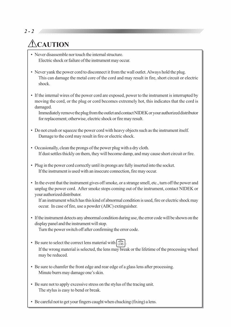
• Never disassemble nor touch the internal structure.
Electric shock or failure of the instrument may occur.
• Never yank the power cord to disconnect it from the wall outlet. Always hold the plug.
This can damage the metal core of the cord and may result in fire, short circuit or electric
shock.
• If the internal wires of the power cord are exposed, power to the instrument is interrupted by
moving the cord, or the plug or cord becomes extremely hot, this indicates that the cord is
damaged.
Immediately remove the plug from the outlet and contact NIDEK or your authorized distributor
for replacement; otherwise, electric shock or fire may result.
• Do not crush or squeeze the power cord with heavy objects such as the instrument itself.
Damage to the cord may result in fire or electric shock.
• Occasionally, clean the prongs of the power plug with a dry cloth.
If dust settles thickly on them, they will become damp, and may cause short circuit or fire.
• Plug in the power cord correctly until its prongs are fully inserted into the socket.
If the instrument is used with an insecure connection, fire may occur.
• In the event that the instrument gives off smoke, or a strange smell, etc., turn off the power and
unplug the power cord. After smoke stops coming out of the instrument, contact NIDEK or
your authorized distributor.
If an instrument which has this kind of abnormal condition is used, fire or electric shock may
occur. In case of fire, use a powder (ABC) extinguisher.
• If the instrument detects any abnormal condition during use, the error code will be shown on the
display panel and the instrument will stop.
Turn the power switch off after confirming the error code.
• Be sure to select the correct lens material with .
If the wrong material is selected, the lens may break or the lifetime of the processing wheel
may be reduced.
• Be sure to chamfer the front edge and rear edge of a glass lens after processing.
Minute burrs may damage one’s skin.
• Be sure not to apply excessive stress on the stylus of the tracing unit.
The stylus is easy to bend or break.
• Be careful not to get your fingers caught when chucking (fixing) a lens.

2 - 3
(A) (B)
CAUTION
• When removing the leap cup with the cup remover, hold the lens through the soft cloth.
If you hold the lens with bare hands, the lens edge may hurt your hands.
• Be sure to confirm that wash water (for the inside wall of the processing chamber) and cooling
water (for the wheels) flow properly.
If water does not flow, lenses are not processed properly and the edger may be damaged.
2.2 Storage
CAUTION
• Do not store the instrument where it may get wet or where poisonous gases or liquids are
present.
• Maintain the instrument under the following conditions at transport or storage (packed).
Conditions Temperature: –25ºC - 70ºC
Humidity: 10% - 100%
Pressure: 700 hPa - 1060 hPa
2.3 Transport
CAUTION
• When moving the instrument, ask for assistance.
Moving the instrument may cause back injury or injury by falling.
• When moving the instrument, hold (A) and (B) for both of the right and left sides. Be
sure not to hold the cover. Only hold the metal part of the underside.
The instrument may be dropped by holding
the cover only and it may cause injury and
malfunction.
• When putting the instrument down, be
careful not to get your fingers caught.
Fingers may get caught between the cabinet
and instrument injuring them.
• Use the specified packing material when transporting the instrument to lessen the damage if
dropped.
Excessive vibration or shock to the instrument may cause instrument malfunction.

2 - 4
510
180 153
322
40
14
0
42
5
47
0
Opening A
Position of stage foot (4spots)
(Measure: mm)
30
50
Opening B
2.4 Installation
CAUTION
• Use the instrument under the following conditions.
- A dust free environment
- A stable place with no tilt
- A vibration and shock free environment
• Install the instrument where it can be used at the following temperature and humidity.
Use conditions Temperature: 5ºC - 40ºC
Humidity: Relative humidity does not exceed 50% at a
maximum temperature of 40ºC.
Pressure: 700 hPa - 1060 hPa
• Install the instrument in a location that provides the operation area specified on p. 2-6.
• Install the instrument on the specified table (option) or a stage which is strong enough for the
instrument weight (42 kg).
Vibrations and noises may produce, or normal processings may not be performed.
• Use a stage whose size is larger than the
measurements of the figure to the right. Also
set the adjuster at the foot of the stage so that
the stage can be adjusted without tilt or play.
It is necessary to make openings in the top to
draw the pipe and cord through.
Opening A: For power cord of pump
Opening B: For feedwater pipe and drain pipe
• Do not install the instrument in a place exposed to direct sunlight or a place where the temperature
and humidity are high.
• Install the instrument where the pollutions such as corrosive gases, acids, and salts are not
present.
Corrosion or malfunction of the instrument may occur.
• Be sure to leave 3 cm or more of space to the rear so that the fan will not be blocked.
If the fan is blocked, it will rise the temperature of the inside of the instrument and it
may cause malfunction.

2 - 5
2.5 Wiring
CAUTION
• Do not overload one electrical outlet.
Abnormal heat generation may occur at the outlet in conjunction with the other devices.
• Be sure to use the socket which meets the power specifications.
If the line voltage is too high or low, the instrument may not perform properly. Malfunction or
fire also may occur.
• Be sure to ground the instrument.
Electric shock or fire may occur in the event of failure or electric leakage.
2.6 After Use
CAUTION
• If the instrument will not be used for a long time, unplug the power plug from the wall
outlet.
If a thick layer of dust settles on the pins of the plug, it will become damp, and short circuit or
fire may occur.
• Clean the processing unit after each use of the day. Be sure to clean it on the day that the
instrument is used.
If it is left for several days after use, the processing wastes become settled and hard to remove.
• Turn the power switch OFF and keep the tracing unit cover and soundproof cover closed
when the instrument is not in use.
If dust settles, it may affect the measurement accuracy or cause malfunction.
2.7 Maintenance and Check
CAUTION
• Be sure to perform the starting inspection before use and finishing inspection after use. It
is recommended to have a periodical inspection every two years.
The periodical inspection is performed by a service person. Contact NIDEK or your
authorized distributor.
• Be sure to keep an enough space (see p. 2-6.) for maintenance.
Working in a tight place may cause possible injury.

2 - 6
Approx. 500mm
Maintenance
Operation area
area
Approx. 500mm
Approx. 500mm
Approx. 485mm
Approx. 500mm
Approx. 1000mm
Approx. 520mm
CAUTION
• Be sure to use the specified fuses for replacement.
If not, fire may occur.
• Be sure to use the suitable dressing stick for wheel dressing.
If not, the wheel may be damaged and normal processing cannot be done.
• Be sure to replace the dressing stick worn in some 4 cm with a new one.
It is hard to hold the shorten dressing stick, and hand injury may occur.
• Be sure to wear protective glasses for wheel dressing.
Spray including processing wastes may cause eye damage.
• Never dress the roughing wheel for plastic lenses.
The wheel may be damaged.
• In dressing mode, the cover sensor is released and the wheels turn with the soundproof cover
open. While dressing, work with the special care.
[Operation area/ Maintenance area]
2 - 7
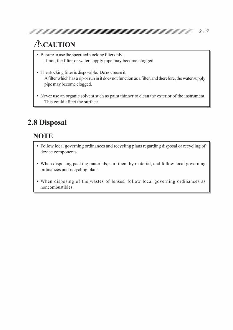
CAUTION
• Be sure to use the specified stocking filter only.
If not, the filter or water supply pipe may become clogged.
• The stocking filter is disposable. Do not reuse it.
A filter which has a rip or run in it does not function as a filter, and therefore, the water supply
pipe may become clogged.
• Never use an organic solvent such as paint thinner to clean the exterior of the instrument.
This could affect the surface.
2.8 Disposal
NOTE
• Follow local governing ordinances and recycling plans regarding disposal or recycling of
device components.
• When disposing packing materials, sort them by material, and follow local governing
ordinances and recycling plans.
• When disposing of the wastes of lenses, follow local governing ordinances as
noncombustibles.

2 - 8
2.9 Labels
The following labels provide safety information about each part.
<Front view>
<Rear view>
or
or
(115 V regions only)

2 - 9
<Top view>
or
or

2 - 10
2.10 Safety Function
For safety use, various functions are provided.
[Soundproof cover check function at the start of processing]
Lens processing does not start unless the soundproof cover is closed.
CAUTION
• If the soundproof cover is opened during processing, the instrument does not stop. Be sure not
to open the soundproof cover during processing since it is hazardous.
Besides, open the soundproof cover only after making sure that the wheels have come to a
complete stop.
[Stop key]
This is the key to stop processing. Processing can be stopped immediately using this key under
abnormal conditions. Turn the power switch OFF if necessary. To restart processing after processing
has stopped, press .
[Self-check function]
Operation conditions are checked all the time by this function. If something unusual occurred
in the instrument, the system will immediately stop and display the error number which
indicates the error content on the display panel.

2 - 11

[Whole system]
[Rear side of the main body]
RS-232C interface connector
Connector for barcode scanner
Outlet for pump 1
Outlet for pump 2
Power switch
Contrast control
Inlet
Cooling fan
Table
Tracing unit cover
Display panel
Control panel
for tracing unit
Control panel
for processing unit
Drawer
§3CONFIGURATION
Soundproof cover

3 - 2
Soundproof cover
Prevents water and processing wastes from
splashing, and it blocks processing sound.
The processing unit is contained under this
cover.
The cover must keep closed during pro-
cessing.
Table
This is a special table for the instrument,
in which the feedwater pump and tank can
be stored.
The drain pipe and feedwater pipes are
connected to the main body through the
opening of the table.
Contrast control
Adjusts the contrast of the display panel.
Turn the control according to its use envi-
ronment to clear the screen.
RS-232C interface connector
This is a connector to communicate with
an external computer.
This connector conforms to RS-232C
interface. The optional quick pattern
tracer can also be connected.
Connector for barcode scanner
This is a connector to which the optional
barcode scanner (or numeric keypad) is
connected.
Outlet for pump 2
Outlet for pump 1
These are where the power cord of the
feedwater pump 2 and feedwater pump 1
is each connected.
The feedwater pump unit automatically
turns ON and OFF in synchronization
with the working of the processing unit.
Inlet
This is where the power cord of the main
body is connected.

3 - 3
[Processing unit]
Feelers
Chamber-cleaning nozzle
Adapter
Lens clamp
Feedwater nozzle
Wheels
Grooving wheel
Chamfering wheel

3 - 4
Wheels
Several different types of wheels compose
a set of processing wheels.
a. Roughing wheel for plastic lens:
For roughly processing plastic, polycar-
bonate, acrylic resin or trivex lenses
b. Roughing wheel for glass lens:
For roughly processing glass lenses
c. Finishing wheel:
For finishing lenses
d. Polishing wheel:
For polishing the edge of a lens
[Wheel combination]
• TYPE PC
• TYPE PL4
• TYPE PLB
• TYPE PLB-2R
Grooving wheel
This is a wheel to groove a lens for nylor
frames.
Chamfering wheel
This is a wheel to chamfer a lens.
Chamber-cleaning nozzle
During the lens processing, the water sup-
plied by the nozzle washes processing
wastes away before they scatter within the
processing chamber. Water prevents the
processing wastes from settling in a space
between the processing wheels and the bot-
tom of the chamber, which adversely affect
the processing ability of the instrument.
Adapter
The blocked lens is set to the adapter.
When processing a half-eye lens, replace
the adapter with the one for half-eye
lens.
Lens clamp
The lens set to the adapter is pushed from
the opposite side and held by this clamp.
When processing a half-eye lens, replace
the clamp with the one for the half-eye
lens.
Feedwater nozzle
Supplies water to the periphery of the lens
during processing.
a b c
a b c d
a b c d
a c d

3 - 5
[Tracing unit]
[Control panel for tracing unit]
Lower slider
Upper slider
Stylus
Pattern setting unit support
Rim clips
Rim clips
Pattern tracing pin

3 - 6
Lower slider
Upper slider
Frames are set between these sliders.
Rim clips
The rims of frames are held by these clips.
Each upper and lower slider has two
clips.
Pattern tracing pin
Measures a pattern or dummy lens shape
by tracing it.
Normally, this pin is stored in the tracer.
Stylus
Measures a frame shape by tracing its bevel
groove.
Pattern setting unit support
The pattern setting unit with a pattern or a
dummy lens is set on this support.
Starts a single-tracing of the left rim.
Starts both-tracing of the right and left
rims.
Starts a single-tracing of the right rim.
3 - 7
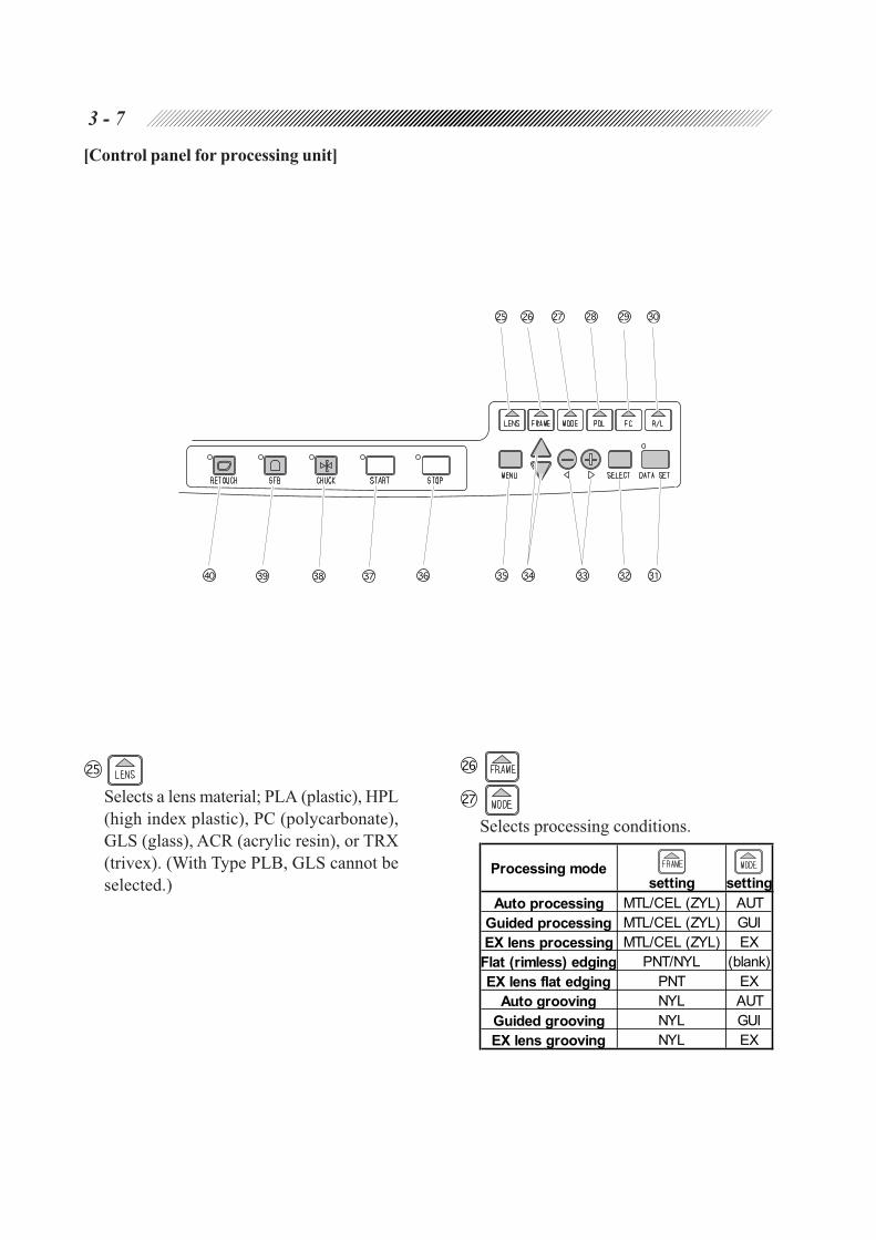
[Control panel for processing unit]
Selects a lens material; PLA (plastic), HPL
(high index plastic), PC (polycarbonate),
GLS (glass), ACR (acrylic resin), or TRX
(trivex). (With Type PLB, GLS cannot be
selected.)
Selects processing conditions.
Processing modesetting setting
Auto processing MTL/CEL (ZYL) AUT
Guided processing MTL/CEL (ZYL) GUI
EX lens processing MTL/CEL (ZYL) EX
Flat (rimless) edging PNT/NYL (blank)
EX lens flat edging PNT EX
Auto grooving NYL AUT
Guided grooving NYL GUI
EX lens grooving NYL EX
3 - 8
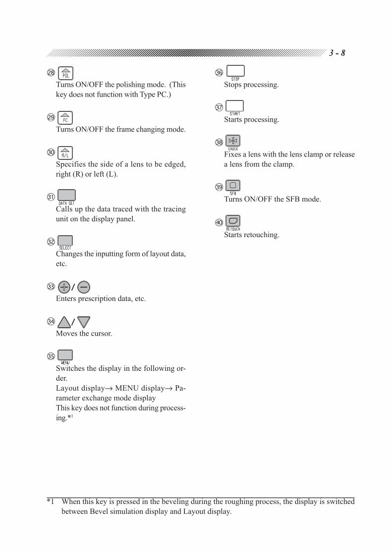
Turns ON/OFF the polishing mode. (This
key does not function with Type PC.)
Turns ON/OFF the frame changing mode.
Specifies the side of a lens to be edged,
right (R) or left (L).
Calls up the data traced with the tracing
unit on the display panel.
Changes the inputting form of layout data,
etc.
/////
Enters prescription data, etc.
/////
Moves the cursor.
Switches the display in the following or-
der.
Layout display→ MENU display→ Pa-
rameter exchange mode display
This key does not function during process-
ing.*1
*1 When this key is pressed in the beveling during the roughing process, the display is switched
between Bevel simulation display and Layout display.
Stops processing.
Starts processing.
Fixes a lens with the lens clamp or release
a lens from the clamp.
Turns ON/OFF the SFB mode.
Starts retouching.

3 - 9
[Display Panel]
• LAYOUT DISPLAY
Lens layout and prescription data input, etc. are performed on this display.
Frame pupillary distance
Pupillary distance
Height of optical center
Size compensation value
Layout mode
Memory address
Lens material Frame material
Processing mode
R/L indication
Traced outline
Minimum lens
diameter
Rim center
Optical center
Up direction
Frame pupillary distance (FPD)
Input the distance between right and left
rim centers. [30.00 - 99.50 mm (increment:
0.50 mm)] The rim centers are calculated
by the boxing system.
It is possible to input DBL by aligning the
cursor to FPD and pressing .
Pupillary distance (PD)
Input the pupillary distance referred in the
prescription. [30.00 - 99.50 mm (incre-
ment: 0.50 mm)] It is also possible to in-
put monocular PD (1/2PD).
Polishing indication
Frame changing indication
SFB indication
Height of optical center ( )
Input the height from the rim center (box-
ing center) to the optical center.
[↓15.0 - ↑15.0 mm (increment: 0.1 mm)]
DBL
FPD
3 - 10
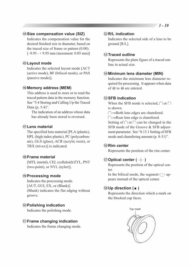
Size compensation value (SIZ)
Indicates the compensation value for the
desired finished size in diameter, based on
the traced size of frame or pattern (0.00).
[–9.95 - + 9.95 mm (increment: 0.05 mm)]
Layout mode
Indicates the selected layout mode [ACT
(active mode), BF (bifocal mode), or PAS
(passive mode)].
Memory address (MEM)
This address is used to store or to read the
traced pattern data in the memory function.
See “5.4 Storing and Calling Up the Traced
Data (p. 5-8)”.
The indication of an address whose data
has already been stored is reversed.
Lens material
The specified lens material [PLA (plastic),
HPL (high index plastic), PC (polycarbon-
ate), GLS (glass), ACR (acrylic resin), or
TRX (trivex)] is indicated.
Frame material
[MTL (metal), CEL (celluloid)/ZYL, PNT
(two-point), or NYL (nylor)].
Processing mode
Indicates the processing mode.
[AUT, GUI, EX, or (Blank)]
(Blank) indicates the flat edging without
groove.
Polishing indication
Indicates the polishing mode.
Frame changing indication
Indicates the frame changing mode.
R/L indication
Indicates the selected side of a lens to be
ground [R/L].
Traced outline
Represents the plain figure of a traced out-
line in actual size.
Minimum lens diameter (MIN)
Indicates the minimum lens diameter re-
quired for processing. It appears when data
of to are entered.
SFB indication
When the SFB mode is selected, or
is shown.
⇒Both lens edges are chamfered.
⇒Rear lens edge is chamfered.
Setting of or can be changed in the
SFB mode of the Groove & SFB adjust-
ment parameter. See “8.13.1 Setting of SFB
mode and chamfering amount (p. 8-31)”.
Rim center
Represents the position of the rim center.
Optical center ( )
Represents the position of the optical cen-
ter.
In the bifocal mode, the segment ap-
pears instead of the optical center.
Up direction ( )
Represents the direction which a mark on
the blocked cup faces.
Top mark

3 - 11
• Bevel simulation display
This display is shown while a bevel is
simulated (when the tilting function is
OFF).
This display is shown while a bevel is
simulated (with the tilting function).
• Groove simulation display
This display is shown while a groove is
simulated.
Groove sectional view
Groove curve
Groove dip point
Groove depth
Groove width
Sectional view position lineEdge thickest point
Edge thinnest point
Edge thickest point
Edge thinnest point
Sectional view position line
Bevel sectional view
Bevel curve
Bevel tip point
Frame curve
Bevel tilting amount
Tilt base position

3 - 12
Frame curve (F CRV)
Indicates the frame curve value measured
by the tracing unit.
Bevel tip point (PNT)
Indicates the amount by which the bevel
is moved, either backward or forward.
In the guided processing mode, align the
cursor toPPNT.. Change the value with
or to move the bevel forward
or backward parallel to itself.
[←15.0 - →15.0 mm (increment: 0.1
mm)]
Bevel curve (B CRV)
Indicates the bevel curve value.
In the guided processing mode, align the
cursor to B CRV and change the value
with or . The “A” mark on the
head of the value means that it is calcu-
lated by computer and is the optimum
value.
Bevel sectional view
Represents the bevel section where Sec-
tional view position line is on the traced
outline.
The mark “ ” over the scale represents
the bevel tip point.
One graduation of the scale is equal to
0.2 mm.
Sectional view position line
Represents the position of the indicated
bevel section along the traced outline.
Bevel tilting amount (TILT)
Indicates the amount by which the bevel
tip point is shifted forward or backward.
Adjust the bevel tip point at the diago-
nally-opposite to the boxing center the
tilt base position.
The value can be changed in 0.1 mm
increments.
Tilt base position
This is the base bevel position for deter-
mining a tilting amount.
Groove width (WID)
Indicates the groove width for nylor
frames.
[0.6 - 1.2 mm (increment: 0.1 mm)]
Groove depth (DEP)
Indicates the groove depth for nylor
frames.
[0.0 - 0.8 mm (increment: 0.1 mm)]
Groove dip point (PNT)
Indicates the amount that the groove for
nylor frames is moved, either backward or
forward.
In the guided grooving mode, align the
cursor toBPNT. Change the value with
or to move the groove forward
or backward parallel to itself.
[←15.0 - → 15.0 mm (increment: 0.1
mm)]
Groove curve (G CRV)
Indicates the groove curve value for nylor
frames.
In the guided grooving mode, align the
cursor to G CRV and change the value
with or . The “A” mark on the
head of the value means that it is calcu-
lated by computer and is the optimum
value.
Groove sectional view
Represents the groove section where
Sectional view position line is on the traced
outline.
The mark “ ” over the scale represents
the groove dip point.
One graduation of the scale is equal to
0.2 mm.

3 - 13
• MENU display
This display serves the selections such as
Process counter, Wheel dressing, Size ad-
justment, and Bevel adjustment. This is
used to perform maintenance or adjust-
ment of the edger.
• Parameter exchange mode display
This is a display to set parameters. On this
display, the initial settings of size, pupil-
lary distance (PD), height of the optical
center, and the parameter setting related
to data communication are done.
• Barcode display
This display is available only when the
edger is connected to the optional barcode
scanner. On this display, traced outline and
layout data of a lens are stored and called
up. This display appears when a barcode
is read with the barcode scanner.
• Error code display
When any abnormal condition is encoun-
tered, the system automatically stops and
the error code appears on the screen. See
“B. ERROR CODE”.

4.1 Operation Flow
Power-on
4.3 Tracings
4.3.1 Tracing frames (p. 4-4)
4.3.1.1 Tracing both rims (p. 4-4)
4.3.1.2 Tracing single rims (p. 4-5)
4.3.1.3 Semiauto tracing (p. 4-5)
4.3.1.4 Tracing goggle type frames (p. 4-6)
4.3.2 Tracing patterns (p. 4-7)
4.3.3 Tracing dummy lenses (p. 4-8)
4.3.4 Tracing during processing (p. 4-10)
4.3.5 Stopping tracing (p. 4-10)
4.3.5.1 Stopping frame tracing (p. 4-10)
4.3.5.2 Stopping pattern or dummy lens tracing (p. 4-10)
5.4 Storing and Calling Up the Traced Data
5.4.1 When the edger is not connected to the barcode scanner
(p. 5-9)
5.4.2 When the edger is connected to the barcode scanner (p. 5-10)
4.4 Layouts
4.4.1 Selecting processing conditions and inputting layout data (p. 4-11)
4.4.2 Inputting height from lens outline (p. 4-14)
4.4.2.1 Layout of bifocal lens (p. 4-15)
4.4.2.2 Layout of progressive power lens (p. 4-16)
4.4.3 Eye point layout (p. 4-17)
5.4 Storing and Calling Up the Traced Data
5.4.1 When the edger is not connected to the barcode scanner
(p. 5-9)
5.4.2 When the edger is connected to the barcode scanner
(p. 5-10)
4.5 Blocking Lenses
4.5.1 Blocking in active mode (p. 4-18)
4.5.1.1 Blocking progressive power lenses (p. 4-18)
4.5.2 Blocking in passive mode (p. 4-19)
4.5.3 Blocking bifocal lenses (p. 4-20)
§4OPERATING PROCEDURES
4 - 2
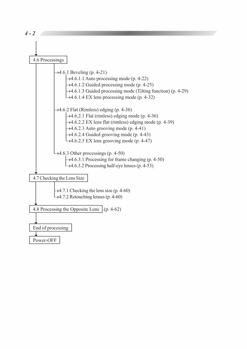
4.6 Processings
4.6.1 Beveling (p. 4-21)
4.6.1.1 Auto processing mode (p. 4-22)
4.6.1.2 Guided processing mode (p. 4-25)
4.6.1.3 Guided processing mode (Tilting function) (p. 4-29)
4.6.1.4 EX lens processing mode (p. 4-32)
4.6.2 Flat (Rimless) edging (p. 4-36)
4.6.2.1 Flat (rimless) edging mode (p. 4-36)
4.6.2.2 EX lens flat (rimless) edging mode (p. 4-39)
4.6.2.3 Auto grooving mode (p. 4-41)
4.6.2.4 Guided grooving mode (p. 4-43)
4.6.2.5 EX lens grooving mode (p. 4-47)
4.6.3 Other processings (p. 4-50)
4.6.3.1 Processing for frame changing (p. 4-50)
4.6.3.2 Processing half-eye lenses (p. 4-53)
4.7 Checking the Lens Size
4.7.1 Checking the lens size (p. 4-60)
4.7.2 Retouching lenses (p. 4-60)
4.8 Processing the Opposite Lens (p. 4-62)
End of processing
Power-OFF

4 - 3
4.2 Preparation
1. Plug the power cord in the wall outlet.
CAUTION
• Do not put many loads on one electrical outlet.
It may cause a fire.
• Pins of the plug must be fully inserted into the socket.
Incomplete connection may cause fire.
2. Turn the power ON.

4 - 4
Rim clips
4.3 Tracings
4.3.1 Tracing frames
NOTE
• Perform dummy lens tracing for rims which possess low stiffness such as thin-rim frames.
If the rim has low stiffness, distortion may occur and correct measurment cannot be
obtained.
4.3.1.1 Tracing both rims
This is a procedure to measure the outline of both rims as well as the FPD (Frame Pupillary Distance).
1. Set frames into the tracing unit.
1) Open the cover of the tracing unit.
2) Set the top of the frames.
Draw the lower slider and set the frame top
between the rim clips on the upper slider.
3) Set the bottom of the frames.
Slowly release the lower slider, placing the
frame bottom between the rim clips on the
lower slider.
4) Bring the frames to the center of the tracing
unit.
2. Start tracing both rims.
Press .
Tracing is complete when the frames are released.
3. Call up the traced data on the display.
Press .
The traced outline appears on the display.
4. Draw the lower slider to remove the frames.

4 - 5
NOTE
• If there is 1 mm or more of difference in circumference between right and left rims, the
tracing error occurs (Retracing starts automatically and the lamps beside and
blink for a few seconds) and pressing does not read the traced data. In such
a case, perform the single rim tracing.
4.3.1.2 Tracing single rims
This is a procedure to trace one of the frame rims.
1. Set frames into the tracing unit.
See Step 1 of “4.3.1.1 Tracing both rims” (p. 4-4).
2. Press either or .
For tracing the rim for left eye Press .
For tracing the rim for right eye Press .
NOTE
• FPD (Frame Pupillary Distance) cannot be measured when a single rim is traced.
Measure it manually and input the data on the Layout display.
4.3.1.3 Semiauto tracing
This is a procedure to bring the stylus into the bevel groove of the frame with fingers when the
stylus cannot be set in the groove automatically.
1. Set frames into the tracing unit.
See Step 1 of “4.3.1.1 Tracing both rims” (p. 4-4).
2. Hold *1 down for 3 seconds.
The stylus will move and stop at the tracing start position.
3. Use fingers to set the stylus into the groove.
*1 To trace a single rim, hold or down for three seconds.

4 - 6
4. Start tracing.
Press .
When tracing is complete for one rim, the stylus will move to the other rim and stop at the
tracing start position.
5. Trace the other rim in the same manner as Steps 3 - 4.
4.3.1.4 Tracing goggle type frames
When sharply warped frames such as goggles are traced, the stylus may come off the bevel
groove. In such a case, set only one rim between the rim clips and hold the frame temple of the
other side during tracing.
The following only describes the procedure for the right rim since either rim can be traced in the
same way.
1. Set a rim for the right eye horizontally to the tracing unit.
• Do not set the left rim.
• Hold the left temple of the frame to keep
the right rim horizontal.
2. Start tracing.
Press .
NOTE
• Though the rim clips hold the right rim
securely, do not take your hand off the
temple.
If the frame moves during tracing,
precise measurement cannot be made.
3. Call up the traced data.
Press .
The traced outline will appear on the display
panel.
4. Remove the frames from the tracing unit.
NOTE
• FPD (Frame Pupillary Distance) cannot be measured when goggle type frames are traced.
Measure it manually and input the data on the Layout display.
<Non-tracing side>
Hold with fingers.
Do not set between the
rim clips.
<Tracing side>
Set the rim horizontally be-
tween the rim clips.

4 - 7
4.3.2 Tracing patterns
1. Set a pattern onto the pattern setting unit.
1) Set a pattern while pressing the white button
on the pattern setting unit.
Make sure that the pattern is pushed as far
as it will go.
Fit the pattern as the following figure shows.
2) Release the white button to lock the pattern.
2. Set the pattern setting unit to the tracing unit.
1) Open the cover of the tracing unit.
2) Set the pattern setting unit to the tracing unit.
Draw the lower slider and set the pattern
setting unit onto the pattern setting unit
support.
Fit the pins of the pattern setting unit to the
two circular holes on the pattern setting unit
support.
The pattern setting unit is fixed to the pattern
setting unit support by magnet.
Nasal side Nasal sideTemporal side Temporal side
<For left pattern> <For right pattern>
Pattern setting unit support
Circular holesPins
White button
Pattern
Pattern setting unit

4 - 8
3. Press either or .
For tracing the right pattern Press .
For tracing the left pattern Press .
The tracing pin comes out and then tracing
starts.
4. When tracing is completed, remove the
pattern setting unit.
When tracing is complete, the tracing pin will
be automatically stored.
It is easy to remove the unit from the left side.
NOTE
• FPD (Frame Pupillary Distance) cannot be measured when a pattern is traced.
Measure it manually and input the data on the Layout display.
4.3.3 Tracing dummy lenses
1. Block the convex side of a dummy lens with a lens cup.
1) Mark the estimated center of a dummy lens
with a lensmeter.
Set the dummy lenses mounted in the frames
and make sure that the frames are in contact
with the lens table to mark the lenses.
2) Affix the provided double-coated adhesive
tape on a lens cup.
Lens table

4 - 9
3) Block the convex side of the dummy lens with
the lens cup, using a centering device.
Align the marks on the dummy lens to the
direction of the groove on the lens cup to
block it.
2. Set the lens cup onto the pattern setting unit.
Fit the lens cup while pressing the white button
of the pattern setting unit.
3. Trace the dummy lens in the same manner as Steps 2 - 4 of “4.3.2 Tracing pattern” (p. 4-
7).
However, press to trace the right-eye lens, and press to trace the left-eye lens.
NOTE
• FPD (Frame Pupillary Distance) cannot be measured when a dummy lens is traced.
Measure it manually and input the data on the Layout display.
Instead of inputting FPD, you may also use the eye point layout. See “4.4.3 Eye
point layout” (p. 4-17).
Lens cup
Nasal sideNasal side Temporal sideTemporal side
<For left-eye lens>
White button
Pattern setting unit
<Convex side of dummy lens>
<For right-eye lens>
4 - 10
4.3.4 Tracing during processing
It is possible to perform the next tracing during processing.
Set frames and press .
After the processing is complete, press . The data of the traced outline will be set and
shown on the display.
4.3.5 Stopping tracing
To stop tracing, follow the instructions below.
4.3.5.1 Stopping frame tracing
1. Press .
The stylus will return to its original position and the frames will be released.
4.3.5.2 Stopping pattern or dummy lens tracing
1. Press .
2. Remove the pattern setting unit.
The tracing pin will be stored.

4 - 11
1) 2) 3) 4)
Processing
typeProcessing mode
setting setting
Auto processing MTL/CEL (ZYL) AUT
Guided processing MTL/CEL (ZYL) GUI
EX lens processing MTL/CEL (ZYL) EX
Flat (rimless) edging PNT/NYL (blank)
EX lens flat edging PNT EX
Auto grooving NYL AUT
Guided grooving NYL GUI
EX lens grooving NYL EX
Beveling
Flat edging
Processing mode EX
Type of lens CRV FRNT REAR RATIO
Progressive power
Bifocal
Cataract
EX
AUTGUI
Special lenses
Monofocal lens
4.4 Layouts
4.4.1 Selecting processing conditions and inputting layout data
1. Select processing conditions.
1) Specify the material of a lens with .
[PLA (plastic), HPL*2 (high index plastic),
PC (polycarbonate), GLS*3 (glass), ACR
(acrylic resin), or TRX (trivex)*4
CAUTION
• Be sure to specify a correct lens material.
Otherwise, the useful life of processing wheel may be shortened.
2) Select the beveling or flat (rimless) edging with .
[MTL, CEL (ZYL), PNT, NYL]
Flat (rimless) edging Select [PNT] or [NYL] suited to the frame form.
Beveling Select [MTL] or [CEL] suited to the lens material.
3) Select a processing mode.
The processing mode can be selected with
or .
See the table on the right.
For adjusting a bevel or groove position
Select the GUI mode.
For processing an EX lens
Select the EX mode.
For processing a cataract lens
Select the GUI mode (rear surface).
For beveling, select the optimum mode suited to the lens material.
: Optimum mode, : Recommended mode
*2 Select HPL when processing plastic lenses which produce burrs and chips easily.
*3 Glass lenses cannot be processed with Type PLB.
*4 To process lenses that melt easily from heat such as a trivex lens, select “TRX”.

4 - 12
NOTE
• EX lenses cannot be processed in auto processing mode and guided processing mode.
Process an EX lens after checking the bevel position or groove position in EX lens processing
mode.
• Cataract lenses cannot be processed in auto processing mode.
Process a cataract lens with the curve profiling the rear surface while checking the
bevel position or groove position in guided processing mode.
If a cataract lens has a large dilation on its front convex surface, the lens measurement
error may occur. In such a case, process the lens in EX lens processing mode.
4) Specify the side of a lens to be processed, either R (right) or L (left) with .
5) Press to turn ON the polishing mode. (Only for PL4, PLB and PLB-2R. For Type PL4, this
function is available only when the flat edging is selected.)
Press again to cancel the polishing mode.
6) Press to turn ON the SFB mode.
The lamp beside lights up, and or is shown on the display panel.
2. As necessary, change the setting of the layout mode.
Align the cursor (C ) to the layout mode indication and select the desired mode with . See
[ACT (Active mode), BF (Bifocal mode), PAS (Passive mode)] of “A.3 Selection of Blocking”
(p. A-4).
3. Input each data of the lens layout.
Input values of FPD*5, PD and height of the
optical center.
1) Input the PD value on the prescription.
Align the cursor (C ) to PDC with
or , and input a PD value with or
.*6
*5 It is possible to input DBL.
It is a method of inputting the distance between nasal ends of right and left rims.
1) Align the cursor to FPD and press .
FPD changes to DBL.
2) Input a DBL value with or .
PD
FPD
Height of optical
center ( )DBL

4 - 13
2) Input the height of the optical center.
Align the cursor to and input a height
of the optical center from the level of the
frame center with or .*7
3) To correct the finished lens size, align the cursor to SIZ and input the corrective value with
or .
e.g. +1.00: The finished size becomes 1 mm larger in diameter.
The minimum lens diameter required for processing is shown on the top right of the display
at MIN.
NOTE
• This value is provided just for a reference purpose. It is recommended to use a lens
which is 2 - 3 mm longer in diameter in a case that the optical center and the center of
the lens are not the same.
[When the mark of the optical center becomes ]
When the layout is input, the mark of the optical
center may change from to .
indicates that the lens adapter or lens clamp
may contact with the wheels during processing.
Replace the lens adapter, lens clamp and lens
cup with the ones for half-eye lens.
See “4.6.3.2 Processing half-eye lenses” (p. 4-
53).
*6 It is also possible to input PD by monocular PD. It is a method of inputting the bridge center to
the eye point distance for the right and left lenses separately.
1) Align the cursor to PDC and press .
PDC changes to 1/2PD.
2) Input a monocular PD value with or
.
*7 It is also possible to input a height of the optical center by the eye height from the bottom of the
lens outline. See “4.4.2 Inputting height from lens outline” (p. 4-14).
1)
2)
3)

4 - 14
4.4.2 Inputting height from lens outline
1. Select an inputting form.
Align the cursor to and select either of
the followings with .
PD : Height of the optical center from the
straight-down point on the lens out-
line.
BT : Height of the level of optical center
from the lowest point of the outline.
2. Input a height of the optical center.
e.g. If the height of the optical center
from the straight-down point on the
outline is 23.5 mm;PD : 23.5
e.g. If the height at the level of the opti-
cal center from the lowest point of
the outline is 25.8 mm;BT : 25.8
PD
BT

4 - 15
4.4.2.1 Layout of bifocal lens
1. Select processing conditions.
See “4.4.1 Selecting processing conditions and inputting layout data” (p. 4-11).
2. Select BFC (bifocal) for the layout mode.
3. Input the prescribed PD for the near vision
(PD of segment) at PDC.
4. Align the cursor to and select
or with .
5. Input the segment at the center of top line.
PD : Height of the center point of the seg-
ment top line to the straight-down
point on the lens outline
BT : Height of the center level of the seg-
ment top line to the lowest point on
the lens outline
For the blocking procedure, see “4.5.3 Blocking bifocal lenses” (p. 4-20).
BTPD

4 - 16
4.4.2.2 Layout of progressive power lens
1. Select processing conditions.
See “4.4.1 Selecting processing conditions and inputting layout data” (p. 4-11).
2. Select ACT (Active) for the layout mode.
3. Input the prescribed PD at PD .
4. Input the height of the eye point marked on
a dummy lens.
See “4.4.2 Inputting height from lens outline”
(p. 4-14).
For the blocking procedure, see “4.5.1.1
Blocking progressive power lenses” (p. 4-18).

4 - 17
4.4.3 Eye point layout
This is a form to input the optical center by the
distance from the nasal and bottom side of the
lens outline.
This form serves to specify the position of the
eye point, which is marked on dummy lenses,
as the optical center.
1. Align the cursor to FPD and press
twice.
The display changes as shown in the right
figure.
The mark “ ” in the traced outline shows
the position of the eye point.
The display with FPD will return if is
pressed again.
2. Input the distance from the eye point to its
nasal level point on the lens outline at .
3. Input the height of the eye point from its
straight-down point on the lens outline at
.
PD

4 - 18
4.5 Blocking Lenses
A blocking position of the suction cup varies with the layout mode (Active mode, Bifocal mode, Passive
mode).
4.5.1 Blocking in active mode
1. Mark at the optical center of a lens with a
lensmeter.
When a lens has cylinder power, align the
cylinder axis angle of the lens to the prescription
value before marking.
It is recommended to use NIDEK Auto
lensmeter for this purpose.
2. Block the convex surface of the lens with a
suction cup.
The cup has blocking direction as shown with
the top mark.
Be careful not to block the wrong side up,
especially for dual-tone colored lens.
It is recommended to use NIDEK centering
device Model CE-1 for blocking.
NOTE
• For processing a polycarbonate lens, be sure to use a lens cup in order to prevent the
cup from moving during processing.
4.5.1.1 Blocking progressive power lenses
Block a lens with a centering device on the eye
point for far vision, which is printed on the lens.
Cylinder axis
<Up side>
Eye point for far vision

4 - 19
4.5.2 Blocking in passive mode
This is a procedure to block at the rim center by
decentering the optical center.
When PAS (Passive) is selected for the layout
mode, how much and in what direction the
optical center should be decentered appears at
PAS after the lens layout is finished.
The on-the-frame-center blocking can be
achieved by decentering the optical center as
indicated.
1. Mark at the optical center of a lens with a
lensmeter.
See Step 1 of “4.5.1 Blocking in active mode”
(p. 4-18).
2. Block the convex surface of the lens with a
suction cup.
Decenter the optical center in accordance with
the indication at PAS .
e.g. PAS : 2.0
: 5.0
Decenter the optical center 2.0 mm to the right
and 5.0 mm to the bottom to block.
NOTE
• For processing a polycarbonate lens, be sure to use a lens cup in order to prevent the
cup from moving during processing.
2 mm
5 mm
Marked point
<When using NIDEK centering device CE-1>

4 - 20
5 mm
5 mm
<When using NIDEK centering device CE-1>
5 mm up
5 mm outside
4.5.3 Blocking bifocal lenses
When BF (bifocal) is selected for the layout mode, a lens is blocked at the specified value UP and OUT
position from the top line center of segment.
Be sure to block the lens as instructed below since the edger processes the lens with the specified
values. See “4.4.2.1 Layout of bifocal lens” (p. 4-15).
Block a lens at 5 mm up and 5 mm outside
position from the top line center of the
segment with a lens cup (When using the
NIDEK centering device CE-1).
NOTE
• The edger is factory-configured so that a lens is blocked at 5 mm up and 5 mm outside
position with the NIDEK centering device CE-1. (The provided layout mark of segment
on the screen of the CE-1 allows an operator to easily block a lens at 5 mm up and 5
mm outside.) When using the centering device of the other manufacturer, it is possible
to specify appropriate values to the device. See “5.2 Parameter Settings” (p. 5-2).

4 - 21
4.6 Processings
Processing mode is specified by and .
See Step 1. of “4.4.1 Selecting processing conditions and inputting layout data” (p. 4-11).
To turn ON the SFB mode, press .
The edge will be polished by pressing on Type PL4, PLB, or PLB-2R. (This function is available
only for flat edging of Type PL4.)
4.6.1 Beveling
For beveling, select the optimum mode suited to the lens material.
: Optimum mode, : Recommended mode
NOTE
• EX lenses cannot be processed in the auto processing mode and guided processing mode.
Process an EX lens in EX lens processing mode. See “4.6.1.4 EX lens processing mode”
(p. 4-32).
• Cataract lenses cannot be processed in auto processing mode.
Process a cataract lens with the curve profiling the rear surface in guided processing mode.
See “4.6.1.2 Guided processing mode” (p. 4-25).
If a cataract lens has a large dilation on its front convex surface, the lens measurement
error may occur. In such a case, process the lens in EX lens processing mode.
*8 Specify the ratio, following the reference ratios below.
• Low power plus monofocal lens 5 : 5
• Middle and high power plus monofocal lens, Low power minus monofocal lens 4 : 6 or 5 : 5
• Medium power minus monofocal lens 3 : 7 or 4 : 6
• High power minus monofocal lens 3 : 7
*8
setting setting
Auto processing mode (see p. 4-22) MTL/CEL (ZYL) AUT
Guided processing mode (see p. 4-25) MTL/CEL (ZYL) GUI
EX lens processing mode (see p. 4-32) MTL/CEL (ZYL) EX
Flat (rimless) edging mode (see p. 4-36) PNT/NYL (blank)
EX lens flat (rimless) edging mode (see p. 4-39) PNT EX
Auto grooving mode (see p. 4-41) NYL AUT
Guided grooving mode (see p. 4-43) NYL GUI
EX lens grooving mode (see p. 4-47) NYL EX
Processing mode
Flat edging
Beveling
Processing mode
Type of lens CRV FRNT REAR RATIO
Progressive power
Bifocal
Cataract
EX
EXAUTGUI
Special lenses
Monofocal lens

4 - 22
4.6.1.1 Auto processing mode
In this mode, a computer-calculated bevel is produced on the lens edge.
1. Check the processing conditions.
: MTL or CEL (ZYL)
: AUT
2. Set a lens to the adapter in the processing
unit.
Align the top mark (•) on the suction cup with
that of the adapter and insert the suction cup
firmly. Then, press to fix the lens.
NOTE
• To attach a suction cup or lens cup to the adapter, align the top mark of the cup with the
mark on the adapter and fully insert the cup.
If not, correct processing cannot be done. As for the lens cup, if it the attached lens
cup to the adapter is upside down, the lens cup cannot be held securely by the adapter.
[Positions of the top mark]
CAUTION
• Be careful not to get your fingers caught when chucking (fixing) a lens.
Top mark
Top mark
Suction cup
Lens cup
Lens cup for half-eye lens
Standard adapter
Adapter for half-eye lens
Top mark
Top mark
Top mark
Top mark
Top mark

4 - 23
3. Close the soundproof cover.
Processing does not start even if is pressed unless the soundproof cover is closed.
WARNING
• Be sure to keep the soundproof cover closed while processing a lens.
If the soundproof cover is opened during processing, the instrument does not stop.
Spray including processing waste may cause eye damage.
4. Start processing.
Press .
Lens shape measurement
Roughing
[The display changes to the Bevel simulation
display.]
Finishing
Polishing (Only when is selected by Type PLB or PLB-2R.)
Chamfering (Only when is selected.)
Processings are complete. [The Layout display returns.]
When the display changes to the Bevel simulation display in Step , sectional view position line
rotates along the traced outline, and bevel section at that position will be shown.
A. The glass lens contact position can be moved laterally during roughing. (Type PL4 and
PLB-2R)
By changing the position where the glass lens contacts the roughing wheel, the partial wear of
the roughing wheel for glass lens will be unlikely to occur.
To adjust the contact position, press or
during the roughing.
: The contact position with the wheel will
shift to the right.
: The contact position with the wheel will
shift to the left.
Sectional view position line
Bevel section
Roughing wheel for glass lens

4 - 24
Roughing wheel for plastic lens
NOTE
• Be sure to move a glass lens within the roughing wheel for glass lenses.
If the glass lens contacts the other wheels, it may damage the wheels or the glass lens
may crack.
• The adjusted contact position with the wheel is effective only during the roughing of
one lens. After the lens processing is over, the contact position with the wheel will
return to its original position.
• Setting the “Reverse GLS Grind” parameter to “Exec” roughly processes a lens by
automatically changing the position to be contacted with the roughing wheel from side to
side. In such a case, the position to be contacted cannot be changed with or .
B. It is possible to adjust the plastic lens contact position laterally during roughing.
If the sharply-warped or high minus plastic lens is detached from the roughing wheel, change
the position where the plastic lens contacts the roughing wheel.
To adjust the contact position, press or
during roughing.
: The contact position with the wheel will
shift to the right.
: The contact position with the wheel will
shift to the left.
NOTE
• The adjusted contact position with the wheel is effective only in the roughing of one
lens. After the lens processing is over, the contact position with the wheel will return to
its original position.
5. Take the finished lens off.
1) Open the soundproof cover.
2) Press to take the lens off.
WARNING
• Open the soundproof cover after making sure that the wheels have come to a complete stop.
• Release the chuck by pressing after making sure that the wheels have come to a complete
stop.
If the chuck is released before the wheels have not stopped completely and a lens is
dropped, it may contact the turning wheels and its scattering may cause injury.

4 - 25
4.6.1.2 Guided processing mode
This is a mode to input the value of bevel curve and bevel position manually.
1. Check the processing conditions.
: MTL or CEL (ZYL)
: GUI
2. Set a lens to the adapter in the processing
unit.
See Step 2 of “4.6.1.1 Auto processing mode”.
3. Close the soundproof cover.
Processing does not start even if is pressed unless the soundproof cover is closed.
WARNING
• Be sure to keep the soundproof cover closed while processing a lens.
If the soundproof cover is opened during processing, the instrument does not stop.
Spray including processing waste may cause eye damage.
4. Press .
Lens shape measurement
The display changes to the Bevel Simulation
display and the system stops.
5. Simulate the bevel section at each point of
the traced outline on the display.
: The sectional view position line rotates counterclockwise.
: The sectional view position line rotates clockwise.
To stop the line movement, press or again.
: The sectional view position line jumps to the point that the lens edge is thinnest ( ) and
thickest ( ) alternately.
Sectional view position line

4 - 26
6. Adjust the bevel position.
(a) Changing the bevel position only at the part that the edge is thick
1) Align the cursor to B CRV.
2) Change the bevel curve value to move the
bevel position toward the front or rear
surface of the lens.
: The bevel curve turns sharp.
: The bevel curve turns slight.
As the curve value is changed, the bevel
position moves from the edge thinnest point
as the base (The ratio 5:5 will be maintained).
The shifted amount of the bevel is the
maximum at the lens edge thickest point.
Change the bevel curve, watching the bevel
sectional view at the lens edge thickest point.
The curve value with the “A” mark on the head shows that it is a computer-calculated value.
This value produces the same bevel curve that is processed in the auto processing mode.
: The front base curve (FRNT), rear base curve (REAR), or ratio will be selected.
Specified curve value Front base curve Rear base curve Ratio
(curve profiling (curve profiling
the front surface the rear surface
of lens) of lens)
NOTE
• The curve value can only be selected within a range that the bevel is on the lens edge.
Therefore, the bevel will never be off the edge, and a single-sided bevel will never be
produced even though the bevel curve value is changed.
• When processing a cataract lens, select the rear base curve (REAR) for the curve
value.
The specified value, front base curve, or ratio is not appropriate for proper beveling.
The bevel curve
turns slight.
The bevel curve
turns sharp.
<Convex lens>
The bevel curve
turns slight.
The bevel curve
turns sharp.
<Concave lens>

4 - 27
(b) Changing the position of the whole bevel parallel to itself
1) Press to simulate the bevel at the point
that the edge is thinnest ( ).
2) Align the cursor to PNT.
3) Change the bevel tip point value to move
the bevel position toward the front or rear
surface of the lens.
: The bevel moves toward the front
surface.
: The bevel moves toward the rear
surface.
at the value shows that the bevel was
moved toward the front surface. at the
value shows that the bevel was moved
toward the rear surface.
e.g. B CRV: A5.0
PNT: 0.6
This shows that the bevel was moved 0.6 mm toward the rear surface parallel to itself while
the bevel curve value was 5.0.
NOTE
• In order to avoid the bevel being off the lens edge, be sure to watch the simulation at
the thinnest position while changing the value.
As distinct from changing the bevel curve value, it is possible to specify a bevel tip
point which produces a single-sided bevel.
7. Check the bevel section.
1) Press to turn off the cursor.
2) Simulate the whole bevel to see if the
desired bevel is obtained. See Step 5 (p. 4-
25).
8. Repeat Steps 5 - 7 until the desired bevel is obtained.
The bevel moves
toward the rear
surface.
The bevel moves
toward the front
surface.
4 - 28
9. Start processing.
Press .
Roughing
Finishing
Polishing (Only when is selected by Type PLB or PLB-2R.)
Chamfering (Only when is selected.)
Processings are complete. [The Layout display returns.]
10. Take the lens off.
WARNING
• Open the soundproof cover after making sure that the wheels have come to a complete stop.
• Release the chuck by pressing after making sure that the wheels have come to a complete
stop.
If the chuck is released before the wheels have not stopped completely and a lens is
dropped, it may contact the turning wheels and its scattering may cause injury.
• It is also possible to switch the processing mode to the guided processing mode even in the
middle of the auto processing.
To do so, press while the roughing is being processed.
After the roughing is completed, the instrument goes into the guided processing mode, and it
stops.
• While the Simulation display is shown, it can be changed to the Layout display by pressing
. The Layout display here, however, is just a reminder and its data cannot be changed.
(The switches except for do not function.)
Pressing again will return to the Simulation display, but once processing has started, the
display cannot be changed any more.

4 - 29
4.6.1.3 Guided processing mode (tilting function)
The tilting function of bevel is available in guided processing mode, in which the bevel curve can be
specified manually.
If the difference in width between the edge thickest point and thinnest point is extreme, the mounted lens
does not look nice. The appearance of the lens will get better if the bevel is tilted.
To use the tilting function, set the “TILT Function” parameter to “Exec”. See “5.2 Parameter Settings”
(p.5-2).
1. Select processing conditions, chuck a lens, and measure the lens shape.
After the lens shape measurement, the display changes to the simulation display, and the
instrument stops.
See Steps 1 - 5 of “4.6.1.2 Guided processing mode” (p. 4-25).
2. Adjust the bevel position.
1) Press or to move the sectional view
position line to the base position, and check
the bevel sectional view at that point.
The most appropriate tilt base position is the thinnest point of the lens edge, or a diagonally-
opposite point (through the frame center) to where the bevel apex point is to be moved.
2) Align the cursor to TILT with or ,
and press to determine the tilt base
position.
The tilt base position mark ( ) will move
to the end of the sectional view position line.
After that, the line will automatically skip
to the diagonally-opposite point.
If the value is already input at “TILT”,
pressing resets the value to 0.0.
In this case, press again to set the tilt
base position.

4 - 30
3) Align the cursor to B CRV with or , and set the bevel curve value with or .
Press or once to delete A (Auto-curve), and then set the desired value.
e.g.)A4.3: A bevel position is computer-calculated from the ratio.
4.3: A bevel position is calculated from the spheric curve of the lens.
With the curve value with A, a bevel position is calculated from Ratio. With the curve value
without A, the bevel position is calculated from the spherical curve of the lens.
With the tilting function, the bevel position is adjusted according to the spherical curve
value of the lens as a base. For the reason, if the ratio curve value with A is set, the set tilting
value may differ from the actual tilting amount of the bevel. As the difference between the
ratio curve and spherical curve is wide, the difference in the tilting amount will more
substantial will increase.
4) As necessary, align the cursor to PNT with or , and adjust the bevel position with
or .
The whole bevel moves toward the rear surface parallel to itself.
The whole bevel moves toward the front surface parallel to itself.
at the head of the value shows that the bevel is moved forward.
at the head of the value shows that the bevel is moved backward.
5) Align the cursor to TILT with or , and set the tilting amount with or .
“TILT” shows the amount of tilting the bevel tip point at the diagonally-opposite point to
the tilt base position.
The bevel moves toward the rear surface.
The bevel moves toward the front surface.
+ at the head of the value shows that the bevel is moved backward.
– at the head of the value shows that the bevel is moved forward.
6) Simulate the whole bevel to see if the desired bevel is obtained.
Delete the cursor with or , and check the bevel sectional view, by rotating the bevel
sectional view position line with or .
Pressing will move the sectional view position line to:
Tilt base position ( ) Diagonally-opposite point to the tilt base position
Edge thinnest point ( ) Edge thickest point ( ) in order
7) Repeat Steps 3) to 6) until the desired bevel is obtained.
Press to disable the set values for the bevel and to stop the instrument. All the set
values will be canceled, and the Layout display will return.

4 - 31
3. Restart processing.
Press to restart processing.
If the bevel is completely off the lens edge, the two short beeps will be produced. The sectional
view position line automatically rotates along the whole traced outline and bevel section at
each position will be shown.
Change the setting as necessary. To process the lens without changing the setting, press
again.
This function works when no apex of the bevel remains on the edge.
After roughing and finishing, processing sequences are over. The Layout display returns.
4. Take the lens off.
WARNING
• Open the soundproof cover after making sure that the wheels have come to a complete stop.
• Release the chuck by pressing after making sure that the wheels have come to a complete
stop.
If the chuck is released before the wheels have not stopped completely and a lens is
dropped, it may contact with the turning wheels and its scattering may cause injury.
5. When the other side is subsequently processed by switching R or L side, the former setting
for the lens side will be shown on the display.
If one side of the lens is processed with the tilting function, the Bevel simulation display will
automatically appear after the other side is processed by switching R or L. The former values
such as the tilt base position, amount of tilting bevel, bevel curve and bevel tip point are initially
displayed.
NOTE
• If the front base curve (FRNT), rear base curve (REAR) or Ratio is selected as the
bevel curve, the amount of tilting bevel will be ignored. The lens will be processed in
the normal guided processing mode.
• With the tilting function, the bevel curve will be calculated from the spherical curve of
the lens. For the reason, the bevel may be off the edge even though the closer value to
the auto-curve value is set.
• If the lens is processed with the bevel curve value with A on condition that the “Tilt Function”
parameter is set at “Exec”, the parameter setting will be ineffective, and the function of tilting
the bevel does not work.

4 - 32
4.6.1.4 EX lens processing mode
This mode serves to process EX lenses. In this mode, the beveling which has the curve profiling the rear
surface is performed.
As for a cataract lens which has a large dilation on its front convex surface, process a lens in the
EX lens processing mode if the lens processing cannot be performed in the guided processing
mode (rear base curve) due to the lens shape measurement error.
NOTE
• Use a lens cup for blocking.
A suction cup cannot hold the convex surface of a lens well enough. The cup may
move during blocking.
1. Check the processing conditions.
: MTL or CEL (ZYL)
: EX
2. Set a lens to the adapter in the processing unit.
See Step 2 of “4.6.1.1 Auto processing mode”.
3. Close the soundproof cover.
Processing does not start even if is pressed unless the soundproof cover is closed.
WARNING
• Be sure to keep the soundproof cover closed while processing a lens.
If the soundproof cover is opened during processing, the instrument does not stop.
Spray including processing waste may cause eye damage.
4. Press .
Lens shape measurement
The display changes to the Bevel simulation display and the instrument stops.
4 - 33
5. Simulate the bevel section at each point of the outline on the display.
: The sectional view position line rotates counterclockwise.
: The sectional view position line rotates clockwise.
To stop the line movement, press or again.
: The sectional view position line jumps to the point that the lens edge is thinnest ( ) and
thickest ( ) alternately.
If the bevel position needs to be changed:
Follow the procedures from Step 6 of “4.6.1.2 Guided processing mode” (p. 4-25) to change
the bevel tip point (PNT).
NOTE
• As to the curve value, do not change but leave it as the rear base curve (REAR).
The specified curve, front base curve, or ratio is not appropriate for proper beveling.
6. Start processing.
Press .
Roughing
Finishing
Polishing (Only when is selected by Type PLB or PLB-2R.)
Chamfering (Only when is selected.)
Processings are complete. [The Layout display returns.]
7. Take the lens off.
WARNING
• Open the soundproof cover after making sure that the wheels have come to a complete stop.
• Release the chuck by pressing after making sure that the wheels have come to a complete
stop.
If the chuck is released before the wheels have not stopped completely and a lens is
dropped, it may contact the turning wheels and its scattering may cause injury.
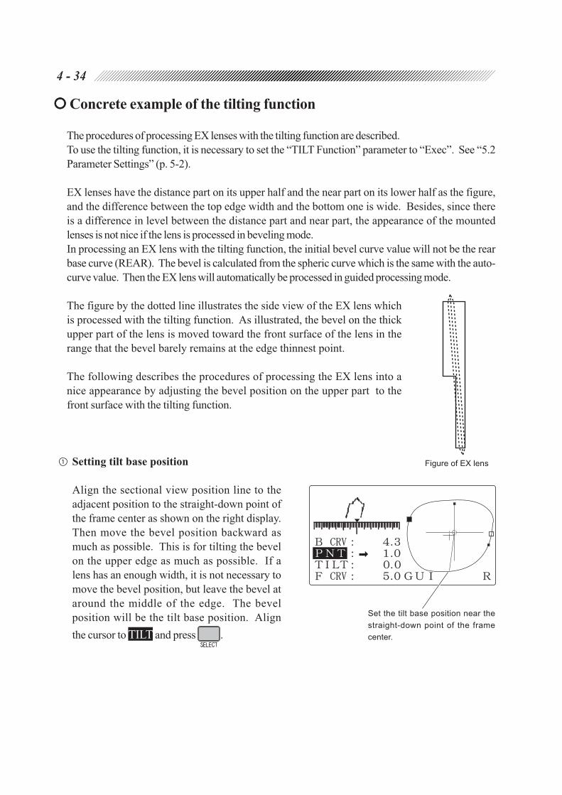
4 - 34
Concrete example of the tilting function
The procedures of processing EX lenses with the tilting function are described.
To use the tilting function, it is necessary to set the “TILT Function” parameter to “Exec”. See “5.2
Parameter Settings” (p. 5-2).
EX lenses have the distance part on its upper half and the near part on its lower half as the figure,
and the difference between the top edge width and the bottom one is wide. Besides, since there
is a difference in level between the distance part and near part, the appearance of the mounted
lenses is not nice if the lens is processed in beveling mode.
In processing an EX lens with the tilting function, the initial bevel curve value will not be the rear
base curve (REAR). The bevel is calculated from the spheric curve which is the same with the auto-
curve value. Then the EX lens will automatically be processed in guided processing mode.
The figure by the dotted line illustrates the side view of the EX lens which
is processed with the tilting function. As illustrated, the bevel on the thick
upper part of the lens is moved toward the front surface of the lens in the
range that the bevel barely remains at the edge thinnest point.
The following describes the procedures of processing the EX lens into a
nice appearance by adjusting the bevel position on the upper part to the
front surface with the tilting function.
Setting tilt base position
Align the sectional view position line to the
adjacent position to the straight-down point of
the frame center as shown on the right display.
Then move the bevel position backward as
much as possible. This is for tilting the bevel
on the upper edge as much as possible. If a
lens has an enough width, it is not necessary to
move the bevel position, but leave the bevel at
around the middle of the edge. The bevel
position will be the tilt base position. Align
the cursor to TILT and press .
Figure of EX lens
Set the tilt base position near the
straight-down point of the frame
center.

4 - 35
Inputting tilting amount
The bevel position has been moved backward in Step though the upper part of the edge is
thick. Move the bevel forward by inputting a minus value to “TILT”. In doing so, always
observe the bevel on the boundary between the distance and near parts. In most cases, the edge
thinnest point is on the boundary. Adjust the tilting amount within a range that at least a bevel on
either front or rear side remains.
See the following in adjusting the bevel position on each point. To reset all the settings, reset
“TILT” and “PNT” to 0.0, and put “A (automatically-calculated curve value)” at the head of the
curve value. This will allow an operator to reset the bevel position and tilting amount from the
beginning.
Adjacent point to the straight-down point
from the frame center (tilt base position)
• If the lens edge is thin, change the bevel tip
point (PNT) to move the bevel backward as
much as possible.
• If the lens has enough width, place the bevel
tip point at 1/3 from the rear surface of the
edge.
• Do not input the tilting amount, and leave
“TILT” 0.0.
Upper position (diagonally-opposite point to
the tilt base point)
• Move the bevel position forward as much
as possible in the range that the bevel on the
edge thinnest point remains on the edge.
• Increase the tilting amount (TILT) to the
minus direction to tilt the bevel toward the
front surface.
Edge thinnest point (on the boundary
between the distance part and near part)
• Move the bevel position on the upper part
forward, observing that the bevel tip point
at the edge thinnest point remains on the
edge.
• Set such a tilting amount (TILT) that the tip
of the bevel barely remains.
Boundary between the distance part
and near part

4 - 36
4.6.2 Flat (rimless) edging
In addition to the normal flat edging, grooving for nylor frames can be performed after the flat edging.
The EX lens flat edging mode is also available for EX lenses in the normal flat edging.
In this mode, the auto grooving mode in which groove position and curve are calculated from
measured data of a lens, the guided grooving mode in which data is manually input, and the EX
lens grooving mode for grooving a EX lens are available.
4.6.2.1 Flat (rimless) edging mode
1. Check the processing conditions.
: PNT*9 or NYL
: (Blank)
2. Set a lens to the adapter in the processing unit.
See Step 2 of “4.6.1.1 Auto processing mode”.
3. Close the soundproof cover.
Processing does not start even if is pressed unless the soundproof cover is closed.
WARNING
• Be sure to keep the soundproof cover closed while processing a lens.
If the soundproof cover is opened during processing, the instrument does not stop.
Spray including processing waste may cause eye damage.
4. Start processing.
Press .
Lens shape measurement*10
Roughing
*9 When PNT (Two-point) is selected, FPD will be automatically corrected.
Auto-correction of FPD is the function which changes the FPD value in accordance with the
changed size value.
*10 The “ Lens shape measurement” will not be performed if the “Measure in flat edge” parameter is set
to “None”. See “5.2 Parameter Settings” (p. 5-2). However, the lens shape measurement will be
performed regardless of the setting if grooving and chamfering are performed.

4 - 37
Finishing
Polishing (Only when is selected by Type PL4, PLB, or PLB-2R.)
Chamfering (Only when is selected.)
Processings are complete. [The Layout display returns.]
* The processing order may change according to the lens material.
5. Take the lens off.
WARNING
• Open the soundproof cover after making sure that the wheels have come to a complete stop.
• Release the chuck by pressing after making sure that the wheels have come to a complete
stop.
If the chuck is released before the wheels have not stopped completely and a lens is
dropped, it may contact the turning wheels and its scattering may cause injury.
NOTE
• When the lens, which is hard to be processed or whose edge is thick, is polished, a part
of the edge may remain unpolished.
In such a case, retouch the lens without changing size compensation value. See
“4.7.2 Retouching lenses” (p. 4-60).

4 - 38
[Addition of grooving]
When the “To add safety bevel” parameter is set to “Exec”, grooving can be additionally performed
(except for glass lenses) after the flat edging with the frame setting of “NYL”.
However, as well as retouching, this cannot be performed such as when removing the suction
cup, switching R/L, or reading other frame data.
1) Select “AUT” or “GUI” with .
2) Set a lens to the adapter in the processing
unit.
Align the top mark (•) on the suction cup
with that of the adapter and insert the suction
cup firmly.
3) Press or .
Grooving is performed.
After retouching, grooving is performed.
If “GUI” has been selected in Step 1), the instrument will change to the Simulation display and stop
temporarily. Check the groove section and adjust the depth and width, etc. as necessary. Then,
press to start grooving. See “4.6.2.4 Guided processing mode”.
NOTE
• If grooving has been performed in the first processing, retouching of the groove can be
performed by the same procedure. If “GUI” is selected, any items on the Simulation display
can be changed for additional groove. If the groove which has been already made is retouched,
however, only the depth and width can be changed to larger size.
• If the SIZ value is changed with , additional grooving and retouching of the groove
cannot be performed.

4 - 39
4.6.2.2 EX lens flat (rimless) edging mode
This is a mode to make the lens shape measurement of the front surface and flat edge an EX lens more
accurately. (In the normal flat edging mode, the lens shape measurement of EX lens cannot be made.)
Especially, this mode is effective when the polishing is selected to obtain the polishing with high accuracy.
NOTE
• Use a lens cup for blocking.
A suction cup cannot hold the convex surface of an EX lens well enough. It may
move during blocking.
1. Check the processing conditions.
: PNT
: EX
2. Set a lens to the adapter in the processing unit.
See Step 2 of “4.6.1.1 Auto processing mode”.
3. Close the soundproof cover.
Processing does not start even if is pressed unless the soundproof cover is closed.
WARNING
• Be sure to keep the soundproof cover closed while processing a lens.
If the soundproof cover is opened during processing, the instrument does not stop.
Spray including processing waste may cause eye damage.

4 - 40
4. Start processing.
Press .
Lens shape measurement
Roughing
Finishing
Polishing (Only when is selected by Type PL4, PLB, or PLB-2R.)
Chamfering (Only when is selected.)
Processings are complete. [The Layout display returns.]
* The processing order may change according to the lens material.
5. Take the lens off.
WARNING
• Open the soundproof cover after making sure that the wheels have come to a complete stop.
• Release the chuck by pressing after making sure that the wheels have come to a complete
stop.
If the chuck is released before the wheels have not stopped completely and a lens is
dropped, it may contact the turning wheels and its scattering may cause injury.
NOTE
• When the lens, which is hard to be processed or whose edge is thick, is polished, a part
of the edge may remain unpolished.
In such a case, retouch the lens without changing size compensation value. See
“4.7.2 Retouching lenses” (p. 4-60).

4 - 41
4.6.2.3 Auto grooving mode
This is a mode to groove a lens at the computer-calculated position and curve after the flat edging.
NOTE
• In grooving mode, glass lenses cannot be processed.
1. Check the processing conditions.
: NYL
: AUT
2. Set a lens to the adapter in the processing unit.
See Step 2 of “4.6.1.1 Auto processing mode”.
3. Close the soundproof cover.
Processing does not start even if is pressed unless the soundproof cover is closed.
WARNING
• Be sure to keep the soundproof cover closed while processing a lens.
If the soundproof cover is opened during processing, the instrument does not stop.
Spray including processing waste may cause eye damage.
4. Start processing.
Press .
Lens shape measurement
Roughing
Finishing
Polishing (Only when is selected by Type PL4, PLB, or PLB-2R.)
Grooving
Chamfering (Only when is selected.)
Processings are complete. [The Layout display returns.]
* The processing order may change according to the lens material.

4 - 42
NOTE
• If the thinnest lens edge is less than the default, grooving is not performed. At that time, the
“Lacked lens thickness” message will appear after the lens shape measurement, and then the
instrument will stop.
Pressing goes to the Groove simulation display. See Step 5 of “4.6.2.4 Guided
grooving mode” (p. 4-44).
Pressing stops processing. Processing can be performed in flat edging mode by
setting the mode blank.
5. Take the lens off.
WARNING
• Open the soundproof cover after making sure that the wheels have come to a complete stop.
• Release the chuck by pressing after making sure that the wheels have come to a complete
stop.
If the chuck is released before the wheels have not stopped completely and a lens is
dropped, it may contact the turning wheels and its scattering may cause injury.
NOTE
• When the lens, which is hard to be processed or whose edge is thick, is polished, a part
of the edge may remain unpolished.
In such cases, retouch the lens without changing size compensation value. See “4.7.2
Retouching lenses” (p. 4-60).
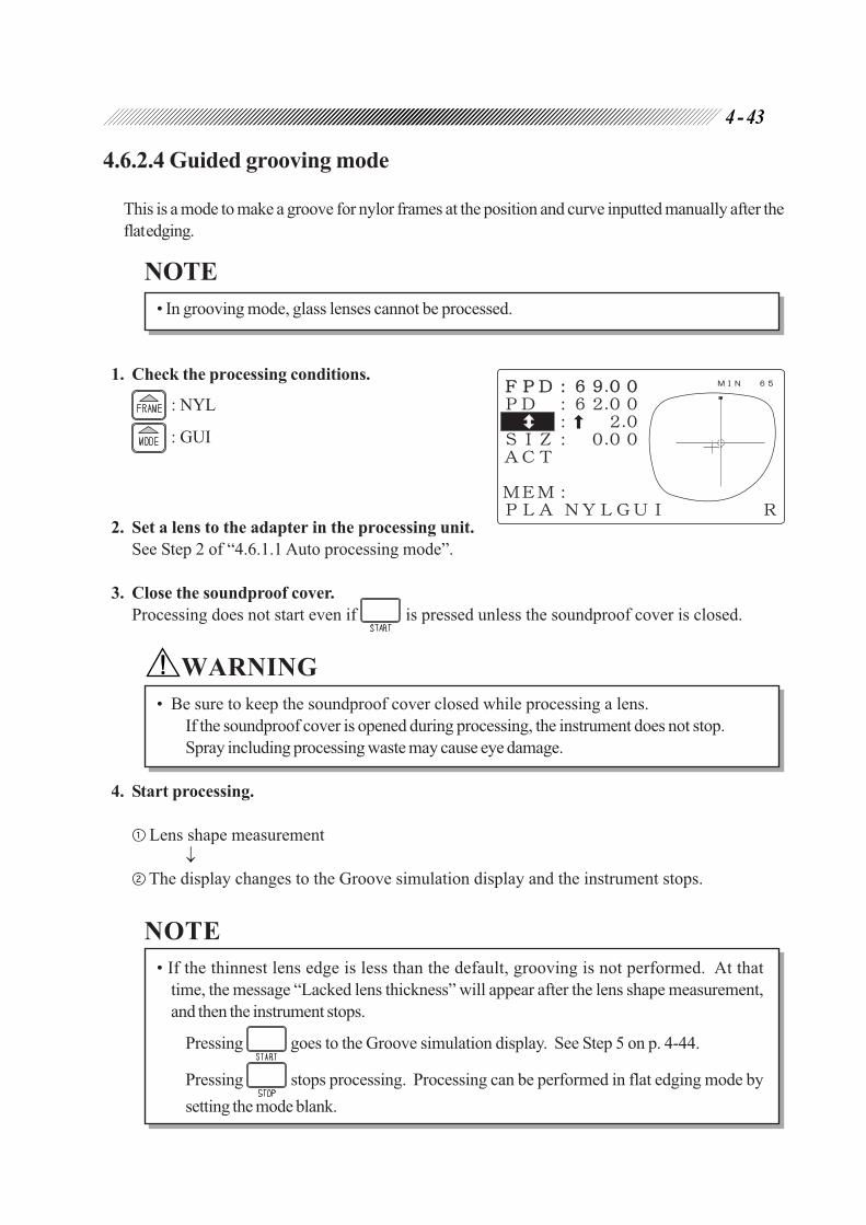
4 - 43
4.6.2.4 Guided grooving mode
This is a mode to make a groove for nylor frames at the position and curve inputted manually after the
flat edging.
NOTE
• In grooving mode, glass lenses cannot be processed.
1. Check the processing conditions.
: NYL
: GUI
2. Set a lens to the adapter in the processing unit.
See Step 2 of “4.6.1.1 Auto processing mode”.
3. Close the soundproof cover.
Processing does not start even if is pressed unless the soundproof cover is closed.
WARNING
• Be sure to keep the soundproof cover closed while processing a lens.
If the soundproof cover is opened during processing, the instrument does not stop.
Spray including processing waste may cause eye damage.
4. Start processing.
Lens shape measurement
The display changes to the Groove simulation display and the instrument stops.
NOTE
• If the thinnest lens edge is less than the default, grooving is not performed. At that
time, the message “Lacked lens thickness” will appear after the lens shape measurement,
and then the instrument stops.
Pressing goes to the Groove simulation display. See Step 5 on p. 4-44.
Pressing stops processing. Processing can be performed in flat edging mode by
setting the mode blank.

4 - 44
5. Simulate the groove section at each point of
the outline on the display.
: The sectional view position line rotates
counterclockwise.
: The sectional view position line rotates
clockwise.
To stop the line movement, press
or again.
: The sectional view position line jumps
to the point that the lens edge is thinnest
( ) and thickest ( ) alternately.
6. Adjust the groove position.
(a) Changing the groove position only at the part that the edge is thick
1) Align the cursor to G CRV.
2) Change the groove curve value to move the
groove position toward the front or rear
surface of the lens.
: The groove curve turns sharp.
: The groove curve turns slight.
As the curve value is changed, the groove
position moves from the edge thinnest point
as the base (The ratio 5:5 will be
maintained). The shifted amount of the
groove is the maximum at the lens edge
thickest point. Change the groove curve,
watching the groove sectional view at the
lens edge thickest point.
The curve value with the “A” mark on the head shows that it is a computer-calculated value. This
value produces the same groove curve that is processed in auto grooving mode.
The groove curve
turns slight.
The groove curve
turns sharp.
<Convex lens>
The groove curve
turns slight.
The groove curve
turns sharp.
<Concave lens>
Sectional view position line

4 - 45
: The curve of the front base curve (FRNT), rear base curve (REAR), or ratio will be selected.
Specified curve value Front base curve Rear base curve Ratio
(curve profiling (curve profiling
the front surface the rear surface
of the lens) of the lens)
NOTE
• The curve value can only be selected within a range that the groove is on the lens edge.
Therefore, the groove will never be off the edge, and a single-sided groove will never
be produced even though groove curve value is changed.
(b) Changing the position of the whole groove parallel to itself
1) Press to simulate the groove at the point
that the edge is thinnest ( ).
2) Align the cursor to PNT.
3) Change the groove dip point value to move
the groove position toward the front or rear
surface of the lens.
: The groove moves toward the front
surface.
: The groove moves toward the rear
surface.
at the value shows that the groove was
moved toward the front surface. at the
value shows that the groove was moved
toward the rear surface.
e.g. G CRV: A 5.0
PNT : 0.6
This shows that the groove was moved 0.6 mm toward the rear surface parallel to itself
while the groove curve value was 5.0.
NOTE
• In order to avoid the groove being off the lens edge, be sure to watch the simulation at
the thinnest position while changing the value.
As distinct from changing the groove curve value, the groove may go off the lens edge.
T h e g r o o v e
moves toward
the rear surface.
T h e g r o o v e
moves toward
the front surface.

4 - 46
7. Check the groove section.
1) Press to turn off the cursor.
2) Simulate the whole groove to see if the desired
groove is obtained. See Step 5 on page 4-44.
8. Repeat Steps 5 - 7 until the desired groove is
obtained.
9. Start processing.
Press .
Roughing
Finishing
Polishing (Only when is selected by PL4, PLB, or PLB-2R.)
Grooving
Chamfering (Only when is selected.)
Processings are complete. [The Layout display returns.]
* The processing order may change according to the lens material.
10. Take the lens off.
WARNING
• Open the soundproof cover after making sure that the wheels have come to a complete stop.
• Release the chuck by pressing after making sure that the wheels have come to a complete
stop.
If the chuck is released before the wheels have not stopped completely and a lens is
dropped, it may contact the turning wheels and its scattering may cause injury.
NOTE
• When the lens, which is hard to be processed or whose edge is thick, is polished, a part
of the edge may remain unpolished.
In such cases, retouch the lens without changing size compensation value. See “4.7.2
Retouching lenses” (p. 4-60).

4 - 47
4.6.2.5 EX lens grooving mode
This is a mode to flat edge the EX lens and make a groove for nylor frames. In this mode, the groove
is set to the curve of the rear lens surface.
NOTE
• In EX grooving mode, glass lenses cannot be processed.
• Use the lens cup for blocking.
The suction cup cannot hold the convex surface of an EX lens securely enough. The
cup may move during blocking.
1. Check the processing conditions.
: NYL
: EX
2. Set a lens to the adapter in the processing unit.
See Step 2 of “4.6.1.1 Auto processing mode”.
3. Close the soundproof cover.
Processing does not start even if is pressed unless the soundproof cover is closed.
WARNING
• Be sure to keep the soundproof cover closed while processing a lens.
If the soundproof cover is opened during processing, the instrument does not stop.
Spray including processing waste may cause eye damage.
4. Start processing.
Press
Lens shape measurement
The display changes to the Groove simulation display and the instrument stops.

4 - 48
NOTE
• If the thinnest lens edge is less than the default, grooving is not performed. At that time, the
message “Lacked lens thickness” will appear after the lens shape measurement, and then the
instrument stops.
Pressing goes to the Groove simulation display. See Step 5 on page 4-48.
Pressing stops the processing. Processing can be performed in flat edging mode by
setting the mode blank.
5. Simulate the groove section at each point of the outline on the display.
: The sectional view position line rotates counterclockwise.
: The sectional view position line rotates clockwise.
To stop the line movement, press or again.
: The sectional view position line jumps to the point that the lens edge is thinnest ( ) and
thickest ( ) alternately.
[For changing the groove position]
See Step 6 - of “4.6.2.4 Guided grooving mode” (p. 4-44) to change the groove position.
NOTE
• As for the curve value, do not change but leave it as “REAR”.
The specified curve, front base curve, or ratio is inappropriate for proper grooving.

4 - 49
6. Start processing.
Press .
Roughing
Finishing
Polishing (Only when is selected by Type PL4, PLB, or PLB-2R.)
Grooving
Chamfering (Only when is selected.)
Processings are complete. [The Layout display returns.]
* The processing order may change according to the lens material.
7. Take the lens off.
WARNING
• Open the soundproof cover after making sure that the wheels have come to a complete stop.
• Release the chuck by pressing after making sure that the wheels have come to a complete
stop.
If the chuck is released before the wheels have not stopped completely and a lens is
dropped, it may contact the turning wheels and its scattering may cause injury.
NOTE
• When the lens, which is hard to be processed or whose edge is thick, is polished, a part
of the edge may remain unpolished.
In such cases, retouch the lens without changing the size compensation value. See
“4.7.2 Retouching lenses” (p. 4-60).

4 - 50
4.6.3 Other processings
4.6.3.1 Processing for frame changing
1. Trace new frames.
2. Call up the traced data.
Press .
The traced outline of the frames will appear
on the display.
3. Establish the frame changing mode.
Press .
FC will appear at the bottom right of the display.
NOTE
• Set the layout mode to ACT (Active).
If the passive mode or bicocal mode is selected, the simple frame changing mode is
established and outlines are not overlaid.
• While the frame changing mode is active, does not function.
4. Block a lens with a lens cup.
1) With lenses fit in frames, mark the optical
centers and horizontal direction with a
lensmeter.
2) Remove the lenses from the frames.
3) Block the convex surface of the lens with a
lens cup, using a centering device.

4 - 51
5. Set the lens to the pattern setting unit while
pressing the white button.
Align the top mark on the cup with the direction
of the white button.
6. Trace the lens in the same manner as Steps 2
- 4 of “4.3.2 Tracing pattern”.
After tracing is completed, the traced lens
outline (thick line) will appear over the frame
outline (thin line) on the display.
7. Set processing conditions and enter layout
data (PD, ).
See “4.4.1 Selecting processing conditions and
inputting layout data” (p. 4-11).
8. Make sure that the lens size is large enough
for the frame.*11
Check if the whole frame outline (thin line) is
within the lens outline (thick line).
*11 If the lens size is not large enough for the frame, it is possible to move the location of the frame
outline into the lens outline by changing the PD or value. The finished lens, however, will
not follow prescription.
Thin lineThick line
White button
4 - 52
9. Remove the lens with the lens cup from the pattern setting unit.
10. Process the lens.
The processing will not start if it is judged that the lens size is not enough for processing in the
lens shape measurement*12.
11. Press to switch the side (R or L), and process the lens of the other side in the same
manner as Steps 4 - 10.
12. After both lenses are processed, press to exit from the FC mode.
[Simple frame changing mode]
When the lens size is large enough for the new frame, there is no need of lens tracing. Skip Steps
5, 6, 8 and 9 so that trouble for lens tracing can be saved. The ICE-9000 blocks a lens whose
frame is to be changed with a lens cup at the rim center. Pressing in the FC mode establishes
the simple frame changing mode automatically. This is because the ICE-9000 has already checked
that the lens size is sufficient and outlines do not need to be overlaid by the LE-9000.
*12 In the frame changing mode or simple frame changing mode, a lens can be measured even if the
lens has no extra margin. This is because the feelers measure the lens shape at 1.5 mm inside of
the traced outline.

4 - 53
4.6.3.2 Processing half-eye lenses
When the distance from the blocking point to
the position of edge-to-be is short and the lens
adapter or lens clamp may contact with the
wheels, the mark of the optical center will
change from to .
If indicates, replace the lens adapter, lens
clamp and lens cup with the ones for half-eye lenses
by the following procedure.
NOTE
• To process a half-eye lens, the following accessories are required.
Required accessories:
a half-eye adapter, a half-eye lens clamp, a half-eye lens cup,
a double-coated adhesive tape for half-eye lens, and a hex driver
• When the traced frame has enough vertical diameter, the standard adapter can be used
by blocking the lens at the rim center in the passive mode.
1. Replace the adapter with that for half-eye lenses.
1) Remove the standard adapter.
Loosen the set screw on the standard adapter
with a provided hex driver to remove the
adapter.
2) Set the half-eye lens adapter.
Align the kerf on the adapter with the pin
on the shaft, making sure that the set screw
is facing toward you to fit the adapter. Then
tighten the set screw to fix it.
2. Replace the lens clamp with that for half-eye
lenses.
1) Loosen the set screw on the standard clamp
to remove it.
Remove the lens clamp after loosening the
set screw with the hex driver.
2) Fit the half-eye lens clamp securely to the
shaft, and fix it with the set screw.
Fit the lens clamp, aligning its kerf with the
pin on the shaft securely.
Pin
Set screw
Standard adapter
Kerf Set screw
Half-eye lens adapter
Standard clamp
Half-eye lens clamp

4 - 54
Color of lens cup Suitable lens
Blue
Front curve 5 or less
(Suitable for flat lenses such as an
aspheric negative lens)
White Front curve 5 to 9
Pink
Front curve 9 or more
(Suitable for a lens that has a sharp
front curve)
Cut off
Cut off
Double-coated adhesive tape
for half-eye lens
Conventional double-coated adhesive tape
3. Block the lens with the half-eye lens cup.
1) Stick a provided double-coated adhesive
tape for half-eye lens to the half-eye lens
cup.
(Double-coated adhesive tape for half-eye
lens is supplied only for the NIDEK type.)
If you use the conventional double-coated
adhesive tape, cut off the excess part along
the edge of the cup.
If the lens is processed without cutting the
excess part, the feeler will put on the tape in
the lens shape measurement and correct
processing may not be performed.
2) Block the lens with the half-eye lens cup.
NOTE
• Use the half-eye lens cup that is suitable for the front curve of a lens (only for the
NIDEK-type cup).
An axis shift may occur if a half-eye lens
cup that is not suitable for the front
curve is used.
4. Set the lens to the adapter.
See Step 2 of “4.6.1.1 Auto processing mode”.
NOTE
• Align the top mark on the lens cup with the top mark on the adapter to fit the leap cut into the
adapter.
If not, the adapter cannot hold the lens cup securely.
5. Close the soundproof cover and press .
The “Use chuck for half-eye lens” message will appear.
Make sure that the lens adapter, lens clamp and lens cup are the ones for half-eye lens. If not,
replace them after returning to the Layout display by pressing .
NOTE
• Displaying the “Use chuck for half-eye lens” message can be disabled.
When the lens adapter and lens clamp for half-eye lens are used all the time, the
operation will be smooth without a stop of the instrument. See “5.2 Parameter Settings”
(p. 5-2).

4 - 55
WARNING
• Be sure to keep the soundproof cover closed while processing a lens.
If the soundproof cover is opened during processing, the instrument does not stop.
Spray including processing waste may cause eye damage.
6. Start processing.
Press .
NOTE
• After processing a half-eye lens, be sure to replace the adapter and the lens clamp with
the standard ones.

4 - 56
4.6.3.3 Polishing (Type PL4, PLB, and PLB-2R)
This is a mode to polish the lens edge to save your time required to buff the lens edge after finishing.
Set “POL” by pressing before starting
processing with .
NOTE
• Glass lenses cannot be polished.
• For Type PL4, polishing cannot be performed in beveling.

4 - 57
4.6.3.4 Chamfering
Before processings are complete, chamfering can be performed.
Select the SFB mode by pressing before
starting processing with .
The LED beside lights up, and or is
shown on the display panel.
Both lens edges are chamfered.
Rear lens edge is chamfered.
For setting or and safety bevel amount, see “8.13.1 Setting of SFB mode and chamfering
amount” (p. 8-31).
[Addition of chamfering]
When the “To add safety bevel” parameter is set to “Exec”, chamfering can be additionally performed
after lens processing.
However, as well as retouching, this cannot be performed such as when removing the suction
cup, switching R/L and reading other frame data.
1) Set the SFB mode by pressing .
The LED beside lights up.
2) Set a lens to the adapter in the processing
unit.
Align the top mark (•) on the suction cup
with that of the adapter and insert the suction
cup firmly. Then press to fix the lens.
3) Close the soundproof cover and press
or .
Chamfering is performed.
After retouching, chamfering is performed.
NOTE
• If the chamfering has been performed in the first processing, retouching of safety bevel
can be performed by the same procedure.
• When the SIZ value is subtracted with , additional chamfering and retouching of safety
bevel cannot be performed.
Top mark Top mark

4 - 58
4.6.3.5 Glass soft processing
This is the processing method to perform the
roughing process more precisely.
Even though the processing time is extended a
little, lens breakage is prevented.
When glass lenses are broken during processing,
select the soft processing mode to prevent them
from breaking.
NOTE
• The soft processing mode is effective only when “GLS” is selected for the lens material.
• The soft processing mode cannot be selected in the bifocal mode.
• When glass lenses are broken in the half-eye lens processing, use a white lens cup or
the optional pliable cup.
[Setting the soft processing mode at all times]
Set the “GLS soft grind” parameter to “Exec” on the Parameter exchange mode screen. See
“5.2 Parameter Settings” (p. 5-2).
When the lens material is set to “GLS”, the soft processing mode is automatically turned on.
To switch off (or on) the soft processing mode temporarily, pressing for about 1 second
produces a beep and turns on or off the soft processing mode.
[Setting the normal processing mode and soft processing mode on the Layout display]
Regardless of the parameter setting, pressing for about 1 second produces a beep and
turns on or off the soft processing mode.
When the soft processing mode is on, “SOFT” is displayed at the upper part of the Layout
display.
Displayed only when the soft processing
mode is selected.

4 - 59
4.6.3.6 Inputting the frame tilt angle in flat edging
To increase the finished PD accuracy, correction is made using the frame tilt angle measured
during tracing. For nylor or two-point frames, however, the frame tilt angle cannot be measured
because the pattern is traced. The frame tilt angle is entered for a corrective calculation to
increase the finished PD accuracy in flat edging.
This parameter is factory set to 5.0°. For frames that are very tilted, it is recommended to enter
the frame tilt angle by the following procedure and then set the value back to the original after
processing.
1. Roughly measure the frame tilt angle using a
piece of graph paper.
2. Call up the MENU display.
Press .
3. Call up the PD adjustment display.
After moving the cursor to “PD adjustment”,
press .
4. After moving the cursor to “Frame Tilt
Angle (flat)”, enter the frame tilt angle using
or .
Range: 0.0 to 30.0°, step: 0.5°
5. Go back to the MENU display.
Press .
6. Go back to the Layout display.
Press twice.
Frame tilt angle

4 - 60
4.7 Checking the Lens Size
Check the lens size after processing is completed. If the lens is too large, retouch it to correct the
size.
4.7.1 Checking the lens size
Fit the lens in the frame and measure the gap at the rim joint.
NOTE
• Do not remove the cup yet, otherwise the
lens cannot be retouched.
4.7.2 Retouching lenses
If the finished size of the lens is too large to fit into the frame, perform retouching.
1. Change SIZ with .
No other values than SIZ can be changed.
Reference guide for size correction:
Subtract one-third of the gap size at
the rim joint from SIZ.
e.g. If the gap is 1 mm:
1/3 × 1 (mm) = approx. 0.3 (mm)
Subtract 0.3 from SIZ.
2. Set the lens to the adapter.
Align the top mark (•) on the cup with that of
the adapter to reset the lens. Then, press
to fix the lens.
3. Start retouching.
Close the soundproof cover and press .
4. After the process, check the lens size again.
If the finished lens is still large, retouch it again.
Top mark Top mark
Gap

4 - 61
NOTE
• In the retouching process, reducing the lens size in 0.5 mm or more may lessen its vertical
width.
Therefore, in the trial processing, process a lens with its size 3 mm larger. In the
actual processing, do not perform retouching but follow the instructions below
beginning with roughing.
1) Change the size value.
2) Press twice.
3) Press to start processing.
• Retouching cannot be performed such as when removing the suction cup, switching R/
L, or reading other frame data.
[Retouching of groove]
Retouching of groove can be performed by the same procedure with “[Addition of grooving]”
(p. 4-38).
If the SIZ value has been changed, retouching of groove cannot be performed.
Moreover, if “GUI” is selected, any other changes than the groove depth and width to larger size
cannot be made on the Simulation display.
[Retouching of safety bevel]
Retouching of safety bevel can be performed by the same procedure with “[Addition of
chamfering]” (p. 4-57).
If the SIZ value has been changed, retouching of safety bevel cannot be performed.
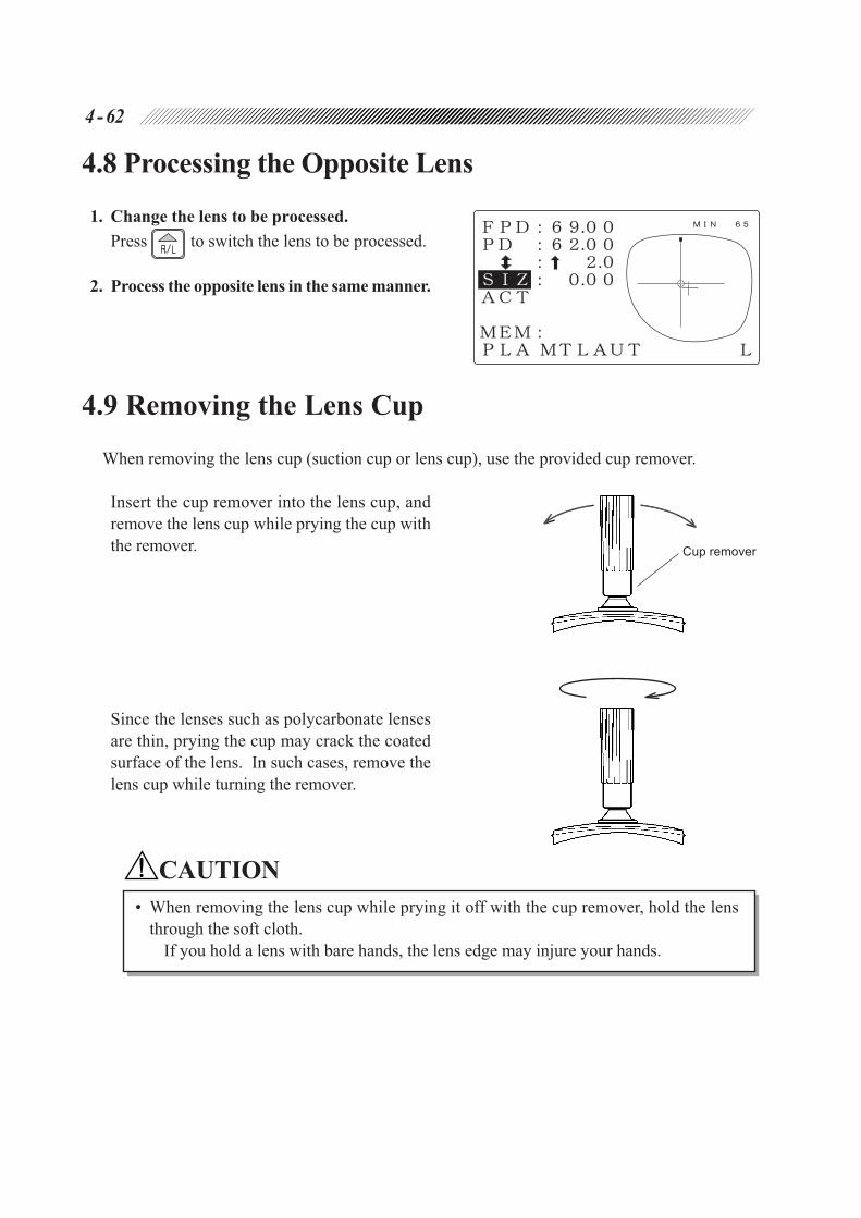
4 - 62
Cup remover
4.8 Processing the Opposite Lens
1. Change the lens to be processed.
Press to switch the lens to be processed.
2. Process the opposite lens in the same manner.
4.9 Removing the Lens Cup
When removing the lens cup (suction cup or lens cup), use the provided cup remover.
Insert the cup remover into the lens cup, and
remove the lens cup while prying the cup with
the remover.
Since the lenses such as polycarbonate lenses
are thin, prying the cup may crack the coated
surface of the lens. In such cases, remove the
lens cup while turning the remover.
CAUTION
• When removing the lens cup while prying it off with the cup remover, hold the lens
through the soft cloth.
If you hold a lens with bare hands, the lens edge may injure your hands.

4 - 63
4.10 Treatment after Daily Use
1. Clean the processing unit.
Follow Steps 1 - 4 in “8.1 Wheel Dressing” to water the processing unit and wash out the
processing wastes with a brush.
CAUTION
• Be careful not to let water go into the inside of the instrument.
It may cause malfunction of the instrument.
NOTE
• Clean the processing unit after each use of the day. Be sure to clean it on the day that the
instrument is used.
If it is left for several days after use, the processing waste becomes settled and hard to
remove.
2. Turn the power OFF.
3. Perform after-use daily checks. See “4.11.2 Daily check after use” (p. 4-65).
4. Close the cover of the tracing unit.
5. Store accessories in a customary place.
Wipe the dirt on the accessories off and store them in a customary place to avoid possible loss
or breakage.

4 - 64
4.11 Daily Checks
4.11.1 Daily check before use
Check the followings before each use of the day.
It is recommended to provide a check list to make sure everything is checked.
A. Is the wheel proper?
Check if there is no fracture, crack, or flaw on the wheel.
CAUTION
• If a fracture, crack or flaw is found on the wheel, stop using the instrument and contact
NIDEK or your authorized distributor.
Keep using the instrument may break the processing wheel and its broken pieces may
injure the personnel.
B. Is there enough water in the tank ?
The water should be filled up to 70 - 80% of the tank.
NOTE
• If water is very dirty, replace the water. See “8.2 Replacing the Water and Filter” (p. 8-5).
With dirty water, the lens edge may not be well polished.
C. Does the stocking filter have enough free space?
If it is filled with processing wastes, replace the stocking filter. See “8.2 Replacing the Water
and Filter” (p. 8-5).
D. Does the layout display appear when the power is turned ON?
1) Turn ON the power.
2) Make sure that the Layout display appears without an error.
E. It is recommended to calibrate the tracing unit.
See “8.14 Tracer Calibration” (p. 8-35).
F. Confirm that wash water (for the inside wall of the processing chamber) and cooling water
(for the wheels) flow properly.
1) Set dressing mode.
2) Press to confirm that wash water and cooling water are flowing.
CAUTION
• Take care not to get spray into your eyes.
Spray including processing waste may cause eye damage.
If wash water or cooling water do not flow, confirm that the PUMP1 and PUMP2 hoses and the
power cords are properly connected to the main unit.

4 - 65
4.11.2 Daily check after use
Check the followings after every use each day.
It is recommended to provide a check list to make sure everything is checked.
A. Is the power turned OFF?
B. Is the processing unit well cleaned?
C. Is there any stain or breakage on the main body?
D. Do all accessories have no breakage?
For accessories, see “§10 ACCESSORIES”.

4 - 66
4.12 Periodical Check
It is recommended to perform the periodical inspection every two years to use the instrument for a long
time under a normal condition. On the periodical inspection, performance check of the whole system,
etc. and replacement of maintenance parts are done.
If the inspection is required, contact NIDEK or your authorized distributor.
* Replace the wheel every two years or after processing of five thousand lenses. Contact NIDEK
or your authorized distributor. However, the number of lenses is referred only as a guide, so
replacement at earlier period may be needed under such conditions that hard lenses have been
processed in a row or numerous high-strength minus lenses have been processed.
Be careful not to dress or edge glass lenses with the wheel for plastic lenses. If the wheel has
been damaged because of such carelessness, it will extremely shorten the lifetime of the wheel.
Periodical maintenance item Maintenance contents
Belt for wheel rotation
Check the tension of the belt, and stretch the belt again
if the tension is below standard.
Replace the belt if it is damaged or deteriorates.
Wheel*
Check if there is no deterioration on the processing
performance.
Replace the wheel if its processing surface is frayed,
which will be a problem in practical use.
Spindle unit Put more grease on the waterproof seal.
Replace the waterproof seal if it deteriorates.
Chamber
Check if there is no crack, fracture, deterioration, or
problem on the chamber.
Replace the chamber if there is a problem.
CarriagePut more grease on the lens clamp axis, Y axis, and X
axis, or lens rotating axis of the carriage.
Interior of the instrumentCheck if there is no waste inside of the instrument.
Clean the interior if wastes are scattered.
Feedwater/Drain pipes
(including feedwater pipes
in the instrument)
Check if there is no crack, deterioration, or clogging on
the feedwater pipes and drain pipe visually and by
touch.
Replace the pipe if there is a problem.

5.1 Process Counter
This function displays the count for lenses that have been processed since production for each
lens material. The counts for polished, grooved, and chamfered lenses are also displayed.
1. Call up the MENU display.
Press .
2. Select “Process counter”.
Align the pointer ( ) to “Process counter” and
press .
The process count for each material will be
shown.*1
To check the chamfered lens count and total
processed count, move the pointer ( )
downward with .
3. Go back to the MENU display.
Press .
4. Go back to the Layout display.
Press twice.
*1 The process counter of high index plastic, acrylic resin or trivex lenses is included in Plastic. If
it is optionally set to process high index plastic lenses with the glass roughing wheel, the
process counter of high index plastic lenses is included in Glass.
§5OTHER FUNCTIONS

5 - 2
5.2 Parameter Settings
This function sets each parameter according to the operator’s use.
1. Call up the MENU display.
Press .
2. Call up the Parameter exchange mode
display.
Press again.
3. Select the item whose parameter needs to be
changed.
Align the pointer ( ) to the desired item with
or .
The setting items and their contents are shown
on the following pages.
4. Change the setting.
Change the setting with or .
5. Go back to the Layout display.
Press .

5 - 3
[Parameter items and the setting contents]
1) Size preset (PLA, MTL) : ± .
2) Size preset (PLA, CEL or ZYL) : ± .
3) Size preset (GLS, MTL) : ± . (not function for Type PLB)
4) Size preset (GLS, CEL or ZYL) : ± . (not function for Type PLB)
Factory setting: +0.00 [mm]
Initial settings of size corrective value for each combination of lens material and frame material.
(Available setting value: –9.95 - +9.95)
Lens materials such as high index plastic, polycarbonate, acrylic resin, and trivex are
regarded here as plastic.
5) Initial value of FPD : ± .
Factory setting: +70.0 [mm]
Sets the initial FPD value.
6) Initial value of PD : ± .
Factory setting: +62.0 [mm]
Sets the initial PD value.
Press or to input any PD value. The set value appears first on the Layout
display.
7) Layout preset : ± .
Factory setting: +2.0 [mm]
Presets the height of the optical center. Set the value as the height of the optical center from the
rim center. When inputting each data of the lens layout, this value is automatically set at
(could be PD or BT ). This setting is not effective for eye point layout.
8) Measure in flat edge : None, Exec
Factory setting: Exec
Selects whether to measure the lens shape during flat (rimless) edging. When “Exec” is se-
lected, the lens shape will be measured (front surface only) before roughing to check if the lens
size is enough.
Lenses can be processed without measuring the lens shape by selecting “None”. Regard-
less of the setting, the lens shape will be measured when “To add safety bevel” is set to
“Exec”, or chamfering and/or grooving is performed.
9) Grind by mirror image : R, L
Factory setting: R
When both rims are traced, the mirror image of right or left rim, will be used as the lens
shape data of the other side. This parameter decides which is the base side (right or left).
In spite that shape is mirrored, the size (circumference) will not be mirrored, but comply
with the outline for the respective side.

5 - 4
10) Ext. interface: None, STD., RS232, LAN, ExLAN, MGNET, BK/LE, NAVIS, DVI, VCA-A, VCA-B
Factory setting: NAVIS
Selects whether or not to communicate with an external instrument and sets the communication
format. Only when “None” is selected, the memory function becomes available.
STD.: NIDEK standard format. This is used to connect a NIDEK instrument with the edger.
The edger is able to interface with the NIDEK LT-200, LT-700, LT-800, or LT-900.
RS232: RS-232C standard format
LAN: LAN format
ExLAN: Extended specifications for the LAN format
MGNET: Format for the MEGANET terminal
BK/LE: Communication format for the one-to-one connection with the NIDEK INTELLI-
GENT BLOCKER ICE-2000/ICE-9000/ICE mini
NAVIS: Format for the NAVIS-EC terminal
DVI: DVI format
VCA-A: VCA format
VCA-B: VCA format. In VCA (OMA) communication, the received circumference is not
used but the 3-D circumference is recalculated from the frame curve for processing.
11) Layout memory : None, Exec
Factory setting: Exec
Selects whether or not to call layout data as well as the lens shape when calling the data with
the memory function.
In the following display, data in the area show that it can be called up to the display
at each setting.
<When setting at “None”> <When setting at “Exec”>
12) Bar Code memory : None, Exec
Factory setting: None
Selects whether or not to use an optional barcode scanner to call up the data from the internal
memory. By connecting the barcode scanner, it will become possible to store 500 pieces of
frame data.
13) Half eye check : None, Exec
Factory setting: Exec
Selects whether or not to indicate the message suggesting cup replacement and to stop the
instrument for a lens with short vertical diameter.
Set the parameter to “Exec” except when the half-eye lens chucking is successively
performed.

5 - 5
14) Data Transfer : NON, VALUE, MATER, POLIS, BF, ALL
Factory setting: NON
Selects the kinds of data that the edger does not accept when receiving the data from an
external device. The selected data in the parameter will be transmitted, but not accepted by
the edger. On the edger side, the previous data remains active even after the data transmission.
Only when the communication specifications is special and the “Ext. interface” parameter is set
to “DVI”, this setting is available.
NON: No received data will be disabled; All the data will be recognized and shown on the
display.
VALUE: All the data of lens layout are disabled.
MATER: The data of lens material is disabled.
POLIS: Only the data of “POL (Polishing)” is disabled.
BF: Only the data of “BIF (bifocal) mode” is disabled.
ALL: All the data of lens layout and processing conditions are disabled.
15) BF ChuckLayout Side : ± mm
(If a minus value is input, the lens will be processed with its blocked point at the specified
value outside from the top line center of segment.)
Factory setting: –5 [mm]
16) BF ChuckLayout Height : ± mm
Factory setting: +5 [mm]
Sets the lens layout for blocking the bifocal lens. Specify the shifted values from the top line
center of the segment in blocking the bifocal lens. When using the NIDEK Centering device,
Model CE-1, leave the setting at the factory setting (5 mm outside, 5 mm up) and never change
it.
17) TILT Function : None, Exec
Factory setting: None
Selects whether or not to use the tilting function in the guided processing mode. If a lens has an
extreme difference in width between the edge thickest point and thinnest point, the appearance
of the mounted lenses will get better by tilting the bevel.
18) Reverse PC Grind : None, Exec
Factory setting: None
Selects whether or not to use the roughing function while changing the lens rotation direction to
improve the axis accuracy of polycarbonate lenses. To process a lens with greater accuracy,
select “Exec”. When “Exec” is selected, however, the processing waste may become bigger
or the lens edge may become rough after processing.
19) Reverse GLS Grind : None, Exec
Factory setting: None
Selects whether or not to use the roughing function which changes the lens rotation direction to
reduce the processing time of a glass lens. To put a premium on the processing time reduction,
set this parameter to “Exec”. Setting this parameter “Exec” roughly processes a lens by auto-
matically changing the position to be contacted with the wheel from side to side so that the
roughing wheel will not be worn on one side.

5 - 6
20) Meas. after roughing : None, All, PLA
Factory setting: None
Setts function that remeasures the lens shape after roughing.
None: After roughing, the lens shape is not remeasured.
All: Except when the lens material is set to “GLS” (glass), the lens shape is remeasured
after roughing.
PLA: When the lens material is set to “PLA” (plastic) or “HPL” (high-index plastic), the lens
shape is remeasured after roughing.
Remeasuring the lens shape after roughing prolongs the processing time; however, the problem
that a bevel or groove is displaced from the desired position due to distortion produced on a
lens during roughing can be improved.
Regardless of this setting, the lens shape will not be measured when both the “Measure in
flat edge” parameter and the “To add safety bevel” parameter are set to “None”, and
neither chamfering nor grooving is performed in the flat edging.
21) GLS soft grind : None, Exec
Factory setting: None
Selects whether or not to perform the soft processing of a glass lens as default.
When this parameter is set to “Exec” and “GLS” is selected for the lens material, the soft
processing mode is automatically turned on. In soft processing mode, the processing sound is
reduced and a lens becomes hard to break during processing.
22) Maintenance message: Tank, Wheel, Both, None
Factory setting: Both
Sets the function that displays a maintenance message that prompts the user to replace the
processing water or dress the wheel.
Tank: Immediately after processing of 70 lenses, “Please Clean Tank & Pump and Replace
filter” is displayed.
Wheel: Immediately after processing of 2000 lenses, “Wheel Dressing Reminder/ Dress bevel
and polish wheels/ See Operator’s Manual” is displayed.
Both: Both settings of the above Tank and Wheel are enabled.
None: Both settings of the above Tank and Wheel are disabled.
23) To add safety bevel : None, Exec
Factory setting: None
Selects whether or not to perform the chamfering additionally in the state of retouching after the
process. When “Exec” is selected, the lens shape will be measured before processing so that
the chamfering and/or grooving can be performed.
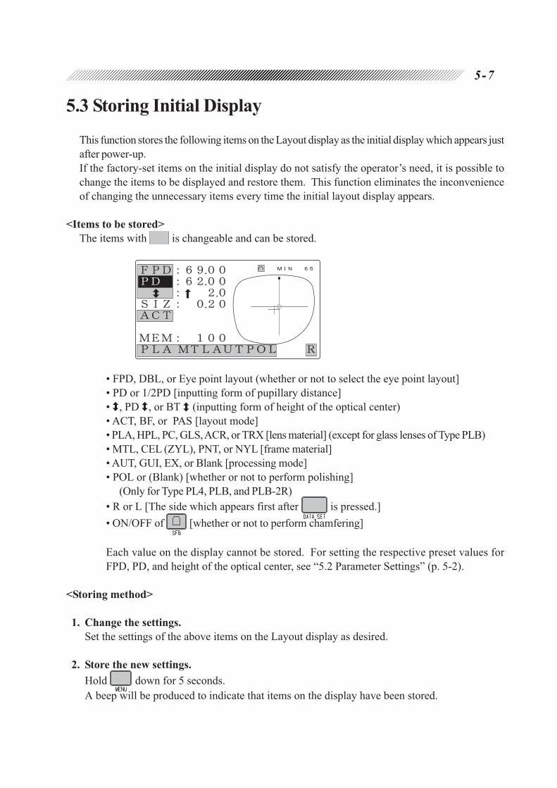
5 - 7
5.3 Storing Initial Display
This function stores the following items on the Layout display as the initial display which appears just
after power-up.
If the factory-set items on the initial display do not satisfy the operator’s need, it is possible to
change the items to be displayed and restore them. This function eliminates the inconvenience
of changing the unnecessary items every time the initial layout display appears.
<Items to be stored>
The items with is changeable and can be stored.
• FPD, DBL, or Eye point layout (whether or not to select the eye point layout]
• PD or 1/2PD [inputting form of pupillary distance]
• , PD , or BT (inputting form of height of the optical center)
• ACT, BF, or PAS [layout mode]
• PLA, HPL, PC, GLS, ACR, or TRX [lens material] (except for glass lenses of Type PLB)
• MTL, CEL (ZYL), PNT, or NYL [frame material]
• AUT, GUI, EX, or Blank [processing mode]
• POL or (Blank) [whether or not to perform polishing]
(Only for Type PL4, PLB, and PLB-2R)
• R or L [The side which appears first after is pressed.]
• ON/OFF of [whether or not to perform chamfering]
Each value on the display cannot be stored. For setting the respective preset values for
FPD, PD, and height of the optical center, see “5.2 Parameter Settings” (p. 5-2).
<Storing method>
1. Change the settings.
Set the settings of the above items on the Layout display as desired.
2. Store the new settings.
Hold down for 5 seconds.
A beep will be produced to indicate that items on the display have been stored.

5 - 8
5.4 Storing and Calling Up the Traced Data
The edger is provided with a memory function, which stores traced data and lens layout data in its
memory and calls them up whenever necessary. By storing a repetitive lens outline as a standard
data and calling it up with the function, an operator does not have to trace the same lens for each
processing and can save required time for lens processing. Besides, even though a frame is not
handy, it is possible to process the lens as soon as it is ready to be processed. The memory holds
up to 100 sets of the traced and layout data at most. The use of an optional barcode scanner
extends the storable number of data up to 500 sets of data.
CAUTION
• When a lens is processed by the data called up from the memory, perform it after
checking the traced outline on the display.
When the called data is abnormal, the error code (Error 0906) will appear. Restore
the data without processing.
NOTE
• Concurrent use of communication function and memory function is impossible. Only
when “Ext. interface” is set at “None”, the memory function becomes available.
• The stored data is battery-protected even though the power is turned OFF.
Since this battery is a rechargeable type, the battery becomes empty and the stored
data may be gone if the instrument is not used for a long time (about one month) or
soon after the instrument is purchased. In this case, turn ON the power of the main
body and charge the battery. For full-charging, it is necessary to keep powering ON
for 15 hours.
If the power is supplied to the instrument for one hour or more everyday after full-
charging, the battery becomes almost fully charged. If the instrument is used for a
short time, keep the power of the instrument ON for several hours once a month.
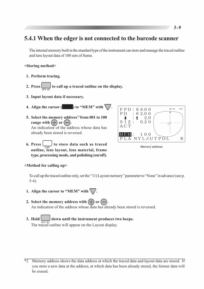
5 - 9
5.4.1 When the edger is not connected to the barcode scanner
The internal memory built in the standard type of the instrument can store and manage the traced outline
and lens layout data of 100 sets of frame.
<Storing method>
1. Perform tracing.
2. Press to call up a traced outline on the display.
3. Input layout data if necessary.
4. Align the cursor ( ) to “MEM” with .
5. Select the memory address*2 from 001 to 100
range with or .
An indication of the address whose data has
already been stored is reversed.
6. Press to store data such as traced
outline, lens layout, lens material, frame
type, processing mode, and polishing (on/off).
<Method for calling up>
To call up the traced outline only, set the “11) Layout memory” parameter to “None” in advance (see p.
5-4).
1. Align the cursor to “MEM” with .
2. Select the memory address with or .
An indication of the address whose data has already been stored is reversed.
3. Hold down until the instrument produces two beeps.
The traced outline will appear on the Layout display.
*2 Memory address shows the data address at which the traced data and layout data are stored. If
you store a new data at the address, at which data has been already stored, the former data will
be erased.
Memory address

5 - 10
5.4.2 When the edger is connected to the barcode scanner
By connection of the edger to the optional barcode scanner, the barcode memory function, which
stores traced outline and lens layout data for a maximum of 500 sets of frame, becomes available.
The read barcode number is stored as the managing number of the data. The barcode numbers
allow easy management of frame.
CAUTION
• The barcode memory function cannot be used concurrently with the memory function
by memory address of the standard specification.
• When the instrument was changed from the standard specifications to the barcode
specification, all the data stored with memory address will be erased.
NOTE
• Make sure that the barcode scanner is connected to the connector for the barcode on
the rear panel of the instrument (see p. 3-1).
<Storing method>
1. Perform tracing.
2. Press to call up a traced outline to the display.
3. Input each data of lens layout as necessary.
4. Read the corresponding barcode of the
frame to be stored.
The display will change to the Barcode display,
and the read barcode will be shown. *3
5. Press to store the traced outline, lens
layout, lens material, frame type, and the
processing mode.
After all data have been stored, the Layout display will return.
NOTE
• To cancel the data storage to the memory after reading the barcode, press .
*3 When the data is additionally stored with the barcode number whose data has already been
stored, the former data will be erased.

5 - 11
<Method for calling up>
To only store the traced outline and not storing the lens layout data, set the “Layout memory” parameter
at “None” in advance (see p. 5-4).
1. Read the barcode of the frame whose data
to be called up.
The display will change to the Barcode display,
and the read barcode will be shown.
2. Press to call up the data.
After calling up the data, the corresponding
traced outline to the barcode will appear on the
display.
NOTE
• To cancel the data call from the memory after reading the barcode, press .

In the event that the instrument does not work correctly, correct the problem according to the
following table before contacting NIDEK or your authorized distributor.
* In the event that the symptom cannot be solved by these suggestions above, contact NIDEK or your
authorized distributor.
Symptom Action
The display is not shown though the
power is turned ON.Replace fuses. See "8.4 Replacing Fuses" (p. 8-12).
The stylus cannot be set in the groove of
frames.
Perform the semiauto tracing. See "4.3.1.3
Semiauto tracing" (p. 4-5).
The stylus comes off the groove of frame
during tracing, and tracing stops. The
lamp beside keeps blinking.
Press to return the stylus to its original
position, and trace frames again. If the stylus comes
off because the frames are sharply warped, set only
one rim and hold the other rim to trace.
See "4.3.1.4 Tracing goggle type frames" (p. 4-6).
Retracing starts automatically and the
lamps beside and blink for a
few seconds. Pressing does not
read the traced data.
There is difference in circumference between the
right and left rims. (Difference: 1 mm or more)
Trace a single rim and then edge a lens.
The message "Use chuck for half-eye
lens" appears and the instrument stops.
Use the adapter set for half-eye lens. See "4.6.3.2
Processing half-eye lens." (p. 4-53).
During the lens shape measurement, the
display changes to the Bevel simulation
display, and a part of the traced outline
blinks.
The size of the set lens is not large enough to be
processed into the selected lens outline. The
blinking line indicates that the lens diameter is not
enough for the part.
Press to stop processing, and use a larger lens
or change the lens layout.
Processing does not start though
is pressed.
A beep will be produced.
Processing does not start in a state that the
soundproof cover is open. Close the soundproof
cover. The instrument is trying to process the same
side of the lens. Press to change the indication
R or L to process the opposite lens.
The memory function cannot be used. Set the parameter "10) Ext. interface" to "None".
Error code appears and the instrument
stops.
A problem occurs in the instrument.
Press to reset the instrument.
If the error code still appears, contact NIDEK or your
authorized distributor.
Follow the procedure if the action is described on
the error code table of Appendix B.
§6TROUBLESHOOTING GUIDE

NOTE
• Store the instrument in an environment free from dust and direct sunlight.
Avoid storing instrument in humid surroundings.
• If the instrument will not be used for a long time, unplug the power cable from the wall
outlet.
If settled dust in and on an instrument attracts moisture, it may cause a short circuit
or a fire.
1. Unplug the power cable from the wall outlet.
2. If the instrument will be not used for a long time, drain water in the tank and feedwater
pumps.
3. Shut the cover of the tracing unit and the soundproof cover.
4. Store accessories.
Store them in a customary place such as the drawer of a table to avoid possible loss or breakage.
§7STORAGE

8.1 Wheel Dressing
A clogged wheel requires a longer time for processing and makes the finished size inaccurate. It
is necessary, therefore, to regularly dress the wheels.
CAUTION
• In the dressing mode, the cover sensor is released and the wheels turn with the soundproof
cover open. While dressing, work with special care.
• Be sure to wear protective glasses while dressing the wheel.
Spray including processing waste may damage your eyes.
• Be sure to select a proper dressing stick suited to the wheel type. See p. 3-4 for wheel
combination of each instrument type.
Using an improper dressing stick may damage the wheel and a lens may not be
processed properly.
Roughing wheel for glass lenses Dressing stick for the roughing wheel (orange) WA80K
Finishing wheel Dressing stick for the finishing wheel (white) WA320K
Polishing wheel Dressing stick for the polishing wheel (light blue) WA4000 RH-20
Chamfering wheel Dressing stick for the polishing wheel (white) WA320K
• Never dress the roughing wheel for plastic lenses.
It will damage the wheel for plastic lenses, and as a result, a lens may not be processed
properly any longer.
NOTE
• When processing is not completed within a certain period of time due to clogging of the
glass roughing wheel or finishing wheel, it is stopped and the “Rough Wheel Dressing Reminder”
or “Finish Wheel Dressing Reminder” message appears. According to the message, dress
the wheel.
• Pressing during wheel dressing stops water from the chamber-cleaning nozzle to prevent
the chamber from getting soiled.
If water discharge from the chamber-cleaning nozzle has been stopped accidentally, press
again to resume discharging.
1. Call up the MENU display.
Press .
2. Call up the Wheel dressing display.
Align the pointer ( ) to “Wheel dress-
ing” with and press .
§8MAINTENANCE

8 - 2
3. Open the soundproof cover.
4. Start dressing.
CAUTION
• Apply the end surface of the dressing stick to the wheel, not the corner or the edge.
Otherwise, the wheel may be damaged.
• Hold the dressing stick with both hands.
If the stick is held with one hand, the stick cannot be held strongly enough, the
corner of the stick may collide with the wheel and damage it.
• Hold the dressing stick so that its end is 2 - 3 cm away from your fingers.
If the stick is held closer than this distance, you may contact the wheels and fingers may get
hurt.
• Be sure to replace the dressing stick worn some 4 cm with the new one. Especially, replace
the dressing stick for the polishing wheel when it becomes shorter than 5 cm.
It is hard to hold a shortened dressing stick, and your fingers may get hurt or the wheels
may be damaged.
[Dressing the roughing wheel for glass lenses and the finishing wheel]
1) Press .
Water will run for a few seconds and the wheels will begin to turn at the same time.
2) Wet the dressing stick well with running water.
3) Press to stop the water.
4) Apply the dressing stick a little forcefully to the
turning wheel.
Keep applying it for about five seconds.
5) Press .
Water will run to clean the wheel.
6) Repeat Steps 2) - 5) a few times.
7) Press .
Water will stop running and the wheels will stop turning.

8 - 3
[Dressing the polishing wheel]
1) Press .
Water will run for a few seconds and the wheels will begin to turn at the same time.
2) Wet the dressing stick well with running water.
3) Press to stop the water.
4) Apply the dressing stick gently to the turning wheel.
Keep applying it for a few seconds.
5) Press .
Water will run to clean the wheel.
6) Repeat Steps 2) - 5) four or five times.
7) Press .
Water will stop running and the wheels will stop turning.
CAUTION
• After is pressed, applying the dressing stick to the polishing wheel which is
turning by the force of inertia will damage the wheel and normal processing will not be
able to be performed.
• The dressing of the polishing wheel is intended to make the wheel surface smooth. Gently
apply the dressing stick so as not to scratch or streak the wheel surface.
NOTE
• Soak the dressing stick for the polishing wheel in water 10 minutes prior to dressing
the wheel.

8 - 4
[Dressing the chamfering wheel]
When chamfering glass lenses frequently, dress the chamfering wheel.
CAUTION
• Apply the dressing stick gently.
If the dressing stick is applied forcefully, it may affect the chamfering amount.
1) Press .
The chamfering wheel will come out.
2) Wet the dressing stick well with running water.
3) Press to stop the water.
4) Apply the dressing stick gently to the chamfering edge of the chamfering wheel.
5) Press .
Water will run to clean the wheel.
6) Press .
The chamfering wheel will be stored.
5. Press after dressing.
The screen will go back to the MENU display.
6. Go back to the Layout display.
Press twice.
[Grooving wheel]
The grooving wheel does not need to be dressed.

8 - 5
Drain pipeFeedwater hoses
Filter joint
Drain pipe connector
Drain cover
Stocking filter
8.2 Replacing the Water and Filter (115 V regions)The procedure differs depending on whether the optional FP-100 is equipped or not.
8.2.1 Replacing the water (when the optional FP-100 is equipped)
Replace the processing water and stocking filter in the tank periodically. It is recommended that
the water be replaced for every 100 lenses processed.
NOTE
• Do not mix antifoam agents with the processing water since the filter at the bottom of
the tank will be clogged, which prevents filtering.
• When the “Please Clean Tank & Pump and Replace Filter” message appears and the
processing is stopped, replace the processing water and stocking filter, and remove the
waste accumulated in the drain pipe connector.
1. Take the tank out of the cabinet.
Open the cabinet and draw the tank toward you.
2. Disconnect the two feedwater hoses.
Press the red button on the hose to disconnect.
3. Disconnect the drain pipe from the tank.
4. Drop the stocking filter into the tank.
1) Remove the drain cover from the drain pipe
connector.
Drop the waste accumulated on top of the drain
cover into the tank.
2) Drop the stocking filter into the tank.
5. Remove the lid of the tank and put the waste in the stocking filter into the tank.
1) Remove the lid of the cover.
2) Rip the stocking filter with a cutter and remove the waste and put it into the tank.
Proper waste filtration cannot be performed with the waste in the stocking filter. Put the ripped
stocking filter into the tank, as well.

8 - 6
6. Filter the processing water to separate the processing waste and water.
1) Connect the special hose of the FP-100 to the filter joint on the tank.
Press into the hose until you hear it click.
2) Set the function lever on the FP-100 to “FILTER”.
3) Turn on ( | ) the power switch on the FP-100.
The processing water is filtered by the filter at the bottom of the tank and only water is
sucked out into the FP-100.
All water will be sucked out from the tank in about one hour.
The timer turns off the power in one hour. (The time to turn the power off can be set by turning the
dial.)
4) If the water is left in the tank, turn the power switch on ( | ) again. After all water is sucked out from
the tank, turn the switch off ( ).
NOTE
• For finer filtration, shake the tank up and down about 10 times and filter any excess water
about 5 more minutes.
7. Dispose of the waste in the tank, following local governing ordinances.
Put a plastic bag, etc. over the tank and turn it upside down to remove the waste.
8. If the waste is stuck inside the tank, wash it out using a scrubber.
9. Throw away the filtered water in the FP-100.
1) Remove the hose of the FP-100 from the filter joint and bring it around the drain outlet.
Disconnect the hose while pressing the button on the joint.
2) Set the function lever on the FP-100 to “DRAIN”.
3) Turn on ( | ) the power switch on the FP-100.
The filtered water is drained. It takes a few minutes to drain all water.
4) When all water is drained, turn the switch off ( ) and put the hose away.
NOTE
• If glass lenses have not been processed, the filtered water can be reused.
In such a case, put the hose disconnected from the filter joint in Step 1) into the tank and
perform Steps 2) - 4) to return the filter water back into the tank. Do not put the lid over
the hose then. The lid blocks the hose and it may cause a failure of the FP-100.

8 - 7
Stocking filter
Guide of water volume
Drain pipe connector10. Put the water into the tank up to the position
illustrated in the right figure.
Even when the filtered water is reused, add
required water.
11. Put the lid on the tank.
12. Attach a new stocking filter to the drain pipe connector.
Stocking filters cannot be reused. Use a new one.
13. Set the drain cover as it was (see the figure
of Step 4).
Place the drain cover in the drain pipe connector on the tank.
Place it with the larger diameter side up.
14. Put the tank back into the cabinet.
15. Connect the feedwater hoses and drain pipe.
Press into the feedwater hose until you hear it click.
NOTE
• As for both PUMP 1 and PUMP 2, be sure to connect the corresponding hoses.

8 - 8
8.2.2 Replacing the water (when the optional FP-100 is not equipped)
Replace the processing water and stocking filter in the tank periodically. It is recommended that the
water be replaced for every 100 lenses processed.
NOTE
• When the “Please Clean Tank & Pump and Replace Filter” message appears and the
processing is stopped, replace the processing water and remove the waste accumulated on
the drain pipe connector.
1. Take the tank out of the cabinet.
Open the cabinet and draw the tank toward you.
2. Disconnect the two feedwater hoses.
Press the red button on the hose to disconnect.
3. Disconnect the drain pipe from the tank.
4. Drop the stocking filter into the tank.
1) Remove the drain cover from the drain pipe
connector.
Drop the waste accumulated on top of the
drain cover into the tank.
2) Bind the opening of the stocking filter so that
the waste will not come out and put it in the
tank.
5. Remove the lid from the tank.
6. Remove the layer at the top from the tank.
7. Dispose of the waste in the tank, following local governing ordinances.
Drain pipe connector
Drain pipeFeedwater hoses
Drain cover
Stocking filter

8 - 9
Stocking filter
8. Put the water into the tank up to the position
illustrated in the right figure.
NOTE
• Do not put a plastic sheet in the tank.
The pump fill may be blocked and it may
cause malfunction.
9. Put the lid on the tank.
10. Attach a new stocking filter to the drain pipe connector.
Stocking filters cannot be reused. Use a new one.
11. Set the drain cover as it was (see the figure
of Step 4).
Place the drain cover in the drain pipe connector on the tank.
Place it with the larger diameter side up.
12. Put the tank back into the cabinet.
13. Connect the feedwater hoses and drain pipe.
Press into the feedwater hose until you hear it click.
NOTE
• As for both PUMP 1 and PUMP 2, be sure to connect the corresponding hoses.
Guide of water volume
Drain pipe connector

8 - 10
Filter
Red button
8.3 Replacing the Water and Filter (230 V regions)
Replace the processing water and stocking filter in the tank periodically. It is recommended that
the water be replaced for every 100 lenses processed.
NOTE
• When the “Please Clean Tank & Pump and Replace Filter” message appears and the
processing is stopped, replace the processing water and stocking filter, and remove the
waste accumulated on the drain pipe connector.
1. Take the tank out of the cabinet.
Open the cabinet and draw the tank toward you.
2. Disconnect the two feedwater hoses.
Press the red button on the hose to disconnect.
3. Disconnect the drain pipe from the tank.
4. Remove the stocking filter held with a rubber band on the cover.
Drop the stocking filter with the opening bound into the tank so that the processing water will not
come out.
5. Remove the lid of the tank.
6. Drain the water skimmed off the surface.
7. Dispose of the waste and stocking filter in the tank, following local governing ordinances.
8. Wash the filter attached to the cover.

8 - 11
Rubber band
Stocking filter
9. Put the water into the tank.
Put the water up to 80% (about 5 cm from the
top).
The waste disposal becomes easier by spreading
a plastic sheet in the tank in advance.
10. Attach a new stocking filter.
Pass the stocking filter from the inside of the cover
into the metal fitting and hold it with a rubber band.
CAUTION
• Use the stocking filter only that NIDEK specifies.
Other stockings may become clogged or cause the feedwater hose clogged.
• The stocking filter is a disposable article. Do not reuse it.
Otherwise, it may be ripped or run and will not function as a filter.
11. Put the lid on the tank.
12. Put the tank back into the cabinet.
13. Connect the feedwater hoses and drain pipe.
Press into the feedwater hose until you hear it click.
NOTE
• Each feedwater hose must be connected to its original position.

8 - 12
8.4 Replacing Fuses
If the instrument can not be activated though the power switch is turned ON, fuse may be blown out.
Replace the fuses with new ones.
CAUTION
• Be sure to turn OFF the power switch and pull out the power cable before replacing
fuses.
You may get an electrical shock.
• Use the specified fuses only. (115 V AC T 12.5 A 250 V)
(230 V AC T 4 A 250 V)
Fuses other than the specified ones may cause fire.
1. Turn OFF ( ) the power switch and disconnect the power cable from the wall outlet.
2. Disconnect the power cable from the inlet.
3. Remove the fuse holder under the inlet.
Pull out the fuse holder by pressing the lever.
4. Remove the old fuses from the holder and
replace them with new ones.
5. Push the fuse holders in the body as before.
Insert the holders into the body while pushing
and turning them clockwise.
8.5 Cleaning the Exterior
When the exterior of the instrument such as the covers or panels become dirty, wipe them with a
soft cloth. For stubborn dirt, immerse a cloth in a neutral detergent, wring it well, and wipe the
part. Wipe off with a dry cloth to finish.
CAUTION
• Never use an organic solvent such as paint thinner.
This could dissolve the surface.
Lever
Fuse holder

8 - 13
8.6 Size Adjustment
When a edged lens is mounted into frames, the lens size is not fit all the time. In such cases,
adjust the size by inputting the compensation value as follows.
1. Call up the MENU display.
Press .
2. Call up the Parameter exchange mode
display.
Press again.
3. Adjust the size.
1) Align the pointer ( ) to the desired item with .
To adjust the finished size of plastic, high index plastic, acrylic resin, trivex, or polycarbonate
lenses, specify as follows:
For metal frames, select “Size preset (PLA, MTL)”.
For celluloid frames, select “Size preset (PLA, CEL)”.
To adjust the finished size of glass lenses, specify as follows:
For metal frames, select “Size preset (GLS, MTL)”.
For celluloid frames, select Size preset (GLS, CEL)”.
2) Input the compensation value with or .
The compensation value changes the finished lens diameter. To change the lens diameter,
input the value.
If the gap at rim joint is A mm when the edged glass lens is mounted in a metal frame, divide
the gap into the number (approx. 3). The calculated value is an excess lens diameter.
e.g.
If the gap were 1 mm:
-1/3 × 1 (mm) = approx. –0.3 (mm)
Subtract 0.3 mm from the indicated
value of “Finish Size (GLS, bevel)”.Gap

8 - 14
4. Go back to the Layout display.
Press .
5. Repeat Steps 1 - 4 until the lens size just fits the frame.
8.7 Adjusting Bevel Position
When the bevel of a lens is finished to be displaced from the designated position, adjust the
bevel position by changing the bevel constant.
1. Check the bevel position.
1) Trace frames.
2) Process a lens of SPH: 0.0 D - +1.0 D.
3) Check the part, where the edge is rather thin
to see if the point of the bevel is at the middle
of the edge.
If the bevel is leaning to either side, adjust
it by the following procedures.
2. Call up the MENU display.
Press .
Not good Good Not good

8 - 15
3. Call up the Bevel adjustment display.
Align the pointer ( ) to “Bevel adjustment”
and press .
4. Input the compensation value.
To shift the bevel toward the front side of the
lens, press .
To shift toward the rear side, press .
The arrow shows that the bevel is moved
toward the front side, and shows that it is
moved toward the rear side.
5. Go back to the MENU display.
Press .
6. Go back to the Layout display.
Press twice.
7. Repeat Steps 1 - 6 until the bevel comes at the right position.
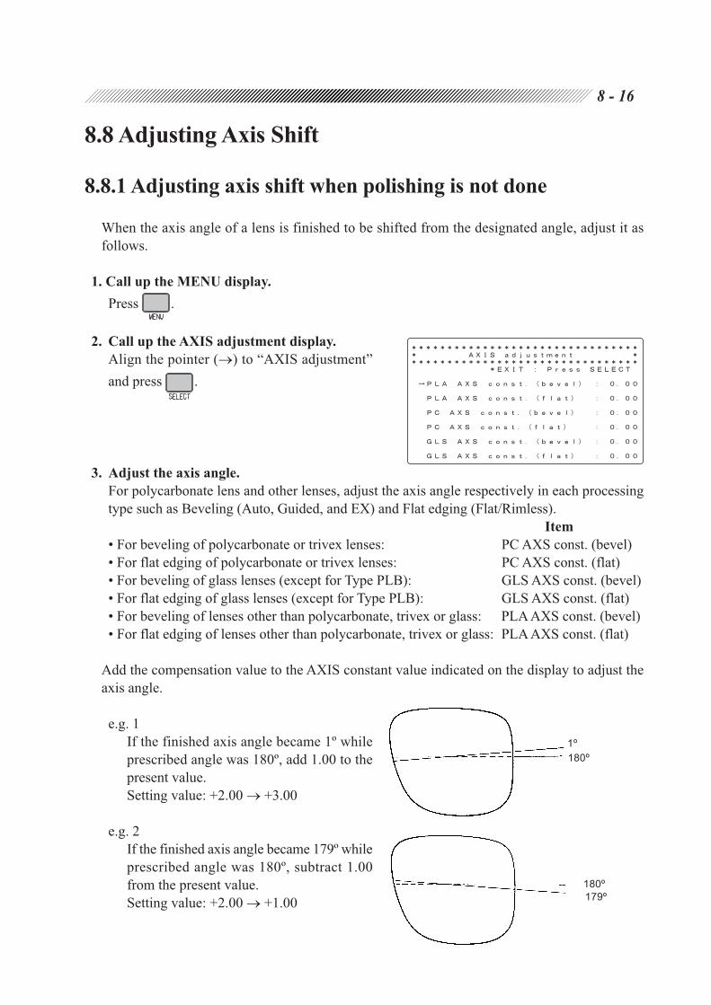
8 - 16
8.8 Adjusting Axis Shift
8.8.1 Adjusting axis shift when polishing is not done
When the axis angle of a lens is finished to be shifted from the designated angle, adjust it as
follows.
1. Call up the MENU display.
Press .
2. Call up the AXIS adjustment display.
Align the pointer ( ) to “AXIS adjustment”
and press .
3. Adjust the axis angle.
For polycarbonate lens and other lenses, adjust the axis angle respectively in each processing
type such as Beveling (Auto, Guided, and EX) and Flat edging (Flat/Rimless).
Item
• For beveling of polycarbonate or trivex lenses: PC AXS const. (bevel)
• For flat edging of polycarbonate or trivex lenses: PC AXS const. (flat)
• For beveling of glass lenses (except for Type PLB): GLS AXS const. (bevel)
• For flat edging of glass lenses (except for Type PLB): GLS AXS const. (flat)
• For beveling of lenses other than polycarbonate, trivex or glass: PLA AXS const. (bevel)
• For flat edging of lenses other than polycarbonate, trivex or glass: PLA AXS const. (flat)
Add the compensation value to the AXIS constant value indicated on the display to adjust the
axis angle.
e.g. 1
If the finished axis angle became 1º while
prescribed angle was 180º, add 1.00 to the
present value.
Setting value: +2.00 +3.00
e.g. 2
If the finished axis angle became 179º while
prescribed angle was 180º, subtract 1.00
from the present value.
Setting value: +2.00 +1.00
180º
179º
1º
180º

8 - 17
4. Go back to the MENU display.
Press .
5. Go back to the Layout display.
Press twice.
6. Repeat Steps 1 - 5 until the correct axis angle is obtained.

8 - 18
8.9 Adjusting Lens Margin Allowed for Finishing
The lens margin is compensated by the following procedure.
1. Call up the MENU display.
Press .
2. Call up the Size adjustment display.
Align the pointer ( ) to “Size adjustment” and
press .
3. Adjust the lens margin.
1) Align the pointer ( ) to the desired item
with .
To adjust the beveled lens margin, specify as follows:
For plastic or acrylic resin lenses, select “Rough size (PLA, bevel)”.
For polycarbonate or trivex lenses, select “Rough size (PC, bevel)”.
For glass lenses, select “Rough size (GLS, bevel)” (except for Type PLB).
For high index plastic lenses, select “Rough size (HPL, bevel)”.
To adjust the flat edged lens margin (including grooved lens), specify as follows:
For plastic or acrylic resin lenses, select “Rough size (PLA, flat)”.
For polycarbonate or trivex lenses, select “Rough size (PC, flat)”.
For glass lenses, select “Rough size (GLS, flat)” (except for Type PLB).
For high index plastic lenses, select “Rough size (HPL, flat)”.
2) Input the compensation value with or .
Adding the value will increase the lens margin allowed for finishing.

8 - 19
4. Go back to the MENU display.
Press .
5. Go back to the Layout display.
Press twice.
8.10 PD Adjustment
If the PD value inputted on the layout display does not agree with the PD of the finished lens,
adjust the PD amount of the finished lens by the following procedure.
1. Call up the MENU display.
Press .
2. Call up the PD adjustment display.
Align the pointer ( ) to “PD adjustment” and
press .
3. Adjust the PD.
Input the compensation value with or .
Adding the value will increase the finished PD.
eg.
When the finished PD becomes 65.5 by inputting PD: 66.0, add 0.50 to the present value.
4. Go back to the MENU display.
Press .
5. Go back to the Layout display.
Press twice.

8 - 20
8.11 Adjustment for Polishing
8.11.1 If a part of edge is left unpolished (Type PL4, PLB, and PLB-2R)
1. Call up the MENU display.
Press .
2. Call up the Size adjustment display.
Align the pointer ( ) to “Size adjustment” and
press .
3. Adjust the amount by which a lens is pressed
against the wheel.
1) Align the pointer ( ) to the item with .
For polishing beveled edge of plastic, high index plastic, or acrylic resin lenses:
“Polish level (PLA, bevel)”
For polishing flat edge of plastic, high index plastic, or acrylic resin lenses:
“Polish level (PLA, flat)”
For polishing beveled edge of polycarbonate or trivex lenses:
“Polish level (PC, bevel)”
For polishing flat edge of polycarbonate or trivex lenses:
“Polish level (PC, flat)”
2) Input the compensation value with or .
If the value increases, the pressed amount against the wheel also increases.
NOTE
• If a large amount is added at once, the polished edge may become rough. Increase the
amount by 0.1 mm increments and check the polished edge each time the base value is
changed.
Besides, never increase the constant value to 0.5 mm or more.

8 - 21
4. Go back to the MENU display.
Press .
5. Go back to the Layout display.
Press twice.
6. Repeat Steps 1 - 5 until the whole edge is polished evenly.*1
7. Check the finished size after polishing.
Check each material lens for beveling and flat edging (only flat edging of Type PL4).
1) Call up the 45 internal data.
Press while pressing on the Layout display.
2) Polish the beveled lens or flat edged lens.
Leave the Size indication 0.
3) Check the finished size.
If the edged lens diameter is as follows, it is
proper.
Beveled lens: 45.00 - 45.10 mm (dia.)
Flat edged lens: 45.00 - 45.10 mm (dia.)
8. If the finished lens size is too large or too small, adjust the polishing size.
1) Call up the MENU display.
Press .
2) Call up the Size adjustment display.
Align the pointer ( ) to “Size adjustment”
and press .
*1 If the lens edge is not polished completely even though the constant value was adjusted, the
axis angle may be shifted, while the edge is being polished. In such a case, input the
compensation value indicated at “POL AXS const. (bevel)” or “POL AXS const. (flat)” as
described in “8.11.3 Axis shift adjustment for polishing” (p. 8-24).

8 - 22
3) Align the pointer ( ) to the desired item with .
To adjust the beveled lens margin, specify as follows:
For plastic or acrylic resin lenses, select “Polish size (PLA, bevel)”.
For polycarbonate or trivex lenses, select “Polish size (PC, bevel)”.
For high index plastic lenses, select “Rough size (HPL, bevel)”.
To adjust the flat edged lens margin (including grooved lens), specify as follows:
For plastic or acrylic resin lenses, select “Polish size (PLA, flat)”.
For polycarbonate or trivex lenses, select “Polish size (PC, flat)”.
For high index plastic lenses, select “Polish size (HPL, flat)”.
4) Input the compensation value with or .
e.g.
If the edged lens diameter became 45.5 mm,
subtract 0.50 from the present value.
Setting value:
0.00 mm 0.50 mm
5) Go back to the MENU display.
Press .
6) Go back to the Layout display.
Press twice.
9. Repeat Steps 7 - 8 until the correct lens size is obtained.

8 - 23
8.11.2 If the front edge or rear edge is left unpolished
(Type PLB and PLB-2R)
The polished bevel position is adjusted by the following procedure.
1. Call up the MENU display.
Press .
2. Call up the Size adjustment display.
Align the pointer ( ) to “Bevel adjustment”
and press .
3. Adjust the polished bevel position.
1) Align the pointer ( ) to “Polish bevel
const.”.
2) Input the compensation value.
If the beveled edge on the lens front side is
left unpolished:
Press .
If the beveled edge on the lens rear side is
left unpolished:
Press .
4. Go back to the MENU display.
Press .
5. Go back to the Layout display.
Press twice.
6. Repeat Steps 1 - 5 until both sides of the edge are polished properly.

8 - 24
8.11.3 Axis shift adjustment for polishing (Type PL4, PLB, and PLB-2R)
If the lens edge is not polished completely even after adjustment is made with “POL Differential”,
the axis angle may be shifted. Perform the adjustment of the axis angle by the following procedure.
1. Check the state of the polished lens.
Check beveling and flat edging (only flat edging of Type PL4).
1) Call up the 45 internal data.
Press while pressing on the Layout display.
2) Perform beveling or polishing of the flat
edge.
Leave the Size indication 0.
3) Check the state of the polished lens.
If the lens edge is not polished completely,
perform the adjustment as follows.
2. Call up the MENU display.
Press .
3. Call up the AXIS adjustment display.
Align the pointer ( ) to “AXIS adjustment”
and press .
4. Adjust the axis angle.
Adjust the axis value for the beveling and flat edging.
Item
• For beveling: POL AXS const. (bevel)
• For flat edging: POL AXS const. (flat)
Add the compensation value to the AXIS constant value indicated on the display to adjust
the axis angle.

8 - 25
e.g.
At the sight from the front of lens, the upper
left side is not polished, add 0.50 to the
present value.
Setting value: +1.00 +1.50
e.g.
At the sight from the front of lens, the upper
right side is not polished, subtract 0.50 from
the present value.
Setting value: +1.00 +0.50
5. Go back to the MENU display.
Press .
6. Go back to the Layout display.
Press twice.
7. Repeat Steps 1 - 6 until the whole lens edge is polished.

8 - 26
8.12 Adjustment for Grooving
8.12.1 Setting of initial value for depth and width
1. Call up the MENU display.
Press .
2. Call up the Groove & SFB adjustment
display.
Align the pointer ( ) to “Groove & SFB
adjustment” and press .
3. Align the pointer ( ) to the desired item with
.
Groove Depth: . mm
Factory setting: 0.3 [mm]
Setting range: 0.0 - 0.8 [mm]
Groove Width: . mm
Factory setting: 0.6 [mm]
Setting range: 0.6 - 1.2 [mm]
4. Change the initial value with or .
5. Go back to the MENU display.
Press .
6. Go back to the Layout display.
Press twice.

8 - 27
8.12.2 Adjusting groove position
When the groove of a lens is finished to be displaced from the designated position, adjust the groove
position by changing the groove constant.
1. Check the groove position.
1) Perform grooving with G CRV: 5 : 5 and
PNT: 0.0.
2) Check if the point of the groove is at the
middle of the edge.
If the groove is leaning to either side, adjust
it by the following procedure.
2. Call up the MENU display.
Press .
3. Call up the Groove & SFB adjustment
display.
Align the pointer ( ) to “Groove & SFB
adjustment” and press .
4. Align the pointer ( ) to “Groove Position”.

8 - 28
5. Input the compensation value of the groove
position.
To shift the groove toward the front side of the
lens, press .
To shift toward the rear side, press .
The arrow shows that the groove is moved
toward the front side, and shows that it is
moved toward the rear side.
6. Go back to the MENU display.
Press .
7. Go back to the Layout display.
Press twice.
8. Repeat Steps 1 - 7 until the groove position comes at the right position.
8.12.3 Adjusting groove depth
8.12.3.1 Groove depth is not made as designated
Groove depth must be even in circumference. However, if the grooving is not made in the
designated depth, adjust it by changing the constant value of the grooving wheel position.
1. Call up the MENU display.
Press .
2. Call up the Groove & SFB adjustment
display.
Align the pointer ( ) to “Groove & SFB
adjustment” and press .
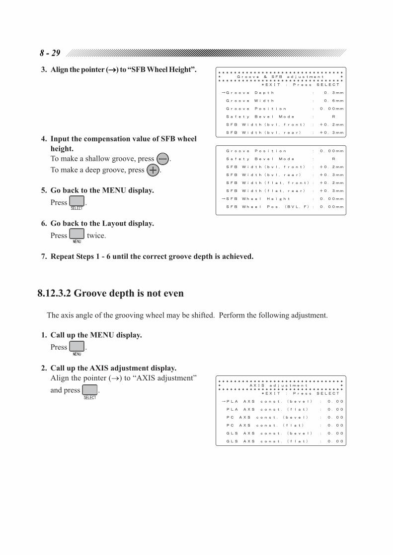
8 - 29
3. Align the pointer ( ) to “SFB Wheel Height”.
4. Input the compensation value of SFB wheel
height.
To make a shallow groove, press .
To make a deep groove, press .
5. Go back to the MENU display.
Press .
6. Go back to the Layout display.
Press twice.
7. Repeat Steps 1 - 6 until the correct groove depth is achieved.
8.12.3.2 Groove depth is not even
The axis angle of the grooving wheel may be shifted. Perform the following adjustment.
1. Call up the MENU display.
Press .
2. Call up the AXIS adjustment display.
Align the pointer ( ) to “AXIS adjustment”
and press .
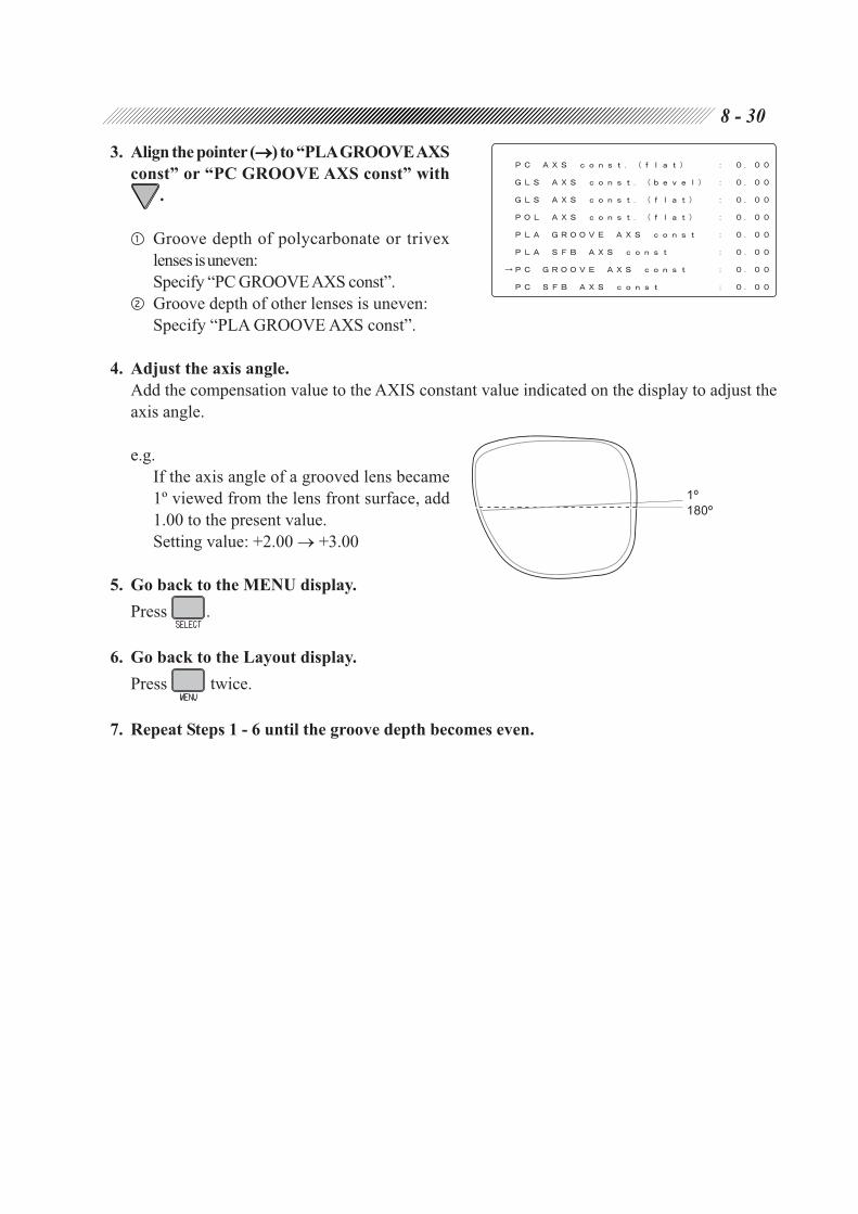
8 - 30
3. Align the pointer ( ) to “PLA GROOVE AXS
const” or “PC GROOVE AXS const” with
.
Groove depth of polycarbonate or trivex
lensesis uneven:
Specify “PC GROOVE AXS const”.
Groove depth of other lenses is uneven:
Specify “PLA GROOVE AXS const”.
4. Adjust the axis angle.
Add the compensation value to the AXIS constant value indicated on the display to adjust the
axis angle.
e.g.
If the axis angle of a grooved lens became
1º viewed from the lens front surface, add
1.00 to the present value.
Setting value: +2.00 +3.00
5. Go back to the MENU display.
Press .
6. Go back to the Layout display.
Press twice.
7. Repeat Steps 1 - 6 until the groove depth becomes even.
1º
180º

8 - 31
8.13 Adjustment for Chamfering
8.13.1 Setting of SFB mode and chamfering amount
1. Call up the MENU display.
Press .
2. Call up the Groove & SFB adjustment
display.
Align the pointer ( ) to “Groove & SFB
adjustment” and press .
3. Align the pointer ) to the desired item with
.
Safety Bevel Mode: F & R, R
Factory setting: R
F & R:
Chamfering of both edges
R:
Chamfering of the rear edge in beveling.
Chamfering of the both edges in flat edging.
SFB Width (bvl, front): . mm
Factory setting: +0.2 [mm]
This is a guide setting for the chamfering
amount of the front SFB in beveling.
SFB Width (bvl, rear): . mm
Factory setting: +0.3 [mm]
This is a guide setting for the chamfering
amount of the rear SFB in beveling.
SFB Width (flat, front): . mm
Factory setting: +0.2 [mm]
This is a guide setting for the chamfering
amount of the front SFB in flat edging.
Front SFB amount Rear SFB amount
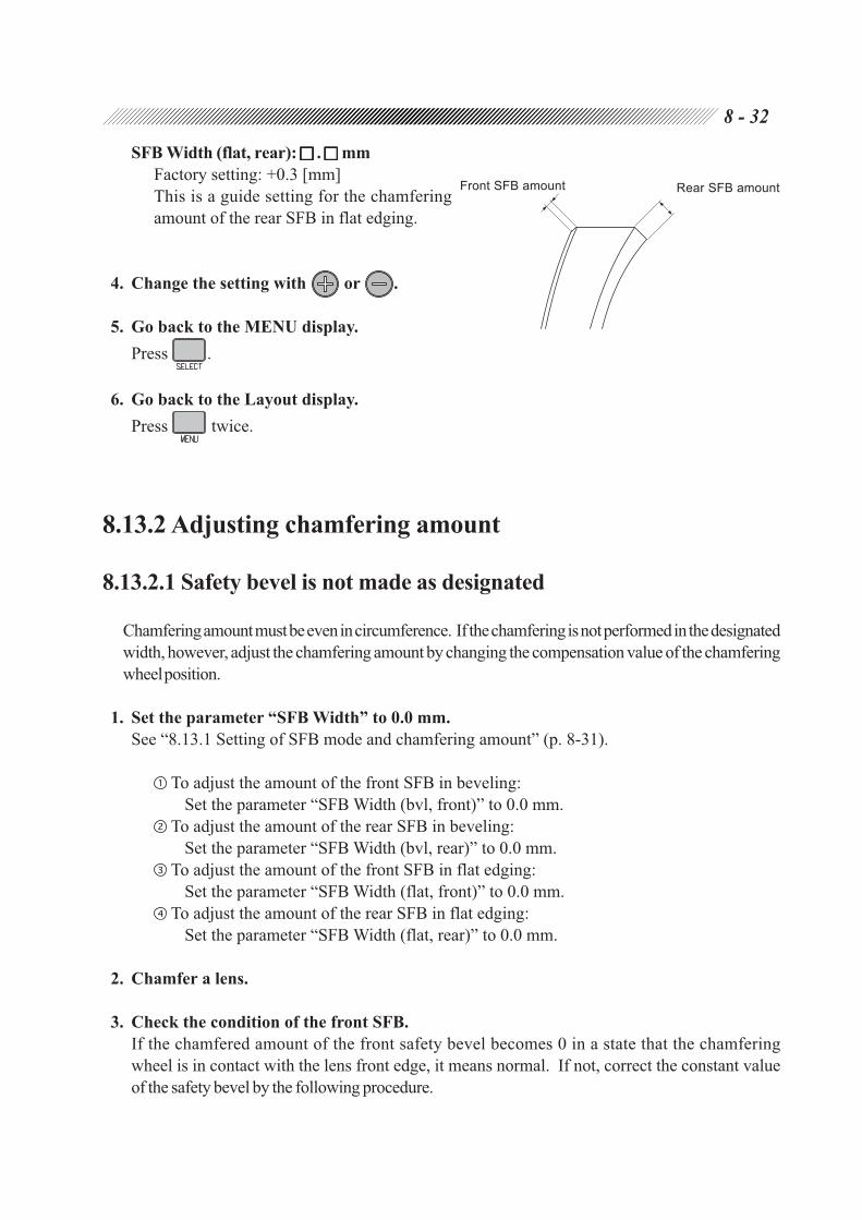
8 - 32
SFB Width (flat, rear): . mm
Factory setting: +0.3 [mm]
This is a guide setting for the chamfering
amount of the rear SFB in flat edging.
4. Change the setting with or .
5. Go back to the MENU display.
Press .
6. Go back to the Layout display.
Press twice.
8.13.2 Adjusting chamfering amount
8.13.2.1 Safety bevel is not made as designated
Chamfering amount must be even in circumference. If the chamfering is not performed in the designated
width, however, adjust the chamfering amount by changing the compensation value of the chamfering
wheel position.
1. Set the parameter “SFB Width” to 0.0 mm.
See “8.13.1 Setting of SFB mode and chamfering amount” (p. 8-31).
To adjust the amount of the front SFB in beveling:
Set the parameter “SFB Width (bvl, front)” to 0.0 mm.
To adjust the amount of the rear SFB in beveling:
Set the parameter “SFB Width (bvl, rear)” to 0.0 mm.
To adjust the amount of the front SFB in flat edging:
Set the parameter “SFB Width (flat, front)” to 0.0 mm.
To adjust the amount of the rear SFB in flat edging:
Set the parameter “SFB Width (flat, rear)” to 0.0 mm.
2. Chamfer a lens.
3. Check the condition of the front SFB.
If the chamfered amount of the front safety bevel becomes 0 in a state that the chamfering
wheel is in contact with the lens front edge, it means normal. If not, correct the constant value
of the safety bevel by the following procedure.
Front SFB amount Rear SFB amount

8 - 33
4. Input the compensation value of SFB wheel position on the Groove & SFB adjustment display.
1) Call up the MENU display.
2) Align the pointer ( ) to “Groove & SFB adjustment” and press .
3) Align the pointer ( ) to the desired item.
To adjust the front SFB in beveling:
Set the parameter “SFB Wheel Pos. (BVL, F)” to 0.0 mm.
To adjust the rear SFB in beveling:
Set the parameter “SFB Wheel Pos. (BVL, R)” to 0.0 mm.
To adjust the front SFB in flat edging:
Set the parameter “SFB Wheel Pos. (FLT, F)” to 0.0 mm.
To adjust the rear SFB in flat edging:
Set the parameter “SFB Wheel Pos. (FLT, R)” to 0.0 mm.
4) Input the compensation value of SFB wheel
position.
To decrease the SFB amount (move the
wheel away from the lens), press .
To increase the SFB amount (move the
wheel toward the lens), press .
5. Go back to the MENU display.
Press .
6. Go back to the Layout display.
Press twice.
7. Repeat Steps 1 - 6 until the chamfering wheel contacts with the front lens edge and the
front SFB becomes 0.

8 - 34
8.13.2.2 Chamfering amount is not even
If the chamfering amount is not even in circumference, the chamfering axis angle may be shifted. Make
the adjustment of the chamfering axis angle.
1. Call up the MENU display.
Press .
2. Call up the AXIS adjustment display.
Align the pointer ( ) to “AXIS adjustment”
and press .
3. Align the pointer ( ) to “PLA SFB AXS
const” or “PC SFB AXS const” with .
Chamfering amount of polycarbonate or
trivex lenses is uneven:
Specify “PC SFB AXS const”.
Chamfering amount of other lenses is
uneven:
Specify “PLA SFB AXS const”.
4. Adjust the axis angle.
Add the compensation value to the AXIS constant value indicated on the display to adjust the
axis angle.
e.g. 1
If the axis angle of a chamfered lens became
1º viewed from the lens front surface, add
1.00 to the present value.
Setting value: +2.00 +3.00
e.g. 2
If the axis angle of a chamfered lens became
1º viewed from the lens rear surface, subtract
1.00 from the present value.
Setting value: +2.00 +1.00
5. Go back to the MENU display.
Press .
1º
180º

8 - 35
6. Go back to the Layout display.
Press twice.
7. Repeat Steps 1 - 6 until the chamfering amount becomes even.
8.14 Tracer Calibration
Perform calibration of the tracer using the provided standard frames or standard pattern. It is
recommended to perform calibration at the time of start to ensure the accuracy of tracing. If an
error occurs in circumference, also perform calibration.
1. Perform calibration with the standard frames.
1) Set the provided standard frames ( 45) into
the tracer.
Set the standard frames, with the side
inscribed with the number face up, fitting
the rim clips into the grooves of the frames.
2) Press while holding down.
The LED beside will blink.
3) Press .
Calibration will be performed.
Calibration is completed after a few tracings. After the electronic beeper sounds, the tracer
exits from the calibration mode and the standard frames are released.
NOTE
• To avoid calibration with frames other than the standard frames, if the circumference
exceeds the correction value of ±1 mm, the LED beside will blink and calibration
will not be performed automatically. In such a case, take the following action.
When the supplied standard frames ( 45) are used, press .
Calibration will be enabled. Go to Step 4).
When other frames are used, press or .
Calibration will be disabled. Perform calibration again with the standard
frames.
4) After calibration is completed, trace the standard frames.
5) Press .

8 - 36
6) Check traced data (circumference) on the
MENU display.
Circumference:
If it is not in the range of 162.83±0.05,
perform calibration with the standard frames
again.
7) Remove the standard frames.
2. Perform calibration with the standard pattern.
1) Set the provided standard pattern into the
tracer.
Fit the standard pattern with the side
inscribed with “A” facing to the pattern
setting unit.
2) Press while holding down.
The LED beside will blink.
3) Press .
Calibration will be performed.
4) After calibration is completed, trace the standard pattern.
5) Press .
6) Check traced data (circumference) on the MENU display.
Circumference:
If it is not in the range of 162.83±0.10, perform calibration with the standard pattern again.
7) Remove the standard pattern.
8.15 List of Consumable ArticlesArticles Order No.
Dressing stick for roughing wheel 41002-M612
Dressing stick for finishing wheel 41002-M611
Dressing stick for polishing wheel 40140-M610
Stocking filter 40377-M061
Fuse (115 Vac) 804-02-02149
Fuse (230 Vac) 804-02-02152
Circumference

Processing system
Beveling Auto: Computer-calculated bevel
Guided: Manual bevel setting, which enables you to select either
the curve profiling the front surface, the curve profiling
the rear surface, the specified curve value, the position
ratio or tilting amount
EX
Flat (Rimless) edging Flat edging
EX
Grooving Auto: Computer-calculated groove position and curve
Guided: Manual-inputted groove position and curve
EX
Polishing
Chamfering
Processing lens
Glass, plastic, high index plastic, polycarbonate, acrylic resin, trivex (except for glass lenses of Type
PLB)
Processing range
Max. Lens size: 90 mm or less in diameter
Layout range: 110 mm or less in diameter
Min. (without safety bevel) In flat edging: 28 mm or more in diameter
(when replaced with the lens adapter and lens clamp
for half-eye lens, up to min. 21 mm dia., vertical
width: 19 mm)(when the optional pliable cup is used,
up to min. 32 mm dia., vertical width: 19 mm)
In beveling: 30 mm or more in diameter
(when replaced with the lens adapter and lens clamp
for half-eye lens, up to min. 22 mm dia., vertical
width: 20 mm)(when the optional pliable cup is used,
up to min. 33 mm dia., vertical width: 20 mm)
Min. (with safety bevel) In flat edging: 34 mm or more in diameter
(when replaced with the lens adapter and lens clamp
for half-eye lens, up to min. 28 mm dia., vertical
width: 25 mm)(when the optional pliable cup is used,
up to min. 32 mm dia., vertical width: 25 mm)
In beveling: 36 mm or more in diameter
(when replaced with the lens adapter and lens clamp
for half-eye lens, up to min. 29 mm dia., vertical
width: 26 mm)(when the optional pliable cup is used,
up to min. 34 mm dia., vertical width: 26 mm)
* The processing range may change according to the processing mode.
§9SPECIFICATIONS

9 - 2
Adjustable range
FPD: 30.0 - 99.5 mm (0.5 mm increments)
PD: 30.0 - 99.5 mm (0.5 mm increments)
1/2 PD: 15.0 - 49.75 mm (0.25 mm increments)
Vertical layout: ±15.0 mm (0.1 mm increments)
Size adjustment: ±9.95 mm (0.05 mm increments)
Bevel position: ±15.0 mm (0.1 mm increments)
Groove position: ±15.0 mm (0.1 increments)
Processing pressure
Approx. 4.5 kg (fixed)
Wheels
Type PC
Roughing wheel for plastic lens: 100 mm in diameter, 22 mm in width
Roughing wheel for glass lens: 100 mm in diameter, 17 mm in width
Finishing wheel: 100 mm in diameter, 23 mm in width
Type PL4
Roughing wheel for plastic lens: 100 mm in diameter, 17 mm in width
Roughing wheel for glass lens: 100 mm in diameter, 17 mm in width
Finishing wheel: 100 mm in diameter, 23 mm in width
Polishing wheel (for flat edge): 100 mm in diameter, 12 mm in width
Type PLB
Roughing wheel for plastic lens: 100 mm in diameter, 22 mm in width
Finishing wheel: 100 mm in diameter, 17.5 mm in width
Polishing wheel (for flat edge and bevel):100 mm in diameter, 17.5 mm in width
Type PLB-2R
Roughing wheel for plastic lens: 100 mm in diameter, 17 mm in width
Roughing wheel for glass lens: 100 mm in diameter, 17 mm in width
Finishing wheel: 100 mm in diameter, 17.5 mm in width
Polishing wheel (for flat edge and bevel):100 mm in diameter, 17.5 mm in width
* Processing lens material and polishing for each wheel component
Type Lens material Polishing
PC PLA/HPL/PC/GLS/ACR/TRX Unavailable
PL4 PLA/HPL/PC/GLS/ACR/TRX Flat edging except for glass lens
PLB PLA/HPL/PC/ACR/TRX Beveling and flat edging except for glass lens
PLB-2R PLA/HPL/PC/GLS/ACR/TRX Beveling and flat edging except for glass lens

9 - 3
Lens chucking
Chucking method: Electric system
Chucking pressure: 20 kgf (pre-operation)
30 - 60 kgf (during operation)
Automatic setting according to lens material
Water supply system
Pump circulation
Other functions
Layout: Active, passive, bifocal
Layout input item: FPD (DBL)
PD (1/2 PD)
Vertical layout
* Eye point layout function is available.
Retouching function: Available (Memory function is available.)
Frame memory function: Standard storable data 100 sets
* The optional barcord scanner allows up to 500 sets of data to
be stored.
External communication: RS-232C 2 ports built-in
function For connecting a PC
For connecting a barcode scanner
Control outlet: 2 pcs. for pumps
Processing accuracy
Beveling size accuracy: ±0.1 mm (dia.)
error in beveling (AUT) of 45 internal data
Flat edging size accuracy: ±0.1 mm (dia.)
error in flat edging (NYL) of 45 internal data
Axis angle: ±1º
Specifications of tracing unit
Tracing method: 3-D binocular automatic tracing
Traceable size: Frame R9 - R46
(vertically up to max. 30 mm from center)
Pattern R12 - R46
(vertically up to min. 10 mm from center)
FPD measurement function: Available
Frame clamp: One-touching automatic clamp
Framing of stylus: Switchable between automatic and semiautomatic

9 - 4
Measurement accuracy: Frame tracing ±0.05 mm
(circumference error with 45 standard frame)
Pattern tracing ±0.1 mm
(circumference error with 45 standard pattern)
Measurement time: 30 seconds (at binocular automatic tracing)
20 seconds (at pattern tracing)
Whole system
Dimensions: 520 (W) × 484 (D) × 330 (H) mm (only main body)
Weight: 42 kg (only main body)
Power supply: A. AC115 V 50/60 Hz
B. AC230 V 50/60 Hz
(Main supply voltage fluctuation should not exceed ±10% of the
nominal voltage.)
* Each setting of A and B is set in factory.
Power consumption: 1.2 k VA (max. during processing)
Acoustic noise: Maximum 70 dB (A)
according to Clause 1.7.4 of Machinery Directive
Environmental condition (during transport/storage)
Temperature: –25ºC - 70ºC
Humidity: 10% - 100%
Pressure : 700 hPa - 1060 hPa
(The conditions above indicate the state of the instrument packed.)
Environmental condition (during use)
Setting location: Indoor
Temperature: 5ºC - 40ºC
Humidity: Relative humidity does not exceed 50% at a maximum temperature
of 40ºC.
Pressure: 700 hPa - 1060 hPa
Altitude: Up to 1000 m at sea level
Transient overvoltages according to installation categories
(OVERVOLTAGE CATEGORIES)
II
Pollution degree 2 (IEC60664)

10.1 NIDEK-type Accessories
Operator’s manual ................................................................................... 1 pc.
Suction cup .............................................................................................. 3 pcs.
Lens cup .................................................................................................. 5 pcs.
Double-coated adhesive tape ................................................................... 1 sheet
Dressing stick for roughing wheel (WA80K) ............................................. 1 pc. (except for PLB)
Dressing stick for finishing wheel (WA320K) ............................................ 1 pc.
Dressing stick for polishing wheel (WA4000) ....................................... 1 pc. (except for PC)
Half-eye lens cup (blue) ......................................................................... 5 pcs.
Half-eye lens cup (white) ....................................................................... 5 pcs.
Half-eye lens cup (pink) ......................................................................... 5 pcs.
Half-eye adapter ..................................................................................... 1 pc.
Half-eye lens clamp ................................................................................ 1 pc.
Double-coated adhesive tape for half-eye lens ....................................... 1 sheet
Lens cup remover ................................................................................... 1 pc.
Pattern setting unit .................................................................................. 1 pc.
Calibration jig ........................................................................................ 1 pc.
Standard frame ....................................................................................... 1 pc.
Standard pattern ...................................................................................... 1 pc.
Spare fuse ............................................................................................... 2 pcs.
Power cord ............................................................................................. 1 pc.
Hex driver .............................................................................................. 1 pc.
Hex wrench (3 mm) ................................................................................ 1 pc.
Hex wrench (4 mm) ................................................................................ 1 pc.
10.2 WECO-type Accessories
Operator’s manual .................................................................................. 1 pc.
Double-coated adhesive tape ................................................................. 1 sheet
Dressing stick for roughing wheel (WA80K) ........................................ 1 pc. (except for PLB)
Dressing stick for finishing wheel (WA320K) ...................................... 1 pc.
Dressing stick for polishing wheel (WA4000) ....................................... 1 pc. (except for PC)
Half-eye adapter ..................................................................................... 1 pc.
Half-eye lens clamp ............................................................................... 1 pc.
Pattern setting unit ................................................................................. 1 pc.
Calibration jig ........................................................................................ 1 pc.
Standard frame ....................................................................................... 1 pc.
Standard pattern ..................................................................................... 1 pc.
Spare fuse ............................................................................................... 2 pcs.
Power cord ............................................................................................. 1 pc.
Hex driver .............................................................................................. 1 pc.
Hex wrench (3 mm) ................................................................................ 1 pc.
Hex wrench (4 mm) ................................................................................ 1 pc.
§10ACCESSORIES

10 - 2
10.3 SANTI-type Accessories
Operator’s manual .................................................................................. 1 pc.
Double-coated adhesive tape ................................................................. 1 sheet
Dressing stick for roughing wheel (WA80K) ........................................ 1 pc. (except for PLB)
Dressing stick for finishing wheel (WA320K) ...................................... 1 pc.
Dressing stick for polishing wheel (WA4000) ....................................... 1 pc. (except for PC)
Half-eye lens clamp ............................................................................... 1 pc.
Pattern setting unit ................................................................................. 1 pc.
Calibration jig ........................................................................................ 1 pc.
Standard frame ....................................................................................... 1 pc.
Standard pattern ..................................................................................... 1 pc.
Spare fuse ............................................................................................... 2 pcs.
Power cord ............................................................................................. 1 pc.
Hex driver .............................................................................................. 1 pc.
Hex wrench (3 mm) ............................................................................... 1 pc.
Hex wrench (4 mm) ............................................................................... 1 pc.

Tracing one rim only
Tracing single rim
Set frames into the tracing unit.
Press or .
See "4.3.1.2 Tracing single rim" (p. 4-
5).
A.1 Selection of Tracing
(1) Tracing frames
Normal tracing
Tracing both rims
Set frames into the tracing unit.
Press .
See "4.3.1.1 Tracing both rims" (p. 4-
4).
Semiauto tracing
Set frames into the tracing unit.
Press for 3 seconds.
Set the stylus into the bevel groove
with fingers.
Press
See "4.3.1.3 Semiauto tracing" (p. 4-
5).
When the stylus does not get into
the bevel groove automatically
Tracing goggle type frames
Set one rim horizontally to the tracing
unit.
Tracing single rim.
See "4.3.1.4 Tracing goggle type
frames" (p. 4-6).
Tracing sharply warped frames
APPENDIX A SUPPLEMENT

A - 2
Tracing pattern
Pattern tracing
Set a pattern to the tracing unit.
Press or .
See "4.3.2 Tracing pattern" (p. 4-7).
(2) Tracing pattern or dummy lens
(3) Other functions
Tracing during processing
See "4.3.4 Tracing during processing"
(p. 4-10).
Tracing dummy lens
Dummy lens tracing
Set a dummy lens to the tracing unit.
Press or .
See "4.3.3 Tracing dummy lens."
(p. 4-8).
Stopping tracing
See "4.3.5 Stopping tracing" (p. 4-10).

A - 3
Inputting eyepoint
See "4.4.3 Eye point layout" (p. 4-17).
This is a form to input the eyepoint as
the optical center by the distance
measured from the nasal and bottom
sides of the lens outline.
Inputting height from lens outline
See "4.4.2 Inputting height from lens
outline (p. 4-14).
This is a form to input the height of
optical center by measuring the
distance from eye point to the bottom
of the lens outline.
Inputting monocular PD (1/2PD)
See *5 of p. 4-13.
This is a form to input the distance
from the frame bridge center to each
eye point separately.
DBL input
See *4 of p. 4-12.
This is a form to input DBL (distance
between nasal ends of right and left
rims) instead of FPD.
Normal input
See "4.4.1 Selecting processing
conditions and inputting layout data"
(p. 4-11).
This is a form to input FPD, PD and
the height of optical center from the
center of the rim ( ).
A.2 Selection of Layout
(1) Layout forms
FPD
PDPD
1/2PD 1/2PDOptical center Optical center
PDBT
Optical center← →← →← →← →← →
PD
DBL Optical center
PD

A - 4
Bifocal mode
See "4.5.3 Blocking bifocal lens"
(p. 4-20).
This is for bifocal lens. Block at 5 mm
up and 5 mm outside position from the
top line center of segment with a lens
cup.
Active mode
See "4.5.1 Blocking in active mode
(p. 4-18).
This is for blocking a lens at the
optical center.
A.3 Selection of Blocking
FPDFPD
PDPD
Hor i zon ta l l yd e c e n t e r i n gamount
Blocking point Optical center Rim center
Blocking point:Rim center
Optical center
Rim center
PD for near vision5mm OUTSIDE
PD BT
5mm UP
Blocking point: 5 mm U/ 5 mm OUTSIDE
(2) Selection of lens and layout
Bifocal lens
See "4.4.2.1 Layout of bifocal lens"
(p. 4-15).
Progressive power lens
See "4.4.2.2 Layout of progressive
power lens" (p. 4-16).
V e r t i c a l l yd e c e n t e r i n gamount
Passive mode
See "4.5.2 Blocking in passive mode
(p. 4-19).
This is for blocking a lens at the rim
center.

A - 5
Adjusting bevel position
Adjusting groove position
Select "NYL" and "GUI".
Press .
Check the Groove simulation display.
Adjust the groove curve and groove
position.
Press .
See "4.6.2.4 Guided grooving mode"
(p. 4-43).
Adjusting bevel position
Guided processing mode
Select "GUI".
Press .
Check the Bevel simulation display.
Adjust the bevel curve and bevel
position.
Press .
See "4.6.1.2 Guided processing
mode" (p. 4-25).
A.4 Selection of Processing
(1) Processing mode
EX lens flat edging
See "4.6.2.2 EX lens flat (rimless)
edging mode" (p. 4-39).
See "4.6.1.1 Auto processing mode"
(p. 4-22).
Creating computer-calculated
bevel
See "4.6.1.4 EX lens processing
mode" (p. 4-32).
Creating bevel on EX lens
Flat edging
See "4.6.2.1 Flat (rimless) edging
mode" (p. 4-36).
See "4.6.2.3 Auto grooving mode"
(p. 4-41).
Creating computer-calculated
groove
EX lens grooving mode
See "4.6.2.5 EX lens grooving mode"
(p. 4-47).

A - 6
Processing for frame change
Trace frames.
Press .
Press .
Trace the lens.
Set processing conditions and input
layout data.
Press .
See "4.6.3.1 Processing for frame
changing" (p. 4-50).
Processing a lens which has
already been mounted on one
frame in order to fit it into another
Retouching
Change the size value.
Press .
See "4.7 Checking Lens Size" (p. 4-
60).
Finished lens size is too large for
frame
(2) Special processing
Processing half-eye lens
Half-eye lens processing
The message "Use chuck for half-
eye lens" appears.
Replace the adapter set with the one
for half-eye lens.
See "4.6.3.2 Processing half-eye lens
(p. 4-53).
Polishing lens edge
See "4.6.3.3 Polishing" (p. 4-56).
Chamfering
See "4.6.3.4 Chamfering" (p. 4-57).

The instrument is provided with the self-diagnostic function that monitors operations all the time.
When any failure occurs in the instrument, it will stop automatically and show the error code on the
display panel. In an event of failure, inform the error code as well as the symptoms of the instrument.
The error code is essential to proper repair work.
The contents of each error code are as follows. As for the error code whose action is provided,
follow its procedure before contacting NIDEK or your authorized distributor.
APPENDIX B ERROR CODE
ERROR CODE CONTENTS
0001
Processing error transmission error
Action: Check the cable from the RS232C connector and connections of the
peripheral devices.
0002
Processing error reception error
Action: Check the cable from the RS232C connector and connections of the
peripheral devices.
0104 Output voltage of grinding end sensor is improper.
0201
Feeler Assy. is not initialized.
Action: Press after moving feeler to center of processing chamber by lifting. If feeler
cannot be moved to center in relation to position with lens, turn power off. Then, move
feeler to center after moving shaft
0204
After rear surface of lens is measured, its front surface cannot be
measured.
Action: While front surface is measured, hold feeler down lightly.
0205Data for lens measurement or lens measured result is abnormal.
Aciton: Perform operation again from frame tracing.
0206 First data in lens shape measurement is abnormal.
0207Data of start and end in lens shape measurement does not agree.
Action: Perform operation again from lens shape measurement by pressing .
0208 When rear surface of lens is measured, feeler is positioned beyond its measurable range.
0209 When front surface of lens is measured, feeler is positioned beyond its measurable range.
0301Y axis data for processing is abnormal.
Action: Perform operation again from frame tracing.
0302
X axis data for processing is abnormal.
Action: If error occurs before processing, perform operation again from lens shape
measurement by pressing .
0401 X, Y, or θ axis motor is abnormal.
0402 Initialization of X axis motor is abnormal.
0403 Initialization of Y axis motor is abnormal.
0404 Initialization of θ axis motor is abnormal.
0408
Initialization of F axis motor is abnormal.
Action: Press to clear the error messasge. After moving the feeler to the
center of the processing unit, turn the power off and then on.
0501 Chuck motor does not run.
0601 Chamfering/grooving wheel motor is abnormal. (overcurrent)
0602 Initialization of chamfering/grooving unit is abnormal.
0603 Grinding end sensor error of chamfering/grooving unit.
0604 Setting position of processing end sensor of chamfering/grooving unit is improper.

B - 2
ERROR CODE CONTENTS
0801 CPU false interrupt error.
0802 CPU address error.
0803 CPU DMA bus error.
0900 Error in writing of EEPROM.
0901 Size constant in rough edging is out of its specified range.
0902 Size constant is out of its specified range.
0903 Bevel constant is out of its specified range.
0904 Parameter of wheel position is out of its specified range.
0905 Frame memory verification error.
0906 Frame memory CRC check error.

In this manual, the following terms are used to provide an easy understanding of the contents.
Therefore, thoroughly understand before reading the contents of this manual.
Active mode
This is for blocking a lens at the optical center.
Auto processing mode
In this mode, the bevel curve and bevel position are automatically calculated by the computer for their best
values of processing.
Auto grooving mode
In this mode, the groove curve and groove position are automatically calculated by the computer for their best
values of grooving.
Bifocal mode
This mode is for laying out the bifocal lenses. In this mode, a lens is blocked at 5 mm up and 5 mm outside
from the top line center of segment with a lens cup, with a centering device.
Chamfering
This is a processing method to chamfer a lens edge of the rear surface or both surfaces before the processing is
completed.
DBL (Distance Between Lenses)
This represents the distance between nasal ends of the left and right rims.
EX lens processing mode
This mode serves to process EX lenses. In this mode, the bevel curve follows the rear surface.
EX lens grooving mode
This mode serves to groove EX lenses for nylor frames. In this mode, the groove curve follows the rear
surface.
Eye point layout
This is a form to input the eye points as the optical center by the distance measured from the nasal and bottom
side of lens outline. This form serves to specify the position of the eye point, which is marked on the dummy
lenses, as the optical center.
FPD (Frame Pupillary Distance)
This represents the distance between right and left rim centers.
The rim centers are calculated by boxing system.
Goggle type frame tracing
This is a process to trace a sharply warped frame, such as goggles. The stylus may often come off the groove
of such a frame. In such cases, set only one rim in the tracing unit and hold the frame temple on the other side
while tracing.
APPENDIX C GLOSSARY
DBL
FPD

C - 2
Processing for frame changing mode
This is a process to process a lens, which has already been mounted on one frame, in order to fit it into another
frame.
Guided processing mode
In this mode, the bevel curve and bevel position can be specified manually.
Guided grooving mode
In this mode, the groove curve and groove position for nylor frames can be specified manually.
Half-eye lens processing
For the frame whose vertical diameter is short, the mark of the optical center becomes , and as soon as
processing starts, the “Use chuck for half-eye lens” message will appear and the instrument will stop temporarily.
These indications mean that the lens adapter or lens clamp may contact with the wheels. Replace the lens
adapter, lens clamp and lens cup with the ones for half-eye lens.
Memory function
This is a function which memorizes the traced data and layout data in the memory and read them whenever
necessary. The memory holds up to 100 sets of the traced and layout data at most.
Passive mode
This is for blocking a lens at the rim center.
Polishing
This is a processing method to polish the lens edge to save your time required to buff the lens edge after
beveling or flat edging.
Semiauto tracing
This is a procedure to manually bring the stylus into the groove of the frame in a case that the stylus cannot get
in the groove automatically.
Simple frame changing mode
This is a processing procedure to process a lens in the frame changing mode without tracing the lens. When the
lens size is enough for the new frame and there is no need of lens tracing, trouble for lens tracing can be saved
in this mode.
Single rim tracing
This is a procedure to trace one of the frame rims.
Storage of initial display
This is a function to store the items on the layout display which appears at power-up.
TRX
One of the lens material settings. Used to process lenses that melt easily from heat such as a trivex lens.

A
Active mode .............................................. 4-18
Adjusting axis shift ................................... 8-16
Adjusting bevel position ........................... 8-14
Adjusting groove position ........................ 8-27
Adjusting lens marginallowed for finishing .............................. 8-18
Auto-correction of FPD ............................ 4-37
Auto processing mode .............................. 4-22
Auto grooving mode ................................. 4-41
B
Barcode scanner ................................. 3-2, 5-10
Bevel curve ............................................... 4-26
Beveling .................................................... 4-21
Bevel position ........................................... 4-27
Bevel simulation ..................... 4-25, 4-33, 4-48
Bifocal lens ...................................... 4-15, 4-20
Blocking lenses ......................................... 4-18
C
Cataract lens ........................... 4-12, 4-21, 4-26
Chamfering ............................. 4-12, 4-21, 4-55
Chamfering amount ......................... 8-31, 8-32
Contrast control .......................................... 3-1
Control panel for processing unit ........ 3-1, 3-7
Control panel for tracing unit ..................... 3-5
Cup remover ............................................. 4-62
D
Daily check after use ................................ 4-65
Daily check before use .............................. 4-64
DBL ................................................... 3-9, 4-12
Display panel ....................................... 3-1, 3-9
E
Error code (No.) ....................... 2-10, 3-13, B-1
EX lens ................................... 4-32, 4-39, 4-47
EX lens processing mode ......................... 4-32
EX lens flat (rimless) edging mode .......... 4-39
EX lens grooving mode ............................ 4-47
Ext. interface ............................................... 5-4
Eye point layout ........................................ 4-17
F
Finishing wheel ........................................... 3-4
Flat (rimless) edging mode ....................... 4-36
Flat (rimless) edging ................................. 4-36
FPD ...................................................... 3-9, 5-3
Frame changing mode............................... 4-19
Frame Pupillary Distance ........................... 3-9
Front base curve ............................... 4-26, 4-43
G
Glass soft processing ................................ 4-58
Groove curve ............................................ 4-44
Groove depth ................................... 8-26, 8-28
Groove position ........................................ 4-45
Groove simulation ............................. 3-3, 4-44
Groove width ............................................ 8-26
Guided processing mode .......................... 4-25
Guided grooving mode ............................. 4-43
I
In a case that the stylus cannot be setin the groove automatically ...................... 4-6
Inputting the frame tilt angle .................... 4-59
L
Layout ....................................................... 4-12
Layout display............................................. 3-9
Lens material ....................................... 1-1, 9-2
M
Memory address.......................................... 5-9
Memory function ................................. 5-4, 5-8
MENU display .......................................... 3-13
Minimum lens diameter .............................. 3-9
Monocular PD........................................... 4-13
INDEX

P
Parameter exchange mode display ............ 3-13
Parameter settings ....................................... 5-2
Passive mode ............................................ 4-19
Pattern setting unit ...................................... 4-7
Pattern setting unit support ......................... 4-7
Pattern tracing pin ....................... 3-5, 4-8, 4-10
Periodical check ........................................ 4-66
PD ........................................................ 3-9, 5-3
PD adjustment .......................................... 8-19
PNT........................................................... 4-36
Polishing ................................. 4-12, 4-21, 4-56
Polishing wheel........................................... 3-4
Power switch........................................ 3-1, 4-3
Process counter ........................................... 5-1
Processing conditions ................................4-11
Processing for frame changing ................. 4-50
Processing half-eye lens ........................... 4-53
Processing mode ................................ 3-8, 4-21
Processing type ........................................... 1-1
Progressive power lens .................... 4-16, 4-18
Pupillary distance........................................ 3-9
R
Ratio ................................................ 4-26, 4-45
Rear base curve ................................ 4-26, 4-45
Replacing the water .................................... 8-5
Retouching lens ........................................ 4-60
Rim clips ..................................................... 3-5
Roughing wheel for glass lens .................... 3-4
RS-232C interface connector ...................... 3-2
S
Sectional viewposition line ............... 4-25, 4-33, 4-44, 4-48
Semiauto tracing ......................................... 4-5
SFB mode ................................................. 8-31
Simple frame changing mode ................... 4-52
Simulation display .....................................3-11
Size adjustment ....................... 4-13, 4-60, 8-13
Soundproof cover ....................................... 3-1
Stocking filter ...................................... 8-5, 8-8
Storing initial display .................................. 5-6
Storing and calling up the traced data ......... 5-7
Stylus .......................................................... 3-5
T
Tilt base position .......................................3-11
TILT function (parameter) .......................... 5-5
Tilting function ................................ 4-29, 4-34
Tracer calibration ...................................... 8-35
Tracing both rims ........................................ 4-4
Tracing dummy lens ................................... 4-8
Tracing goggle type frames......................... 4-6
Tracing pattern ............................................ 4-7
Tracing single rim ....................................... 4-5
Tracing unit ................................................. 3-5
Two-point .................................................. 4-36
W
Wheels ........................................................ 3-3
Wheel dressing ........................................... 8-1
Index - 2


