

Rev. 10/3/2011
Product:
Corvette Racing Sway Bars
Part �umbers:
1110212 – Heavy Rate
1110213 – C6 Z06 Heavy Rate
1110292 – Light Rate
Applications:
Chevrolet Corvette, 1997 - Current
Description:
These racing sway bars are engineered to be a lightweight,
adjustable racing sway bar system for C5 and C6 Corvettes.

2
What’s in the box:
Item Qty
Assembled Front Sway Bar 1
Assembled Rear Sway Bar 1
Bag of Bushings and Grease 1
Bag of Hardware 1 Flange Nut (M12x1.75) 4
Flange Nut (3/8-24) 4
Jam Nut, LH 4
Jam Nut, RH 4
Socket Head Cap Screw 4
Spacer 4
Turnbuckle 4
Studded Heim Joint, RH 4
Heim Joint, LH 4
Installation Tool (Front Bar) 1
Installation Tool (Rear Bar) 1
Difficulty of Installation: Beginner |------x--------------------------------------| Advanced
Reason: This product is a very straight forward to install and requires only basic tools.
Expected Installation Time: 2 Hours and 10 Minutes
Recommended Tools:
• 18mm box end wrench
• 15mm open end wrench
• 2 x 9/16 open end wrenches
• 3/4 box end wrench
• 13mm socket and ratchet
• 18mm socket and ratchet
• 6mm Allen
• 5/16 Allen wrench
• 1/4 Allen wrench
• 3/32 Allen wrench
• Torque wrench
3
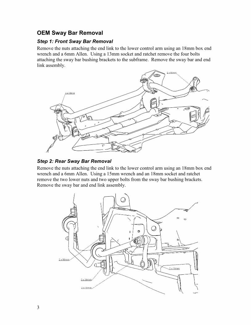
OEM Sway Bar Removal
Step 1: Front Sway Bar Removal
Remove the nuts attaching the end link to the lower control arm using an 18mm box end
wrench and a 6mm Allen. Using a 13mm socket and ratchet remove the four bolts
attaching the sway bar bushing brackets to the subframe. Remove the sway bar and end
link assembly.
Step 2: Rear Sway Bar Removal
Remove the nuts attaching the end link to the lower control arm using an 18mm box end
wrench and a 6mm Allen. Using a 15mm wrench and an 18mm socket and ratchet
remove the two lower nuts and two upper bolts from the sway bar bushing brackets.
Remove the sway bar and end link assembly.

4
Pfadt Sway Bar Installation Procedure
Step 1: Assemble End Links
Assemble each of the four end links as shown below. The end of the turnbuckle with left
hand threads is denoted by the incomplete wrench flats. Adjust two of the end links to
approximately 90 mm for the front sway bar and two of them to approximately 80 mm
for the rear sway bar. It is not necessary to tighten the jam nuts at this time.
Step 2: Install Front End Links
Install one of the 90mm long end link assemblies onto each of the front lower control
arms. Use a 15mm open end wrench on the flats of the heim joint stud to prevent it from
rotating as you tighten the nut using an 18mm socket. Torque to76 N-m (56 ft-lbs).
End Link Length
�OTE: To prevent thread galling, do not use a high-speed driver such as
an impact gun on the flange nut. Only tighten by hand and torque to spec.

5
Step 3: Install Front Sway Bar
Using the supplied grease, grease the inside of the front bushings and the outside of the
sway bar where the bushings will rest. Install the bushings over the sway bar, making
sure the centering rings are on the outside of the bushings during installation.
Using the factory bushing brackets and bolts, install the sway bar onto the subframe.
Torque the mounting bolts to 58 N-m (43 ft-lbs). Test the movement of the sway bar.
You should be able to rotate the bar by hand with moderate force on the ends of the arms.
If it's too tight, place a 1/2" or 12mm washer on the bolts between the brackets and the
frame and repeat the process.
Center the sway bar on the subframe so that the length from the bushing bracket to the
end of the bar is the same on both sides. Slide the centering rings next to the bushings
and lock in place using the provided set screws. Tighten the set screws with a 3/32 Allen
wrench.

6
Attach the sway bar arms to the end links. Place the spacer between the arm and the
end link as shown below and secure with the bolt and nut. The spacer must be properly
installed to allow the heim joint to articulate adequately through full suspension travel
without binding. Torque the bolt to 45 N-m (33 ft-lbs).

7
Step 4: Install Rear End Links
Install one of the 80mm long end link assemblies onto each of the rear lower control
arms. Use a 15mm open end wrench on the flats of the heim joint stud to prevent it from
rotating as you tighten the nut using an 18mm socket. Torque to 76 N-m (56 ft-lbs).
�OTE: To prevent thread galling, do not use a high-speed driver such as
an impact gun on the flange nut. Only tighten by hand and torque to spec.
8
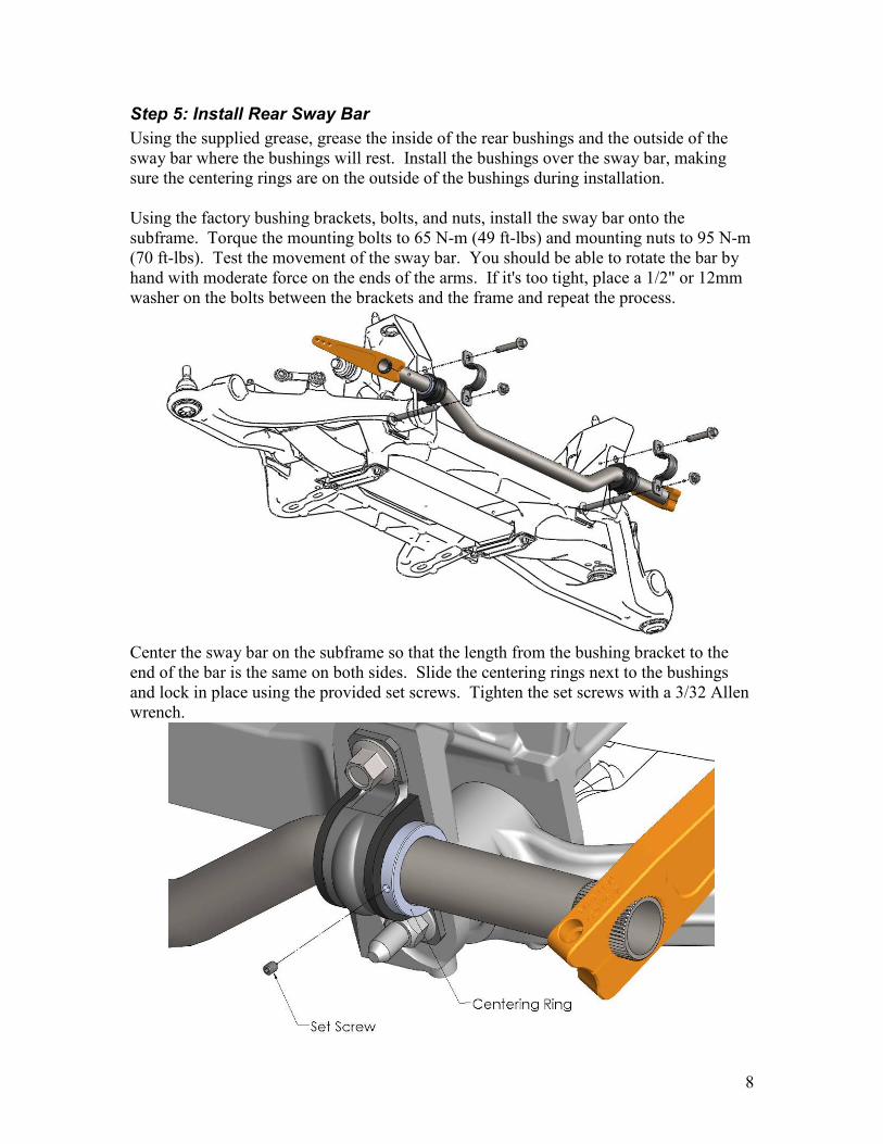
Step 5: Install Rear Sway Bar
Using the supplied grease, grease the inside of the rear bushings and the outside of the
sway bar where the bushings will rest. Install the bushings over the sway bar, making
sure the centering rings are on the outside of the bushings during installation.
Using the factory bushing brackets, bolts, and nuts, install the sway bar onto the
subframe. Torque the mounting bolts to 65 N-m (49 ft-lbs) and mounting nuts to 95 N-m
(70 ft-lbs). Test the movement of the sway bar. You should be able to rotate the bar by
hand with moderate force on the ends of the arms. If it's too tight, place a 1/2" or 12mm
washer on the bolts between the brackets and the frame and repeat the process.
Center the sway bar on the subframe so that the length from the bushing bracket to the
end of the bar is the same on both sides. Slide the centering rings next to the bushings
and lock in place using the provided set screws. Tighten the set screws with a 3/32 Allen
wrench.

9
Attach the sway bar arms to the end links. Place the spacer between the arm and the
end link as shown below and secure with the bolt and nut. The spacer must be properly
installed to allow the heim joint to articulate adequately through full suspension travel
without binding. Torque the bolt to 45 N-m (33 ft-lbs).
10
Initial Setup
For best performance, remove any pre-load in the sway bar while the suspension is
loaded. This is best done on a four post lift, but it is also possible to set the car down on
blocks or ramps so that the end links can be accessed while the suspension is loaded.
Disconnect the end link from the sway bar arm at one end of the sway bar. Adjust the
length of the end link so that the bolt can be slipped through the end link and the hole in
the sway bar arm without having to apply any force to the arm to get the parts to line up
perfectly.
After the end link length is adjusted to remove any preload, lock down the length by
tightening the jam nuts.
For the initial setting of the sway bars we recommend position 2 for both the front and
rear sway bars. For most applications this will be a satisfactory setting and is a good
starting point for all cars.
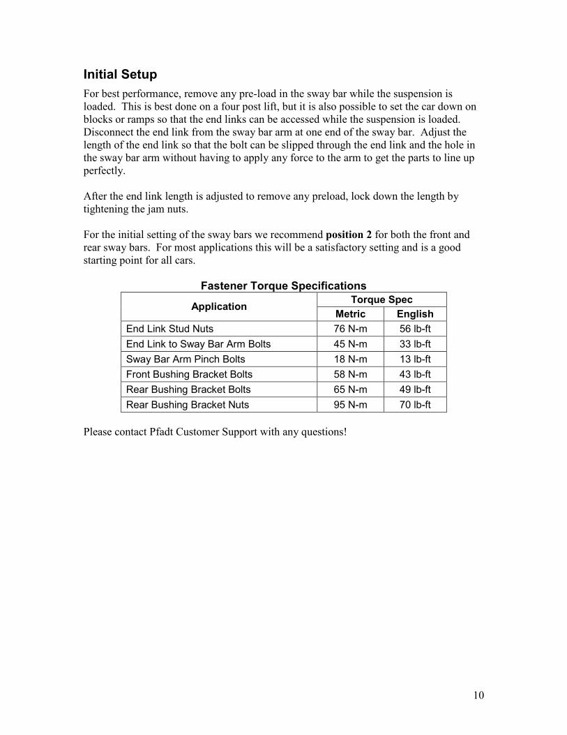
Fastener Torque Specifications
Torque Spec Application
Metric English
End Link Stud Nuts 76 N-m 56 lb-ft
End Link to Sway Bar Arm Bolts 45 N-m 33 lb-ft
Sway Bar Arm Pinch Bolts 18 N-m 13 lb-ft
Front Bushing Bracket Bolts 58 N-m 43 lb-ft
Rear Bushing Bracket Bolts 65 N-m 49 lb-ft
Rear Bushing Bracket Nuts 95 N-m 70 lb-ft
Please contact Pfadt Customer Support with any questions!
11
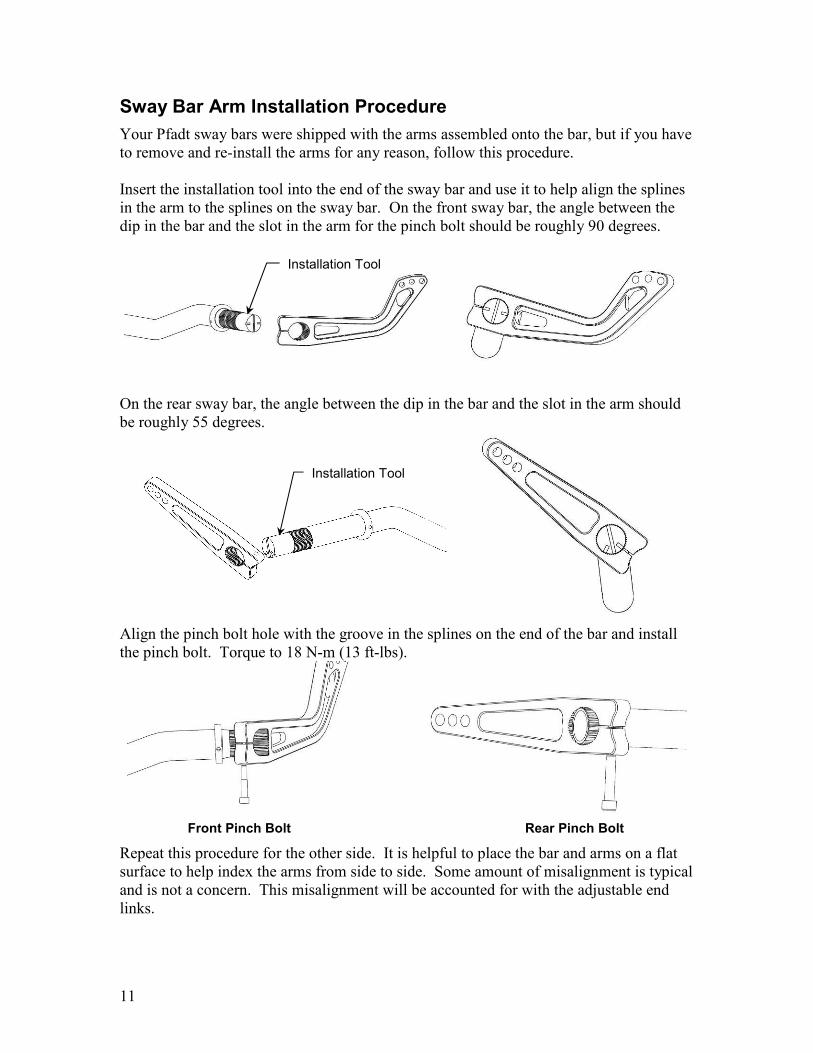
Sway Bar Arm Installation Procedure
Your Pfadt sway bars were shipped with the arms assembled onto the bar, but if you have
to remove and re-install the arms for any reason, follow this procedure.
Insert the installation tool into the end of the sway bar and use it to help align the splines
in the arm to the splines on the sway bar. On the front sway bar, the angle between the
dip in the bar and the slot in the arm for the pinch bolt should be roughly 90 degrees.
On the rear sway bar, the angle between the dip in the bar and the slot in the arm should
be roughly 55 degrees.
Align the pinch bolt hole with the groove in the splines on the end of the bar and install
the pinch bolt. Torque to 18 N-m (13 ft-lbs).
Front Pinch Bolt Rear Pinch Bolt
Repeat this procedure for the other side. It is helpful to place the bar and arms on a flat
surface to help index the arms from side to side. Some amount of misalignment is typical
and is not a concern. This misalignment will be accounted for with the adjustable end
links.
Installation Tool
Installation Tool
12
Sway Bar Tuning Guidelines
Sway bars are your largest tuning tool and are capable of affecting the balance of the car
during each phase of a corner: corner-entry, mid-corner and corner-exit. However, sway
bar tuning is especially useful for adjusting mid-corner behavior. Corner-entry and
corner-exit are considered transition periods. During these transition periods the shocks
are capable of modifying the balance of the car. At mid-corner, shock settings have no
affect on balance and adjustments are made with the sway bar. In other words, sway bars
could correct a corner-entry or corner-exit balance problem but, shocks can not correct a
mid-corner balance problem. This is the reason that sway bar tuning should ideally be
done during mid-corner.
When tuning sway bars it is best to find a long constant radius turn at which you can
incrementally increase speed until the limit of traction is found. There are three possible
scenarios at the limit of traction.
1. The front tires exceed their limit of traction first. This condition is commonly
called under-steer, push or tight.
2. The rear tires exceed their limit of traction first. This condition is commonly
called over-steer, tail-happy or loose.
3. The front and rear tires exceed their limit of traction at the same moment. This
condition is commonly called a four-wheel-drift or neutral balance.
After you have determined the behavior of the car it is possible to change this balance by
changing the sway bar settings.
Let’s take a look at case one for a moment. The front tires are being asked to carry a
cornering load higher than they are capable of while the rear tires are being asked to carry
a cornering load lower than they are capable of. By either moving the front sway bar to a
softer setting or the rear sway bar to a stiffer setting you will remove some of the
cornering responsibility from the front tires and add it to the rear tires.
The general rule of sway bar tuning is to soften the end that needs additional traction. It
is also equally as effective to stiffen the end that needs less traction. Typically in the
Corvette we tune with the rear sway bar because adjustments on the rear sway bar are
easier to perform at the track.
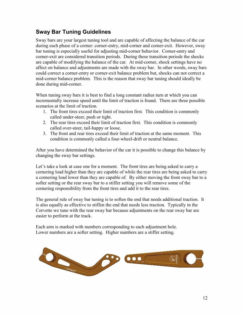
Each arm is marked with numbers corresponding to each adjustment hole.
Lower numbers are a softer setting. Higher numbers are a stiffer setting.

13
2315 Decker Lake Blvd.
Salt Lake City, UT 84119
888-972-2464
www.PfadtRacing.com


