

^PAOT/S^f
WVT-TR-76037
TECHNICAL -LIBRARY
PERFORMANCE OF CHROME-PLATED 105MM M68 GUN
TUBES WITH DISCARDING SABOT AMMUNITION
Allan A. Albright Glenn S. Friar Steven L. Morris
September 1976
BENET WEAPONS LABORATORY WATERVLIET ARSENAL
WATERVLIET, N.Y. 12189
TECHNICAL REPORT
AMCMS No. 3110.15.1100
Pron No. T1-5-59363-01-33-M7
APPROVED FOR PUBLIC RELEASE: DISTRIBUTION UNLIMITED

DISPOSITION
Destroy this report when it is no longer needed. Do not return it
to the originator.
DISCLAIMER
The findings in this report are not to be construed as an official
Department of the Army position unless so designated by other authorized
documents.

SECURITY CLASSIFICATION OF THIS PAGE (Whm Dmtm Bnfnd)
REPORT DOCUMENTATION PAGE t. REPORT NUMBER
WVT-TR-76037 2. GOVT ACCESSION NO.
READ INSTRUCTIONS BEFORE COMPLETING FORM
3. RECIPIENT'S CATALOG NUMSKR
4. TITLE f«njSSub«He)
PERFORMANCE OF CHROME-PLATED 105MM M68 GUN TUBES WITH DISCARDING SABOT AMMUNITION
5. TYPE OF REPORT A PERIOD COVERED
6. PERFORMING ORG. REPORT NUMBER
AlfanrAl bright Glenn S. Friar Steven L. Morris
a. CONTRACT OR GRANT NUMBERfaJ
9. PERFORMING ORGANIZATION NAME AND ADDRESS Benet Weapons Laboratory Watervliet Arsenal, Watervliet, NY 12189 SARWV-RDT
10. PROGRAM ELEMENT, PROJECT. TASK AREA ft WORK UNIT NUMBERS
AMCMS 3110.15.1100 PRON Tl-5-59363-01-33-M7
LI. CONTROLLING OFFICE.N AME. AND ADDRESS Project Manager, MbO Tank Development ATTN: AMCPM-M60TD/AMSTA-EBM Warren, MI 48092
12. REPORT DATE
September 1976 13. NUMBER OF PAGES
44 14. MONITORING AGENCY NAME ft AOORESSfff t/tfferanf from Controltlng OUlce)
US Artny Armament Command Rock Island,- IL 61201
15. SECURITY CLASS, (of thlm nport)
UNCLASSIFIED 15«. DECLASSIFICATION/DOWNGRADING
SCHEDULE
16. DISTRIBUTION STATEMENT (ol thia Report)
Approved for public release; distribution unlimited.
17. DISTRIBUTION STATEMENT (ol the abatract entered In Block 20, It different from Report)
18. SUPPLEMENTARY NOTES
19. KEY WORDS (Continue on reverse aide if neceaamrjr and identify by block number)
Chrome plated gun barrels Aimiunitlon Wear
Chrome plating Wear resistance Guns Tanks (Combat Vehicles) Gun barrels
Ordnance Coating
Erosion Ammunition dispersion
20. ABSTRACT (Contlnum on rttverca aidto if nmc^mmmry mnd identify by block numbmr)
This report describes testing to determine the feasibility of chrome plating the bore of 105mm M68 Gun Tubes to reduce wear conditions which affect performance of the M392A2 Armor Piercing Discarding Sabot (APDS) Projectile and similar rounds. Two chrome plated tubes were prepared and, with a standard tube for con- trol, fired to monitor relative performance. Based on several factors, it is concluded that special characteristics and sensitivities of M392-type projectiles result in a tendency toward degraded performance in chrome plated tubes, (over)
DD ,^ FORM AM 73 1473 EDfTION OF t NOV 65 IS OBSOLETE
SECURITY CLASSIFICATION OF THIS PAGE (irh«j Data Bntered)

SECURITY CLAMIFICATIOM OF TMI« PA«K<1W>— Oatm
20. ABSTRACT (Continued)
Recommendations are made to defer use of chrome plating 1n the M68 until factors affecting performance are fully identified through an exploratory development program.. r ^ K
tKCURITY CLASSIFICATION OF THIS PAGEflThen Data Enterad)

ACKNOWLEDGEMENT
The authors gratefully acknowledge the efforts and cooperation of
the many individuals who contributed to the performance evaluation
described in this report. Mr. Albert Schumacher and Mr. James Cerqua,
Watervliet Arsenal Operations Directorate, assisted in preparing the
gun tubes for testing. Mr. V. Peter Greco, Benet Weapons Laboratory
Research Directorate, administered the bore plating operation.
Mr. J. William Schweiker, Benet Weapons Laboratory Development and
Engineering Directorate, assisted in interpreting and reducing the
test firing data.

TABLE OF CONTENTS
PAGE
REPORT DOCUMENTATION PAGE, DD FORM 1473
ACKNOWLEDGEMENT 1
INTRODUCTION 1
BACKGROUND 3
DESCRIPTION OF TEST 5
FIRING RECORD 7
ANALYSIS OF DATA 11
CORRECTED IMPACT DATA 13
FILM DATA 17
CONCLUSIONS 25
RECOMMENDATIONS 26
APPENDIX A: STAR GAUGE AND BORESCOPE INSPECTIONS 27
APPENDIX B: PROJECTILE FLIGHT CHARACTERIZATIONS 32
n

LIST OF ILLUSTRATIONS
FIGURE PAGE
1. SECTIONAL VIEW OF TYPICAL APDS-T 12
PROJECTILE
2. TARGET IMPACTS-FULL LENGTH PLATED TUBE 14
3. TARGET IMPACTS-PARTIAL LENGTH PLATED TUBE 15
4. TARGET IMPACTS-UNPLATED TUBE 16
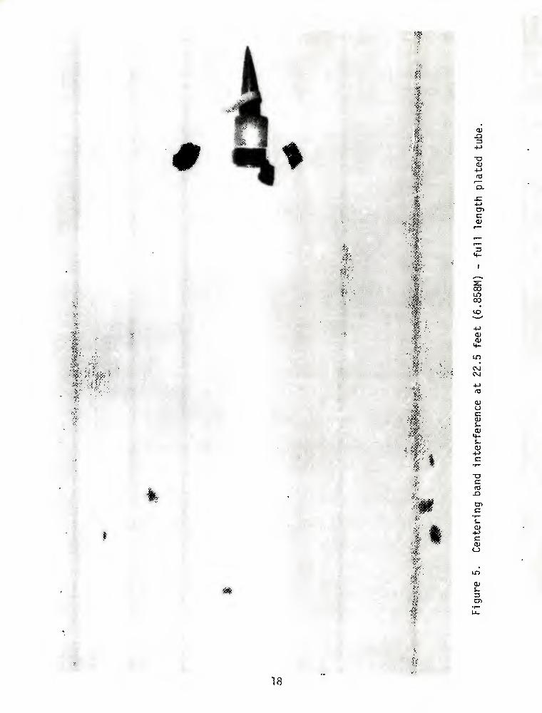
5. CENTERING BAND INTERFERENCE AT 22.5 FEET (6.858M)- 18
FULL LENGTH PLATED TUBE
6. SUBPROJECTILE YAW OVER 8° AT 50 FEET (15.24M)- 19
FULL LENGTH PLATED TUBE
7. CENTERING BAND INTERFERENCE AT 22.5 FEET (6.858M)— 20
PARTIAL LENGTH PLATED TUBE
8. LATE PETAL DISCARD AT 50 FEET (15.24M)—PARTIAL 21
LENGTH PLATED TUBE
9. CENTERING BAND INTERFERENCE AT 22.5 FEET (6.858M)— 22
UNPLATED TUBE
10. YAW OVER 8° AT 50 FEET (15.24M)-UNPLATED TUBE 23
m
LIST OF TABLES
JABLE PAGE
, 1. HORIZONTAL AND VERTICAL IMPACT DISPERSION 8
2. MUZZLE VELOCITIES 9
3. CIRCULAR IMPACT ERRORS 17
4. TARGET IMPACT DISPERSIONS WITH CENSORING OF 24
ABNORMAL PROJECTILE FLIGHT IMPACTS
Al. STAR GAUGE MEASUREMENTS AT COMPLETION OF 29
TESTING-FULL LENGTH PLATED TUBE
A2. STAR GAUGE MEASUREMENTS AT COMPLETION OF 30
TESTING—PARTIAL LENGTH PLATED TUBE
A3. STAR GAUGE MEASUREMENTS AT COMPLETION OF 31
TESTING—UNPLATED TUBE
Bl. PROJECTILE FLIGHT CHARACTERISTICS-FULL 33
LENGTH PLATED TUBE
B2. PROJECTILE FLIGHT CHARACTERISTICS-PARTIAL 34
LENGTH PLATED TUBE
B3. PROJECTILE FLIGHT CHARACTERISTICS-UNPLATED TUBE 35
IV
INTRODUCTION
This report describes the results of recent testing to evaluate the
performance of spin stabilized, armor piercing, discarding sabot (APDS)
ammunition in chrome-plated 105mm M68 gun tubes. Earlier tests have
indicated that, while chrome plating can significantly retard bore
wear rates, there is a tendency toward degraded APDS accuracy in
plated tubes.
Chrome plating has been considered as a deterrent to the evolution
of secondary wear signatures in the M68 tube. Secondary wear is a
highly variable erosion condition observed in the first 12 inches of
rifled length. Early in tube life, this wear is observed as a diam-
etral expansion at the origin of rifling (O.R.), followed by a con-
traction and a second expansion before tapering to negligible wear with
increasing distance from the O.R. Conditions in the region of this
second diametral expansion are called secondary wear. Later in life,
the wear expansion starts at the O.R. and increases to a maximum level
between 8 and 12 inches forward of the O.R. before tapering out to
negligible wear. The point of maximum down-bore expansion is also
called secondary wear.
Secondary wear is the result of erosive characteristics of HEAT-
type ammunition. The normal consumption of ammunition in field use has
been approximately 73% HEAT, 26% HEP and less than 1% APDS. HEP-type
ammunition has a very small erosive effect, with a corresponding tube wear
life greater than 15,000 rounds. In view of the large proportion of

HEAT-type ammunition consumed, it is apparent why field surveys have
shown secondary wear to be prevalent in fielded M68 tubes. APDS ammu-
nition also creates secondary wear, but it is insignificant in com-
parison to the HEAT-type erosion.'
Extensive accuracy firing tests with production tubes have shown
that APDS ammunition is sensitive to secondary wear conditions, with
drastically degraded performance occurring under certain conditions.2
Resolution of accuracy considerations is a necessary prerequisite to
the use of chrome plating as a solution to secondary wear problems.
^Watervliet Arsenal Report No. WVT-TR-75047, Analysis of Wear Data from 105mm M68 Gun Tubes in Field Service, July 1975.
^Aberdeen Proving Ground Report No. FR-P-82476, 22 April 1975.

BACKGROUND
In 1959 and 1960, the United Kingdom tested one 105mm and four 20-
pounder chrome-plated gun tubes for firing accuracy. The conclusion
from this limited testing was that, while accuracy was not as good in
an unplated control tube, it did improve as the unplated tube wore.
The accuracy of the plated tubes remained constant.^''^ In 1962,
Watervliet Arsenal chrome plated three 105mm T254 tubes for accuracy
testing. Test results indicated that the plated tubes gave poorer
accuracy performance than unplated tubes.^
Recent testing, in which the 105mm M68 gun tube has been used as a
vehicle to evaluate platings, indicates that an M68 tube plated with
a 0.010 inch thick layer of chrome will develop negligible origin of
rifling wear and minor secondary wear, when firing HEAT-type ammunition.
Thus, since chrome plating has demonstrated the potential for reducing
secondary wear conditions, the possibility of degraded accuracy per-
formance with APDS ammunition is the determining factor for incorpo-
rating chrome plating in the M68 gun tube.
The remainder of this report will describe the special test program,
administered by Watervliet Arsenal, to evaluate the accuracy potential
of APDS ammunition in chrome-plated M68 gun tubes. This program was
designed and implemented as the preliminary phase in the development
Ordnance Board Proceeding, Q8837, 16 June 1959. ^Minutes of Meeting at RARDE, FPA/16/02, November 1960. ^USA TECOM Report No. DPS-469, Accuracy and Erosion Studies of Modified T254 Series Gun Tubes for 105mm Gun, M68, APG, 1962.

of wear resistant coatings for the M68 tube. Three possible outcomes
of this phase were projected. Firsts chrome plating could show no ad-
verse effect on accuracy. Given this outcome, a full-scale Product
Improvement Project (PIP) for production plating would be initiated.
Second, the chrome plate configuration could be found less than optimum,
necessitating a major research and development program to prepare an
alternate plating. Third, disadvantages or shortcomings of plated
tubes could be found to outweigh any advantage they might offer, and
the program would be dropped as a solution to APDS erratic performance.

DESCRIPTION OF TEST
Originally, accuracy testing was to consist of comparing a
standard production tube, a tube with full bore length chrome plating,
and a third tube with full bore length chrome plating over an inter-
mediate cobalt alloy plating. Due to anticipated limitations in the
availability of production quantities of cobalt alloy, the intermediate
cobalt alloy plated tube was not prepared for testing, being replaced
by a tube with a partial length chrome plating. A partial length
plated tube offers several advantages in production, including reduced
cost and process time. Also, with the possibility of frictional inter-
action between the bore surface and APDS projectiles strongly influ-
encing dispersion characteristics, the partial length plating presents
less chromed bore surface area, while maintaining a wear resistant
surface in the region of secondary wear.
Two 105mm M68 gun tubes were prepared under the supervision of the
Physical Science Division, Benet Weapons Laboratory. A 0.010 inch
thick chrome plating was applied to the full length of the bore of the
first tube and chrome plate from the forcing cone to a distance of
thirty inches into the rifled region of the bore in the second tube.
Final bore diameters of both tubes were that of production tubes.
These two tubes, and a standard production tube, were delivered to
Aberdeen Proving Ground (APG), Maryland in February 1976.

Accuracy firing was conducted by the Materiel Test Directorate
during March and April 1976.^ Three replications, each consisting of a
ten round group from each of the three test tubes, were conducted to
measure target dispersion. All ammunition used in the test was
Cartridge, 105mm: APDS-T M392A2, from Lot MA 9-4 (MPTS Lot FLP-2-2-71),
conditioned to +70''F {+21.11°C). This ammunition lot was chosen as
typical of United States production service ammunition. All rounds
were fired at a 20-by-20-foot (6.096-by-6.096 meter) vertical target
at a range of 1,000 meters. Recorded data included target impacts,
muzzle velocity, wind velocity and direction, and smear camera photo-
graphs, at 22.5 and 50 feet (6.858 and 15.240 meters) from the muzzle,
for each round fired. Prior to initiation of the test, a 10 mph
(16 kmh) wind velocity limit was specified.
Replications were performed on 23 March 1976, 29 March 1976, and
6 April 1976. A representative from Watervliet Arsenal was present
for the 23 March firing. The firing record and subsequent data analysis
are discussed in the following two sections.
^USA TECOM Report No. APG-MT-4802, Product Improvement Test of Gun Tube, 105mm M68 Tube Wear Resistant Plating Accuracy Phase, APG, May 1976, referred to hereafter as USA TECOM Report No. APG-MT-4802.

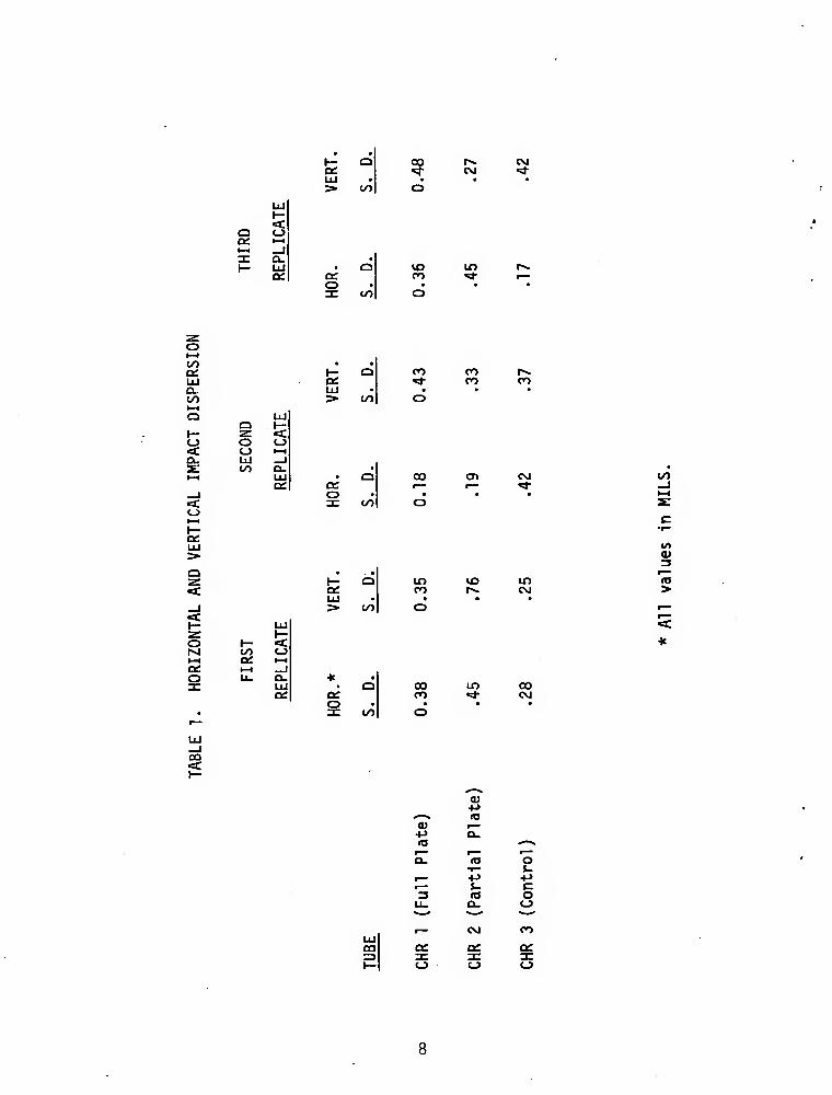
FIRING RECORD
Firing data is detailed in the report prepared by APG.^ Table 1 is
excerpted from this report and shows horizontal and vertical standard
deviations of the impact coordinates for each ten round group.
Two-way analysis of variance (ANOVA) and F-tests on variance ratios
(pooled over replicates) are unable to detect significant differences
among horizontal standard deviations at the 5% level. No significant
differences among vertical standard deviations are detected using
two-way ANOVA. The F-test detects a just significant difference be-
tween the pooled standard deviations for CHR 2 (partial plate) and
CHR 3 (unplated). This can be attributed to the 0.76 mil vertical
standard deviation for CHR 2 in the first replicate.
Muzzle velocities, and associated standard deviations in velocities,
for each tube and replicate are shown in Table 2. Significant differ-
ences in velocities, at the 5% level, can be shown to exist among tubes
and among replicates. The average velocity of CHR 1 (full length) was
significantly higher than that of CHR 3 (unplated) and the average
velocity of CHR 1 and CHR 2, taken together, was significantly higher
than that of CHR 3. The average velocity for the second replicate was
significantly higher than both the first and third replicates, taken
together or separately. At the 10% level, ANOVA failed to detect any
significant differences among the velocity standard deviations for the
three tubes.
7USA TECOM Report No. APG-MT-4802.
CO cvi
CM
U~)
a o l-H _i n: Q. I— UJ a:
O t/i
CO
CO • • C3[: »- O CO LU Q: •* a. LU • • to >■ CO o 1—1 Q
a UJ 1—
H- ■z. <c O o «_J < o l-H Q. LU _l s: to Q. % t—1 LU • Q 00
DC Q: _i o • • < 3C CO o o
n CO CO
<T» c\j \n
LU > o z <:
00
in CO
LD C\J
o 1- <C M 00 o »-H 0£. l-H oe. 1—1 _l o u. Q. * • 3: LU O 00 Lf> 00
CC di n ^ CVJ o • • • •
• 31 CO o
3
>
ca
<a
<u la
lO
CL.
o s- +J
o
CQ
o
CVI
CJ
CO

llj 0£
o
en
to a ot Ot Oi O) CO o
•sl- o^ ^ CO <NI
vo CO
^ UJ trt (.0 a 2 E UJ > to <■ a
M
r*. (O CO r— lO o
o^ O r>. CTV CM <T> 00 cn 00 00 00 00 00 <d- CO '* 00 ** ^ r— «:*• "* r—
00
o
M
UJ a h- «C • o I/O 1—1 _l o. UJ a: o z: Ul o CD
UJ 2 CO UJ
> <C
to Q.
to a
to a
a
o CNJ
vo U3
00
CM
CM 00
CO
r>. CM
CO
CM «* O CT> cn ^ «d- I—
CM in •
o CO o <T» cn ^ «*
o o CT> CJ> CO ^
CM
CO
Ul OH
to a:
CO
CD
a
to
cr> CO o tn rx. rs.
t— 00 CO CM xd- • • • • • • to 3. r*. lO o CO
to to a 00 B ■
00 cn 00 00
to 00 ^ a. ^ r—
to
CO CO CO CO 00 ^ "Si- 1—
cn in CO 00 00 CO >* »3- r—
CO
01 •M
^—% <e 0) r— +J a. Id f" r>« r*" a. le 2 ^M •M +* r* s. c 3
U. a. 5 I— CM CO
oe C£ ec 3C ac X O o o

Each of the three gun tubes in the test sustained a total of
thirty-seven rounds; one proof round, the three ten round groups, and
two warmer rounds prior to each ten round group. Star gauge measure-
ment and borescope inspection were performed after proof firing and
after the completion of firing. A summary of these results is in
Appendix A. Progressive chipping, flaking, and stripping of chrome
in the full plate tube (CHR 1) was noted in the two inspections per-
formed on this tube.
10

ANALYSIS OF DATA
Upon completion of test firings, additional data analysis was con-
ducted at Watervliet Arsenal to prepare a qualitative assessment of the
performance of the three gun tubes involved in the test. In this
analysis, emphasis was placed on the relative performance of the three
tubes, including segregation of ammunition related performance factors.
Figure 1 shows a cross-sectional view typical of the projectile in
the M392/M724/M728 models of discarding sabot ammunition. A variety of
par-ameters have been identified as related to the flight character-
istics of this projectile, including frictional interfaces between the
rotating and centering bands and the gun tube bore. Proper sub-
projectile attitude and petal discard, with associated centering band
functioning, upon shot ejection have been shown to be determining
factors in projectile flight.^
It is emphasized that the results of the firings discussed in this
report apply only to M392-type APDS projectiles and that it is not
correct to interpret these results relative to full bore diameter
projectiles (e.g. HEAT, HEP, and HVAP).
8APG Firing Record No. P-82488, Product Improvement Test of Cartridqe, 105mm, APDS-T, M392A2 (Mode of Failure), 29 August 1975.
11

UJ
o UJ
o DC a. H s
<
OJ
+-> o <u
■■-3 o S- Q.
I
Q Q.
O •r— Q.
+->
4-> u 0)
s- CD
< UJ z (0
12

Corrected Impact Data
Vertical target impacts recorded during test firing were corrected
for a standard muzzle velocity of 4850 fps (1478.28 mps). Variations
in local wind velocity and direction, and in air density, during firing
were neglected. Figures 2, 3, and 4 are plots of the impact coordinates
for each tube in the three replicates. Since this test addressed only
dispersion characteristics, the centers of impact are shown as common
for each of the three ten round groups for their respective tubes.
"Corrections for standard muzzle velocity had minor effect on
vertical impact standard deviations, reducing the value calculated for
one tube in the third replicate by 0.01 mil.
For convenience in comparison, the following discussion of impact
dispersion has been prepared in terms of circular error (CEP), with
values given corresponding to the radius of a circle drawn at the
center of impact and having an associated probability of including 50%
of the impacts.^ Table 3 shows circular errors associated with the
pooled impact data for each of the three test tubes.
For reference, the desired dispersion for the M60-series tank,
specified before type classification of either the M68 gun or the M60
tank, was horizontal and vertical standard deviations of 0.22 mils
(corresponding to a circular probable error of 0.26 mils). These
values have never been realized with any consistency; horizontal and
^his technique is discussed in Statistics Manual (E.L.Crow,F.A.Davies, and M.W. Maxfield, Dover Publications, Inc.,NY, 1960) with necessary approximations described in Chapter 26 of Handbook of Mathematical Functions (M.Abramowitz and I. A. Stegun, National Bureau of Standards, GPO, June 1964).
13

Figure 2. Target impacts--fun length plated tube.
14
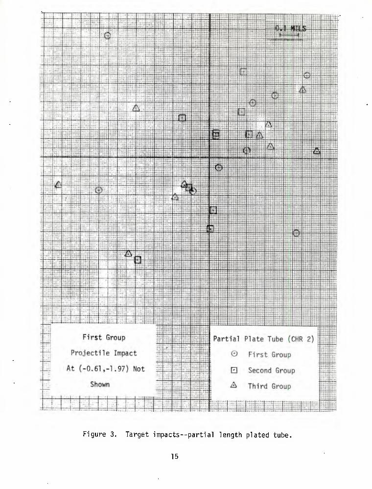
Figure 3. Target impacts--partial length plated tube.
15
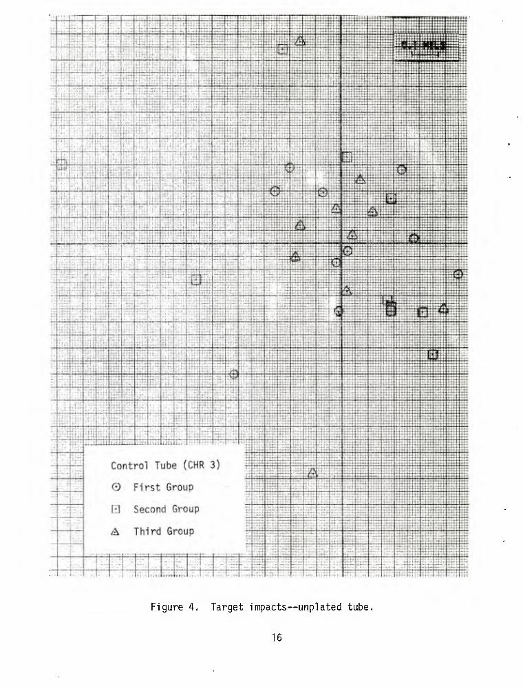
Figure 4. Target impacts—unplated tube,
16
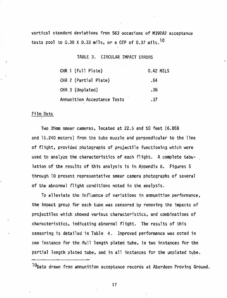
vertical standard deviations from 563 occasions of M392A2 acceptance
tests pool to 0.30 X 0.33 mils, or a CEP of 0.37 mils.^°
TABLE 3. CIRCULAR IMPACT ERRORS
CHR 1 (Full Plate) 0.42 MILS
CHR 2 (Partial Plate) .54
CHR 3 (Unplated) .38
Ammunition Acceptance Tests .37
Film Data
Two 35mm smear cameras, located at 22.5 and 50 feet (6.858
and 15.240 meters) from the tube muzzle and perpendicular to the line
of flight, provided photographs of projectile functioning which were
used to analyze the characteristics of each flight. A complete tabu-
lation of the results of this analysis is in Appendix B. Figures 5
through 10 present representative smear camera photographs of several
of the abnormal flight conditions noted in the analysis.
To alleviate the influence of variations in ammunition performance,
the impact group for each tube was censored by removing the impacts of
projectiles which showed various characteristics, and combinations of
characteristics, indicating abnormal flight. The results of this
censoring is detailed in Table 4. Improved performance was noted in
one instance for the full length plated tube, in two instances for the
partial length plated tube, and in all instances for the unplated tube.
''^Data drawn from ammunition acceptance records at Aberdeen Proving Ground.
17
iiii
T3 0)
+-> ra Q.
x: +-> en c
=1
CO
00
Oi 01
CM
4-*
OI o c <u s- <l> M- S- ttJ +J c
♦ x> c
cn
s_ cu
■M c o
<u i- C71
18

Ft f^pfi
•ii-.^k,-
<u X) 3 +J
T3 tt) +J (0
f-"
o. JC ** a* ,_ c m
1"^
r_ f-»
3 H-
t , , X «* Cvi .' •
'■
un
.' _ 01 ' -$ ^
i^"
'■;■'
O
(13 Ji o 00
0) .'' *>-<
•_' > o
■^ 'V j « f S-t ' AK: >. \'^ *^k,^
ml 41
lim ^ ■»->
o Of
•■-s o ' i- Q. ja * rs v^
UD
0) f s-
3 cn
4i :>■
19 #

3
4-> CD C
CL
00
us
OJ OJ
<4-
■;<K'
4-> ft)
OJ u c CU
OJ
s_ CD
-t-J c
«
c: S-
OJ
Of
.',»
20

3
■o
ns
C
03
Q.
4->
o
+->
■a
IB O t/1
-a
0) 4-> (T3
CO
i-
\ ^

•
-Q 3
+->
T3
« r—
C
s: CO to 00
1£5
4->
CSi
+->
<u o c
M- i- 0)
en c
a* -M C
en cy 1- 3 CD
22

rl -M
T3
CL C
CM
4_>
CU
o m 4^ ft3
00
i~
> o
>-
o
CU 5-
CD
23

TABLE 4. TARGET IMPACT DISPERSIONS WITH CENSORING OF ABNORMAL
PROJECTILE FLIGHT IMPACTS
CHARACTERISTIC 1
NUMBER CENSORED
CHR 1 CHR 2
CIRCULAR ERROR (MILS)
CHR 3 CHR 1 CHR 2 CHR 3
_ _ —,' - - 0.42 0.54 0.38
F 2 0 , 2 .42 .54 ,32
J 0 4 4 .42 .61 .30
K 4 7 2 .39 .46 .36
F, K 1 0 2 .43 .54 .32
J, K 0 3 4 .42 .49 .30
F. J, K 0 0 2 .42 .54 .32
1 F - Over 8° subprojectile yaw.
J - Late petal discard.
K - Centering band interference with subprojectile.
CHR 1 - Full length plated tube.
CHR 2 - Partial length plated tube.
CHR 3 - Unplated tube.
24
CONCLUSIONS
The two chrome-plated tubes show a tendency towards greater dis-
persion. This tendency is emphasized when projectile flights with
characteristics which have been shown to adversely influence impact
dispersion are censored from the performance calculations. When this
ammunition variable is alleviated, the relative performance of the un-
plated control tube consistently improves; this consistent improvement
does not occur with the plated tubes.
The hypothesis of frictional characteristics of the bore surface
affecting performance of APDS ammunition is supported by the evidence
of higher muzzle velocities encountered with the plated tubes. The
fact that higher muzzle velocities were measured in both tubes tends
to indicate that the frictional influence is manifested within the
first thirty inches of projectile travel.
Based on the severe chipping, flaking, and stripping encountered
in the full length plated tube, its performance is considered un-
satisfactory. The plating in the partial length plated tube remained
intact and offers advantages in speed and ease of fabrication.
25

RECOMMENDATIONS
1. The incorporation of wear resistant coatings to control levels
of secondary bore wear in the lOSmm M68 gun tube should be deferred
until the interaction of APDS projectile functioning and bore coatings
is fully established.
2. An exploratory development program, addressing the interaction
of bore coatings and the APDS projectile, should be established.
3. The advantages of partial length plating over full length
plating should be considered in other plating programs.
26

APPENDIX A
STAR GAUGE AND BORESCOPE INSPECTIONS
The following borescope inspection report is taken from the APG
letter report.^
1Q5MM M68 TUBE CHR 1 AFTER FIRING 1 ROUND
"BORESCOPED: (Chrome plated between 21.60" from rear face of tube
and muzzle.)
Light scratches, stains, and deposits throughout chamber, bore,
and rifling. Seventeen lands at various times in the forcing cone
24.60" from rear face of tube have the chrome plating chipped off on
the non-driving side. Chrome removed from edges of lands on both
driving and non-driving sides at various times and distances throughout
bore. Chrome flaked from breech one-third of all bore evacuator holes.
Lands in muzzle .25" of tube have chrome chipped from both driving and
non-driving edges."
1Q5MM M68 TUBE CHR 1 AFTER FIRING 37 ROUNDS
"BORESCOPED: (Chrome plated between 21.60" from rear face tube
and muzzle.)
Light scratches, stains, carbon and other deposits throughout
chamber and bore. Lands in forcing cone 24.60" from rear face tube
(RFT) have chrome chipped from non-driving side. Chrome chipped.
11 USA TECOM Report No. APG-MT-4802,
27

flaked and stripped from lands at various times and distances throughout
bore, more pronounced between 9:00 and 3:00 o'clock. Chrome flaked
from edges of bore evacuator holes with light erosion in base metal.
Lands in muzzle .25" of tube have chrome chipped from both driving and
non-driving edges."
Star gauge measurements of the tube bore of each of the gun tubes,
taken at the completion of test firings, are shown in Tables Al, A2,
and A3.
28

TABLE Al. STAR GAUGE MEASUREMENTS AT COMPLETION OF
TESTING—FULL LENGTH PLATED TUBE
DISTANCE FROM DISTANCE FROM REAR FACE OF VERTICAL VERTICAL REAR FACE OF VERTICAL VERTICAL TUBE (INCHES) LAND GROOVE TUBE (INCHES) LAND GROOVE
25.25 0.001 -0.001 59 0.000 0.001 25.5 .000 1 60 - .001 i 26 .000
■1 66.5 1 J I
27 - .001 72.5 il 28 1 78.5 1 1 1 • 29 i ■
84.5 T T 30 90.5 - .001 .001 31 ■ 96.5 .011 .000 32 102.5 - .001 i 33 108.5 i i I
34 114.5 il
35 ' 120.5 I m
36 126.5 1 "37 I 132.5 - .001 38 j f 138.5 .008 39 144.5 .006 40 i - .001 150.5 .001 41 .0 00 156.5 A 42 i 1 162.5 I •
1 r 43 1 I 168.5 J 44 i
174.5 .000 45 180.5 .001 46 186.5 A 47 192.5
1 t
48 198.5 49 200.5 1 t
50 202.5 T 51 204.5 .001 52 205.5 - .001 53 • r 206.5 .000 54 f 207.5 1 r .000 55 .000 208.5 f .000 56 1 1 .001 209.5 .001 .001 57 f .001 210 - .001 - .002 58 - .0 01 .0 01
29
TABLE A2. STAR GAUGE MEASUREMENTS AT COMPLETION OF
TESTING—PARTIAL LENGTH PLATED TUBE
DISTANCE FROM DISTANCE FROM REAR FACE OF VERTICAL VERTICAL REAR FACE OF VERTICAL VERTICAL TUBE (INCHES) LAND GROOVE TUBE (INCHES) LAND GROOVE
25.25 -0.004 -0.004 59 0.001 0.002 25.5 - .004 - .004 60 ,001 A 26 - .004 - .004 66.5 .000 1 1
27 - .003 - .004 72.5 i 28 - .003 - .003 78.5 I 29 - .001 - .002 84.5 t 30 A A 90.5 .000 31 T ■ ■
96.5 .001 32 f 102.5 i 33 - .001 1 I 108.5 1 1
34 .000 f 114.5 35 .000 - .002 120.5 36 .000 - .001 126.5 37 .000 - .001 132.5 38 .001 - .001 138.5 1 r 39 1 - .001 144.5 f 40 J I .000 150.5 .001 41 1 156.5 .000 42
J I 162.5 .000
43 168.5 .000 44 174.5 .000 45 1 1 180.5 .001 46 T 186.5 A 47 1 1 .000 192.5
• •
48 f .001 198.5 1 f
49 .001 200.5 1 50 .000
1 , 202.5 .001 51 .000 11 204.5 .002 52 .001 1 205.5 A 53 - .002 .001 206.5 «
54 .002 .004 207.5 55 .006 .005 208.5 t 1 r 56 .003 .004 209.5 f 57 .002 .003 210 .002 0.002 58 .C )01 .( }02
30

TABLE A3. STAR GAUGE MEASUREMENTS AT COMPLETION OF
TESTING—UNPLATED TUBE
DISTANCE FROM DISTANCE FROM REAR FACE OF VERTICAL VERTICAL REAR FACE OF VERTICAL VERTICAL TUBE (INCHES) LAND GROOVE TUBE (INCHES) LAND GROOVE
25.25 0.005 0.002 59 0.001 0.000 25.5 .003 .002 60 A .000 26 .002 .001 66.5 I .001 27 .002 .001 72.5 f A 28 .002 .001 78.5 .001
1 1
29 .001 .C 00 84.5 .002 30 31 i i ( \ 90.5
96.5 ♦ 32 102.5 33 108.5 34 114.5 35 120.5 36 126.5 37 132.5 38 138.5 39 144.5 40 150.5 41 156.5 1 1 42 162.5 ? 43 168.5 .002 44 174.5 ,001 45 180.5 A 46 186.5
ti
47 192.5 1 ■
48 198.5 T 49 200.5 .001 50 202.5 .002 51 204.5 A 52 205.5 I 1 • 53 206.5 T T 54 207.5 .002 .001 55 f
208.5 .001 .002 56
^ r 1 r 209.5 .001 .002
57 T 210 .001 .000 58 .0 01 .0 00
31
APPENDIX B
PROJECTILE FLIGHT CHARACTERIZATIONS
Smear camera photographs were analyzed to identify flight charac-
teristics of projectiles fired in the dispersion testing. Tables Bl,
B2, and B3 describe the results of this analysis.
32

TABLE Bl. PROJECTILE FLIGHT CHARACTERISTICS-FULL LENGTH PLATED TUBE
CHARACTERISTICi 1 CHARACTERISTIC
22.5 FT 50 1 -T 22.5 FT 50 FT
ROUND (S.858M) (15.; IW) ROUND (6.858M) (15.24M)
3 D, S E 20 D, S D, S
4 D. S D, S 21 D, S F
5 E D, S 22 D, S D, S
6 D, S D, s 23 E D, S
7 E D, s 24 D, S D, S
8 D, S D, s 27 K D, S
9 E D, s 28 K E
10 A, D E 29 D, S D, S
n D, S D, s 30 E E
12 D, S D, s 31 K F
, 15 D, S D, s 32 D, S E
16 E E 33 D, S E
17 E D, s 34 E E
18 D, S D, s 35 D, S D, S
19 E E 36 K E
1A- Subprojectile not centered in sabot. S - Satisfactory.
c - Rotating band on sabot • J - Late petal discard.
D - 0° to 4° subprojectile yaw. K - Centering band
E - 5'' to 8" subprojectile yaw. interference with
F - Over 8° subprojectile . yaw. subproject ile.
33

TABLE B2. PROJECTILE FLIGHT CHARACTERISTICS-PARTIAL LENGTH PLATED TUBE
CHARACTERISTIC' CHARACTERISTIC
22.5 FT 50 FT 22.5 FT 50 FT
ROUND (6.858M) (15.24M) ROUND (6.858M) (15.24M)
3 D. S D. S 20 D, S D, S
4 K D. S 21 D, S D, S
5 A D, S 22 K D, S
6 D, S D, S 23 D, S D, S
7 D, S D, 5 24 D, S D, S
.« D, S D, S 27 K D, S
9 D, S D, S 28 D, S D, S
10 D, S D, S 29 D, S D. S
n J E, J 30 J, K D. S
12 D, S D, S 31 K D. S
15 D, S D, S 32 D, S D, S
16 D, S D. S 33 D, S D, S
17 D, S D, S 34 D. S D, S
18 D, S D. S 35 J, K E
19 D, S D, S 36 J, K D. J
^A - Subprojectile not centered in
sabot.
C - Rotating band on sabot.
D - 0" to 4° subprojectile yaw.
E - 5' to 8° subprojectile yaw.
F - Over 8° subprojectile yaw.
S - Satisfactory.
J - Late petal discard.
K - Centering band interference
with subprojectile.
34
TABLE B3. PROJECTILE FLIGHT CHARACTERISTICS--UNPLATED TUBE
CHARACTERISTIC CHARACTERISTIC
22.5 FT 50 FT 22.5 FT 50 FT
ROUND (6.858M) (15.24M) ROUND (6.858M) 15.24M)
3 D, S D, S 20 D, S D, S
4 D, S D, S 21 D, S D. S
5 D, S D, S 22 K E
6 D, S D. S 23 D, s D, S
7 D, S D, S 24 J, K E
•8 D, S D, S 27 D. S D. S
9 D' S D, S 28 K D, S
10 D, S D, S 29 J, K D, S
11 D, S D, S 30 D, S D. S
12 0, K F 31 D, S D, S .
15 J. K F 32 D, S D. S
16 D, S D, S 33 D, S D. S
17 D. S D, S 34 D, S D, S
18 D, S D, S 35 D, S D, S
19 D, S D, S 36 D, S D, S
1A- Subprojectile not centered F - Over 8° subprojecti le yaw.
in sabot. S - Sati. 5factory.
c - Rotating band on sabot. J - Late peta 1 discard
D - 0° to 4° subprojectile yaw. K - Centering band interference
E - 5° to 8° subprojectile yaw. with subprojectile
35

EXTERNAL DISTRIBUTION LIST
1 copy to each May 1976
CDR US ARMY MAT § DEV READ. COMD ATTN: DRCRD
DRCRD-TC DRCRD-W
5001 EISENHOWER AVE ALEXANDRIA, VA 22304
OFC OF THE DIR. OF DEFENSE R^E ATTN: ASST DIRECTOR MATERIALS THE PENTAGON WASHINGTON, D.C. 20315
CDR US ARMY TANK-AUTM\' COMD ATTN: AMDTA-UL
AMSTA-RKM MAT LAB WARREN, MICHIGAN 48090
CDR PICATINNY ARSENAL ATTN: SARPA-TS-S
SARPA-VP3 CPLASTICS TECH EVAL CEN)
DOVER, NJ 07801
CDR FRANKFORD ARSENAL ATTN: SARFA PHILADELPHIA, PA 19137
DIRECTOR US ARMY BALLISTIC RSCH LABS ATTN: AMXBR-LB ABERDEEN PROVING GROUND MARYLAND 21005
CDR US ARMY RSCH OFC (DURHAM) BOX CM, DUKE STATION ATTN: RDRD-IPL DURHAM, NC 27706
CDR WEST POINT MIL ACADEMY ATTN: CHMN, MECH ENGR DEPT WEST POINT, NY 10996
CDR US ARMY ARMf COMD ATTN: AMSAR-PPW-IR
AMSAR-RD AMSAR-RDG
ROCK ISLAND, IL 61201
CDR US ARMY ARMT COMD FLD SVC DIV ARMCOM ARMT SYS OFC ATTN: AMSAR-ASF ROCK ISLAi^D, IL 61201
CDR US ARMY ELCT COMD FT MONMOUTH, NJ 07703
CDR REDSTONE ARSENAL ATTN: AMSMI-RRS
AMSMI-RSM ALAB.AMA 35809
CDR ROCK ISLAND ARSENAL ATTN: SARRI-RDD ROCK ISLAND, IL 61202
CDR US ARMY FGN SCIENCE 5 TECH CEN ATTN: AMXST-SD 220 7TH STREET N.E. CHARLOTTESVILLE, VA 22901
DIRECTOR US ARMY PDN EQ. AGENCY ATTN: AMXPE-MT ROCK ISLAND, IL 61201
CDR HQ, US ARMY AVN SCH ATTN: OFC OF THE LIBRARIAN FT RUCKER, ALABAMA 36362
EXTERNAL DISTRIBUTION LIST (Cont)
1 copy to each
CDR US NAVAL WPNS LAB CHIEF, MAT SCIENCE DIV ATTN: MR. D. MALYEVAC DAHLGREN, VA 22448
DIRECTOR NAVAL RSCH LAB ATTN: DIR. MECH DIV WASHINGTON, D.C. 20375
DIRECTOR NAVAL RSCH LAB CODE 26-27 (DOCU LIB.! WASHINGTON, D.C. 20375
NASA SCIENTIFIC § TECH INFO FAC PO BOX 8757, AITN: ACQ BR BALTIMORE/WASHINGTON INTL AIRPORT MARYLAND 21240
2 copies to each
CDR US ARMY MOB EQUIP RSCH § DEV COMD ATTN: TECH DOCU CEN FT BELVOIR, VA 22060
CDR US ARMY MAT RSCH AGCY ATTN: AMXMR - TECH INFO CEN WATERTOWN, MASS 02172
CDR WRIGHT-PATTERSON AFB ATTN: AFML/MXA OHIO 45433
CDR REDSTONE ARSENAL ATTN: DOCU § TECH INFO BR ALABAMA 35809
DEFENSE METALS INFO CEN BATTELLE INSTITUTE 505 KING AVE COLUMBUS, OHIO 43201
MANUEL E. PRADO / G. STISSER LAWRENCE LIVERMORE LAB PO BOX 808 LIVERMORE, CA 94550
DR. ROBERT QUATTRONE CHIEF, MAT BR US ARMY R§S GROUP, EUR BOX 65, FPO N.Y. 09510
12 copies
CDR DEFENSE DOCU CEN ATTN: DDC-TCA CAMERON STATION ALEXANDRIA, VA 22314
NOTE: PLEASE NOTIFY CDR, WATERVLIET ARSENAL, ATTN: SARWV-RT-TP, WATERVLIET, N.Y. 12189, IF ANY CHANGE IS REQUIRED TO THE ABOVE,

WATERVLIET ARSENAL INTERNAL DISTRIBUTION LIST May 1976
No. of Copies
COMMANDER 1
DIRECTOR, BENET WEAPONS LABORATORY 1
DIRECTOR, DEVELOPMENT ENGINEERING DIRECTORATE 1 ATTN: RD-AT 1
RD-MR 1 RD-PE 1 RD-RM 1 RD-SE 1 RD-SP 1
DIRECTOR, ENGINEERING SUPPORT DIRECTORATE 1
DIRECTOR, RESEARCH DIRECTORATE 2 ATTN: RR-AM 1
RR-C 1 RR-ME 1 RR-PS 1
TECHNICAL LIBRARY 5
TECHNICAL PUBLICATIONS 5 EDITING BRANCH 2
DIRECTOR, OPERATIONS DIRECTORATE 1
DIRECTOR, PROCUREMENT DIRECTORATE 1
DIRECTOR, PRODUCT ASSURANCE DIRECTORATE 1
PATENT ADVISORS 1


