

Philips Halogen Lamps
Product Information3222 635 3662112/02Printed in the Netherlands
Information forOriginal Equipment
Manufacturers
Provisional
HalogenALinear double-endedPAR HalogenALV capsulesDichroicClickline
1
Contents
1
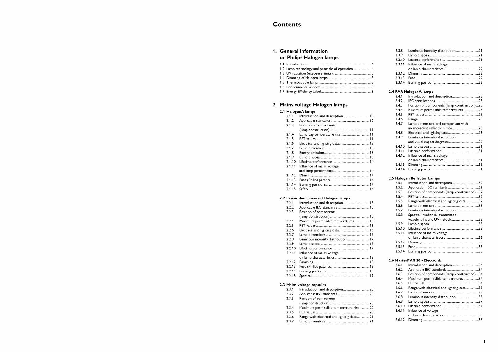
1. General information on Philips Halogen lamps1.1 Introduction................................................................................41.2 Lamp technology and principle of operation ......................41.3 UV radiation (exposure limits)...............................................51.4 Dimming of Halogen lamps.....................................................81.5 Thermocouple lamps................................................................81.6 Environmental aspects .............................................................81.7 Energy Efficiency Label .............................................................8
2. Mains voltage Halogen lamps2.1 HalogenA lamps
2.1.1 Introduction and description................................102.1.2 Applicable standards...............................................102.1.3 Position of components
(lamp construction) ................................................112.1.4 Lamp cap temperature rise...................................112.1.5 PET values .................................................................112.1.6 Electrical and lighting data .....................................122.1.7 Lamp dimensions.....................................................132.1.8 Energy emission .......................................................132.1.9 Lamp disposal ...........................................................132.1.10 Lifetime performance .............................................142.1.11 Influence of mains voltage
and lamp performance ...........................................142.1.12 Dimming ....................................................................142.1.13 Fuse (Philips patent)................................................142.1.14 Burning positions.....................................................142.1.15 Safety ..........................................................................14
2.2 Linear double-ended Halogen lamps2.2.1 Introduction and description................................152.2.2 Applicable IEC standards.......................................152.2.3 Position of components
(lamp construction) ................................................152.2.4 Maximum permissible temperatures ..................152.2.5 PET values .................................................................162.2.6 Electrical and lighting data .....................................162.2.7 Lamp dimensions.....................................................172.2.8 Luminous intensity distribution............................172.2.9 Lamp disposal ...........................................................172.2.10 Lifetime performance .............................................172.2.11 Influence of mains voltage
on lamp characteristics ..........................................182.2.12 Dimming ....................................................................182.2.13 Fuse (Philips patent)................................................182.2.14 Burning positions.....................................................182.2.15 Spectral ......................................................................19
2.3 Mains voltage capsules2.3.1 Introduction and description................................202.3.2 Applicable IEC standards.......................................202.3.3 Position of components
(lamp construction) ................................................202.3.4 Maximum permissible temperature rise ............202.3.5 PET values .................................................................202.3.6 Range with electrical and lighting data ...............212.3.7 Lamp dimensions.....................................................21
2.3.8 Luminous intensity distribution............................212.3.9 Lamp disposal ...........................................................212.3.10 Lifetime performance .............................................212.3.11 Influence of mains voltage
on lamp characteristics ..........................................222.3.12 Dimming ....................................................................222.3.13 Fuse ............................................................................222.3.14 Burning position ......................................................22
2.4 PAR HalogenA lamps2.4.1 Introduction and description................................232.4.2 IEC specifications ....................................................232.4.3 Position of components (lamp construction) ...232.4.4 Maximum permissible temperatures ..................232.4.5 PET values .................................................................252.4.6 Range..........................................................................252.4.7 Lamp dimensions and comparison with
incandescent reflector lamps................................252.4.8 Electrical and lighting data .....................................262.4.9 Luminous intensity distribution
and visual impact diagrams....................................262.4.10 Lamp disposal ...........................................................312.4.11 Lifetime performance .............................................312.4.12 Influence of mains voltage
on lamp characteristics ..........................................312.4.13 Dimming ....................................................................312.4.14 Burning positions.....................................................31
2.5 Halogen Reflector Lamps2.5.1 Introduction and description................................322.5.2 Application IEC standards .....................................322.5.3 Position of components (lamp construction) ...322.5.4 PET values .................................................................322.5.5 Range with electrical and lighting data ...............322.5.6 Lamp dimensions.....................................................332.5.7 Luminous intensity distribution............................332.5.8 Spectral irradiance, transmitted
wavelengths and UV - Block .................................332.5.9 Lamp disposal ...........................................................332.5.10 Lifetime performance .............................................332.5.11 Influence of mains voltage
on lamp characteristics ..........................................332.5.12 Dimming ....................................................................332.5.13 Fuse ............................................................................332.5.14 Burning position ......................................................33
2.6 MasterPAR 20 - Electronic2.6.1 Introduction and description................................342.6.2 Applicable IEC standards.......................................342.6.3 Position of components (lamp construction) ...342.6.4 Maximum permissible temperatures ..................342.6.5 PET values .................................................................342.6.6 Range with electrical and lighting data ...............352.6.7 Lamp dimensions.....................................................352.6.8 Luminous intensity distribution............................352.6.9 Lamp disposal ...........................................................372.6.10 Lifetime performance .............................................372.6.11 Influence of voltage
on lamp characteristics ..........................................382.6.12 Dimming ....................................................................38
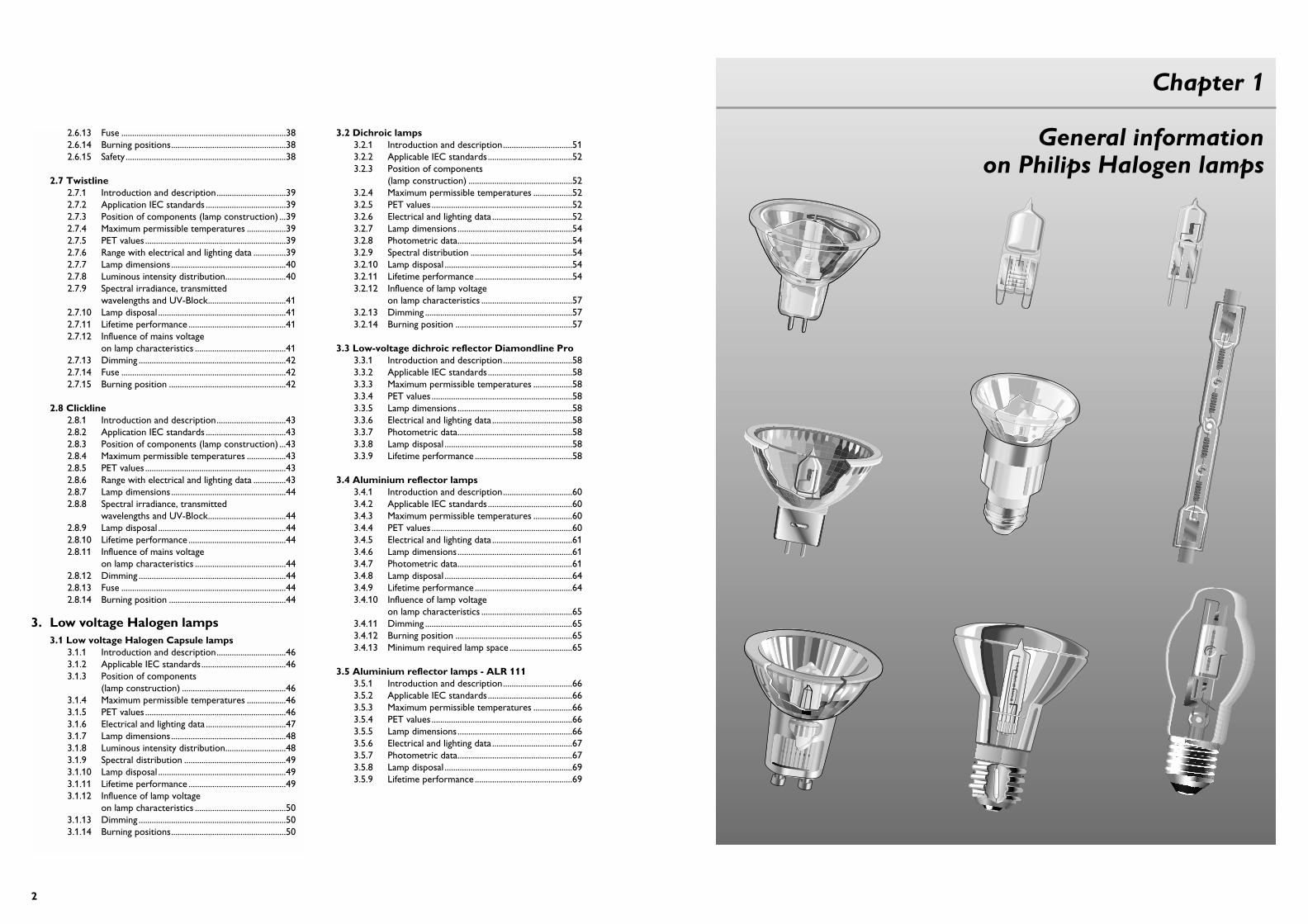
2.6.13 Fuse ............................................................................382.6.14 Burning positions.....................................................382.6.15 Safety ..........................................................................38
2.7 Twistline2.7.1 Introduction and description................................392.7.2 Application IEC standards .....................................392.7.3 Position of components (lamp construction) ...392.7.4 Maximum permissible temperatures ..................392.7.5 PET values .................................................................392.7.6 Range with electrical and lighting data ...............392.7.7 Lamp dimensions.....................................................402.7.8 Luminous intensity distribution............................402.7.9 Spectral irradiance, transmitted
wavelengths and UV-Block....................................412.7.10 Lamp disposal ...........................................................412.7.11 Lifetime performance .............................................412.7.12 Influence of mains voltage
on lamp characteristics ..........................................412.7.13 Dimming ....................................................................422.7.14 Fuse ............................................................................422.7.15 Burning position ......................................................42
2.8 Clickline2.8.1 Introduction and description................................432.8.2 Application IEC standards .....................................432.8.3 Position of components (lamp construction) ...432.8.4 Maximum permissible temperatures ..................432.8.5 PET values .................................................................432.8.6 Range with electrical and lighting data ...............432.8.7 Lamp dimensions.....................................................442.8.8 Spectral irradiance, transmitted
wavelengths and UV-Block....................................442.8.9 Lamp disposal ...........................................................442.8.10 Lifetime performance .............................................442.8.11 Influence of mains voltage
on lamp characteristics ..........................................442.8.12 Dimming ....................................................................442.8.13 Fuse ............................................................................442.8.14 Burning position ......................................................44
3. Low voltage Halogen lamps3.1 Low voltage Halogen Capsule lamps
3.1.1 Introduction and description................................463.1.2 Applicable IEC standards.......................................463.1.3 Position of components
(lamp construction) ................................................463.1.4 Maximum permissible temperatures ..................463.1.5 PET values .................................................................463.1.6 Electrical and lighting data .....................................473.1.7 Lamp dimensions.....................................................483.1.8 Luminous intensity distribution............................483.1.9 Spectral distribution ...............................................493.1.10 Lamp disposal ...........................................................493.1.11 Lifetime performance .............................................493.1.12 Influence of lamp voltage
on lamp characteristics ..........................................503.1.13 Dimming ....................................................................503.1.14 Burning positions.....................................................50
3.2 Dichroic lamps3.2.1 Introduction and description................................513.2.2 Applicable IEC standards.......................................523.2.3 Position of components
(lamp construction) ................................................523.2.4 Maximum permissible temperatures ..................523.2.5 PET values .................................................................523.2.6 Electrical and lighting data .....................................523.2.7 Lamp dimensions.....................................................543.2.8 Photometric data.....................................................543.2.9 Spectral distribution ...............................................543.2.10 Lamp disposal ...........................................................543.2.11 Lifetime performance .............................................543.2.12 Influence of lamp voltage
on lamp characteristics ..........................................573.2.13 Dimming ....................................................................573.2.14 Burning position ......................................................57
3.3 Low-voltage dichroic reflector Diamondline Pro3.3.1 Introduction and description................................583.3.2 Applicable IEC standards.......................................583.3.3 Maximum permissible temperatures ..................583.3.4 PET values .................................................................583.3.5 Lamp dimensions.....................................................583.3.6 Electrical and lighting data .....................................583.3.7 Photometric data.....................................................583.3.8 Lamp disposal ...........................................................583.3.9 Lifetime performance .............................................58
3.4 Aluminium reflector lamps3.4.1 Introduction and description................................603.4.2 Applicable IEC standards.......................................603.4.3 Maximum permissible temperatures ..................603.4.4 PET values .................................................................603.4.5 Electrical and lighting data .....................................613.4.6 Lamp dimensions.....................................................613.4.7 Photometric data.....................................................613.4.8 Lamp disposal ...........................................................643.4.9 Lifetime performance .............................................643.4.10 Influence of lamp voltage
on lamp characteristics ..........................................653.4.11 Dimming ....................................................................653.4.12 Burning position ......................................................653.4.13 Minimum required lamp space .............................65
3.5 Aluminium reflector lamps - ALR 1113.5.1 Introduction and description................................663.5.2 Applicable IEC standards.......................................663.5.3 Maximum permissible temperatures ..................663.5.4 PET values .................................................................663.5.5 Lamp dimensions.....................................................663.5.6 Electrical and lighting data .....................................673.5.7 Photometric data.....................................................673.5.8 Lamp disposal ...........................................................693.5.9 Lifetime performance .............................................69
2
Chapter 1
General information on Philips Halogen lamps
54
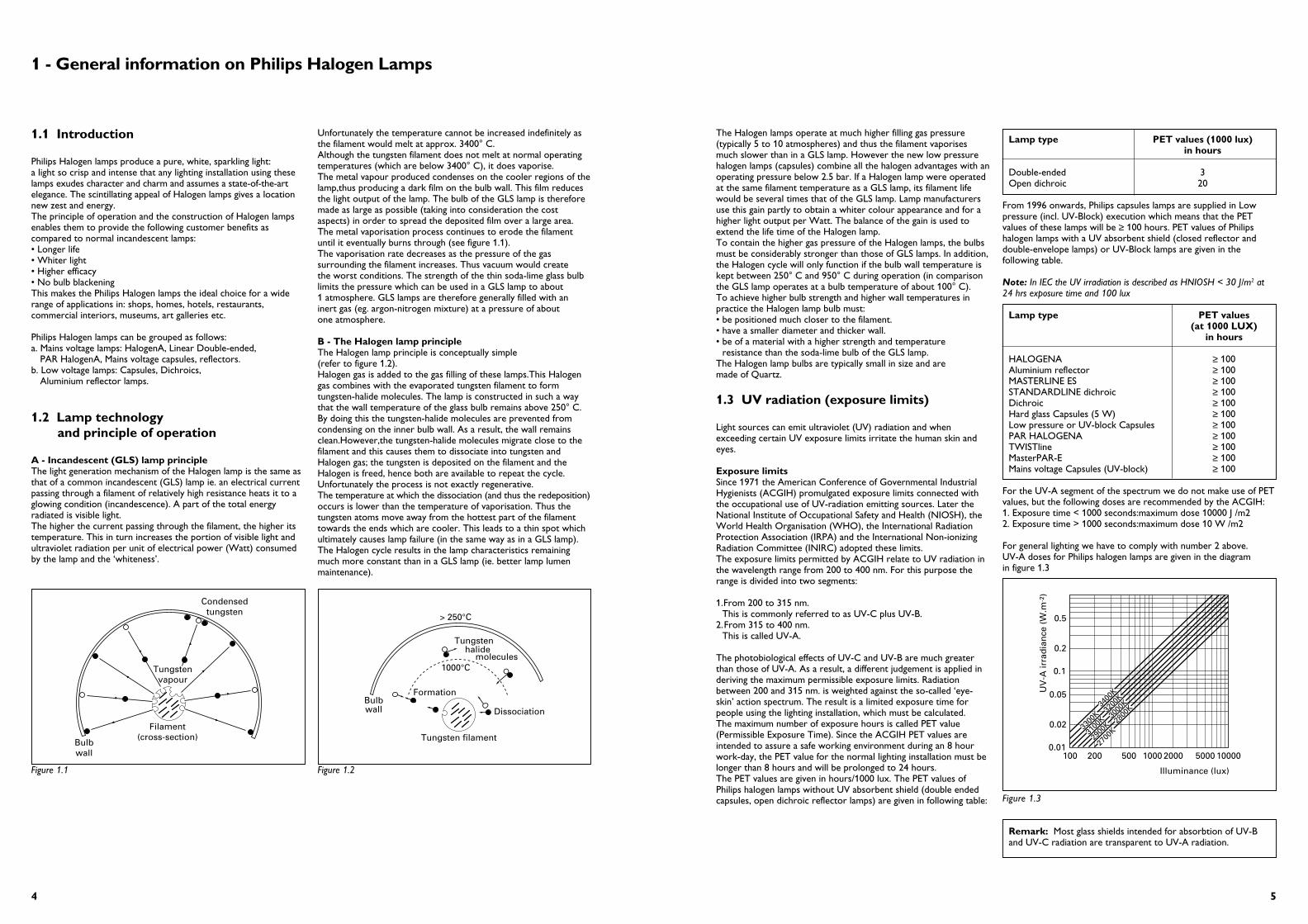
The Halogen lamps operate at much higher filling gas pressure(typically 5 to 10 atmospheres) and thus the filament vaporisesmuch slower than in a GLS lamp. However the new low pressurehalogen lamps (capsules) combine all the halogen advantages with anoperating pressure below 2.5 bar. If a Halogen lamp were operatedat the same filament temperature as a GLS lamp, its filament lifewould be several times that of the GLS lamp. Lamp manufacturersuse this gain partly to obtain a whiter colour appearance and for ahigher light output per Watt. The balance of the gain is used toextend the life time of the Halogen lamp.To contain the higher gas pressure of the Halogen lamps, the bulbsmust be considerably stronger than those of GLS lamps. In addition,the Halogen cycle will only function if the bulb wall temperature iskept between 250° C and 950° C during operation (in comparisonthe GLS lamp operates at a bulb temperature of about 100° C). To achieve higher bulb strength and higher wall temperatures inpractice the Halogen lamp bulb must:• be positioned much closer to the filament.• have a smaller diameter and thicker wall.• be of a material with a higher strength and temperature
resistance than the soda-lime bulb of the GLS lamp. The Halogen lamp bulbs are typically small in size and are made of Quartz.
1.3 UV radiation (exposure limits)
Light sources can emit ultraviolet (UV) radiation and whenexceeding certain UV exposure limits irritate the human skin andeyes.
Exposure limits Since 1971 the American Conference of Governmental IndustrialHygienists (ACGIH) promulgated exposure limits connected withthe occupational use of UV-radiation emitting sources. Later theNational Institute of Occupational Safety and Health (NIOSH), theWorld Health Organisation (WHO), the International RadiationProtection Association (IRPA) and the International Non-ionizingRadiation Committee (INIRC) adopted these limits.The exposure limits permitted by ACGIH relate to UV radiation inthe wavelength range from 200 to 400 nm. For this purpose therange is divided into two segments:
1.From 200 to 315 nm. This is commonly referred to as UV-C plus UV-B.
2.From 315 to 400 nm.This is called UV-A.
The photobiological effects of UV-C and UV-B are much greaterthan those of UV-A. As a result, a different judgement is applied inderiving the maximum permissible exposure limits. Radiationbetween 200 and 315 nm. is weighted against the so-called ‘eye-skin’ action spectrum. The result is a limited exposure time forpeople using the lighting installation, which must be calculated. The maximum number of exposure hours is called PET value(Permissible Exposure Time). Since the ACGIH PET values areintended to assure a safe working environment during an 8 hourwork-day, the PET value for the normal lighting installation must belonger than 8 hours and will be prolonged to 24 hours.The PET values are given in hours/1000 lux. The PET values ofPhilips halogen lamps without UV absorbent shield (double endedcapsules, open dichroic reflector lamps) are given in following table:
Lamp type PET values (1000 lux) in hours
Double-ended 3Open dichroic 20
From 1996 onwards, Philips capsules lamps are supplied in Lowpressure (incl. UV-Block) execution which means that the PETvalues of these lamps will be ≥ 100 hours. PET values of Philipshalogen lamps with a UV absorbent shield (closed reflector anddouble-envelope lamps) or UV-Block lamps are given in thefollowing table.
Note: In IEC the UV irradiation is described as HNIOSH < 30 J/m2 at24 hrs exposure time and 100 lux
Lamp type PET values(at 1000 LUX)
in hours
HALOGENA ≥ 100Aluminium reflector ≥ 100MASTERLINE ES ≥ 100STANDARDLINE dichroic ≥ 100Dichroic ≥ 100Hard glass Capsules (5 W) ≥ 100Low pressure or UV-block Capsules ≥ 100PAR HALOGENA ≥ 100TWISTline ≥ 100MasterPAR-E ≥ 100Mains voltage Capsules (UV-block) ≥ 100
For the UV-A segment of the spectrum we do not make use of PETvalues, but the following doses are recommended by the ACGIH:1. Exposure time < 1000 seconds:maximum dose 10000 J /m22. Exposure time > 1000 seconds:maximum dose 10 W /m2
For general lighting we have to comply with number 2 above.UV-A doses for Philips halogen lamps are given in the diagram in figure 1.3
Remark: Most glass shields intended for absorbtion of UV-Band UV-C radiation are transparent to UV-A radiation.
0.01
0.02
0.05
0.1
0.2
0.5
UV
-A ir
rad
ian
ce (
W.m
-2)
100 200 500 20001000 5000 10000
Illuminance (lux)
2700
K28
00K
2900
K30
00K
3100
K32
00K
3300
K34
00K
Figure 1.3
1 - General information on Philips Halogen Lamps
Unfortunately the temperature cannot be increased indefinitely asthe filament would melt at approx. 3400° C.Although the tungsten filament does not melt at normal operatingtemperatures (which are below 3400° C), it does vaporise. The metal vapour produced condenses on the cooler regions of thelamp,thus producing a dark film on the bulb wall. This film reducesthe light output of the lamp. The bulb of the GLS lamp is thereforemade as large as possible (taking into consideration the costaspects) in order to spread the deposited film over a large area.The metal vaporisation process continues to erode the filamentuntil it eventually burns through (see figure 1.1).The vaporisation rate decreases as the pressure of the gassurrounding the filament increases. Thus vacuum would create the worst conditions. The strength of the thin soda-lime glass bulblimits the pressure which can be used in a GLS lamp to about 1 atmosphere. GLS lamps are therefore generally filled with aninert gas (eg. argon-nitrogen mixture) at a pressure of about one atmosphere.
B - The Halogen lamp principleThe Halogen lamp principle is conceptually simple (refer to figure 1.2).Halogen gas is added to the gas filling of these lamps.This Halogengas combines with the evaporated tungsten filament to formtungsten-halide molecules. The lamp is constructed in such a waythat the wall temperature of the glass bulb remains above 250° C. By doing this the tungsten-halide molecules are prevented fromcondensing on the inner bulb wall. As a result, the wall remainsclean.However,the tungsten-halide molecules migrate close to thefilament and this causes them to dissociate into tungsten andHalogen gas; the tungsten is deposited on the filament and theHalogen is freed, hence both are available to repeat the cycle.Unfortunately the process is not exactly regenerative. The temperature at which the dissociation (and thus the redeposition)occurs is lower than the temperature of vaporisation. Thus thetungsten atoms move away from the hottest part of the filamenttowards the ends which are cooler. This leads to a thin spot whichultimately causes lamp failure (in the same way as in a GLS lamp).The Halogen cycle results in the lamp characteristics remainingmuch more constant than in a GLS lamp (ie. better lamp lumenmaintenance).
1.1 Introduction
Philips Halogen lamps produce a pure, white, sparkling light: a light so crisp and intense that any lighting installation using theselamps exudes character and charm and assumes a state-of-the-artelegance. The scintillating appeal of Halogen lamps gives a locationnew zest and energy.The principle of operation and the construction of Halogen lampsenables them to provide the following customer benefits ascompared to normal incandescent lamps:• Longer life• Whiter light• Higher efficacy• No bulb blackeningThis makes the Philips Halogen lamps the ideal choice for a widerange of applications in: shops, homes, hotels, restaurants,commercial interiors, museums, art galleries etc.
Philips Halogen lamps can be grouped as follows:a. Mains voltage lamps: HalogenA, Linear Double-ended,
PAR HalogenA, Mains voltage capsules, reflectors.b. Low voltage lamps: Capsules, Dichroics,
Aluminium reflector lamps.
1.2 Lamp technology and principle of operation
A - Incandescent (GLS) lamp principleThe light generation mechanism of the Halogen lamp is the same asthat of a common incandescent (GLS) lamp ie. an electrical currentpassing through a filament of relatively high resistance heats it to aglowing condition (incandescence). A part of the total energyradiated is visible light.The higher the current passing through the filament, the higher itstemperature. This in turn increases the portion of visible light andultraviolet radiation per unit of electrical power (Watt) consumedby the lamp and the ‘whiteness’.
Tungstenvapour
Bulbwall
Condensedtungsten
Filament(cross-section)
1000°C
> 250°C
Formation
DissociationBulbwall
Tungstenhalide
molecules
Tungsten filament
Figure 1.1 Figure 1.2

76
B - Lamps for consumer purposes without integral outer envelope should normally be used in shielded luminaires, as recommended by IEC.
PICTURE DESCRIPTION INSTRUCTIONS
Brilliantline PRO No precautionsStandard dichroic necessary
Low voltage aluminium refl. No precautionslamp with front glass necessary”Aluminium Reflector“
Mains voltage No precautionsreflector lamp necessary”PAR HalogenA”
Mains voltage No precautionsreflector lamp necessary”Twistline”
Mains voltage No precautionsreflector lamp necessary”MasterPAR-E”
Mains voltage double No precautionsenvelope lamp necessary”HalogenA”
Mains voltage capsule No precautions“Clickline” necessary
Safety requirements
A - Lamps for consumer purposes which have an integral outer envelope do not require special precautions:
Figure 1.4
Figure 1.5
PICTURE DESCRIPTION INSTRUCTIONS
Low voltage dichroiclamp ”open dichroic”
Should be usedin a luminaire with protective front glass
Low pressure capsule No precautions necessary
UV-Block capsules Should be usedin a luminaire withprotective front glass
Mains voltage B 15dsingle ended lamp(UV-Block)
Should be usedin a luminaire with protection against touching of the lamp
Mains voltage double endedlinear lamp”Plusline/Linear“
Should be used in a luminaire with front glass
Low voltage dichroic No precautionslamp with front glass necessary”MASTERline ES

Chapter 2
Mains voltage Halogen lamps
8
1.4 Dimming of Halogen lamps
When halogen lamps are dimmed, the power in the lamp isreduced. At a certain point the power reaches a level where the halogen cycle no longer works. This is due to the fact that the temperature inside the lamp bulb falls below the required level.The evaporation of the filament goes on nevertheless, at a lowerrate due to the reduced current. This will now lead to blackeningand temperature differences on the bulb wall just like in normalGLS lamps.For that reason, lamp producers advise not to keep the lamps in adimmed condition all the time. Frequent operation of the lamps atfull power is advisable to avoid this blackening of the bulb.Dimming low-voltage halogen lamps is not a straightforward matter,due to the presence of a transformer. Traditionally, in many caseswall dimmers are used to dim the lighting level of incandescentlamps. With one restriction this kind of dimmer can be used forconventional magnetic transformers, the restriction being that aburning lamp must be present! If this is not the case, thetransformer will heat up to very high temperatures. This can resultin a blown fuse, if present, or melting or damaging of the luminaire.Electronic transformers need dimmers capable of handlingcapacitive loads: due to the presence of the EMI filter the dimmerload changes from inductive (for conventional/magnetictransformers) to capacitive (for electronic transformers). A conventional dimmer intended for use with incandescentlamp/conventional transformers cannot work properly with thiscapacitive load. Phenomena like hum, light flicker, sudden rise oflighting level while dimming, or even destruction of dimmer and/orelectronic halogen tranformers can happen. For this reason specialphase-cut dimmers are required to regulate the lighting level ofelectronic halogen transformers. The dimmer has to be connectedin the phase-line. The own power consumption of the dimmercauses a reduction in the maximum achievable brightness.
1.5 Thermocouple lamps
Philips lamps equipped with thermocouples can be used during:• design• testing• selection• evaluation of a luminaire for measuring temperatures.
Philips can provide thermocouple lamps in accordance with IEC 682 of:• capsules• reflector lamps• flood lampsThese thermocouple lamps can be made available to OriginalEquipment Manufacturers against specific request.
Temperature measurements are important because:• excess pinch (base) temperatures cause premature lamp failures.• pinch temperature is a complex function of luminaire design,
construction, burning position and ventilation.• trend towards compact luminaires increases the technical
challenge for OEM’s and lamp specifiers.
1.6 Environmental aspects
A - Energy consumptionLight is largely a matter of energy; product life cycle analysis showthat approximately 90 % of the effect of light sources on theenvironment is represented by their energy consumption duringusage. Materials, production process, and disposal at the end of lifeare responsible for only the remaining 10 %. This includes theenergy and materials used during production and the effects ofspent products, the packaging and transportation activities.
B - UV radiation of Halogen lampsThis has been dealt at length earlier under ‘UV RADIATION(EXPOSURE LIMITS)’.
C - Lamp disposalNo separate collection is needed as Halogen light sources do notcontain any materials that have an impact on the environment. These lamps contain very small quantities of materials such as leadand antimony which are embedded in some glass parts namelytubes, reflectors and solder. The impact on the environment ofthese is therefore negligible.
D - Philips commitment to the environmentPhilips lighting has committed itself to the International Chamber ofCommerce (ICC) business charter on the environment. This policymeans that the company is striving for permanent improvementsand for minimising the application of environmentally sensitivesubstances, with the aim of the eventual elimination of all suchsubstances. Concrete programmes are in progress to achieve thisobjective.
1.7 Energy Efficiency Label
This label is the result of a European Commision directive 92/75/EECrelating to electricity used by household electric lamps supplieddirectly from the mains. This does not include the following lamps:those with Luminous Flux > 6500Lm, Those with input power < 4watts, or reflector lamps. An example of the label is shown below.
There is a formula to calculate which classification a lamp falls into,shown below:
When not Class A, a reference wattage WR isCalculated: WR = 0.88 √Ø + 0.049 Ø(when Ø is > 34 lumens )where Ø is the lumen output of the lamp.
An energy efficiency index E1 is then set as:
E1 = W / WR
Where W is the power input into the lamp inWatts
Energy Efficiency class Energy efficiency index E1
B E1 < 60 %C 60 % ≤ E1 ≥ 80 %D 80 % ≤ E1 ≥ 95 %E 95 % ≤ E1 ≥ 110 %F 110 % ≤ E1 ≥ 130 %G E1 ≥ 130 %
Energiae * ** ***
****
**
y
A
B
C
E
D
F
G
E
Energiae * ** ***
****
*** ** ***
****
*** ** ***
****
**
y
A
B
C
E
D
F
G
EE

1110
2.1.3 Position of components(lamp construction)
Figure 2.1 shows the construction details and components of aHalogenA BTT lamp:
2.1.4 Lamp cap temperature rise
IEC 432-1 and 432-2 give the maximum allowable cap temperaturerise for various lamp wattages and classes.
Standards for caps E27: 60 W ∆Ts 25 max. 120° K100/150 W ∆Ts 25 max. 130° K
E14: 40 W ∆Ts 25 max. 130° K60 W ∆Ts 25 max. 140° K
B15d: 40 W ∆Ts 25 max. 135° K60 W ∆Ts 25 max. 145° K
Note:1. 100 W with E14 are not yet specified in IEC 432-1 (IEC proposal
for the same is however under preparation). However the values forthese Philips lamps are even below the max. temperatures for 60 Wversions given in the specifications.
2. E11 lamps are specified in IEC 357 and 61-1 although an exception is made for Europe.”Lamps with caps E12, E17, E26/24,E26/25 are excluded from this European standard” (Reason: Theselamp/holder fit system do not comply with the European safetyrequirements).
2.1.5 PET values
For the PET values for all Philips Halogen lamps refer to chapter 1.3in the brochure.
Spectral distributionAll HalogenA lamps have an integral outer envelope and thus theUV radiation from these lamps is of no importance. A typicalspectral power distribution diagram is given in figure 2.2.
300 400 500 600 700
100
300
500
Wavelength nm
200
400
0
µW p
er 5
nm
Figure 2.2
1
234
678
910
11
12
13
5
1 - Lead-in wire2 - Pinch lead3 - Tube4 - Coil5 - Gas filling6 - Wire connect7 - Bulb
8 - Wing9 - Stem tube
10 - Exhaust Tube11 - Capping cement12 - Cap13 - Solder
Figure 2.1
2.1 - HalogenA lamps
2.1.1 Introduction and description
The double-envelope HalogenA lamps contain a compact quartzburner with a linear tungsten filament and internal fuses. The filament is fixed in the quartz tube by means of indents in thetube. The tube is placed axially in a single-ended normal glass outerenvelope which is filled with a mixture of inert gases (to avoidcorrosion) and equipped with a standard GLS lamp cap. Unlikeother Halogen lamps, the HalogenA lamps can be touched withbare hands. The outer envelope minimizes UV radiation andtherefore a glass cover on the luminaire is not necessary.
Benefits Features
Fully interchangeable in GLS • same lamp caps as GLS lampslamp sockets of same wattage • no transformer requiredratings (can be used to • universal burning positionupgrade existing GLS points) • comparable lamp dimensions
• outer lamp envelope temp. comparable with GLS lamps
• lamp cap temperatures comparable to GLS lamps
No waiting for desired lighting • immediate start and level or colour temperature-restart
Lighting can be adapted to • dimmabledesired level and ‘mood’
User security • two arc preventing fuses and an electrical fuse
• outer glass envelope results in significant UV levels and makes the lamp easily manageable
Besides the above,the HalogenA lamps offer all the user benefits ofHalogen lamps, namely:
Upto 15 % more light • higher luminous efficacyPure bright light • colour temp. 2900° KReproduces colours most • Ra=100realisticallyLonger lamp life and thus • 2000 burning hoursless lamp replacementConstant light output over life • no bulb blackening
The HalogenA lamps offer the following benefits to the luminairemanufacturers:
Benefits Features
A business opportunity which • to replace a wide range upgrade allows distinguishing of GLS and retrofit lamps
Opportunity to design • lamps are retrofit inluminaires with user friendly GLS luminaires and and efficient lamps satisfy customer needs
for a variety ofapplications
Lower integral costs • no front glass required• low lamp cap temperatures• no extra fuse required
in luminaire • uses cheap, easy to source
lamp-holders• no trafo required
ApplicationsThe HalogenA lamps are ideally suited for a wide variety ofapplications, some of which are given below:
1. HalogenA BTT lamps : • task lighting (reading and free standing luminaires)• general lighting (wall washers and uplighters)The small HalogenA BTT are primarily for use in living rooms and bedrooms in both suspended and wall mounted luminaires.
2. HalogenA-T lamps (T20 and 32) : the slim design of these lamps makes them suitable for shops, hotels, restaurants, offices and homes in:• task lighting (reading and free standing luminaires)• general lighting (wall washers and uplighters)• accent lighting (spots)• decorative lighting (small luminaires and furniture)
3. HalogenA Candle lamps : the special shape of these lamps is ideal for decorative applications such as chandeliers (both suspended and wall mounted)
4. HalogenA Globe lamps: suitable for hotels, restaurants (entrance halls and passages, above tables), bars, public halls, shops and for tasklighting in homes.
5. HalogenA Reflector lamps: suitable for homes, hotels, restaurants, bars, shops for down- and accentlighting.
2.1.2 Applicable standards
The applicable standards for HalogenA lamps are :IEC 432-1 and 432-2
1312
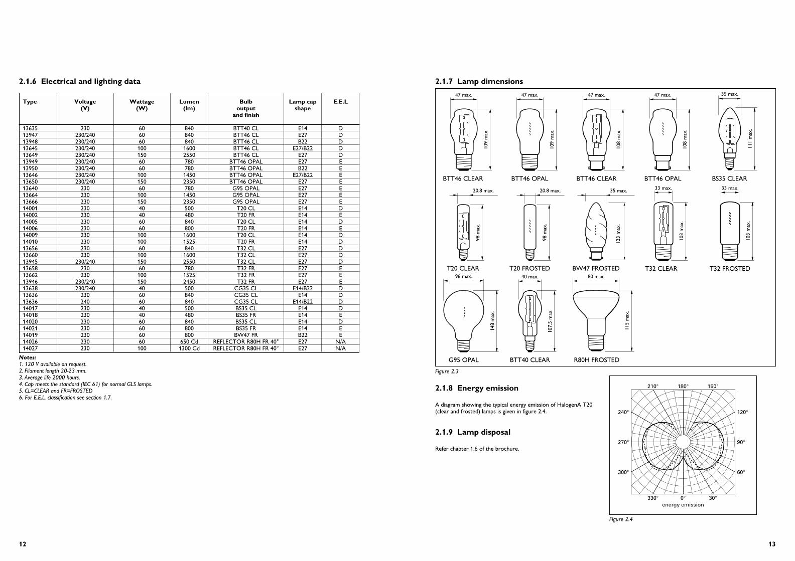
2.1.7 Lamp dimensions
2.1.8 Energy emission
A diagram showing the typical energy emission of HalogenA T20(clear and frosted) lamps is given in figure 2.4.
2.1.9 Lamp disposal
Refer chapter 1.6 of the brochure.
47 max.
109
max
.
47 max.
109
max
.
47 max.
108
max
.
47 max.
108
max
.
20.8 max.
98 m
ax.
20.8 max.
98 m
ax.
35 max. 33 max.
103
max
.
33 max.
103
max
.
96 max.
148
max
.
40 max.
107.
5 m
ax.
BTT46 CLEAR BTT46 OPAL
G95 OPAL BTT40 CLEAR
BTT46 CLEAR BTT46 OPAL BS35 CLEAR
BW47 FROSTED
R80H FROSTED
T20 CLEAR T20 FROSTED T32 CLEAR T32 FROSTED
35 max.
111
max
.
123
max
.
80 max.
115
max
.
energy emission330° 0° 30°
90°
60°
120°
210° 180° 150°
270°
300°
240°
Figure 2.3
Figure 2.4
Notes:1. 120 V available on request.2. Filament length 20-23 mm.3. Average life 2000 hours.4. Cap meets the standard (IEC 61) for normal GLS lamps.5. CL=CLEAR and FR=FROSTED6. For E.E.L. classification see section 1.7.
Type Voltage Wattage Lumen Bulb Lamp cap E.E.L(V) (W) (lm) output shape
and finish
13635 230 60 840 BTT40 CL E14 D13947 230/240 60 840 BTT46 CL E27 D13948 230/240 60 840 BTT46 CL B22 D13645 230/240 100 1600 BTT46 CL E27/B22 D13649 230/240 150 2550 BTT46 CL E27 D13949 230/240 60 780 BTT46 OPAL E27 E13950 230/240 60 780 BTT46 OPAL B22 E13646 230/240 100 1450 BTT46 OPAL E27/B22 E13650 230/240 150 2350 BTT46 OPAL E27 E13640 230 60 780 G95 OPAL E27 E13664 230 100 1450 G95 OPAL E27 E13666 230 150 2350 G95 OPAL E27 E14001 230 40 500 T20 CL E14 D14002 230 40 480 T20 FR E14 E14005 230 60 840 T20 CL E14 D14006 230 60 800 T20 FR E14 E14009 230 100 1600 T20 CL E14 D14010 230 100 1525 T20 FR E14 D13656 230 60 840 T32 CL E27 D13660 230 100 1600 T32 CL E27 D13945 230/240 150 2550 T32 CL E27 D13658 230 60 780 T32 FR E27 E13662 230 100 1525 T32 FR E27 E13946 230/240 150 2450 T32 FR E27 E13638 230/240 40 500 CG35 CL E14/B22 D13636 230 60 840 CG35 CL E14 D13636 240 60 840 CG35 CL E14/B22 D14017 230 40 500 BS35 CL E14 D14018 230 40 480 BS35 FR E14 E14020 230 60 840 BS35 CL E14 D14021 230 60 800 BS35 FR E14 E14019 230 60 800 BW47 FR B22 E14026 230 60 650 Cd REFLECTOR R80H FR 40° E27 N/A14027 230 100 1300 Cd REFLECTOR R80H FR 40° E27 N/A
2.1.6 Electrical and lighting data

1514
2.2 - Linear double-ended Halogen lamps
2.2.1 Introduction and description
PLUSlineDouble-ended mains voltage linear Halogen lamps with a coiled-coilfilament and a clear tubular (UV block for small types) quartz bulb.The lamps rated upto 500 W (ie. Compact and Small range) areequipped with two built-in arc preventing fuses. The lamps areshock-resistant and have universal burning positions as they havedouble supports held by indents in the quartz tube. All the lampshave R7s lamp caps except the 2000 W lamps which have Fa4 lampcaps.
LinearDouble-ended mains voltage linear halogen lamp with single-coilfilament and a clear tubular quartz bulb. The lamps are equippedwith R7s lamp cap.
Range PLUSline
Compact (78.3 mm) 60 W 100 W 150 W 200 WSmall (117.6 mm) 150 W 200 W 300 W 500 WLarge (> 186 mm) 750 W 1000 W 500 W 2000 W
Range Linear
Small (117.6 mm) 200 W 300 W 500 W
Benefits of PLUSline lamps
Benefits Features
Upto 15 % more light than • higher luminous efficacystandard linear halogen lamps (coiled-coil filament)
Sparkling,crisp,white light • colour temp. 2900° K
Reproduces colours truly • Ra=100longer lamp life • 2000 burning hours(except
60 W which is 1500 hours)Constant light output • no bulb blackeningover life • shock resistant
• dimples• universal burning position
Suitable for wide range of • diverse wattage rangeapplications • dimmableUser security (Philips patent) • arc preventing fuse
Benefits of Linear
Benefits Features
User security (Philips patent) arc preventing fusesLong lamp life average lamp life of 1500 hrs.Reproduces colours truly excellent colour rendering
(Ra=100)Suitable for a wide range dimmableof applications
Applications of PLUSline lampsPLUSline lamps are ideally suited for a variety of applications such as : Floodlighting, Wallwashing, Uplighting and Tasklighting.
The application areas include both Indoor (Homes, Shops,Museums, Sports halls, Factories etc.) and Outdoor (Sportsgrounds, Car parks, Billboards, Construction sites, security lightingetc.)
Applications of LinearLinear Halogen lamps are ideally suitable for flood-, up-, tasklightingand wall-washing in homes, shops, hotels, restaurants and securitylighting (outdoor)
2.2.2 Applicable IEC standards
The applicable IEC standards for double-ended linear Halogen lamps is: IEC 357, IEC 432.
2.2.3 Position of components (lamp construction)
2.2.4 Maximum permissible temperatures
The maximum permissible temperatures for different parts of the lamp are:
Pinch: 350° CTube: 900° C (minimum 250° C)
Exceeding these temperatures will influence lifetime negatively.
1
2
3
4
5
6
7
Figure 2.8 Linear
1
2
3
4
5
6
7
Figure 2.9 Plusline
2.1.10 Lifetime performance
A - Lifetime: A typical life expectancy curve for Mains voltage Halogen lamps is given in figure 2.5
B - Lamp lumen depreciation: A typical lamp lumen depreciation curve for Mains voltage Halogen lamps is given in figure 2.6
2.1.11 Influence of mains voltage and lamp performance
The graphs in figure 2.7 shows the relationship between lampvoltage and other lamp operating parameters. The curve shows thata 5 % overvoltage reduces the lamp-life by half.
2.1.12 Dimming
All HalogenA lamps can be dimmed, see also chapter 1.4.
2.1.13 Fuse (Philips patent)
The Philips HalogenA lamps are provided with fuse in the lamp capand with arc preventing fuses in the pinch of the burner.Incidentically an arc can occur at the end of life of a lamp. Thesefuses serve to extinguish the arc before the temperature reachesthe critical limit. These fuses are not electrical but work byphysically extinguishing the arc when it reaches them. This designand base fuse is covered by a Philips patent.
2.1.14 Burning positions
All HalogenA lamps have a universal burning position which makesthem suitable for a wide range of applications.
2.1.15 Safety
Since all Philips HalogenA lamps are provided with an integral outerenvelope, these lamps can be used in open luminaires (ie. luminaireswithout outer glass covers). For outdoor applications, waterproofluminaires have to be used.
50
60
70
80
90
100
0 750 1500 2250 3000 3750 4500
Lum
en in
%
Burning hours
Lumen maintenance
Lamp type:Mains voltage Halogen- HALOGENA
double envelope
HalogenA
W
lm/W
lm
W
lm/W
lm
Life
40
60
80
100
120
140
160%
90 95 100 105 110V
Figure 2.6
Figure 2.7
50
60
70
80
90
100
0 750 1500 2250 3000 3750 4500
Su
rviv
als
in %
Burning hours
Life expectancy
Lamp type:Mains voltage Halogen- HALOGENA
double envelope
HalogenA
Figure 2.5
1 Contact2 Pinch lead3 Tube4 Coil
5 Gas filling6 Cement7 Cap

1716
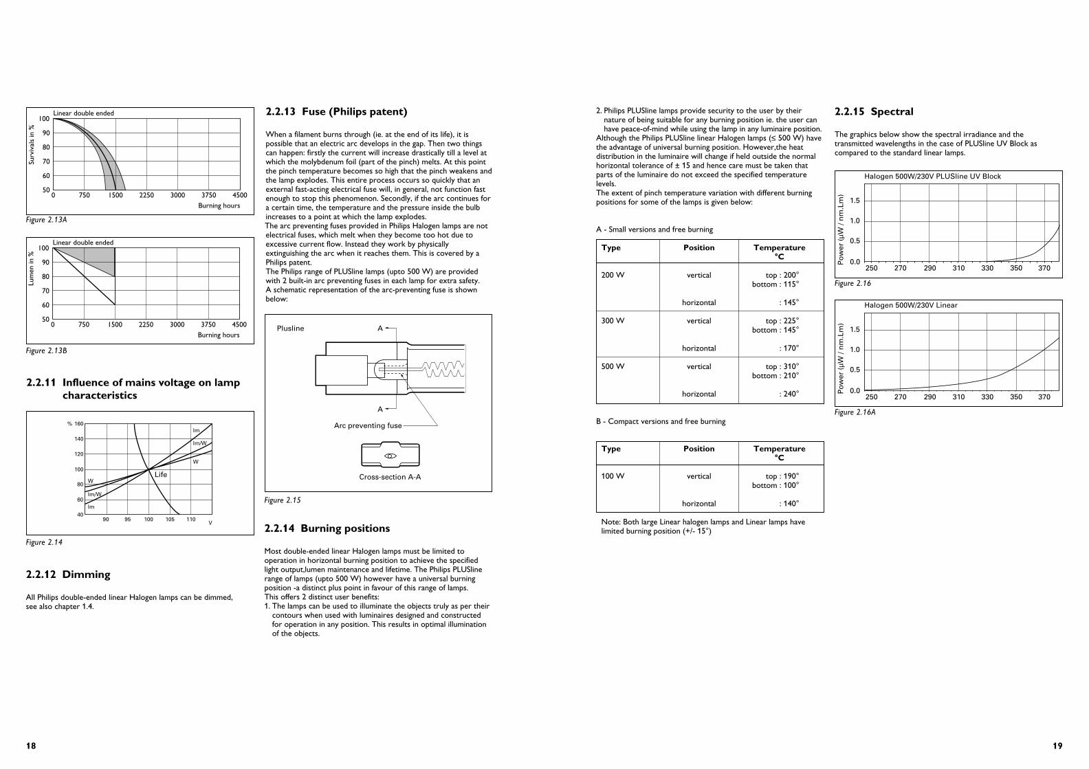
2.2.10 Lifetime performance
A - LifetimeTypical life expectancy curves for double-ended linear Halogenlamps is given in figure 2.12 below (2000 h. lamps):
B - Lamp lumen depreciationTypical lamp lumen depreciation curves for double-ended linearHalogen lamps is shown in figure 2.13 below (2000 h. lamps):
2.2.7 Lamp dimensions
2.2.8 Luminous intensity distribution
The luminous intensities distribution for a 300 W Plusline double-ended linear Halogen lamp is given below:
2.2.9 Lamp disposal
Refer chapter 1.6 in this brochure.
74.9 ± 1.6
78.3 max.
11 max.
114.2 ± 1.6
117.6 max.
11 max.
185.7 ± 1.6
189.1 max.
11 max.
250.7 ± 1.6
254.1 max.
11 max.
322 ± 2.1
334.4 max.
11 max.
Compact Small Large
LargeLarge
050
60
70
80
90
100PLUSline double ended
750 1500 2250 3000 3750 4500
Surv
ival
s in
%
Burning hours
330∞ 0∞ 30∞
90∞
60∞
120∞
210∞ 180∞ 150∞
270∞
300∞
240∞
Figure 2.10
Figure 2.12
Figure 2.11
050
60
70
80
90
100PLUSline double ended
750 1500 2250 3000 3750 4500
Lum
en in
%
Burning hours
Figure 2.13
2.2.6 Electrical and lighting data
The details for the 230/240 V PLUSline lamps are given below:
Notes:1. Voltage: 230 V, 240 V (120 V on request)2. Average life: 2000 hours3. Average life 60 W 1500 hours
The details for the 230/240 V linear lamps are given below:
Notes:1. Voltage: 230 V, 240 V (120 V on request)2. Average life: 2000 hours3. Average life 60 W 1500 hours
2.2.5 PET values
Refer chapter 1.3 of the brochure.
Type Wattage Luminous flux Lamp cap Filament length E.E.L.(W) (lm) (mm)
60T3Q/CL/CP 60 810 R7s-15 28 D100T3Q/CL/CP 100 1550 R7s-15 28 D150T3Q/CL/CP 150 2550 R7s-15 28 D200T3Q/CL/CP 200 3400 R7s-15 28 D150T3Q/CL/P 150 2250 R7s-15 62 E200T3Q/CL/P 200 3520 R7s-15 62 D300T3Q/CL/P 300 5600 R7s-15 62 D500T3Q/CL/P 500 9900 R7s-15 62 N/A750T3Q/CL/P 750 16900 R7s-15 124 N/A1000T3Q/CL/P 1000 24200 R7s-15 124 N/A1500T3Q/CL/P 1500 36300 R7s-15 174 N/A2000T3Q/CL/P 2000 48400 Fa4 207 N/A
Type Wattage Luminous flux Lamp cap Filament length(W) (lm) (mm)
200T3Q/CL 200 2820 R7s 1500300T3Q/CL 300 4480 R7s 1500500T3Q/CL 500 7920 R7s 1500
{Plus-line }N/A
1918
2. Philips PLUSline lamps provide security to the user by their nature of being suitable for any burning position ie. the user can have peace-of-mind while using the lamp in any luminaire position.
Although the Philips PLUSline linear Halogen lamps (≤ 500 W) havethe advantage of universal burning position. However,the heatdistribution in the luminaire will change if held outside the normalhorizontal tolerance of ± 15 and hence care must be taken thatparts of the luminaire do not exceed the specified temperaturelevels. The extent of pinch temperature variation with different burning positions for some of the lamps is given below:
A - Small versions and free burning
Type Position Temperature°C
200 W vertical top : 200°bottom : 115°
horizontal : 145°
300 W vertical top : 225°bottom : 145°
horizontal : 170°
500 W vertical top : 310°bottom : 210°
horizontal : 240°
B - Compact versions and free burning
Type Position Temperature°C
100 W vertical top : 190°bottom : 100°
horizontal : 140°
Note: Both large Linear halogen lamps and Linear lamps havelimited burning position (+/- 15°)
2.2.15 Spectral
The graphics below show the spectral irradiance and thetransmitted wavelengths in the case of PLUSline UV Block ascompared to the standard linear lamps.
250 270 290 310 330 370
0.5
1.5
Halogen 500W/230V PLUSline UV Block
1.0
0.0Po
wer
(µW
/ n
m.L
m)
350
Figure 2.16
250 270 290 310 330 370
0.5
1.5
Halogen 500W/230V Linear
1.0
0.0Po
wer
(µW
/ n
m.L
m)
350
Figure 2.16A
2.2.11 Influence of mains voltage on lampcharacteristics
2.2.12 Dimming
All Philips double-ended linear Halogen lamps can be dimmed,see also chapter 1.4.
2.2.13 Fuse (Philips patent)
When a filament burns through (ie. at the end of its life), it ispossible that an electric arc develops in the gap. Then two thingscan happen: firstly the current will increase drastically till a level atwhich the molybdenum foil (part of the pinch) melts. At this pointthe pinch temperature becomes so high that the pinch weakens andthe lamp explodes. This entire process occurs so quickly that anexternal fast-acting electrical fuse will, in general, not function fastenough to stop this phenomenon. Secondly, if the arc continues fora certain time, the temperature and the pressure inside the bulbincreases to a point at which the lamp explodes.The arc preventing fuses provided in Philips Halogen lamps are notelectrical fuses, which melt when they become too hot due toexcessive current flow. Instead they work by physicallyextinguishing the arc when it reaches them. This is covered by aPhilips patent.The Philips range of PLUSline lamps (upto 500 W) are providedwith 2 built-in arc preventing fuses in each lamp for extra safety.A schematic representation of the arc-preventing fuse is shownbelow:
2.2.14 Burning positions
Most double-ended linear Halogen lamps must be limited tooperation in horizontal burning position to achieve the specifiedlight output,lumen maintenance and lifetime. The Philips PLUSlinerange of lamps (upto 500 W) however have a universal burningposition -a distinct plus point in favour of this range of lamps. This offers 2 distinct user benefits:1. The lamps can be used to illuminate the objects truly as per their
contours when used with luminaires designed and constructed for operation in any position. This results in optimal illumination of the objects.
W
lm/W
lm
W
lm/W
lm
Life
40
60
80
100
120
140
160%
90 95 100 105 110V
Figure 2.14
050
60
70
80
90
100Linear double ended
750 1500 2250 3000 3750 4500
Surv
ival
s in
%
Burning hours
050
60
70
80
90
100Linear double ended
750 1500 2250 3000 3750 4500
Lum
en in
%
Burning hours
Figure 2.13A
Figure 2.13B
A
Arc preventing fuse
Plusline
Cross-section A-A
A
Figure 2.15

2120
2.3.6 Range with electrical and lighting data
The mains voltage Halogen capsules are available in 75 W, 100 Wand 150 W in both clear and frosted versions, the details of theselamps are given below:
Type Wattage Voltage Luminous Finish Average(W) (V) Flux(lm) life(h)
12120W 75 230 975 clear 200012123W 75 230 910 frosted 200012119W 100 230 1400 clear 200012122W 100 230 1300 frosted 200012121W 150 230 1900 frosted 2000
Notes:1. All lamps have B15d caps in accordance with IEC 61-12. Colour temperature of the lamps is 2900 K
2.3.7 Lamp dimensions
2.3.8 Luminous intensity distribution
The typical luminous intensity distribution of a 230 V/75 W Mainsvoltage capsule is given in figure 2.20
2.3.9 Lamp disposal
Refer chapter 1.6 of this brochure.
2.3.10 Lifetime performance
A - LifetimeThe Life expectancy of the mains voltage capsules is givenin the curve in figure 2.21
B - Lumen maintenance
15.5 max.
55±
3
86 m
ax.
75 W100 W150 W
050
60
70
80
90
100MV capsules
750 1500 2250 3000 3750 4500
Surv
ival
s in
%
Burning hours
050
60
70
80
90
100MV capsules
750 1500 2250 3000 3750 4500
Lum
en in
%
Burning hours
(candela / 1000 lumen)330° 0° 30°
90°
60°
120°
210° 180° 150°
270°
300°
240°
Figure 2.19
Figure 2.21
Figure 2.22
Figure 2.20
2.3 - Mains voltage capsules
2.3.1 Introduction and description
A range of mains voltage Halogen capsules available in clear/frostedwith UV Block versions having B15d bayonet caps.
Features and benefits
Benefits Features
Upto 15 % more light • higher luminous efficacythan GLS lamps
Pure bright light • colour temp. 2900° K
Excellent colour rendition • Ra=100
Long lamp life • upto 2000 burning hours
Constant light output over life • no end blackening
Ease of installation • no transformer required
Economical source for small, • compact, mains voltage light-weight luminaires Halogen lamp
Ideal for a wide variety of • choice of lamp wattagesapplications • clear and frosted versions
• universal burning position
Safety base • fuse incorporated in lamp • insignificant UV radiation due
to UV Block Quartz glass
ApplicationsMains voltage Halogen capsules are suitable for a variety ofapplications where high intensities are required from compactHalogen lamps with economical light weight luminaires. These include Accent/spot lighting for small objects and shop-windows security lighting, garden and park lighting, building-sitefloodlighting etc.
2.3.2 Applicable IEC standards
IEC 432-1IEC 432-2
2.3.3 Position of components (lamp construction)
2.3.4 Maximum permissible temperature rise
The maximum permissible temperature rise for these lamps are :Bulb : 900° C (minimum 250° C)Pinch : 350° C
2.3.5 PET values
Refer chapter 1.3 of this brochure.
Spectral distributionThe curve below shows the absolute flux measurements for a 230 V 100 W Mains voltage capsule and clearly shows theinsignificant levels of UV radiation from these lamps:
Filament
UV-block quartz
Pinch lead
Ceramic
B15d lamp cap
300 400 500 600 700
100
300
500
Wavelength nm
200
400
0
µW p
er 5
nm
Figure 2.18
Figure 2.17
2322
2.4 - PAR HalogenA lamps
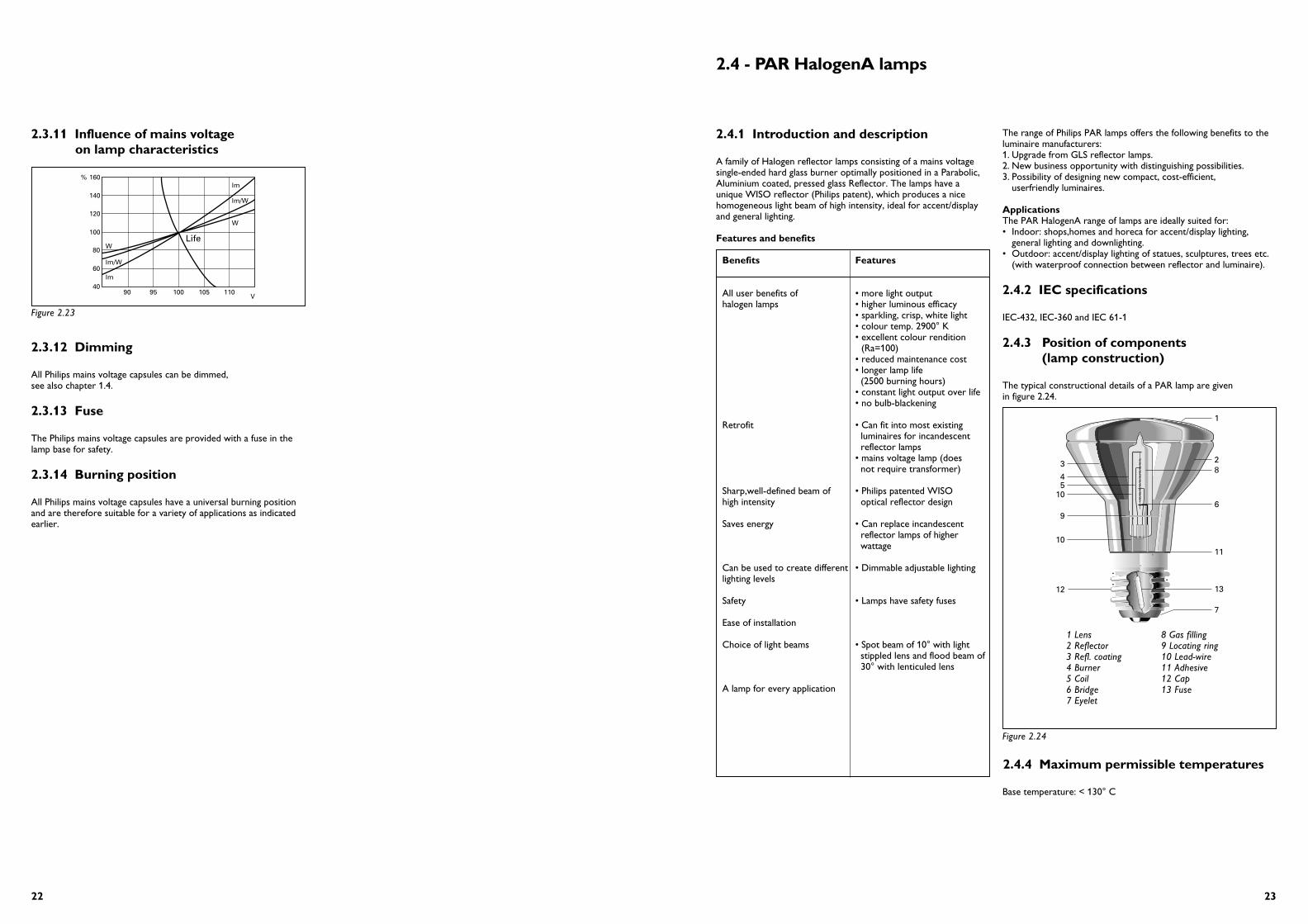
2.4.1 Introduction and description
A family of Halogen reflector lamps consisting of a mains voltagesingle-ended hard glass burner optimally positioned in a Parabolic,Aluminium coated, pressed glass Reflector. The lamps have a unique WISO reflector (Philips patent), which produces a nicehomogeneous light beam of high intensity, ideal for accent/displayand general lighting.
Features and benefits
Benefits Features
All user benefits of • more light outputhalogen lamps • higher luminous efficacy
• sparkling, crisp, white light• colour temp. 2900° K• excellent colour rendition
(Ra=100)• reduced maintenance cost• longer lamp life
(2500 burning hours)• constant light output over life• no bulb-blackening
Retrofit • Can fit into most existingluminaires for incandescent reflector lamps
• mains voltage lamp (doesnot require transformer)
Sharp,well-defined beam of • Philips patented WISOhigh intensity optical reflector design
Saves energy • Can replace incandescentreflector lamps of higherwattage
Can be used to create different • Dimmable adjustable lightinglighting levels
Safety • Lamps have safety fuses
Ease of installation
Choice of light beams • Spot beam of 10° with light stippled lens and flood beam of 30° with lenticuled lens
A lamp for every application
The range of Philips PAR lamps offers the following benefits to theluminaire manufacturers:1. Upgrade from GLS reflector lamps. 2. New business opportunity with distinguishing possibilities.3. Possibility of designing new compact, cost-efficient,
userfriendly luminaires.
ApplicationsThe PAR HalogenA range of lamps are ideally suited for:• Indoor: shops,homes and horeca for accent/display lighting,
general lighting and downlighting.• Outdoor: accent/display lighting of statues, sculptures, trees etc.
(with waterproof connection between reflector and luminaire).
2.4.2 IEC specifications
IEC-432, IEC-360 and IEC 61-1
2.4.3 Position of components(lamp construction)
The typical constructional details of a PAR lamp are given in figure 2.24.
2.4.4 Maximum permissible temperatures
Base temperature: < 130° C
1
23
45
6
7
11
8
10
9
10
1312
Figure 2.24
1 Lens2 Reflector3 Refl. coating4 Burner5 Coil6 Bridge7 Eyelet
8 Gas filling9 Locating ring10 Lead-wire11 Adhesive12 Cap13 Fuse
2.3.12 Dimming
All Philips mains voltage capsules can be dimmed, see also chapter 1.4.
2.3.13 Fuse
The Philips mains voltage capsules are provided with a fuse in thelamp base for safety.
2.3.14 Burning position
All Philips mains voltage capsules have a universal burning positionand are therefore suitable for a variety of applications as indicatedearlier.
W
lm/W
lm
W
lm/W
lm
Life
40
60
80
100
120
140
160%
90 95 100 105 110V
Figure 2.23
2.3.11 Influence of mains voltage on lamp characteristics

2524
Replacement for incandescent reflector lamps
PAR HalogenA lamp Incandescent lamp replaced
PAR 16 40W R50 40WPAR 20 50W R63 60WPAR 30S* 75W -PAR 30S 100W R95 120WPAR 38 75W PAR 38 120WPAR 38 100W PAR 38 120W
* PAR 30S: The S stands for ‘SHORT NECK’.
PAR HalogenA designation
PAR 16 means: 16 inches/8 = 2 inch diameter = 2 x 25.4 = 50.8 mms diameter
PAR 20 means: 20 inches/8 = 2.5 inch diameter = 2.5 x 25.4 = 63.5 mms. diameter
PAR 30S means: 30 inches/8 = 3.75 inch diameter =3.75 x 25.4 = 95.25 mms. diameter
PAR 38 means: 38 inches/8 = 4.75 inch diameter =4.75 x 25.4 = 120.65 mms. diameter
2.4.7 Lamp dimensions and comparison with incandescent reflector lamps
Figure 2.27 gives the dimensions and the comparative dimensions ofthe PAR HalogenA lamps and the incandescent lamps to bereplaced by them.
2.4.5 PET values
Refer chapter 1.3 of this brochure.
Spectral distributionThe double-envelope construction of the PAR HalogenA lampsensures that the lamps have an insignificant UV radiation as shownin the curve below:
2.4.6 Range
PAR 16 40W (25° beam angle)PAR 20 50W (10° and 25° beam angles)PAR 30S 75W (10° and 30° beam angles)PAR 30S 100W (10° and 30° beam angles)PAR 38 75W (10° and 30° beam angles)PAR 38 100W (10° and 30° beam angles)
∅ 64.5 max.
88±
3
63.5 ± 1
102.
5±
2
PAR 20
R60/R63
95 ± 1
131
± 4
R95
∅ 122 ± 1.5
136
max
.
123
52.4
∅ 122 ± 1.5
136
max
.
123
52.4
PAR 38
PAR 38
Ø 50
85
PAR 16
R50
∅ 97 max.
88±
2.5
PAR 30S
50 nom.
86 m
ax.
Figure 2.26
Figure 2.27
200 220 240 260 280 300 320 340 360 380 4001e-12
1e-11
1e-10
1e-09
1e-08
1e-07PAR 20 Halogen 50 W 10°
Wavelength in nmIrra
dia
nce
at
2 m
(W
/cm
2 nm
)
Heat distributionThe typical heat distribution curves for the PAR HalogenA lamps are given below:
Note: use same x-axis, minimum 60°, maximum 220°
PAR 16 PAR 20 10°PAR 20 30°PAR 20 10PAR 20 30
20015010050Temperature in °C
PAR 30S 10°
PAR 30S 30°
20015010050Temperature in °C
PAR 38 10° 75 WPAR 38 30° 75 WPAR 38 10° 100 WPAR 38 30° 100 W
20015010050Temperature in °C
2001501005080
Temperature in °C
PAR 30S 10°75 WPAR 30S 30°75W
100W
100W
Figure 2.25

2726
PAR 20 HALOGENA230 V 50 W 10°
1250
2500
3750
5000
180°
0°
90°
60°
30°
90°
60°
30°
g
PAR 20 HALOGENA230 V 50 W 10°
100
Acc
ent
fact
or
General lighting level in lux
Low HighMedium
10
1
Verylow
Very dramatic
Dramatic
Theatrical
Low theatrical
25 250 2500
Veryhigh
1 meter: size 34 cm
2 meter: size 68 cm
3 meter: size 102 cm
K4
Noticeable
PAR 20 HALOGENA230 V 50 W 10 °
Imax = 3500 cd
heightin m
diameterin cm
Emaxin lux
1
2
3
350034
875
389
68
102
K4
PAR 20 HALOGENA230 V 50 W 30°
400
800
1200
1600
180°
0°
90°
60°
30°
90°
60°
30°
g
PAR 20 HALOGENA230 V 50 W 30°
100
Acc
ent
fact
or
General lighting level in lux
Low HighMedium
10
1
Verylow
Very dramatic
Dramatic
Theatrical
Low theatrical
25 250 2500
Veryhigh
K4
3 meter2 meter
1 meter
Noticeable
PAR 20 HALOGENA230 V 50 W 30 °
Imax = 1000 cd
heightin m
diameterin cm
Emaxin lux
1
2
3
100034
250
111
68
102
zone of uniform lighting
K4
Figure 2.28B
1500
3000
4500
6000
180°
0°
90°
60°
30°
90°
60°
30°
γ
PAR 30S HALOGENA230 V 75 W 10 °
K4
1 meter: size 21 cm
2 meter: size 42 cm
3 meter: size 63 cm
PAR 30S HALOGENA230 V 75 W 10 °
100
Acc
ent
fact
or
General lighting level in lux
Low HighMedium
10
1
Verylow
Very dramatic
Dramatic
Theatrical
Low theatrical
25 250 2500
Veryhigh
Noticeable
K4
1
2
3
9000
2000
1000
21
42
63
PAR 30S HALOGENA230 V 75 W 10°
Imax = 6500 cd VBA = 2 x 6°
heightin m
diameterin cm
Emaxin lux
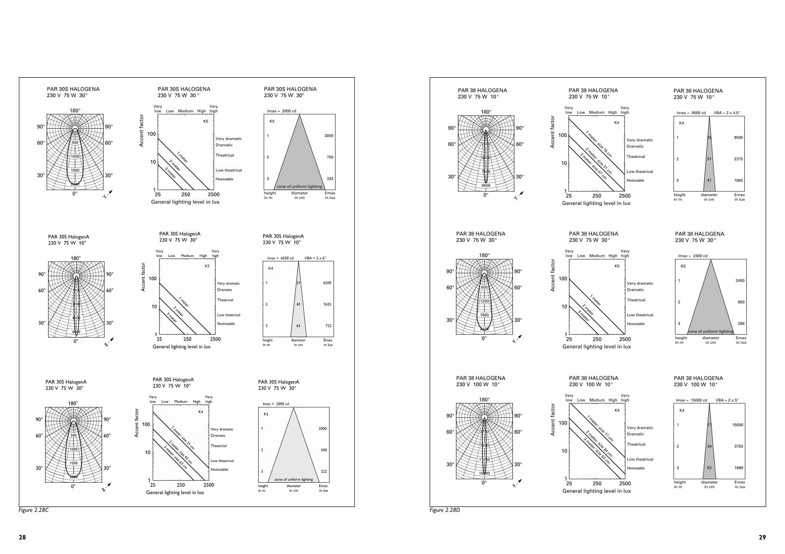
2.4.9 Luminous intensity distribution and visual impact diagrams
2.4.8 Electrical and lighting data
Lamp type Wattage Voltage Beam Luminous Lamp base(W) (V) angle intensity (cd)
PAR 16 SPOT 40 230/240 10 2500 E14PAR 16 FLOOD 40 230/240 30 850 E14PAR 20 SPOT 50 230/240 10 3500 E27PAR 20 FLOOD 50 230/240 30 1000 E27PAR 30S SPOT 75 230/240 10 6500 E27PAR 30S SPOT 100 230/240 10 9000 E27PAR 30S FLOOD 75 230/240 30 2000 E27PAR 30S FLOOD 100 230/240 30 3000 E27PAR 38 SPOT 75 230/240 10 9200-9500 E27PAR 38 FLOOD 75 230/240 30 2200-2400 E27PAR 38 SPOT 100 230/240 10 11600-15000 E27PAR 38 FLOOD 100 230/240 30 3000 E27
Note:The average lifetime for PAR 20, PAR 30L, PAR 30S and PAR 38 lamps is 2500 hours.
1000
2000
4000
180°
0°
90°
60°
30°
90°
60°
30°
g
PAR 16 HALOGENA230 V 40 W 10°
3000
PAR 16 HALOGENA230 V 40 W 10 °
100
Acc
ent
fact
or
General lighting level in lux
Low HighMedium
10
1
Verylow
Very dramatic
Dramatic
Theatrical
Low theatrical
Noticeable
25 250 2500
Veryhigh
1 meter: size 31 cm
2 meter: size 62 cm
3 meter: size 93 cm
K4
PAR 16 HALOGENA230 V 40 W 10°
1
2
3
2500
700
300
Imax = 2500 cd
heightin m
diameterin cm
Emaxin lux
31
62
93
K4
200
400
600
800
180°
0°
90°
60°
30°
90°
60°
30°
g
PAR 16 HALOGENA230 V 40 W 30°
PAR 16 HALOGENA230 V 40 W 30 °
100
Acc
ent
fact
or
General lighting level in lux
Low HighMedium
10
1
Verylow
Very dramatic
Dramatic
Theatrical
Low theatrical
25 250 2500
Veryhigh
K5
3 meter2 meter
1 meter
Noticeable
PAR 16 HALOGENA230 V 40 W 30°
zone of uniform lighting
1
2
3
850
215
95
Imax = 850 cd
heightin m
diameterin cm
Emaxin lux
K5
Figure 2.28A
2928
180°
0°
90°
60°
30°
90°
60°
30°
γ
PAR 38 HALOGENA230 V 75 W 10°
2500
5000
7500
9500
PAR 38 HALOGENA230 V 75 W 10°
100
Acc
ent
fact
or
General lighting level in lux
Low HighMedium
10
1
Verylow
Very dramatic
Dramatic
Theatrical
Low theatrical
25 250 2500
Veryhigh
K4
1 meter: size 15 cm
2 meter: size 31 cm
3 meter: size 47 cm
Noticeable
K4
1
2
3
9500
2375
1055
15
31
47
PAR 38 HALOGENA230 V 75 W 10°
Imax = 9500 cd VBA = 2 x 4.5°
heightin m
diameterin cm
Emaxin lux
180°
0°
90°
60°
30°
90°
60°
30°
γ
PAR 38 HALOGENA230 V 75 W 30°
600
1200
1800
2400
K5
PAR 38 HALOGENA230 V 75 W 30 °
100
Acc
ent
fact
or
General lighting level in lux
Low HighMedium
10
1
Verylow
Very dramatic
Dramatic
Theatrical
Low theatrical
25 250 2500
Veryhigh
1 meter2 m
eter
3 meter
Noticeable
K5
1
2
3
2400
600
266
zone of uniform lighting
PAR 38 HALOGENA230 V 75 W 30°
Imax = 2400 cd
heightin m
diameterin cm
Emaxin lux
3750
7500
11250
15000
180°
0°
90°
60°
30°
90°
60°
30°
γ
PAR 38 HALOGENA230 V 100 W 10°
PAR 38 HALOGENA230 V 100 W 10 °
100
Acc
ent
fact
or
General lighting level in lux
Low HighMedium
10
1
Verylow
Very dramatic
Dramatic
Theatrical
Low theatrical
25 250 2500
Veryhigh
K4
1 meter: size 17 cm
2 meter: size 34 cm
3 meter: size 52 cm
Noticeable
K4
1
2
3
15000
3750
1666
17
34
52
PAR 38 HALOGENA230 V 100 W 10°
Imax = 15000 cd VBA = 2 x 5°
heightin m
diameterin cm
Emaxin lux
Figure 2.28D
500
1000
1500
2000
180°
0°
90°
60°
30°
90°
60°
30°
γ
PAR 30S HALOGENA230 V 75 W 30°
K5
PAR 30S HALOGENA230 V 75 W 30 °
100A
ccen
t fa
cto
r
General lighting level in lux
Low HighMedium
10
1
Verylow
Very dramatic
Dramatic
Theatrical
Low theatrical
25 250 2500
Veryhigh
1 meter2 m
eter3 meter
Noticeable
PAR 30S HALOGENA230 V 75 W 30°
Imax = 2000 cd
heightin m
diameterin cm
Emaxin lux
K5
1
2
3
3000
750
333
zone of uniform lighting
1500
3000
4500
6000
180°
0°
90°
60°
30°
90°
60°
30°
g
PAR 30S HalogenA230 V 75 W 10°
K5
PAR 30S HalogenA230 V 75 W 30°
100
Acc
ent
fact
or
General lighting level in lux
Low HighMedium
10
1
Verylow
Very dramatic
Dramatic
Theatrical
Low theatrical
25 250 2500
Veryhigh
1 meter2 meter3 meter
Noticeable
K4
1
2
3
6500
1625
722
21
42
63
PAR 30S HalogenA230 V 75 W 10°
Imax = 6500 cd VBA = 2 x 6°
heightin m
diameterin cm
Emaxin lux
Figure 2.28C
500
1000
1500
2000
180°
0°
90°
60°
30°
90°
60°
30°
g
PAR 30S HalogenA230 V 75 W 30°
K4
1 meter: size 21 cm
2 meter: size 42 cm
3 meter: size 63 cm
PAR 30S HalogenA230 V 75 W 10°
100
Acc
ent
fact
or
General lighting level in lux
Low HighMedium
10
1
Verylow
Very dramatic
Dramatic
Theatrical
Low theatrical
25 250 2500
Veryhigh
Noticeable
PAR 30S HalogenA230 V 75 W 30°
Imax = 2000 cd
heightin m
diameterin cm
Emaxin lux
K5
1
2
3
2000
500
222
zone of uniform lighting

3130
2.4.10 Lamp disposal
Refer chapter 1.6 in this brochure.
2.4.11 Lifetime performance
Typical life expectancy and lumen maintenance curves for PAR HalogenA lamps are shown in figure 2.29
2.4.12 Influence of mains voltage on lamp characteristics
See figure 2.30
2.4.13 Dimming
All Philips PAR HalogenA lamps are dimmable,see also chapter 1.4.
2.4.14 Burning positions
The PAR HalogenA lamps have a universal burningposition.
W
lm/W
lm
W
lm/W
lm
Life
40
60
80
100
120
140
160%
90 95 100 105 110V
Figure 2.30
Figure 2.29
Life expectancy
Lamp type:Mains voltage Halogen- Reflector- PAR 20 HALOGENA- PAR 30S HALOGENA- PAR 38 HALOGENA
Lumen maintenance
Lamp type:Mains voltage Halogen- Reflector- PAR 20 HALOGENA- PAR 30S HALOGENA- PAR 38 HALOGENA
050
60
70
80
90
100PAR HalogenA
750 1500 2250 3000 3750 4500
Su
rviv
als
in %
Burning hours
050
60
70
80
90
100PAR HalogenA
750 1500 2250 3000 3750 4500
Lum
en in
%
Burning hours
750
1500
2250
3000
180°
0°
90°
60°
30°
90°
60°
30°
γ
PAR 38 HALOGENA230 V 100 W 30 °
K5
PAR 38 HALOGENA230 V 100 W 30 °
100A
ccen
t fa
cto
r
General lighting level in lux
Low HighMedium
10
1
Verylow
Very dramatic
Dramatic
Theatrical
Low theatrical
25 250 2500
Veryhigh
1 meter2 m
eter
3 meter
Noticeable
K5
1
2
3
3000
750
333
zone of uniform lighting
PAR 38 HALOGENA230 V 100 W 30 °
Imax = 3000 cd
heightin m
diameterin cm
Emaxin lux
Figure 2.28E

2.5.6 Lamp dimensions
NR 50
NR 63
2.5.7 Luminous intensity distribution
Currently being measured
2.5.8 Spectral irradiance, transmitted wavelengths and UV – Block
The graph below shows the spectral irradiance and the transmittedwavelength of UV block. UV Block burners have a PET ≥ 100 hourswhich is far better than the ACGIH recommendations at 1000 lux(permissible exposure time per 24 hours)
Graph to be created
2.5.9 Lamp disposal
Refer to chapter 1.6 in this brochure
2.5.10 Lifetime performance
under preparation
2.5.11 Influence of mains voltage on lampcharacteristics
2.5.12 Dimming
All Philips mains voltage burner products can be dimmed
2.5.13 Fuse
The Philips mains voltage capsules are provided with a patented fusesystem in the pinch of the lamp
At end of life the lampFilament can break Causing an arc. RisingTemperature can causePinch to explode.
The MV capsule has a small open area around the coilLeg. The arc reaches this area, which creates a vacuum, which extinguishes the arc completely.
2.5.14 Burning position
All Philips mains voltage capsules have a universal burning positionand are therefore suitable for a variety of applications as previouslyindicated
33
2.5.1 Introduction and description
The Halogen reflector R50 and R63 in standard GLS shaped lampscontain a halogen burner inside. The reflectors offer an improvedlight quality and output with an extended 2 year lifetime. Theselamps can be considered as a consumer alternative to Par 16 andPar 20 lamps.
Features and Benefits
Benefits Features
GLS standard lamp with •Higher Luminous efficacybenefits of a Halogen •Colour temp 2800º Kburner. •Ra = 100It has a warm ’wohn’ light. •2000 hours burningExcellent colour rendering.A longer life compared withGLS equivalent
Suitable for various •Universal burning positionapplications •Dimmable
•Standard E27, B22, E14 base
No transformer required •Patented fuse effect.•UV block quartz glass
The Halogen reflector lamps offer benefits to luminaireManufacturers:
1. Less expensive than PAR lamps2. No transformer is required so system costs are less.3. Twice life of standard GLS.
ApplicationsThe capsule will be mainly suited for lighting in homes in wall, ceilingand table consumer luminaires.
2.5.2 Application IEC standards
IEC 432-1, 2, IEC 630
2.5.3 Position of components(lamp construction)
2.5.4 PET values
Mains voltage halogen reflector ≥ 100 (at 1000 LUX) in hoursRefer to chapter 1.3 of this brochure
2.5.5 Range with electrical and lighting data
Commercial 10 NC W V Luminous Cap / Lampname Intensity Base life 50%
Cd hoursNR 63 9248 200 44200 40W 230V 680 E27 2000NR 63 9248 201 44200 60W 230V 1160 E27 2000NR 63 9248 202 45500 40W 240V 680 B22 2000NR 63 9248 203 45500 60W 240V 1160 B22 2000NR 50 9248 204 44200 40W 230V 440 E14 2000NR 50 9248 205 44200 40W 240V 440 E14 2000NR 63 9248 206 45500 40W 240V 680 E27 2000NR 63 9248 207 45500 60W 240V 1160 E27 2000
2.5 - Halogen Reflector Lamps
32
1. GLS Bulb
2. Satinised coating
3. Mains Voltage Halogen Burner
4. Assembly Clip
5. GLS Stem
6. GLS Cap
C
D
C
D
C 85 mmD 50 mm
C 103 mmD 63 mm
W
lm/W
lm
W
lm/W
lm
Life
40
60
80
100
120
140
160%
90 95 100 105 110V
3534
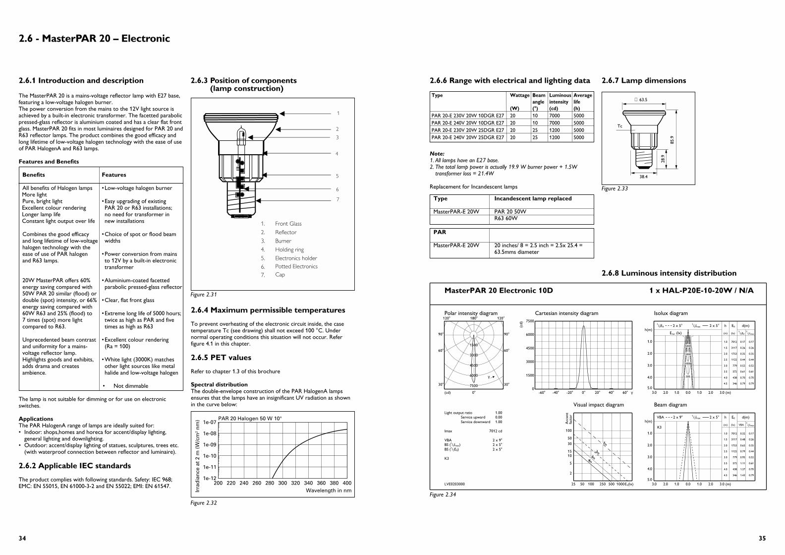
2.6.7 Lamp dimensions
2.6.8 Luminous intensity distribution
Type Incandescent lamp replaced
MasterPAR-E 20W PAR 20 50WR63 60W
PAR
MasterPAR-E 20W 20 inches/ 8 = 2.5 inch = 2.5x 25.4 =63.5mms diameter
∅ 63.5
Tc
85.9
38.4
28.9
2.6.3 Position of components (lamp construction)
2.6.4 Maximum permissible temperatures
To prevent overheating of the electronic circuit inside, the casetemperature Tc (see drawing) shall not exceed 100 °C. Undernormal operating conditions this situation will not occur. Referfigure 4.1 in this chapter.
2.6.5 PET values
Refer to chapter 1.3 of this brochure
Spectral distributionThe double-envelope construction of the PAR HalogenA lampsensures that the lamps have an insignificant UV radiation as shownin the curve below:
2.6.1 Introduction and description
The MasterPAR 20 is a mains-voltage reflector lamp with E27 base,featuring a low-voltage halogen burner. The power conversion from the mains to the 12V light source isachieved by a built-in electronic transformer. The facetted parabolicpressed-glass reflector is aluminium coated and has a clear flat frontglass. MasterPAR 20 fits in most luminaires designed for PAR 20 andR63 reflector lamps. The product combines the good efficacy andlong lifetime of low-voltage halogen technology with the ease of useof PAR HalogenA and R63 lamps.
Features and Benefits
Benefits Features
All benefits of Halogen lamps •Low-voltage halogen burnerMore lightPure, bright light •Easy upgrading of existingExcellent colour rendering PAR 20 or R63 installations;Longer lamp life no need for transformer inConstant light output over life new installations
Combines the good efficacy •Choice of spot or flood beamand long lifetime of low-voltage widthshalogen technology with the ease of use of PAR halogen •Power conversion from mainsand R63 lamps. to 12V by a built-in electronic
transformer
20W MasterPAR offers 60% •Aluminium-coated facettedenergy saving compared with parabolic pressed-glass reflector50W PAR 20 similar (flood) or double (spot) intensity, or 66% •Clear, flat front glassenergy saving compared with 60W R63 and 25% (flood) to •Extreme long life of 5000 hours;7 times (spot) more light twice as high as PAR and fivecompared to R63. times as high as R63
Unprecedented beam contrast •Excellent colour renderingand uniformity for a mains- (Ra = 100)voltage reflector lamp. Highlights goods and exhibits, •White light (3000K) matchesadds drama and creates other light sources like metalambience. halide and low-voltage halogen
• Not dimmable
The lamp is not suitable for dimming or for use on electronicswitches.
ApplicationsThe PAR HalogenA range of lamps are ideally suited for:• Indoor: shops,homes and horeca for accent/display lighting,
general lighting and downlighting.• Outdoor: accent/display lighting of statues, sculptures, trees etc.
(with waterproof connection between reflector and luminaire).
2.6.2 Applicable IEC standards
The product complies with following standards. Safety: IEC 968;EMC: EN 55015, EN 61000-3-2 and EN 55022; EMI: EN 61547.
2.6 - MasterPAR 20 – Electronic
1. Front Glass
2. Reflector
3. Burner
4.
5.
Holding ring
6.
Electronics holder
7.
Potted ElectronicsCap
1
2
3
4
6
5
7
Figure 2.32Figure 2.34
Figure 2.31
200 220 240 260 280 300 320 340 360 380 4001e-12
1e-11
1e-10
1e-09
1e-08
1e-07PAR 20 Halogen 50 W 10°
Wavelength in nmIrra
dia
nce
at
2 m
(W
/cm
2 nm
)
Type Wattage Beam Luminous Averageangle intensity life
(W) (°) (cd) (h)PAR 20-E 230V 20W 10DGR E27 20 10 7000 5000PAR 20-E 240V 20W 10DGR E27 20 10 7000 5000PAR 20-E 230V 20W 25DGR E27 20 25 1200 5000PAR 20-E 240V 20W 25DGR E27 20 25 1200 5000
2.6.6 Range with electrical and lighting data
Note:1. All lamps have an E27 base.2. The total lamp power is actually 19.9 W burner power + 1.5W
transformer loss = 21.4W
Replacement for Incandescent lamps
MasterPAR 20 Electronic 10D 1 x HAL-P20E-10-20W / N/A
LVE0203000
Light output ratio 1.00Service upward 0.00Service downward 1.00
Imax 7012 cd
VBA o2 x 9BS (1/2Imax)
o2 x 5BS (1/2E0)
o2 x 5
K3
Polar intensity diagram
(cd) 0o
180o
30oo30
60oo60
90oo90
120oo120
1500
3000
4500
6000
7500
γ
Cartesian intensity diagram
(cd)
0
1500
3000
4500
6000
7500
-60o -40o -20o 0o 20o 40o 60o γ
Isolux diagram
hh(m)
(m) (lx)1/2E0
1/2Imax
E0 d(m)
(lx)horE
1.0
2.0
3.0
4.0
5.03.0 2.0 1.0 0.0 1.0 2.0 3.0 (m)
1.0 7012 0.17 0.17
1.5 3117 0.26 0.26
2.0 1753 0.35 0.35
2.5 1122 0.44 0.44
3.0 779 0.52 0.52
3.5 572 0.61 0.61
4.0 438 0.70 0.70
4.5 346 0.79 0.79
o2 x 5maxI2/11/2E0 2 x 5o
5000
2000
1000
500
Visual impact diagram
Acc
ent
fact
or
2
5
1015
30
50
100
Eh(lx)25 50 100 250 500 1000
4m3m
2m
1m
Beam diagram
hh(m)
(m) (lx) VBA1/2Imax
E0 d(m)
K3
1.0
2.0
3.0
4.0
5.03.0 2.0 1.0 0.0 1.0 2.0 3.0 (m)
1.0 7012 0.32 0.17
1.5 3117 0.48 0.26
2.0 1753 0.63 0.35
2.5 1122 0.79 0.44
3.0 779 0.95 0.52
3.5 572 1.11 0.61
4.0 438 1.27 0.70
4.5 346 1.43 0.79
o2 x 5maxI2/1VBA 2 x 9o
Figure 2.33
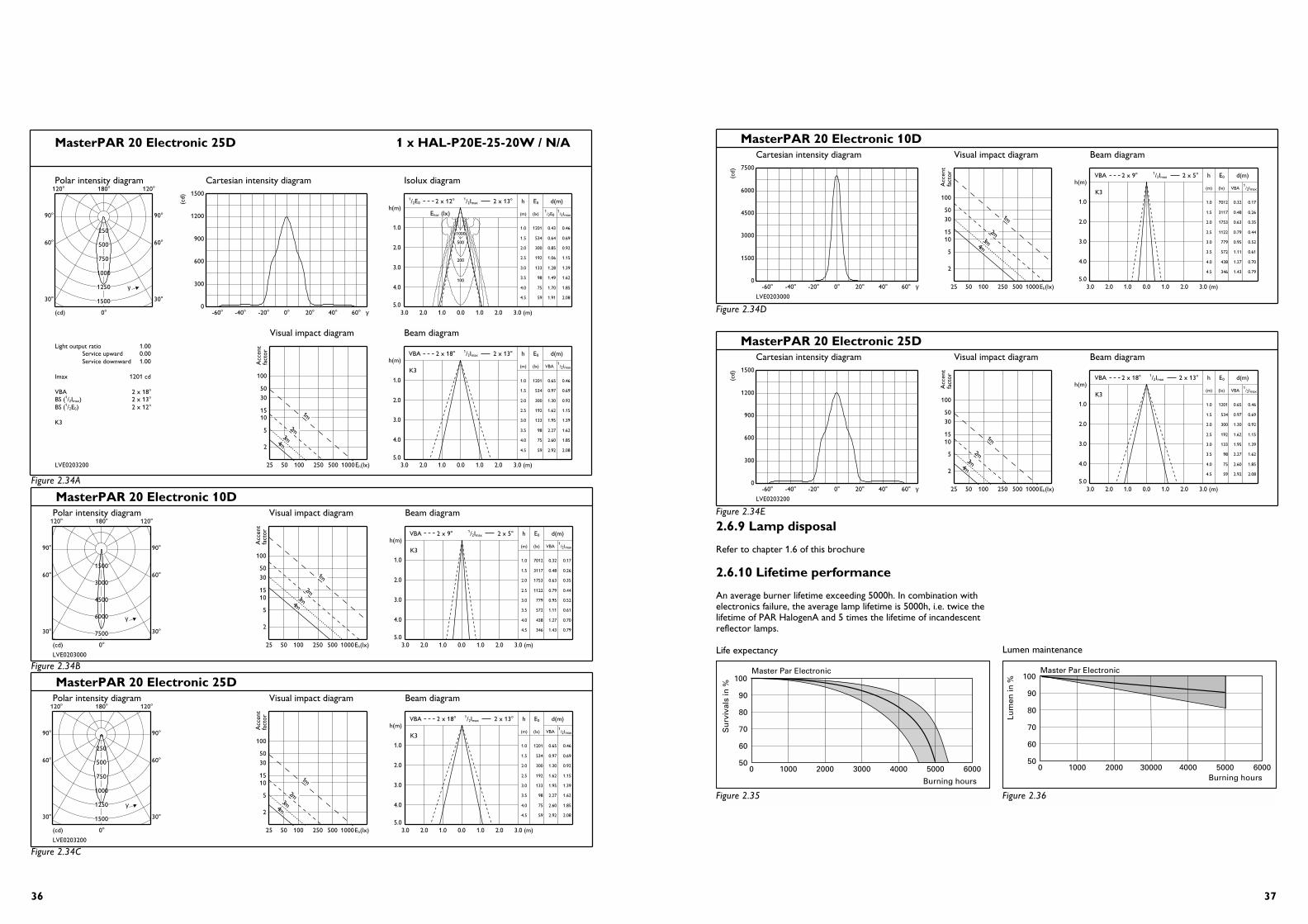
3736
Lumen maintenance
MasterPAR 20 Electronic 10D
LVE0203000
Cartesian intensity diagram
(cd)
0
1500
3000
4500
6000
7500
-60o -40o -20o 0o 20o 40o 60o γ
Visual impact diagram
Acc
ent
fact
or
2
5
1015
30
50
100
Eh(lx)25 50 100 250 500 1000
4m3m
2m
1m
Beam diagram
hh(m)
(m) (lx) VBA1/2Imax
E0 d(m)
K3
1.0
2.0
3.0
4.0
5.03.0 2.0 1.0 0.0 1.0 2.0 3.0 (m)
1.0 7012 0.32 0.17
1.5 3117 0.48 0.26
2.0 1753 0.63 0.35
2.5 1122 0.79 0.44
3.0 779 0.95 0.52
3.5 572 1.11 0.61
4.0 438 1.27 0.70
4.5 346 1.43 0.79
o2 x 5maxI2/1VBA 2 x 9o
MasterPAR 20 Electronic 25D
LVE0203200
Cartesian intensity diagram
(cd)
0
300
600
900
1200
1500
-60o -40o -20o 0o 20o 40o 60o γ
Visual impact diagram
Acc
ent
fact
or
2
5
1015
30
50
100
Eh(lx)25 50 100 250 500 1000
4m3m
2m
1m
Beam diagram
hh(m)
(m) (lx) VBA1/2Imax
E0 d(m)
K3
1.0
2.0
3.0
4.0
5.03.0 2.0 1.0 0.0 1.0 2.0 3.0 (m)
1.0 1201 0.65 0.46
1.5 534 0.97 0.69
2.0 300 1.30 0.92
2.5 192 1.62 1.15
3.0 133 1.95 1.39
3.5 98 2.27 1.62
4.0 75 2.60 1.85
4.5 59 2.92 2.08
o2 x 13maxI2/1VBA 2 x 18o
050
60
70
80
90
100
1000 2000 3000 4000 5000 6000
Su
rviv
als
in %
Burning hours
Master Par Electronic
Figure 2.35
50
60
70
80
90
100
0 1000 2000 30000 4000 5000 6000
Lum
en in
%
Burning hours
Master Par Electronic
Figure 2.36
MasterPAR 20 Electronic 25D 1 x HAL-P20E-25-20W / N/A
LVE0203200
Light output ratio 1.00Service upward 0.00Service downward 1.00
Imax 1201 cd
VBA o2 x 18BS (1/2Imax)
o2 x 13BS (1/2E0)
o2 x 12
K3
Polar intensity diagram
(cd) 0o
180o
30oo30
60oo60
90oo90
120oo120
250
500
750
1000
1250
1500
γ
Cartesian intensity diagram(c
d)
0
300
600
900
1200
1500
-60o -40o -20o 0o 20o 40o 60o γ
Isolux diagram
hh(m)
(m) (lx)1/2E0
1/2Imax
E0 d(m)
(lx)horE
1.0
2.0
3.0
4.0
5.03.0 2.0 1.0 0.0 1.0 2.0 3.0 (m)
1.0 1201 0.43 0.46
1.5 534 0.64 0.69
2.0 300 0.85 0.92
2.5 192 1.06 1.15
3.0 133 1.28 1.39
3.5 98 1.49 1.62
4.0 75 1.70 1.85
4.5 59 1.91 2.08
o2 x 13maxI2/11/2E0 2 x 12o
1000
500
200
100
Visual impact diagram
Acc
ent
fact
or
2
5
1015
30
50
100
Eh(lx)25 50 100 250 500 1000
4m3m
2m
1m
Beam diagram
hh(m)
(m) (lx) VBA1/2Imax
E0 d(m)
K3
1.0
2.0
3.0
4.0
5.03.0 2.0 1.0 0.0 1.0 2.0 3.0 (m)
1.0 1201 0.65 0.46
1.5 534 0.97 0.69
2.0 300 1.30 0.92
2.5 192 1.62 1.15
3.0 133 1.95 1.39
3.5 98 2.27 1.62
4.0 75 2.60 1.85
4.5 59 2.92 2.08
o2 x 13maxI2/1VBA 2 x 18o
MasterPAR 20 Electronic 10D
LVE0203000
Polar intensity diagram
(cd) 0o
180o
30oo30
60oo60
90oo90
120oo120
1500
3000
4500
6000
7500
γ
Visual impact diagram
Acc
ent
fact
or
2
5
1015
30
50
100
Eh(lx)25 50 100 250 500 1000
4m3m
2m
1m
Beam diagram
hh(m)
(m) (lx) VBA1/2Imax
E0 d(m)
K3
1.0
2.0
3.0
4.0
5.03.0 2.0 1.0 0.0 1.0 2.0 3.0 (m)
1.0 7012 0.32 0.17
1.5 3117 0.48 0.26
2.0 1753 0.63 0.35
2.5 1122 0.79 0.44
3.0 779 0.95 0.52
3.5 572 1.11 0.61
4.0 438 1.27 0.70
4.5 346 1.43 0.79
o2 x 5maxI2/1VBA 2 x 9o
MasterPAR 20 Electronic 25D
LVE0203200
Polar intensity diagram
(cd) 0o
180o
30oo30
60oo60
90oo90
120oo120
250
500
750
1000
1250
1500
γ
Visual impact diagram
Acc
ent
fact
or
2
5
1015
30
50
100
Eh(lx)25 50 100 250 500 1000
4m3m
2m
1m
Beam diagram
hh(m)
(m) (lx) VBA1/2Imax
E0 d(m)
K3
1.0
2.0
3.0
4.0
5.03.0 2.0 1.0 0.0 1.0 2.0 3.0 (m)
1.0 1201 0.65 0.46
1.5 534 0.97 0.69
2.0 300 1.30 0.92
2.5 192 1.62 1.15
3.0 133 1.95 1.39
3.5 98 2.27 1.62
4.0 75 2.60 1.85
4.5 59 2.92 2.08
o2 x 13maxI2/1VBA 2 x 18o
2.6.9 Lamp disposal
Refer to chapter 1.6 of this brochure
2.6.10 Lifetime performance
An average burner lifetime exceeding 5000h. In combination withelectronics failure, the average lamp lifetime is 5000h, i.e. twice thelifetime of PAR HalogenA and 5 times the lifetime of incandescentreflector lamps.
Life expectancy
Figure 2.34A
Figure 2.34B
Figure 2.34C
Figure 2.34D
Figure 2.34E
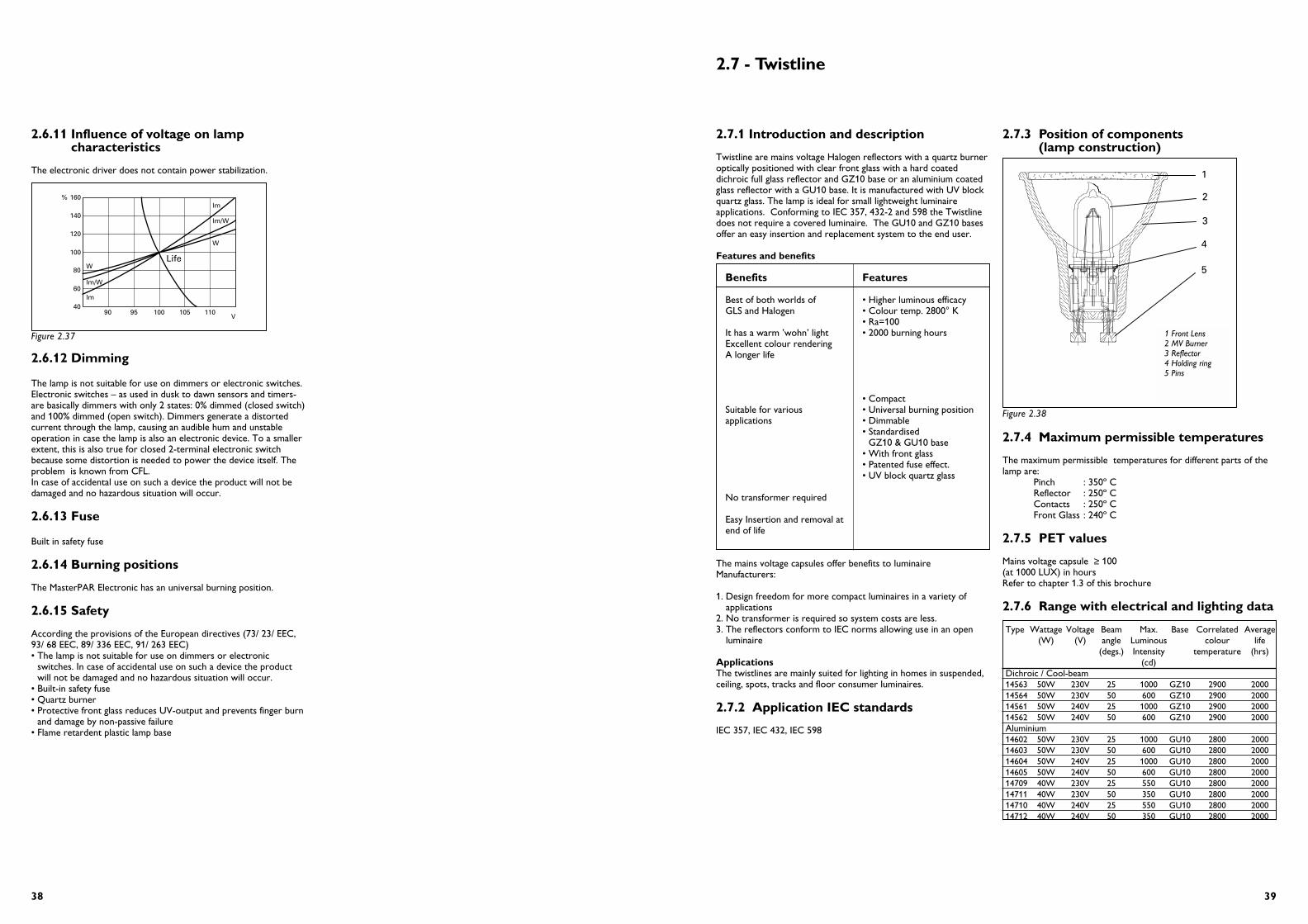
2.7.3 Position of components(lamp construction)
2.7.4 Maximum permissible temperatures
The maximum permissible temperatures for different parts of thelamp are:
Pinch : 350º CReflector : 250º CContacts : 250º CFront Glass : 240º C
2.7.5 PET values
Mains voltage capsule ≥ 100(at 1000 LUX) in hoursRefer to chapter 1.3 of this brochure
2.7.6 Range with electrical and lighting data
Type Wattage Voltage Beam Max. Base Correlated Average(W) (V) angle Luminous colour life
(degs.) Intensity temperature (hrs)(cd)
Dichroic / Cool-beam14563 50W 230V 25 1000 GZ10 2900 200014564 50W 230V 50 600 GZ10 2900 200014561 50W 240V 25 1000 GZ10 2900 200014562 50W 240V 50 600 GZ10 2900 2000Aluminium14602 50W 230V 25 1000 GU10 2800 200014603 50W 230V 50 600 GU10 2800 200014604 50W 240V 25 1000 GU10 2800 200014605 50W 240V 50 600 GU10 2800 200014709 40W 230V 25 550 GU10 2800 200014711 40W 230V 50 350 GU10 2800 200014710 40W 240V 25 550 GU10 2800 200014712 40W 240V 50 350 GU10 2800 2000
3938
2.7.1 Introduction and description
Twistline are mains voltage Halogen reflectors with a quartz burneroptically positioned with clear front glass with a hard coateddichroic full glass reflector and GZ10 base or an aluminium coatedglass reflector with a GU10 base. It is manufactured with UV blockquartz glass. The lamp is ideal for small lightweight luminaireapplications. Conforming to IEC 357, 432-2 and 598 the Twistlinedoes not require a covered luminaire. The GU10 and GZ10 basesoffer an easy insertion and replacement system to the end user.
Features and benefits
Benefits Features
Best of both worlds of • Higher luminous efficacyGLS and Halogen • Colour temp. 2800° K
• Ra=100It has a warm ’wohn’ light • 2000 burning hoursExcellent colour renderingA longer life
• CompactSuitable for various • Universal burning positionapplications • Dimmable
• Standardised GZ10 & GU10 base
• With front glass• Patented fuse effect.• UV block quartz glass
No transformer required
Easy Insertion and removal at end of life
The mains voltage capsules offer benefits to luminaireManufacturers:
1. Design freedom for more compact luminaires in a variety ofapplications
2. No transformer is required so system costs are less.3. The reflectors conform to IEC norms allowing use in an open
luminaire
ApplicationsThe twistlines are mainly suited for lighting in homes in suspended,ceiling, spots, tracks and floor consumer luminaires.
2.7.2 Application IEC standards
IEC 357, IEC 432, IEC 598
2.7 - Twistline
1 Front Lens2 MV Burner3 Reflector4 Holding ring5 Pins
1
2
3
4
5
1 Front Lens2 MV Burner3 Reflector4 Holding ring5 Pins
2.6.11 Influence of voltage on lampcharacteristics
The electronic driver does not contain power stabilization.
2.6.12 Dimming
The lamp is not suitable for use on dimmers or electronic switches.Electronic switches – as used in dusk to dawn sensors and timers-are basically dimmers with only 2 states: 0% dimmed (closed switch)and 100% dimmed (open switch). Dimmers generate a distortedcurrent through the lamp, causing an audible hum and unstableoperation in case the lamp is also an electronic device. To a smallerextent, this is also true for closed 2-terminal electronic switchbecause some distortion is needed to power the device itself. Theproblem is known from CFL.In case of accidental use on such a device the product will not bedamaged and no hazardous situation will occur.
2.6.13 Fuse
Built in safety fuse
2.6.14 Burning positions
The MasterPAR Electronic has an universal burning position.
2.6.15 Safety
According the provisions of the European directives (73/ 23/ EEC,93/ 68 EEC, 89/ 336 EEC, 91/ 263 EEC) • The lamp is not suitable for use on dimmers or electronic
switches. In case of accidental use on such a device the productwill not be damaged and no hazardous situation will occur.
• Built-in safety fuse• Quartz burner• Protective front glass reduces UV-output and prevents finger burn
and damage by non-passive failure• Flame retardent plastic lamp base
W
lm/W
lm
W
lm/W
lm
Life
40
60
80
100
120
140
160%
90 95 100 105 110V
Figure 2.37
Figure 2.38
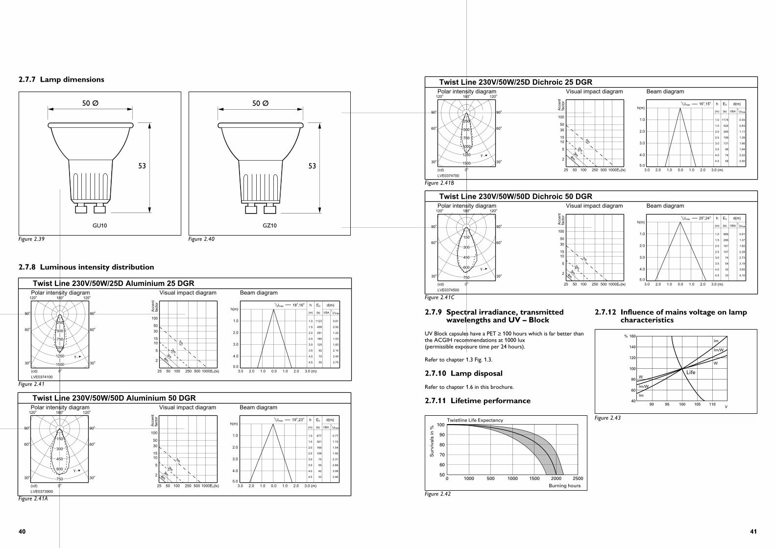
4140
Twist Line 230V/50W/50D Aluminium 50 DGR
LVE0373900
Polar intensity diagram
(cd) 0o
180o
30oo30
60oo60
90oo90
120oo120
150
300
450
600
750
γ
Visual impact diagram
Acc
ent
fact
or
2
5
1015
30
50
100
Eh(lx)25 50 100 250 500 1000
4m3m
2m
1m
Beam diagram
hh(m)
(m) (lx) VBA1/2Imax
E0 d(m)
1.0
2.0
3.0
4.0
5.03.0 2.0 1.0 0.0 1.0 2.0 3.0 (m)
1.0 677 0.77
1.5 301 1.15
2.0 169 1.54
2.5 108 1.92
3.0 75 2.31
3.5 55 2.69
4.0 42 3.08
4.5 33 3.46
o,23o19maxI2/1
Twist Line 230V/50W/25D Aluminium 25 DGR
LVE0374100
Polar intensity diagram
(cd) 0o
180o
30oo30
60oo60
90oo90
120oo120
250
500
750
1000
1250
1500
γ
Visual impact diagram
Acc
ent
fact
or
2
5
1015
30
50
100
Eh(lx)25 50 100 250 500 1000
4m3m
2m
1m
Beam diagram
hh(m)
(m) (lx) VBA1/2Imax
E0 d(m)
1.0
2.0
3.0
4.0
5.03.0 2.0 1.0 0.0 1.0 2.0 3.0 (m)
1.0 1123 0.61
1.5 499 0.92
2.0 281 1.22
2.5 180 1.53
3.0 125 1.83
3.5 92 2.14
4.0 70 2.45
4.5 55 2.75
o,16o18maxI2/1
2.7.7 Lamp dimensions
2.7.8 Luminous intensity distribution
50 Ø
53
50 Ø
53
GU10 GZ10
Figure 2.39
Figure 2.41
Figure 2.41A
Figure 2.41B
Figure 2.41C
Figure 2.42
Figure 2.40
Twist Line 230V/50W/25D Dichroic 25 DGR
LVE0374700
Polar intensity diagram
(cd) 0o
180o
30oo30
60oo60
90oo90
120oo120
250
500
750
1000
1250
1500
γ
Visual impact diagram
Acc
ent
fact
or
2
5
1015
30
50
100
Eh(lx)25 50 100 250 500 1000
4m3m
2m
1m
Beam diagram
hh(m)
(m) (lx) VBA1/2Imax
E0 d(m)
1.0
2.0
3.0
4.0
5.03.0 2.0 1.0 0.0 1.0 2.0 3.0 (m)
1.0 1178 0.55
1.5 524 0.83
2.0 295 1.11
2.5 189 1.39
3.0 131 1.66
3.5 96 1.94
4.0 74 2.22
4.5 58 2.50
o,15o16maxI2/1
Twist Line 230V/50W/50D Dichroic 50 DGR
LVE0374500
Polar intensity diagram
(cd) 0o
180o
30oo30
60oo60
90oo90
120oo120
150
300
450
600
750
γ
Visual impact diagram
Acc
ent
fact
or
2
5
1015
30
50
100
Eh(lx)25 50 100 250 500 1000
4m3m
2m
1m
Beam diagram
hh(m)
(m) (lx) VBA1/2Imax
E0 d(m)
1.0
2.0
3.0
4.0
5.03.0 2.0 1.0 0.0 1.0 2.0 3.0 (m)
1.0 666 0.91
1.5 296 1.37
2.0 167 1.82
2.5 107 2.28
3.0 74 2.73
3.5 54 3.19
4.0 42 3.65
4.5 33 4.10
o,24o25maxI2/1
2.7.9 Spectral irradiance, transmittedwavelengths and UV – Block
UV Block capsules have a PET ≥ 100 hours which is far better thanthe ACGIH recommendations at 1000 lux (permissible exposure time per 24 hours).
Refer to chapter 1.3 Fig. 1.3.
2.7.10 Lamp disposal
Refer to chapter 1.6 in this brochure.
2.7.11 Lifetime performance
2.7.12 Influence of mains voltage on lampcharacteristics
W
lm/W
lm
W
lm/W
lm
Life
40
60
80
100
120
140
160%
90 95 100 105 110V
Figure 2.43
050
60
70
80
90
100
1000 500 1000 1500 2000 2500
Su
rviv
als
in %
Burning hours
Twistline Life Expectancy

4342
2.8.1 Introduction and description
This single-ended mains-voltage capsule is the most compactcapsule in its range. It is manufactured with UV block quartz glass.The capsule is ideal for small lightweight luminaire applications.Conforming to IEC 357, 432-2 and 598 the capsule does notrequire a covered luminaire. The frosted versions give softer lighteffects. The G9 base offers an easy insertion and replacementsystem to the end user.
Features and benefits
Benefits Features
Best of both worlds of • Higher luminous efficacyGLS and Halogen • Holour temp. 2800° K
• Ra=100It has a warm ’wohn’ light • 2000 burning hoursExcellent colour renderingA longer life
• Ultra compactSuitable for various • Universal burning positionapplications • Dimmable
• Standardised G9 base• Free burning without front
glass• Clear and Frosted versions• Patented fuse effect.• UV block quartz glass
No transformer required
Easy Insertion and removal at end of life
The mains voltage capsules offer benefits to luminaireManufacturers:
1. Design freedom for more compact luminaires in a variety ofapplications
2. No transformer is required so system costs are less.3. The capsule conforms to IEC norms allowing use in an open
luminaire
Applications:The capsule will be mainly suited for lighting in homes in wall,ceiling and table consumer luminaires.
2.8.2 Application IEC standards
IEC 357, IEC 432, IEC 598
2.8.3 Position of components(lamp construction)
2.8.4 Maximum permissible temperatures
The maximum permissible temperatures for different parts of thelamp are:
Pinch : 350º CBulb : 900º CContacts : 250º C
2.8.5 PET values
Mains voltage capsule ≥ 100(at 1000 LUX) in hoursRefer to chapter 1.3 of this brochure
2.8.6 Range with electrical and lighting data
Type Wattage Voltage Luminous Base Finish Average(W) (V) Flux (lm) life (hrs)
14683 40W 230V 490 G9 CLEAR 200014684 40W 230V 460 G9 FROSTED 200014689 60W 230V 820 G9 CLEAR 200014690 60W 230V 790 G9 FROSTED 200014694 40W 240V 490 G9 CLEAR 200014695 40W 240V 460 G9 FROSTED 200014700 60W 240V 820 G9 CLEAR 200014701 60W 240V 790 G9 FROSTED 2000
2.8 - Clickline
1 Bulb2 Coil3 Gas filling4 Coil support5 Pinch foil6 Lead in wire
1
2
3
4
5
6
43
2.7.13 Dimming
All Philips mains voltage capsules can be dimmed.
2.7.14 Fuse
The Philips mains voltage capsules are provided with a patentedfuse system in the pinch of the lamp.
At end of life the lampFilament can break Causing an arc. RisingTemperature can causePinch to explode.
The MV capsule has a small open area around the coilLeg. The arc reaches this area, which creates a vacuum, which extinguishesthe arc completely.
2.7.15 Burning position
Philips mains voltage Twistlines have a universal burning positionand are therefore suitable for a variety of applications as previouslyindicated.
Figure 2.44

44
Chapter 3
Low voltage Halogen lamps
2.8.7 Lamp dimensions
2.8.8 Spectral irradiance, transmittedwavelengths and UV – Block
UV Block capsules have a PET ≥ 100 hours which is far better thanthe ACGIH recommendations at 1000 lux ( permissible exposuretime per 24 hours).
Refer to chapter 1.3 Fig. 1.3.
2.8.9 Lamp disposal
Refer to chapter 1.6 in this brochure.
2.8.10 Lifetime performance
2.8.11 Influence of mains voltage on lampcharacteristics
2.8.12 Dimming
All Philips mains voltage capsules can be dimmed.
2.8.13 Fuse
The Philips mains voltage capsules are provided with a patented fusesystem in the pinch of the lamp.
At end of life the lampFilament can break Causing an arc. RisingTemperature can causePinch to explode.
The MV capsule has a small open areaaround the coil leg. The arc reaches this area, which creates avacuum, which extinguishes the arc completely.
2.8.14 Burning position
All Philips mains voltage capsules have a universal burning positionand are therefore suitable for a variety of applications as previouslyindicated.
W
lm/W
lm
W
lm/W
lm
Life
40
60
80
100
120
140
160%
90 95 100 105 110V
Figure 2.47
∅ 12.75 max.
44.0
max
.
Figure 2.45
050
60
70
80
90
100
1000 500 1000 1500 2000 2500
Su
rviv
als
in %
Burning hours
Clickline Life Expectancy
Figure 2.46
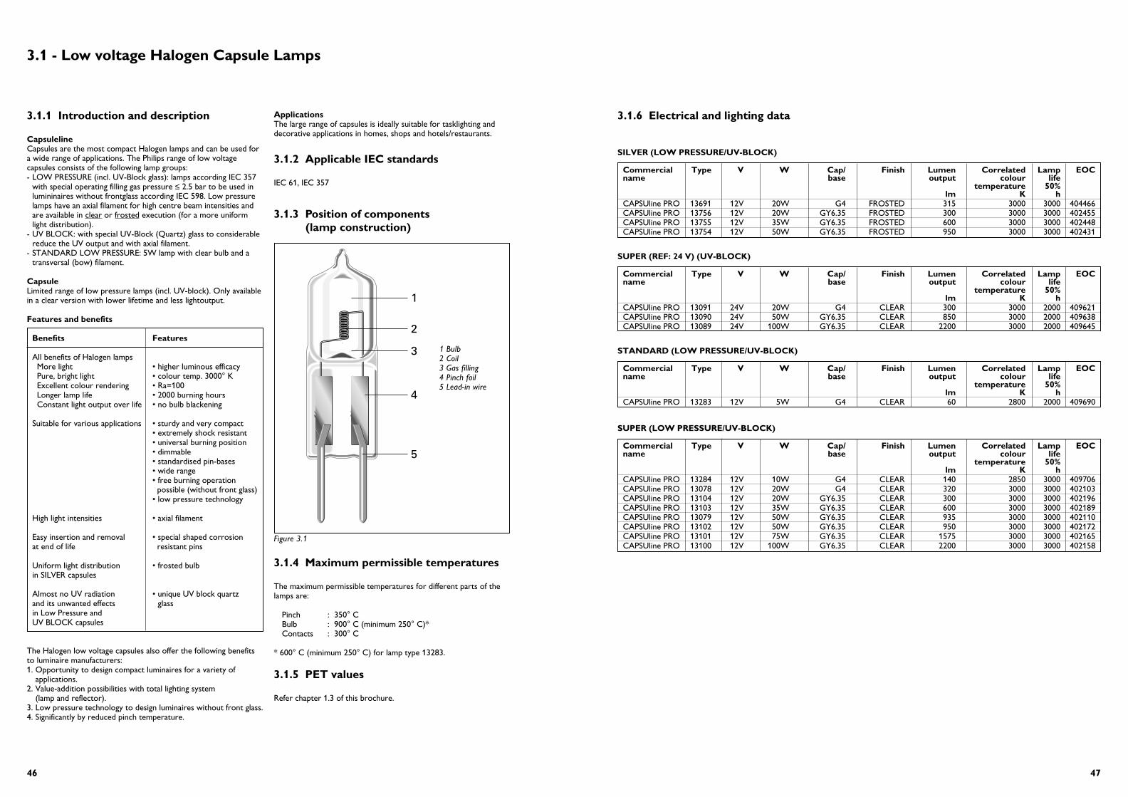
4746
SILVER (LOW PRESSURE/UV-BLOCK)
Commercial Type V W Cap/ Finish Lumen Correlated Lamp EOCname base output colour life
temperature 50%lm K h
CAPSUline PRO 13691 12V 20W G4 FROSTED 315 3000 3000 404466CAPSUline PRO 13756 12V 20W GY6.35 FROSTED 300 3000 3000 402455CAPSUline PRO 13755 12V 35W GY6.35 FROSTED 600 3000 3000 402448CAPSUline PRO 13754 12V 50W GY6.35 FROSTED 950 3000 3000 402431
3.1.6 Electrical and lighting data
SUPER (REF: 24 V) (UV-BLOCK)
Commercial Type V W Cap/ Finish Lumen Correlated Lamp EOCname base output colour life
temperature 50%lm K h
CAPSUline PRO 13091 24V 20W G4 CLEAR 300 3000 2000 409621CAPSUline PRO 13090 24V 50W GY6.35 CLEAR 850 3000 2000 409638CAPSUline PRO 13089 24V 100W GY6.35 CLEAR 2200 3000 2000 409645
STANDARD (LOW PRESSURE/UV-BLOCK)
Commercial Type V W Cap/ Finish Lumen Correlated Lamp EOCname base output colour life
temperature 50%lm K h
CAPSUline PRO 13283 12V 5W G4 CLEAR 60 2800 2000 409690
SUPER (LOW PRESSURE/UV-BLOCK)
Commercial Type V W Cap/ Finish Lumen Correlated Lamp EOCname base output colour life
temperature 50%lm K h
CAPSUline PRO 13284 12V 10W G4 CLEAR 140 2850 3000 409706CAPSUline PRO 13078 12V 20W G4 CLEAR 320 3000 3000 402103CAPSUline PRO 13104 12V 20W GY6.35 CLEAR 300 3000 3000 402196CAPSUline PRO 13103 12V 35W GY6.35 CLEAR 600 3000 3000 402189CAPSUline PRO 13079 12V 50W GY6.35 CLEAR 935 3000 3000 402110CAPSUline PRO 13102 12V 50W GY6.35 CLEAR 950 3000 3000 402172CAPSUline PRO 13101 12V 75W GY6.35 CLEAR 1575 3000 3000 402165CAPSUline PRO 13100 12V 100W GY6.35 CLEAR 2200 3000 3000 402158
3.1 - Low voltage Halogen Capsule Lamps
3.1.1 Introduction and description
CapsulelineCapsules are the most compact Halogen lamps and can be used fora wide range of applications. The Philips range of low voltagecapsules consists of the following lamp groups:- LOW PRESSURE (incl. UV-Block glass): lamps according IEC 357
with special operating filling gas pressure ≤ 2.5 bar to be used inlumininaires without frontglass according IEC 598. Low pressurelamps have an axial filament for high centre beam intensities andare available in clear or frosted execution (for a more uniformlight distribution).
- UV BLOCK: with special UV-Block (Quartz) glass to considerablereduce the UV output and with axial filament.
- STANDARD LOW PRESSURE: 5W lamp with clear bulb and atransversal (bow) filament.
CapsuleLimited range of low pressure lamps (incl. UV-block). Only availablein a clear version with lower lifetime and less lightoutput.
Features and benefits
Benefits Features
All benefits of Halogen lampsMore light • higher luminous efficacyPure, bright light • colour temp. 3000° KExcellent colour rendering • Ra=100Longer lamp life • 2000 burning hoursConstant light output over life • no bulb blackening
Suitable for various applications • sturdy and very compact• extremely shock resistant• universal burning position• dimmable• standardised pin-bases• wide range• free burning operation
possible (without front glass)• low pressure technology
High light intensities • axial filament
Easy insertion and removal • special shaped corrosionat end of life resistant pins
Uniform light distribution • frosted bulbin SILVER capsules
Almost no UV radiation • unique UV block quartz and its unwanted effects glassin Low Pressure andUV BLOCK capsules
The Halogen low voltage capsules also offer the following benefitsto luminaire manufacturers:1. Opportunity to design compact luminaires for a variety of
applications.2. Value-addition possibilities with total lighting system
(lamp and reflector).3. Low pressure technology to design luminaires without front glass.4. Significantly by reduced pinch temperature.
ApplicationsThe large range of capsules is ideally suitable for tasklighting anddecorative applications in homes, shops and hotels/restaurants.
3.1.2 Applicable IEC standards
IEC 61, IEC 357
3.1.3 Position of components (lamp construction)
3.1.4 Maximum permissible temperatures
The maximum permissible temperatures for different parts of thelamps are:
Pinch : 350° CBulb : 900° C (minimum 250° C)*Contacts : 300° C
* 600° C (minimum 250° C) for lamp type 13283.
3.1.5 PET values
Refer chapter 1.3 of this brochure.
1
2
3
4
5
Figure 3.1
1 Bulb2 Coil3 Gas filling4 Pinch foil5 Lead-in wire

4948
Figure 3.6
Figure 3.6A
050
60
70
80
90
100Low voltage capsuleline
750 1500 2250 3000 3750 4500
Su
rviv
als
in %
Burning hours
050
60
70
80
90
100Low voltage capsuleline
750 1500 2250 3000 3750 4500
Lum
en in
%
Burning hours
Life expectancy
Lumen maintenance
050
60
70
80
90
100Low voltage capsule
750 1500 2250 3000 3750 4500
Su
rviv
als
in %
Burning hours
050
60
70
80
90
100Low voltage capsule
750 1500 2250 3000 3750 4500
Lum
en in
%
Burning hours
Life expectancy
Lumen maintenance
3.1.9 Spectral distribution
The graphs below show the spectral irradiance and the transmittedwavelengths in the case of UV Block capsules as compared to thenormal capsules. UV Block capsules have a PET value ≥ 100 hourswhich is far better than the ACGIH recommendations at 1000 lux(permissible exposure time per 24 hours). The typical spectral Irradiance for 12 V 50 W SUPER (normal glass)capsule is given in figure 3.4 and that for 12 V 50 W UV-BLOCKcapsule is given in figure 3.5 below:
3.1.10 Lamp disposal
Refer chapter 1.6 in this brochure.
3.1.11 Lifetime performance
Typical lifetime and lamp lumen depreciation curves for low voltageHalogen capsules are given in figure 3.6 and 3,6A
300 400 500 600 700
100
300
500
Wavelength nm
13102 (12V 50W Super "normal glass")
200
400
0
µW p
er 5
nm
Figure 3.4
300 400 500 600 700
100
300
500
Wavelength nm
13102 (12V 50W Low Pressure incl.UV-block)
200
400
0
µW p
er 5
nm
Figure 3.5
3.1.7 Lamp dimensions
3.1.8 Luminous intensity distribution
7.5
min
.
9.3 max.
9 max.
4 ± 0.25
23.5
±0.
25
33 m
ax.
8.5± 0
.5
9.3 max.
9 max.
4 ± 0.25
22.5
± 0
.25
31m
ax.
7.5
min
.
12.5 max.
12 max.
6.35 ± 0.25
30±
0.25
44 m
ax.
13691, 13284, 13078,14565,14566 13283
all other types
90°100%
50%
180° 0°
270°
90°100%
50%
180° 0°
270°
90°100%
50%
180° 0°
270°
90°100%
50%
180° 0°
270°
90°100%
50%
180° 0°
270°
90°100%
50%
180° 0°
270°
90°100%
50%
180° 0°
270°
90°100%
50%
180° 0°
270°
90°100%
50%
180° 0°
270°
FROSTED Low Pressure with axial filament
SUPER Low Pressure with axial filament
STANDARD Low Pressurewith transversal filament
Figure 3.3
Figure 3.2

5150
3.2.1 Introduction and description
The new Masterline ES is an advanced MR16 with infraredtechnology introduced by Philips. Like its predecessor, theMasterline PLUS, the Masterline ES sets a new standard inperformance in display lighting dichroics. The technology used byPhilips is based on the application of a heat-reflecting coating on theinner lamp burner. Normally only 10-15% of the energy consumedby a halogen lamp produces visible light; the rest is lost as heat. Theinfrared burner coating reflects an important part of the waste heatback to the filament, so less energy is needed to operate the lamp.Moreover the lamp has a revolutionary compact and precision-shaped double-ended burner which enables the infrared reflectingcoating to perform to fullest potential. The MASTERline ES is the best long life low-voltage product in theworld with a burner efficacy (lm/W) improvement of up to 30%!The increased efficacy serves to lower the energy consumptionwhile maintaining light output. Only the MASTERline ES aimed atreplacing Masterline Plus and all convential MR16’s (35/50/75W)offering energy savings of 30% and more.
MASTERline ESThe light output dichroic lamp with 50mms, diameter and having:- a high-pressure Xenon gas filled burner- axial filament optimally aligned in a ‘hard coated’ reflector- ES burner
BRILLIANTLINE PRO: Closed reflector lamp with an extra low voltage Halogen burneroptically positioned in a dichroic reflector to give a high-intensitybeam with a clearly defined beam spread.Brilliantline lamps are also available in compact 35 mm. diameter forapplications where smaller lamp size is required.
ACCENTLINE: Dichroic reflector lamp with an extra low voltage Halogen burneroptically positioned in a dichroic reflector to give a high-intensitybeam with a clearly defined beam spread,but without a front glass.
Features and Benefits
Benefits Features
All benefits of Halogen lamps More light • higher luminous efficacyPure, bright light • colour temp.+/-3000° KExcellent colour rendering • Ra=100Longer lamp life • 4000/5000 burning hoursConstant light output over life • no bulb blackening
• Almost no UV outputNo adverse heating of object • cool beam to be lit
Additional benefits of all closed dichroic lamps:
No soiling of reflector • flat, clear, optical neutralNo damage/touching of the burner front glassAlmost no UV output Almost no colour fading
Additional benefits of MASTERLINE ES range:
High light output and intensities • double-sided interferenceAlmost no UV output coated flat, clear front glass
Whiter light to accentuate beauty • Colour temp. of highlighted objects approx. 3100° K
Excellent lamp lumen maintenance • No deterioration ofover lamp life reflector coating (hard
Dichroic coating)No colour shift/consistent colourappearance
Beautiful see-through effect of the reflector without distracting patterns
Energy saving in both initial • high intensities make it installations and replacement possible to achieve same situations light effects with lower
wattages
Very low lamp replacement costs • long lamp life of 5000 burning hours
Wide choice of beam angles • 10°, 24°, 38°, 60°
Excellent lamp retention in • special metallic GU5.3luminaire lamp base
Specific benefits ES:
Even less UV-output because of ES burnerNo metallic base only glass in GU5.3 => better fit in luminaire
Applications Masterline ESThe wide range of Philips dichroic lamps can be used for accentlighting, general lighting (downlights) and task lighting in:- shops, stores- hotels, restaurants, bars- museums and exhibitions - homes
Applications BrilliantlineDichroic reflector lamps are ideally suitable for accent, task anddecorative lighting in homes, shops, and hotels/restaurants.
Applications AccentlineDichroic reflector lamps are ideally suitable for accent, task anddecorative lighting in homes, shops, and hotels/restaurants.
3.2 - Dichroic lamps
IR-technology
Light output Infrared Radiation(IR)
Infrared coating
Specific low-voltage
Voltage (V)
Po
wer
(W
) %75
60
45
30
15
04 5 6 7 8 9 10 11 12 13
100
80
60
40
20
0
Specific low-voltage
Voltage (V)
Co
lou
r te
mp
erat
ure
(K
) 3200
3000
2800
2600
2400
2200
20004 5 6 7 8 9 10 11 12 13
Specific low-voltage
Voltage (V)
Lum
ino
us
flu
x (l
m) %
100
120
80
60
40
20
04 5 6 7 8 9 10 11 12 13
Figure 3.7
Figure 3.8
Figure 3.9
3.1.12 Influence of lamp voltage on lamp characteristics
The effect of lamp voltage on the lamp characteristics such as lamppower,colour temperature, luminous flux and average lamp life aregiven in the graphs in figure 3.7 to 3.10. It must be noted that thesegraphs give typical relationships applicable for low voltage Halogenlamps.
3.1.13 Dimming
All Philips low voltage Halogen capsules can be dimmed usingappropriate dimming devices, see also chapter 1.4.
3.1.14 Burning positions
All Philips low-voltage Halogen capsules have universal burningpositions which makes them suitable for a variety of applications.
200
180
160
140
120
100
80
60
96 98 100
Life
tim
e in
%
Voltage in %102 104
Figure 3.10
Figure 3.11
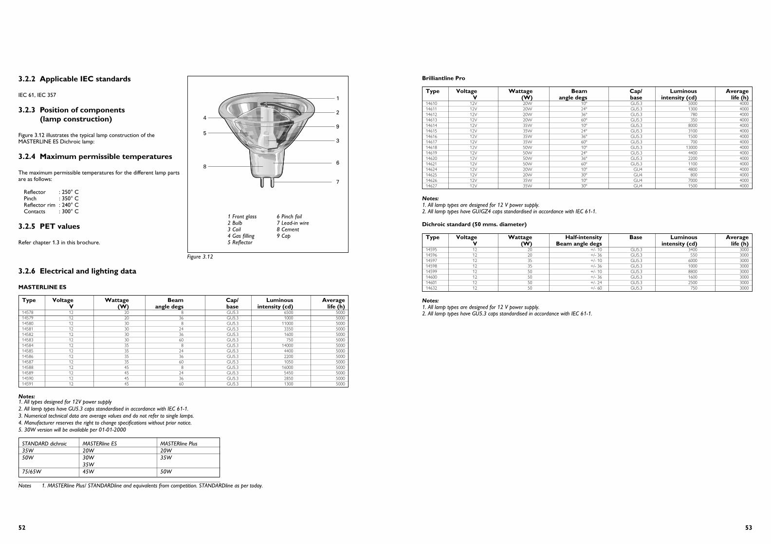
5352
Brilliantline Pro
Type Voltage Wattage Beam Cap/ Luminous AverageV (W) angle degs base intensity (cd) life (h)
14610 12V 20W 10º GU5.3 5000 400014611 12V 20W 24º GU5.3 1300 400014612 12V 20W 36º GU5.3 780 400014613 12V 20W 60º GU5.3 350 400014614 12V 35W 10º GU5.3 8000 400014615 12V 35W 24º GU5.3 3100 400014616 12V 35W 36º GU5.3 1500 400014617 12V 35W 60º GU5.3 700 400014618 12V 50W 10º GU5.3 13000 400014619 12V 50W 24º GU5.3 4400 400014620 12V 50W 36º GU5.3 2200 400014621 12V 50W 60º GU5.3 1100 400014624 12V 20W 10º GU4 4800 400014625 12V 20W 30º GU4 800 400014626 12V 35W 10º GU4 7000 400014627 12V 35W 30º GU4 1500 4000
Notes:1. All lamp types are designed for 12 V power supply.2. All lamp types have GU/GZ4 caps standardised in accordance with IEC 61-1.
Dichroic standard (50 mms. diameter)
Type Voltage Wattage Half-intensity Base Luminous AverageV (W) Beam angle degs intensity (cd) life (h)
14595 12 20 +/- 10 GU5.3 3400 300014596 12 20 +/- 36 GU5.3 550 300014597 12 35 +/- 10 GU5.3 6000 300014598 12 35 +/- 36 GU5.3 1000 300014599 12 50 +/- 10 GU5.3 8800 300014600 12 50 +/- 36 GU5.3 1600 300014601 12 50 +/- 24 GU5.3 2500 300014632 12 50 +/- 60 GU5.3 750 3000
Notes:1. All lamp types are designed for 12 V power supply.2. All lamp types have GU5.3 caps standardised in accordance with IEC 61-1.
3.2.6 Electrical and lighting data
MASTERLINE ES
Type Voltage Wattage Beam Cap/ Luminous AverageV (W) angle degs base intensity (cd) life (h)
14578 12 20 8 GU5.3 6500 500014579 12 20 36 GU5.3 1000 500014580 12 30 8 GU5.3 11000 500014581 12 30 24 GU5.3 3350 500014582 12 30 36 GU5.3 1600 500014583 12 30 60 GU5.3 750 500014584 12 35 8 GU5.3 14000 500014585 12 35 24 GU5.3 4400 500014586 12 35 36 GU5.3 2200 500014587 12 35 60 GU5.3 1050 500014588 12 45 8 GU5.3 16000 500014589 12 45 24 GU5.3 5450 500014590 12 45 36 GU5.3 2850 500014591 12 45 60 GU5.3 1300 5000
Notes:1. All types designed for 12V power supply2. All lamp types have GU5.3 caps standardised in accordance with IEC 61-1.3. Numerical technical data are average values and do not refer to single lamps.4. Manufacturer reserves the right to change specifications without prior notice.5. 30W version will be available per 01-01-2000
STANDARD dichroic MASTERline ES MASTERline Plus 35W 20W 20W50W 30W 35W
35W75/65W 45W 50W
Notes 1. MASTERline Plus/ STANDARDline and equivalents from competition. STANDARDline as per today.
3.2.2 Applicable IEC standards
IEC 61, IEC 357
3.2.3 Position of components (lamp construction)
Figure 3.12 illustrates the typical lamp construction of theMASTERLINE ES Dichroic lamp:
3.2.4 Maximum permissible temperatures
The maximum permissible temperatures for the different lamp partsare as follows:
Reflector : 250° CPinch : 350° CReflector rim : 240° CContacts : 300° C
3.2.5 PET values
Refer chapter 1.3 in this brochure.
1
2
9
3
6
7
5
8
4
Figure 3.12
1 Front glass2 Bulb3 Coil4 Gas filling5 Reflector
6 Pinch foil7 Lead-in wire8 Cement9 Cap

5554
1500
3000
4500
6000
7500
(cd) 0o
180o
30oo30
60oo60
90oo90
120oo120
γ
MASTERline ES 12V 20W 8dgr
(cd) 0o
180o
30oo30
60oo60
90oo90
120oo120
γ
200
400
600
800
1000
MASTERline ES 12V 20W 36dgr
(cd) 0o
180o
30oo30
60oo60
90oo90
120oo120
γ
2500
5000
7500
10000
12500
15000
MASTERline ES 12V 35W 8dgr
(cd) 0o
180o
30oo30
60oo60
90oo90
120oo120
γ
1000
2000
3000
4000
5000
MASTERline ES 12V 35W 24dgr
(cd) 0o
180o
30oo30
60oo60
90oo90
120oo120
500
1000
1500
2000
2500
3000
γ
MASTERline ES 12V 35W 36dgr
(cd) 0o
180o
30oo30
60oo60
90oo90
120oo120
250
500
750
1000
1250
1500
γ
MASTERline ES 12V 35W 60dgr
(cd) 0o
180o
30oo30
60oo60
90oo90
120oo120
2500
5000
7500
10000
12500
15000
γ
MASTERline ES 12V 30W 8dgr
(cd) 0o
180o
30oo30
60oo60
90oo90
120oo120
1000
2000
3000
4000
γ
MASTERline ES 12V 30W 24dgr
(cd) 0o
180o
30oo30
60oo60
90oo90
120oo120
500
1000
1500
2000
γ
MASTERline ES 12V 30W 36dgr
150
300
450
600
750
(cd) 0o
180o
30oo30
60oo60
90oo90
120oo120
γ
MASTERline ES 12V 30W 60dgr
(cd) 0o
180o
30oo30
60oo60
90oo90
120oo120
5000
10000
15000
20000
γ
MASTERline ES 12V 45W 8dgr
(cd) 0o
180o
30oo30
60oo60
90oo90
120oo120
1500
3000
4500
6000
7500
γ
MASTERline ES 12V 45W 24dgr
(cd) 0o
180o
30oo30
60oo60
90oo90
120oo120
500
1000
1500
2000
2500
3000
γ
MASTERline ES 12V 45W 36dgr
(cd) 0o
180o
30oo30
60oo60
90oo90
120oo120
250
500
750
1000
1250
1500
γ
MASTERline ES 12V 45W 60dgr
Photometric data MASTERline ES3.2.7 Lamp dimensions 3.2.8 Photometric data
See figures 3.19 to 3.20 on the next pages.
3.2.9 Spectral distribution
The comparison of the spectral distribution of the STANDARDlinePLUS and ES are given in the diagram in figure 3.17
The typical absolute Irradiance measurements of Masterline ES lampof 12 V 45 W is shown in the curve in figure 3.18
3.2.10 Lamp disposal
Refer chapter 1.6 in this brochure.
3.2.11 Lifetime performance
The typical life expectancy curves for Philips Dichroic lamps aregiven in figure 3.21.
50.0 max.
Ø 1.45 - 1.605.31 ± 0.25
46 m
ax.
38.3
5m
ax.
16.5 max.
9.9
max
.
BRILLIANTline Plus 50 mm
35.3 max.
Ø 0.95 - 1.054 ± 0.25
40 m
ax.
30 max
.
15.2 max.
10.5
m
ax.
50.0 max.
Ø 1.45 - 1.605.33 ± 0.25
46 m
ax.
38.3
5m
ax.
16.6 max.
10.4
max
.
BRILLIANTline Pro 35 mm
16.6 max.
10.4
max
.
Ø 50 max.
Ø 1.45 - 1.605.33 ± 0.25
46 m
ax.
38.3
5m
ax.
Figure 3.14
Figure 3.15
Figure 3.16
Ø 50 max.
Ø 1.45 - 1.605.33 ± 0.25
50.5
max
.
38.3
5m
ax.
16.7 max.
10.5
max
.
Figure 3.13
250 275 300 325 350 375
50
150
250
Wavelength nm
UV-C 280
100
200
0µW
per
5 n
m
UV-B 320 UV-A 380
Figure 3.17
300 400 500 600 650
50
150
250
Wavelength nm
Halogen 12V 50W (at 1m)
100
200
0
µW p
er 5
nm
Figure 3.18
BRILLIANTline Plus
MASTERline ES
MASTERline ES
Dichroic standard
Figure 3.19
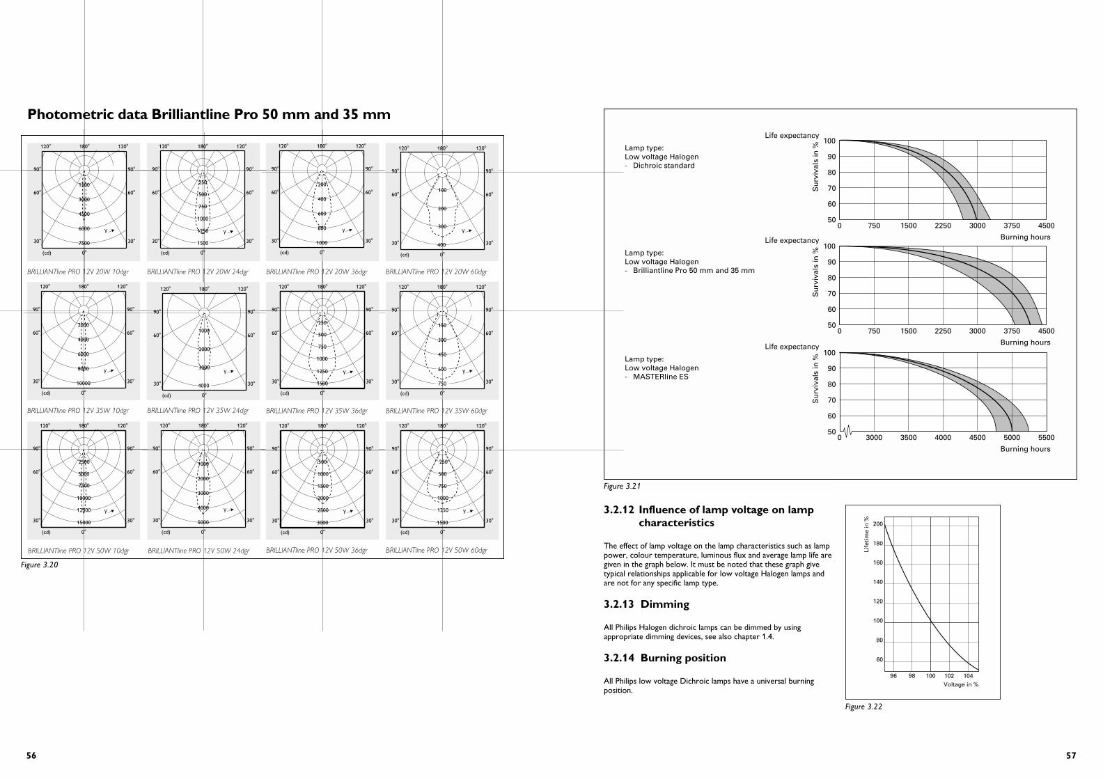
5756
3.2.12 Influence of lamp voltage on lamp characteristics
The effect of lamp voltage on the lamp characteristics such as lamppower, colour temperature, luminous flux and average lamp life aregiven in the graph below. It must be noted that these graph givetypical relationships applicable for low voltage Halogen lamps andare not for any specific lamp type.
3.2.13 Dimming
All Philips Halogen dichroic lamps can be dimmed by usingappropriate dimming devices, see also chapter 1.4.
3.2.14 Burning position
All Philips low voltage Dichroic lamps have a universal burningposition.
Life expectancy
Lamp type:Low voltage Halogen- Dichroic standard
Life expectancy
Lamp type:Low voltage Halogen- MASTERline ES
050
60
70
80
90
100
750 1500 2250 3000 3750 4500
Su
rviv
als
in %
Burning hoursLife expectancy
Lamp type:Low voltage Halogen- Brilliantline Pro 50 mm and 35 mm
050
60
70
80
90
100
750 1500 2250 3000 3750 4500
Su
rviv
als
in %
Burning hours
050
60
70
80
90
100
3000 3500 4000 4500 5000 5500
Su
rviv
als
in %
Burning hours
Figure 3.21
200
180
160
140
120
100
80
60
96 98 100
Life
tim
e in
%
Voltage in %102 104
Figure 3.22
(cd) 0o
180o
30oo30
60oo60
90oo90
120oo120
γ6000
7500
1500
3000
4500
BRILLIANTline PRO 12V 20W 10dgr
(cd) 0o
180o
30oo30
60oo60
90oo90
120oo120
250
500
750
1000
1500
γ1250
BRILLIANTline PRO 12V 20W 24dgr
(cd) 0o
180o
30oo30
60oo60
90oo90
120oo120
γ
15000
2500
5000
7500
10000
12500
BRILLIANTline PRO 12V 50W 10dgr
(cd) 0o
180o
30oo30
60oo60
90oo90
120oo120
γ
1000
2000
3000
4000
5000
BRILLIANTline PRO 12V 50W 24dgr
(cd) 0o
180o
30oo30
60oo60
90oo90
120oo120
γ
500
1000
1500
2500
3000
2000
BRILLIANTline PRO 12V 50W 36dgr
(cd) 0o
180o
30oo30
60oo60
90oo90
120oo120
γ
250
500
750
1000
1250
1500
BRILLIANTline PRO 12V 50W 60dgr
(cd) 0o
180o
30oo30
60oo60
90oo90
120oo120
γ
10000
2000
4000
6000
8000
BRILLIANTline PRO 12V 35W 10dgr
2000
4000
(cd) 0o
180o
30oo30
60oo60
90oo90
120oo120
γ
1000
3000
BRILLIANTline PRO 12V 35W 24dgr
(cd) 0o
180o
30oo30
60oo60
90oo90
120oo120
γ
250
500
750
1000
1250
1500
BRILLIANTline PRO 12V 35W 36dgr
(cd) 0o
180o
30oo30
60oo60
90oo90
120oo120
γ
150
300
450
600
750
BRILLIANTline PRO 12V 35W 60dgr
(cd) 0o
180o
30oo30
60oo60
90oo90
120oo120
γ
1000
200
400
600
800
BRILLIANTline PRO 12V 20W 36dgr
100
200
300
400
(cd) 0o
180o
30oo30
60oo60
90oo90
120oo120
γ
BRILLIANTline PRO 12V 20W 60dgr
Photometric data Brilliantline Pro 50 mm and 35 mm
Figure 3.20

59
3.3.1 Introduction and description
Halogen reflector lamps with a special "cool daylight" colourimpression. This lamp further consists of an extra-low-voltagehalogen burner optically positioned in a glass reflector which has aspecial heat-transmitting and light-reflecting dichroic coating.This combination of the burner and the reflector results in a high-intensity beam with a clearly defined beam spread. The dichroiccool beam reflector coating transmits the infrared radiation (heat)backwards through the glass and reflects the visible radiation (light)forward, thus resulting in a cool daylight beam impression.
FeaturesThe most important features of the Diamondline Pro lamp rangeare:- a high-pressure Xenon gas filled burner- axial filament optimally aligned in a reflector with hard dichroic
coating providing constant high quality, durability, maintenanceover lifetime and aesthetics.
- with front glass- average lifetime of 4000 hrs.- range of 35 W and 50 W 50 mm types.- colour temperature of 4100 K- excellent colour rendering (Ra = 100)- GU5.3 base: extra retention in luminaire- universal burning position- dimmable
ApplicationsDiamondline Pro lamps are ideally suitable for accent, task anddecorative lighting in jewelry shops (diamonds, silver, gold, cristal).
3.3.2 Applicable IEC standards
Diamondline Pro is produced according to IEC 357.
3.3.3 Maximum permissible temperatures
Reflector : 250ºCPinch : 350ºCReflector mm: 240ºCContacts : 300ºC
3.3.4 PET values
Refer to chapter 1.3
3.3.5 Lamp dimensions
3.3.6 Electrical and lighting data
Type V W Beam Cap/base ANSI Max. Lampangle code luminous life
intensity 50%cd h
14656 12V 35W 10º GU5.3 FRB 5400 400014658 12V 35W 24º GU5.3 FRA 1700 400014659 12V 35W 36º GU5.3 FMW 1000 400014668 12V 50W 10º GU5.3 EXT 6400 400014670 12V 50W 24º GU5.3 EXZ 2700 400014671 12V 50W 36º GU5.3 EXN 1200 4000
3.3.7 Photometric data
Refer to page 59.
3.3.8 Lamp disposal
Refer to chapter 1.6 in this brochure.
3.3.9 Lifetime performance
Typical life expectancy curves for Diamondline Pro are given below.
3.3 - Low-voltage dichroic reflector Diamondline Pro
58
∅ 50 max.
∅ 1.45 - 1.605.33 ± 0.25
46 m
ax.
38.3
5m
ax.
16.6 max.
10.4
max
.
Diamondline Pro (50 mm) GU5.3
Figure 3.23
050
60
70
80
90
100
750 1500 2250 3000 3750 4500
Su
rviv
als
in %
Burning hours
Brilliantline Pro 50 mm and 35 mm
Figure 3.24
Diamondline 35W (TEMP) 24D
aachen3524
Polar intensity diagram
(cd) 0o
180o
30oo30
60oo60
90oo90
120oo120
500
1000
1500
2000
γ
Visual impact diagram
Acc
ent
fact
or
2
5
1015
30
50
100
Eh(lx)25 50 100 250 500 1000
4m3m
2m
1m
Beam diagram
hh(m)
(m) (lx) VBA1/2Imax
E0 d(m)
K4
1.0
2.0
3.0
4.0
5.03.0 2.0 1.0 0.0 1.0 2.0 3.0 (m)
1.0 1738 0.73 0.43
1.5 772 1.09 0.64
2.0 434 1.46 0.85
2.5 278 1.82 1.06
3.0 193 2.18 1.28
3.5 142 2.55 1.49
4.0 109 2.91 1.70
4.5 86 3.28 1.91
o2 x 12maxI2/1VBA 2 x 20o
Diamondline 35W (TEMP) SPOT
aachen35sp
Polar intensity diagram
(cd) 0o
180o
30oo30
60oo60
90oo90
120oo120
1500
3000
4500
6000
7500
γ
Visual impact diagram
Acc
ent
fact
or
2
5
1015
30
50
100
Eh(lx)25 50 100 250 500 1000
4m3m
2m
1m
Beam diagram
hh(m)
(m) (lx) VBA1/2Imax
E0 d(m)
K4
1.0
2.0
3.0
4.0
5.03.0 2.0 1.0 0.0 1.0 2.0 3.0 (m)
1.0 5436 0.28 0.17
1.5 2416 0.42 0.26
2.0 1359 0.56 0.35
2.5 870 0.70 0.44
3.0 604 0.84 0.52
3.5 444 0.98 0.61
4.0 340 1.12 0.70
4.5 268 1.26 0.79
o2 x 5maxI2/1VBA 2 x 8o
Diamondline 50W (TEMP) 24D
aachen5024
Polar intensity diagram
(cd) 0o
180o
30oo30
60oo60
90oo90
120oo120
500
1000
1500
2000
2500
3000
γ
Visual impact diagram
Acc
ent
fact
or
2
5
1015
30
50
100
Eh(lx)25 50 100 250 500 1000
4m3m
2m
1m
Beam diagram
hh(m)
(m) (lx) VBA1/2Imax
E0 d(m)
K4
1.0
2.0
3.0
4.0
5.03.0 2.0 1.0 0.0 1.0 2.0 3.0 (m)
1.0 2701 0.73 0.39
1.5 1200 1.09 0.58
2.0 675 1.46 0.78
2.5 432 1.82 0.97
3.0 300 2.18 1.17
3.5 220 2.55 1.36
4.0 169 2.91 1.56
4.5 133 3.28 1.75
o2 x 11maxI2/1VBA 2 x 20o
Diamondline 50W 36D
aachen5036
Polar intensity diagram
(cd) 0o
180o
30oo30
60oo60
90oo90
120oo120
250
500
750
1000
1250
1500
γ
Visual impact diagram
Acc
ent
fact
or
2
5
1015
30
50
100
Eh(lx)25 50 100 250 500 1000
4m3m
2m
1m
Beam diagram
hh(m)
(m) (lx) VBA1/2Imax
E0 d(m)
K4
1.0
2.0
3.0
4.0
5.03.0 2.0 1.0 0.0 1.0 2.0 3.0 (m)
1.0 1211 1.15 0.69
1.5 538 1.73 1.03
2.0 303 2.31 1.38
2.5 194 2.89 1.72
3.0 135 3.46 2.07
3.5 99 4.04 2.41
4.0 76 4.62 2.75
4.5 60 5.20 3.10
o2 x 19maxI2/1VBA 2 x 30o
Diamondline 50W (TEMP) SPOT
aachen50sp
Polar intensity diagram
(cd) 0o
180o
30oo30
60oo60
90oo90
120oo120
1500
3000
4500
6000
7500
γ
Visual impact diagram
Acc
ent
fact
or
2
5
1015
30
50
100
Eh(lx)25 50 100 250 500 1000
4m3m
2m
1m
Beam diagram
hh(m)
(m) (lx) VBA1/2Imax
E0 d(m)
K4
1.0
2.0
3.0
4.0
5.03.0 2.0 1.0 0.0 1.0 2.0 3.0 (m)
1.0 6405 0.28 0.17
1.5 2847 0.42 0.26
2.0 1601 0.56 0.35
2.5 1025 0.70 0.44
3.0 712 0.84 0.52
3.5 523 0.98 0.61
4.0 400 1.12 0.70
4.5 316 1.26 0.79
o2 x 5maxI2/1VBA 2 x 8o

6160
3.4.5 Electrical and lighting data
Aluminium reflector lamps with clear front glass
Type Voltage Wattage Beam Lamp diameter Luminous(V) (W) angle(°) (mm) intensity (cd)
6425 6 15 4 56 120006424 6 15 6 37 62006426 6 15 14 56 14006433 12 20 6 37 70006434 12 20 18 37 15006435 12 20 32 37 7506429 6 35 6 56 180006430 6 35 14 56 40006465 12 50 6 56 210006438 12 50 10 56 130006439 12 50 25 56 2500
Aluminium reflector lamps with frosted front glass
Type Voltage Wattage Beam Lamp diameter Luminous(V) (W) angle (°) (mm) intensity (cd)
6434/FR 12 20 18 37 10006435/FR 12 20 32 37 4006439/FR 12 50 25 56 1900
Note for lamps with clear or frosted front glass:All lamps have B15d caps in accordance with IE
3.4.6 Lamp dimensions
3.4.7 Photometric data
See figure 3.27 and 3.28.
∅ 37 ± 1
38±
3
∅ 56 ± 2
57±
3
Figure 3.26
3.4 - Aluminium reflector lamps
3.4.3 Maximum permissible temperatures
The maximum permissible temperatures for different parts of thelamps are as given below:
Reflector : 450° CFront glass : 250° CPinch : 350° CContacts : 220° C
3.4.4 PET values
Refer chapter 1.3 in this brochure.
Spectral distributionThe typical spectral distribution of an Aluminium reflector lamp isgiven in figure 3.22 along with that of a typical Dichroic reflectorlamp for comparison purposes. The spectral irradiance distribution for a 6 V 35 W lamp with 14beam spread is given in figure 3.25 below.
300 400 500 600 700
100
300
500Halogen 6V, 35W
nm
200
400
0
µW p
er 5
nm
Figure 3.25
3.4.1 Introduction and description
Closed reflector lamps consisting of a Halogen extra low voltagecapsule precisely positioned (photo-electrically) in a parabolicaluminium reflector. The lamps have an integrated front glass coverwhich is flat and may be clear or frosted.
Features and Benefits
Benefits Features
All benefits of Halogen lampsMore light • higher luminous efficacyPure, bright light • colour temp. 3000° KExcellent colour rendering • Ra=100Longer lamp life • 2000/4000 burning hoursConstant light output • no bulb blackeningover life
High accent factors • high intensities
No soiling of reflector • flat, clear/frostedNo damage/touching front glassof the burnerAlmost no UV output Almost no colour fading
Quick, simple, secure installation • B15d bayonet lamp cap
Longer luminaire/holder life • less heat at the backof lamp
No undesirable light patches • no light at the backon ceiling of the lamp
No undue heating of ceiling • very low heat emittedat the back of the lamp
The aluminium reflector lamps are available in 56 mms. and 37mms. diameter (37 mms. are suitable where installation space isless). These lamps are available in clear and frosted front glassversions as indicated subsequently in the text (refer” Lampdimensions” and “Lamp data - electrical and lighting”).
ApplicationsAluminium reflector lamps are ideally suited for the followingapplications:• spotlighting of merchandise• display lighting for museums and exhibitions• accent lighting in homes, restaurants and bars• tasklighting for precision work (watchmaking, jewellery)
and reading• in applications where heat and light is not desired at the back of
the lamp
3.4.2 Applicable IEC standards
The applicable IEC standards for Aluminium reflector lamps are:
IEC 61, IEC 357

6362
1
2
3
0° 30°
0
1600
60°
90°
180°
h d Emax(m) (m) (lux)
6426 6V 15W 14° B15D
0.43 1400
0.85 350
1.28 155
K 4
cd LVA20609
Acc
ent F
acto
r
50 100 250 500 1000 250025
2
5
1015
30
50
100
General lighting level (lux)
3m
1m
2m
Imax = 1400cd VBA = 2 x 12°
1
2
3
0° 30°
0
1600
0
60°
90°
180°
h d Emax(m) (m) (lux)
6425 6V 15W 4° B15D
0.16 12000
0.31 3000
0.47 1333
K 3
cd LVA20607
Acc
ent F
acto
r
50 100 250 500 1000 250025
2
5
1015
30
50
100
General lighting level (lux)
3m
1m
2m
Imax = 12000cd VBA = 2 x 4.5°
cd LVA 20628
1
2
3
0° 30°
0
6400
60°
90°
180°
h d Emax(m) (m) (lux)
6430 6V 35W 14° B15D
0.54 4400
1.07 1100
1.61 489
K 4
Acc
ent F
acto
r
50 100 250 500 1000 250025
2
5
1015
30
50
100
General lighting level (lux)
3m
1m
2m
Imax = 4400cd VBA = 2 x 15°
1
2
3
0° 30°
0
2560
0
60°
90°
180°
h d Emax(m) (m) (lux)
6429 6V 35W 6° B15D
0.21 18000
0.42 4500
0.63 2000
K 3
cd LVA20547
Acc
ent F
acto
r
50 100 250 500 1000 250025
2
5
1015
30
50
100
General lighting level (lux)
3m
1m
2m
Imax = 18000cd VBA = 2 x 6°
Figure 3.27
1
2
3
0° 30°
0
9600
60°
90°
180°
h d Emax(m) (m) (lux)
K 3
6424 6V 15W 6° B15D
0.30 6200
0.60 1550
0.90 688
cd
Acc
ent F
acto
r
50 100 250 500 1000 250025
2
5
1015
30
50
100
General lighting level (lux)LVA20651
3m
1m
2m
Imax = 6200cd VBA = 2 x 8.5°
1
2
3
0° 30°
0
9600
60°
90°
180°
h d Emax(m) (m) (lux)
6433 12V 20W 6° B15D
0.18 7000
0.35 1750
0.52 777
K 3
cd LVA20603
Acc
ent F
acto
r
50 100 250 500 1000 250025
2
5
1015
30
50
100
General lighting level (lux)
3m
1m
2m
Imax = 7000cd VBA = 2 x 5°
1
2
3
0° 30°
0
1600
60°
90°
180°
h d Emax(m) (m) (lux)
6434 12V 20W 18° B15D
0.69 1500
1.38 375
2.07 166
K 4
cd LVA20620
Acc
ent F
acto
r
50 100 250 500 1000 250025
2
5
1015
30
50
100
General lighting level (lux)
3m
1m
2m
Imax = 1500cd VBA = 2 x 19°
1
2
3
0° 30°
0
800
60°
90°
180°
h d Emax(m) (m) (lux)
6435 12V 20W 32° B15D
0.79 750
1.58 187
2.37 83
K 4
cd LVA20604
Acc
ent F
acto
r
50 100 250 500 1000 250025
2
5
1015
30
50
100
General lighting level (lux)
3m
1m
2m
Imax = 750cd VBA = 2 x 21.5°
Figure 3.28
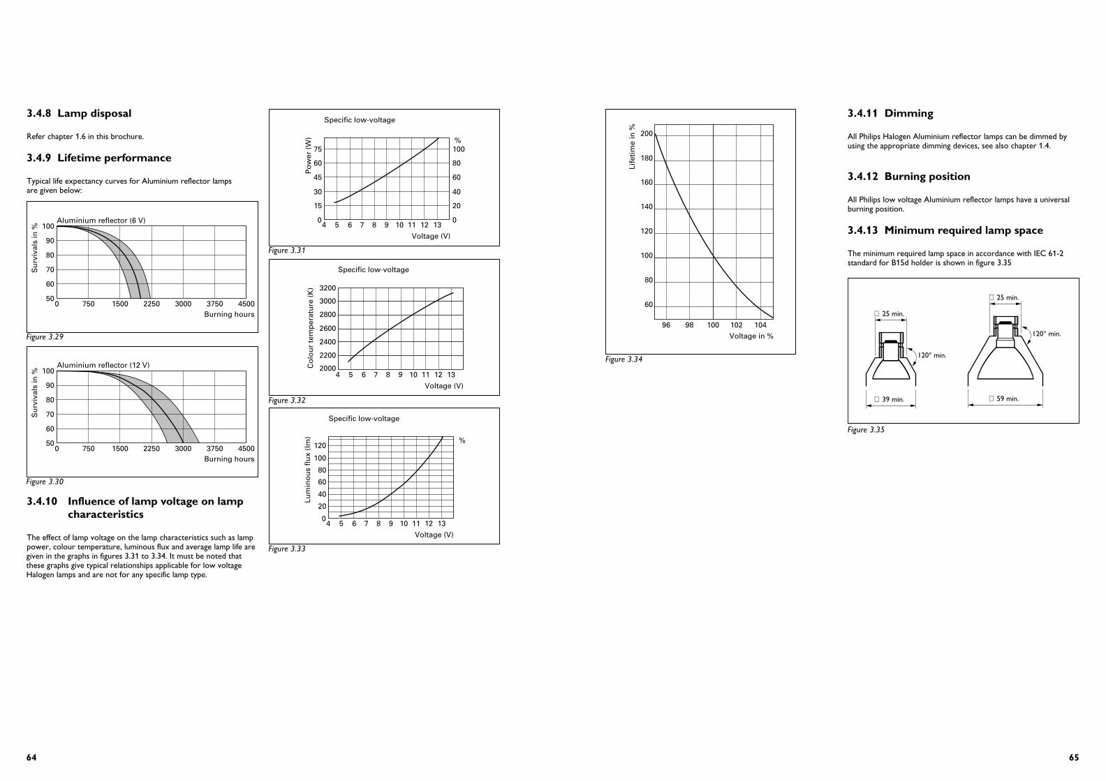
6564
3.4.11 Dimming
All Philips Halogen Aluminium reflector lamps can be dimmed byusing the appropriate dimming devices, see also chapter 1.4.
3.4.12 Burning position
All Philips low voltage Aluminium reflector lamps have a universalburning position.
3.4.13 Minimum required lamp space
The minimum required lamp space in accordance with IEC 61-2standard for B15d holder is shown in figure 3.35
∅ 59 min.
∅ 25 min.
120° min.
∅ 39 min.
∅ 25 min.
120° min.
Figure 3.35
200
180
160
140
120
100
80
60
96 98 100
Life
tim
e in
%
Voltage in %102 104
Figure 3.34
3.4.8 Lamp disposal
Refer chapter 1.6 in this brochure.
3.4.9 Lifetime performance
Typical life expectancy curves for Aluminium reflector lamps are given below:
3.4.10 Influence of lamp voltage on lampcharacteristics
The effect of lamp voltage on the lamp characteristics such as lamppower, colour temperature, luminous flux and average lamp life aregiven in the graphs in figures 3.31 to 3.34. It must be noted thatthese graphs give typical relationships applicable for low voltageHalogen lamps and are not for any specific lamp type.
050
60
70
80
90
100Aluminium reflector (6 V)
750 1500 2250 3000 3750 4500
Su
rviv
als
in %
Burning hours
050
60
70
80
90
100Aluminium reflector (12 V)
750 1500 2250 3000 3750 4500
Su
rviv
als
in %
Burning hours
Figure 3.29
Figure 3.30
Specific low-voltage
Voltage (V)
Po
wer
(W
) %75
60
45
30
15
04 5 6 7 8 9 10 11 12 13
100
80
60
40
20
0
Specific low-voltage
Voltage (V)
Co
lou
r te
mp
erat
ure
(K
) 3200
3000
2800
2600
2400
2200
20004 5 6 7 8 9 10 11 12 13
Specific low-voltage
Voltage (V)
Lum
ino
us
flu
x (l
m) %
100
120
80
60
40
20
04 5 6 7 8 9 10 11 12 13
Figure 3.31
Figure 3.32
Figure 3.33
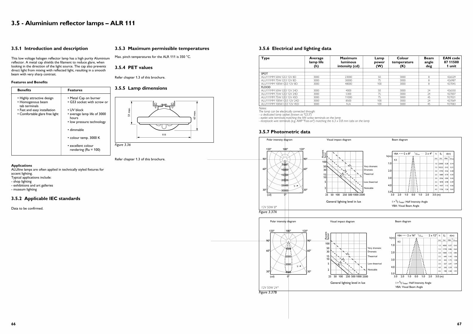
6766
3.5.6 Electrical and lighting data
3.5.7 Photometric data
Type Average Maximum Lamp Colour Beam EAN codelamp life luminous power temperature angle 87 11500
(h) intensity (cd) (W) (K) deg 1 unit
SPOTALU111MM 50W G53 12V 8D 3000 23000 50 3000 8 426529ALU111MM 75W G53 12V 8D 3000 30000 75 3000 8 426987ALU111MM 100W G53 12V 8D 3000 48000 100 3000 8 427045FLOODALU111MM 50W G53 12V 24D 3000 4000 50 3000 24 426550ALU111MM 75W G53 12V 24D 3000 5300 75 3000 24 427007ALU111MM 75W G53 12V 45D 3000 11000 75 3000 45 927021ALU111MM 100W G53 12V 24D 3000 8500 100 3000 24 427069ALU111MM 100W G53 12V 45D 3000 N.A 100 3000 45 927083
Notes: The lamp can be electrically connected through: - a dedicated lamp socket (known as "G53")- eyelet wire terminals matching the M4 screw terminals on the lamp- receptacle wire terminals (e.g. AMP "Fast-on") matching the 6.3 x 0.8 mm tabs on the lamp
Polar intensity diagram
(cd) 0º
180º
30º30º
60º60º
90º90º
120º120º
5000
10000
15000
20000
25000
30000
γ
Visual impact diagram
Acc
ent
fact
or
2
5
1015
3050
100
25 50 100 250 500 1000
4m3m
2m
1m
Beam diagram
hh(m)
(m) (lx) VBA1/2Imax
E0 d(m)
K3
1.0
2.0
3.0
4.0
5.03.0 2.0 1.0 0.0 1.0 2.0 3.0 (m)
1.0 23000 0.28 0.14
1.5 10222 0.42 0.21
2.0 5750 0.56 0.28
2.5 3680 0.70 0.35
3.0 2556 0.84 0.42
3.5 1878 0.98 0.49
4.0 1437 1.12 0.56
4.5 1136 1.26 0.63
2 x 4ºmaxI2/1VBA 2 x 8º
Very dramatic
Dramatic
Theatrical
Low theatrical
2500
General lighting level in lux
Noticable
max/1 2 l : Half Intensity Angle
VBA: Visual Beam Angle
I >
3.5.1 Introduction and description
This low voltage halogen reflector lamp has a high purity Aluminiumreflector. A metal cap shields the filament to reduce glare, whenlooking in the direction of the light source. The cap also preventsdirect light from mixing with reflected light, resulting in a smoothbeam with very sharp contrast.
Features and Benefits
Benefits Features
• Highly attractive design • Metal Cap on burner• Homogenous beam • G53 socket with screw or
tab terminals• Fast and easy installation • UV block• Comfortable glare free light • average lamp life of 3000
hours• low pressure technology
• dimmable
• colour temp. 3000 K
• excellent colourrendering (Ra = 100)
ApplicationsALUline lamps are often applied in technically styled fixtures foraccent lighting. Typical applications include: - shop lighting- exhibitions and art galleries- museum lighting
3.5.2 Applicable IEC standards
Data to be confirmed.
3.5.3 Maximum permissible temperatures
Max. pinch temperatures for the ALR 111 is 350 °C.
3.5.4 PET values
Refer chapter 1.3 of this brochure.
3.5.5 Lamp dimensions
Refer chapter 1.3 of this brochure.
3.5 - Aluminium reflector lamps – ALR 111
111
63 m
ax.
51 m
ax.
Figure 3.36
12V 50W 8°
Figure 3.37A
Polar intensity diagram
(cd) 0º
180º
30º30º
60º60º
90º90º
120º120º
Visual impact diagram
Acc
ent
fact
or
2
5
1015
3050
100
25 50 100 250 500 1000
Beam diagram
h(m)
1.0
2.0
3.0
4.0
5.03.0 2.0 1.0 0.0 1.0 2.0 3.0 (m)
1000
2000
3000
4000
γ4m
3m
2m
1m
h
(m) (lx) VBA1/2Imax
E0 d(m)
K3
1.0 4000 0.57 0.43
1.5 1778 0.86 0.64
2.0 1000 1.15 0.85
2.5 640 1.43 1.06
3.0 444 1.72 1.28
3.5 327 2.01 1.49
4.0 250 2.29 1.70
4.5 198 2.58 1.91
2 x 12ºmaxI2/1VBA 2 x 16º
2500
Very dramatic
Dramatic
Theatrical
Low theatrical
General lighting level in lux
Noticable
max/1 2 l : Half Intensity Angle
VBA: Visual Beam Angle
I >
12V 50W 24°
Figure 3.37B

6968
3.5.8 Lamp disposal
Refer to chapter 1.6 in this brochure.
3.5.9 Lifetime performance
Typical life expectancy curves for Aluminium reflector lamps are given below:
Polar intensity diagram
(cd) 0º
180º
30º30º
60º60º
90º90º
120º120º
10000
20000
30000
40000
50000
60000
γ
Visual impact diagram
Acc
ent
fact
or
2
5
1015
3050
100
25 50 100 250 500 1000
4m3m
2m
1m
Beam diagram
Very dramatic
Dramatic
Theatrical
Low theatrical
2500
General lighting level in lux
Noticable
hh(m)
(m) (lx) VBA1/2Imax
E0 d(m)
K3
1.0
2.0
3.0
4.0
5.03.0 2.0 1.0 0.0 1.0 2.0 3.0 (m)
1.048000 0.43 0.14
1.521333 0.64 0.21
2.0 12000 0.85 0.28
2.5 7680 1.06 0.35
3.0 5333 1.28 0.42
3.5 3918 1.49 0.49
4.0 3000 1.70 0.56
4.5 2370 1.91 0.63
2 x 4ºmaxI2/1VBA 2 x 12º
max/1 2 l : Half Intensity Angle
VBA: Visual Beam Angle
I >
Polar intensity diagram
(cd) 0º
180º
30º30º
60º60º
90º90º
120º120º
10000
12000
γ
Visual impact diagram
Acc
ent
fact
or
2
5
1015
3050
100
25 50 100 250 500 1000
4m3m
2m
1m
Beam diagram
hh(m)
(m) (lx) VBA1/2Imax
E0 d(m)
K3
1.0
2.0
3.0
4.0
5.03.0 2.0 1.0 0.0 1.0 2.0 3.0 (m)
1.0 8500 0.69 0.43
1.5 3778 1.03 0.64
2.0 2125 1.38 0.85
2.5 1360 1.72 1.06
3.0 944 2.07 1.28
3.5 694 2.41 1.49
4.0 531 2.75 1.70
4.5 420 3.10 1.91
2 x 12ºmaxI2/1VBA 2 x 19º
Very dramatic
Dramatic
Theatrical
Low theatrical
2500
max/1 2 l : Half Intensity Angle
VBA: Visual Beam Angle
General lighting level in lux
Noticable
2000
4000
6000
8000
I >
Polar intensity diagram
(cd) 0º
180º
30º30º
60º60º
90º90º
120º120º
5000
10000
15000
20000
25000
30000
γ
Visual impact diagram
Acc
ent
fact
or
2
5
1015
3050
100
25 50 100 250 500 1000
4m3m
2m
1m
Beam diagram
hh(m)
(m) (lx) VBA1/2Imax
E0 d(m)
K3
1.0
2.0
3.0
4.0
5.03.0 2.0 1.0 0.0 1.0 2.0 3.0 (m)
1.0 30000 0.43 0.14
1.5 13333 0.64 0.21
2.0 7500 0.85 0.28
2.5 4800 1.06 0.35
3.0 3333 1.28 0.42
3.5 2449 1.49 0.49
4.0 1875 1.70 0.56
4.5 1481 1.91 0.63
2 x 4ºmaxI2/1VBA 2 x 12º
Very dramatic
Dramatic
Theatrical
Low theatrical
2500
General lighting level in lux
Noticable
max/1 2 l : Half Intensity Angle
VBA: Visual Beam Angle
I >
Polar intensity diagram
(cd) 0º
180º
30º30º
60º60º
90º90º
120º120º
1000
2000
3000
4000
5000
6000
γ
Visual impact diagram
Acc
ent
fact
or
2
5
1015
3050
100
25 50 100 250 500 1000
4m3m
2m
1m
Beam diagram
hh(m)
(m) (lx) VBA1/2Imax
E0 d(m)
K3
1.0
2.0
3.0
4.0
5.03.0 2.0 1.0 0.0 1.0 2.0 3.0 (m)
1.0 5300 0.65 0.43
1.5 2356 0.97 0.64
2.0 1325 1.30 0.85
2.5 848 1.62 1.06
3.0 589 1.95 1.28
3.5 433 2.27 1.49
4.0 331 2.60 1.70
4.5 262 2.92 1.91
2 x 12ºmaxI2/1VBA 2 x 18º
Very dramatic
Dramatic
Theatrical
Low theatrical
2500
General lighting level in lux
Noticable
max/1 2 l : Half Intensity Angle
VBA: Visual Beam Angle
I >
12V 75W 24°
Figure 3.37C
12V 75W 45°
Figure 3.37D
12V 75W 8°
Figure 3.37E
12V 100W 8°
Figure 3.37F
050
60
70
80
90
100Aluminium reflector (12 V)
750 1500 2250 3000 3750 4500
Su
rviv
als
in %
Burning hours
Figure 3.38


