

1
Polar Class RulesOverview
April 2014 – Claude Daley
Claude DaleyProfessor
Memorial University
St. John’s, CANADA
April 2014
2
Outline
Main ice class rules and areas of application
IACS Polar Class Unified Requirements
• Technical Background
• Ice load model
• Class factors
• Plating strength
• Framing strength
• Materials
• Longitudinal strength
Equivalency Issues Brazilian Research Vessel Mar Sem Fim, sunk by ice pressure, April 2012, Antarctica,Source: sometimes-interesting.com

3
Ice Class Areas
Ice Class Rules have
evolved from:
Government Policy
and
Classification Society
Response to Clients

4
IACS Polar Class Unified Requirements (UR)
I1: Polar Class Descriptions and Application
I2: Structural Requirements for Polar Class Ships
I3: Machinery Requirements for Polar Class Ships
Download available from IACS web site www.IACS.org.uk

5
Lowest Polar Class (PC7): should have general levels of
strengthening roughly comparable to Baltic 1A
Highest Polar Class (PC1): capable of independent operation
without limitations
The Polar Rules provide a minimum level of ice strengthening. All
Polar Classes can encounter ice conditions that could damage the
structure
Class selection is a balance among
ice conditions, operational
requirements, and cost
Polar Classes

6
Major Parts of IACS Polar Class: UR I2
Hull Areas (I2.2)
Design Ice Loads (I2.3)
Shell Plate Requirements (I2.4)
Frame Requirements (I2.5 - I2.9)
• Transversely-framed
• Longitudinally-framed
• Structural stability

7
Example of Hull Area Extents
Shell expansion
8
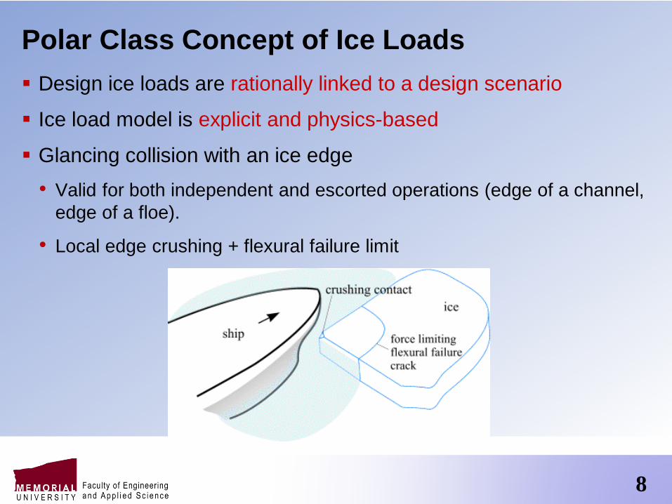
Polar Class Concept of Ice Loads
Design ice loads are rationally linked to a design scenario
Ice load model is explicit and physics-based
Glancing collision with an ice edge
• Valid for both independent and escorted operations (edge of a channel,
edge of a floe).
• Local edge crushing + flexural failure limit

9
Polar Class Concept of Ice Loads
The load equation is derived from the solution of a Ship-Ice
Collision Model
• Normal Kinetic Energy = Ice Indentation Energy
• Find indentation Find force, area, pressure
Model considers ice thickness, ice strength, hull form, ship size
and ship speed
icenormal IEKE
10
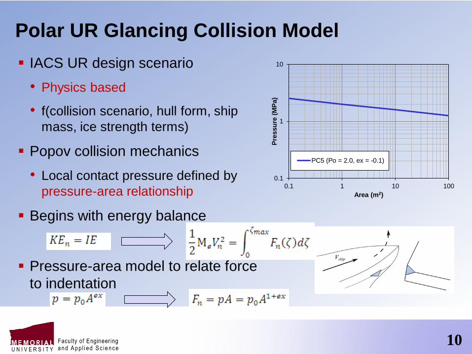
Polar UR Glancing Collision Model
IACS UR design scenario
• Physics based
• f(collision scenario, hull form, ship
mass, ice strength terms)
Popov collision mechanics
• Local contact pressure defined by
pressure-area relationship
Begins with energy balance
Pressure-area model to relate force
to indentation
0.1
1
10
0.1 1 10 100
Pre
ssu
re (
MP
a)
Area (m2)
PC5 (Po = 2.0, ex = -0.1)

11
Indentation Geometry (RHS of Equation)
Wedge ice edge geometry
Contact zoned idealized to
rectangular patch

12
Ice Load Derivation
Normal force exact solution
Simplified with several assumptions
• Families of icebreaking hull forms
• Mass reduction coefficient simplified
Rule Formulation

13
Pure crushing solution
Simplified formulation
• One for crushing
• One for flexural failure
• Limit to 0.6
Shape Factor, fa

14
Rule Formulations
Other rule formulations
• Pressure
• Line load
• Width
• Height
15
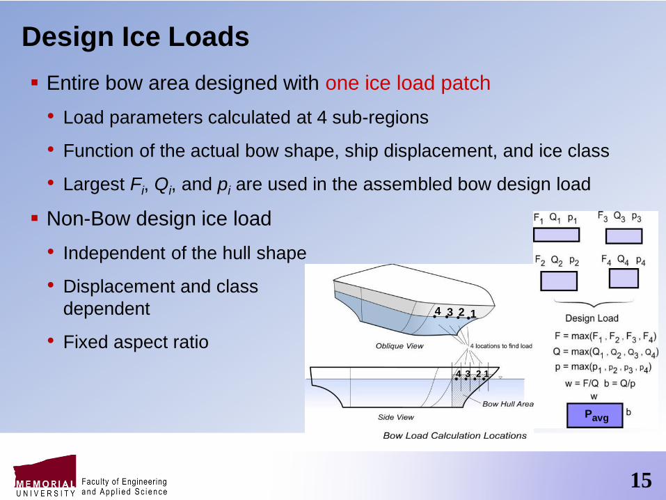
Pavg
Design Ice Loads
Entire bow area designed with one ice load patch
• Load parameters calculated at 4 sub-regions
• Function of the actual bow shape, ship displacement, and ice class
• Largest Fi, Qi, and pi are used in the assembled bow design load
Non-Bow design ice load
• Independent of the hull shape
• Displacement and class
dependent
• Fixed aspect ratio
1234
1234
16
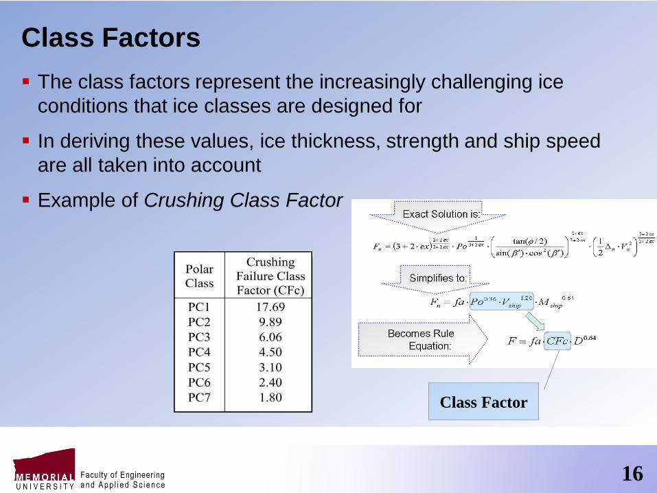
Class Factors
The class factors represent the increasingly challenging ice
conditions that ice classes are designed for
In deriving these values, ice thickness, strength and ship speed
are all taken into account
Example of Crushing Class Factor
Class Factor

17
Class Factors
Calibrated to align strength levels with service experience

18
Hull Area Factors (Non-bow)
The areas other than the bow are designed for a portion of the bow
load
The hull areas are defined based on the shape and waterlines of
the vessel
19
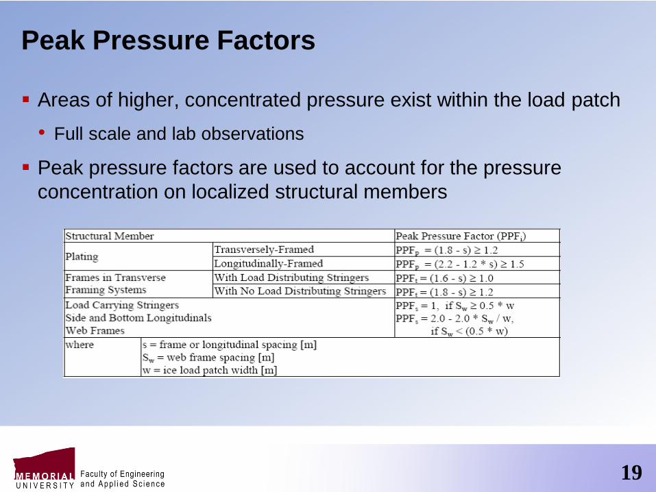
Peak Pressure Factors
Areas of higher, concentrated pressure exist within the load patch
• Full scale and lab observations
Peak pressure factors are used to account for the pressure
concentration on localized structural members

20
Structural Strength
Design philosophy: realistic plastic response
• Derived from analytical (energy based) solutions
• Verified by extensive FEA and lab experiments
Plastic design
• design to resist normal and extreme ice load
levels
• Considerable strength reserve
• Relatively long return period for design loadsFrame Capacity Experiments
Source: Memorial University

21
Plastic Section Modulus
Plastic Section Modulus
• 1st moment of area about the plastic neutral axis (PNA)
• PNA is located at the half-area axis, typically assumed at intersection of
web and shell
• Generally 1.25~1.35 x elastic modulus
Plastic NA
-100
100
300
500
700
900
-100 100 300 500 700 900
Typical frame attached
to plating of ship

22
Plating Strength
Plate folding based on perfectly plastic hinge formation
• Gives nominal plastic capacity (>2 x yield)
• Small plastic strains (shown by FE analysis)
• Substantial membrane & material reserve (little chance of rupture)
"Net scantling" approach
• t = tnet + ts
Framing orientation
• Transversely framed
• Longitudinally framed
• Obliquely framed

23
Framing Strength
Framing members
• Local frames - longitudinal or vertical stiffeners
• Load carrying stringers*
• Web frames*
Local frames
• Required net shear area
• Required net plastic section
modulus
Stringers and web frames
• Scantlings are per class rules
• Structural stability (buckling)
checks
Intermediate
stringer*
Main frames
(stiffeners)
Stringers*
Plating
Web frames*

24
Framing Strength
3 limit-states (allowable loads) checked
• Two involve shear/bending resulting in interaction effects
• Third is pure shear

25
Framing Strength
Frame design allows tradeoffs
• Over-capacity in web area allows
saving in modulus
• Design point is post-yield, but still
quasi-elastic
• Permanent deflections are ~0, with
significant strength reserve

26
Framing Strength
Design point is onset of permanent deflections

27
Framing Requirements
Required net shear area and plastic modulus
• Transversely framed arrangements
• Longitudinally framed arrangements

28
Stability Checks
Frames subjected to compressive loading can be susceptible to
buckling
• Web depth ratios (simple slenderness limits)
• Stiffened panels
• Flange width wf > 5 x tw

29
Material Selection
Fracture toughness of steel in low temperature environments is of
concern
Steel grade requirements provided considering the required
fracture toughness / ductility

30
Longitudinal Strength
Scenario: head-on ramming
Ice induced bending moment and shear forces combined with still
water loads (waves ignored) to assess
hull girder strength
Parameters to be considered
• Design vertical ice force at the bow
• Design vertical shear force
• Design vertical ice bending moment
31
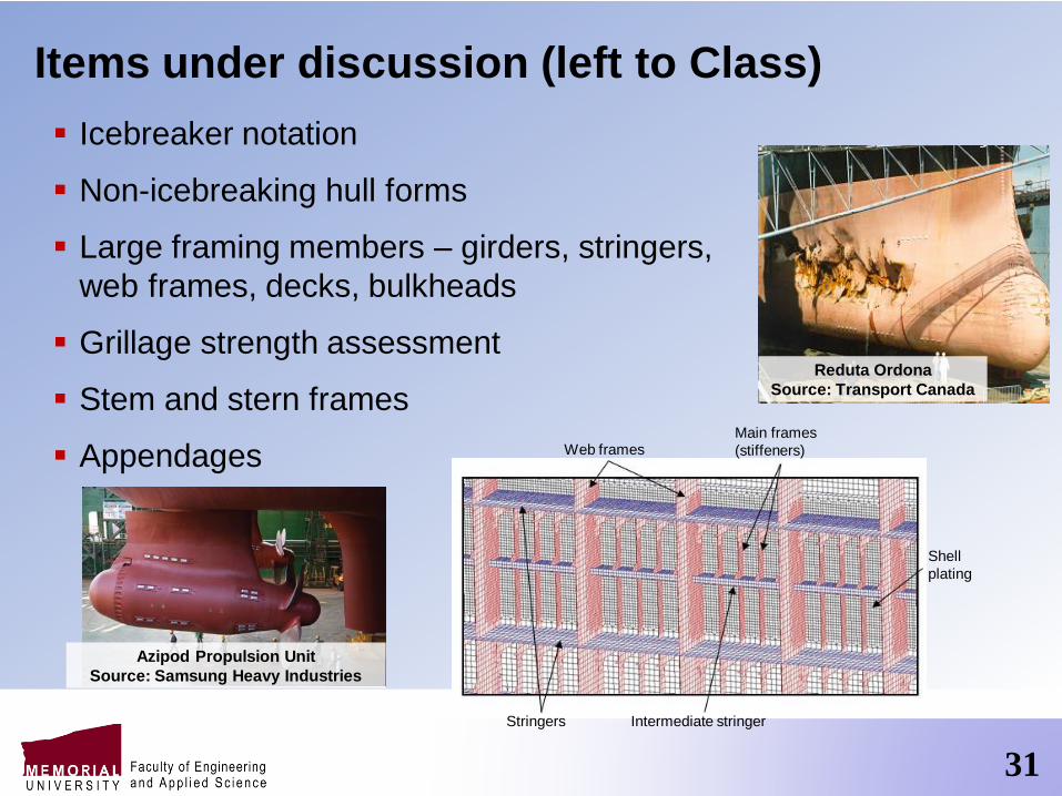
Items under discussion (left to Class)
Icebreaker notation
Non-icebreaking hull forms
Large framing members – girders, stringers,
web frames, decks, bulkheads
Grillage strength assessment
Stem and stern frames
Appendages
Intermediate stringer
Main frames
(stiffeners)
Stringers
Shell
plating
Web frames
Reduta Ordona
Source: Transport Canada
Azipod Propulsion Unit
Source: Samsung Heavy Industries

32
Thank You For Listening
Grounded Icebergs
near St. John’s


