

IMPORTANT NOTE
THESE INSTRUCTIONS MUST BE READ
AND UNDERSTOOD BEFORE INSTALLING,
COMMISSIONING, OPERATING OR
SERVICING EQUIPMENT
PORTLAND PRESSURISATION UNIT FOR LTHW, MTHW AND CHILLED PRESSURISED
WATER SYSTEMS 1.0 TO 2.8 BAR AND 2.8 TO 6.0 BAR COLD
FILL PRESSURES
INSTALLATION, COMMISSIONING AND SERVICING INSTRUCTIONS

Technical Enquiries 01202 662527/662528
To supplement the detailed technical brochures, technical advice on the application and use of products in theHamworthy Heating range is available from our technical team in Poole and our accredited agents.
Site Assembly 01202 662555
Hamworthy offer a service of site assembly for many of our products in instances where plant room area is restricted.Using our trained staff we offer a higher quality of build and assurance of a boiler built and tested by the manufacturer.
Commissioning 01202 662555
Commissioning of equipment by our own engineers, accredited agents or specialist sub – contractors will ensure theequipment is operating safely and efficiently.
Maintenance Agreements 01202 662555
Regular routine servicing of equipment by Hamworthy service engineers inspects the safety and integrity of the plant,reducing the risk of failure and improving performance and efficiency. Maintenance agreements enable our customers toplan and budget more efficiently.
Breakdown service, repair, replacement 01202 662555
Hamworthy provide a rapid response breakdown, repair or replacement service through head office at Poole and accred-ited agents throughout the UK.
Spare Parts 01202 662525
A comprehensive spare parts service is operated from our factory in Poole, providing replacement parts for both currentand discontinued products. Delivery of parts and components is normally from stock within seven days. However, a nextday delivery service is available for breakdowns and emergencies.
Customer Services

HAMWORTHY HEATING LTD Page 500001006/J Portland Pressurisation Unit
PORTLAND PRESSURISATION UNIT FOR LTHW, MTHW AND CHILLED PRESSURISED
WATER SYSTEMS 1.0 TO 2.8 BAR AND 2.8 TO 6.0 BAR COLD
FILL PRESSURES
INSTALLATION, COMMISSIONING AND SERVICING INSTRUCTIONS
NOTE: THESE INSTRUCTIONS SHOULD BE READ AND UNDERSTOOD BEFORE ATTEMPTING TO INSTALL, COMMISSION OR OPERATE THIS UNIT. THE PORTLAND PRESSURISATION UNIT IS INTENDED FOR USE ONLY IN COMMERCIAL/LIGHT INDUSTRIAL APPLICATIONS THIS PRESSURISATION UNIT COMPLIES WITH THE ESSENTIAL REQUIREMENTS OF THE MACHINERY DIRECTIVE 89/392/EEC AMENDED BY 91/368/EEC, THE LOW VOLTAGE DIRECTIVE 73/23/EEC AMENDED BY 93/68/EEC AND THE ELECTROMAGNETIC COMPATIBILITY DIRECTIVE 89/336/EEC AMENDED BY 91/263/EEC AND 92/31/EEC. PUBLICATION NO. 500001006 ISSUE ‘J’ FEBRUARY 2005
i

HAMWORTHY HEATING LTD Page 500001006/J Portland Pressurisation Unit
CONTENTS PAGE 1.0 INTRODUCTION 1 2.0 TECHNICAL DATA 1 2.1 Overall Dimensions 2.2 Technical Data Table 3.0 SEALED SYSTEM OPERATION 1 3.1 Terminology 3.2 Heating Application 3.3 Chiller Application 4.0 OPERATION OF THE PRESSURISATION UNIT 2 4.1 Standard Unit Operation 4.2 Double Pump Option Operation 4.3 Advanced Controls Option Operation 4.4 Twin System Option Operation 5.0 GENERAL REQUIREMENTS 4 5.1 Related Documents 5.2 Mains Water Connections 5.3 Expansion Vessels 5.4 Safety Relief Valves 5.5 Frost Protection 6.0 INSTALLATION 5 6.1 Handling 6.2 Location 6.3 Pipework Connections 6.4 Electrical Connections 7.0 COMMISSIONING 6 7.1 Mechanical Installation 7.2 System Flushing 7.3 Electrical Installation 7.4 System Expansion Vessel 7.5 Accumulator 7.6 Break Tank 7.7 Pump Pressure Switch 7.8 System Pressure Switch 7.9 Pressure Reducing Valve 7.10 Safety and Alarm Circuits 7.11 Setting Information 8.0 FAULT FINDING 9 9.0 SERVICING SCHEDULE 9
ii

HAMWORTHY HEATING LTD Page 500001006/J Portland Pressurisation Unit
10.0 SERVICING AND REPLACEMENT OF COMPONENTS 9 10.1 Pump 10.2 Non-return Valve 10.3 Pressure Reducing Valve 10.4 Accumulator 10.5 Pump Pressure Switch 10.6 System Pressure Switch 10.7 System Expansion Vessel 11.0 HAMWORTHY HEATING RECOMMENDED SPARES 12 12.0 SYSTEM CALCULATIONS 12 FIGURES PAGE 1 Performance and General Data 2 2 Overall Dimensions 13 3 Typical Sealed System Schematic Layout 14 4 Expansion Vessel Operation - Heating Application 15 5 Expansion Vessel Operation - Chiller Application 15 6 Schematic Diagram of Portland Unit Including Options 16 7 Site Wiring Terminals - Single/Double Pump Standard Controls Unit 17 8 Site Wiring Terminals - Single Pump, Advanced Controls Unit 18 9 Site Wiring Terminals - Double Pump, Advanced Controls Unit 19 10 Site Wiring Terminals - Single/Double Pump, Standard Controls, Twin System Unit 20 11 Site Wiring Terminals - Single Pump, Advanced Controls, Twin System Unit 21 12 Site Wiring Terminals - Double Pump, Advanced Controls, Twin System Unit 22 13 Hamworthy Heating Limited Range of Expansion Vessels 23 14 Schematic Layout of System Pipework Connections 24 15 Internal Layout of Typical Portland Units 25 16 Pump Pressure Switch Settings 7 17 General Fault Finding 26/27 18 Heating System Calculation Sheet 28 19 Chiller System Calculation Sheet 29 APPENDIX A - PORTLAND PRESSURISATION UNIT WIRING DIAGRAMS A1 Single Pump, Standard Controls Unit 31 A2 Single Pump, Standard Controls, Twin System Unit 32 A3 Single Pump, Advanced Controls Unit 33 A4 Single Pump, Advanced Controls, Twin System Unit 34/35 A5 Double Pump, Standard Control Unit 36 A6 Double Pump, Standard Controls, Twin System Unit 37/38 A7 Double Pump, Advanced Controls Unit 39/40 A8 Double Pump, Advanced Controls, Twin System Unit 41/42
iii

HAMWORTHY HEATING LTD Page 500001006/J Portland Pressurisation Unit
1
1.0 INTRODUCTION 1.1 The Hamworthy Portland range of pressurisation units are designed to maintain the minimum pressure requirement of modern low/medium temperature, hot water sealed systems, and also the constant pressure requirement of chiller systems. The pressurisation units also provide replacement water for losses from both hot and cold sealed systems. Note! The pressurisation unit is not to be used for the initial filling of the system. 1.2 The pressurisation units incorporate comprehensive safety circuits to shut down the boiler or chiller and the pressurisation unit itself in the event of a fault, ensuring the system operates within health and safety requirements at all times. Also incorporated is the facility for remote fault indication, allowing rapid response and rectification. 1.3 The Portland consists of a robust, plastic coated, sheet steel cabinet with removable door and top access panel. The door incorporates a seal to prevent water ingress and reduce noise emissions from the unit during operation. Housed in the lower cabinet compartment are the pump(s), connecting pipework and flow and pressure controls. In the upper, rear compartment is the header tank, with ball float valve and water level switch. In the upper, front compartment is the unit's control system with drop-down fascia for ease of access. 1.4 Portland range options:- 1) Single or dual pump. Dual pump units include automatic pump changeover on duty pump failure. 2) Standard or advanced controls. Advanced controls include full mimic fascia with pump control switches, audible low water alarm, and system fault volt free contact signalling. 3) Single or twin system. Twin system units include additional system pipework connections, separate safety circuits and alarm signals for both systems and full mimic fascia (advanced controls only). 4) Frost protection. Including frost thermostat, panel heater fitted inside the cabinet and trace heating tape for local external pipework. 1.5 The HPS 2.8 unit and its matching expansion vessel are factory pre-set to suit a set of commonly encountered system conditions. The pre-set conditions are listed in Figure 1. Minimal commissioning checks are required if the site application falls within these values. See section 7.0 COMMISSIONING for details. 2.0 TECHNICAL DATA
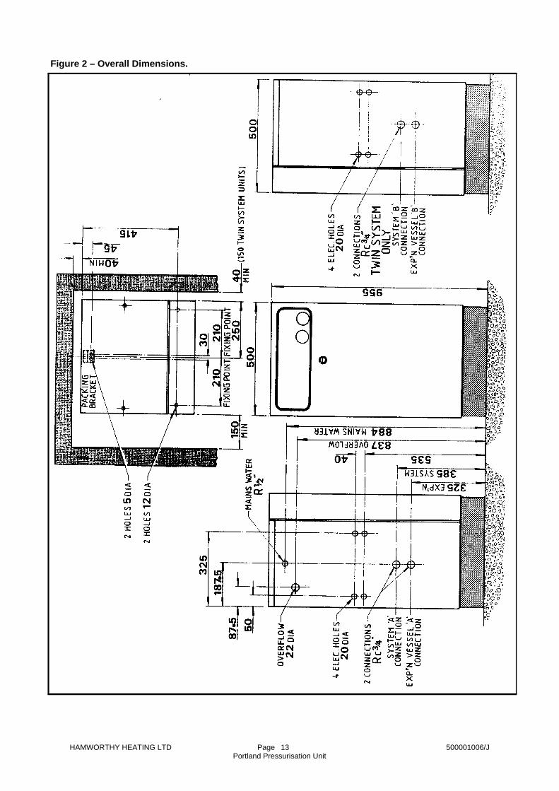
2.1 Overall dimensions are shown in Figure 2. 2.2 Performance and general data is shown in Figure 1. 2.3 Screw threads: All screw threads used in the Portland pressurisation unit conform to the following:- ISO 7/1 or ISO 228/1 for pipe threads where applicable. ISO 262 for all general screw threads. 3.0 SEALED SYSTEM FUNCTION Figure 3 shows the layout of a typical sealed system. 3.1 Terminology 1) Expansion vessel charge pressure - the gas pressure in the expansion vessel with the water connection open to atmosphere. 2) System cold fill pressure - the water pressure in the system that the pressurisation unit is set to maintain. 3.2 Heating application. The system expansion vessel charge pressure is set to the cold fill pressure. Thus, before operation of the boiler, with the system at the cold fill pressure, the expansion vessel is empty of water. (See Figure 4). As the system heats up, due to boiler operation, the expanded volume is absorbed by the expansion vessel. A small pressure rise occurs (Boyle’s Law) which the expansion vessel is designed to accommodate. When the system cools the pressure drops, and if there has been some fluid loss the pressurisation unit replaces the lost water to maintain the system cold fill pressure. 3.3 Chiller application. The system expansion vessel charge pressure is set to 0.35bar (5.0psi) below the cold fill pressure. Thus before operation of the chiller, with the system at the cold fill pressure, the expansion vessel is partially filled with water. (See Figure 5). As the chiller operates, the water cools and contracts, pulling water from the system expansion vessel and causing a drop in system pressure. The pressurisation unit operates to maintain the system cold fill pressure. When the system warms to ambient temperature, the water expands and is absorbed by the expansion vessel. The system pressure rises.

HAMWORTHY HEATING LTD Page 500001006/J Portland Pressurisation Unit
2
Figure 1 - Performance and General Data.
Minimum cold fill pressure bar
1.0
2.8
Maximum cold fill pressure bar
2.8
6.0
Maximum operating pressure bar
8.0
8.0
Maximum water flow rate @ maximum cold fill pressure l/min
12
8 Weight kg
Single pump unit - 70 Double pump unit - 80
Noise emissions dBA (At unit centreline, 1 m from front)
< 70
ELECTRICAL DATA
Electrical supply Power rating W
600
1400
Safety circuit and volt free contact rating
240V ~ 50 Hz
3A resistive, 0.8A inductive FACTORY PRESET VALUES
Pressure reducing valve bar
1.8
4.0
System low pressure switch bar
1.5
3.7
System high pressure switch bar
3.65
5.35
Expansion vessel charge pressure bar
1.7
To suit system conditions *
Maximum water flow temp EC
82
-
Maximum static height m
16.5
-
Minimum system maximum operating pressure bar
3.3
-
230V ~ 50 Hz
4.0 OPERATION OF THE PRESSURISATION UNIT Figure 6 shows the schematic layout of the Port-land and optional components. 4.1 Standard unit operation. 4.1.1 A drop in system pressure due to, for ex-ample, loss of water, will cause water stored in the unit's accumulator to flow through the unit's pressure reducing valve, into the system, to maintain the cold fill pressure. If the water loss is greater than the volume of the accumulator, the pump pressure switch will oper-
ate the pump to recharge the accumulator to 2.8bar or 6.0bar (depending on model). When the pump pressure switch is satisfied the pump stops. A ~230V ‘normal pressure’ signal can be derived at terminal ‘22’ (see Figure 7). 4.1.2 Safety functions:- 1) High system pressure due to, for example, failure of the system expansion vessel or the unit's pressure reducing valve, will cause the boiler/chiller safety circuit to be interrupted, shut-ting down the boiler/chiller. A ‘high-pressure’ alarm signal, derived from the safety circuit, can be obtained at terminal ‘8’ (see Figure 7).
* Note! If site application falls outside these values or a HPS 6.0 unit is being installed the pressuri-sation unit will require full commissioning. See section 7.0 COMMISSIONING for details.

HAMWORTHY HEATING LTD Page 500001006/J Portland Pressurisation Unit
3
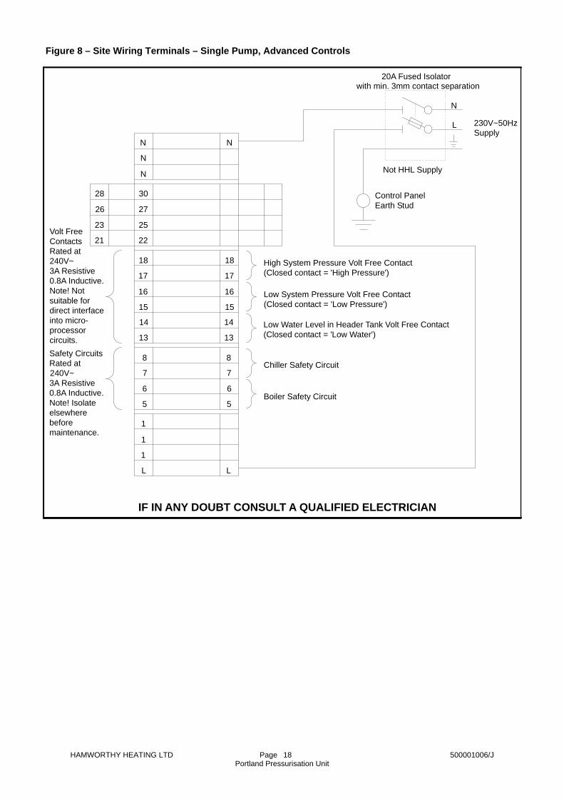
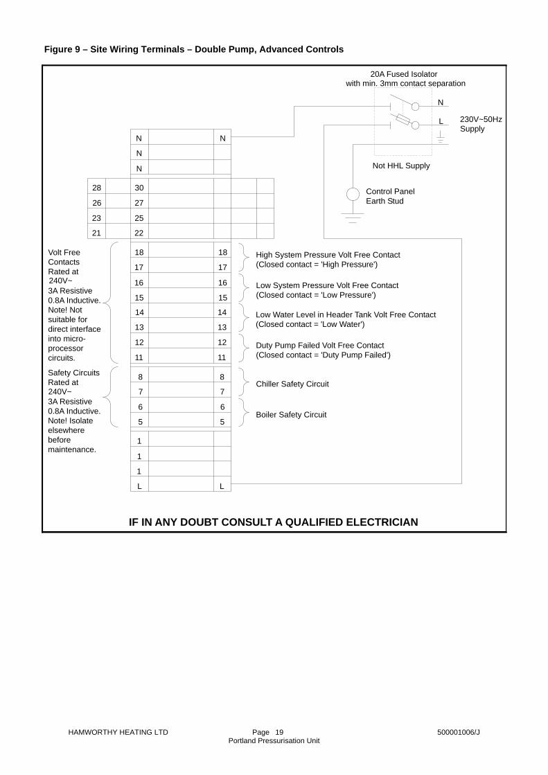
2) Low system pressure due to, for example, pump failure, a system water loss in excess of the maximum flow rate of the pump (see Figure 1) or a low water condition (see below), will cause the boiler/chiller safety circuit to be interrupted, shutting down the boiler/chiller. A ‘low-pressure’ alarm signal, derived from the safety circuit can be obtained at terminal ‘7’ (see Figure 7) 3) Low water level in the unit's header tank due to, for example, failure of the mains water supply or a system leak rate greater than the header tank make up water flow rate, will cause the unit's pump to be shut down. This condition could lead to a low system pressure condition if there is a system water leak. Note! The cause of the abnormal condition should be investigated. All of the safety functions automatically reset when the abnormal condition is removed. 4.2 Double pump option operation. These pressurisation units have the additional function of automatic changeover to the standby pump on failure of the duty pump. If the pump pressure switch is not satisfied within 10 seconds of the duty pump starting then operation, switches to the standby pump and the ‘duty pump failed’ neon on the unit's fascia illuminates. Manual operation of the ‘pump reset’ switch on the unit's fascia will switch operation back to the duty pump. Note! The cause of the pump failure must be investigated before resetting to duty pump. 4.3 Advanced controls option operation. 4.3.1 Additional functions:- 1) Hand/Off/Auto switch - In ‘auto’ mode the pressurisation unit operates as described in section 4.1.1. In ‘hand’ mode the pump pressure switch is overridden, thus the pump will run continuously whilst the switch is in the ‘hand’ position. However, a ‘high system pressure’ or ‘low water’ condition will disable the pump in both auto and hand modes. 2) Boiler and chiller safety circuits - Separate boiler and chiller safety circuits are provided. The boiler safety circuit will shut down the boiler in the event of high system pressure, low system pressure and low water. The safety circuit will shut down the chiller in the event of low system pressure only. The safety circuits are rated at 230V~3A resistive load or 0.8A inductive load. See Figure 8 and Figure 9 for wiring details. 3) Volt free contacts - These are provided for high system pressure, low system pressure, low water and duty pump failed (double pump units only) signals. The volt free contacts are rated at 230V~3A resistive
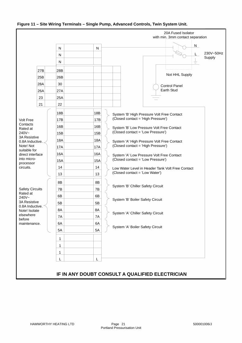
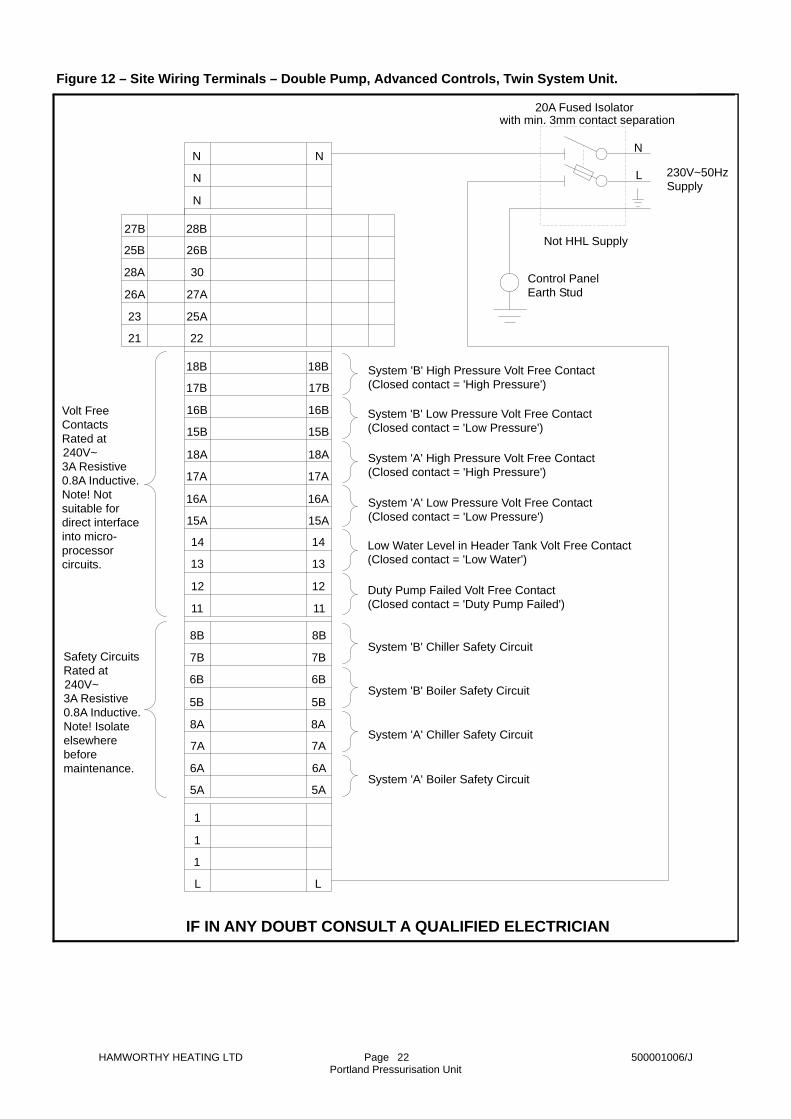
load, or 0.8A inductive load. See Figure 8 and Figure 9 for wiring details. 4) Full mimic fascia - Includes neon indicators for all pressurisation unit and system conditions. 5) Low water buzzer - In the event of a header tank low water condition an alarm buzzer will sound. The buzzer can be silenced by manual actuation of the alarm mute button on the unit's fascia. 6) Pump selector switch (double pump units only) - This switch enables either pump to be set as the duty pump to allow equal run time on each pump. Pump changeover occurs as described in section 4.2. 7) Hours run meter - Displays the pump hours run. A double pump unit has an hours run meter for each pump. 4.3.2 Safety functions:- 1) A high system pressure condition will operate the ‘high system pressure’ volt free contact, interrupt the boiler safety circuit and disable operation of the pump. The ‘high system pressure’ neon indicator on the fascia will illuminate. 2) A low system pressure condition will operate the ‘low system pressure’ volt free contact and disable both the boiler and chiller safety circuits. The ‘low system pressure’ neon indicator on the fascia will illuminate. 3) A header tank low water condition will operate the ‘low water’ volt free contact, interrupt the boiler safety circuit and disable operation of the pump. The ‘low water’ neon indicator on the fascia will illuminate and the alarm buzzer will sound. 4) A duty pump failed condition (double pump units only) will additionally operate the ‘duty pump failed’ volt free contact. 4.4 Twin system option operation. 4.4.1 Twin system pressurisation units have system connections on both sides of the cabinet. The left hand connections are designated system ‘A’ and the right hand, system ‘B’. If the pressurisation unit is for use on one heating system and one chiller system, the heating system must be connected to the ‘A’ connections. The pressurisation unit functions to maintain the same cold fill pressure in both systems. The system working pressure of the individual systems is determined by the size and charge pressure of the system expansion vessels. If in doubt refer to Hamworthy Heating Ltd for sizing information.

HAMWORTHY HEATING LTD Page 500001006/J Portland Pressurisation Unit
4
The two non-return valves (see Figure 6) act to prevent backflow from one system at high pressure to the other at a lower pressure. 4.4.2 The controls are identical to those of the single system units, but with the addition of extra controls to monitor the second system. Standard controls units have an additional boiler/chiller safety circuit to monitor system ‘B’. High and low system pressure signals derived from the system ‘B’ safety circuit can also be obtained. See Figure 10 for wiring details. Advanced controls units have additional separate boiler and chiller safety circuits, and high and low system pressure volt free contacts to monitor system ‘B’. See Figure 11 and Figure 12 for wiring details. These additional controls operate identically to those of the single system units as previously described. 5.0 GENERAL REQUIREMENTS 5.1 Related documents. Pressure Systems and Transportable Gas Containers Regulations 1989. It is law that pressure system appliances are installed by competent persons in accordance with the above regulations. Failure to install appliances correctly could lead to prosecution. It is in your own interest and that of safety, to ensure that this law is complied with. The installation of the pressurisation unit and expansion vessel MUST be in accordance with the relevant requirements of the Pressure System Regulations, Building Regulations, IEE Regulations and the bylaws of the local water undertaking. It should also be in accordance with any requirements of the local authority and the relevant recommendations of the following documents:- BS6644: Installation of Gas Fired Hot Water Boilers - 60kW to 2MW. BS799: Specification for Oil Burning Equipment. BS6880 Part 1, 2 and 3: Code of practice for low temperature hot water heating systems of output greater than 45kW. BS7074: Application, selection and installation of expansion vessels and ancillary equipment for sealed water system. Part 2: Code of Practice for low and medium
temperature hot water heating systems. Part 3: Code of Practice for chilled and condenser systems. BS6759 Part 1 (ISO 4126): Specification for safety valves for steam and hot water. BS3456 (CEE10 Part 1, CEE11 Part 1): Safety of household and similar electrical appliances. HSE Guidance note PM5 - Automatically controlled steam and hot water boilers. 5.2 Mains water connections. All connections to the local water main must comply with WRC Regulations including any local requirements. The system temporary fill connection must be as per water supply bylaws, and must be removed after initial filling. Note! The pressurisation unit must not be used to initially fill the system. 5.3 Expansion Vessels. System expansion vessels must be constructed to BS4814 or BS6144. The required expansion vessel size is detailed in the Portland Unit contract documents. If these are not available refer to section 12.0 SYSTEM CALCULATIONS, otherwise if in any doubt contact Hamworthy Heating Limited for comprehensive system sizing information. Hamworthy Heating Ltd can supply a range of expansion vessels with volumes ranging from 8 to 2000 litres, rated at 100°C and 8 or 10 bar maximum working pressure. Figure 13 lists the range of vessels available. Hamworthy Heating Limited expansion vessels are supplied with a charge pressure of 1.7 bar to minimise commissioning on applications falling within the parameters detailed in Figure 1. Expansion vessels are commonly fitted with EPDM or butyl rubber diaphragms. These materials are suitable for use with pure water and antifreeze contents of up to 15%. For higher antifreeze contents (up to 40%) a nitrile rubber diaphragm must be specified. Consult Hamworthy Heating Limited for details. 5.4 Safety relief valve. The system safety relief valve must comply with BS6759 part 1, and be sized and installed in accordance with BS6644 and BS7074.

HAMWORTHY HEATING LTD Page 500001006/J Portland Pressurisation Unit
5
5.5 Frost protection. If conditions within the boiler house are likely to fall below freezing, an optional kit can be fitted to the pressurisation unit, to heat the inside of the unit and also local, external pipework to prevent freezing. Consult Hamworthy Heating Limited for details. 6.0 INSTALLATION 6.1 Handling. The pressurisation unit is supplied bolted onto a wooden pallet, inside a robust cardboard carton. The unit should be transported to its point of installation, by fork lift or sack truck, whilst still in its packaging. Then the carton can be removed and the unit unbolted from its pallet. To unbolt from the pallet remove the unit's door by turning the ¼ turn latch. The packing bolts can be accessed through the 2 holes in the units base plinth. Slide the unit backwards to disengage the rear packing bracket, and walk the unit carefully off the pallet and into position. Note! Retain the packing bracket if the unit is to be bolted in position. 6.2 Location. The recommended minimum clearances around the pressurisation unit are detailed in Figure 2. The pressurisation unit is designed for base mounting only. If it is required to mount the unit on a wall, a suitable mounting cradle must be firmly attached to the wall, taking into account the canti-lever forces. (See Figure 1 for unit weights). If the unit is to be fixed in position, the 2 fixing holes in the base plinth and the packing bracket (see section 6.1) are utilised. Refer to Figure 2 for fixing hole positions. The packing bracket is first fixed to the floor and the unit lifted over it and then slid forwards to engage the bracket in the unit's plinth. Note! The minimum rear clearance must be allowed for. The front 2 fixings can then be applied. If a finished floor screed is to be applied when all mechanical services are complete, it is advisable to mount the pressurisation unit and expansion vessel(s) on a concrete plinth. 6.3 Pipework Connections. Figure 14 shows a schematic layout of the Portland unit pipework connections. 1) Mains water connection.
The Portland unit is fitted with a type ‘A’ air gap device to BS6281 part 1 : 1992. The unit can therefore be connected directly to the water main without the need for an intermediate break tank. To obtain access to the header tank remove the 2 black snap in plugs in the top access panel. Undo the 2 captive screws exposed and lift off the panel. The 15mm water supply connection must conform to all local WRC regulations. The ball float valve is suitable for direct connection with a 15mm copper compression fitting. The mains connection position is shown in Figure 2. Note! Ensure correct ball float valve orientation when the pipework is installed. The Portland unit is fitted with a high pressure BS1212 part 2 ball float valve. When connected to a low-pressure water supply a slow fill rate may be observed, which could lead to nuisance low water shutdowns. In this situation Hamworthy Heating recommend the replacement of the ball valve assembly with a low-pressure version. 2) Overflow connection. The Portland unit header tank is fitted with a 22mm plastic, female connection. This should be piped away to a position where it will cause a nuisance and ensure an overflow condition can be noticed and corrected. If in doubt consult water bylaws. 3) System connection. The Portland unit must be connected to the system by an antigravity loop (see Figure 14). The units system connection is Rc¾ BSP, and its position is shown in Figure 2. The antigravity loop (see Figure 14) must be made in pipework no smaller than the expansion vessel connection, and have a minimum height of 2 metres. It should include a lockshield (or lockable) valve at the system connection point for servicing. An automatic air vent must be fitted at the highest point of the loop. The antigravity loop must not be lagged, but can be fitted with trace heating tape to prevent freezing (see section 5.5 Frost protection). If the system return water temperature is likely to exceed 100°C, an intermediate storage vessel must be installed in the downward leg of the antigravity loop (see Figure 14). The storage vessel volume should be 8% of the installed expansion vessel volume. Consult Hamworthy Heating Limited for details. Twin system models - the left hand connections are
HAMWORTHY HEATING LTD Page 500001006/J Portland Pressurisation Unit
6
for system ‘A’ and the right hand for system ‘B’. If a combination of heating and chiller systems are to be connected, the heating system must be system ‘A’. The pipework and fittings must be pressure tested to 1½ times the safety valve lift pressure. 4) Expansion vessel connection. The Portland unit has a Rc¾ BSP connection for the expansion vessel. See Figure 2 for the connection position. The pipework used must be no smaller than the expansion vessel connection. If copper tube is used, sufficient protection should be provided to prevent damage to the pipework. The pipework must include a lockshield (or lockable) valve and a drain valve (see Figure 14) to allow the expansion vessel to be drained for servicing. The pipework and fittings must be pressure tested to 1½ times the safety valve lift pressure. 6.4 Electrical connection. All wiring to the Portland unit must be in accordance with the IEE regulations, and any local regulations which apply. Note! If in any doubt a qualified electrician should be consulted. The site wiring terminals are shown in Figures as follows:- Figure 7 - Single/double pump, standard controls units. Figure 8 - Single pump, advanced controls units. Figure 9 - Double pump, advanced controls units. Figure 10 - Single/double pump, standard controls, twin system units. Figure 11 - Single pump, advanced controls, twin system units. Figure 12 - Double pump, advanced controls, twin system units. Note! Full Portland unit schematic wiring diagrams are included in appendix A, for further reference. 4 off 20mm diameter knockouts are provided on each side of the Portland unit for electrical cable entry. 1) Mains supply. The electrical mains connection must be via a double pole, fused isolator with a contact separation of at least 3mm in both poles. The isolator must be rated at 20A and be positioned local to the Portland unit.
Note! The electrical supply must not be interrupted by any time clock controls, etc. 2) Boiler/chiller safety circuits. These volt free circuits will interrupt a boiler/chiller control signal, in order to shut down the boiler or chiller system in the event of a system fault condition. The boiler/chiller control system must be designed such that manual resetting is required after a system fault condition. The circuits are rated at 230V~50Hz, 3A resistive load or 0.8A inductive load. Twin system units have individual safety circuits for each system. Provision must be made to enable the safety circuit to be electrically isolated. 3) Alarm signals. Standard controls units:- The normal pressure signal is a 230V~50Hz signal. The ‘high’ and ‘low’ system pressure signals are derived from the boiler/chiller safety circuit. Thus they will be in the form of the boiler/chiller control signal, e.g. 230V~, 5V, etc. Advanced controls units:- The alarm signal volt free contacts are rated at 240V~50Hz, 3A resistive load or 0.8A inductive load. Provision must be made to enable the volt free contacts to be electrically isolated. 7.0 COMMISSIONING All HPS 2.8 units are supplied factory set and tested to suit the system parameters shown in Figure 1. If the site application falls within these parameters the HPS 2.8 unit will require minimal commissioning checks. The required commissioning checks are those items in the sequence of operations marked with an asterisk. All other systems will require full commissioning. The system settings are detailed in the contract documents. If in any doubt consult Hamworthy Heating Limited. Note! It is recommended that commissioning is carried out in the sequence shown.
HAMWORTHY HEATING LTD Page 500001006/J Portland Pressurisation Unit
7
Refer to Figure 15 for the internal layout of the Portland unit. 7.1* Mechanical installation. Check that the Portland unit and expansion vessel(s) have been installed correctly, as detailed in section 6.3: Pipework connections. Check also that all lockshield or lockable valves are closed. 7.2* System flushing. Ensure that the system has been flushed and all foreign matter has been removed, including pipe scale. Note! Should this material come into contact with the expansion vessel diaphragm it could result in premature failure of the expansion vessel assembly. 7.3* Electrical Installation. Note! Before working on the Portland unit ensure that all electrical circuits connected to it are isolated. Remove the unit's door by turning the ¼ turn latch. Drop the hinged fascia and check that the electrical connections are correct (refer to section 6.4: Electrical connection). Check, and set if necessary, the pump contactor overload(s) settings. The setting must match the Full Load Current rating on the pump's data plate. Remove the 2A control fuse (on the fascia) and the pump fuse(s) (on the terminal rail next to the pump contractors). 7.4* System expansion vessel. To set or check the expansion vessel charge pressure, the lockshield valve between the Portland unit and the vessel must be closed. The drain cock fitted on the base of the expansion vessel must be open to allow any water in the vessel to escape. A suitable gauge should be used to check the charge pressure. Generally a Schrader ‘car type’ valve is fitted near the top of the expansion vessel. If the charge pressure is too high, it can be reduced by depressing the centre of the Schrader valve or by using a pressure gauge with an integral air release valve. If the charge pressure is too low, an oil free compressor or nitrogen bottle supply can be utilised. A car foot pump can be used if the pressure change is small, otherwise it is not recommended. Note! In a heating system the charge pressure and the cold fill pressure are the same. However, to allow for pressure gauge inaccuracy it is
recommended that the charge pressure be set to 0.1bar less than the cold fill pressure. When the correct pressure is set, the Schrader valve protective cap must be replaced. Check the integrity of the pipework. Ensure the lockshield valve between the Portland unit and the expansion vessel is open and the drain valve is closed. Ensure the air purge plug is fitted (near the top of the expansion vessel). Note! Twin system applications - carry out these operations on both system expansion vessels. 7.5* Accumulator. The Portland unit's internal accumulator is factory set and must not be adjusted. However, the accumulator charge pressure can be checked as detailed in section 7.4. Note! The pressurisation unit must be drained and open to atmosphere to take the charge pressure reading. Settings:- HPS 2.8 - 1.5bar
HPS 6.0 - 4.0bar Ensure the dust cap and shield are replaced after the check is made. 7.6* Break tank. Remove the top access panel by removing the 2 black snap in plugs and unfastening the captive screws exposed. Open the mains water inlet valve and check that the ball float valve operates correctly. Ensure that the pump isolating valve(s) is open (handle/slot on valve in line with flow). Check that the pump(s) are primed by loosening the priming plug on the pump casing. Ensure that the system has been filled and open the system isolating valve. 7.7* Pump pressure switch. Ensure that the electrical mains supply is isolated. Insert the control and pump fuses. If the unit has the advanced control option, set the ‘hand/off/auto’ switch to the ‘auto’ position. Switch on the power supply; the unit will operate. Check the operation of the pump pressure switch by observing the pump pressure gauge (on twin system units the pump pressure gauge is mounted in a

HAMWORTHY HEATING LTD Page 500001006/J Portland Pressurisation Unit
8
bracket beneath the controls) as the pump cuts in and out. The cut in and cut out pressures should approximate the settings listed in Figure 16. Figure 16 - Pump pressure switch settings
Check operation of the ‘low water’ switch by depressing the black float mounted in the header tank. The pump will stop running and on advanced controls units the ‘low water’ indicator will illuminate and the ‘low water’ alarm will sound. Press the ‘alarm mute’ button to silence the alarm. On releasing the float switch the ‘low water’ indicator will be extinguished and the pump will run. If a double pump unit is fitted it is likely that during this initial charging cycle, the pump changeover circuit will operate. When the pump's cycling frequency has reduced, press the ‘pump reset’ button (on the fascia) to reset the duty pump. 7.8 System pressure switch. Ensure the boiler/chiller safety circuit(s) are isolated. Note! Units with advanced controls option - the system pressure switch contacts are LIVE! Take care to avoid the contacts whilst adjusting the switch. Remove the green cover from the system pressure switch, by unfastening the screw at the top, to gain access to the setting adjusting screws. The left hand indicator on the front of the switch shows the low pressure setting, the right hand indicator shows the high pressure setting. Isolate the unit from the system by closing the system isolating valve. Turn the adjusting screw on the pressure reducing valve fully anti-clockwise. Open the drain cock in the expansion vessel line to initiate a small leak. Note! The unit should be allowed to cycle whilst setting the system pressure switch. 7.8.1 Low pressure setting. Connect a continuity tester across terminals 5 and 7 on the units terminal rail. Note! The unit is live. Take care to avoid contact with the grey terminals.
With the system pressure gauge reading zero there should be continuity between terminals 5 and 7. Increase the pressure to the low pressure setting (cold fill pressure minus 0.3bar) on the system pressure gauge, by turning the adjusting screw on the pressure reducing valve clockwise. Adjust the front adjusting screw on the pressure switch, with a 4 BA open-ended spanner or similar, until continuity across terminals 5 and 7 is lost. Note! Do not force the adjusting screw. The pressure switch will not allow the low-pressure setting to be higher than the high-pressure setting. If necessary adjust the rear adjusting screw to increase the high-pressure setting. 7.8.2 High pressure setting. Connect the continuity tester across terminals 5 and 8. There should be no continuity at the cold fill pressure. Increase the pressure to the high pressure setting (hot working pressure plus 0.35bar) on the system pressure gauge by turning the adjusting screw on the pressure reducing valve clockwise. If the unit cannot attain the required pressure, reduce the leak through the drain valve. If the pressure is still too low, connect the unit to the water main via the WRC approved quick fill connection to achieve the required pressure. Alternatively a ‘Rigid’ type hydraulic tester can be used. Adjust the rear adjusting screw on the pressure switch, until continuity is made across terminals 5 and 8. Replace the system pressure switch cover. Reconnect the boiler/chiller safety circuit to the unit. 7.8.3 Advanced controls option. A continuity tester is not required. At zero pressure the ‘low-pressure’ indicator on the fascia will be illuminated. When the required low-pressure setting on the switch is achieved the ‘low-pressure’ indicator will be extinguished. When the required high-pressure setting on the switch is achieved the ‘high-pressure’ indicator on the fascia will illuminate. 7.8.4 Twin system option.
Model Cut in pres-sure
Cut out pres-sure
HPS 2.8
2.8bar
3.1bar
HPS 6.0
5.8bar
6.2bar

HAMWORTHY HEATING LTD Page 500001006/J Portland Pressurisation Unit
9
The sequence of operations is repeated for both system pressure switches. The left hand switch is for the left hand system (system A), the right hand switch is for the right hand system (system B). Terminals 5A, 7A and 8A are used for the continuity tests on system A, terminals 5B, 7B and 8B are used for the continuity tests on system B. 7.9 Pressure reducing valve. Ensure the drain cock in the expansion vessel line is slightly open to initiate a small leak. Adjust the adjusting screw on the pressure reducing valve until the required cold fill pressure is observed on the system pressure gauge on the unit's fascia. Ensure the drain cock is closed and open the system isolating valve. 7.10* Safety and alarm circuits. Once the above procedure is correctly completed the boilers/chillers can be switched on. Ensure that the boiler/chiller safety circuit(s) shut down the boilers or chillers and that the alarm systems operate as required. 7.11* Setting information. When the unit has been commissioned the relevant setting information should be entered on the schematic diagram on the inside of the Portland unit's door for future reference. Replace the top access panel and the door. 8.0 FAULT FINDING General fault finding is shown in Figure 17. If the Portland unit still does not operate satisfactorily, consult your local office of Hamworthy Heating for assistance. 9.0 SERVICING SCHEDULE By law the whole pressurised system must be serviced by a competent person in accordance with the Pressurised Systems and Transportable Gas Containers Regulations 1989. The following is a recommended servicing schedule for the Portland unit and expansion vessel. If remedial action is required, refer to section 10: SERVICING AND REPLACEMENT OF COMPONENTS. If in doubt consult Hamworthy Heating.
9.1 At 6 monthly intervals:- 1) Check the expansion vessel charge pressure, as described in section 7.4. A significant drop in charge pressure could be due to a faulty vessel diaphragm; replacement of diaphragm should be considered. See section 10.8. 2) Check the accumulator charge pressure, as described in section 7.5. A significant drop in charge pressure could be due to a failure of the vessel; replacement of the entire accumulator should be considered. See section 10.4. 3) Briefly run the pump(s) to check for rotor seizure. This could occur if the pumps do not run for extended periods. This can be accomplished by slightly opening the expansion vessel drain valve to initiate a leak. To run the standby pump on double pump units, close the union ball valve on the duty pump outlet. The pump changeover circuit will operate and the standby pump will run. Open the duty pump union ball valve and press the pump reset button on the fascia to reset to the duty pump. Note! Ensure that the drain valve is closed after this operation. On advanced controls units the pump(s) can simply be run by setting the ‘hand/off/auto’ switch to ‘hand’. To run the standby pump (on double pump units) change over the ‘pump select’ switch. Note! Ensure that the ‘hand/off/auto’ switch is returned to ‘auto’ after this operation. 9.2 At 12 monthly intervals additionally:- 1) Remove the top access panel and unscrew and clean the pump strainer(s). Ensure the strainers are refitted. Note! Ensure that tank residue does not enter the pump inlet during this operation. 2) Check the ball float valve diaphragm seat for integrity and replace if necessary. Also check the plastic float for soundness. 3) Check the expansion vessel and accumulator for signs of external corrosion. If any deterioration is observed then it is recommended that the frequency of inspection be increased. 4) Check the operation of the boiler/chiller safety circuit(s) and also the alarm circuits if utilised. 9.3 A 4 yearly intervals additionally:- 1) Remove the expansion vessel diaphragm as described in section 10.8 and inspect for wear/ageing. Inspect the internal surface of the vessel for corrosion.
HAMWORTHY HEATING LTD Page 500001006/J Portland Pressurisation Unit
10
Significant corrosion can lead to failure of the vessel; replacement of the entire vessel should be considered. If necessary replace the diaphragm as described in section 10.8. 10.0 SERVICING AND REPLACEMENT OF COMPONENTS Note! When servicing or replacing Portland unit pressure system components, electrically isolate the unit and close the system and expansion vessel isolating valves. Isolate the mains water supply to the unit's header tank. Drain the Portland unit utilising the internal drain valve(s). When remaking screwed connections use a thread sealant (see Section 11: RECOMMENDED SPARES). 10.1 Pump. 10.1.1 To free a seized pump impeller, first electrically isolate the unit and remove the door. Remove the pump's fan cover to expose the cooling fan, and work it backwards and forwards gently to clear the impeller. If this is not possible the pump will have to be removed and stripped for inspection. 10.1.2 To remove a pump, first follow the procedure detailed in section 10.0. Disconnect the electrical cable from the pump, taking note of the conductor positions. Close the union ball valve on the pump outlet and unscrew the union. Allow the disconnected pipework to hang to one side. Disconnect the pump inlet flexible hose from the header tank. Unbolt the pump from the base plinth and remove. Unscrew the pipe fittings from the pump inlet and outlet connections. Refitting of the pump is a reverse of the above procedure. To restart the Portland unit follow steps 7.1, 7.3, 7.6 and 7.7 of the commissioning procedure in section 7.0. 10.2 Non-return valve. To remove a non-return valve, first follow the procedure detailed in section 10.0. Close the union ball valve on the non-return valve outlet and unscrew the union. Allow the disconnected pipework to hang to one side. Unscrew the union from the non-return valve and then unscrew the non-return valve. Clean the valve seat, or if the seat shows signs of wear or damage replace the non-return valve. Refitting of the non-return valve is a reverse of the above procedure. To restart the Portland unit follow
steps 7.1, 7.6 and 7.7 of the commissioning procedure in section 7.0. 10.3 Pressure reducing valve. 10.3.1 To service the pressure reducing valve, first follow the procedure detailed in section 10.0. Unscrew the plastic part of the pressure reducing valve and remove with the spring. Carefully pull out the internal cartridge with a pair of pliers applied to the central bolt head. Clean the valve strainer and seat. If the seat shows signs of wear/damage the pressure reducing valve will require replacement. Re-assembly is a reverse of the above procedure. Ensure that the strainer is refitted. To restart the Portland unit follow steps 7.1, 7.6, 7.7 and 7.9 of the commissioning procedure in section 7.0. 10.3.2 To remove the pressure reducing valve, first follow the procedure detailed in section 10.0. Disconnect the flexible hose(s) from the pressure reducing valve outlet and then unscrew the remaining pipework from the valve's outlet. Unscrew and remove the accumulator using a suitable strap wrench. Unscrew the elbow, on the pressure reducing valve inlet, from the pump manifold through a quarter turn. Unscrew the pressure reducing valve. Fully unscrew the elbow from the pump manifold before reassembly. Re-assembly is a reverse of the above procedure. To restart the Portland unit, follow steps 7.1, 7.6, 7.7 and 7.9 of the commissioning procedure in section 7.0. 10.4 Accumulator To remove the accumulator, first follow the procedure detailed in section 10.0. Unscrew the accumulator using a suitable strap wrench. Re-assembly is a reverse of the above procedure. To restart the Portland unit follow steps 7.1, 7.5 and 7.6 of the commissioning procedure in section 7.0. 10.5 Pump pressure switch. To remove the pump pressure switch, first follow the procedure detailed in section 10.0. 10.5.1 HPS 2.8 units. Disconnect the pump pressure switch electrical cable from the control panel (see Appendix A for full wiring diagram details).

HAMWORTHY HEATING LTD Page 500001006/J Portland Pressurisation Unit
11
Unscrew the pump pressure switch from the pump manifold. Re-assembly is a reverse of the above procedure. To restart the Portland unit follow steps 7.1, 7.6 and 7.7 of the commissioning procedure in section 7.0. 10.5.2 HPS 6.0 units. Remove the plastic cover from the pump pressure switch and disconnect the electrical cable. Unscrew the tubing connection from the switch's pressure connection. Unscrew the switch bracket from the cabinet and remove. Unscrew the tubing connection adapter fitting from the switch. Attach the replacement switch to its bracket with the 2 screws provided. Screw the tubing connection adapter to the switch. Fit the bracket to the cabinet and attach the tubing connection. Remove the plastic cover from the switch and connect the electrical cable (see Appendix A for full wiring diagram details). Replace the cover. Set the pressure setting on the switch's indicator to 6.0bar with the ‘P’ adjusting screw. Set the ‘DP’ adjusting screw to the 9 o'clock position. To restart the Portland unit follow steps 7.1, 7.6 and 7.7 of the commissioning procedure in section 7.0. If necessary adjust the set point ‘P’ and the differential ‘DP’ to obtain the correct pump cut in and cut out pressures. 10.6 System pressure switch. To remove the system pressure switch, first follow the procedure detailed in section 10.0. Remove the pressure switch cover and disconnect the electrical cable. Note! Ensure all electrical supplies to the unit are isolated. Unscrew the tubing connection from the switch's pressure connection. Unscrew the switch from the cabinet and remove. Unscrew the tubing connection adapter fitting from the switch. Re-assembly is a reverse of the above procedure. Refer to Appendix A for electrical connection details. To restart the Portland unit follow steps 7.1, 7.6 and 7.8 of the commissioning procedure in section 7.0. 10.7 Control system. Before carrying out any work on the control system, always isolate all electrical supplies to the Portland unit. Note! If in any doubt consult a qualified electrician.
Full Portland unit electrical wiring diagrams are included in Appendix A. 10.7.1 Replacing fuses. The control fuse is located on the Portland unit fascia. A 2A, 20mm x 5 dia fuse is required (see Section 11: RECOMMENDED SPARES). The pump fuse(s) are located inside the control housing, on the terminal rail. A 10A, 20mm x 5 dia motor rated fuse is required (see Section 11: RECOMMENDED SPARES). Note! Investigate the cause before replacing any fuses. 10.7.2 Pump overload relay. The pump overload relay(s) are located inside the controls housing on the terminal rail. To reset a tripped overload press the red button on the relay. Note! The cause of the tripped overload must be investigated before resetting. 10.8 System expansion vessel. To replace the system expansion vessel diaphragm - Turn off the boiler/chiller and electrically isolate the Portland unit. Close the system isolating valve and isolate the mains water supply to the unit's header tank. Drain the Portland unit and the expansion vessel. Note! Leave the drain cock open. Disconnect the expansion vessel pipework. Unscrew the diaphragm top connection (normally a brass nut at the opposite end to the water entry). Remove the bolts from the flange at the base of the vessel and remove the diaphragm. To replace the diaphragm drop a R½ BSP plug fixed to a line of string or wire down through the top connection hole. Screw the plug lightly into the diaphragm top connection and pull it up through the expansion vessel. Lockup the diaphragm top connection and tighten the water connection flange screws. Note! Ensure that the diaphragm is not twisted. Reconnect the expansion vessel pipework. To restart the system follow steps 7.1, 7.4 and 7.6 of the commissioning procedure in section 7.0.

HAMWORTHY HEATING LTD Page 500001006/J Portland Pressurisation Unit
12
12.0 SYSTEM CALCULATIONS 12.1 Calculation sheets for both heating and chiller systems can be found in Figure 18, and Figure 19. These figures also include example calculation. 12.2 Calculation notes. 12.2.1 System volume - If the system volume is not known then the following rule of thumb can be applied: Heating systems - 10 litres/kW of installed boiler power. e.g. Boiler = 200 kW System volume = 200 x 10 = 2000 litres. Chiller systems - 20 litres/kW of installed chiller power.
e.g. Chiller = 50 kW System volume = 50 x 20 = 1000 litres 12.2.2 System static height - The height from the base of the system expansion vessel to the highest point in the system. 12.2.3 Maximum system working pressure - Based on the pressure rating of the weakest component in the system. The static pressure at the point where the component is fitted in the system should be taken into account, especially if the system is a rooftop installation. 12.2.4 Cold fill pressure - When sizing for a twin system pressurisation unit, calculate the required cold fill pressure for both systems. The highest of the two pressures is then the cold fill pressure setting for the pressurisation unit and is used in the rest of the sizing.
11.0 HAMWORTHY HEATING RECOMMENDED SPARES 11.1 HPS 2.8 Unit Part No. Pump 530905032 Rc½ BSP Non-return valve 531911009 Accumulator 532712050 System pressure switch 533901041 Pump pressure switch 533901130 Rc½ BSP pressure reducing valve 531902001 Water level float switch 533901036 Rc½ BSP strainer 539920003 2A control fuse 747225834 10A pump fuse 533901131 4 pole relay 747247523 Perma-bond pipe sealant 11.2 HPS 6.0 Unit Pump 530905033 Pump pressure switch 533901040 System pressure switch 533901044 Otherwise as for HPS 2.8 unit above NOTE! For any service/replacement parts the unit Serial No. (on the Data Plate inside the unit) MUST be quoted. For service or spares please refer to the inside front cover of this guide.
HAMWORTHY HEATING LTD Page 500001006/J Portland Pressurisation Unit
13
Figure 2 – Overall Dimensions.

HAMWORTHY HEATING LTD Page 500001006/J Portland Pressurisation Unit
14
Tem
pera
ture
Sen
sor
tS
enso
rW
ater
Tem
p'M
arsh
all'
Flow
Circ
. Pum
p
Mod
ular
Ham
wor
thy
(Alt
Pos
n)
Circ
ulat
ion
Mod
ule
1M
odul
e2
Pum
p
Mod
ule
3M
odul
e4
Boi
lers
Seq
uenc
e C
ontro
l Sys
tem
Ham
wor
thy
Mar
shal
l Boi
ler
Hea
ting
Load
Etc
.
Sys
tem
Hei
ght
Stat
ic
Expa
nsio
n Ve
ssel
Valv
eLo
cksh
ield
Boi
ler S
afet
y S
hutd
own
Circ
uit C
onne
ctio
n
Dra
inVa
lve
Dra
inVa
lve
Lock
shie
ld V
alve
Ham
wor
thy
Pre
ssur
isat
ion
Uni
tPo
rtlan
d
Fill
Con
nTe
mp
Aut
omat
ic
Ant
i-gra
vity
Loo
pVa
lve
Lock
shie
ld
Lock
shie
ldH
amw
orth
yS
yste
m
Air
Vent
Valv
esD
oubl
eC
heck
Valv
eLo
cksh
ield
Valv
eLo
cksh
ield
'Mar
shal
l' R
oom
Air
Tem
pera
ture
'Mar
shal
l' O
utsi
deS
enso
rA
ir Ve
ntA
utom
atic
Sup
ply
Wat
erM
ains
Mas
ter
Slav
eSl
ave
Slav
e
Figure 3 – Typical Sealed System Schematic

HAMWORTHY HEATING LTD Page 500001006/J Portland Pressurisation Unit
15
1 2 3 4
1 2 3 4
Figure 4 – Expansion Vessel Operation – Heating Application.
Figure 5 – Expansion Vessel Operation – Chiller Application.
1. Diaphragm position at the cold fill / charge pressure. The vessel is empty of system fluid.
2. Diaphragm position at the hot working pressure. The system volume has expanded due to the temperature rise. The gas in the vessel is compressed. Acceptance factor = 0.35 maximum (recommended).
3. Diaphragm position at high system pressure. The boiler system is shut down by the system pressure switch.
4. Diaphragm at the safety valve lift pressure. Caused by boiler temperature limiter failure for example. Ac-ceptance factor = 0.5 maximum (recommended).
1. Diaphragm position at the charge pressure. The charge pressure is 0.35 bar less than the cold fill pressure.
The vessel is empty of system fluid.
2. Diaphragm position at the cold fill pressure. As the chiller operates the system fluid contracts due to the drop in temperature. The pressurisation unit operates to maintain the system at the cold fill pressure. The gas in the vessel is compressed to equalise the system pressure.
3. Diaphragm position at the maximum ambient temperature. When the chiller is switched off the system water expands due to the rise in system temperature to ambient. The gas in the vessel is compressed. Acceptance factor = 0.35 maximum (recommended).
4. Diaphragm at the safety valve lift pressure. Acceptance factor = 0.5 maximum (recommended).

HAMWORTHY HEATING LTD Page 500001006/J Portland Pressurisation Unit
16
Floa
t Lev
el
Gau
geP
ress
ure
Pum
p
Pum
p N
o. 2
(Sta
ndby
)
Dou
ble
Pum
p O
ptio
n
Valv
e (N
RV
)N
on-R
etur
nVa
lve
Ball
Pum
p N
o. 1
(Dut
y)
Hea
der T
ank
Non
-Ret
urn
Valv
eVa
lve
Man
ifold
Pum
p
Ball
Stra
iner
s
Sw
itch
Pum
p
Sw
itch
Pre
ssur
e
P
Pre
ssur
eS
yste
m B
Pre
ssur
eS
yste
m B
Twin
Sys
tem
Opt
ion
Gau
ge
NR
V
Man
ifold
Sys
tem
BS
witc
hP
P
Con
nect
ion
Valv
eD
rain
Con
nect
ion
Sys
tem
B
Exp
ansi
onS
yste
m B
Vess
el
Gau
geP
ress
ure
Syst
em (A
)
Red
ucin
gVa
lve
Pre
ssur
eN
RV
Man
ifold
Sys
tem
(A)
P
Syst
em (A
)P
ress
ure
Sw
itch
PP
Con
nect
ion
Sys
tem
(A)
Con
nect
ion
Exp
ansi
onS
yste
m (A
)
Vess
el
Valv
eD
rain
Inle
t Con
nect
ion
Mai
ns W
ater
Accu
mul
ator
Bal
l Flo
atVa
lve
Figure 6 – Schematic Diagram of Portland Unit Including Op-

HAMWORTHY HEATING LTD Page 500001006/J Portland Pressurisation Unit
17
Safety CircuitRated at
with min. 3mm contact separation
Not HHL Supply
N
L
Boiler/Chiller Safety Circuit Input
High System Pressure Signal (If required).Derived from boiler/chiller safety circuit.Low System Pressure Signal (If required).Derived from boiler/chiller safety circuit.Boiler/Chiller Safety Circuit Output
Normal Pressure Signal (If required)230V~50Hz
30
23
22
21
1
1
L L
22
230V~50Hz
240V~
Control PanelEarth Stud
IF IN ANY DOUBT CONSULT A QUALIFIED ELECTRICIAN
N
N
6
9
8
7
5
8
7
6
5
N
Supply
20A Fused Isolator
3A Resistive0.8A Inductive.Note! Isolateelsewhere beforemaintenance.
Figure 7 – Site Wiring Terminals – Single/Double Pump, Standard
HAMWORTHY HEATING LTD Page 500001006/J Portland Pressurisation Unit
18
Figure 8 – Site Wiring Terminals – Single Pump, Advanced Controls
Not HHL Supply
3A Resistive0.8A Inductive.Note! Isolateelsewherebeforemaintenance.
Safety CircuitsRated at240V~
3A Resistive0.8A Inductive.Note! Notsuitable fordirect interfaceinto micro-processorcircuits.
240V~
Volt FreeContactsRated at
IF IN ANY DOUBT CONSULT A QUALIFIED ELECTRICIAN
Boiler Safety Circuit
Chiller Safety Circuit
Low Water Level in Header Tank Volt Free Contact(Closed contact = 'Low Water')
Low System Pressure Volt Free Contact(Closed contact = 'Low Pressure')
High System Pressure Volt Free Contact(Closed contact = 'High Pressure')
Control PanelEarth Stud
Supply230V~50HzL
N
with min. 3mm contact separation20A Fused Isolator
LL
1
1
1
5
6
7
5
6
7
88
13
14
15
16
17
18
13
14
15
16
17
18
2221
2523
2726
3028
N
N
N
N
HAMWORTHY HEATING LTD Page 500001006/J Portland Pressurisation Unit
19
Figure 9 – Site Wiring Terminals – Double Pump, Advanced Controls
Not HHL Supply
Duty Pump Failed Volt Free Contact(Closed contact = 'Duty Pump Failed')1111
1212
3A Resistive0.8A Inductive.Note! Isolateelsewherebeforemaintenance.
Safety CircuitsRated at240V~
3A Resistive0.8A Inductive.Note! Notsuitable fordirect interfaceinto micro-processorcircuits.
240V~
Volt FreeContactsRated at
IF IN ANY DOUBT CONSULT A QUALIFIED ELECTRICIAN
Boiler Safety Circuit
Chiller Safety Circuit
Low Water Level in Header Tank Volt Free Contact(Closed contact = 'Low Water')
Low System Pressure Volt Free Contact(Closed contact = 'Low Pressure')
High System Pressure Volt Free Contact(Closed contact = 'High Pressure')
Control PanelEarth Stud
Supply230V~50HzL
N
with min. 3mm contact separation20A Fused Isolator
LL
1
1
1
5
6
7
5
6
7
88
13
14
15
16
17
18
13
14
15
16
17
18
2221
2523
2726
3028
N
N
N
N

HAMWORTHY HEATING LTD Page 500001006/J Portland Pressurisation Unit
20
Figure 10 – Site Wiring Terminals – Single/Double Pump, Standard Controls, Twin System
Safety CircuitsRated at
with min. 3mm contact separation
Not HHL Supply
N
L
System 'A' Boiler/Chiller Safety Circuit Input
System 'A' High Pressure Signal (If required).Derived from system 'A' safety circuit.System 'A' Low Pressure Signal (If required).Derived from system 'A' safety circuit.
System 'A' Boiler/Chiller Safety Circuit Output
Normal Pressure Signal (If required)230V~50Hz
System 'B' High Pressure Signal (If required).Derived from system 'B' safety circuit.System 'B' Low Pressure Signal (If required).Derived from system 'B' safety circuit.
System 'B' Boiler/Chiller Safety Circuit Output
System 'B' Boiler/Chiller Safety Circuit Input
30
23
22
21
1
1
L L
22
230V~50Hz
240V~
Control PanelEarth Stud
IF IN ANY DOUBT CONSULT A QUALIFIED ELECTRICIAN
N
N
8B
7B
6B
5B
8B
7B
6A
6B
5B
9A
8A
7A
5A
8A
7A
6A
5A
9B
N
Supply
20A Fused Isolator
3A Resistive0.8A Inductive.Note! Isolateelsewhere beforemaintenance.
HAMWORTHY HEATING LTD Page 500001006/J Portland Pressurisation Unit
21
Not HHL Supply
3A Resistive0.8A Inductive.Note! Isolateelsewherebeforemaintenance.
Safety CircuitsRated at240V~
3A Resistive0.8A Inductive.Note! Notsuitable fordirect interfaceinto micro-processorcircuits.
240V~
Volt FreeContactsRated at
IF IN ANY DOUBT CONSULT A QUALIFIED ELECTRICIAN
System 'A' Boiler Safety Circuit
System 'A' Chiller Safety Circuit
System 'B' Boiler Safety Circuit
System 'B' Chiller Safety Circuit
Low Water Level in Header Tank Volt Free Contact(Closed contact = 'Low Water')
System 'A' Low Pressure Volt Free Contact(Closed contact = 'Low Pressure')
System 'A' High Pressure Volt Free Contact(Closed contact = 'High Pressure')
System 'B' Low Pressure Volt Free Contact(Closed contact = 'Low Pressure')
System 'B' High Pressure Volt Free Contact(Closed contact = 'High Pressure')
Control PanelEarth Stud
Supply230V~50HzL
N
with min. 3mm contact separation20A Fused Isolator
LL
1
1
1
5A
6A
7A
5A
6A
7A
8A
5B
6B
7B
8B
8A
5B
6B
7B
8B
13
14
15A
16A
17A
18A
13
14
15A
16A
17A
18A
15B
16B
17B
18B
15B
16B
17B
18B
2221
25A23
27A26A
3028A
26B25B
28B27B
N
N
N
N
Figure 11 – Site Wiring Terminals – Single Pump, Advanced Controls, Twin System Unit.
HAMWORTHY HEATING LTD Page 500001006/J Portland Pressurisation Unit
22
Not HHL Supply
3A Resistive0.8A Inductive.Note! Isolateelsewherebeforemaintenance.
Safety CircuitsRated at240V~
3A Resistive0.8A Inductive.Note! Notsuitable fordirect interfaceinto micro-processorcircuits.
240V~
Volt FreeContactsRated at
IF IN ANY DOUBT CONSULT A QUALIFIED ELECTRICIAN
System 'A' Boiler Safety Circuit
System 'A' Chiller Safety Circuit
System 'B' Boiler Safety Circuit
System 'B' Chiller Safety Circuit
Duty Pump Failed Volt Free Contact(Closed contact = 'Duty Pump Failed')
Low Water Level in Header Tank Volt Free Contact(Closed contact = 'Low Water')
System 'A' Low Pressure Volt Free Contact(Closed contact = 'Low Pressure')
System 'A' High Pressure Volt Free Contact(Closed contact = 'High Pressure')
System 'B' Low Pressure Volt Free Contact(Closed contact = 'Low Pressure')
System 'B' High Pressure Volt Free Contact(Closed contact = 'High Pressure')
Control PanelEarth Stud
Supply230V~50HzL
N
with min. 3mm contact separation20A Fused Isolator
LL
1
1
1
5A
6A
7A
5A
6A
7A
8A
5B
6B
7B
8B
8A
5B
6B
7B
8B
1111
12
13
14
15A
16A
17A
18A
12
13
14
15A
16A
17A
18A
15B
16B
17B
18B
15B
16B
17B
18B
2221
25A23
27A26A
3028A
26B25B
28B27B
N
N
N
N
Figure 12 – Site Wiring Terminals – Double Pump, Advanced Controls, Twin System Unit.

HAMWORTHY HEATING LTD Page 500001006/J Portland Pressurisation Unit
23
SALES REF NO.
HAMWORTHY
PART NO.
TYPE
TOTAL VOL.
LITRES
DIAPHRAGM
PART NO.
CONNECTION
DETAILS
WT kgs
HOT WATER/CHILLER APPLICATIONS - EPDM DIAPHRAGM (0-100°C MAX)
HAF 60V
532712002
VERTICAL
60
532712030
R1 BSPT MI
13
HAF 80V
532712003
VERTICAL
80
532712031
R1 BSPT MI
14
HAF 100V
532712004
VERTICAL
100
532712032
R1¼ BSPT MI
15
HAF 200V
532712005
VERTICAL
200
532712033
R1¼ BSPT MI
40
HAF 300V
532712006
VERTICAL
300
532712034
R1¼ BSPT MI
50
HAF 500V
532712007
VERTICAL
500
532712035
R1¼ BSPT MI
80
HAF 750V
532712008
VERTICAL
750
532712036
R1½ BSPT MI
120
HAF 1000V
532712009
VERTICAL
1000
532712037
R1½ BSPT MI
150
HAF 1200V
*
VERTICAL
1200
*
R1½ BSPT MI
530
HAF 1600V
*
VERTICAL
1600
*
R1½ BSPT MI
10
HAF 2000V
*
VERTICAL
2000
*
R1½ BSPT MI
700
HAF 8
532712056
H/V
8
R¾ BSPT MI
HAF 16
532712057
H/V
16
R¾ BSPT MI
HAF 25H
532712010
HORIZONTAL
25
532712029
R1 BSPT MI
5
HAF 60H
532712011
HORIZONTAL
60
532712030
R1 BSPT MI
14
HAF 80H
532712012
HORIZONTAL
80
532712031
R1 BSPT MI
15
HAF 100H
532712013
HORIZONTAL
100
532712032
R1¼ BSPT MI
16
HAF 200H
532712014
HORIZONTAL
200
532712033
R1¼ BSPT MI
41
HAF 300H
532712015
HORIZONTAL
300
532712034
R1¼ BSPT MI
51
* REFER TO HAMWORTHY HEATING
Figure 13 – Hamworthy Heating Limited Range of Expansion Vessels.

HAMWORTHY HEATING LTD Page 500001006/J Portland Pressurisation Unit
24
2 m
tr.m
in.
(Tw
in s
yste
m m
odel
s on
ly)
Sys
tem
BS
yste
m A
Uni
tP
ress
uris
atio
n
Hea
der
Sys
tem
Ret
urn
Lock
shie
ldVa
lve
Dra
inVa
lve
Ant
i-gra
vity
Loo
p
Inte
rmed
iate
Sto
rage
Vess
el (I
f max
. wat
erte
mpe
ratu
re >
100
deg
C)
Vess
elS
yste
m E
xpan
sion
Dra
inVa
lve
Lock
shie
ld V
alve
Vess
elS
yste
m E
xpan
sion
Lock
shie
ld V
alve
Dra
inVa
lve
Dra
inVa
lve
Lock
shie
ldVa
lve
Hea
der
Syst
em R
etur
n
Inte
rmed
iate
Sto
rage
Vess
el (I
f max
. wat
erte
mpe
ratu
re >
100
deg
C)
Anti-
grav
ity L
oop
Lock
shie
ldVa
lve
Aut
omat
icA
ir Ve
ntafte
r fill
ing.
Not
e! R
emov
e
Valv
eD
oubl
e C
heck
Fill
Con
nect
ion
Tem
pora
ryLo
cksh
ield
Val
ve
Mai
ns W
ater
Sup
ply
Lock
shie
ld V
alve
Aut
omat
icA
ir Ve
nt
afte
r filli
ng.
Not
e! R
emov
e
Con
nect
ion
Tem
pora
ry F
illVa
lve
Dou
ble
Che
ck
Figure 14 – Schematic Layout of System Pipework Connections.

HAMWORTHY HEATING LTD Page 500001006/J Portland Pressurisation Unit
25
Figure 15 – Internal Layout of Typical Portland Units.

HAMWORTHY HEATING LTD Page 500001006/J Portland Pressurisation Unit
26
No power to unit
Check at source
Pump fuse blown
Replace fuse (see Section 10.7) Note! In-vestigate cause of blown fuse before restart-ing unit.
Pump overload relay tripped
Reset overload relay (see Section 10.7) Note! Investigate cause before restarting unit.
Control fuse blown
Replace fuse (see Section 10.7) Note! In-vestigate cause of blown fuse before restart-ing unit.
Header tank empty
Check ball float valve and mains water sup-ply.
Pump pressure switch set incorrectly (HPS 6.0 only)
Adjust pump pressure switch (see Section 10.5.2).
Faulty pump pressure switch
Replace pump pressure switch (see Section 10.5).
Faulty float switch
Replace float switch.
Pump seized or faulty
Service or replace pump (see Section 10.1).
Pump runs but does not build up pressure.
Pump outlet union valve closed
Open valve.
Pump not primed
Prime pump (see Section 7.6)
Strainer blocked
Clean strainer (see Section 9.2.1)
Pump cuts in and out rap-idly (hunting)
Pump pressure switch differential too low (HPS 6.0 only)
Reset pump pressure switch differential (see Section 10.5.2).
Accumulator charge pressure incorrect
Reset accumulator charge pressure (see Section 7.5).
Accumulator faulty
Replace accumulator (see Section 10.4).
Non return valve not sealing correctly
Clean valve seat or replace valve if neces-sary (see Section 10.2).
Pump runs continuously
Pump pressure switch set too high (HPS 6.0 only)
Reset pump pressure switch (see Section 10.5.2).
Pump pressure switch faulty
Replace pump pressure switch (see Section 10.5).
Pressure reducing valve faulty
Service or replace pressure reducing valve (see Section 10.3).
Figure 17(a) – General Fault Finding (Sheet 1 of 2).
HAMWORTHY HEATING LTD Page 500001006/J Portland Pressurisation Unit
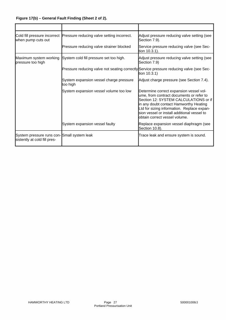
27
Cold fill pressure incorrect when pump cuts out
Pressure reducing valve setting incorrect.
Adjust pressure reducing valve setting (see Section 7.9).
Pressure reducing valve strainer blocked
Service pressure reducing valve (see Sec-tion 10.3.1).
Maximum system working pressure too high
System cold fill pressure set too high.
Adjust pressure reducing valve setting (see Section 7.9)
Pressure reducing valve not seating correctly
Service pressure reducing valve (see Sec-tion 10.3.1)
System expansion vessel charge pressure too high
Adjust charge pressure (see Section 7.4).
System expansion vessel volume too low
Determine correct expansion vessel vol-ume, from contract documents or refer to Section 12: SYSTEM CALCULATIONS or if in any doubt contact Hamworthy Heating Ltd for sizing information. Replace expan-sion vessel or install additional vessel to obtain correct vessel volume.
System expansion vessel faulty
Replace expansion vessel diaphragm (see Section 10.8).
System pressure runs con-sistently at cold fill pres-
Small system leak
Trace leak and ensure system is sound.
Figure 17(b) – General Fault Finding (Sheet 2 of 2).

HAMWORTHY HEATING LTD Page 500001006/J Portland Pressurisation Unit
28
0.069
e = ( 100 - r ) x e + r x ew a a
Maximum system flow temperature ,t (°C)
* Value at maximum system flow temperature ,t
10) Calculated expansion vessel volume ,V
0.35va
Vapour Pressure , p
Water expansion factor ,e
Antifreeze expansion factor ,e
(bar)v
w
9) Expanded volume ,V
x e
= VVv e
= VVe s
=
t =
= (100 -te100
from table below.
a 0.061
f 70
0.023
0
f
0.0680.064
0.029
75
0.026
0
80 82
0
0.031
0
xe -
) x100
+
v -
x
5) System antifreeze content -4) Maximum system working pressure -3) System static head -2) Maximum system water flow temperature -1) System water content -
6) Cold fill pressure ,p
7) Expansion vessel charge pressure ,p
8) Expansion factor ,e
Calculations
- 0.1 =
t
= pcp f
a
+ 0.2 + p= ppf10.2
h v
System Parameters
+ 0.2 +
- 0.1
*t -
*
=*10.2
f -
c -
100
= 0.0519
= 2000 x 0.0519 = 103.8 litres
= 103.8 = 297 litres
0.35
0.040
0.0790.071 0.075
85
0.033
0.10
90
0.35
0.036
0.083 0.087
0.90
0.044
95 100
0.60
105
0.048
1.20
V =v
Ve =
e t =
litres
litres
Vv
Ve
et
120
2.35
0.060
0.0980.090 0.094
110
1.55
0.052
115
0.056
1.90
= 2000 litres
= 22 + 0.2 + 1.20 = 3.56 bar
= 3.56 - 0.1 = 3.46 bar
= (100 - 10) x 0.048 + 10 x 0.087
= 105 °C
= 10 %= 8 bar= 22 m
ra ra%
pc =
pf =
bar
et
pc
bar pf10.2
pp
=w=
h =tVf =s =
Example
metersbar
litres°C
pw
ph
Vst f
= 2000 x 0.08 = 160 litresiVlitres=iVx 0.08x 0.08 =s= ViVfi18) Intermediate expansion vessel volume ,V - (If t < 100 °C)
- 0.35 p = 6.67 - 0.35 = 6.32 barshbar=-0.35 =wa= pshp shp
-sh17) System pressure switch high pressure setting ,p
= 3.56 - 0.3 = 3.26 barslpbar=slp- 0.3- 0.3 =f= pslp
-sl16) System pressure switch low pressure setting ,p
and recalculate from step 11)va> 0.5 then increase expansion vessel volume ,VsIf aNote!
6.67 + 1
= 6.67 - 3.56 = 0.405sa=sa-+ 1+ 1sp
=f- ps= psa
-s15) Expansion vessel acceptance factor at safety valve lift pressure ,a
= 5.97 + 0.7 = 6.67 barspbar=sp+ 0.7+ 0.7 =wa= psp
-s14) Safety valve lift pressure ,p
and recalculate from step 11)vathen increase expansion vessel volume ,Vw> pwaIf pNote!1 - 0.346
= 3.56 + 0.346 = 5.97 barwapbar=wap
1 -+=
va1 - ava+ af= pwap
-
-
-wa13) Actual working pressure ,p
Example continued
= V ava==300
va
va
Vva=
va
avaV
Calculations continued
Vva = 300 litres
e
12) Actual expansion vessel acceptance factor ,a
litres11) Actual fitted expansion vessel volume ,V
a va = 103.8 = 0.346
Figure 18 – Heating System Calculation Sheet.

HAMWORTHY HEATING LTD Page 500001006/J Portland Pressurisation Unit
29
= 0.293
60
9.7+
0.35++ 1
0.35++ 1fp
V
+ 0.35 p = 2.28 + 0.35 = 2.63 barshbar=+0.35 =wa= pshp shp
-sh17) System pressure switch high pressure setting ,p
= 1.67 - 0.3 = 1.37 barslpbar=slp- 0.3- 0.3 =f= pslp
-sl16) System pressure switch low pressure setting ,p
and recalculate from step 11)va> 0.5 then increase expansion vessel volume ,VsIf aNote!
2.98 + 1
= 2.98 - 1.32 = 0.417sa=sa-+ 1+ 1sp
=c- ps= psa
-s15) Expansion vessel acceptance factor at safety valve lift pressure ,a
= 2.28 + 0.7 = 2.98 barspbar=sp+ 0.7+ 0.7 =wa= psp
-s14) Safety valve lift pressure ,p
and recalculate from step 11)vathen increase expansion vessel volume ,Vw> pwaIf pNote!1 - 0.293
= 1.32 + 0.293 = 2.28 barwapbar=wap1 -
+=va1 - ava+ ac= pwap
-
-
-wa13) Actual working pressure ,p
Example continued
= 0.35 ava ==1.67 + 1
va
va
Vva=
va
avaV
Calculations continued
Vva = 60 litres
e
12) Actual expansion vessel acceptance factor ,a
litres11) Actual fitted expansion vessel volume ,V
a va =
-
-
av
v -
vV = V0.35
litres Vv = 9.7 = 27.7 litres=10) Calculated expansion vessel volume ,V
0.35e Vv =
te
**
= 15 m= 3.6 bar= 25 %
= 25 °Cmetersbar%
°C
e = 1000 x 0.0097 = 9.7 litresVlitres=eVxtse =x e= VVe9) Expanded volume ,V
100
e t = 0.0097
100= (100 - 25) x 0.0030 + 25 x 0.0298te
=x+) xt = (100 -e100
aawa x e+ r) x e= ( 100 - rtet8) Expansion factor ,e
= 1.67 - 0.35 = 1.32 barcpbar=cp- 0.35- 0.35 =f= pcp-c7) Expansion vessel charge pressure ,p
10.2= 15 + 0.2 = 1.67 barfpbar=fp+ 0.2
10.210.2hf =+ 0.2= pp
-f6) Cold fill pressure ,pCalculations
= 1000 litres
a
w
h
a
sVtppr
Examplelitres=
====a
whasV
tppr
1) System water content -2) Maximum ambient temperature -3) System static head -4) Maximum system working pressure -5) System antifreeze content -
System Parameters
from table below.a* Value at maximum ambient temperature ,t
aAntifreeze expansion factor ,ewWater expansion factor ,e
aMaximum ambient temperature ,t (°C)
0.03450.03300.03160.02980.02790.02610.02420.02240.02060.01880.0169
0.00520.00440.00370.00300.00240.00180.00140.00100.00070.00030.0002
32.530.027.525.022.520.017.515.012.510.07.5
Figure 19 – Chiller System Calculation Sheet.
HAMWORTHY HEATING LTD Page 500001006/J Portland Pressurisation Unit
30
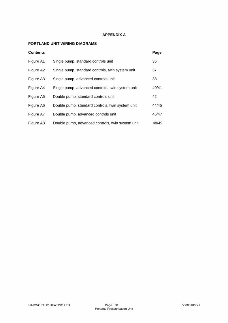
APPENDIX A
PORTLAND UNIT WIRING DIAGRAMS Contents Page Figure A1 Single pump, standard controls unit 36 Figure A2 Single pump, standard controls, twin system unit 37 Figure A3 Single pump, advanced controls unit 38 Figure A4 Single pump, advanced controls, twin system unit 40/41 Figure A5 Double pump, standard controls unit 42 Figure A6 Double pump, standard controls, twin system unit 44/45 Figure A7 Double pump, advanced controls unit 46/47 Figure A8 Double pump, advanced controls, twin system unit 48/49

HAMWORTHY HEATING LTD Page 500001006/J Portland Pressurisation Unit
31
Motor
OverloadRelay
PF1 PumpContactor L 1 21222330 5
Backplate DIN Rail Layout
(grey) (orange) (blue)
R1 6 7 8 9 N N
red
orangered
Overloadgreen
R1a
9 5
orange/black
From Boiler/ChillerSafety Circuit High System Pressure Signal
(If required)
Low System Pressure Signal(If required)
To Boiler/Chiller Safety Circuit
Normal Pressure Signal (If required)
'3'
'2'
'1'
System Pressure Switch
'1'
'2'
8
9
7
6
5
9
- ASCO Pump Pressure Switch Cable Colour
(red)
(blue)
(red)(black)
- Pump Contactor Terminal- Terminal on Backplate DIN Rail
Key:-
blue
brownN
M6Pump Contactor and Overload1
redPF1
0.75mm²
30Water LevelFloat Switch1
cno
nc
cnc
no'3'
'4'
'5'
'6'
R1 1413
2
41 23
2221
Pump PressureSwitch
red 16/0.2 (0.5mm²)L 1F2A
9695 A2A1 P1N
red
Pump
Low WaterRelay
PumpContactor
Panel LiveN
Figure A1 – Wiring Diagram – Single Pump, Standard Controls Unit.

HAMWORTHY HEATING LTD Page 500001006/J Portland Pressurisation Unit
32
red
Motor
9B
8B
7B
6B
(orange)
5B
OverloadRelay
PF1 PumpContactor L 1 2122 23 30 5
A
Backplate DIN Rail Layout
(grey) (orange) (blue)
R1 6A
7A
8A
9A
N N
red
orangered
Overloadgreen
R1a
9 5
orange/black
From Boiler/ChillerSafety Circuit
From Boiler/ChillerSafety Circuit
System 'B'
System 'A'
To Boiler/Chiller Safety Circuit
Low System Pressure Signal(If required)
High System Pressure Signal(If required)
High System Pressure Signal(If required)
Low System Pressure Signal(If required)
To Boiler/Chiller Safety Circuit
Normal Pressure Signal (If required)
'3'
'2''1'
System 'B' Pressure Switch
System 'A' Pressure Switch
'1'
'2'
'1'
'2'
5B
9B
8B
9B
7B
6B
8A
9A
7A
6A
5A
9A
'6'
'5'
'4'
'3'no
nc
c
c
nc
no
- ASCO Pump Pressure Switch Cable Colour
(red)
(blue)
(red)(black)
- Pump Contactor Terminal- Terminal on Backplate DIN Rail
Key:-
blue
brownN
M6Pump Contactor and Overload1
redPF1
0.75mm²
30Water LevelFloat Switch1
cno
nc
cnc
no'3'
'4'
'5'
'6'
R1 1413
2
41 23
2221
Pump PressureSwitch
red 16/0.2 (0.5mm²)L 1F2A
9695 A2A1 P1N
Pump
Low WaterRelay
PumpContactor
Panel LiveN
Figure A2 – Wiring Diagram – Single Pump, Standard Controls, Twin System

HAMWORTHY HEATING LTD Page 500001006/J Portland Pressurisation Unit
33
1413
Motor Overload
'3'
'2''1'
(blue)
(double) (grey)
(yellow)(orange)(grey)
Fascia DIN Rail LayoutBackplate DIN Rail Layout
PF1
OverloadRelay
PumpContactor 1817161514138765111L 30272522
28262321
NNN R4R3R2R1
High PressureLow Pressure
100K
100K
green
1
- ASCO Pump Pressure Switch Cable Colour
(red)
(blue)
(red)(black)
- Pump Contactor Terminal
- Terminal on Backplate DIN Rail
Key:-
bluebrown
NM
6Pump Contactor and Overload1red
PF10.75mm²
white/red
Pump Aux.Contact
Hrs. Run Meteryellow
19
59R4a
R4 1413red/brown
1a1
MuteButton
orange/red210
R3b
30Water LevelFloat Switch1
cno
nc'1'
'2'c
nc
no'3'
'4'
'5'
'6'
1
System 'A'PressureSwitch
28
27
26
25
grey/blue
green/red
yellow
white
R3red1413
R2red
1413
red1413 R1
green
greengrey
2
4
1 23
2221
Pump Pressure Switch
red 16/0.2 (0.5mm²)L 1F2A
R2bR3b
610610red grey red
23
1
OffHand
greenSW1a9695 A2A1 P1
N
red
Pump
Low WaterBuzzer
Mute Relay
Low Water
Low WaterRelay
High SystePressure
Low SystemPressure
NormalPressure
PumpRunning
PumpContactor
Panel LiveN
311
R1c
R3c
Low Water311
311
R2c
8125959
R3dR2aR1a
Boiler Safety Circuit
610
R1b
Chiller Safety Circuit
1413 87
6518171615
Figure A3 – Wiring Diagram – Single Pump, Advanced Controls Unit.
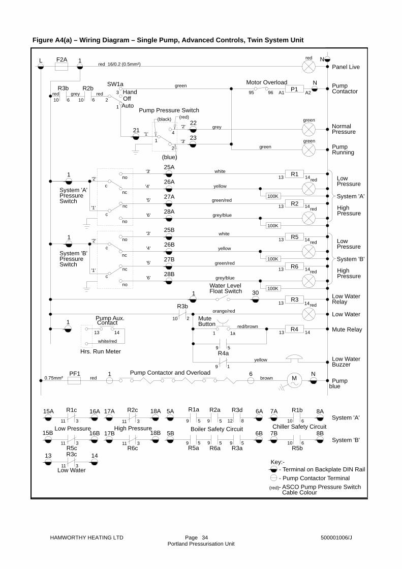
HAMWORTHY HEATING LTD Page 500001006/J Portland Pressurisation Unit
34
Motor Overload
Auto
'1''3'
'2'
1413
100K
100K
100K
100K
green
1
- ASCO Pump Pressure Switch Cable Colour
(red)
(blue)
(red)(black)
- Pump Contactor Terminal- Terminal on Backplate DIN Rail
Key:-
bluebrown
NM
6Pump Contactor and Overload1red
PF1
white/red
Pump Aux.Contact
Hrs. Run Meteryellow
19
59R4a
R4 1413red/brown
1a1
MuteButton
orange/red210
R3b
30Water LevelFloat Switch1
cno
nc'1'
'2'c
nc
no'3'
'4'
'5'
'6'
1
System 'A'PressureSwitch
System 'B'PressureSwitch
1
c
no
nc'1'
'2'c
nc
no'3'
'4'
'5'
'6'28B
27B
26B
25B
28A
27A
26A
25A
grey/blue
green/red
yellow
white
grey/blue
green/red
yellow
white
R3red1413
red1413 R6
R5red1413
R2red1413
red1413 R1
green
greengrey
2
4
1 23
2221
Pump Pressure Switch
red 16/0.2 (0.5mm²)L 1F2A
R2bR3b
610610red grey red
23
1
OffHand
greenSW1a9695 A2A1 P1
N
red
Pump
Low WaterBuzzer
Mute Relay
Low Water
Low WaterRelay
System 'B'
LowPressure
HighPressure
HighPressure
LowPressure
System 'A'
NormalPressure
PumpRunning
PumpContactor
Panel LiveN
311
311R5c
R1c
Low Pressure
R3c
Low Water311
311
311
R6c
R2c
High Pressure
595959
8125959
R3aR6aR5a
R3dR2aR1a
Boiler Safety Circuit
610
610
R5b
R1b
Chiller Safety Circuit
System 'B'
System 'A'
1413
8B
8A
7B
7A
6B
6A
5B
5A
18B
18A
17B
17A
16B15B
16A15A
Figure A4(a) – Wiring Diagram – Single Pump, Advanced Controls, Twin System Unit
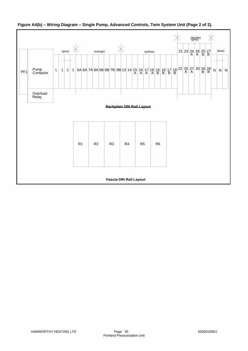
HAMWORTHY HEATING LTD Page 500001006/J Portland Pressurisation Unit
35
BBAA
BBAA
28
27
26
25
BBBBAAAA181716158B7B6B5B
R6R5
PF1
R1
Backplate DIN Rail Layout
Fascia DIN Rail Layout
R2 R3 R4
13 14 15 16 17 18PumpContactor
N
(grey) (orange) (yellow)
(double) (grey)
(blue)
N N
21 23 26 28
22 25 27 30L 1 1 1 5A 6A 7A 8A
OverloadRelay
Figure A4(b) – Wiring Diagram – Single Pump, Advanced Controls, Twin System Unit (Page 2 of 2).
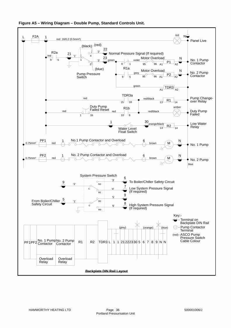
HAMWORTHY HEATING LTD Page 500001006/J Portland Pressurisation Unit
36
Figure A5 – Wiring Diagram – Double Pump, Standard Controls Unit.
TDR3PF1 No. 2 PumpContactor
OverloadRelay
OverloadRelay
PF2 6 7 8 9 N NNo. 1 PumpContactor L 1 1 21 2223 30 5
(grey) (orange) (blue)
R1
Backplate DIN Rail Layout
R2
red
red
Motor Overload
Motor Overload
green
green
grey
violet
R2a
9 5
red/black
orange/black
From Boiler/ChillerSafety Circuit High System Pressure Signal
(If required)
Low System Pressure Signal(If required)
To Boiler/Chiller Safety Circuit
Normal Pressure Signal (If required)
'3'
'2''1'
System Pressure Switch
'1'
'2'
8
9
7
6
5
9
59
19
R1a
- ASCO Pump Pressure Switch Cable Colour
(red)
(blue)
(red)(black)
red/black
- Pump Contactor Terminal
- Terminal on Backplate DIN Rail
Key:-
blue
brown
brown
N
N
M
M
6
6
No. 2 Pump Contactor and Overload
No.1 Pump Contactor and Overload
1
1
red
red
PF2
PF1
0.75mm²
0.75mm²
30
Water LevelFloat Switch
1
cno
nc
cnc
no'3'
'4'
'5'
'6'
R21413
red1b1
Duty PumpFailed Reset
R1
amber
1413
610
1815
R1b
TDR3ared
TDR3A2A1
2
41 23
2221
Pump PressureSwitch
red 16/0.2 (0.5mm²)L 1F2A
9695
9695
A2A1
A2A1
NP2
P1N
red
No. 2 Pump
No. 1 Pump
Low WaterRelay
Duty PumpFailed
Pump Change-over Relay
No. 2 PumpContactor
No. 1 PumpContactor
Panel LiveN
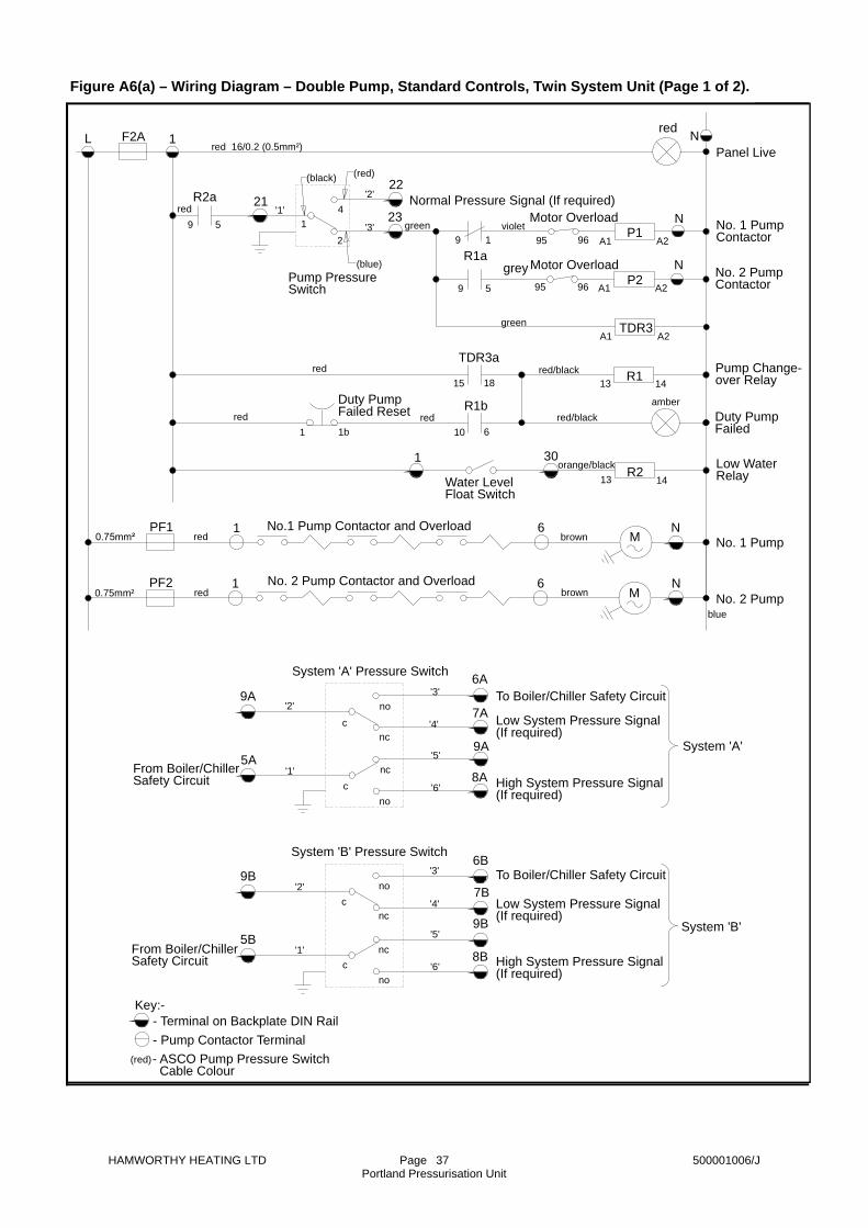
HAMWORTHY HEATING LTD Page 500001006/J Portland Pressurisation Unit
37
red
red
Motor Overload
Motor Overload
green
green
grey
violet
R2a
9 5
red/black
orange/black
From Boiler/ChillerSafety Circuit
From Boiler/ChillerSafety Circuit
System 'B'
System 'A'
To Boiler/Chiller Safety Circuit
Low System Pressure Signal(If required)
High System Pressure Signal(If required)
High System Pressure Signal(If required)
Low System Pressure Signal(If required)
To Boiler/Chiller Safety Circuit
Normal Pressure Signal (If required)
'3'
'2''1'
System 'B' Pressure Switch
System 'A' Pressure Switch
'1'
'2'
'1'
'2'
5B
9B
8B
9B
7B
6B
8A
9A
7A
6A
5A
9A
'6'
'5'
'4'
'3'no
nc
c
c
nc
no
59
19
R1a
- ASCO Pump Pressure Switch Cable Colour
(red)
(blue)
(red)(black)
red/black
- Pump Contactor Terminal- Terminal on Backplate DIN Rail
Key:-
blue
brown
brown
N
N
M
M
6
6
No. 2 Pump Contactor and Overload
No.1 Pump Contactor and Overload
1
1
red
red
PF2
PF1
0.75mm²
30
Water LevelFloat Switch
1
cno
nc
cnc
no'3'
'4'
'5'
'6'
R21413
red1b1
Duty PumpFailed Reset
R1
amber
1413
610
1815
R1b
TDR3ared
TDR3A2A1
2
41 23
2221
Pump PressureSwitch
red 16/0.2 (0.5mm²)L 1F2A
9695
9695
A2A1
A2A1
NP2
P1N
red
No. 2 Pump
No. 1 Pump
Low WaterRelay
Duty PumpFailed
Pump Change-over Relay
No. 2 PumpContactor
No. 1 PumpContactor
Panel LiveN
Figure A6(a) – Wiring Diagram – Double Pump, Standard Controls, Twin System Unit (Page 1 of 2).

HAMWORTHY HEATING LTD Page 500001006/J Portland Pressurisation Unit
38
9B
9A
24232221
TDR3
6B
5B
PF2
OverloadRelay
No. 1PumpContactor
R1
Backplate DIN Rail Layout
Fascia DIN Rail Layout
R2
7B
8B
No. 2 PumpContactor
(grey) (orange) (orange) (blue)
N NL 1 1 5A
6A
7A
8A
OverloadRelay
PF1
Figure A6(b) – Wiring Diagram – Double Pump, Standard Controls, Twin System Unit (Page 2 of 2).

HAMWORTHY HEATING LTD Page 500001006/J Portland Pressurisation Unit
39
'3'
'2''1'
Motor Overload
Motor Overload
14131413
100K
100K
1
- ASCO Pump Pressure Switch Cable Colour
(red)
(blue)
(red)(black)
red/black
- Pump Contactor Terminal- Terminal on Backplate DIN Rail
Key:-
bluebrown
brown
N
N
M
M
6
6
No. 2 Pump Contactor and Overload
No.1 Pump Contactor and Overload
1
1
red
red
PF2
PF1
0.75mm²
0.75mm²
white/redwhite/red
Hrs. Run Meter
No. 2 PumpAux. Contact
No. 1 PumpAux. Contact
Hrs. Run Meteryellow
19
59R6a
R61413
red/brown1a1
MuteButton
orange/red210
R5b
30Water LevelFloat Switch
1
cno
nc'1'
'2'c
nc
no'3'
'4'
'5'
'6'
1
SystemPressureSwitch
28
27
26
25
grey/blue
green/red
yellow
white
R5red1413
R4red1413
red1413 R3
red1b1
Duty PumpFailed Reset
R2amber1413
711
1815
R2c
TDR1aredTDR1 A2A1
green
6
SW2b
violet
610
210R2b
R2a7
5grey
59
19
brown
orange
green
green
greengrey
2
41 23
2221
PumpPressureSwitch
red 16/0.2 (0.5mm²)L 1F2A
R4bR5b
610610red grey red
2
3
1 AutoOffHand
pinkSW1aSW2a
23
1No. 2 Pump
No. 1 Pump
brown
orange
9695
9695
A2A1
A2A1N
P2
P1N
red
No. 2 Pump
No. 1 Pump
Low WaterBuzzer
Mute Relay
Low Water
Low WaterRelay
High SystemPressure
Low SystemPressure
Duty PumpFailed
Pump Change-over Relay
NormalPressure
No. 2 PumpRunning
No. 1 PumpRunning
No. 2 PumpContactor
No. 1 PumpContactor
Panel LiveN
311
812
R2d
Duty Pump Failed
R3c
Low Pressure
R5c
Low Water311
311
R4c
High Pressure8125959
R5dR4aR3a
Boiler Safety Circuit
610
R3b
Chiller Safety Circuit
14131211 87
6518171615
Figure A7(a) – Wiring Diagram – Double Pump, Advanced Controls Unit (Page 1 of 2).
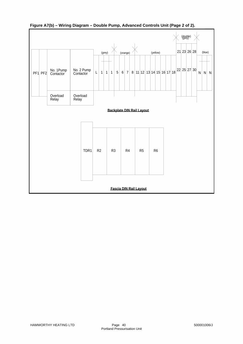
HAMWORTHY HEATING LTD Page 500001006/J Portland Pressurisation Unit
40
TDR1 R6
1211PF2
OverloadRelay
No. 1PumpContactor
R2
Backplate DIN Rail Layout
Fascia DIN Rail Layout
R3 R4 R5
13 14 15 16 17 18No. 2 PumpContactor N
(grey) (orange) (yellow)
(double) (grey)
(blue)
N N
21 23 26 28
22 25 27 30L 1 1 1 5 6 7 8
OverloadRelay
PF1
Figure A7(b) – Wiring Diagram – Double Pump, Advanced Controls Unit (Page 2 of 2).

HAMWORTHY HEATING LTD Page 500001006/J Portland Pressurisation Unit
41
Motor Overload
Motor Overload
'1''3'
'2'
14131413
100K
100K
100K
100K
1
- ASCO Pump Pressure Switch Cable Colour
(red)
(blue)
(red)(black)
red/black
- Pump Contactor Terminal- Terminal on Backplate DIN Rail
Key:-
blue
brown
brown
N
N
M
M
6
6
No. 2 Pump Contactor and Overload
No.1 Pump Contactor and Overload
1
1
red
red
PF2
PF1
0.75mm²
0.75mm²
white/redwhite/red
Hrs. Run Meter
No. 2 PumpAux. Contact
No. 1 PumpAux. Contact
Hrs. Run Meteryellow
19
59R6a
R61413
red/brown1a1
MuteButton
orange/red210
R5b
30
Float Switch
Water Level1
cno
nc'1'
'2'c
nc
no'3'
'4'
'5'
'6'
1
System 'A'PressureSwitch
System 'B'PressureSwitch
1
c
no
nc'1'
'2'c
nc
no'3'
'4'
'5'
'6'28B
27B
26B
25B
28A
27A
26A
25A
grey/blue
green/red
yellow
white
grey/blue
green/red
yellow
white
R5red1413
red1413 R8
R7red1413
R4red1413
red1413R3
red1b1
Duty PumpFailed Reset
R2amber1413
711
1815R2c
TDR1ared
TDR1A2A1
green
6
SW2b
violet
610
210R2b
R2a7
5grey
59
19
brown
orange
green
green
greengrey
2
41 23
2221
PumpPressureSwitch
red 16/0.2 (0.5mm²)L 1F2A
R4bR5b
610610red grey red
23
1
AutoOffHand
pinkSW1aSW2a
23
1No. 2 Pump
No. 1 Pump
brown
orange
9695
9695
A2A1
A2A1N
P2
P1N
red
No. 2 Pump
No. 1 Pump
Low WaterBuzzer
Mute Relay
Low Water
Low WaterRelay
System 'B'
LowPressure
HighPressure
HighPressure
LowPressure
System 'A'
Duty PumpFailed
Pump Change-over Relay
NormalPressure
No. 2 PumpRunning
No. 1 PumpRunning
No. 2 PumpContactor
No. 1 PumpContactor
Panel LiveN
311
311
812
R2d
Duty Pump Failed
R7c
R3c
Low Pressure
R5c
Low Water311
311
311
R8c
R4c
High Pressure
595959
8125959
R5aR8aR7a
R5dR4aR3a
Boiler Safety Circuit
610
610
R7b
R3b
Chiller Safety Circuit
System 'B'
System 'A'
14131211
8B
8A
7B
7A
6B
6A
5B
5A
18B
18A
17B
17A
16B15B
16A15A
Figure A8(a) – Wiring Diagram – Double Pump, Advanced Controls, Twin System Unit (Page 1

HAMWORTHY HEATING LTD Page 500001006/J Portland Pressurisation Unit
42
BB
AA
BB
AA
2827
2625
BB
BB
AA
AA
1817
1615
8B7B
6B5B
R8
R7
TDR
1R
61211
PF2
Ove
rload
Rel
ay
No.
1P
ump
Con
tact
or
R2
Bac
kpla
te D
IN R
ail L
ayou
t
Fasc
ia D
IN R
ail L
ayou
t
R3
R4
R5
1314
1516
1718
No.
2 P
ump
Con
tact
orN
(gre
y)(o
rang
e)(y
ello
w)
(dou
ble)
(gre
y)
(blu
e)
NN
2123
2628
2225
2730
L1
11
5A6A
7A8A
Ove
rload
Rel
ay
PF1
Figure A8(b) – Wiring Diagram – Double Pump, Advanced Controls, Twin System Unit (Page 2 of 2).

HAMWORTHY HEATING LTD Page 500001006/J Portland Pressurisation Unit
43
NOTES

HAMWORTHY HEATING LTD Page 500001006/J Portland Pressurisation Unit
44
NOTES

HAMWORTHY HEATING LTD Page 500001006/J Portland Pressurisation Unit
45
NOTES

Notes

Poole OfficeHamworthy Heating Limited
Fleets Corner, Poole, Dorset BH17 0HH England
Main switchboard tel: 01202 662500
Technical enquiries 01202 662527/662528 01202 665111
Spare parts 01202 662525 01202 665111
Service department 01202 662555 01202 662522
Birmingham OfficeHamworthy Heating Limited
Shady Lane, Great Barr, Birmingham B44 9ER
Main switchboard tel: 0121 360 7000 fax: 0121 325 2309
General enquiries 0121 360 7000• flue components
• packaged fan dilution systems
• bespoke flue components
• bespoke flue systems
• design and installation
Customer Services
Associate Companies, Offices and Agents throughout the World.
Hamworthy reserves the right to make changes and improvements which may necessitate alteration to the specification without prior notice.
Connect directDirect Dial Telephone and Fax Numbers
Direct Email Addresses
Hamworthy Heating Accredited Agents
Website
www.hamworthy-heating.com
• boilers
• controllers
• water heaters
• pressurisation sets
North West England
Gillies Modular Services
210-218 New Chester Road, Birkenhead, Merseyside L41 9BG
tel: 0151 666 1030 fax: 0151 647 8101
Scotland
McDowall Modular Services
14-46 Lomond Street, Glasgow, Scotland G22 6JD
tel: 0141 336 8795 fax: 0141 336 8954
Southern Ireland
HEVAC Limited
Naas Road, Dublin 12, Ireland
tel: 00 3531 141 91919 fax: 00 3531 145 84806
Northern Ireland
HVAC Supplies Limited
Unit 2, Antrim Line Business Park, Sentry Lane, Newtownabbey BT36 8XX
tel: 02890 849826 fax: 02890 847443
North East England
Allison Heating Products
17 Beech Road, South Shields, Tyne & Wear NE33 2QH
tel: 0191 455 7898 fax: 0191 455 7899


