

Reduced byUp to approx. 90 %
∗Air
consumption
Up to approx. twice∗
High flow rate
Reduced by up to approx. 27 %∗
Lightweight
Digital pressure switch standardised
Space savingNew structure without fixed throttle does not require a mist separator.
MistSeparator
Air Filter
Air Filter
(For IR2000-A)
PrecisionRegulator
PrecisionRegulator
Reduced
71 mm
Current model
Sensitivity: 0.2 % (Full span)
Repeatability: ±0.5 % (Full span)
∗ Compared with the current IR1000/2000/3000
Series Current model NewNew IR
IR1000-A 0.14 0.13IR2000-A 0.30 0.23IR3000-A 0.64 0.47
[kg]
∗ Compared with the current IR1000/2000
Series Current model NewNew IR
IR1000-A 320 720IR2000-A 940 1900
[l/min (ANR)]
∗ Compared with the current IR1000/2000/3000
Series Current model NewNew IR
IR1000-A/IR2000-A 4.4 1 or lessIR3000-A 11.5 1 or less
[l/min (ANR)]
RoHS
NewNew
CAT.EUS60-22A-UK
Series IR1000-A/2000-A/3000-A
Precision Regulator
0 10 20 30 40 500
600
300
1200
900
1800
1500
600
300
1200
900
1800
1500
0 10 20 30 40 500
OUTIN (SUP.)
Fixedthrottle
OUTIN (SUP.)
0 720320
0.1
0.2
0.3
0.4
Approx.
twice
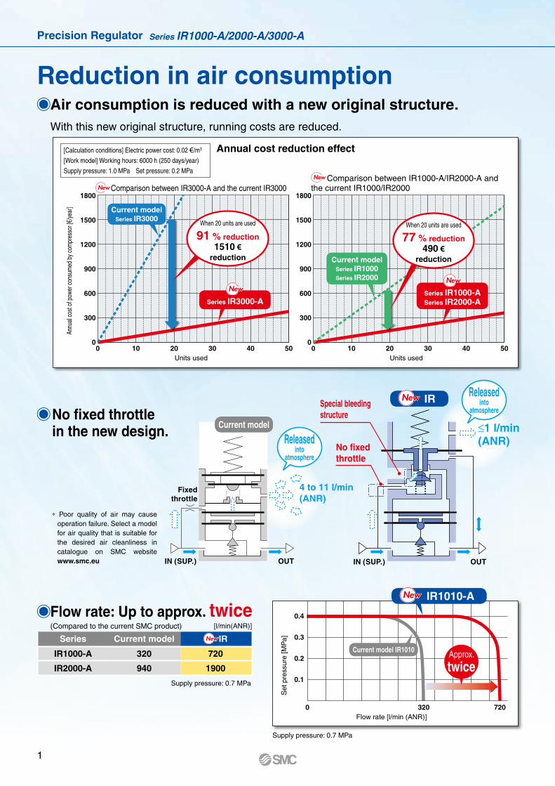
Reduction in air consumption Air consumption is reduced with a new original structure. With this new original structure, running costs are reduced.
No fixed throttle in the new design.
Flow rate: Up to approx. twice (Compared to the current SMC product)
* Poor quality of air may cause operation failure. Select a model for air quality that is suitable for the desired air cleanliness in catalogue on SMC website www.smc.eu
Supply pressure: 0.7 MPa
Supply pressure: 0.7 MPa
[Calculation conditions] Electric power cost: 0.02 €/m3
[Work model] Working hours: 6000 h (250 days/year)
Supply pressure: 1.0 MPa Set pressure: 0.2 MPa
Series Current model NewNew IR
IR1000-A 320 720
IR2000-A 940 1900
Annual cost reduction effect
Comparison between IR3000-A and the current IR3000Comparison between IR1000-A/IR2000-A and
the current IR1000/IR2000
Annu
al co
st of
pow
er co
nsum
ed b
y com
pres
sor [
€/ye
ar]
Units usedUnits used
IRNewNew
IR1010-ANewNew
Current model
Releasedinto
atmosphere
Releasedinto
atmosphere
≤1 l/min(ANR)
4 to 11 l/min (ANR)
Flow rate [l/min (ANR)]
Set
pre
ssur
e [M
Pa]
Current model IR1010
Special bleedingstructure
No fixedthrottle
When 20 units are used
91 % reduction1510 €
reduction
Series IR3000-A
When 20 units are used
77 % reduction490 €
reduction
Current modelSeries IR3000
NewNew
Current modelSeries IR1000Series IR2000
Series IR1000-ASeries IR2000-A
NewNew
[l/min(ANR)]
NewNew
NewNew
1
Precision Regulator Series IR1000-A/2000-A/3000-A

EXH EXH
ININ IN
OUTOUT OUTEXH
Exhaust (EXH) directions can be selected. (Series IR3000-A)
Bottom and front exhaust added.
Hexagon panel nut mounting∗ Interchangeable with the current SMC product
Sensitivity: 0.2 % (Full span)
Repeatability: ±0.5 % (Full span)
WeightReduced by up to approx. 27 %
Mounting is interchangeable
with the current SMC model.
Pressure
gauge
Digital pressure switch
standardised
[kg]
Series Current model NewNew IR
IR1000-A 0.14 0.13
IR2000-A 0.30 0.23
IR3000-A 0.64 0.47
Hexagon panel nut
(Option)
Note) The set pressure may vary depending on the elapsed time
and change in ambient temperature after pressure setting. If
the setting value varies, adjust the pressure with the knob.
Bottom
exhaust
Front
exhaust
Rear
exhaust
New IR can be used between a cylinder and solenoid valve.
NewNew
2
Precision Regulator Series IR1000-A/2000-A/3000-A

Application Examples
Constant fl uid pressure Note)
� As there is a large effective area for supply and
exhaust pressure, setting can be done quickly.
TANK
Balance and drive
Accurate balance pressure setting Note)
� Limits pressure fl uctuation when driving a cylinder,
maintaining excellent static and dynamic balance.
Multistage control of pressing force for workpiece
(Wrapping machine) Note)
Accurate pressure setting
Sensitivity within 0.2 % F.S. (Full Span)
Tension control Note)
Contact pressure control Note)
� Adapts to the cylinder’s piston displacement,
maintaining a constant pressure.
Leak test circuit Note)
Residual pressure relief Note)
�Residual pressure is exhausted by relief function.
Ex.) Backfl ow from the tank
Usage between a cylinder and solenoid valve Note)
�It can be used between a cylinder and a solenoid valve.
Ex.) Between a cylinder and solenoid valve
3
Precision Regulator Series IR1000-A/2000-A/3000-A

Series Variations
Model Set pressure range (MPa) Port size
IR1000-A
IR1010-A
IR1020-A
0.005 to 0.2
0.01 to 0.4
0.01 to 0.8
1/8
IR1000-A
IR2000-A
IR2010-A
IR2020-A
0.005 to 0.2
0.01 to 0.4
0.01 to 0.8
1/4
IR2000-A
IR3000-A
IR3010-A
IR3020-A
0.01 to 0.2
0.01 to 0.4
0.01 to 0.8
1/4, 3/8, 1/2
IR3000-A
Series
Basic
Type (
Knob)
Adjustment of blow-line pressure Note)
� Outlet pressure is less affected by fl uctuation of inlet
pressure. New IR offers consistent pressure control.
Note) The set pressure may vary depending on the elapsed time and
change in ambient temperature after pressure setting. If the setting
value varies, adjust the pressure with the knob.
4
Precision Regulator Series IR1000-A/2000-A/3000-A

Standard Specifi cations
Accessories (Option)/Part No.
Note 1) When there is no fl ow rate on the outlet.
Note 2) Other characteristics such as aging deterioration and temperature
characteristics are not included.
Note 3) Measuring conditions: supply pressure 1.0 MPa, set pressure 0.2
MPa
Note 4) –5 to 50° C for the products with the digital pressure switch
Note 5) Without accessories
Note 1) This is an assembly of the bracket and resin panel nut.Note 2) � in part numbers for a round type pressure gauge indicates a
type of connection thread. No indication is necessary for R;
however, indicate N for NPT.
A 1.0 MPa pressure gauge is fi tted for 0.8 MPa setting.
Please contact SMC regarding the supply of pressure gauge with
psi unit specifi cations.
Note 3) � in part numbers for a digital pressure switch indicates a type of
connection thread. No indication is necessary for R; however,
indicate N for NPT. For details on handling digital pressure switch
and specifi cations, refer to the WEB catalogue on www.smc.eu.
Please contact SMC regarding the supply of digital pressure
switch with unit conversion function.
Modular Products and Accessories
Refer to the WEB catalogue for details of the modular applicable products
and accessories. The former modular and mounting brackets can be used.
Applicable products
and accessories
Applicable size
Series IR1000-A Series IR2000-A Series IR3000-A
Filter AF20-A AF30-A AF40-A
Spacer Y200-A Y300-A Y400-A
Spacer with bracket Y200T-A Y300T-A Y400T-A
Description IR10�0-A IR20�0-A IR30�0-A
Bracket assembly Note 1) IR10P-501AS IR20P-501AS IR30P-501AS
Hexagon panel nut IR10P-600S IR20P-600S IR20P-600S
Round type
pressure
gauge Note 2)
0.2 MPa setting G33-2-�01 G43-2-�01 G43-2-�01
0.4 MPa setting G33-4-�01 G43-4-�01 G43-4-�01
0.8 MPa setting G33-10-�01 G43-10-�01 G43-10-�01
Digital
pressure
switch Note 3)
NPN 1 output ISE30A-�01-N-ML
PNP 1 output ISE30A-�01-P-ML
NPN 1 output/Voltage output ISE30A-�01-C-ML
NPN 1 output/Current output ISE30A-�01-D-ML
ModelBasic type (Knob)
IR10�0-A IR20�0-A IR30�0-A
Fluid Air
Proof pressure 1.5 MPa
Max. supply pressure 1.0 MPa
Min. supply pressure Note 1) Set pressure + 0.05 MPa Set pressure + 0.1 MPa
Set pressure range
IR1000-A: 0.005 to 0.2 MPa IR2000-A: 0.005 to 0.2 MPa IR3000-A: 0.01 to 0.2 MPa
IR1010-A: 0.01 to 0.4 MPa IR2010-A: 0.01 to 0.4 MPa IR3010-A: 0.01 to 0.4 MPa
IR1020-A: 0.01 to 0.8 MPa IR2020-A: 0.01 to 0.8 MPa IR3020-A: 0.01 to 0.8 MPa
Sensitivity Within 0.2 % of full span
Repeatability Note 2) Within ±0.5 % of full span
Air consumption Note 3) 1 l/min (ANR) or less
Port size 1/8 1/4 1/4, 3/8, 1/2
Pressure gauge port 1/8 (2 locations)
Ambient and fluid temperature Note 4) −5 to 60° C (No freezing)
Weight [kg] Note 5) 0.13 0.23 0.47
Precision RegulatorSeries IR1000-A/2000-A/3000-A
Basic type
(Knob)
Symbol
5

How to Order
00 0IR 1 01 BG
Symbol Descriptionq
Body size1 2 3
w Set pressure range0
0.005 to 0.2 MPa V V —0.01 to 0.2 MPa — — V
1 0.01 to 0.4 MPa V V V
2 0.01 to 0.8 MPa V V V
+
e Exhaust direction0 Bottom exhaust V V V
1 Front exhaust — — V
2 Rear exhaust — — V
+
r Pipe thread type— Rc V V V
N NPT V V V
F G V V V
+
t Port size
01 1/8 V — —02 1/4 — V V
03 3/8 — — V
04 1/2 — — V
+
y
Opt
ion
Not
e 1)
a Mounting— Without mounting option V V V
B Note 2) With bracket V V V
H With hexagon panel nut (for panel mount) V V V
+
b Pressure gauge— Without pressure gauge V V V
G Round type pressure gauge V V V
cWith digital
pressure switch
EA NPN open collector 1 output V V V
EB PNP open collector 1 output V V V
EC NPN open collector 1 output + Analogue voltage output V V V
ED NPN open collector 1 output + Analogue current output V V V
+
u
Sem
i-sta
ndar
d
d Flow direction— Flow direction: Left to right V V V
R Flow direction: Right to left V V V
+
e Knob— Upward V V V
V Downward V V V
+
f Pressure unit Note 3)
— Name plate and pressure gauge in imperial units: MPa V V V
Z Name plate and pressure gauge in imperial units: psi V V V
ZA Digital pressure switch: With unit conversion function V V V
Pipe thread type
Name plate in imperial units
Pressure gauge in imperial units
G EA, EB, EC, ED
—Rc
MPa MPa Fixed SI unitNPTG
Z Note 4)
Rc — — —
NPT psi psiWith unit conversion function
(Initial value psi)G — — —
ZA Note 5)
RcMPa —
With unit conversion function
NPTG
• Option/Semi-standard: Select one each for a to f. Options b and c cannot be selected together.• Option/Semi-standard symbol: When more than one specification is required, indicate in alphanumeric order.
r t y uewq
A
Note 1) Options are shipped together with the product, but not assembled. B and H cannot be selected at the same time. The current bracket cannot be used for this product.
Note 2) Assembly of a bracket and set nuts.Note 3) See pressure unit table below.
Note 4) For pipe thread type: NPTNote 5) For options: EA, EB, EC, ED
6
Precision Regulator Series IR1000-A/2000-A/3000-A

Flow rate [l/min (ANR)]
Set
pre
ssur
e [M
Pa]
0.7
0.6
0.5
0.4
0.3
0.2
0.1
00 200 400 600 800
Flow rate [l/min (ANR)]
Set
pre
ssur
e [M
Pa]
0.7
0.6
0.5
0.4
0.3
0.2
0.1
0050100150200
0.210
0.205
0.200
0.195
0.1900.2 0.3 0.4 0.5 0.6 0.7 0.8 0.9 1.0 1.1
Set point
Supply pressure [MPa]
Set
pre
ssur
e [M
Pa]
0.210
0.205
0.200
0.195
0.1900.2 0.3 0.4 0.5 0.6 0.7 0.8 0.9 1.0 1.1
Supply pressure [MPa]
Set
pre
ssur
e [M
Pa]
Set point
0.210
0.205
0.200
0.195
0.1900.2 0.3 0.4 0.5 0.6 0.7 0.8 0.9 1.0 1.1
Supply pressure [MPa]
Set
pre
ssur
e [M
Pa]
Set point
Series IR1000-A
IR1020-01-A Supply pressure: 0.7 MPa IR1020-01-A Back pressure: 0.7 MPa
IR1000-A
IR1010-A
IR1020-A
Supply pressure: 0.3 to 1.0 MPaSet pressure: 0.2 MPa
Flow rate: 0 l/min (ANR)
Supply pressure: 0.3 to 1.0 MPaSet pressure: 0.2 MPa
Flow rate: 0 l/min (ANR)
Supply pressure: 0.3 to 1.0 MPaSet pressure: 0.2 MPa
Flow rate: 0 l/min (ANR)
Flow-rate Characteristics Relief Characteristics
Pressure Characteristics
∗ The data shown below are representative values, and are not guaranteed.
7
Series IR1000-A/2000-A/3000-A

0.7
0.6
0.5
0.4
0.3
0.2
0.1
00 500 1000 1500 2000
Flow rate [l/min (ANR)]
Set
pre
ssur
e [M
Pa]
0.7
0.6
0.5
0.4
0.3
0.2
0.1
00150300450600
Flow rate [l/min (ANR)]
Set
pre
ssur
e [M
Pa]
0.210
0.205
0.200
0.195
0.1900.2 0.3 0.4 0.5 0.6 0.7 0.8 0.9 1.0 1.1
Supply pressure [MPa]
Set
pre
ssur
e [M
Pa]
Set point
0.210
0.205
0.200
0.195
0.1900.2 0.3 0.4 0.5 0.6 0.7 0.8 0.9 1.0 1.1
Supply pressure [MPa]
Set
pre
ssur
e [M
Pa]
Set point
0.210
0.205
0.200
0.195
0.1900.2 0.3 0.4 0.5 0.6 0.7 0.8 0.9 1.0 1.1
Supply pressure [MPa]
Set
pre
ssur
e [M
Pa]
Set point
Series IR2000-A
IR2020-02-A Supply pressure: 0.7 MPa IR2020-02-A Back pressure: 0.7 MPa
IR2000-A
IR2010-A
IR2020-A
Flow-rate Characteristics Relief Characteristics
Pressure Characteristics
∗ The data shown below are representative values, and are not guaranteed.
Supply pressure: 0.3 to 1.0 MPaSet pressure: 0.2 MPa
Flow rate: 0 l/min (ANR)
Supply pressure: 0.3 to 1.0 MPaSet pressure: 0.2 MPa
Flow rate: 0 l/min (ANR)
Supply pressure: 0.3 to 1.0 MPaSet pressure: 0.2 MPa
Flow rate: 0 l/min (ANR)
8
Precision Regulator Series IR1000-A/2000-A/3000-A

0.7
0.6
0.5
0.4
0.3
0.2
0.1
00 1000 2000 3000 4000 5000 6000
Flow rate [l/min (ANR)]
Set
pre
ssur
e [M
Pa]
0.7
0.6
0.5
0.4
0.3
0.2
0.1
0010002000300040005000
Flow rate [l/min (ANR)]
Set
pre
ssur
e [M
Pa]
0.210
0.205
0.200
0.195
0.1900.2 0.3 0.4 0.5 0.6 0.7 0.8 0.9 1.0 1.1
Supply pressure [MPa]
Set
pre
ssur
e [M
Pa]
Set point
0.210
0.205
0.200
0.195
0.1900.2 0.3 0.4 0.5 0.6 0.7 0.8 0.9 1.0 1.1
Supply pressure [MPa]
Set
pre
ssur
e [M
Pa]
Set point
0.210
0.205
0.200
0.195
0.1900.2 0.3 0.4 0.5 0.6 0.7 0.8 0.9 1.0 1.1
Supply pressure [MPa]
Set
pre
ssur
e [M
Pa]
Set point
Series IR3000-A
IR3020-04-A Supply pressure: 0.7 MPa IR3020-04-A Back pressure: 0.7 MPa
IR3000-A
IR3010-A
IR3020-A
Flow-rate Characteristics Relief Characteristics
Pressure Characteristics
∗ The data shown below are representative values, and are not guaranteed.
Supply pressure: 0.3 to 1.0 MPaSet pressure: 0.2 MPa
Flow rate: 0 l/min (ANR)
Supply pressure: 0.3 to 1.0 MPaSet pressure: 0.2 MPa
Flow rate: 0 l/min (ANR)
Supply pressure: 0.3 to 1.0 MPaSet pressure: 0.2 MPa
Flow rate: 0 l/min (ANR)
9
Series IR1000-A/2000-A/3000-A

Pressure regulator spring
Flapper
Supply diaphragm
Exhaust diaphragm
Nozzle diaphragm
Valve
Knob
Nozzle
Inlet(IN) (OUT)
Outlet
Construction
Basic type (Knob): IR20�0-A
Working principleWhen the knob is rotated, the fl apper is pushed through the spring, and a gap is generated between the nozzle and fl apper. The supply pressure fl ows to the inlet passes through the path between the nozzle and fl apper and acts on the supply diaphragm as nozzle back pressure. The force generated by the diaphragm pushes down the valve, and the supply pressure fl ows to the outlet. The discharged air pressure acts on the exhaust diaphragm, and counteracts against the force generated by the supply diaphragm. The air pressure acts on the nozzle diaphragm at the same time, and counteracts against the compression force of the spring to adjust the set pressure. When the set pressure increases too much, the nozzle diaphragm is pushed up, and a gap is generated between the fl apper and nozzle diaphragm after the fl apper is closed. The balance of the supply diaphragm and exhaust diaphragm is lost when the nozzle back pressure fl ows into the atmosphere. The exhaust valve is open after the valve is closed, and excess pressure on the outlet is released to the air. Due to this pilot mechanism, fi ne pressure variations are detected and precise pressure adjustment is possible.
Component Parts
No. DescriptionMaterial
IR1000-A IR2000-A IR3000-A1 Bonnet Aluminium die-casted
2 Nozzle diaphragm assembly Aluminium, Weather resistant NBR
3 Seal HNBR
4 Seal NBR
5 Diaphragm spacer Polyacetal
6 Supply diaphragm Weather resistant NBR —
7 Exhaust diaphragm assembly Steel, Aluminium, Weather resistant NBR Aluminium, Weather resistant NBR, HNBR
8 Valve assembly Stainless steel, Aluminium, HNBR Aluminium, HNBR
9 Body Aluminium die-casted
IN side passage OUT side passage
10
Precision Regulator Series IR1000-A/2000-A/3000-A

OUTIN
OUTIN
OUTIN
Construction
Basic type (Knob): IR10�0-A
Basic type (Knob): IR30�0-A
Basic type (Knob): IR30�12-A
IN side passage
IN side passage
IN side passage
OUT side passage
OUT side passage
OUT side passage
11
Series IR1000-A/2000-A/3000-A

8.44.528
34
42
25
Mounting hole forhexagon panel nut
Bracket
Basic type (Knob): IR10�0-01�-A
With digital pressure switch: IR10�0-01�E�-A
Dimensions
When connecting to the EXH port, contact your SMC sales representative separately.
1.6
90.5
53.5
37.6
9.8
25
OUTIN
4.5
45.9
31
4.5
31
42
45.9
OUTIN
EXH
EXH
1.6 42
25
1.6
90.5
53.5
37.6
9.8
25
2 x 1/8Pressure gauge port
M10 x 1
M28 x 1.5
2 x 1/8Port size
M10 x 1
M28 x 1.5
2 x 1/8Port size
�35
�35
�30
Ø30
43.5EXH
EXH57
2 x 1/8Pressure gauge port
Max
. 4
Panel
Pressure gauge(Option)
Bracket(Option)
7.5
7.5
Ø10.5
Mounting hole
Mounting hole
BLEED
BLEED
12
Precision Regulator Series IR1000-A/2000-A/3000-A

OUTIN
Bracket(Option)
Pressure gauge(Option)
48
2
30
�50
EXH
EXH
5.5
5.5
�50
6363
32
32
48
30
113.
3
72
45.6
14
113.
3
72
45.6
14
2
2
EXH
EXH
M12 x 1
M28 x 1.5
2 x 1/4Port size
2 x 1/8Pressure gauge port
IN OUT
64.5
�30
30
60.5
Ø43
M12 x 1
M28 x 1.5
2 x 1/4Port size
2 x 1/8Pressure gauge port
Max
. 4
Panel
9.5
9.5
Ø12.5
Mounting hole
Mounting hole
BLEED
BLEED
5.5
17.4
28
36
48
30
Mounting hole forhexagon panel nut
Bracket
Basic type (Knob): IR20�0-02�-A
With digital pressure switch: IR20�0-02�E�-A
Dimensions
When connecting to the EXH port, contact your SMC sales representative separately.
13
Series IR1000-A/2000-A/3000-A

2.3
OUTIN
9
53
76.1
48.1
�66
53
76
76.1
48.1
�66
9
EXHEXH
EXHEXH
48
76
16191
.7
65.3
42
4868.5
ø43
2.3
Bracket(Option)
Pressure gauge(Option)
2 x 1/8Pressure gauge port
16191
.7
65.3
42
1/2Port size
72.5
M12 x 1
M28 x 1.5
�30
2 x 1/8Pressure gauge port
2 x 1/4 to 1/2Port size
IN OUT
M12 x 1
M28 x 1.5
2 x 1/4 to 1/2Port size
ø12.5
16
16
Max
. 4
Panel
Mounting hole
1/2Port size
Mounting hole
BLEED
BLEED
10.8
9
46
60
76
48Mounting hole forhexagon panel nut
Bracket
Basic type (Knob): IR30�0-0��-A
With digital pressure switch: IR30�0-0��E�-A
Dimensions
14
Precision Regulator Series IR1000-A/2000-A/3000-A

76
48
46
60
10.8
9
16
16
OUTIN
OUTIN
99
53
76
76.1
48.1
�66
76.1
48.1
�66
53
EXH
2.3
141
91.7
65.3
22
EXH
141
91.7
65.3
22
4868.5
2.3
4872.5
�30
2 x 1/2Port size
ø43
2 x 1/4 to 1/2Port size
2 x 1/2Port size
M12 x 1
M28 x 1.5
2 x 1/8Pressure gauge port
2 x 1/4 to 1/2Port size
M12 x 1
M28 x 1.5
48
2.3 76
Bracket(Option)
Pressure gauge(Option)
Max
. 4
Panel
2 x 1/8Pressure gauge port
ø12.5
Mounting hole
Mounting hole
BLEED
BLEED
Mounting hole forhexagon panel nut
Bracket
Basic type (Knob): IR30�12-0��-A
With digital pressure switch: IR30�12-0��E�-A
Dimensions
15
Series IR1000-A/2000-A/3000-A

Wrappingdirection
Sealant tapeExpose approx.
2 threads
Piping
Warning
Operating Environment
Warning
1. Screw piping together with the recommended proper torque while holding the side with the female threads.Looseness or faulty sealing will occur if tightening torque is insuffi cient, while thread damage will result if the torque is excessive.Furthermore, if the side with the female threads is not held while tightening, excessive force will be applied directly to piping brackets, etc., causing damage or other problems.
Piping
Caution2. Wrapping of sealant tape
When screwing piping or fi ttings into ports, ensure that metal chips from the pipe threads or sealing material do not enter the piping.Also, when the sealant tape is used, leave 1.5 to 2 thread ridges exposed at the end of the threads.
Caution1. Preparation before piping
Before piping is connected, it should be thoroughly blown out with air (fl ushing) or washed to remove chips, cutting oil and other debris from inside the pipe.
2. Do not allow twisting or bending moment to be applied other than the weight of the equipment.Provide separate support for external piping, as damage may otherwise occur.
3. Piping materials without fl exibility such as steel tube piping are prone to be effected by excess moment load and vibration from the piping side. Use fl exible tubing in between to avoid such an effect.
1. Do not use in an atmosphere having corrosive gases, chemicals, sea water, water, water steam, or where there is direct contact with any of these.
2. Do not operate in locations where vibration or impact occurs.
3. In locations which receive direct sunlight, provide a protective cover, etc.
4. In locations near heat sources, block off any radiated heat.
5. In locations where there is contact with spatter from water, oil or solder, etc., implement suitable protective measures.
Air Supply
Warning1. Please consult with SMC when using the product
in applications other than compressed air.2. Do not use compressed air which includes chemicals,
synthetic oils containing organic solvents, salt or corrosive gases, etc., as this can cause damage or malfunction.
3. If condensate in the drain bowl is not emptied on a regular basis, the bowl will overfl ow and allow the condensate to enter the outlet side. This will cause a malfunction of pneumatic equipment.When removing drain is diffi cult, the use of a fi lter with an auto drain is recommended.
Caution1. Condensate or dust, etc. in the supply pressure line
can cause malfunctions. In addition to an air fi lter (SMC Series AF, etc.), please use a mist separator (SMC Series AM, AFM) depending on the conditions.Refer to catalogue on SMC website www.smc.eu for air quality.
2. When a lubricator is used at the supply side of the product, it can cause malfunctions. Do not use a lubricator at the supply side of the product.If lubrication is required for terminal devices, connect a lubricator on the output side of the regulator.
Be sure to read this before handling. Refer to the back cover for Safety Instructions. For F.R.L. Units Precautions, refer to “Handling Precautions for SMC Products” and the Operation Manual on SMC website, http://www.smc.eu
Series IR1000-A/2000-A/3000-ASpecifi c Product Precautions 1
Recommended Proper Torque [N·m]
Connection thread 1/8 1/4 3/8 1/2 Note)
Torque 7 to 9 12 to 14 22 to 24 28 to 30
Note) Tightening force for connecting to the EXH port of IR30�1 2 -A is 8
to 10 N·m.
16

Maintenance Operation
Warning Caution1. When the product is removed for mainte-
nance, reduce the set pressure to “0” and shut off the supply pressure completely be-forehand.
2. When a pressure gauge is to be mounted, remove the plug after reducing the set pressure to “0”.
3. When using the regulator between a solenoid valve and an actuator, check the pressure gauge periodically. Sudden pressure fl uctua-tions may shorten the durability of the pres-sure gauge. A digital pressure gauge is recommended for such situation or as deemed necessary.
Handling
Caution1. When the precision regulator with pressure
gauge is used, do not apply impact to the product by dropping it, etc. during transpor-tation or installation.This may cause misalignment of the pressure gauge pointer.
Operation
Caution1. Do not use a precision regulator outside the
range of its specifi cations as this can cause failure. (Refer to the specifi cations.)
2. When mounting is performed, make connec-tions while confi rming port indications.
3. When mounting the bracket or tightening the hexagon panel nut on the panel, tighten them to the recommended proper torque.Looseness or faulty sealing will occur if tightening torque is insuffi cient, while thread damage will result if the torque is excessive.
4. After pressure adjustment, be sure to tighten the lock nut. When tightening the nut, tighten so that the knob does not move due to friction caused by tightening.
5. When pressure is applied to the inlet of a regulator, make sure that the output is connected to the circuit. Air blow occurs from the outlet and it depends on the operating conditions.
6. The set pressure may vary depending on the elapsed time and change in ambient temperature after pressure setting. If the setting value varies, adjust with the knob.
7. If the directional control valve (solenoid valve, mechanical valve, etc.) is mounted and ON-OFF is repeated for a long time, the set pressure may vary. If the setting value varies, adjust with the knob.
8. There may be pulsation or noise depending on the pressure conditions, piping condi-tions and ambient environment. In this case, it is possible to improve the problem by changing the pressure conditions and piping conditions.If the problem is not improved, contact your SMC sales representative.
9. The capacity of the output side is large, and when used for the purpose of a relief function, the exhaust sound will be loud when being relieved. Therefore, operate with a silencer (SMC Series AN, etc.) mounted on the exhaust port (EXH port).When using the IR1000-A and 2000-A series, contact your SMC sales representative.
10. When installing a pressure gauge to the product, do not apply pressure more than the maximum display pressure. This will cause a malfunction.
Recommended Proper Torque [N·m]Set nut (for bracket)
Hexagon panel nut (for knob type only)IR10�0-A IR20�0-A IR30��-A
3.5 ±0.5
IR10�0-A IR20�0-A IR30��-A2.0 ±0.2
Be sure to read this before handling. Refer to the back cover for Safety Instructions. For F.R.L. Units Precautions, refer to “Handling Precautions for SMC Products” and the Operation Manual on SMC website, http://www.smc.eu
Series IR1000-A/2000-A/3000-ASpecifi c Product Precautions 2
17


Lithuania +370 5 2308118 www.smclt.lt [email protected] +31 (0)205318888 www.smcpneumatics.nl [email protected] +47 67129020 www.smc-norge.no [email protected] +48 222119600 www.smc.pl [email protected] +351 226166570 www.smc.eu [email protected] +40 213205111 www.smcromania.ro [email protected] +7 8127185445 www.smc-pneumatik.ru [email protected] +421 (0)413213212 www.smc.sk [email protected] +386 (0)73885412 www.smc.si [email protected] +34 902184100 www.smc.eu [email protected] +46 (0)86031200 www.smc.nu [email protected] +41 (0)523963131 www.smc.ch [email protected] +90 212 489 0 440 www.smcpnomatik.com.tr [email protected] UK +44 (0)845 121 5122 www.smcpneumatics.co.uk [email protected]
Specifications are subject to change without prior notice and any obligation on the part of the manufacturer.SMC CORPORATION Akihabara UDX 15F, 4-14-1, Sotokanda, Chiyoda-ku, Tokyo 101-0021, JAPAN Phone: 03-5207-8249 FAX: 03-5298-5362
1st printing TT printing TU 00 Printed in Spain
Austria +43 (0)2262622800 www.smc.at [email protected] +32 (0)33551464 www.smcpneumatics.be [email protected] +359 (0)2807670 www.smc.bg [email protected] Croatia +385 (0)13707288 www.smc.hr [email protected] Republic +420 541424611 www.smc.cz [email protected] Denmark +45 70252900 www.smcdk.com [email protected] Estonia +372 6510370 www.smcpneumatics.ee [email protected] +358 207513513 www.smc.fi [email protected] +33 (0)164761000 www.smc-france.fr [email protected] +49 (0)61034020 www.smc.de [email protected] +30 210 2717265 www.smchellas.gr [email protected] +36 23511390 www.smc.hu [email protected] +353 (0)14039000 www.smcpneumatics.ie [email protected] +39 0292711 www.smcitalia.it [email protected] +371 67817700 www.smclv.lv [email protected]
Safety Instructions Be sure to read “Handling Precautions for SMC Products” (M-E03-3) before using.
SMC Corporation (Europe)
1. The compatibility of the product is the responsibility of the person who designs the equipment or decides its specifications.
Since the product specified here is used under various operating conditions, its compatibility with specific equipment must be decided by the person who designs the equipment or decides its specifications based on necessary analysis and test results. The expected performance and safety assurance of the equipment will be the responsibility of the person who has determined its compatibility with the product. This person should also continuously review all specifications of the product referring to its latest catalogue information, with a view to giving due consideration to any possibility of equipment failure when configuring the equipment.
2. Only personnel with appropriate training should operate machinery and equipment.
The product specified here may become unsafe if handled incorrectly. The assembly, operation and maintenance of machines or equipment including our products must be performed by an operator who is appropriately trained and experienced.
3. . Do not service or attempt to remove product and machinery/equipment until safety is confirmed.1. The inspection and maintenance of machinery/equipment should only be performed
after measures to prevent falling or runaway of the driven objects have been confirmed.
2. When the product is to be removed, confirm that the safety measures as mentioned above are implemented and the power from any appropriate source is cut, and read and understand the specific product precautions of all relevant products carefully.
3. Before machinery/equipment is restarted, take measures to prevent unexpected operation and malfunction.
4. Contact SMC beforehand and take special consideration of safety measures if the product is to be used in any of the following conditions. 1. Conditions and environments outside of the given specifications, or use outdoors or in
a place exposed to direct sunlight.2. Installation on equipment in conjunction with atomic energy, railways, air navigation,
space, shipping, vehicles, military, medical treatment, combustion and recreation, or equipment in contact with food and beverages, emergency stop circuits, clutch and brake circuits in press applications, safety equipment or other applications unsuitable for the standard specifications described in the product catalogue.
3. An application which could have negative effects on people, property, or animals requiring special safety analysis.
4. Use in an interlock circuit, which requires the provision of double interlock for possible failure by using a mechanical protective function, and periodical checks to confirm proper operation.
Warning Limited warranty and Disclaimer/Compliance Requirements The product used is subject to the following “Limited warranty and Disclaimer” and “Compliance Requirements”.Read and accept them before using the product.
1. The product is provided for use in manufacturing industries.The product herein described is basically provided for peaceful use in manufacturing industries. If considering using the product in other industries, consult SMC beforehand and exchange specifications or a contract if necessary. If anything is unclear, contact your nearest sales branch.
CautionSMC products are not intended for use as instruments for legal metrology.Measurement instruments that SMC manufactures or sells have not been qualified by type approval tests relevant to the metrology (measurement) laws of each country.Therefore, SMC products cannot be used for business or certification ordained by the metrology (measurement) laws of each country.
Caution
Limited warranty and Disclaimer1. The warranty period of the product is 1 year in service or 1.5 years
after the product is delivered, wichever is first.∗2)
Also, the product may have specified durability, running distance or replacement parts. Please consult your nearest sales branch.
2. For any failure or damage reported within the warranty period which is clearly our responsibility, a replacement product or necessary parts will be provided. This limited warranty applies only to our product independently, and not to any other damage incurred due to the failure of the product.
3. Prior to using SMC products, please read and understand the warranty terms and disclaimers noted in the specified catalogue for the particular products.
∗2) Vacuum pads are excluded from this 1 year warranty.A vacuum pad is a consumable part, so it is warranted for a year after it is delivered. Also, even within the warranty period, the wear of a product due to the use of the vacuum pad or failure due to the deterioration of rubber material are not covered by the limited warranty.
Compliance Requirements1. The use of SMC products with production equipment for the manufacture of
weapons of mass destruction (WMD) or any other weapon is strictly prohibited.
2. The exports of SMC products or technology from one country to another are governed by the relevant security laws and regulations of the countries involved in the transaction. Prior to the shipment of a SMC product to another country, assure that all local rules governing that export are known and followed.
These safety instructions are intended to prevent hazardous situations and/or equipment damage. These instructions indicate the level of potential hazard with the labels of “Caution,” “Warning” or “Danger.” They are all important notes for safety and must be followed in addition to International Standards (ISO/IEC)∗1), and other safety regulations.
∗1) ISO 4414: Pneumatic fluid power – General rules relating to systems. ISO 4413: Hydraulic fluid power – General rules relating to systems. IEC 60204-1: Safety of machinery – Electrical equipment of machines. (Part 1: General requirements) ISO 10218-1: Manipulating industrial robots - Safety. etc.
Caution indicates a hazard with a low level of risk which, if not avoided, could result in minor or moderate injury.
Warning indicates a hazard with a medium level of risk which, if not avoided, could result in death or serious injury.
Caution:
Warning:
Danger : Danger indicates a hazard with a high level of risk which, if not avoided, will result in death or serious injury.
Safety Instructions


