

Antennas and Propagation
Prelude to Chapter 4Propagation

Introduction An antenna is an electrical conductor or system of
conductors for: Transmission - radiates electromagnetic energy into
space (involves both E and H fields as a TEM wave) Reception - collects electromagnetic energy from space
In two-way communication, the same antenna can be used for transmission and reception (simplex or with duplexers to isolate the different transmit and receive frequencies)
Reference Data for Radio Engineers and similar handbooks provide good reference sources for antennas and propagation topics
Page 2

Radio Wave (TEM Waves)
A radio wave moves outward from the radiator with its electric and magnetic fieldsat right angles to the direction of the wavefront motion and to each other. Thesewaves moving through free space are transverse electromagnetic (TEM) wavesconsisting of mutually perpendicular electric and magnetic fields varying andtravelling together in synchronism. A vertical polarized wavefront is shown abovesince the magnetic field component is parallel to the ‘surface’.

Radiation Patterns Radiation pattern
A graphical representation of the radiation properties of an antenna (far-field)
Idealized (perfect ground); impacts by the surrounding environment normally neglected
Depicted as a two-dimensional cross section(elevation & azimuth)
Beam width (or half-power beam width) Measure of directivity of antenna
Reception pattern Receiving antenna’s equivalent to radiation pattern
Antenna modeling software very common tool (computer based and very accurate, e.g., NEC, MININEC)

Types of Antennas Isotropic antenna (idealized, free space environment)
Radiates power equally in all directions Dipole antennas
Half-wave dipole antenna (or Hertz antenna) Quarter-wave vertical antenna (or Marconi
antenna, normally vertically polarized) Parabolic Reflective Antenna
Focus
Page 5

Slides for “Wireless Communications” © Edfors, Molisch, Tufvesson
The isotropic antenna
The isotropic antenna radiates
equally in all directionsRadiation
pattern is
spherical
This is a theoreticalantenna that cannotbe easily realized.
Elevation pattern
Azimuth pattern

Antenna Gain Antenna Gain G (Directivity)
Power output, in a particular direction, compared to thatproduced in any direction by a perfect omnidirectionalantenna [usual reference is an isotropic antenna (dBi) but a real-world½ antenna is a far more practical reference. A typical sales trick to use anisotropic reference when a dipole is inferred resulting in a 1.64 power gain]
Antenna gain doesn’t increase power; only concentrateseffective radiation pattern
Effective area Ae (related to antenna aperture) Physical size and shape of antenna as related to the
operational wavelength of the antenna For a parabolic reflector antenna (a dish antenna), the
effective area is close to the physical aperture (minus thearea blocked by the feed system and its supports)

Some Simple Antenna Patterns
Feed Point – one connection to vertical (monopole) and one connection to the ground plane

Free-space radiation pattern of aλ/2 (half-wave) dipole
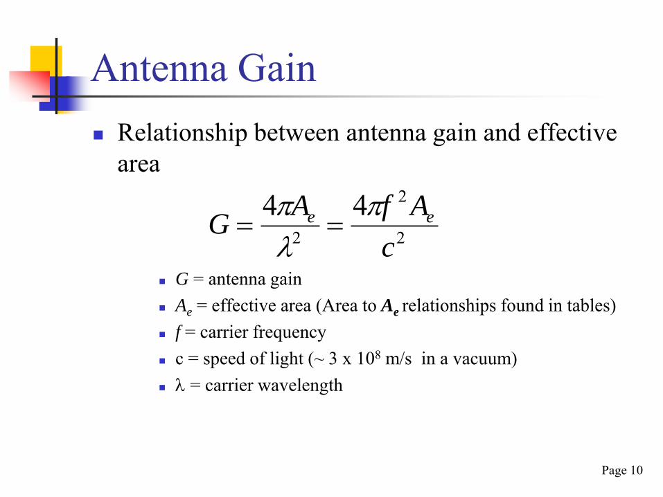
Antenna Gain Relationship between antenna gain and effective
area
G = antenna gain Ae = effective area (Area to Ae relationships found in tables) f = carrier frequency c = speed of light (~ 3 x 10⁸ m/s in a vacuum) = carrier wavelength
Page 10
2
2
2
44c
AfAG ee

Radiated Energy in Free Space
Pr is the power intercepted by the receive antenna aperture Ae which isequal to the power transmitted by the isotropic source Pt times the ratio ofAe / As where As is the area of the entire sphere As = 4pr2
Pr = Pt (Ae / 4pr2) where r is the radius of the sphere or the distancebetween the transmit and receive antennas
Note that the receive power is reduced by the square of the distance –the inverse square law. Also the frequency of the transmitted signal isnot specified since at this point it’s just a matter of relative areas.
Page 11

Propagation Modes Ground-wave propagation Sky-wave propagation Line-of-sight propagation

The Space Radiation Environment
Galactic Cosmic Rays (GCRs)
Solar Protons &
Heavier Ions
Earth’s magnetosphere
Trapped Particles

Radio Waves in the Atmosphere
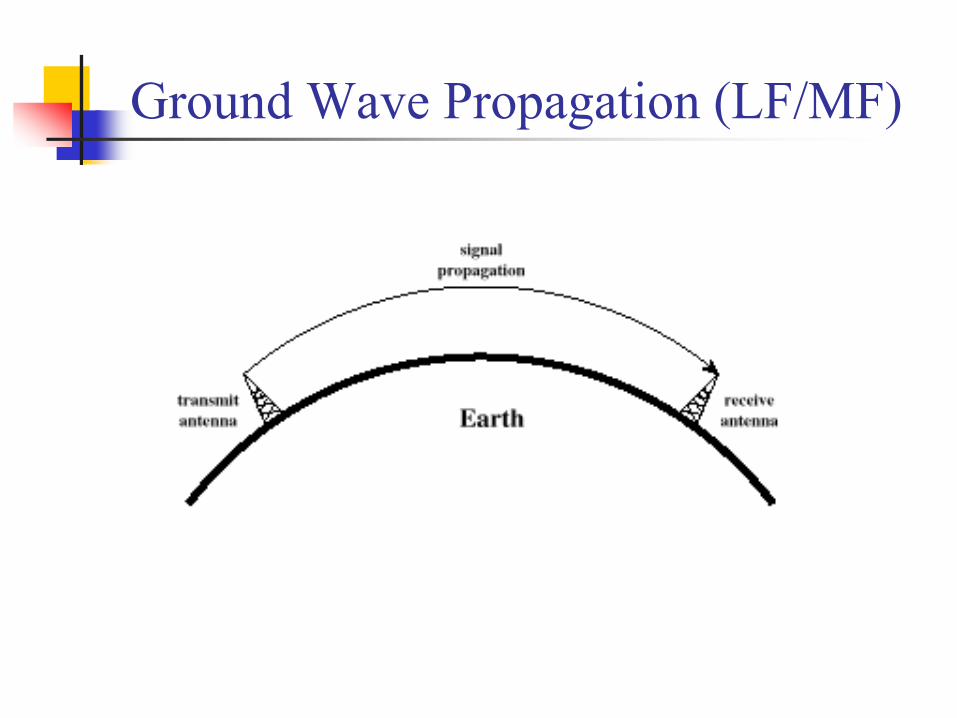
Ground Wave Propagation (LF/MF)

Ground Wave Propagation Follows contour of the earth Can propagate considerable distances Frequencies up to 2 MHz (all frequencies will
have some ground wave/near field) Examples
AM radio (generally) LF and MF Low frequencies which can be effected by
daytime/nighttime
Page 16
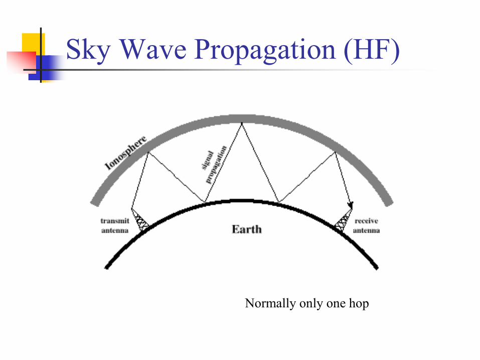
Sky Wave Propagation (HF)
Normally only one hop

Sky Wave Propagation Signal reflected from ionized layer of atmosphere
back down to earth (dependent on sun’s radiation) Signal can travel for a number of hops, back and
forth between ionosphere and earth’s surface; botha short path and a long path (opposite directionaround earth) can also occur
Reflection effect caused by refraction Examples (3 – 30 MHz)
Amateur radio Short-wave radio
Good propagation models based on sunobservations are readily available (MUF)
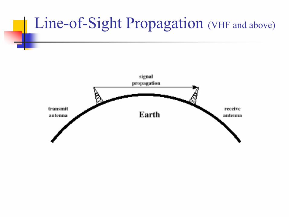
Line-of-Sight Propagation (VHF and above)

Line-of-Sight Propagation Transmitting and receiving antennas must be
within line of sight Satellite communication – signal above 30 – 50 MHz
not normally reflected by ionosphere Ground communication – antennas within effective line
of site due to refraction Refraction – bending of microwaves by the
atmosphere Velocity of electromagnetic wave is a function of the
density of the medium When wave changes medium, speed changes Wave bends at the boundary between mediums
Page 20

Line-of-Sight Equations Optical line of sight
Effective, or radio, line of sight
d = distance between antenna and horizon (km)
h = antenna height (m) K = adjustment factor to account for refraction,
rule of thumb K = 4/3
hd 57.3
hd 57.3

Line-of-Sight Equations Maximum distance between two antennas
for LOS propagation:
h1 = height of antenna one in meters h2 = height of antenna two in meters Note that d is in kilometers (km)
Page 22
2157.3 hh

LOS Wireless Transmission Impairments
Attenuation and attenuation distortion Free space loss Noise Atmospheric absorption Multipath Refraction Thermal noise
Attenuation Strength of signal falls off with distance over
transmission medium (exponential) Attenuation factors for unguided media:
Received signal must have sufficient strength so thatcircuitry in the receiver can interpret the signal (withoutoverloading the front-end of the receiver) – receiversensitivity related to internally generated noise
Signal must maintain a level sufficiently higher thannoise to be received without error
Attenuation is greater at higher frequencies Any attenuation results in signal distortion
Page 24

Free Space Loss Free space loss for an ideal isotropic antenna
Pt = signal power at transmitting antenna Pr = signal power at receiving antenna = carrier wavelength [ c = f ] d = propagation distance between antennas c = speed of light ( ~ 3 x 10⁸ m/s in a vacuum )where d and are in the same units (e.g., meters) and thus f = frequency in Hz
2
2
2
2 44c
fdd
P
P
r
t

Free Space Loss Free space loss equation can be recast:
d
P
PL
r
tdB
4log20log10
dB 98.21log20log20 d
dB 56.147log20log204log20
df
c
fd
using f in Hzand d in meters

Free Space Loss (dB)

Free Space Loss Free space loss accounting for gain of other
antennas
Gt = gain of transmitting antenna Gr = gain of receiving antenna At = effective area of transmitting antenna (aperture) Ar = effective area of receiving antenna d and λ in meters, f in Hz
Page 28
trtrtrr
t
AAf
cd
AA
d
GG
d
P
P2
22
2
224
Not in dB

Free Space Loss Free space loss accounting for gain of other
antennas can be recast as
rtdB AAdL log10log20log20
dB54.169log10log20log20 rt AAdf
Normally don't use these equations since antenna gains are usually given in dB which are just algebraically added to the path loss in dB.
Other Impairments Atmospheric absorption – water vapor and
oxygen contribute to attenuation (microwave)
Multipath – obstacles reflect signals so thatmultiple copies with varying delays arereceived (shadow fading – obstruction ofsignal by objects in the straight-line path)
Refraction – bending of radio waves as theypropagate through the atmosphere
Page 30
Multipath Propagation Reflection - occurs when signal encounters a
surface that is large relative to the wavelength ofthe signal
Diffraction - occurs at the edge of an impenetrablebody that is large compared to the wavelength ofthe radio wave (signals received without a direct line-of-sight)
Scattering – occurs when incoming signal hits anobject whose size in the order of the wavelengthof the signal or less (difficult to predict)
If there isn’t a clear LOS, multipath can be theprimary means of signal reception so it is notalways a negative attribute.

Multipath Propagation
Sketch of Reflection (R), Scattering (S) and Diffraction (D) Propagation Mechanisms in a non-LOS case
Types of Fading Fast fading (usually movement over very short distances)
Slow fading (movement in excess of wavelengths; environment)
Flat fading (or non-selective fading, constant fading over entire signalfrequencies, e.g., path loss)
Selective fading ( e.g., dependent on frequency, unequal over thefrequencies associated the signal)
Rayleigh fading (multiple indirect paths, e.g., no LOS, thusmultipath components dominate, worst-case scenario, can be the dominantfactor in an outdoor environment, special case of Rician distribution.)
Rician fading (direct LOS path and a number of weaker indirectpaths/small-scale fading – multipaths such as found in an indoorenvironment. As the dominant LOS becomes weaker, e.g. fades away,the composite signal degenerates from a Rician distribution to a Rayleighdistribution.

Slow or Small-Scale Fading

Slow or Large-Scale Fading
Base Station
Mobile Station
Consequences of Fading
Error probability is dominated by probability of being in afading low point (dip)
Error probability decreases only linearly with increasing SNR
Fighting the effects of fading becomes mandatory forwireless equipment design
Deterministic modeling of a channel at each point in thepath is very difficult
Statistical modeling of propagation and system behavior -a far more common means of characterization
Empirical determination: On site testing (“Can you hear me now?” )
Page 36

Wireless RF Environment
(slow)
Instantaneous Signal Strength

Effects of Multipath Propagation Multiple copies of a signal may arrive at different
phases If phases add destructively, the signal level relative to
noise declines, making detection more difficult Intersymbol Interference (ISI) (especially digital)
One or more delayed copies of a pulse may arrive at thesame time as the primary pulse for a subsequent bit,e.g., modulation pulses are spread in time into theadjacent symbols. The modulation bandwidth exceeds the coherence bandwidth of the channel.
This is the major obstacle to high speed datatransmission over wireless channels.

Intersymbol Interference (ISI)
Original Transmission
Received
Error Compensation Mechanisms Forward error correction (coding) Adaptive equalization Diversity techniques All three categories are used to combat error
rates in a wireless communications system Good technical reference: Chapter 7 in
Rappaport’s Wireless Communications
textbookPage 40

Forward Error Correction Transmitter adds error-correcting code to data
Code is a function of the data bits Receiver calculates error-correcting code from
incoming data bits If calculated code matches incoming code, no error occurred
If error-correcting codes shows an error, receiver attempts to determine the bits in error and correct.
Requires high levels of data redundancy (2 3 times)
Backward Error Correction: an ACK/NAK protocol like the old AX.25 protocol. When the receiver sends a NAK to the transmitter, it results in a request to retransmit, possibly many times (which means time delays or even a time out/loss of the connection).

Adaptive Equalization (the lemonade maker)
Can be applied to transmissions that carry analog or digitalinformation in a channel with time varying characteristcs. Analog voice or video Digital data, digitized voice or video
Used to combat intersymbol interference (ISI), a majorobstacle, created by multipath within time dispersive channels
Involves ‘restoring’ dispersed symbol energy back into itsoriginal time interval
Techniques Lumped analog circuits Sophisticated digital signal processing algorithms (usually
adaptive, processor based techniques)
Linear Equalization Circuits implemented with DSP

Block Diagram of a Simplified Communications System Using a Receiver Adaptive Equalizer
Diversity Techniques Diversity is based on the fact that individual
channels experience independent fading events Space diversity – techniques involving physical
transmission path (multiple antennas) Frequency diversity – techniques where the signal
is spread out over a larger frequency bandwidth orcarried on multiple frequency carriers (spreadspectrum)
Time diversity – techniques aimed at spreadingthe data out over time (effective on fast fading inconjunction with FEC techniques)
Page 44

Interleaving Data to Spread the Effects of Error Bursts(Time Diversity)
greatly improves error correcting techniques since the number of contiguous errors is reduced
impacting the first three frames of A

A Hobby Gone Amok at K5RG
7-30 MHz Log Periodic in 1985
3 element 40 M Beam & UHF/VHF Log Periodic
Erection of 40 Meter Beam


