

Int. J. Electrochem. Sci., 14 (2019) 5422 – 5434, doi: 10.20964/2019.06.36
International Journal of
ELECTROCHEMICAL SCIENCE
www.electrochemsci.org
Preparation and Electrochemical Properties of Lignin Porous
Carbon Spheres as the Negative Electrode of Lithium Ion
Batteries
Guojun Jiang1, Sheng Xie2*
1 Zhijiang College, Zhejiang University of Technology, Shaoxing, 312000, China 2 College of Material and Textile Engineering, Jiaxing University, Jiaxing, 314000, China *E-mail: [email protected]
Received: 2 February 2019 / Accepted: 26 March 2019 / Published: 10 May 2019
There is a large amount of lignin in the black liquor of papermaking, which can be made into carbon
material and applied to the negative pole of lithium ion battery. It can not only make rational use of
resources, but also reduce environmental pollution. The relationship among pore size, specific surface
area and pore distribution of carbon materials are studied. Porous carbon materials were synthesized by
self-assembly and high-temperature calcination. By constructing porous carbon spheres and changing
the morphology, the anode materials of lithium ion batteries with large specific surface area and high
specific capacity can be obtained. Raman spectrum shows that graphite structures are in porous carbon
spheres. BET results show that porous carbon spheres have a large specific surface area (525.0-867.8
m2/g). The sulfur element in lignosulfonic acid can also improve the performance of the electrode. The
results of constant current charging-discharging show that the specific capacitance of the samples in
the first charge and discharge is 904.3 mAh/g and the unit capacitance of the porous carbon material is
557.9 mAh/g after 50 charging-discharging times when the current density is 1.0 A/g.
Keywords: Lignin, Porous carbon, Sol-gel method, Electrochemical properties
1. INTRODUCTION
Cellulose and lignin are abundant in the plants, but lignin is the second in quantity next to
cellulose [1]. It is a polymer containing benzene rings which can strengthen the cell wall of plants. It
contains a large number of active groups, such as methoxyl, hydroxyl, etc., with great application
value. The structure of lignin is liable to change, so its physical or chemical properties will also be
changed. The specific structure of lignin is not clear at present. Its structure is macromolecular
structure with methoxyl on the benzene ring, which can be represented by C3-C6 [2]. Lignin is
connected with sulfonate groups, such as -SO3Na, to obtain sodium lignin sulfonate, which has a
Int. J. Electrochem. Sci., Vol. 14, 2019
5423
relative molecular weight of 1,000 to 20,000 [3]. The basic component of lignosulfonate is
phenylmethylpropane derivative, which belongs to anionic surfactant. Because lignin sulfonate
contains hydrophilic groups such as sulfonic acid, carboxylic acid and phenolic hydroxyl, it can be
dissolved in various aqueous solutions, which greatly improves the application range of lignin
sulfonate. Lignin sulfonates have a wide range of applications, such as coating particles with lignin
sulfonates, which play a protective role [4]. It can also be used as an abrasion resistant agent for rubber.
Lignin and its derivatives have free radical reactivity [5]. Graft copolymerization can be carried out
with CH3OOCCH=CH2 to prepare a polymer with excellent comprehensive properties [6,7]. In
addition, it can be used as cement water reducer [8], additive [9], dispersant, etc. [10,11], as well as for
preparing oilfield chemicals [12] due to the excellent dispersion performance of lignin sulfonate.
There is a large amount of lignin in the black liquor of papermaking, which can be made into
carbon material and applied to the negative pole of lithium ion battery. According to literatures [13-15],
the electrochemical properties that affect carbon materials include pore size, specific surface area, pore
distribution, etc. By constructing porous carbon spheres and changing the morphology of carbon
materials, the anode materials of lithium ion batteries with large specific surface area and high specific
capacity can be obtained.
The electrochemical properties of lignin carbon spheres as carbon source were studied. Sodium
lignosulfonate microspheres were prepared by ultrasonic chemistry. The effect of ultrasonic treatment
on the particle size of lignin microspheres was studied. Then, the lignin microspheres were carbonized
at high temperature in a tubular furnace to obtain carbon microspheres. Charge and discharge tests and
cyclic voltammetry tests were carried out using carbon spheres as the negative electrode of lithium ion
batteries.
2. EXPERIMENTAL SECTION
2.1 Materials
Sodium lignosulfonate, tween 60, isopropyl alcohol, potassium hydroxide, acetylene black, N-
methylpyrrolidone (NMP) and polyvinylidene fluoride (PVDF) were all analytical reagents purchased
from Shanghai Chemical Reagents Corp (Shanghai, China).
2.2 Preparation of carbon spheres
The flask was fixed on the iron frame and placed in an ultrasonic cleaner. 500 mL isopropyl
alcohol was added to the flask under ultrasound. Then 40 drops of tween 60 were added to the flask.
Dissolve 0.25g sodium lignosulfonate in 20 mL deionized water, and then extract the solution with a
syringe. The sodium lignosulfonate solution was dripped into the flask by microinjection. After
dripping, ultrasound was performed for 1 h. The product is then centrifuged and vacuum dried.
Different shapes and sizes of lignin microspheres were obtained by controlling ultrasonic power. Grind
Int. J. Electrochem. Sci., Vol. 14, 2019
5424
up the products and put into the tube furnace burning (5 ºC/min to 900 ºC and insulation for 1 h under
N2), black lump or powder products were obtained.
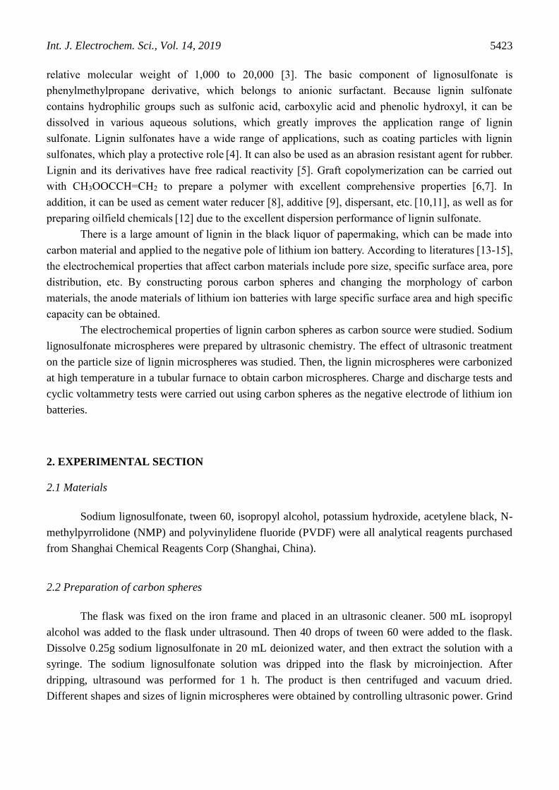
Figure 1. Synthesis mechanism of carbon spheres
The average molecular weight of the lignin sulfonate used in the experiment was 2000.
Different molecular weight lignin sulfonate could self-assemble into molecular spheres with different
sizes in isopropyl alcohol. Tween 60 acts as a dispersant in the solution to disperse lignin microspheres
and reduce the adhesion. After calcining at high temperature, porous carbon materials with certain pore
size and large specific surface area can be obtained. In addition, ultrasound can also affect the particle
size of the microspheres, so that the volume of sodium lignosulfonate microspheres is more uniform.
2.3 Battery assembly
PVDF and NMP were configured as conductive gels at a mass ratio of 1:10. Dissolved under
55 ºC, and stirring until the gel without air bubbles once every 15 min. Then mixed the carbon spheres,
acetylene black and conductive gel according to the proportion of 8:1:1. Adding NMP solvent and
mixing 1 h to form homogeneous slurry. Coating on the copper and drying in the vacuum oven of 60
ºC for 3 h. Dry electrodes with pressing machine, then vacuum drying at 60 ºC by for 24 hours to
prepare electrode materials and assembled into CR 2025 button cell [16].
2.4 Characterization
Fourier infrared spectroscopy (FIRT) was tested by the analyzer (6700, Nicolet) with a
measurement range of 4000 to 400 cm-1 and a resolution of 0.4 cm-1. The samples to be tested were
ground, mixed and laminated with potassium bromide powder, homogeneously. The scanning electron
microscope (S-4700, Hitachi) was used with a working distance of 8 mm and acceleration voltage of
10 kV. A small amount of sample powder is placed on the sample table with conductive adhesive, and
then gold spraying is carried out. The high resolution transmission electron microscopy (JEM-
100CXII, Japanese electronics) was used with a accelerating voltage is 300 kV, and the limit of
resolution of 0.14 nm. Sample powder was dissolved in an appropriate amount of anhydrous ethanol,
and the suspension was obtained after ultrasonic oscillation. Then a small amount of suspension was
Int. J. Electrochem. Sci., Vol. 14, 2019
5425
added to the surface of the copper mesh, and TEM characterization was performed after the solvent
evaporated. Thermogravimetric analyzer (SDT Q600, TA) was used. About 10 mg of sodium
lignosulfonate and composite powder were packed in a small crucible. The whole test process in
nitrogen gas and heated from room temperature to 1000 ºC with 10 ºC/min heating speed. Nitrogen
adsorption test (BET) was using the automatic physical adsorption instrument (ASAP2020, mack
instruments). A small amount of carbon ball powder (0.1 g) vacuumed at 120 ℃, and then tested under
liquid nitrogen. The X-ray photoelectron spectrometer (XPS, KRATOS AXIS Ultra DLD, Shimazu
KRATOS) was used. The light source was AI-KaX rays and the vacuum degree was 3*10-7 Pa. The
laser Raman spectrometer (Lab RAM HR UV800, JOBIN YVON) was used. Excitation light source is
325 nm, 2 times average integration and the scanning range of 200-3000.
After assembled into CR 2025 button battery, the cross-flow charging and discharging
performance of the material was tested. The electrochemical performance parameters such as power
density, energy density and specific capacitance can be obtained by analyzing the results of constant
current charge-discharge test [17].
The calculation formula of specific capacitance is:
𝐶𝑠 =𝐼∆𝑡
𝑚∆𝑉 (1-1)
Where I(A) is the charge and discharge current. Δt for discharge time. m is the mass of the
active material in the electrode material. ΔV is discharge voltage range.
A three-electrode battery system was set up for the cyclic voltammetry test. The material
electrode is the working electrode. Ag/AgCl electrode is the reference electrode. The electrode is the Pt
wafer electrode (1*1 cm2). The electrolyte is 6M KOH solution, and the voltage range is -0.2-0.6v.
3. RESULTS AND DISCUSSION
4000 3500 3000 2500 2000 1500 1000 500
Tra
nsm
itta
nce
(%
)
Wavenumber (cm-1)
3432.7
1650.7
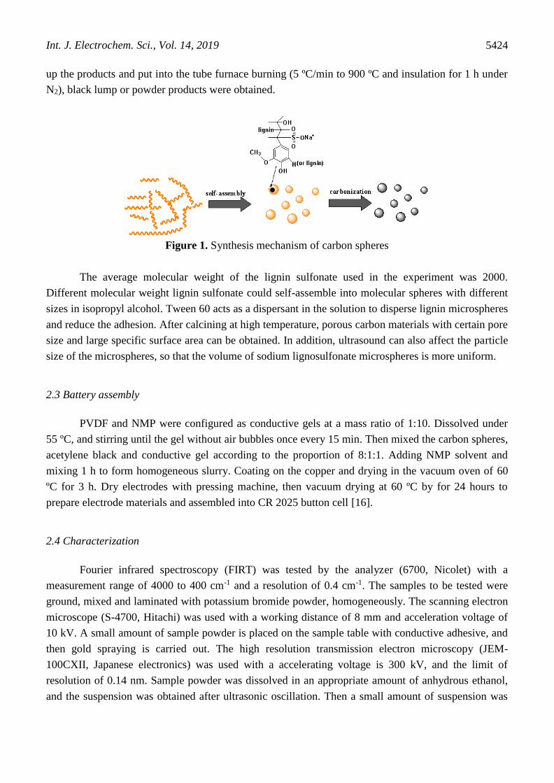
Figure 2. FTIR infrared spectrogram of lignin microspheres
Int. J. Electrochem. Sci., Vol. 14, 2019
5426
In order to understand the chemical structure of lignin microspheres, FTIR tests were carried
out on the lignin microspheres. Figure 1 shows the infrared spectrum of lignin microspheres. The
absorption peak at 3432 cm-1 is wide and strong, indicating that hydroxyl groups are in lignin. Since
the absorption peak of hydroxyl is generally at 3640-2500 cm-1 [18], the amount of phenolic hydroxyl
in lignin directly affects its physical and chemical properties. The absorption peak at 1650 cm-1 is
caused by the vibration of benzene ring C=C, while the wide light band at 1250 cm-1 is the
characteristic absorption peak of sulfonic acid groups. According to the infrared spectrum, the lignin
microspheres contain a large number of active groups, such as sulfonate, hydroxyl, etc.
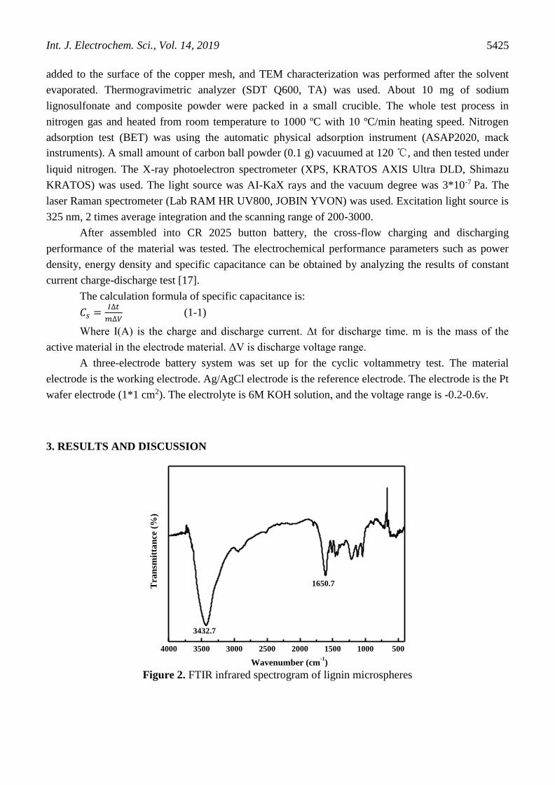
Figure 3. SEM of lignin microspheres and carbon microspheres: a, b and c are the lignin microspheres
under ultrasound, and d is the lignin carbon spheres.
The surface morphology and structure of lignin microspheres were characterized by SEM. As
can be seen from figure 3a, lignin can self-assemble into microspheres in isopropanol solution. Due to
the difference in molecular weight of sodium lignin sulfonate, the size of microspheres formed is also
different. When sodium lignosulfonate was self-assembled under ultrasonic conditions, the size
difference between microspheres was improved according to figure b and c, which is indicated that
ultrasound could reduce the volume difference between microspheres to some extent. After calcined at
high temperature, the lignin microspheres do form porous carbon spheres. It can be seen from the
figure 4 that there are numerous pores in the porous carbon sphere, which greatly increases the specific
Int. J. Electrochem. Sci., Vol. 14, 2019
5427
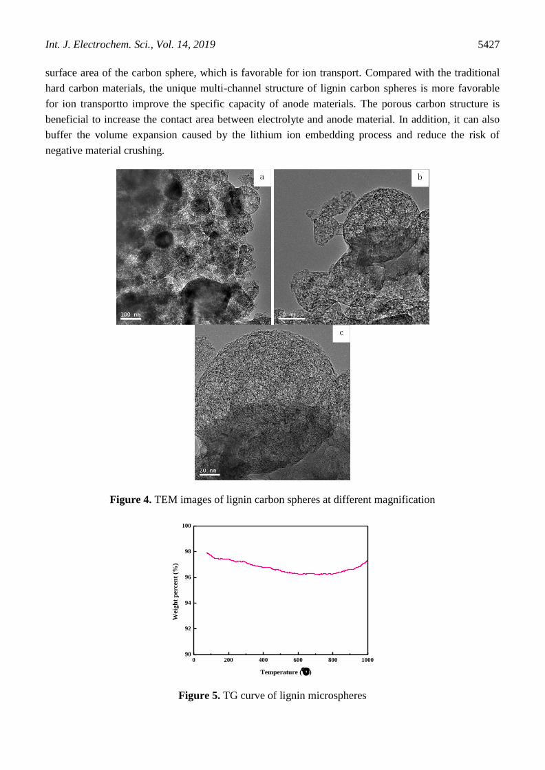
surface area of the carbon sphere, which is favorable for ion transport. Compared with the traditional
hard carbon materials, the unique multi-channel structure of lignin carbon spheres is more favorable
for ion transportto improve the specific capacity of anode materials. The porous carbon structure is
beneficial to increase the contact area between electrolyte and anode material. In addition, it can also
buffer the volume expansion caused by the lithium ion embedding process and reduce the risk of
negative material crushing.
Figure 4. TEM images of lignin carbon spheres at different magnification
0 200 400 600 800 100090
92
94
96
98
100
Wei
gh
t p
erce
nt
(%)
Temperature (℃)
Figure 5. TG curve of lignin microspheres
Int. J. Electrochem. Sci., Vol. 14, 2019
5428
From figure 5, it is indicated that lignin microspheres is mainly small molecules H2O removal
and dispersant below 200 ºC in the process of high temperature calcination. With the temperature
increases, the carbon material gradually graphitized. Because substances with large conjugated systems
are more stable, the other components of the bond that do not participate in the formation of the
delocalized large π will decrease correspondingly [19]. The O and H elements in the lignosulfonate
microsphere flow out the system with N2 and the porous structure is formed. The remaining percentage
is 96.2%. After the formation of the porous structure, the system began to adsorb N2 and the mass
increased.
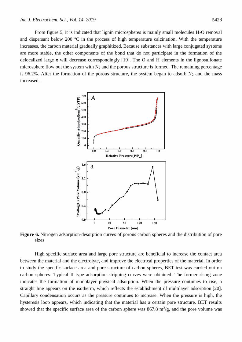
Figure 6. Nitrogen adsorption-desorption curves of porous carbon spheres and the distribution of pore
sizes
High specific surface area and large pore structure are beneficial to increase the contact area
between the material and the electrolyte, and improve the electrical properties of the material. In order
to study the specific surface area and pore structure of carbon spheres, BET test was carried out on
carbon spheres. Typical II type adsorption stripping curves were obtained. The former rising zone
indicates the formation of monolayer physical adsorption. When the pressure continues to rise, a
straight line appears on the isotherm, which reflects the establishment of multilayer adsorption [20].
Capillary condensation occurs as the pressure continues to increase. When the pressure is high, the
hysteresis loop appears, which indicating that the material has a certain pore structure. BET results
showed that the specific surface area of the carbon sphere was 867.8 m2/g, and the pore volume was
Int. J. Electrochem. Sci., Vol. 14, 2019
5429
0.09 cm3/g. It can also be seen from the picture of pore size that the carbon sphere is more
macroporous, which makes the pore volume of the carbon sphere decrease.
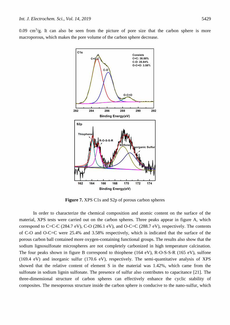
Figure 7. XPS C1s and S2p of porous carbon spheres
In order to characterize the chemical composition and atomic content on the surface of the
material, XPS tests were carried out on the carbon spheres. Three peaks appear in figure A, which
correspond to C=C-C (284.7 eV), C-O (286.1 eV), and O-C=C (288.7 eV), respectively. The contents
of C-O and O-C=C were 25.4% and 3.58% respectively, which is indicated that the surface of the
porous carbon ball contained more oxygen-containing functional groups. The results also show that the
sodium lignosulfonate microspheres are not completely carbonized in high temperature calcination.
The four peaks shown in figure B correspond to thiophene (164 eV), R-O-S-S-R (165 eV), sulfone
(169.4 eV) and inorganic sulfur (170.6 eV), respectively. The semi-quantitative analysis of XPS
showed that the relative content of element S in the material was 1.42%, which came from the
sulfonate in sodium lignin sulfonate. The presence of sulfur also contributes to capacitance [21]. The
three-dimensional structure of carbon spheres can effectively enhance the cyclic stability of
composites. The mesoporous structure inside the carbon sphere is conducive to the nano-sulfur, which
Int. J. Electrochem. Sci., Vol. 14, 2019
5430
plays a role in limiting the capture of active substances and shortening the ion diffusion path, and is
conducive to improving the material multiplier performance.
840 1050 1260 1470 1680 1890
80
100
120
140
160
180
Inte
nsi
ty
Raman Shift (cm-1)
DGI
D/I
G=1.07
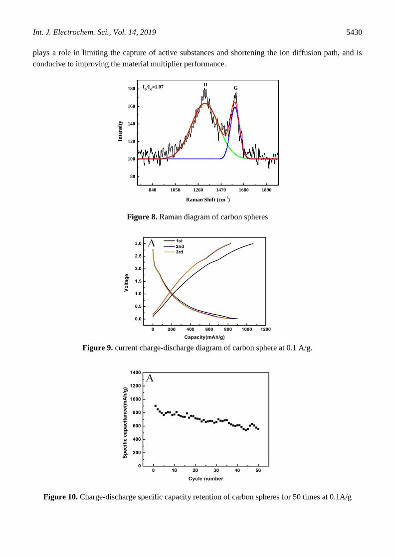
Figure 8. Raman diagram of carbon spheres
Figure 9. current charge-discharge diagram of carbon sphere at 0.1 A/g.
Figure 10. Charge-discharge specific capacity retention of carbon spheres for 50 times at 0.1A/g
Int. J. Electrochem. Sci., Vol. 14, 2019
5431
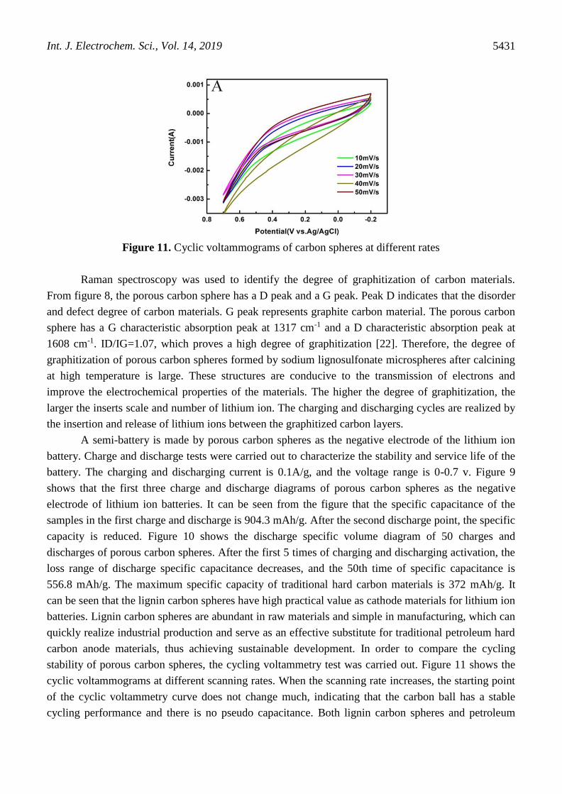
Figure 11. Cyclic voltammograms of carbon spheres at different rates
Raman spectroscopy was used to identify the degree of graphitization of carbon materials.
From figure 8, the porous carbon sphere has a D peak and a G peak. Peak D indicates that the disorder
and defect degree of carbon materials. G peak represents graphite carbon material. The porous carbon
sphere has a G characteristic absorption peak at 1317 cm-1 and a D characteristic absorption peak at
1608 cm-1. ID/IG=1.07, which proves a high degree of graphitization [22]. Therefore, the degree of
graphitization of porous carbon spheres formed by sodium lignosulfonate microspheres after calcining
at high temperature is large. These structures are conducive to the transmission of electrons and
improve the electrochemical properties of the materials. The higher the degree of graphitization, the
larger the inserts scale and number of lithium ion. The charging and discharging cycles are realized by
the insertion and release of lithium ions between the graphitized carbon layers.
A semi-battery is made by porous carbon spheres as the negative electrode of the lithium ion
battery. Charge and discharge tests were carried out to characterize the stability and service life of the
battery. The charging and discharging current is 0.1A/g, and the voltage range is 0-0.7 v. Figure 9
shows that the first three charge and discharge diagrams of porous carbon spheres as the negative
electrode of lithium ion batteries. It can be seen from the figure that the specific capacitance of the
samples in the first charge and discharge is 904.3 mAh/g. After the second discharge point, the specific
capacity is reduced. Figure 10 shows the discharge specific volume diagram of 50 charges and
discharges of porous carbon spheres. After the first 5 times of charging and discharging activation, the
loss range of discharge specific capacitance decreases, and the 50th time of specific capacitance is
556.8 mAh/g. The maximum specific capacity of traditional hard carbon materials is 372 mAh/g. It
can be seen that the lignin carbon spheres have high practical value as cathode materials for lithium ion
batteries. Lignin carbon spheres are abundant in raw materials and simple in manufacturing, which can
quickly realize industrial production and serve as an effective substitute for traditional petroleum hard
carbon anode materials, thus achieving sustainable development. In order to compare the cycling
stability of porous carbon spheres, the cycling voltammetry test was carried out. Figure 11 shows the
cyclic voltammograms at different scanning rates. When the scanning rate increases, the starting point
of the cyclic voltammetry curve does not change much, indicating that the carbon ball has a stable
cycling performance and there is no pseudo capacitance. Both lignin carbon spheres and petroleum
Int. J. Electrochem. Sci., Vol. 14, 2019
5432
hard carbon anode materials have stable electrochemical cycling properties. The preparation and its
stable electrochemical properties lay a solid foundation for its industrial application.
Carbon materials were the first focus in the research of lithium ion batteries, but now people
still pay much attention to carbon materials. Carbon is a kind of material with high crystallinity, large
interplanar spacing and disordered structure. According to the structural characteristics of carbon
materials, it can be divided into two kinds. One is easy to be graphitized, but the other is difficult. The
distance between the hard graphitized carbons is larger. The grain size is smaller, and the grain
orientation is irregular. Macroscopically, hard-graphitized carbon has a porous surface and a small
density. The carbon which is easy to be graphitized mainly includes needle coke, petroleum coke,
carbon microsphere, carbon fiber and so on. The hard graphitized carbon mainly includes organic
polymer pyrolysis carbon (PVC, PVDF, PAN, PVA, etc.), carbon black (acetylene), and resin carbon
(such as polyfurfuryl alcohol PFA-C, epoxy resin, phenolic resin, etc.) [23].
Compared with the carbon material above, the graphite material has the advantages of excellent
conductivity, high crystallinity and obvious lamellar structure. Graphite material with special structure
is more conducive to the insertion and release of lithium ion anode material, so it forms a good
charging and discharging cycle and can provide a higher voltage. Graphite material is a kind of
cathode material with excellent comprehensive performance. Graphite materials can be divided into
two categories, artificial graphite and natural graphite. [24]. Artificial graphite is prepared by high
temperature carbonization of easily graphitized carbon. Artificial graphite mainly consists of
microsphere graphite, graphite fiber and other graphitized carbon. The most concerned is carbon
mesophase microsphere graphite or MCMB for short. MCMB has a highly ordered layered structure
with a spherical shape. MCMB was first developed and manufactured by Osaka Gas Company in
Japan, using as the cathode material for lithium ion batteries. At present, China has developed such
graphite materials. MCMB can be made from petroleum residue or coal tar. After 700 ℃ the MCMB
pyrolysis carbonization, lithium ions embedded quantity can reach about 600 mAh/g, but its
irreversible capacity is higher. As the temperature increased, the degree of graphitization of MCMB
became higher and higher. The reversible capacity also increases gradually, but the irreversible
capacity reduced. In general the graphitized MCMB temperature control around 2800 ℃. So the
reversible capacity can reach about 300 mAh/g, the irreversible capacity will be less than 10%, and the
cycle performance is very good [25]. MCMB materials currently perform well in the application of
cathode materials for lithium ion batteries, but its disadvantage is that it is expensive and its specific
capacity is not high.
Lignosulfonate is the second largest renewable resource after cellulose in nature, and it has the
structure of macromolecule. It can be self-assembled into mesoporous material without template in
solution. Mesoporous carbon (MPCs) material was synthesized by calcining in N2 atmosphere at high
temperature, and its structure was stable, with good electrochemical properties [26]. In consideration
of its hierarchical porosity, the lignin-derived MPC can be the matrix material of supercapacitor that
improves an excellent electron conduction and rate performance. MPCs were synthesized by using the
liginsulfonate, obtained from the pollution of paper industry, as carbon sources,
glutaraldehyde/paraformaldehyde as cross-linking agents and polyvinylpyrrolidone (PVP) as a
dispersing agent. The precursors for MPCs, appeared bister solids, were synthesized by hydrothermal

Int. J. Electrochem. Sci., Vol. 14, 2019
5433
and solvothermal methods. KOH or ZnCl2 were used as pore-enlarging agents. After that, the crude
products were calcinated and charred in a horizontal tube furnace. The as-synthesized MPCs have high
specific surface areas, large pore volumes and narrow pore size distributions and almost porewalls of
the MPCs have been graphitized, which endorse MPCs as leading candidates in application of
electrochemical materials. Additionally, the fabricated capaciters showed a high specific capacitance in
a constant current charge and discharge test and displayed a good retention for more than 1000 cycles
in a cycling test. Furthermore, because of the mesoporous structure that will not limit the ion motion
within the pores, the activated carbon showed a good rate capability. The specific capacity of MPCs
was 360 mAh/g, after 50 charges and discharges. But in our experiment, lignin porous carbon spheres
were used as negative electrode materials, with a charge/discharge ratio of 556.8 mAh/g for 50 times,
which is higher than MCMB and MPCs. It can be widely used to replace the negative electrode
materials used in the current commercial lithium ion batteries. Carbon materials have been the focus of
research in lithium ion batteries for a long time.
4. CONCLUSIONS
Porous carbon materials were prepared by self-assembling lignin and calcining at high
temperature. The results show that the porous carbon spheres contain a large amount of graphite
structure. Porous carbon spheres have a large specific surface area (525.0 -867.8 m2/g). The sulfur in
lignosulfonic acid can also improve the performance of the electrode and it can be used as the cathode
material of lithium ion battery. The results of constant current charging and discharging show that the
unit capacitance is 557.9 mAh/g higher than 372 mAh/g of pure carbon material when the current
density of porous carbon material is 1.0 A/g after 50 times of charging and discharging. Lignin carbon
material can be used as the cathode material of commercial battery.
ACKNOWLEDGEMENTS
We are thankful for the Project Supported by Zhejiang Provincial Natural Science Foundation of China
(LQ18E030013, LQ18E030014), National Natural Science Foundation of China (11702113) and
Scientific Research Project of Zhejiang Provincial Education Department (Y201636479) for the
support to this research.
References
1. C. L. Chio, M. H. Sain and W. S. Qin, Renew. Sust. Energ. Rev., 107 (2019) 232.
2. H. Jiang, T. Sun, C. Li and J. Ma, Rsc Adv., 1 (2011) 954.
3. Dávid Kun and Béla Pukánszky, Eur. Polym. J., 93 (2017) 618.
4. J. T. Duan, E. Litwiller, Seung-Hak Choi and Ingo Pinnau, J. Membrane Sci., 453 (2014) 463.
5. Jun Seok Kim, Y. Y. Lee and Tae Hyun Kim, Bioresource Technol.,236 (2016) 283.
6. P. Alexy, B. Košı́Ková and G. Podstránska. Polymer, 41 (2000) 4901.
7. X. P. Ouyang, L. X. Ke and X. Q. Qiu, J. Disper. Sci. Technol., 30 (2009) 1.
8. M. Zhou, X. Qiu, D. Yang, Fuel Process. Technol., 88 (2007) 375.
Int. J. Electrochem. Sci., Vol. 14, 2019
5434
9. Z. L. Li, Y. X. Pang, H. M. Lou, Bioresources, 4 (2009) 589.
10. S. X. Hu and You-Lo Hsieh, Int. J. Biol. Macromol., 82 (2016) 856.
11. R. D. Mckerracher, A. Holland, A. Cruden and R. G. A. Wills, Carbon, 144 (2019) 333.
12. Z. W. He, J. Yang, Q. F. Lu and Q. Lin, Acs Sustain. Chem. Eng., 1 (2013) 334.
13. H. Lu, A. Cornell, F. Alvarado, M. Behm, S. Leijonmarck, J. B. Li, P. Tomani and G. Lindbergh,
Materials, 9 (2016) 127.
14. T. Chen, Q. Zhang, J. Xu, J. Pan and Y. T. Cheng, Rsc Adv., 6 (2016) 29308.
15. G. F. Xu, Z. J. Shi, Y. H. Zhao, J. Deng and Z. H. Guo, Int. J. Biol. Macromol., 126 (2019) 376.
16. Wang W, Wang H, Wei W, X. Z. Gang and Y. Wang, Chem. Eur. J., 17 (2011) 13461.
17. J. Zhang, Z. H. Huang, R. Lv, Q. H. Yang and F. Y. Kang, Langmuir, 25 (2009) 269.
18. Z. P. Zhao, C. Y. Pan, G. J. Jiang and M. Q. Zhong. Int. J. Electrochem. Sci., 13 (2018) 2945.
19. X. Ma and F. Ouyang, Appl. Surf. Sci., 268 (2013) 566.
20. A. Elmouwahidi, Z. Zapata-Benabithe, F. Carrasco-Marín, F. Carrasco-Marin and C. Moreno-
Castilla, Bioresource Technol., 111 (2012) 185.
21. M. L. Sekirifa, M. Hadj-Mahammed, S. Pallier, L. Baameur, D. Richard and A. H. Ammar, J. Anal.
Appl. Pyrol., 99 (2013) 155.
22. E. W. Zhang and H. L. Zhang, Int. J. Electrochem. Sci., 13 (2018) 12380.
23. C. Wang, V. Murugadoss, J.Kong, Z. F. He and Z. H. Guo, Carbon, 140 (2018) 696.
24. Marcelina Adamska, Urszula Narkiewicz, J. Flourine Chem., 200 (2017) 179.
25. S. B. Li, W. Z. Pan, S. R. Wang, X. Meng, C. R. Jiang and J. T. S. Irvine, Int. J. Hydrogen Energ.,
42 (2017) 16279.
26. F. Chen, W. J. Zhou, H. F. Yao, P. Fan, J. T. Yang, Z. D. Fei and M. Q. Zhong, Green Chem., 15
(2013) 3057.
© 2019 The Authors. Published by ESG (www.electrochemsci.org). This article is an open access
article distributed under the terms and conditions of the Creative Commons Attribution license
(http://creativecommons.org/licenses/by/4.0/).


