

i
PREPARATION, CHARACTERIZATION AND
APPLICATION OF HYBRID POLYMER IN DYE
WASTEWATER TREATMENT
YEAP KIEW LEE
UNIVERSITI SAINS MALAYSIA
2014

ii
PREPARATION, CHARACTERIZATION AND
APPLICATION OF HYBRID POLYMER IN DYE
WASTEWATER TREATMENT
by
YEAP KIEW LEE
Thesis submitted in fulfillment of the requirements
for the degree of
Master of Science
September 2014
iii
ACKNOWLEDGEMENTS
I would like to show my greatest appreciation and gratitude to my supervisor,
Professor Dr. Teng Tjoon Tow, for his professional advice, helpful suggestions,
encouragement, unfailing assistance and guidance throughout the completion of this
study. Without his continuous support, this project would not have been completed.
I would like to thank my co-supervisors, Associate Professor Dr.
Norhashimah Morad and Associate Professor Dr. Poh Beng Teik, who have guided
and inspired me with their helpful knowledge. I am heartily thankful to Associate
Professor Dr. Abbas F.M. Alkarkhi who has offered advice and insight throughout
my work on statistical part. Their willingness to supervise me, improve my study a
lot.
I am grateful to Penfabric Sdn. Bhd. for supplying textile wastewater sample
for the study. Also, I feel thankful to the support of Dr. Lim Jit Kang from the
School of Chemical Engineering for the use of Zetasizer equipment for zeta
potential measurement.
Next, I would like to extend appreciation to all the laboratory assistants
especially to Mdm. Teh Siew Hong, Mr. Ravi Vinayagamuerty, Mdm. Noraida
Bukhari and Mr. Shamsul Zoolkiffli for their cooperation and helpfulness toward the
success of this study.
I am indebted to my dearest friends, Ang Chai Tew, Lee Khai Ern, Ho Yeek
Chia, Low Ling Wei, Tang Soke Kwan, Lim Han Khim, Chou Kian Weng, Tan Kah
Aik, Lim Yee Ling, Chang Pei Xi, Li Zhimin, Claire Su Xin Hui and Chai Chuan
Chun who always assist me when I am facing difficulty in my study. Besides, I
wish to thank Universiti Sains Malaysia for financial support in the form of
postgraduate fellowship and research grant (RU-PRGS).
Last but not least, thanks go out to my family members for being supportive
and their unconditional love which makes my study possible.
Yeap Kiew Lee
2014
iv
TABLE OF CONTENTS
Page
ACKNOWLEDGEMENTS ii
TABLE OF CONTENTS iii
LIST OF TABLES ix
LIST OF FIGURES xiv
LIST OF PLATES xviii
NOMENCLATURES xix
ABSTRAK xxv
ABSTRACT xxvii
CHAPTER ONE: INTRODUCTION
1.1 Overview of Textile Industry 1
1.2 Wastewater Treatment Methods 3
1.3 Hybrid Polymers in Coagulation-flocculation 5
1.4 Problem Statement 6
1.5 Objectives 8
1.6 Scope of the Study 8
CHAPTER TWO: LITERATURE REVIEW
2.1 Textile Dyes 10
2.1.1 Textile Fibres 10
2.1.1.1 Natural Fibre 11
2.1.1.2 Synthetic / Man-made Fibre 11
2.1.2 Classification of Dye 12
v
2.2 Treatment of Dye Wastewater 13
2.3 Coagulation-flocculation 16
2.3.1 Mechanisms of Coagulation-flocculation 22
2.3.1.1 Charge Neutralization 23
2.3.1.2 Electrostatic Patch 24
2.3.1.3 Bridging 26
2.3.2 Factors Affecting Coagulation-flocculation 30
2.3.2.1 Initial pH 30
2.3.2.2 Flocculant Dosage 32
2.3.2.3 Stirring Speed and Time 33
2.4 Coagulation Reagents 35
2.4.1 Hydrolyzing Metallic Salts 35
2.4.2 Pre-hydrolyzing Metallic Salts 37
2.4.3 New Generation Coagulants 39
2.5 Hybrid Polymers 39
2.5.1 Types of Hybrid Polymers 40
2.5.2 Characterization of Hybrid Polymers 41
2.5.2.1 Chemical Properties
(a) Fourier Transform Infrared (FT-IR) Spectroscopy
42
42
2.5.2.2 Physical Properties
(a) Intrinsic Viscosity
(b) Conductivity
(c) Zeta Potential ()
43
43
45
46
2.5.2.3 Morphological Properties 47

vi
(a) Transmission Electron Microscopy (TEM)
(b) Scanning Electron Microscopy (SEM)
(c) Energy Dispersive X-Ray Spectroscopy (EDS)
47
48
49
2.6 Statistical Design of Experiment 50
2.6.1 Two Level Factorial Design 51
2.6.2 Response Surface Methodology (RSM) 52
2.6.2.1 Box-Behnken Design (BBD) 52
2.6.2.2 Central Composite Design (CCD) 53
CHAPTER THREE: METHODOLOGY
3.1 Materials and Chemicals 55
3.2 Equipments and Instruments 56
3.3 Overview of the Study 57
3.4 Preparation of PAMIPCl Copolymers 59
3.5 Preparation of PACl-PAMIPCl Hybrid Polymers 69
3.6 Characterization of PAMIPCl and PACl-PAMIPCl Hybrid Polymers 60
3.6.1 Chemical Properties 61
3.6.1.1 Fourier Transform Infrared (FT-IR) Spectroscopy 61
3.6.2 Physical Properties 61
3.6.2.1 Solution Conductivity 61
3.6.2.2 Solution Viscosity 61
3.6.2.3 Solution Intrinsic Viscosity 62
3.6.3 Morphological Properties 63
3.6.3.1 Scanning Electron Microscopy-Energy Dispersive X- 63
vii
ray Spectroscopy (SEM-EDS)
3.7 Coagulation-flocculation Study in Dye Wastewater Treatment 63
3.7.1 Experimental Design for Application of PACl-PAMIPCl
Hybrid Polymer in Synthetic Reactive Cibacron Blue F3GA
(RCB) and Disperse Terasil Yellow W-4G (DTY) Dyes
64
3.7.1.1 Screening of Factors 64
3.7.1.2 Optimization of Synthetic Dye Wastewater Treatment 65
3.7.2 Experimental Design for Application of PACl-PAMIPCl
Hybrid Polymer in Industrial Textile Wastewater Treatment
66
3.7.2.1 Screening of Factors 66
3.7.2.2 Optimization of Industrial Textile Wastewater
Treatment
67
3.8 Statistical Analysis 67
CHAPTER FOUR: RESULTS AND DISCUSSION
4.1 Preparation of PAMIPCl Copolymers 68
4.2 Characterization of PAMIPCl Copolymers 69
4.2.1 Chemical Properties 69
4.2.1.1 Fourier Transform Infrared (FT-IR) Spectroscopy 69
4.2.2 Physical Properties 72
4.2.2.1 Solution Conductivity 72
4.2.2.2 Solution Viscosity 72
4.2.2.3 Intrinsic Viscosity 73
4.3 Preparation of PACl-PAMIPCl Hybrid Polymers 74
viii
4.4 Characterization of PACl-PAMIPCl Hybrid Polymers 75
4.4.1 Chemical Properties 75
4.4.1.1 Fourier Transform Infrared (FT-IR) Spectroscopy 75
4.4.2 Physical Properties 78
4.4.2.1 Solution Conductivity 78
4.4.2.2 Solution Viscosity 78
4.4.2.3 Intrinsic Viscosity 79
4.4.3 Morphological Properties 80
4.4.3.1 Scanning Electron Microscopy (SEM) 80
4.4.3.2 Energy Dispersive X-ray Spectroscopy (EDS) 82
4.5 Application of PACl-PAMIPCl Hybrid Polymers in Synthetic Dye
Wastewater Treatment
83
4.5.1 Characteristic of Synthetic Dye Wastewater 84
4.5.2 Effect of the Composition of PACl-PAMIPCl Hybrid
Polymers in Dye/ Color Removal
85
4.5.3 Mechanism of Dye/ Color Removal Using PACl-PAMIPCl
Hybrid Polymers
87
4.5.3.1 Variation of pH and Zeta Potential ( ) 87
4.5.3.2 Chemical Functional Groups of Sludge 93
4.5.3.3 Surface Morphology of Sludge 94
4.5.4 Screening of Variables for Dye Wastewater Treatment 97
4.5.4.1 Reactive Cibacron Blue F3GA (RCB) Dye 97
4.5.4.2 Disperse Terasil Yellow W-4G (DTY) Dye 101
4.5.5 Optimization of Variables for Dye Wastewater Treatment 105
ix
4.5.5.1 Reactive Cibacron Blue F3GA (RCB) Dye 105
4.5.5.2 Disperse Terasil Yellow W-4G (DTY) Dye 114
4.6 Application of PACl-PAMIPCl Hybrid Polymers in Industrial
Textile Wastewater Treatment
124
4.6.1 Characteristics of Industrial Textile Wastewater 124
4.6.2 Screening of Variables for Dye Wastewater Treatment 124
4.6.3 Optimization of Variables for Dye Wastewater Treatment 129
4.7 Comparison of PACl-PAMIPCl Hybrid Polymers with Other
Inorganic-organic Hybrid Polymers in Dye Wastewater Treatment
139
CHAPTER FIVE: CONCLUSIONS AND RECOMMENDATION
FOR FUTURE RESEARCH
5.1 Conclusions
5.2 Recommendation for Future Research
140
142
REFERENCES 143
APPENDICES 164
LIST OF PUBLICATION 212
x
LIST OF TABLES
Page
2.1 Characteristics of dyes used in textile industry. 14
2.2 Advantages and disadvantages of different methods of dye removal
from textile wastewater.
17
3.1 Materials and chemicals. 55
3.2 Equipments and instruments. 56
3.3 Experimental range and level of factors used in 25-1
one-half
fractional factorial design for synthetic dye wastewaters using PACl-
PAMIPCl hybrid polymer.
65
3.4 Experimental range and level of factors used in FCCD for synthetic
dye wastewaters treatment using PACl-PAMIPCl hybrid polymer.
65
3.5 Levels of factors used in 24 full factorial design for industrial textile
wastewater treatment using PACl-PAMIPCl hybrid polymer.
66
3.6 Levels of factors used in FCCD for industrial textile wastewater
treatment using PACl-PAMIPCl hybrid polymer.
67
4.1 Observed FT-IR wavenumbers, corresponding functional group and
remarks for AM, PAM and PAMIPCl copolymers.
71
4.2 Observed FT-IR wavenumbers, corresponding functional group and
remarks for PACl and PACl-PAMIPCl hybrid polymers .
77
4.3 Characteristics of RCB and DTY dyes. 84
4.4 The 25-1
factional factorial design matrix for RCB dye wastewater
treatment using PACl-PAMIPCl hybrid polymer.
98
4.5 ANOVA analysis for color removal using PACl-PAMIPCl hybrid 101
xi
polymer in RCB dye wastewater.
4.6 ANOVA analysis for COD reduction using PACl-PAMIPCl hybrid
polymer in RCB dye wastewater.
101
4.7 The 25-1
factional factorial design matrix for DTY dye wastewater
treatment using PACl-PAMIPCl hybrid polymer.
102
4.8 ANOVA analysis for color removal using PACl-PAMIPCl hybrid
polymer in DTY dye wastewater.
104
4.9 ANOVA analysis for COD reduction using PACl-PAMIPCl hybrid
polymer in DTY dye wastewater.
105
4.10 The FCCD results for color removal and COD reduction efficiencies
by using PACl-PAMIPCl hybrid polymer in RCB dye wastewater.
106
4.11 Estimated regression coefficients for color removal and COD
reduction efficiencies by using PACl-PAMIPCl hybrid polymer in
RCB dye wastewater.
108
4.12 ANOVA for color removal efficiency by using PACl-PAMIPCl
hybrid polymer in RCB dye wastewater.
110
4.13 ANOVA for COD reduction efficiency by using PACl-PAMIPCl
hybrid polymer in RCB dye wastewater.
110
4.14 Confirmation tests of the optimum color removal and COD reduction
of RCB dye wastewater using PACl-PAMIPCl hybrid polymer.
114
4.15 The FCCD results for color removal and COD reduction efficiencies
by using PACl-PAMIPCl hybrid polymer in DTY dye wastewater.
115
4.16 Estimated regression coefficients for color removal and COD
reduction efficiencies by using PACl-PAMIPCl hybrid polymer in
117
xii
DTY dye wastewater.
4.17 ANOVA for color removal efficiency by using PACl-PAMIPCl
hybrid polymer in DTY dye wastewater.
119
4.18 ANOVA for COD reduction efficiency by using PACl-PAMIPCl
hybrid polymer in DTY dye wastewater.
119
4.19 Confirmation tests of the optimum color removal and COD reduction
of DTY dye wastewater using PACl-PAMIPCl hybrid polymer.
123
4.20 Characteristics of industrial textile wastewater. 124
4.21 The 24-1
factional factorial design matrix for industrial textile
wastewater treatment using PACl-PAMIPCl hybrid polymer.
125
4.22 ANOVA analysis for color removal using PACl-PAMIPCl hybrid
polymer in industrial textile wastewater.
127
4.23 ANOVA analysis for COD reduction using PACl-PAMIPCl hybrid
polymer in industrial textile wastewater.
127
4.24 The FCCD results for color removal and COD reduction efficiencies
by using PACl-PAMIPCl hybrid polymer in industrial textile
wastewater.
128
4.25 Estimated regression coefficients for color removal and COD
reduction efficiencies by using PACl-PAMIPCl hybrid polymer in
industrial textile wastewater.
130
4.26 ANOVA for color removal efficiency by using PACl-PAMIPCl
hybrid polymer in industrial textile wastewater.
131
4.27 ANOVA for COD reduction efficiency by using PACl-PAMIPCl
hybrid polymer in industrial textile wastewater.
131
xiii
4.28 Confirmation tests of the optimum color removal and COD reduction
of industrial textile wastewater using PACl-PAMIPCl hybrid
polymer.
135
4.29 Comparison of PACl-PAMIPCl hybrid polymers with other
inorganic-organic hybrid polymers in dye wastewater treatment.
136
A1.1 Acceptable conditions for discharge of industrial effluent or mixed
effluent of standards A and B.
161
A1.2 Acceptable conditions for discharge of industrial effluent containing
chemical oxygen demand (COD) for specific trade or industry
sector.
162
A2 Coagulation-flocculation performances of different hybrid polymers
in wastewater treatment.
163
A3 Effect of EPI to AM molar ratio on PAMIPCl copolymers
conversion.
186
A4 Conductivity of PAMIPCl copolymers in different concentrations. 186
A5 Viscosity of PAMIPCl copolymers at different ratio of EPI to AM. 187
A6 Viscosity of PAMIPCl copolymers at different concentrations. 188
A7 Reduced viscosity of PAMIPCl copolymers at different
concentrations.
192
A8 Conductivity of PACl-PAMIPCl hybrid polymers at different
concentrations.
196
A9 Viscosity of PACl-PAMIPCl hybrid polymers at different
concentrations.
197
A10 Reduced viscosity of PACl-PAMIPCl hybrid polymers at different 201
xiv
concentrations.
A11.1 Effect of different ratio of PACl-PAMIPCl hybrid polymers at
different pH in color removal from RCB dye wastewater.
205
A11.2 Effect of different ratio of PACl-PAMIPCl hybrid polymers at
different pH in color removal from DTY dye wastewater.
206
A12.1 The color removal efficiency, variation of pH and in treating RCB
dye wastewater.
207
A12.2 The color removal efficiency, variation of pH and in treating DTY
dye wastewater.
208
xv
LIST OF FIGURES
Page
3.1 An overview of the methodology. 58
4.1 PAMIPCl copolymers conversion (%) versus EPI to AM molar ratio
(%).
69
4.2 FT-IR spectra for AM, PAM and PAMIPCl copolymers. 70
4.3 Conductivity of PAMIPCl copolymers in different concentrations. 72
4.4 Solution viscosity of PAMIPCl copolymers at different ratio of
epichlorohydrin (%).
73
4.5 Reduced viscosity of PAMIPCl copolymers at different concentrations. 74
4.6 Preparation of (a) PAMIPCl composite copolymer; (b) PACl-PAMIPCl
hybrid polymer.
75
4.7 FT-IR spectra for PAMIPCl b, PACl-PAMIPCl hybrid polymers and
PACl.
76
4.8 Conductivity of PACl-PAMIPCl hybrid polymers in different
concentrations.
78
4.9 Solution viscosity of PACl-PAMIPCl hybrid polymers at different ratio
of PACl (%).
79
4.10 Reduced viscosity of PACl-PAMIPCl hybrid polymers at different
concentrations.
80
4.11 Effect of different ratios of PACl-PAMIPCl hybrid polymer at different
pH in color removal from RBC dye wastewater.
86
4.12 Effect of different ratios of PACl-PAMIPCl hybrid polymer at different
pH in color removal from DTY dye wastewater.
87
xvi
4.13 in treating RCB
dye wastewater.
90
4.14 in treating DTY
dye wastewater.
92
4.15 Chemical structure of sludge formed in treating RCB dye wastewater. 93
4.16 Chemical structure of sludge formed in treating DTY dye wastewater. 94
4.17 Normal probability plot of standardized effect for RCB dye color
removal (%) using PACl-PAMIPCl hybrid polymer.
100
4.18 Normal probability plot of standardized effect for RCB dye COD
reduction (%) using PACl-PAMIPCl hybrid polymer.
100
4.19 Normal probability plot of standardized effect for DTY dye color
removal (%) using PACl-PAMIPCl hybrid polymer.
103
4.20 Normal probability plot of standardized effect for DTY dye COD
reduction (%) using PACl-PAMIPCl hybrid polymer.
104
4.21 Normal probability plot for synthetic RCB dye wastewater in color
removal.
111
4.22 Normal probability plot for synthetic RCB dye wastewater in COD
reduction.
111
4.23 The three dimensional surface plots for RCB dye color removal as a
function of: (i) initial concentration and dosage; (ii) initial
concentration and agitation speed; (iii) initial pH and dosage; (iv)
agitation speed and agitation time at an intermediate setting of initial
concentration 200 mg/L, initial pH 7.5, dosage 20 mg/L, agitation
speed 200 rpm and agitation time 9 min.
112
xvii
4.24 The three dimensional surface plots for RCB dye COD reduction as a
function of: (i) initial concentration and dosage; (ii) initial
concentration and agitation speed; (iii) initial pH and dosage; (iv)
agitation speed and agitation time at an intermediate setting of initial
concentration 200 mg/L, initial pH 7.5, dosage 20 mg/L, agitation
speed 200 rpm and agitation time 9 min.
113
4.25 Normal probability plot for synthetic DTY dye wastewater in color
removal.
120
4.26 Normal probability plot for synthetic DTY dye wastewater in COD
reduction.
120
4.27 The three dimensional surface plots for DTY dye color removal as a
function of: (i) initial concentration and dosage; (ii) initial pH and
dosage; (iii) initial concentration and agitation speed; (iv) agitation
speed and agitation time at an intermediate setting of initial
concentration 200 mg/L, initial pH 7.5, dosage 20 mg/L, agitation
speed 200 rpm and agitation time 9 min.
121
4.28 The three dimensional surface plots for DTY dye COD reduction as a
function of: (i) initial concentration and dosage; (ii) initial pH and
dosage; (iii) initial concentration and agitation speed; (iv) agitation
speed and agitation time at an intermediate setting of initial
concentration 200 mg/L, initial pH 7.5, dosage 20 mg/L, agitation
speed 200 rpm and agitation time 9 min.
122
4.29 Normal probability plot of standardized effect for industrial textile
wasteater color removal (%) using PACl-PAMIPCl hybrid polymer.
126
xviii
4.30 Normal probability plot of standardized effect for industrial textile
wasteater COD reduction (%) using PACl-PAMIPCl hybrid polymer.
126
4.31 Normal probability plot for industrial textile wastewater in color
removal.
132
4.32 Normal probability plot for industrial textile wastewater in COD
reduction.
132
4.33 The three dimensional surface plots for industrial textile wastewater
color removal as a function of: (i) initial pH and agitation speed; (ii)
initial pH and agitation time; (iii) agitation speed and agitation time at
an intermediate setting of initial pH 7.5, dosage 25 mg/L, agitation
speed 200 rpm and agitation time 9 min.
133
4.34 The three dimensional surface plots for industrial textile wastewater
COD reduction as a function of: (i) initial pH and agitation speed; (ii)
initial pH and agitation time; (iii) dosage and agitation speed; (iv)
agitation speed and agitation time at an intermediate setting of initial
pH 7.5, dosage 25 mg/L, agitation speed 200 rpm and agitation time 9
min.
134
xix
LIST OF PLATES
Page
4.1 SEM image of PAMIPCl.b copolymer (4% EPI : 96% AM) under
magnification power 50x.
81
4.2 SEM image of PACl-PAMIPCl 1 hybrid polymer (90% PACl : 10%
PAMIPCl) under magnification power 50x.
82
4.3 EDS of PAMIPCl.b copolymer (4% EPI : 96% AM). 83
4.4 EDS of PACl-PAMIPCl 1 hybrid polymer (90% PACl : 10%
PAMIPCl).
83
4.5 Surface morphology of sludge using PACl in treating RCB dye
wastewater under magnification power 1,000x.
95
4.6 Surface morphology of sludge using PACl-PAMIPCl hybrid polymer
in treating RCB dye wastewater under magnification power 1,000x.
96
4.7 Surface morphology of sludge using PACl in treating DTY dye
wastewater under magnification power 1,000x.
96
4.8 Surface morphology of sludge using PACl-PAMIPCl hybrid polymer
in treating DTY dye wastewater under magnification power 1,000x.
97
4.9 Comparison of RCB dye wastewater before (left side) and after (right
side) treatment.
114
4.10 Comparison of DTY dye wastewater before (left side) and after (right
side) treatment.
123
4.11 Comparison of industrial textile wastewater before (left side) and after
(right side) treatment.
135
xx
NOMENCLATURES
PART 1
c Concentration of polymer
e Electronic charge
i Ionic strength
k Number of variable
k* Constant
n Avogadro’s number
η Viscosity
ηi Viscosity of the polymer
ηo Viscosity of the water
ηsp Specific viscosity
ηsp/c Reduced viscosity
[η] Intrinsic viscosity
ρ Density of the solution
t Measured flow time
wp Organic content
PART 2
A Calibration constant of the viscometer
B Basicity
β0 Offset term
βi Linear effect
βii Squared effect
xxi
βij Interaction effect
Cf Final values of color point (Pt-Co) and COD of supernatant
(mg/L)
Ci Initial values of color point (Pt-Co) and COD of supernatant
(mg/L)
C0 Number of center point
Error
Electrical permittivity of the solvent
1/K Double layer thickness
Mw Molecular weight
N Number of experimental point
θ Surface coverage
R2 Determination coefficient
R2adj Adjusted determination coefficient
T Absolute temperature
W Overall stability ratio
Wf Weight of filter paper with sludge
Wi Weight of filter paper
X Factor
Y Response
Zeta potential
PART 3
Al(OH)3 Aluminium hydroxide
xxii
AlCl3 Aluminium chloride
FeCl3 Ferric chloride
Fe(OH)3 Ferric hydroxide
FeSO4 Ferric sulphate
MgCl2 Magnesium chloride
Mg(OH)2 Magnesium hydroxide
NaHSO3 Sodium bisulphite
(NH4)2S2O8 Ammonium persulphate
TiCl4 Titanium tetrachloride
PART 4
AM Acrylamide
ANOVA Analysis of variance
AS-Ee Aluminium sulphate-Enteromorpha extract
BBD Box behnken design
BOD Biochemical oxygen demand
CAC1 First critical associating concentration
CAC2 Second critical associating concentration
CBF-PACl Compound bioflocculant- polyaluminium chloride
CCD Central Composite Design
CMC-PAM Carboxymethyl chitosan-graft-polyacrylamide
COD Chemical oxygen demand
CSAX Crosslinked starch-graft-polyacrylamide-co-sodium xanthate
DO Dissolved oxygen
xxiii
DTY Disperse terasil yellow W-4G
Ep Enteromorpha polysaccharides
EPI Epichlorohydrin
EDS Energy-dispersive x-ray spectroscopy
FCCD Face-centered central composite design
FT-IR Fourier transform infrared spectroscopy
HPMC-PAM Hydroxypropyl methyl cellulose-grafted-polyacrylamide
IEP Iso-electric point
IPC Inorganic polymeric coagulant
k-cgn-HMAAm k-carrageenan-graft-N-(hydroxymethyl) acrylamide
KGM-PAM-SX Konjac glucomannan-graft-polyacrylamide-co-sodium
xanthate
OPC Organic polymeric coagulant
ORP Oxidation reduction potential
PAA Poly(acrylic acid)
P(AA-AM) Poly(acrylamide-co-acrylic acid)
P(AM-AA-AMPS) Poly(acrylamide-co-acrylic acid-2-acrylamido-2-methyl-1-
propanesulfonic acid)
PACl Polyaluminium chloride
PACl-CBF Polyaluminium chloride-compound bioflocculant
PACl-chitosan Polyaluminium chloride-chitosan
PACl-EPI-DMA Polyaluminium chloride-epichlorohydrin dimethylamine
PACl-PAMIPCl Polyaluminium chloride-poly(3-acrylamido-isopropanol
chloride)
xxiv
PACl-PDMDAACl Polyaluminium chloride- polydiallydimethylammonium
chloride
PACS Polyaluminium chloro-sulphate
PAFCl Polyaluminium-ferric chloride
PAFS Polyaluminium-ferric-sulphate
PAFSiCl Polyaluminium-ferric-silicate-chloride
PAS Polyaluminium-sulphate
PASiCl Polyaluminium-silicate-chloride
PAM Polyacrylamide
PAMIPCl Poly(3-acrylamido-isopropanol chloride)
PDA Photometric dispersion analyzer
PDMDAACl Polydiallydimethylammonium chloride
PDMDAACl-PAM Polydiallydimethylammonium chloride-polyacrylamide
(PEG)xLiClO4 Poly(ethylene) glycol-lithium perchlorate salt
PEO Poly(ethylene oxide)
PFACl-PDMDAACl Polyferric aluminium chloride-polydimethyldiallylammonium
chloride
PFASiS Polyferric-aluminium-silicate-sulphate
PFCl Polyferric chloride
PFCl-EPI-DMA Polyferric chloride-epichlorohydrin-dimethylamine
PFCl-PDMDAACl Polyferric chloride- polydimethyldiallylammonium
chloride
PFCl-LA Polyferric chloride lignin-acrylamide polymer
PFMS Polyferric-magnesium-sulphate
PFSiS Polyferric-silicate-sulphate

xxv
PFS Polyferric sulphate
PFS-PAM Polyferric sulphate-polyacrylamide
Pt-Co Platinum-Cobalt scale
PZSS Polyzinc-silicate-sulphate
RCB Reactive cibacron blue F3GA
RSM Response surface methodology
SCPAMPAA 3-chloro-2-hydroxypropyl trimethylammonium chloride
modified starch-graft-poly(acrylamide-co-acrylic acid)
SEM Scanning electron microscopy
TEM Transmission electron microscope
TDS Total dissolved solid
TOC Total organic carbon

xxvi
PENYEDIAAN, PENCIRIAN DAN PENGGUNAAN POLIMER HIBRID
DALAM RAWATAN AIR SISA PEWARNA
ABSTRAK
Polimer hibrid organik-bukan organik, polyaluminium klorida-poli (3-
acrylamido-isopropanol klorida) (PACl-PAMIPCl) disediakan, dicirikan dan
digunakan untuk pengolahan air sisa pewarna Reaktif Cibacron Biru F3GA (RCB),
Dispersi Terasil Kuning W-4G (DTY) dan industri tekstil. Copolimer PAMIPCl
telah disediakan dengan mengubah nisbah molar epichlorohydrin (EPI) dengan
acrylamide (AM). Hasil maksimum PAMIPCl adalah 98.12% dengan kelikatan
tertinggi 23.65 cP apabila nisbah molar EPI kepada AM mencapai 4% : 96%.
Polimer hibrid PACl-PAMIPCl telah disediakan melalui pengadunan fizikal
PAMIPCl dengan PACl. Pengimbasan mikroskop elektron (SEM) telah dijalankan
berasingan untuk menjelaskan mikrostruktur polimer hibrid dalam bentuk akueus
dan pepejal. 90% PACl : 10% PAMIPCl merupakan nisbah terbaik dalam
pengolahan air sisa pewarna simulasi: 95.00 dan 100.00% pemecatan warna untuk
pewarna RCB dan DTY masing-masing. Kajian potensi zeta menunjukkan bahawa
peneutralan caj dan penjerapan-penyambung berlaku dalam mekanisme
pemberbukuan untuk pengolahan pewarna RCB dan DTY masing-masing.
Morfologi permukaan enapcemar dibentuk dengan menggunakan polimer hibrid
PACl-PAMIPCl bagi air sisa pewarna RCB dan DTY didapati lebih padat secara
relatif, agregat dan licin daripada menggunakan PACl. Kaedah gerak balas
permukaan (RSM) digunakan untuk menyiasat faktor bebas yang menjejas
penyingkiran warna dan penurunan COD dalam air sisa pewarna RCB dan DTY.
xxvii
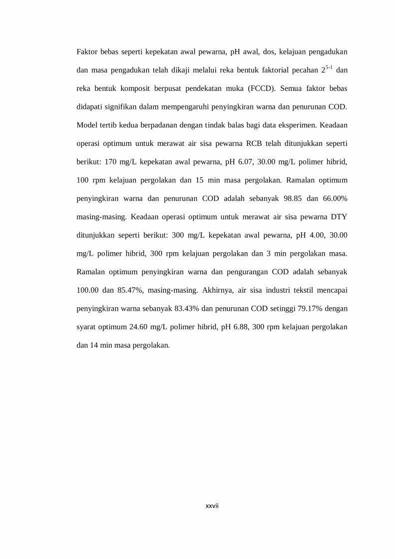
Faktor bebas seperti kepekatan awal pewarna, pH awal, dos, kelajuan pengadukan
dan masa pengadukan telah dikaji melalui reka bentuk faktorial pecahan 25-1
dan
reka bentuk komposit berpusat pendekatan muka (FCCD). Semua faktor bebas
didapati signifikan dalam mempengaruhi penyingkiran warna dan penurunan COD.
Model tertib kedua berpadanan dengan tindak balas bagi data eksperimen. Keadaan
operasi optimum untuk merawat air sisa pewarna RCB telah ditunjukkan seperti
berikut: 170 mg/L kepekatan awal pewarna, pH 6.07, 30.00 mg/L polimer hibrid,
100 rpm kelajuan pergolakan dan 15 min masa pergolakan. Ramalan optimum
penyingkiran warna dan penurunan COD adalah sebanyak 98.85 dan 66.00%
masing-masing. Keadaan operasi optimum untuk merawat air sisa pewarna DTY
ditunjukkan seperti berikut: 300 mg/L kepekatan awal pewarna, pH 4.00, 30.00
mg/L polimer hibrid, 300 rpm kelajuan pergolakan dan 3 min pergolakan masa.
Ramalan optimum penyingkiran warna dan pengurangan COD adalah sebanyak
100.00 dan 85.47%, masing-masing. Akhirnya, air sisa industri tekstil mencapai
penyingkiran warna sebanyak 83.43% dan penurunan COD setinggi 79.17% dengan
syarat optimum 24.60 mg/L polimer hibrid, pH 6.88, 300 rpm kelajuan pergolakan
dan 14 min masa pergolakan.
xxviii
PREPARATION, CHARACTERIZATION AND APPLICATION OF
HYBRID POLYMER IN DYE WASTEWATER TREATMENT
ABSTRACT
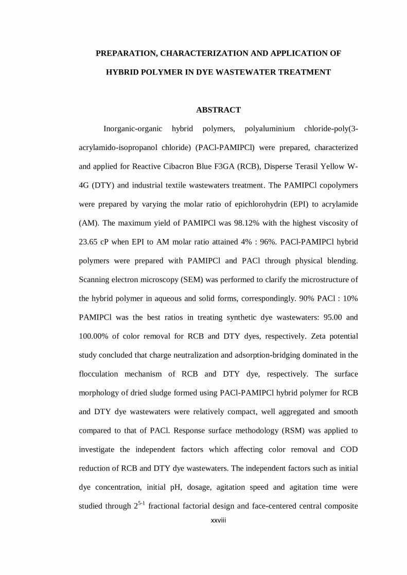
Inorganic-organic hybrid polymers, polyaluminium chloride-poly(3-
acrylamido-isopropanol chloride) (PACl-PAMIPCl) were prepared, characterized
and applied for Reactive Cibacron Blue F3GA (RCB), Disperse Terasil Yellow W-
4G (DTY) and industrial textile wastewaters treatment. The PAMIPCl copolymers
were prepared by varying the molar ratio of epichlorohydrin (EPI) to acrylamide
(AM). The maximum yield of PAMIPCl was 98.12% with the highest viscosity of
23.65 cP when EPI to AM molar ratio attained 4% : 96%. PACl-PAMIPCl hybrid
polymers were prepared with PAMIPCl and PACl through physical blending.
Scanning electron microscopy (SEM) was performed to clarify the microstructure of
the hybrid polymer in aqueous and solid forms, correspondingly. 90% PACl : 10%
PAMIPCl was the best ratios in treating synthetic dye wastewaters: 95.00 and
100.00% of color removal for RCB and DTY dyes, respectively. Zeta potential
study concluded that charge neutralization and adsorption-bridging dominated in the
flocculation mechanism of RCB and DTY dye, respectively. The surface
morphology of dried sludge formed using PACl-PAMIPCl hybrid polymer for RCB
and DTY dye wastewaters were relatively compact, well aggregated and smooth
compared to that of PACl. Response surface methodology (RSM) was applied to
investigate the independent factors which affecting color removal and COD
reduction of RCB and DTY dye wastewaters. The independent factors such as initial
dye concentration, initial pH, dosage, agitation speed and agitation time were
studied through 25-1
fractional factorial design and face-centered central composite

xxix
design (FCCD). All the independent factors were found to be statistically significant
in affecting color removal and COD reduction. The second-order model adequately
represented the experimental data of responses. The optimum operating conditions
to treat RCB dye wastewater are shown as follows: initial dye concentration of 170
mg/L, initial pH of 6.07, dosage of 30.00 mg/L, agitation speed of 100 rpm and
agitation time of 15 min. The predicted optimum color removal and COD reduction
are 98.85 and 66.00%, respectively. The optimum operating conditions to treat DTY
dye wastewater are shown as follows: initial dye concentration of 300 mg/L, initial
pH of 4.00, dosage of 30.00 mg/L, agitation speed of 300 rpm and agitation time of
3 min. The predicted optimum color removal and COD reduction are 100.00 and
85.47%, respectively. Finally, industrial textile wastewater attained 83.43% of color
removal and 79.17% of COD reduction with optimum conditions of 24.60 mg/L
hybrid polymer, pH 6.88, 300 rpm of agitation speed and 14 min of agitation time.
1
CHAPTER 1
INTRODUCTION
1.1 Overview of Textile Industry
Textile industry is one of the chemically intensive industries which demands
large amounts of water during manufacturing stages. The worldwide annual
production of dyes is approximately 7 × 10⁵ tons (Athalathil et al., 2014). In
Malaysia, textile industry is one of the fastest growing industries and highly
contributes to the economic growth (Pang and Abdullah, 2013). According to the
Malaysia Investment Performance Report (2012), the textile industry emerged as the
country’s 12th largest export earner contributing approximately RM 9.5 billion (1.4%)
to the country’s total exports of manufactured goods.
However, this industry requires high water consumption (approximately 100
to 200 L of water to process 1 kg of textile) and subsequently generates high
discharge rate as aqueous effluent with high load of complex chemical substances
(Department of Environment, 2000; Lotito et al., 2012). Wastewater generated from
different manufacturing unitary operations includes preparation, dyeing, soaping,
softening, finishing, etc. Effluent from textile industry contains different types of
dyes and persistent organics which is generally characterized by high alkalinity,
turbidity, temperature, chemical oxygen demand (COD), biochemical oxygen
demand (BOD), suspended solid and high intense color (Kim et al., 2004; Gao et al.,
2007; Verma et al., 2012).
The direct discharge of this toxic colorants effluent into environment affects
its ecological status as some of the dyes are carcinogenic and create a potential
health hazard to the aquatic biosphere (Wang et al., 2011b; Moghaddam et al., 2011;
2
Zahrim and Hilal, 2013). Among the commercial textile dyes, reactive and disperse
dyes are of great environmental concern due to their widespread use in dyeing
cotton and polyester (Chen et al., 2010). Reactive dyes have been considered as the
most problematic compound in textile wastewater due to their high water solubility
as well as high stability and persistence in nature (García Montaῆo, 2007). Non-
ionic disperse dyes have extremely low water solubility and complex chemical
structure that are resistant to typical aerobic degradation (Somasiri et al., 2006).
As environmental issue has become global concern, industrial effluent must
be treated before discharged into environment. According to the Environmental
Quality Act 1974 which was gazetted in the year of 2009 – Environmental Quality
(Industrial Effluent) Regulation 2009, the discharge of industrial effluent or mixed
effluent must comply with the Fifth Schedule (Environmental Quality Act 1974 (Act
127), Regulations, Rules & Orders, 2012). There are a total of 30 parameters as
stated in the Fifth Schedule (Table A1.1 in Appendix). Acceptable conditions for the
discharge of industrial effluent containing COD for specific trade or industry sectors
have been stated in the Seventh Schedule (Table A1.2 in Appendix).
As stated in the Fifth Schedule (Table A1.1 in Appendix), the discharge
limits of industrial effluent or mixed effluent of color in standard A and B are 100
and 200 ADMI, respectively. The ADMI (American Dye Manufacturers’ Institute)
weighted ordinate method was applied to measure colored waters and wastewaters
with color characteristics using platinum-cobalt (Pt-Co) unit (Allen et al., 1973). For
textile industry, the discharge limits of COD in standard A and B are 80 and 250
mg/L, respectively (Table A1.2 in Appendix). Standard A shows the limits that must
be complied for effluent to be discharged into any inland waters within the
catchment areas while Standard B lists the limits for effluent to be discharged into
3
any other inland waters. The regulation is related to the prevention, abatement,
control of pollution and enhancement of the environment.
1.2 Wastewater Treatment Methods
In common, wastewater treatment methods can be classified into three
categories: physical, chemical and biological. However, there is no single
economically and technically viable method in dye wastewater treatment
technologies. Usually, two or more treatment methods have to be combined in order
to attain a more efficient treatment (Robinson et al., 2001; Apollo et al., 2014; Cui et
al., 2014; Guieysse and Norvill, 2014). The removal efficiency of each method is
limited based on the specific dye chemical structure. This is the driving force for
researchers to constantly develop for new materials as well as processes to be
applied in physical, chemical and biological wastewater treatments (Jairton et al.,
2014).
Physical treatment involves processes where no gross chemical or biological
changes are carried out and only physical phenomena such as particle separation
processes are implemented to improve the wastewater. The processes that are
included in physical treatments are sedimentation (clarification), screening,
membrane filtration, flotation and skimming, degasification, equalization and the
most commonly applied adsorption (Fitzpatrick and Gregory, 2003; Konsowa et al.,
2010). Adsoption method is excellent in a wide variety of dye removal but the
limitations of this process are difficulties in adsorbent regeneration, excessive
maintenance costs and pre-treatment of wastewater to reduce the amount of
4
suspended solid before it can be fed into the adsorption column to avoid clogging
and blockage (Barredo-Damas et al., 2006; Hai et al., 2007).
Chemical treatment processes such as coagulation, flocculation, chlorination,
oxidation (ozonation, electro-chemical oxidation, photocatalysis, sonolysis),
neutralization and ion exchange involve a series of chemical reactions to enhance
the water quality. Plenty of physic-chemical methods operated in pre-treatment, post
treatment as well as main treatment have been studied by various researchers to
attain a better wastewater treatment. The main drawback of these processes is high
sludge generation (Azbar et al., 2004; Ciabatti et al., 2010). However, the sludge
production can be minimized by optimizing the operation parameters and selection
of appropriate coagulant and flocculant. Therefore, coagulation is still regarded as a
promising technology in wastewater treatment due to its high color removal
efficiency and cost effectiveness (Huang et al., 2009; Verma et al., 2012).
Biological treatment uses bacteria and other microorganisms to decompose
organic contaminants in wastewater into harmless or volatile compounds. Biological
treatment processes can be classified into aerobic (presence of oxygen) and
anaerobic (absence of oxygen) methods. According to Gavrilescu and Macoveanu
(1999), conventional aerobic process based on aerobic activated sludge process can
have high color removal efficiency and high operational flexibility. Nevertheless, the
huge energy consumed and high sludge production, which requires handling,
treatment and disposal increase the operation cost drastically (Sun et al., 2012b).
The conventional anaerobic treatment processes are feasible and cost effective but
they are time consuming and do not always provide satisfactory results, especially
when applied to industrial wastewater, since many of the containing organic
5
pollutants are toxic or resistant to biodegradation process (Oller et al., 2011;
Kushwaha et al., 2011; Pariente et al., 2013).
1.3 Hybrid Polymers in Coagulation-flocculation
Coagulation is a charge neutralization process on colloidal particles and
maintains the particles in suspension. The electrostatic repulsion force between
destabilized colloidal particles prevents colliding particles from aggregation.
Flocculation is a process of bridging the microscopic particles and slow-settling
colloidal particles into larger agglomerates in the presence of flocculant usually used
after coagulation (Teng et al., 2014).
Coagulation-flocculation is a commonly used in wastewater treatment due to
its high efficiency and cost effectiveness. Practical application has shown that
coagulation-flocculation minimizes the pollution load by optimizing the process
parameters and selection of suitable coagulant and flocculant (Ahmad et al., 2007;
Verma et al., 2012). Thus, treatment plant should be designed with higher energy
efficiency at a smaller footprint and built at lower investment costs with the smaller
load.
Various materials have been applied as coagulants. Among them are
inorganic metal salts with high cationic charges, such as aluminium sulphate (alum)
ferric sulphate (FeSO4) and ferric chloride (FeCl3) (Huang et al., 2014a).
Polyelectrolytes of inorganic-based flocculant, organic-based flocculant as well as
bioflocculant of various structures have been developed to assist the formation of
larger flocs with the purpose of improving the rate of sedimentation. Industry faces
increasing pressure to reduce pollutant discharge, water usage, and energy
6
consumption. The continuous raise of market demands for effective materials in
wastewater treatment has lead to development of hybrid polymers.
Recently, the use of hybrid polymers in wastewater treatment has grown
rapidly as hybrid polymers are reported to be more efficient compared to
conventional inorganic coagulants due to the synergism effect of two components in
one material (Lee et al., 2012a; 2012b; Liu et al., 2013; Yang et al., 2013; Dawood
and Li, 2014; Verma et al., 2014). The molecular weight (Mw) and size of inorganic
polymeric coagulant (IPC) is lower compared to those of organic polymeric
coagulant (OPC) (Moussas and Zouboulis, 2008). Thus, the aggregating capacity of
IPC remains lower. By introducing high Mw water soluble polymer such as
polyacrylamide (PAM) into inorganic coagulants for preparing the hybrid polymers,
the bridging capacity of the polymers will be enhanced.
1.4 Problem Statements
At present, the coagulation-flocculation process in the industry is still reliant,
to a very large extent, on experimental stage due to the extremely complex nature of
the process and the numerous types of polyelectrolytes available (Razali et al., 2011).
Hybrid polymers which composed of two or more different types of polymeric
matrix have recently received increasing attention due to their superior performance
in wastewater treatments compared to that of conventional organic or inorganic-
based flocculants (Moussas and Zoubolulis, 2009).
PAM-based hybrid flocculants with PAM combining with a wide variety of
inorganic coagulants have been reported by many researchers. For examples: alum
(El-Gohary and Tawfik, 2009), polyaluminium chloride (PACl) (Sanghi et al., 2006;
Tun et al., 2007), magnesium chloride (MgCl2) (Lee et al., 2012c), magnesium
7
hydroxide (Mg(OH)2) (Lee et al., 2012d), aluminium hydroxide (Al(OH)3) (Ani and
Li et al., 2012), FeCl3 (Lee et al., 2011c), etc. Besides, EPI-based hybrid flocculants
have been widely applied in water and wastewater treatment processes. In spite of
operating in wider effective pH range, EPI-based hybrid flocculants are easy to
handle and work effectively in lower dosage. This has directly led to reduction of
operating cost (Joo et al., 2003; Gao et al., 2011). Examples of EPI-based hybrid
flocculants are polyaluminium chloride-epichlorohydrin dimethylamine (PACl-EPI-
DMA) (Yue et al., 2008; Wang et al., 2009; Wang et al., 2011), polyferric chloride-
epichlorohydrin-dimethylamine (PFCl-EPI-DMA) (Chen et al., 2010; Gao et al.,
2011), etc.
Therefore, a hybrid copolymer of poly(3-acrylamido-isopropanol chloride)
(PAMIPCl)-based flocculant combined of PAM and epichlorohydrin (EPI) may look
promising in enhancement of wastewater treatment. Subsequently, in my continuing
pursuit for polymeric structures with the improved properties, new types of
inorganic-organic hybrid polymers, polyaluminium chloride-poly(3-acrylamido-
isopropanol chloride) (PACl-PAMIPCl) were synthesized to boost the aggregating
power of flocculant. PACl was selected to compose with PAMIPCl copolymer as
pre-hydrolyzed metallic salts have been proven to be more effective than the
hydrolyzing metallic salts such as alum, FeCl3 and FeSO4 (Verma et al., 2012; Lee
et al., 2012b).
Characteristics of the copolymers and hybrid polymers were studied to
predict the performance in wastewater treatment in both synthetic and industrial
wastewaters. Among the commercial textile dyes, reactive and disperse dyes are
chosen to determine the color removal and COD reduction efficiencies of PACl-
8
PAMIPCl hybrid polymer as these dyes have widespread applications and caused
great environmental concern. The present research also enhances our understanding
of hybrid polymer on the flocculation performance and gives better choices for
flocculant in industrial application such as textile industry which discharges large
volume of wastewater.
1.5 Objectives
The objectives of the present study include:
a. To prepare and characterize the chemical, physical and morphological
properties of PAMIPCl copolymers and PACl-PAMIPCl inorganic-organic hybrid
polymers.
b. To determine the flocculation mechanisms of PACl-PAMIPCl inorganic-
organic hybrid polymers in treating synthetic dyes.
c. To determine the effects of operating parameters (initial concentration of dye,
initial pH, dosage of PACl-PAMIPCl hybrid polymer, agitation speed and agitation
time) in order to optimize the coagulation-flocculation activity of PACl-PAMIPCl
inorganic-organic hybrid polymers in treating synthetic dyes and industrial textile
wastewater.
1.6 Scope of the Study
This present work can be divided into three stages. The first and second
stages involve the synthesis and characterization of PAMIPCl copolymers and
PACl-PAMIPCl hybrid polymers, respectively. Ammonium persulphate (NH4)2S2O8
and sodium bisulphite (NaHSO3) were used to initiate the redox polymerization of
9
PAMIPCl copolymers at 65°C by varying the molar ratio of EPI to acrylamide (AM).
The physicochemical properties of PAMIPCl copolymers were studied in terms of
chemical structure, conductivity, intrinsic viscosity and viscosity. PAMIPCl of the
highest viscosity was prepared when EPI to AM molar ratio attains 4% : 96%. This
may be due to intra and intermolecular associations. PACl-PAMIPCl hybrid
polymers were then prepared with PAMIPCl and PACl through physical blending.
PACl-PAMIPCl hybrid polymers were characterized in terms of chemical, physical
and morphological. In the third stage, the PACl-PAMIPCl hybrid polymers were
applied in treating synthetic dye wastewaters and industrial textile wastewater. Their
efficiency as flocculants was determined through color removal and COD reduction
in synthetic dyes and industrial textile wastewater. After coagulation-flocculation
treatment using PACl-PAMIPCl hybrid polymer, discharge of both synthetic and
industrial textile wastewaters shall be complied with the Environmental Quality Act
1974 of Fifth Schedule for color concentration (not more than 200 Pt-Co) and
Seventh Schedule for COD concentration (not more than 250 mg/L). The
flocculation mechanisms were studied through zeta potential () analyses.
10
CHAPTER 2
LITERATURE REVIEW
2.1 Textile Dye
Dyes are used in the coloration of wide variety of materials, including papers,
leathers, plastics as well as textile products. These dyes are aromatic compounds
associated with a side chain required for resonance and therefore to impart color.
Characterization of dyes is based on their chemical structure, functional group and
application. They are composed of the acceptor of electrons called chromophore and
the donor of electrons responsible for dyeing capacity, called auxochrome (Christie,
2001; Zee, 2002). The chromophore configurations are represented by azo (–N=N–),
methane (–CH=), ethenyl (–C=C–), ethylene (=C=C=), carbonyl (–C=O), carbon-
nitrogen (=C=NH; –CH=N–), carbon-nitrogen (=C=NH; –CH=N–), carbon-sulphur
(=C=S; ≡CS–S–C≡), imino (–C=N–), thiocarbonyl (–CH=S), nitroso (–N=O), nitro
(–NO2;-NO–OH), nitrozo (–N=O; =N–OH) and chinoid groups. Common
auxochrome is ionizable groups, including amino, (–NH2), carboxyl (–COOH),
sulphonyl (–SO3H) and hydroxyl (–OH) (Suteu et al, 2011; Zaharia and Suteu,
2012).The intensity of color depends upon the number of the groups. Compounds of
benzene naphthaline or antracene containing chromophore radicals are called
chromogens (Verma et al., 2012).
2.1.1 Textile Fibre
According to Christie (2001), textile fibres can be generally categorized as follows:
11
2.1.1.1 Natural fibre
Before 1856, the natural textile dyes were mainly used in textile processing. The
natural fibres are extracted from three main sources. There are plant (production of
cellulosic fibre), animal (production of protein fibre) and rock (mineral fibre).
Compared to synthetic fibre, natural fibre could only produce a shorter length of
fibre (staple yarn). The dimensional structure of natural fibre would be in hairiness
surface due to their origin (Welham, 2000). Natural fibre requires a long time to
restock the production although it is renewable sources. To ensure natural fibre can
compete well with synthetic fibre in terms of availability, countries such as China,
Australia, Sudan and Greece have their own farms or fields in order to meet the local
and world demands (Maxwell, 2003).
2.1.1.2 Synthetic / Man-made fibre
The first synthetic dye was mauve‘dye (aniline),a brilliant fuchsia color discovered
in 1856 synthesized by W.H. Perkin (UK), and subsequently some azo dyes were
synthesized by diazotization reaction discovered in 1958 by P. Gries (Germany)
(Welham, 2000). Unlike natural fibre, synthetic fibre is produced in a filament yarn
based on the end-use. The dimensional appearance of synthetic fibre can be varied
according to the demand usage. There are two basic types of synthetic fibre that
have been widely used by the textile industry: a) natural polymer-based and b)
synthetic-based (Collier and Tortora, 2001).
a) Natural polymer-based fibre or regenerated fibre is manufactured fibre that is
derived from natural cellulosic sources (wood pulp or cotton linters). New forms of
fibre will be produced after the compositions of cellulosic go through some
12
polymerization processes. Examples of natural polymer-based fibres include viscose
rayon, acetate and lyocell.
b) Synthetic-based fibre refers to a fibre that has been made totally by using
chemical substances. Examples of synthetic-based fibres include polyester,
polyamide (nylon), olefin, elastomeric and acrylic fibres.
2.1.2 Classification of Dye
The textile dyes are mainly classified based on their application
characteristics. They can belong to the class of acid, basic, direct, disperse, mordant,
reactive, sulphur, pigment or vat (Verma et al., 2012). 65 to 75% of textile dyes can
be classified through chemical structure, namely azo and anthraquinone. Azo dye,
characterized by reactive groups that form covalent bonds with –OH, –NH, or –SH
groups in fibre (cotton, wool, silk, nylon) is the most commonly used for yellow,
orange and red colors. Anthraquinone dye represents the second most significant
class of textile dyes and has a wide range of colors in almost the whole visible
spectrum, especially for violet, blue and green colors (Fontenot et al., 2003).
Considering only the general structure, the textile dyes can be categorized
into anionic, non-ionic or cationic dyes. The anionic dyes are mostly composed of
acid, direct and reactive dyes (Robinson et al., 2001). The major non-ionic dye is the
disperse dye and the major cationic dye is the azo basic. The most problematic dyes
are those which are composed of benzidine and aromatic components that are highly
carcinogenic and toxic to the biotic. For instances, naturally reactive dye is non-
toxic; however, under anaerobic conditions, they may break down into aromatic
amine (Zee and Villaverde, 2005; Zaharia and Suteu, 2012). The interactions
13
between dye molecules and the fibre are usually performed in aqueous media, which
involve many different types of chemical forces, such as ionic bond, covalent bond,
hydrogen bond, electrostatic attraction, intermolecular force and Van der Waals
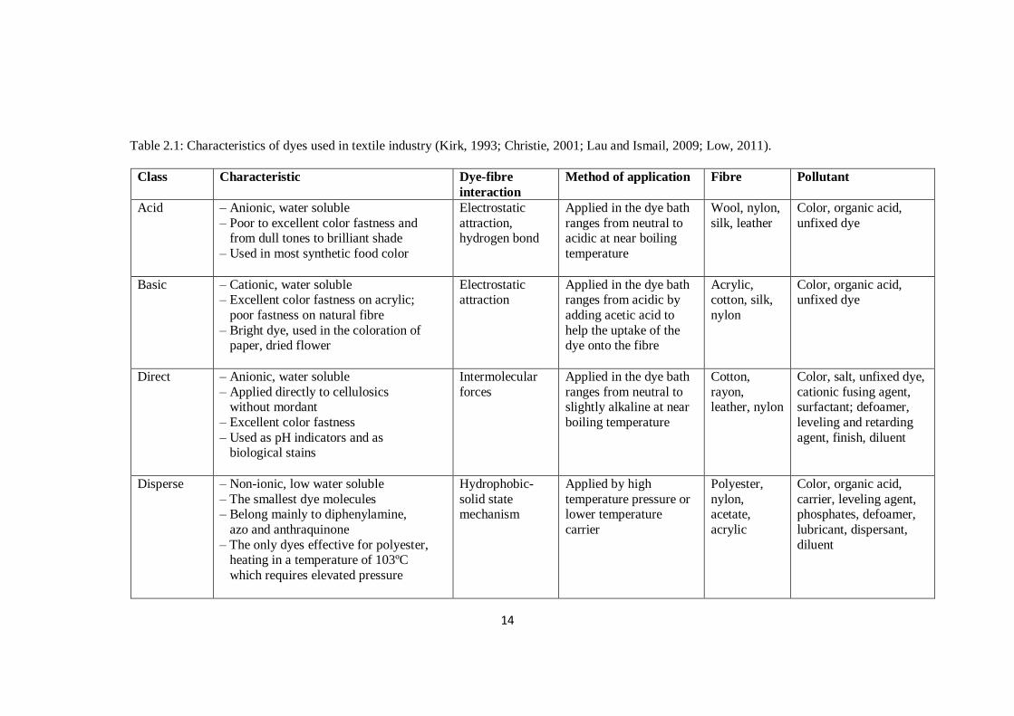
force (Jairton et al., 2014). The characteristics and types of pollutant of different
textile dyes are summarized in Table 2.1.
2.2 Treatment of Dye Wastewater
Treatment of textile industry wastewater remains a great challenge due to its
wide coverage of pH, COD, dissolved solids and variety of synthetic dyestuff. The
textile wastewater exhibits range of pH from 2 to 14, COD from 50 to 18,000 mg/L
and total dissolved solid (TDS) from 50 to 6000 mg/L. This wide variation in the
characteristics of textile wastewater is due to large numbers of chemical constituents
used in the textile industry during textile processing (Verma et al., 2012). A
complete set of treatment for dye wastewater usually requires a number of steps and
a combination of several treatment methods and purification before the maximal
efficiency/purity can be obtained. This is because each method has its own
advantages and disadvantages (Sher et al., 2013).
In general, wastewater treatment can be divided into four stages: preliminary
primary (physical), primary (physical), secondary (biological) and tertiary or
advanced (chemical) treatment (Gupta and Suhas, 2009). First, incoming raw
wastewater is passed through a series of screens, where the ranges of suspended
solids and BOD are reduced from 50 to 65% and 30 to 40%, respectively.
Subsequently, wastewater is pumped into secondary (biological) treatment, followed
by disinfection before discharge. When the standard of the effluent discharged from
the secondary treatment is unacceptable, tertiary or advanced wastewater treatment
14
Table 2.1: Characteristics of dyes used in textile industry (Kirk, 1993; Christie, 2001; Lau and Ismail, 2009; Low, 2011).
Class Characteristic Dye-fibre
interaction
Method of application Fibre Pollutant
Acid – Anionic, water soluble
– Poor to excellent color fastness and from dull tones to brilliant shade
– Used in most synthetic food color
Electrostatic
attraction, hydrogen bond
Applied in the dye bath
ranges from neutral to acidic at near boiling
temperature
Wool, nylon,
silk, leather
Color, organic acid,
unfixed dye
Basic – Cationic, water soluble – Excellent color fastness on acrylic;
poor fastness on natural fibre
– Bright dye, used in the coloration of paper, dried flower
Electrostatic attraction
Applied in the dye bath ranges from acidic by
adding acetic acid to
help the uptake of the dye onto the fibre
Acrylic, cotton, silk,
nylon
Color, organic acid, unfixed dye
Direct – Anionic, water soluble
– Applied directly to cellulosics without mordant
– Excellent color fastness
– Used as pH indicators and as biological stains
Intermolecular
forces
Applied in the dye bath
ranges from neutral to slightly alkaline at near
boiling temperature
Cotton,
rayon, leather, nylon
Color, salt, unfixed dye,
cationic fusing agent, surfactant; defoamer,
leveling and retarding
agent, finish, diluent
Disperse – Non-ionic, low water soluble
– The smallest dye molecules – Belong mainly to diphenylamine,
azo and anthraquinone
– The only dyes effective for polyester, heating in a temperature of 103ºC
which requires elevated pressure
Hydrophobic-
solid state mechanism
Applied by high
temperature pressure or lower temperature
carrier
Polyester,
nylon, acetate,
acrylic
Color, organic acid,
carrier, leveling agent, phosphates, defoamer,
lubricant, dispersant,
diluent
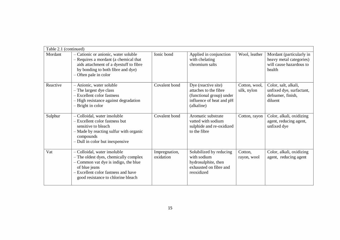
15
Table 2.1 (continued)
Mordant – Cationic or anionic, water soluble
– Requires a mordant (a chemical that aids attachment of a dyestuff to fibre
by bonding to both fibre and dye)
– Often pale in color
Ionic bond Applied in conjunction
with chelating chromium salts
Wool, leather Mordant (particularly in
heavy metal categories) will cause hazardous to
health
Reactive – Anionic, water soluble
– The largest dye class
– Excellent color fastness – High resistance against degradation
– Bright in color
Covalent bond Dye (reactive site)
attaches to the fibre
(functional group) under influence of heat and pH
(alkaline)
Cotton, wool,
silk, nylon
Color, salt, alkali,
unfixed dye, surfactant,
defoamer, finish, diluent
Sulphur – Colloidal, water insoluble
– Excellent color fastness but
sensitive to bleach
– Made by reacting sulfur with organic compounds
– Dull in color but inexpensive
Covalent bond Aromatic substrate
vatted with sodium
sulphide and re-oxidized
to the fibre
Cotton, rayon Color, alkali, oxidizing
agent, reducing agent,
unfixed dye
Vat – Colloidal, water insoluble
– The oldest dyes, chemically complex
– Common vat dye is indigo, the blue
of blue jeans – Excellent color fastness and have
good resistance to chlorine bleach
Impregnation,
oxidation
Solubilized by reducing
with sodium
hydrosulphite, then
exhausted on fibre and reoxidized
Cotton,
rayon, wool
Color, alkali, oxidizing
agent, reducing agent
16
must be employed. Nowadays, varies types of fundamental primary and secondary
treatments are used in sewage treatment plants for treating large quantities of sewage
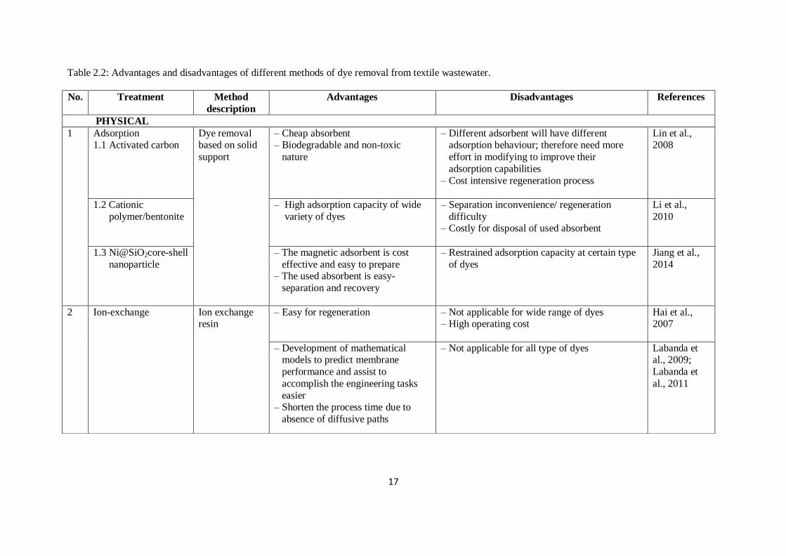
(Botkin and Keller, 2005). The relative advantages and disadvantages of the selected
treatment processes are summarized in Table 2.2.
2.3 Coagulation-flocculation
The most practised technology; coagulation-flocculation is widely applied on
industrial wastewater treatment. Typical applications are the removal of colloids
particles, natural organic matter, metal ions, color and odour. Coagulation-
flocculation has been employed for the treatment of wastewaters from tannery, yeast
wastewater, textile, petroleum refinery, dye house, aquaculture, municipal, landfill
leachates, pulping, olive mill and others (Sher et al., 2013; Papaphilippou and
Yiannapas, 2013).
The suspended materials and colloidal particles in water or wastewater
mostly originate from the dissolution of minerals, domestic and industrial waste
discharges. The materials or particles have to be removed, as they cause
deterioration of water quality by reducing the clarity, causing turbidity and infection.
Particles with the size 1.0 and 0.1mm may be known as coarse sand and fine sand;
respectively. Particles smaller than 0.00001 mm can be referred to as colloid (Bratby,
2006). With decrease of the particle size, the time required for settling increases,
from minutes to several years for certain solution ingredients.
To remove the tiny particles in wastewater, all the small particles should be
aggregated, then larger particles are formed which assist settling and finally
separation or filtration (Tzoupanos and Zouboulis, 2008). In nature, colloidal
particles normally carry charges on their surfaces, leading to stabilization of the
17
Table 2.2: Advantages and disadvantages of different methods of dye removal from textile wastewater.
No. Treatment Method
description
Advantages Disadvantages References
PHYSICAL
1 Adsorption 1.1 Activated carbon
Dye removal based on solid
support
– Cheap absorbent – Biodegradable and non-toxic
nature
– Different adsorbent will have different adsorption behaviour; therefore need more
effort in modifying to improve their
adsorption capabilities
– Cost intensive regeneration process
Lin et al., 2008
1.2 Cationic
polymer/bentonite
– High adsorption capacity of wide
variety of dyes
– Separation inconvenience/ regeneration
difficulty – Costly for disposal of used absorbent
Li et al.,
2010
1.3 Ni@SiO2core-shell
nanoparticle
– The magnetic adsorbent is cost
effective and easy to prepare – The used absorbent is easy-
separation and recovery
– Restrained adsorption capacity at certain type
of dyes
Jiang et al.,
2014
2 Ion-exchange Ion exchange resin
– Easy for regeneration – Not applicable for wide range of dyes – High operating cost
Hai et al., 2007
– Development of mathematical models to predict membrane
performance and assist to
accomplish the engineering tasks
easier – Shorten the process time due to
absence of diffusive paths
– Not applicable for all type of dyes Labanda et al., 2009;
Labanda et
al., 2011
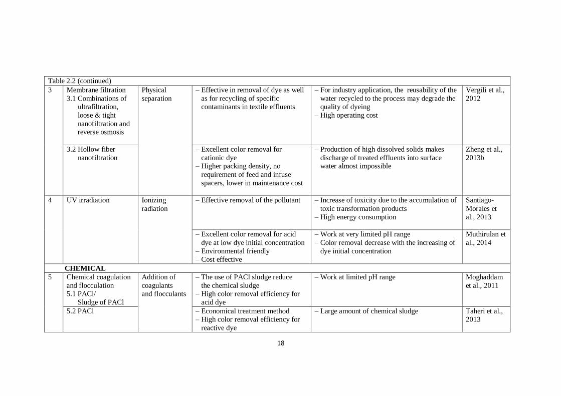
18
Table 2.2 (continued)
3 Membrane filtration
3.1 Combinations of ultrafiltration,
loose & tight
nanofiltration and reverse osmosis
Physical
separation
– Effective in removal of dye as well
as for recycling of specific contaminants in textile effluents
– For industry application, the reusability of the
water recycled to the process may degrade the quality of dyeing
– High operating cost
Vergili et al.,
2012
3.2 Hollow fiber
nanofiltration
– Excellent color removal for
cationic dye – Higher packing density, no
requirement of feed and infuse
spacers, lower in maintenance cost
– Production of high dissolved solids makes
discharge of treated effluents into surface water almost impossible
Zheng et al.,
2013b
4 UV irradiation Ionizing
radiation
– Effective removal of the pollutant – Increase of toxicity due to the accumulation of
toxic transformation products
– High energy consumption
Santiago-
Morales et
al., 2013
– Excellent color removal for acid
dye at low dye initial concentration
– Environmental friendly – Cost effective
– Work at very limited pH range
– Color removal decrease with the increasing of
dye initial concentration
Muthirulan et
al., 2014
CHEMICAL
5 Chemical coagulation
and flocculation 5.1 PACl/
Sludge of PACl
Addition of
coagulants and flocculants
– The use of PACl sludge reduce
the chemical sludge – High color removal efficiency for
acid dye
– Work at limited pH range
Moghaddam
et al., 2011
5.2 PACl – Economical treatment method – High color removal efficiency for
reactive dye
– Large amount of chemical sludge
Taheri et al., 2013
19
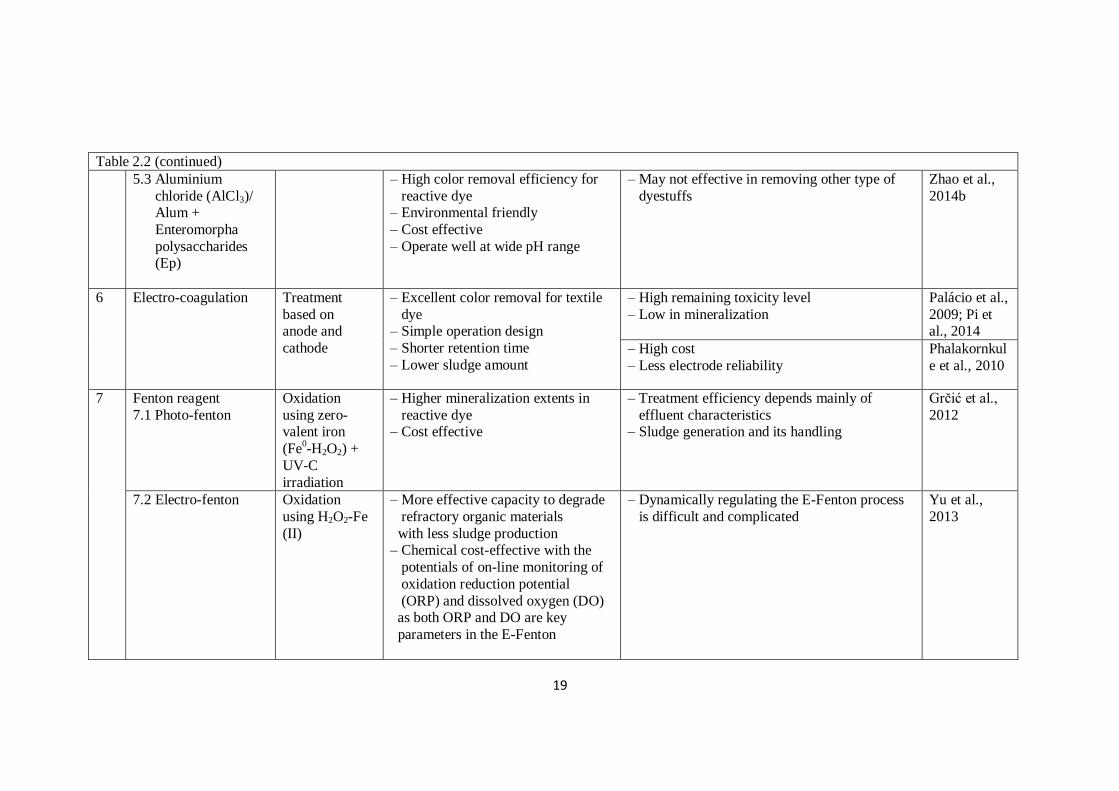
Table 2.2 (continued)
5.3 Aluminium
chloride (AlCl3)/ Alum +
Enteromorpha
polysaccharides (Ep)
– High color removal efficiency for
reactive dye – Environmental friendly
– Cost effective
– Operate well at wide pH range
– May not effective in removing other type of
dyestuffs
Zhao et al.,
2014b
6 Electro-coagulation Treatment
based on anode and
cathode
– Excellent color removal for textile
dye – Simple operation design
– Shorter retention time
– Lower sludge amount
– High remaining toxicity level
– Low in mineralization
Palácio et al.,
2009; Pi et al., 2014
– High cost
– Less electrode reliability
Phalakornkul
e et al., 2010
7 Fenton reagent
7.1 Photo-fenton
Oxidation
using zero-valent iron
(Fe0-H2O2) +
UV-C
irradiation
– Higher mineralization extents in
reactive dye – Cost effective
– Treatment efficiency depends mainly of
effluent characteristics – Sludge generation and its handling
Grčić et al.,
2012
7.2 Electro-fenton Oxidation
using H2O2-Fe
(II)
– More effective capacity to degrade
refractory organic materials
with less sludge production – Chemical cost-effective with the
potentials of on-line monitoring of
oxidation reduction potential
(ORP) and dissolved oxygen (DO) as both ORP and DO are key
parameters in the E-Fenton
– Dynamically regulating the E-Fenton process
is difficult and complicated
Yu et al.,
2013
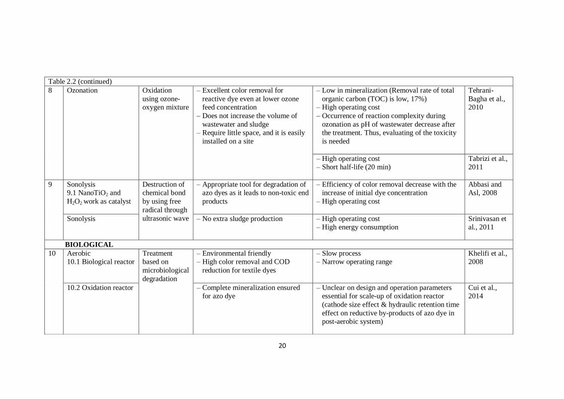
20
Table 2.2 (continued)
8 Ozonation Oxidation
using ozone- oxygen mixture
– Excellent color removal for
reactive dye even at lower ozone feed concentration
– Does not increase the volume of
wastewater and sludge – Require little space, and it is easily
installed on a site
– Low in mineralization (Removal rate of total
organic carbon (TOC) is low, 17%) – High operating cost
– Occurrence of reaction complexity during
ozonation as pH of wastewater decrease after the treatment. Thus, evaluating of the toxicity
is needed
Tehrani-
Bagha et al., 2010
– High operating cost – Short half-life (20 min)
Tabrizi et al., 2011
9 Sonolysis 9.1 NanoTiO2 and
H2O2 work as catalyst
Destruction of chemical bond
by using free
radical through
ultrasonic wave
– Appropriate tool for degradation of azo dyes as it leads to non-toxic end
products
– Efficiency of color removal decrease with the increase of initial dye concentration
– High operating cost
Abbasi and Asl, 2008
Sonolysis
– No extra sludge production
– High operating cost – High energy consumption
Srinivasan et al., 2011
BIOLOGICAL
10 Aerobic 10.1 Biological reactor
Treatment based on
microbiological
degradation
– Environmental friendly – High color removal and COD
reduction for textile dyes
– Slow process – Narrow operating range
Khelifi et al., 2008
10.2 Oxidation reactor – Complete mineralization ensured for azo dye
– Unclear on design and operation parameters essential for scale-up of oxidation reactor
(cathode size effect & hydraulic retention time
effect on reductive by-products of azo dye in post-aerobic system)
Cui et al., 2014
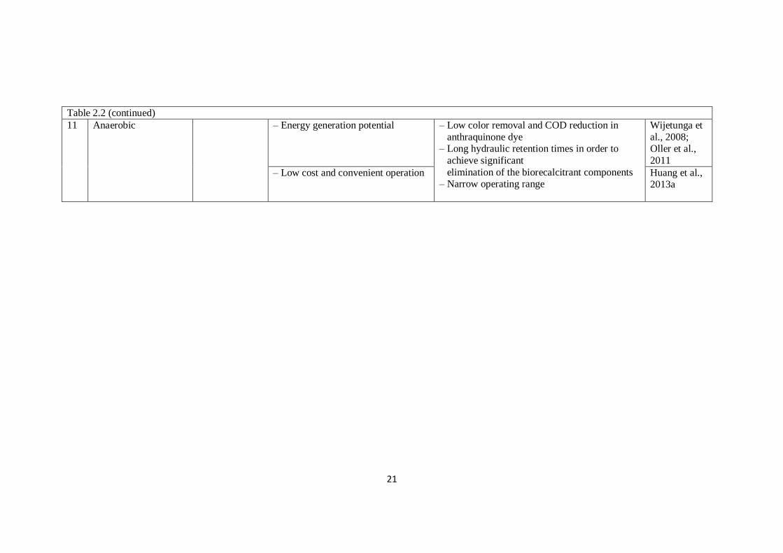
21
Table 2.2 (continued)
11 Anaerobic – Energy generation potential
– Low color removal and COD reduction in
anthraquinone dye – Long hydraulic retention times in order to
achieve significant
elimination of the biorecalcitrant components – Narrow operating range
Wijetunga et
al., 2008; Oller et al.,
2011
– Low cost and convenient operation Huang et al., 2013a
22
suspension. The charge structure surrounding the particle is called the electrical
double layer, which can be divided into stern and Gouy-Chapman layers. To
facilitate the particle of a stable dispersion to flocculate, sufficient kinetic energy
should be provided to the particle for overcoming the potential energy barrier. In
coagulation phase destabilization is stimulated either by the reduction of repulsive
forces between particles or by the enmeshment in precipitates. For insoluble
particles, such as minerals, inter-particle repulsion is typically caused by electrical
double layer interaction.
The surface potential (electrical potential difference between the particle
surface and the bulk solution) of colloidal particles will be affected by the addition
of some chemicals, either adsorption to the particle surface or by double layer
compression, facilitating the separation of particles by filtration. Chemicals that bind
at the surface of the particles may be due to multivalent cations and anions, ionic
surfactants and, H+ and OH
– ions bonding (Hogg, 2005; Harif et al., 2012). The
agglomerates formed by coagulation are smaller in size and loosely bound, whereas
the flocs formed by flocculation are of larger size and strongly bound (Tripathy and
Ranjan De, 2006).
2.3.1 Mechanism of Coagulation-flocculation
Coagulation-flocculation is a complex physiochemical process which
generally involves several different types of mechanism. Although the
destabilization process in neutral polymeric flocculant may occur by an increase in
Van der Waals attraction, this is regarded as being less critical compared to charge
neutralization (double layer compression), electrostatic patch and bridging
flocculation (adsorption of flocculant onto the particle surface) mechanisms
23
(Tripathy and Ranjan De, 2006). According to Lu et al. (2005), flocs formed by
bridging are entirely different from those formed by charge-patch neutralization.
These mechanisms will be further discussed at a later stage.
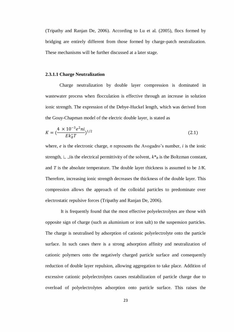
2.3.1.1 Charge Neutralization
Charge neutralization by double layer compression is dominated in
wastewater process when flocculation is effective through an increase in solution
ionic strength. The expression of the Debye-Huckel length, which was derived from
the Gouy-Chapman model of the electric double layer, is stated as
𝐾 = (4 × 10⁻³𝑒2𝑛𝑖
𝐸𝑘𝐵∗𝑇
)1/2 (2.1)
where, e is the electronic charge, n represents the Avogadro’s number, i is the ionic
strength, is the electrical permittivity of the solvent, k*B is the Boltzman constant,
and T is the absolute temperature. The double layer thickness is assumed to be 1/K.
Therefore, increasing ionic strength decreases the thickness of the double layer. This
compression allows the approach of the colloidal particles to predominate over
electrostatic repulsive forces (Tripathy and Ranjan De, 2006).
It is frequently found that the most effective polyelectrolytes are those with
opposite sign of charge (such as aluminium or iron salt) to the suspension particles.
The charge is neutralised by adsorption of cationic polyelectrolyte onto the particle
surface. In such cases there is a strong adsorption affinity and neutralization of
cationic polymers onto the negatively charged particle surface and consequently
reduction of double layer repulsion, allowing aggregation to take place. Addition of
excessive cationic polyelectrolytes causes restabilization of particle charge due to
overload of polyelectrolytes adsorption onto particle surface. This raises the

24
importance of the cationic polymer’s role on charge effects in the destabilization and
restabilization of negative colloids.
measurement within the entire flocculation process. Theoretically, when optimum
assumed to
be dominated by charge neutralization mechanism (Barany and Szepesszentgyorgyi,
2004; Zhao et al., 2014a).
negative at optimum flocculation with an increase in Mw of the polyelectrolytes.
This is because increasing Mw of polyelectrolytes favours bridging mechanism. The
charge density and Mw of polymers are critical in determining optimum flocculation
performances. With high Mw polyelectrolytes, bridging mechanism remains a
possibility, but the rather flat adsorbed configuration would be a limiting factor
(Gregory and Barany, 2011).
When charge neutralization becomes the dominant mechanism, flocs formed
are stronger and is more readily to reform when broken by high shear rates
compared to flocs formed through bridging mechanism (Lu et al., 2005).
Polyelectrolytes characteristics that favour charge neutralization are substantial
doses of a high charge density and low Mw polymer. Thus high charge density
cationic polyelectrolytes are effective in removing organic materials in wastewater
treatment. When the polymeric flocculants dose is low, electrostatic patch
mechanism dominates (Bolto, 2006).
2.3.1.2 Electrostatic Patch
The electrostatic patch mechanism proposed by Gregory (1973) usually
includes flocculation process characterized by cationic polymeric flocculants (high


