

Primary aluminium Casting alloys
RHEINFELDEN ALLOYS


Table of contents RHEINFELDEN ALLOYS
General
An overview of alloys
Alloys
Processing data sheets
Technical information
ALUMINIUM RHEINFELDEN Group
RHEINFELDEN FAST ALLOYS
Forms of delivery
Customer support, research and development
Overview of the alloy
Quick finder
Using tables to select alloy
Publications
Anticorodal ® – AlSi5 – 7Mg
Silafont ® – AlSi9 – 10 – 11 – 17Mg
Castaman ® – AlSi10MnMg
Castasil ® – AlSi9MnMoZr – AlSi9Sr
Unifont ® – AlZn10Si8Mg
Castadur ® – AlZn
Peraluman ® – AlMg3 – AlMg5Si
Magsimal ® – AlMg5Si2Mn
Aluman ® – AlMn
Alufont ® – AlCu
Thermodur ® – AlMg7Si3Mn – AlSi11Cu2
Generals to Processing data sheets
Anticorodal-70
Silafont-36
Castasil-37
Castadur-30
Unifont-90
Peraluman-56
Magsimal-59
Alufont-52
Generals to Technical informations
Chemical compositions
Mechanical properties
Physical properties
Properties at different temperatures
Mechanical properties under various influences
Grain refinement
Modification
Quality of melt and casting defects
Refining aluminium casting alloy melts
Melt testing
Artificial ageing – heat treatment – self-hardening
Heat treatment for high pressure die castings
Fatigue strength
Corrosion
Corrosion protection
Welded designs with aluminium castings
Joining techniques for die castings
Machining aluminium castings
2
4
5
6–7
8 – 11
12 – 13
14 – 15
16
17 – 24
25 – 34
35 – 36
37 – 40
41 – 44
45 – 46
47 – 50
51 – 54
55 – 56
57 – 60
61 – 63
64
65
66
67
68
69
70
71
72
73
74 – 75
76 – 77
78 – 79
80 – 81
82 – 83
84 – 86
87 – 91
92 – 93
94 – 95
96 – 97
98 – 103
104
105
106
107
108 – 109
110–111
112
1

ALUMINIUM RHEINFELDEN Group
“Fortschritt aus Tradition”
ALUMINIUM RHEINFELDEN Group: This history of aluminium
in Germany started at Rheinfelden. In 1898 Europe’s first
river power station brought about the establishment of the first
aluminium smelter in Germany, at Rheinfelden, Baden.
The company has always operated in three business segments
and in October 2008 restructuring turned ALUMINIUM
RHEINFELDEN GmbH into a holding company and the former
ALLOYS, SEMIS and CARBON divisions became independent
GmbH & Co. KGs (the German equivalent to a limited partner-
ship with a limited liability company as general partner).
www.rheinfelden-group.eu
Our policy
RHEINFELDEN ALLOYS GmbH & Co. KG is an innovative
manufacturer of aluminium cast alloys, able to rapidly adapt to
changing market requirements. The company is sited at the
heart of Europe’s heterogeneous casting market, a market which
places very varied requirements on aluminium. This location
offers benefits, as does the agility of this owner-managed
company and the wealth of experience which staff have gained
over the years.
When we develop new materials we always aim to achieve
efficient and careful use of aluminium casting. Through the use
of materials tailored and refined to increase performance,
RHEINFELDEN ALLOYS is constantly striving to help reduce
vehicle weight and therefore cut fuel consumption and emissions.
2

RHEINFELDEN ALLOYS GmbH & Co. KG: RHEINFELDEN
ALLOYS can be found wherever steel designs or iron castings
can be replaced by light aluminium castings. RHEINFELDEN
ALLOYS is a powerful partner, especially to the automotive and
mechanical engineering sectors, providing alloys tailored to the
process and cast part in line with the customer’s particular needs.
www.rheinfelden-alloys.eu · Tel. +49 7623 93 490
RHEINFELDEN SEMIS GmbH & Co. KG: Primary aluminium
slugs, blanks and pre-cut parts in a great variety of dimensions
form the primary material for tubes, cans and containers and for
technical applications.
www.rheinfelden-semis.eu · Tel. +49 7623 93 464
RHEINFELDEN CARBON GmbH & Co. KG: Ramming pastes
for the aluminium and ferro-alloy industry, gas calcined anthracite
and Soederberg pastes for the manufacture of high-purity ferro-
alloys and silicon.
www.rheinfelden-carbon.eu · Tel. +49 7623 93 211
Panoramic view of the entire complex
3
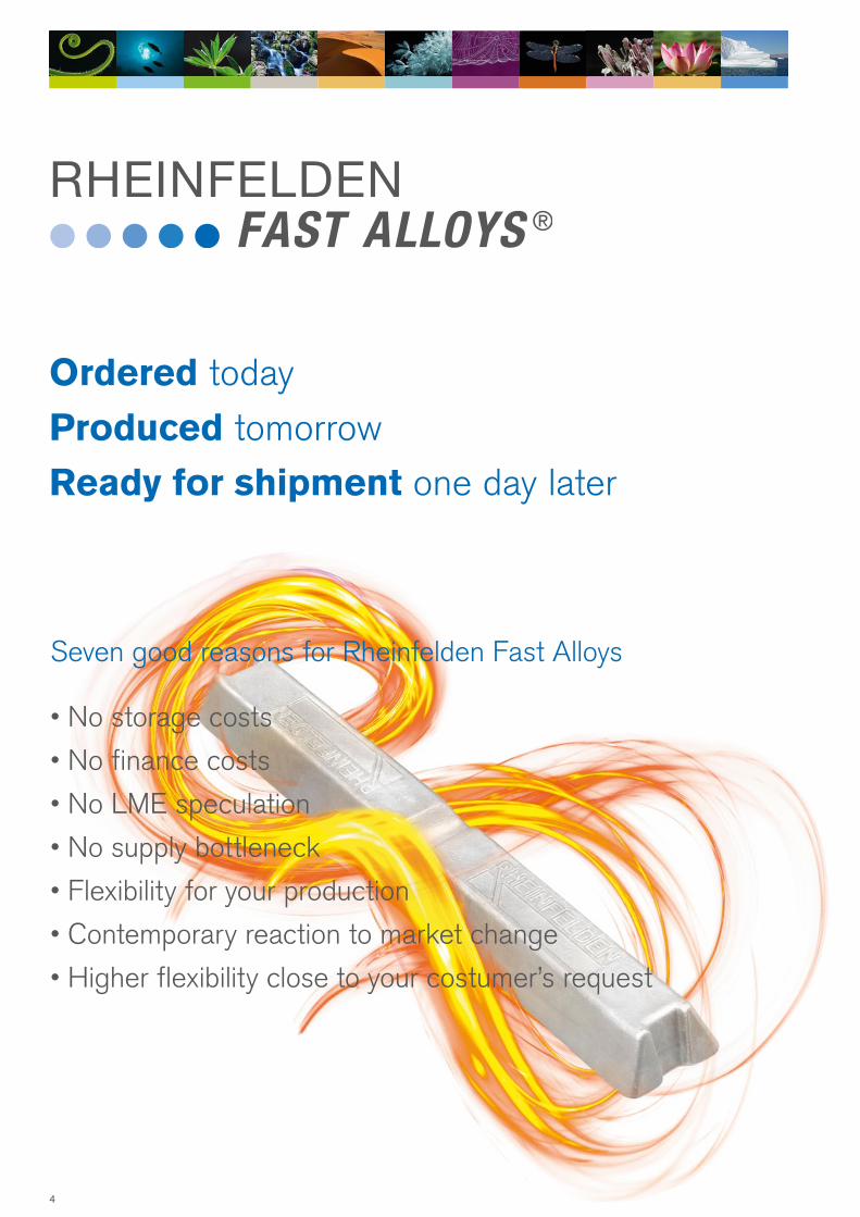
Seven good reasons for Rheinfelden Fast Alloys
• No storage costs
• No finance costs
• No LME speculation
• No supply bottleneck
• Flexibility for your production
• Contemporary reaction to market change
• Higher flexibility close to your costumer’s request
Ordered today
Produced tomorrow
Ready for shipment one day later
4

Forms of delivery
RHEINFELDEN Ingot: Since the new RHEINFELDEN Production System came on line, all our
materials have been supplied in the form of RHEINFELDEN ingots. This ingot form is replacing
the HSG ingot yet retains all the advantages of the old form of delivery.
Liquid metal: If you want us to deliver metal to go straight into production, we can also supply
liquid metal.
Analysis: The delivery slip contains the average actual batch analysis.
Stack labelling: Each stack features an information label containing the brand name and/or alloy
group name, internal material number, stack weight and on request a colour marking. The batch
number consists of the year in the sequential production number and the number in the sequenze.
Machine-readable bar codes can be printed in this label.
RHEINFELDEN-Ingot
The stack of RHEINFELDEN ALLOYS is built
with 95 single ingots including the 4 base ingots;
here the stack with 13 layers of ingots.
Ingot
Weight 6 – 8 kg
Base area 716 × 108 mm
Height up to 52 mm
Stack of 13 layers
Stack weight up to 760 kg
Base area 716 × 716 mm
Stack height up to 780 mm
5
Customer support and research and development
Every product and every customer has individual requirements of the material. The customer
Support team at RHEINFELDEN ALLOYS has the job of anticipating these needs and producing
tailored materials, fitting the castings and your requirements.
RHEINFELDEN customer support
Please contact our customer support team and use our TechCenter installations at RHEINFELDEN
ALLOYS also for your foundry concerns.
We can advise on the use of aluminium casting, the design of castings and the choice of alloy.
We can help you overcome casting problems and shed light on why you are producing rejects.
We also share our knowledge of the processing, welding and surface treatment of aluminium
casting. We can conduct metal analyses, microstructural analyses and mechanical strength
measurements on your behalf.
A wide range of publications and processing data sheets are also available.
www.rheinfelden-alloys.eu
The customer support team at RHEINFELDEN ALLOYS is your partner in the concern of using
aluminium casting alloys. We stand at your side if there comes up the question to design or cast an
aluminium casting product.
Use our experience for your success.
RHEINFELDEN technical centre
We operate a casting materials technical centre in Rheinfelden to enable us to provide a high-class
customer service and to develop our cast alloys in line with the market’s needs.
Time is increasingly of the essence when our customers experience casting technology problems.
It is therefore crucial that we have the facilities to allow us to quickly solve problems through
experimentation and immediately incorporate new findings into production. This technical support,
renowned throughout the industry, is available exclusively to RHEINFELDEN ALLOYS customers.
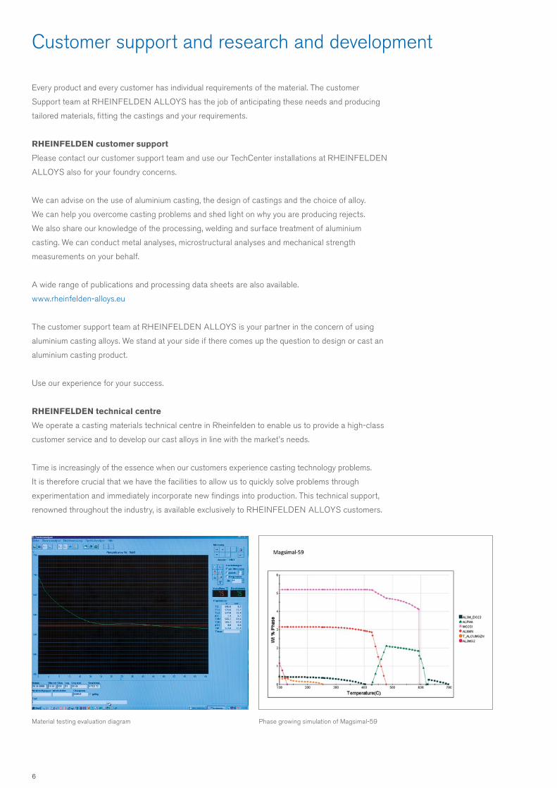
Phase growing simulation of Magsimal-59Material testing evaluation diagram
6

The goals of research and development
The technical centre assists the customer support team and runs development projects with the
following goals:
• To optimise the mechanical and casting properties of our aluminium casting alloys
• To develop alloys under consideration of the appropriate casting method
• To collaborate with designers on use of our casting alloy most suited to the materials,
including testing mechanical properties
• To simplify metallurgical work in our customers’ foundries
Our technical centre is equipped with labs for metallography, spectral analysis and casting material
testing, enabling structural analyses, tensile testing, component testing and other analyses to be
performed.
We at RHEINFELDEN ALLOYS development use also phase simulation software for calculations
and optimization of our wide range of casting alloys. Highlighted is here the solidification and phase
growing simulation of Magsimal-59.
First of all there is still a lot of practice needed before simulate a new alloy composition.
International links, for example with WPI, Worcester USA, Vincenza university, RWTH Aachen,
TU Clausthal, Fraunhofer Institut, STZ Esslingen and Friedrichshafen, allow further analyses to
be undertaken. These include dynamic material and component testing, mechanical properties at
elevated temperatures, corrosion behaviour, quantitative structural analysis and electron-optical
analysis (scanning electronmicroscope, qualitative microanalyse etc.).
We want to offer the heterogeneous market a wide range of customised aluminium casting alloys
for investment casting, sand and chill casting, as well as for HPDC which satisfy customers’ specific
application and processing requirements. RHEINFELDEN ALLOYS has set itself the goal of
supplementing aluminium’s natural lightness with the strength and forming properties required to
enable it to help cut emissions in automotive engineering.
RHEINFELDEN sales service
The portfolio of RHEINFELDEN ALLOYS sales department is always adjusted to the request of
our costumer. RHEINFELDEN ALLOYS has the possibility to offer different commercial strategies.
RHEINFELDEN Internet portal
www.rheinfelden-alloys.eu
7

The alloys we offer
As Anticorodal alloys can be adapted to virtually all different fields of work and production
methods, countless possible uses are emerging for this material. Outstanding mechanical
properties, electrical conductivity, corrosion resisting thanks to low silicon content, but slightly
harder to cast. As with Silafont alloys, to ensure cost-effective use, it is well worth providing a
complete definition of the material being used and tailoring it to both the parts to be produced
and your production process.
The creatures of the sea provide the natural metaphor for this alloy. Such creatures adapt to
different conditions and have developed a whole series of special attributes in order to do this.
> page 17
Anticorodal ® – infinitely adaptable
A family of materials which can be adapted to the parts to be produced and the customer’s
individual production process with ultimate precision. Can be processed using any casting
procedure, outstanding flow properties, can be modified with sodium or strontium to further
enhance its properties. For complex, delicate components which have to satisfy precisely
defined requirements and, if they feature the right components, make maximum production
efficiency possible.
Silafont emulates flowing water, that flows continually to the sea, advances at any angle,
washing around every stone and every shape in its way. Homogeneous and easily in the very
same way that Silafont fills the cavities in the mould.
> page 25
Silafont ® – an infinite wealth of properties
8

An alloy, produced for large, high pressure die cast structural parts in the automotive con-
struction industry. Lamborghini produced the first series in the Gallardo Spyder.
Numerous manufacturers now recognise the benefits of this alloy: high dimensional stability,
can be used without heat treatment, shapes well and easy to weld.
Nature’s equivalent: the vine branch which turns towards the sun, flexible, elastic and yet
incredibly tough and strong.
> page 37
Castasil ® – large areas, high dimensional stability, fantastic to cast
Unifont alloys offer high strength without heat treatment and outstanding casting properties,
but limited shaping properties. They are used for components which are often large and diffi-
cult, especially in circumstances which require high strength levels: in mechanical engineering,
domestic appliances and medical technology. Thanks to their self-hardening character, they
regenerate themselves after thermal overload.
Nature’s role model: the water lily which closes its petals for protection at night and only opens
them again when the sun rises.
> page 41
Unifont ® – high strenght and regenerative powers
An alloy family, that use the possibilities of recycling, to a desired high sustainability –
to come represented in carbon footprint counter.
Nature’s role model: the lupine, growing from the humus of last year’s crop.
> page 35
Castaman ®
9

Thanks to their absolute corrosion resistance and associated resistance to acids and salts,
these alloys are used to manufacture machines for the production of foodstuffs. The parts are
impact resistant and display good elongation. Their particularly soft sheen and their ability to
anodise in colour enable them to be used in places where looks are important.
The metaphor from nature for this alloy is soft coral. It is gracefully structured and appears
bright in dark water – it has the same matt sheen as parts produced from Peraluman.
> page 47
Peraluman ® – beautiful, soft sheen, impact resistant and tensile
An alloy for delicate parts which need to retain their strength and precise form over a long
period. Good weldability, high resilience, can be used in virtually any application. Supreme
corrosion resistance, even to salt water.
Parts which simulate the structure of the wings of a dragonfly: wafer thin, elastic and yet offer-
ing incredible strength and resilience, they enable this dainty insect to fly distances that never
cease to amaze.
> page 51
Magsimal ® – of filigree lightness, but extremely resilient
A self-hardening material of high formability which gains strength without losing its ability to
stretch. And even if it loses its properties, from overheating for example, they return. Castadur’s
softly radiant surface is easy to polish, making it popular for everyday objects such as furniture.
The material’s homogeneity and silent power are reminiscent of desert sand dunes, which,
shaped by the wind, are always taking on new shapes while remaining the same.
> page 45
Castadur ® – the power of regeneration
10
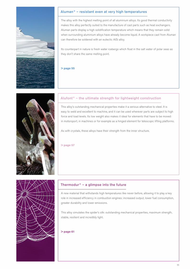
A new material that withstands high temperatures like never before, allowing it to play a key
role in increased efficiency in combustion engines: increased output, lower fuel consumption,
greater durability and lower emissions.
This alloy simulates the spider’s silk: outstanding mechanical properties, maximum strength,
stable, resilient and incredibly light.
> page 61
Thermodur ® – a glimpse into the future
This alloy’s outstanding mechanical properties make it a serious alternative to steel. It is
easy to weld and excellent to machine, and it can be used wherever parts are subject to high
force and load levels. Its low weight also makes it ideal for elements that have to be moved:
in motorsport, in machines or for example as a hinged element for telescopic lifting platforms.
As with crystals, these alloys have their strength from the inner structure.
> page 57
Alufont ® – the ultimate strength for lightweight construction
The alloy with the highest melting point of all aluminium alloys. Its good thermal conductivity
makes this alloy perfectly suited to the manufacture of cast parts such as heat exchangers.
Aluman parts display a high solidification temperature which means that they remain solid
when surrounding aluminium alloys have already become liquid. A workpiece cast from Aluman
can therefore be soldered with an eutectic AlSi alloy.
Its counterpart in nature is fresh water icebergs which float in the salt water of polar seas as
they don’t share the same melting point.
> page 55
Aluman ® – resistant even at very high temperatures
11

Quick finder for selecting the right alloyThe first step in producing a casting is to select the alloy most suited to the production process and requirements.
The table covering these two pages provides an overview of our most common materials, their areas of use and properties.
It will help you chose the right casting material. This table is no substitute for the service provided by our technical advisors,
but does provide an overview and allows users to access the information as and when they need it.
AlloyChemical denomination A
rchi
tect
ure
Fitt
ings
Car
s
Bui
lder
’s h
ardw
are
Ligh
ting
Airc
raft
Hea
vy c
astin
gD
omes
tic a
pplia
nces
Ele
ctric
al c
ondu
ctor
sA
ir co
nditi
onin
g
Man
ufac
ture
of e
ngin
esA
rt c
astin
g
Food
stuf
fs in
dust
ryM
echa
nica
l eng
inee
ring
Mod
el/m
ould
con
stru
ctio
nO
ptic
s/fu
rnitu
reS
hipb
uild
ing
Text
ile in
dust
ryD
efen
ce e
ngin
eerin
g
Che
mic
al in
dust
ry
Aut
omot
ive
engi
neer
ing
Areas of use
Anticorodal-04 AlSi0.5Mg
Anticorodal-50 AlSi5Mg
Anticorodal-70 AlSi7Mg0.3
Anticorodal-78dv AlSi7Mg0.3
Anticorodal-71 AlSi7Mg0.3 - E
Anticorodal-72 AlSi7Mg0.6
Silafont-30 AlSi9Mg
Silafont-36 AlSi10MnMg
Silafont-38 AlSi9MnMgZn
Silafont-09 AlSi9
Silafont-13 AlSi11
Silafont-20 AlSi11Mg
Silafont-70 AlSi12CuNiMg
Silafont-90 AlSi17Cu4Mg
Castaman-35 AlSi10MnMg
Castasil-37 AlSi9MnMoZr
Castasil-21 AlSi9Sr
Unifont-90 AlZn10Si8Mg
Unifont-94 AlZn10Si8Mg
Castadur-30 AlZn3Mg3Cr
Castadur-50 AlZn5Mg
Peraluman-30 AlMg3
Peraluman-36 AlMg3Si
Peraluman-50 AlMg5
Peraluman-56 AlMg5Si
Magsimal-59 AlMg5Si2Mn
Alufont-47 AlCu4TiMg
Alufont-48 AlCu4TiMgAg
Alufont-52 AlCu4Ti
Alufont-60 AlCu5NiCoSbZr
Thermodur-72 AlMg7Si3Mn
Thermodur-73 AlSi11Cu2Ni2Mg2Mn
Rotoren-Al 99.7 Al99.7 - E
Aluman-16 AlMn1.6
x x x x x
x x x x x x x x x x x x
x x x x x x x x x x x x x x x x
x x x x x x x x x x x
x
x x x x x x x x x x
x x x x x x x x x x x x x x
x x x x x x x x x x x x
x x x x x x x x x x
x x x x x x x x x x
x x x x x x
x x x x x x
x x
x x
x x x x x x x x x x
x x x x x x x x x x x
x x x x x x x
x x x x x x x
x x x x
x x x x x x x x
x x x x x x x
x x x x x x x x x x x x x
x x x x x x x x x x x x
x x x x x x x x x x x
x x x x x x x x x x x
x x x x x x x x x x x x
x x x x x
x x x x x
x x x x x x
x x x
x x x x x x x x
x x x x x x
x x x x x x x
x x x x
12

excellent
very good
good
all right
poor
not applicable–Distinguishing properties
San
d c
ast
ing
Gra
vity
die
ca
stin
g
Hig
h p
ress
ure
die
ca
stin
g
Appropriate casting method
Flan
geab
ility
Ele
ctric
al c
ondu
ctiv
ityS
uita
ble
for d
ecor
ativ
e an
odis
ing
Sui
tabl
e fo
r tec
hnic
al a
nodi
sing
Sui
tabl
e fo
r pun
ch r
ivet
ing
Str
engt
h in
as-
cast
sta
teC
astin
g pr
oper
ties
Elo
ngat
ion
Har
dnes
s
Cor
rosi
on re
sist
ance
For c
onst
ruct
ions
with
thic
k w
alls
Har
d so
lder
abili
tyM
axim
um s
tren
gth
at 2
0 °C
Res
ista
nce
to s
alt w
ater
Pol
isha
bilit
y
Impa
ct to
ughn
ess /
duc
tility
Wel
dabi
lity
Mac
hina
bilit
y fo
llow
ing
T6W
ear r
esis
tanc
e
Mac
hina
bilit
y at
F
For c
onst
ruct
ions
with
thin
wal
ls
Mec
hani
cal p
rope
rtie
s at
ele
vate
d
tem
pera
ture
s (2
00
°C)
x x x x x
x x x x x x x x x x x x
x x x x x x x x x x x x x x x x
x x x x x x x x x x x
x
x x x x x x x x x x
x x x x x x x x x x x x x x
x x x x x x x x x x x x
x x x x x x x x x x
x x x x x x x x x x
x x x x x x
x x x x x x
x x
x x
x x x x x x x x x x
x x x x x x x x x x x
x x x x x x x
x x x x x x x
x x x x
x x x x x x x x
x x x x x x x
x x x x x x x x x x x x x
x x x x x x x x x x x x
x x x x x x x x x x x
x x x x x x x x x x x
x x x x x x x x x x x x
x x x x x
x x x x x
x x x x x x
x x x
x x x x x x x x
x x x x x x
x x x x x x x
x x x x
—
—
—
—
—
—
— —
— —
— —
—
—
– –
— —
— —
—
— —
—
— —
—
–
—
—
— —
—
—
—
—
—
–
– – – –
– – –
– – –
– – – – – –
– – –
– – – – – – –
– – – –
– – – – – –
– – – – – –
– – – –
– – – – – –
– – – – – – – –
– – – – – – – –
– – – – –
– – – – – –
– – – – –
– – – – – – – –
– – – – – – – – –
– – – – – – –
– – – – – – –
– – – – –
– – – – – –
– – – – –
– – – – – –
– – – –
– – – – – – –
– – – – – – –
– – – – – – –
– – – – – – – –
– – – – –
– – – – – – – –
– – – –
– – – –
13

Tables for selecting alloys
The tables will aid designers in selecting the suitable casting alloy for the casting they are producing.
They contain details of the 0.2 % yield tensile strength, elongation and corrosion resistance.
The values indicate the performance of the alloys which can be achieved through appropriate casting
technology work in the casting or its sub-sections.
Sand casting, as-cast state
Anticorodal-70/ -78 dv Silafont-30 Peraluman-30/ -36Peraluman-50
Anticorodal-50Peraluman-56Castadur-50
Silafont-70Silafont-20
Silafont-13
Unifont-90 T1Thermodur-73
90 – 160 200 – 23060 – 120
6 – 1
33
– 6
0,5
– 3
0,2 % yield tensile strength Rp0,2 [MPa]
Elo
ngat
ion
A [
%]
Castadur-30
160 – 300 300 – 45090 – 160
4 –
82
– 5
0,3
– 3
0,2 % yield tensile strength Rp0,2 [MPa]
Elo
ngat
ion
A [
%]
Peraluman-56 T6 Anticorodal-50 T6Anticorodal-72 T6Silafont-20 T6Silafont-70 T6
Anticorodal-70/-78 dv T6Silafont-30 T6Peraluman-36
Alufont-47 T6Alufont-48 T6Alufont-52 T6
Anticorodal-50 T4Alufont-47 T4Alufont-48 T64Alufont-52 T64
Anticorodal-70/-78 dv T64Silafont-13 OPeraluman-30 T6
Sand casting, heat-treated
90 – 180 180 – 26070 – 100
6 –
202
– 6
0,5
– 2
0,2 % yield tensile strength Rp0,2 [MPa]
Elo
ngat
ion
A [
%]
Silafont-70Silafont-90Thermodur-73
Anticorodal-50Anticorodal-70Silafont-30Peraluman-56
Peraluman-30 Silafont-13Silafont-20Peraluman-50
Unifont- 90 T1
Gravity die casting, as-cast state
Peraluman-36
Thermodur-72
14

200 – 300 300 – 450120 – 200
8 – 1
24
– 8
0,5
– 4
0,2 % yield tensile strength Rp0,2 [MPa]
Elo
ngat
ion
A [
%]
Anticorodal-50 T6 Silafont-70 T6Silafont-90 T6Alufont-36 T6
Alufont-47 T6Alufont-48 T6Alufont - 52 T6
Anticorodal-70/-78 dv T6Anticorodal-72 T64Silafont-30 T6Silafont-20 T6
Anticorodal-50 T4Peraluman-56 T6
Anticorodal-70/-78 dv T64Silafont-13 OPeraluman-30 T6
Alufont-47 T4Alufont-52 T64
Gravity die casting, heat-treated
High pressure die casting
0,2 % yield tensile strength Rp0,2 [MPa]
Elo
ngat
ion
A [
%]
5 –
201 –
5– 1
Anticorodal-04Silafont-36 T4Aluman-16Castasil-21
Silafont-09Silafont-36Magsimal-59Castasil-37Silafont-36 T5 / T7Thermodur-72Castaman-35
Silafont-36 T6Silafont-38 T6
Unifont-94 T1
Silafont-90 Thermodur-73
120 – 220 220 – 28080 – 120
Silafont-38
Corrosion resistance
good very goodaverage excellent
Castability
Cor
rosi
on r
esis
tanc
e
with surface protection
from weathering
from salt water
Alufont-47/-48Alufont-52/-60Silafont-90
Silafont-70Thermodur-73
Silafont-30Unifont-90Unifont-94Castasil-37Castasil-21
Silafont-13Silafont-20Silafont-09Silafont-36 /-38Castaman-35
Anticorodal-04Peraluman-30/-36Peraluman-50/-56
Anticorodal-50Anticorodal-70/-78dvAnticorodal-71Anticorodal-72
Magsimal-59Thermodur-72
Castadur-30/-50
Treatment state
F As-cast state T4 Naturally aged T6 Artifically aged
O Annealed T5 Stabilised T64 Partially aged
T1 Self-aged T5 Quenched and aged T7 Overaged
15

Publications
www.rheinfelden-alloys.eu
Catalogues Code
Primary aluminium casting alloys Manual
Primary aluminium casting alloys Leporello
Primary Aluminium Alloys for Pressure Die Casting Manual
Manuals and processing data sheets
Anticorodal-04 Ac-04 507
Anticorodal-50 Ac-50 504
Anticorodal-70/72 Ac-70, Ac-72 501
Anticorodal-71 Ac-71 508
Silafont-30 Sf-30 511
Silafont-36 Sf-36 518
Silafont-38 Sf-38 519
Silafont-09 Sf-09 516
Silafont-13 Sf-13 513
Silafont-20 Sf-20 512
Silafont-70 Sf-70 515
Castaman-35 Cm-35 571
Castasil-21 Ci-21 562
Castasil-37 Ci-37 561
Unifont-90 Uf-90 531
Unifont-94 Uf-94 532
Peraluman-30/36 Pe-30, Pe-36 541
Peraluman-50/56 Pe-50, Pe-56 542
Magsimal-59 Ma-59 545
Alufont-52 Af-52 521
Alufont-47 Af-47 522
Alufont-48 Af-48 523
Thermodur-72 Td-72 563
Thermodur-73 Td-73 562
Aluminium for rotors RB 551
16

Anticorodal ® – infinitely adaptable
As Anticorodal alloys can be adapted to virtually all different
fields of work and production methods, countless possible uses
are emerging for this material. Outstanding mechanical proper-
ties, electrical conductivity, corrosion resisting thanks to low silicon
content, but slightly harder to cast. As with Silafont alloys, to enjoy
cost-effective use, it is well worth providing a complete definition
of the material being used and tailoring it to both the parts to be
produced and your production process.
The creatures of the sea provide the natural metaphor for this alloy.
Such creatures adapt to different conditions and have developed a
whole series of special attributes in order to do this.
17

Areas of use
For castings with high electrical conductivity. Electrical conductors, foodstuffs industry, mechanical engineering,
optics/furniture, chemical industry
Distinguishing characteristics
Alloy for medium strength and medium hardness electrical conductors. Best corrosion resistance, very good weldability and
suitable for decorative anodising (with the exception of high pressure die casting). Very well suited to hard soldering.
Alloy denomination
Chemical denomination: AlSi0.5Mg
Chemical composition [ % of mass]
Mechanical properties
Anticorodal ®- 04 [ AlSi0.5Mg ]
Conductors for high-voltage systems Anticorodal-04, overaged Sand casting, ground120 × 350 × 120 mm, weight: 12.5 kg Electric motor plate
Anticorodal-04 High pressure die casting 55 × 32 × 18 mm, weight: 20 g
Casting Treatment YTS UTS Elongation Brinell hardness method state Rp0.2 [ MPa ] Rm [ MPa ] A [ % ] HBW
Sand casting F 60 – 100 (50) 90 – 130 (80) 15 – 20 (10) 35 – 40 (35)
Sand casting T7 160 – 180 (150) 190 – 210 (180) 3 – 5 (3) 70 – 75 (70)
Gravity die casting F 80 – 120 (70) 100 – 140 (90) 18 – 22 (12) 40 – 45 (40)
Gravity die casting T7 170 – 190 (150) 200 – 220 (190) 3 – 6 (3) 70 – 80 (70)
HPDC F 80 – 120 100 – 140 7 – 12 40 – 45
Si Fe Cu Mn Mg Zn Ti
0.3 – 0.6 0.8 0.01 0.01 0.3 – 0.6 0.07 0.01
Note chapter “Technical Information”!
18

Areas of use
Architecture, fittings, lighting, domestic appliances, air conditioning, art casting, foodstuffs industry, mechanical engineering,
model/mould construction, optics/furniture, shipbuilding, chemical industry
Distinguishing characteristics
Outstanding resistance to weathering and very good resistance to salt water; good mechanical properties in as-cast state
and very good after artificial ageing; very good polishability and machinability, particularly when artificially aged.
Good weldability, excellently suited to technical anodising.
Alloy denomination
Chemical denomination: AlSi5Mg
Chemical composition [ % of mass]
Mechanical properties
Anticorodal ®- 50 [ AlSi5Mg ]
Cover for woodworking machine Anticorodal-50, as-cast state Gravity die casting, hard anodised 450 × 310 × 330 mm, weight: 5.0 kg
Si Fe Cu Mn Mg Zn Ti
5.0 – 6.0 0.15 0.02 0.10 0.4 – 0.8 0.10 0.20
Casting Treatment YTS UTS Elongation Brinell hardness method state Rp0.2 [ MPa ] Rm [ MPa ] A [ % ] HBW
Sand casting F 100 – 130 (90) 140 – 180 (130) 2 – 4 (1) 60 – 70 (55)
Sand casting T4 150 – 180 (120) 200 – 270 (150) 4 – 10 (2) 75 – 90 (70)
Sand casting T6 220 – 290 (160) 260 – 320 (180) 2 – 4 (1) 95 – 115 (85)
Gravity die casting F 120 – 160 (100) 160 – 200 (140) 2 – 5 (1) 60 – 75 (60)
Gravity die casting T4 160 – 190 (130) 210 – 270 (170) 5 – 10 (3) 75 – 90 (70)
Gravity die casting T6 240 – 290 (180) 260 – 320 (190) 2 – 7 (1) 100 – 115 (90)
Note chapter “Technical Information”!
19

Areas of use
Architecture, fittings, cars, lighting, aircraft, domestic appliances, air conditioning, automotive engineering, manufacture of
engines, art casting, foodstuffs industry, mechanical engineering, model/mould construction, shipbuilding, chemical industry,
defence engineering
Distinguishing characteristics
Universal alloy with very good mechanical properties, outstanding corrosion resistance, very good weldability and very good
machining characteristics.
Alloy denomination
Chemical denomination: AlSi7Mg0.3 Numerical denomination: 42 100
Chemical composition [ % of mass]
Mechanical properties
Anticorodal ® - 70 [ AlSi7Mg0.3 ]
Industrial fuelling fittings Anticorodal-70, artificially aged Sand casting, pressure-sealed Ø 140 × 190 mm, weight: 4.0 kg
Pressure equalisation housing in Airbus 310 Anticorodal-70 permanently modified, artificially aged Gravity die casting, anodised Ø 295 × 190 mm, weight: 2.1 kg
Si Fe Cu Mn Mg Zn Ti other
6.5 – 7.5 0.15 0.02 0.05 0.30 – 0.45 0.07 0.18 (Na/Sr)
Casting Treatment YTS UTS Elongation Brinell hardness method state Rp0.2 [ MPa ] Rm [ MPa ] A [ % ] HBW
Sand casting F 80 – 140 (80) 140 – 220 (140) 2 – 6 (2) 45 – 60 (45)
Sand casting T64 120 – 170 (120) 200 – 270 (200) 4 – 10 (4) 60 – 80 (55)
Sand casting T6 200 – 280 (200) 240 – 320 (240) 3 – 6 (2.5) 80 – 110 (80)
Gravity die casting F 90 – 150 (90) 180 – 240 (180) 4 – 9 (2) 55 – 70 (50)
Gravity die casting T64 180 – 200 (140) 250 – 270 (220) 8 – 12 (5) 80 – 95 (80)
Gravity die casting T6 220 – 280 (200) 290 – 340 (250) 5 – 9 (3.5) 90 – 125 (90)
Note chapter “Technical Information”!
20

Anticorodal ® - 70 [ AlSi7Mg0.3 ]
Longitudinal carrier for wheel suspension Anticorodal-70, artificially aged Sand casting with single-part core 450 × 200 × 135 mm, weight: 2.5 kg
Contact carrier for high-voltage switch Anticorodal-70, artificially aged Gravity die casting, surface ground 520 × 290 × 130 mm, weight: 21.7 kg
Boiling cooler housing Anticorodal-70, artificially aged Sand casting, surface blasted 530 × 380 × 310 mm, weight: 26 kg
Electric suspension track housing Anticorodal-70, artificially aged Sand casting 760 × 280 × 250 mm, weight: 18.5 kg
21

Areas of use
Architecture, cars, aircraft, automotive engineering, manufacture of engines, foodstuffs industry, mechanical engineering,
shipbuilding, chemical industry, textile industry, defence engineering, highly dynamically loaded components
Distinguishing characteristics
Permanently modified alloy especially for sand casting with very good mechanical properties, outstanding corrosion
resistance, very good weldability and very good machining characteristics.
Alloy denomination
Chemical denomination: AlSi7Mg0.3 Numerical denomination: 42 100
Chemical composition [ % of mass]
Mechanical properties
Anticorodal ®- 78 dv [ AlSi7Mg0.3 ]
Compressor wheel Anticorodal-78 permanently modified, artificially aged Sand casting Ø 215 × 60 mm, weight: 2.1 kg
Si Fe Cu Mn Mg Zn Ti other
6.5 – 7.5 0.12 0.02 0.05 0.30 – 0.45 0.07 0.18 Sr
Casting Treatment YTS UTS Elongation Brinell hardness method state Rp0.2 [ MPa ] Rm [ MPa ] A [ % ] HBW
Sand casting F 80 – 140 (80) 140 – 220 (140) 2 – 6 (2) 45 – 60 (45)
Sand casting T64 120 – 170 (120) 200 – 270 (200) 4 – 10 (4) 60 – 80 (55)
Sand casting T6 200 – 280 (200) 240 – 320 (240) 3 – 6 (2.5) 80 – 110 (80)
Note chapter “Technical Information”!
22

Areas of use
For castings with high electrical conductivity.
Distinguishing characteristics
High strength and hardness after heat treatment. Very good casting properties, very good corrosion resistance,
very good weldability and machinability.
Alloy denomination
Chemical denomination: AlSi7Mg0.3 - E Numerical denomination: 42 100
Chemical composition [ % of mass]
Mechanical properties
Anticorodal ®- 71 [ AlSi7Mg0.3 - E ]
Flat connecting terminal Anticorodal-71, overaged Gravity die casting 180 × 240 × 240 mm, weight: 5.6 kg
Electrical conductors in gearshift housings Anticorodal-71, overaged Sand casting, surface ground350 × 210 × 180 mm, weight: 4.1 kg
Si Fe Cu Mn Mg Zn Ti other
6.5 – 7.5 0.15 0.01 0.01 0.30 – 0.45 0.07 0.01 (Na/Sr)
Casting Treatment YTS UTS Elongation Brinell hardness method state Rp0.2 [ MPa ] Rm [ MPa ] A [ % ] HBW
Sand casting T7 160 – 200 (150) 220 – 250 (210) 2 – 4 (2) 70 – 80 (70)
Gravity die casting T7 160 – 200 (150) 220 – 250 (210) 4 – 6 (3) 70 – 80 (70)
Note chapter “Technical Information”!
23

Areas of use
Architecture, aircraft, domestic appliances, automotive engineering, foodstuffs industry, mechanical engineering,
model/mould construction, shipbuilding, chemical industry, defence engineering
Distinguishing characteristics
Alloy with very good mechanical properties, outstanding corrosion resistance, very good weldability and very good machining
characteristics. Higher Mg content than Anticorodal-70, giving it higher strength and hardness with less elongation.
Alloy denomination
Chemical denomination: AlSi7Mg0.6 Numerical denomination: 42 200
Chemical composition [ % of mass]
Mechanical properties
Anticorodal ®- 72 [ AlSi7Mg0.6 ]
Landing flap suspension on Airbus 320 Anticorodal-72, artificially aged Low pressure fine casting 575 × 250 × 210 mm, weight: 4.7 kg
Fisherman’s anchor for offshore sailors Anticorodal-72, artificially aged, partially aged Gravity die casting, sand casting 660 × 460 × 180 mm, weight: 5.4 kg
Si Fe Cu Mn Mg Zn Ti other
6.5 – 7.5 0.15 0.02 0.05 0.50 – 0.70 0.07 0.18 (Na/Sr)
Casting Treatment YTS UTS Elongation Brinell hardness method state Rp0.2 [ MPa ] Rm [ MPa ] A [ % ] HBW
Sand casting T6 220 – 280 (220) 250 – 320 (250) 1 – 2 (1) 90 – 110 (90)
Gravity die casting T64 210 – 240 (150) 290 – 320 (230) 6 – 8 (3) 90 – 100 (90)
Gravity die casting T6 240 – 280 (220) 320 – 350 (270) 4 – 6 (2.5) 100 – 115 (100)
Note chapter “Technical Information”!
24

Silafont ® – an infinite wealth of properties
A family of materials which can be adapted to the parts to be
produced and the customer’s individual production process
with ultimate precision. Can be processed using any casting
pro cedure, outstanding flow properties, can be modified with
sodium or strontium to further enhance properties. For complex,
delicate components which have to satisfy precisely defined
requirements and, if they feature the right components, make
maximum production efficiency possible.
Silafont emulates flowing water, that flows continually to the sea,
advances at any angle, washing around every stone and every
shape in its way. Homogeneous and easily in the very same way
that Silafont fills the cavities in the mould.
25

Areas of use
Fittings, cars, lighting, heavy casting, domestic appliances, air conditioning, automotive engineering, manufacture of engines,
art casting, foodstuffs industry, mechanical engineering, shipbuilding, textile industry, defence engineering
Well suited to large and complicated castings.
Distinguishing characteristics
One of the most important AlSi casting alloys which can be aged, with very good casting properties and outstanding
corrosion resistance. High strength values after artificial ageing. Excellent weldability, very good machinability.
Alloy denomination
Chemical denomination: AlSi9Mg Numerical denomination: 43 300
Chemical composition [ % of mass]
Mechanical properties
Silafont ®- 30 [ AlSi9Mg ]
Sound-damper body for large diesel engines Silafont-30, as-cast state Sand casting, cast in two parts, welded Ø 2300 × 1000 mm, weight: 900 kg
Casting Treatment YTS UTS Elongation Brinell hardness method state Rp0.2 [ MPa ] Rm [ MPa ] A [ % ] HBW
Sand casting F 80 – 140 (80) 160 – 220 (150) 2 – 6 (2) 50 – 70 (50)
Sand casting T6 200 – 310 (180) 250 – 330 (220) 2 – 5 (2) 80 – 115 (75)
Gravity die casting F 90 – 150 (90) 180 – 240 (180) 2 – 9 (2) 60 – 80 (60)
Gravity die casting T64 180 – 210 (140) 250 – 290 (220) 6 – 10 (3) 80 – 90 (80)
Gravity die casting T6 210 – 310 (190) 290 – 360 (240) 4 – 7 (2) 90 – 120 (90)
Si Fe Cu Mn Mg Zn Ti other
9.0 – 10.0 0.15 0.02 0.05 0.30 – 0.45 0.07 0.15 (Na/Sr)
Note chapter “Technical Information”!
26

Silafont ®- 30 [ AlSi9Mg ]
Cylinder head for compressor Silafont-30, as-cast state Gravity die casting, welded, pressure-sealed 390 × 160 × 110 mm, weight: 4.2 kg
Intermediate flange for SF6 switch system Silafont-30, artificially aged Sand casting, pressure-sealed Ø 560 × 270 mm, weight: 64 kg
Distributor for laser generator Silafont-30, artificially aged Sand casting, helium-tight 950 × 730 × 220 mm, weight: 42 kg
Compressor housingSilafont-30, artificially aged Sand casting, pressure-sealed 290 × 270 × 120 mm, weight: 2.0 kg
27

Areas of use
Architecture, fittings, cars, lighting, aircraft, domestic appliances, air conditioning, automotive engineering, foodstuffs
industry, mechanical engineering, shipbuilding, defence engineering, welded designs
Distinguishing characteristics
High pressure die casting alloy with excellent castability, very good elongation in as-cast state, maximum elongation after
heat treatment. Very good corrosion resistance, good polishability, very good machinability, very good weldability.
Alloy denomination
Chemical denomination: AlSi10MnMg Numerical denomination: 43 500
Chemical composition [ % of mass]
Mechanical properties
Silafont ®- 36 [ AlSi10MnMg ]
Cross member off-road vehicleSilafont-36 High pressure die casting 1020 × 690 × 280 mm, weight: 10.3 kg
Si Fe Cu Mn Mg Zn Ti other
9.5 – 11.5 0.15 0.03 0.5 – 0.8 0.1 – 0.5 0.07 0.15 Sr
Casting Treatment YTS UTS Elongation Brinell hardness method state Rp0.2 [ MPa ] Rm [ MPa ] A [ % ] HBW
HPDC F 120 – 150 250 – 290 5 – 11 75 – 95
HPDC T5 155 – 245 275 – 340 4 – 9 80 – 110
HPDC T4 95 – 140 210 – 260 15 – 22 60 – 75
HPDC T6 210 – 280 290 – 340 7 – 12 90 – 110
HPDC T7 120 – 170 200 – 240 15 – 20 60 – 75
Suspension-strut dome Silafont-36 420 × 350 × 330 mm, weight: 4.3 kg
Note chapter “Technical Information”!
28

Silafont ®- 36 [ AlSi10MnMg ]
Engine bracket for BMW magnesium engine, due high resistance against contact corrosionSilafont-36 High pressure die casting 270 × 170 × 210 mm, weight: 1.5 kg
Lock nut for steering column Silafont-36 High pressure die casting 20 × 12 × 7 mm, weight: 9 g
Steering column with a high force at break in the area of steering lock Silafont-36 High pressure die casting 450 × 70 × 90 mm, weight: 0.96 kg
Integral carrier Silafont-36, aged High pressure die casting, with forced bleeding 920 × 580 × 170 mm, weight: 10.0 kg
Wheel hub for off-road motorbike Silafont-36, pre-cast core hole High pressure die casting, shot-blasted Ø 170 × 145 mm weight: 1.0 kg
29

Areas of use
Weight reduced car body structures for vehicles, mechanical engineering
Distinguishing charcteristics
Casting alloy with very high mechanical properties after T6 treatment including a air queching for reduced
distorsion. Very high yield strenght combined with high values of elongation for crash relevant structural die castings.
Silafont-38 substitutes sheet designs in vehicle design and offers high cost and weight reduction.
Alloy denomination
Chemical denomination: AlSi9MnMgZn
Chemical composition [ % of mass ]
Mechanical properties
Processing properties compared to standard pressure die casting alloys
Silafont ®- 38 [ AlSi9MnMgZn ]
Alloy type Silafont-38 Silafont-36 Silafont-09
Sticking tendency low low low
Die life 100 % 100 % 100 %
Linear shrinkage 0.4 – 0.6 % 0.4 – 0.6 % 0.4 – 0.6 %
Casting method
Treatment state
Quenching cooling
YTSRp0.2 [MPa ]
UTSRm [ MPa ]
ElongationA [ % ]
HPDC F 140 – 160 270 – 300 3 – 7
HPDC T6 Water 230 – 270 300 – 345 6 – 9
HPDC T6 Air 180 – 200 250 – 275 8 – 10
Note chapter “Technical Information”!
350
300
250
200
150
100
50
00 2 4 6 8 10 12
Elongation A [%]
Str
ess
R [
MP
a ]
[%] Si Fe Cu Mn Mg Zn Ti Sr others
min. 8.0 0.1 0.5 0.1 0.1 0.010
max. 10.0 0.15 0.4 0.8 0.5 0.4 0.15 0.02 0.10
T 6 Air
F
T 6Water
Temper T6 Air
Rp0.2 = 185 MPa
Rm = 278 MPa
A = 10 %
Temper T6 Water
Rp0.2 = 272 MPa
Rm = 344 MPa
A = 6 %
Temper F
Rp0.2 = 147 MPa
Rm = 290 MPa
A = 5.5 %
30

Areas of use
Large apparatus parts, fittings, cars, lighting, domestic appliances, air conditioning, automotive engineering,
foodstuffs industry, mechanical engineering, shipbuilding, defence engineering
Distinguishing characteristics
Flangeable high pressure die casting alloy with very good casting properties, even with thick-walled designs.
Very good corrosion resistance to weathering and water.
Alloy denomination
Chemical denomination: AlSi9 Numerical denomination: 44 400
Chemical composition [ % of mass]
Mechanical properties
Silafont ®- 09 [ AlSi9 ]
Fan blade Silafont-09 High pressure die casting 410 × 20 × 55 mm, weight: 0.6 kg
Heating plate for espresso machine Silafont-09 High pressure die casting, flanged 138 × 91 × 42 mm, weight: 0.71 kg
Casting Treatment YTS UTS Elongation Brinell hardness method state Rp0.2 [ MPa ] Rm [ MPa ] A [ % ] HBW
HPDC F 120 – 180 240 – 280 4 – 8 55 – 80
Si Fe Cu Mn Mg Zn Ti
9.5 – 10.6 0.4 0.02 0.4 0.05 0.10 0.10
Note chapter “Technical Information”!
31

Areas of use
Architecture, domestic appliances, air conditioning, foodstuffs industry, mechanical engineering
Distinguishing characteristics
Near eutectic AlSi universal alloy with average mechanical properties, high elongation and impact toughness.
Higher elongation due temper O anneling. Outstanding castability, very good corrosion resistance, outstanding weldability.
Good sheen after mechanical polishing.
Alloy denomination
Chemical denomination: AlSi11 numerical if Si content < 11.8 %: 44 000
Chemical composition [ % of mass]
Mechanical properties
Silafont ®-13 [ AlSi11 ]
Conductor anchoring Silafont-13 Low-pressure die casting, welded design 820 × 250 × 370 mm, weight: 5.6 kg
Truck cooler collector Silafont-13 Gravity die casting 800 × 140 × 120 mm, weight: 3.8 kg
Cross-flow radiatorSilafont-13 Gravity die casting, welded design with wrought alloy450 × 410 × 110 mm, weight: 4.5 kg
Casting Treatment YTS UTS Elongation Brinell hardness method state Rp0.2 [ MPa ] Rm [ MPa ] A [ % ] HBW
Sand casting F 70 – 120 (70) 150 – 210 (150) 7 – 13 (6) 45 – 60 (45)
Sand casting O 60 – 120 (70) 150 – 210 (150) 9 – 15 (8) 45 – 60 (45)
Gravity die casting F 80 – 150 (80) 170 – 240 (160) 7 – 16 (6) 45 – 60 (45)
Gravity die casting O 60 – 120 (60) 180 – 240 (160) 10 – 18 (10) 45 – 65 (45)
Si Fe Cu Mn Mg Zn Ti other
10.0 – 13.5 0.15 0.02 0.05 0.05 0.07 0.15 (Na/Sr)
Note chapter “Technical Information”!
32
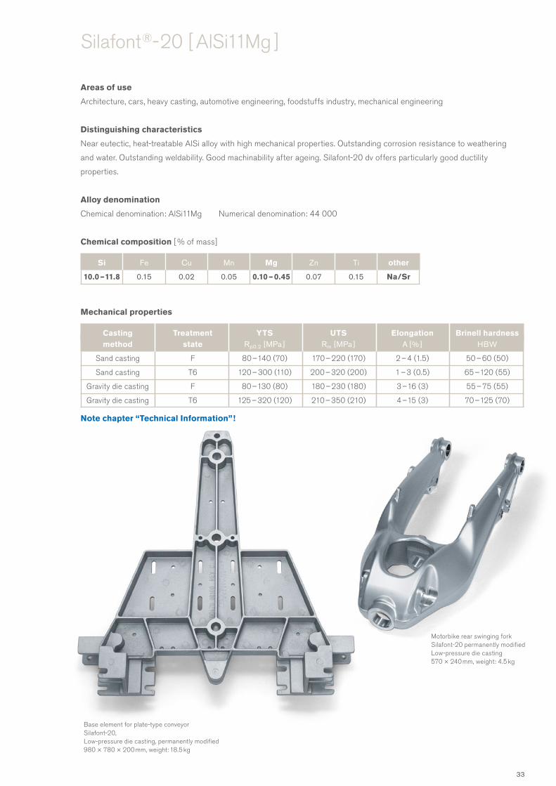
Areas of use
Architecture, cars, heavy casting, automotive engineering, foodstuffs industry, mechanical engineering
Distinguishing characteristics
Near eutectic, heat-treatable AlSi alloy with high mechanical properties. Outstanding corrosion resistance to weathering
and water. Outstanding weldability. Good machinability after ageing. Silafont-20 dv offers particularly good ductility
properties.
Alloy denomination
Chemical denomination: AlSi11Mg Numerical denomination: 44 000
Chemical composition [ % of mass]
Mechanical properties
Silafont ®- 20 [ AlSi11Mg ]
Motorbike rear swinging fork Silafont-20 permanently modified Low-pressure die casting 570 × 240 mm, weight: 4.5 kg
Base element for plate-type conveyor Silafont-20, Low-pressure die casting, permanently modified 980 × 780 × 200 mm, weight: 18.5 kg
Casting Treatment YTS UTS Elongation Brinell hardness method state Rp0.2 [ MPa ] Rm [ MPa ] A [ % ] HBW
Sand casting F 80 – 140 (70) 170 – 220 (170) 2 – 4 (1.5) 50 – 60 (50)
Sand casting T6 120 – 300 (110) 200 – 320 (200) 1 – 3 (0.5) 65 – 120 (55)
Gravity die casting F 80 – 130 (80) 180 – 230 (180) 3 – 16 (3) 55 – 75 (55)
Gravity die casting T6 125 – 320 (120) 210 – 350 (210) 4 – 15 (3) 70 – 125 (70)
Si Fe Cu Mn Mg Zn Ti other
10.0 – 11.8 0.15 0.02 0.05 0.10 – 0.45 0.07 0.15 Na/Sr
Note chapter “Technical Information”!
33

Areas of use
Cars, automotive engineering
Parts which are subjected to high strength loads at high temperatures.
Distinguishing characteristics
Very high ultimate tensile strength, yield tensile strength and hardness values are achieved through full artificial ageing.
Good mechanical properties at higher temperatures. Good machining characteristics. Reduced corrosion resistance.
Good running and sliding properties, wear resistant.
Alloy denomination
Chemical denomination: AlSi12CuNiMg Numerical denomination: 48 000
Chemical composition [ % of mass]
Mechanical properties
Silafont ®- 70 [ AlSi12CuNiMg ]
Housing for screw pumps Silafont-70, artificially aged Sand casting Ø 200 × 700 mm, weight: 12.0 kg
Cylinder housing with cylinder head Silafont-70, artificially aged Gravity die casting 290 × 175 × 170 mm, weight: 5.4 kg
Casting Treatment YTS UTS Elongation Brinell hardness method state Rp0.2 [ MPa ] Rm [ MPa ] A [ % ] HBW
Sand casting F 120 – 170 (110) 130 – 180 (120) 0.5 – 1.5 (0.5) 80 – 90 (80)
Sand casting T6 200 – 300 (190) 220 – 300 (200) 0.3 – 1.0 (0.3) 130 – 160 (130)
Sand casting T5 140 – 190 (140) 160 – 190 (160) 0.2 – 1.0 (0.2) 80 – 90 (80)
Gravity die casting F 190 – 260 (180) 200 – 270 (190) 1.0 – 2.5 (0.5) 90 – 105 (90)
Gravity die casting T6 320 – 390 (280) 350 – 400 (300) 0.5 – 2.0 (0.5) 135 – 160 (135)
Gravity die casting T5 185 – 210 (150) 200 – 230 (180) 0.5 – 2.0 (0.5) 90 – 110 (90)
Si Fe Cu Mn Mg Zn Ti other
11.0 – 13.5 0.15 0.8 – 1.3 0.05 0.9 – 1.3 0.10 0.10 0.8 – 1.3 Ni
Note chapter “Technical Information”!
34

Castaman ®
An alloy family, that use the possibilities of recycling, to a desired
high sustainability – to come represented in carbon footprint
counter.
Nature’s role model: the lupine, growing from the humus of last
year’s crop.
35

Castaman® - 35 [ AlSi10MnMg ]
Areas of use
Large and huge structural car body casts, lighting, automotive engineering, mechanical engineering
Distinguishing characteristics
High pressure die casting alloy with very good casting properties, even with thick-walled designs.
Very good corrosion resistance to weathering and water.
Alloy denomination
Chemical denomination: AlSi10MnMg Numerical denomination: 43 500
Chemical composition [ % of mass]
Mechanical properties
Processing properties compared to other high pressure die casting alloys
Si Fe Cu Mn Mg Zn Ti other
9.5 – 11.0 0.2 0.03 0.5 – 0.8 0.2 – 0.5 0.10 0.15 Sr
Alloy type Castaman-35 Silafont-36 Silafont-09
Sticking tendency low low low
Die life 100 % 100 % 100 %
Linear shrinkage 0.4 – 0.6 % 0.4 – 0.6 % 0.4 – 0.6 %
Note chapter “Technical Information”!
Casting method
Treatment state
YTSRp0.2 [MPa ]
UTSRm [ MPa ]
ElongationA [ % ]
Brinell hardness[ HBW ]
HPDC F 120 – 150 200 – 2720 4 – 9 75 – 90
HPDC T6 180 – 260 250 – 320 6 – 12 80 – 110
36

Castasil ® – large areas, high dimensional stability, fantastic to cast
An alloy, produced for large, high pressure die cast structural parts
in the automotive construction industry. Lamborghini produced the
first series in the Gallardo Spyder. Numerous manufacturers now
recognise the benefits of this alloy: high dimensional stability, can
be used without heat treatment, shapes well and easy to weld.
Nature’s equivalent: the vine branch which turns towards the sun,
flexible, elastic and yet incredibly tough and strong.
37

Areas of use
Connection nodes for space frame designs; thin-walled body parts; architecture, cars, lighting, aircraft, domestic appliances,
air conditioning, automotive engineering, foodstuffs industry, mechanical engineering, shipbuilding, defence engineering;
replaces high pressure die castings with T7 or T6 with air quenching
Distinguishing characteristics
High pressure die casting alloy with excellent castability. Very high elongation in as-cast state as a result of which it can be
used in more ways when in as-cast state. Further increase in ductility thanks to single-stage heat treatment. No distortion or
blisters from solution heat treatment, very good corrosion resistance, no long-term ageing due to heat, good machinability,
ideal for riveting and adhesive bonding in automotive engineering.
Alloy denomination
Chemical denomination: AlSi9MnMoZr
Chemical composition [ % of mass]
Mechanical properties
Castasil ®- 37 [ AlSi9MnMoZr ]
Suspension-strut dome Castasil-37 High pressure die casting, wall thickness: 5 mm, 430 × 330 × 340 mm, weight: 4.4 kg
Upper safety housing for high voltage plug connectors Castasil-37 High pressure die casting 210 × 330 × 140 mm, Gewicht: 1.5 kg
Si Fe Cu Mn Mg Zn Mo Zr other
8.5 – 10.5 0.15 0.05 0.35 – 0.60 0.06 0.07 0.1 – 0.3 0.1 – 0.3 Sr
Casting Treatment Wall thickness YTS UTS Elongation method state Rp0.2 [ MPa ] Rm [ MPa ] A [ % ]
HPDC F 2 – 3 120 – 150 260 – 300 10 – 14
HPDC F 3 – 5 100 – 130 230 – 280 10 – 14
HPDC F 5 – 7 80 – 110 200 – 250 10 – 14
Note chapter “Technical Information”!
38

Castasil ®- 37 [ AlSi9MnMoZr ]
Reinforcement for convertible soft-top Castasil-37 High pressure die casting, weldable 260 × 220 × 60 mm, weight: 0.6 kg
Longitudinal carrier node of aluminium body Castasil-37 High pressure die casting, weldable 320 × 210 × 200 mm, weight: 2.0 kg
Convertible soft-top lever Castasil-37 High pressure die casting 510 × 100 × 80 mm, weight: 0.56 kg
Internal door parts for a sports car Castasil-37 High pressure die casting 620 × 340 × 170 mm, weight: 1.2 kg 700 × 340 × 170 mm, weight: 2.1 kg
Longitudinal carrier Audi A8 Castasil-37 High pressure die casting 1400 × 600 × 300 mm, weight: 10 kg
39

Areas of use
Also for huge castings with requirements in terms of high thermal or electrical conductivity.
Conductor plate for electronics, automotive and mechanical engineering, LED-lighting, air cooling
Distinguishing characteristics
High pressure die casting alloy with high casting ability, optimized for high thermal or electrical
conductivity. A casting treatment O gives highest conductivity compared with other AlSi-die casting alloys.
Flangeable, very good corrosion resistance to weather.
Alloy denomination
Chemical denomination: AlSi9Sr
Chemical composition [ % of mass]
Mechanical properties
Castasil ®- 21 [ AlSi9Sr ]
Heatsink for electronic deviceCastasil-21, State OHigh pressure die casting170 x 70 x 70 mm; weight: 0.4 kg
Casting Treatment YTS UTS Elongation Brinell hardness method state Rp0.2 [ MPa ] Rm [ MPa ] A [ % ] HBW
HPDC F 90 – 100 200 – 230 6 – 9 60 – 70
HPDC O 80 – 90 170 – 190 9 – 14 55 – 65
Si Fe Cu Mn Mg Zn Ti other
8.0 – 9.0 0.5 – 0.7 0.02 0.01 0.03 0.07 0.01 Sr
Note chapter “Technical Information”!
40

Unifont ® – high strength and regenerative power
Unifont alloys offer high strength without heat treatment and
outstanding casting properties, but limited shaping properties.
They are used for components which are often large and difficult,
especially in circumstances which require high strength levels: in
mechanical engineering, domestic appliances and medical tech-
nology. Thanks to their self-hardening character, they regenerate
themselves after overloads.
Nature’s role model: the water lily which closes its petals for pro-
tection at night and only opens them again when the sun rises.
41

Areas of use
Heavy casting, mechanical engineering, pattern and mould construction, optics, furniture, textile industry, hydraulic cast,
domestic appliances, defence engineering
Distinguishing characteristics
Self-ageing alloy with very good strength and elongation properties, especially in low-pressure gravity die casting.
Very good mechanical polishability and machinability. Good weldability. Aged again following e. g. thermal loading from
welding. Casting properties similar to Silafont-30.
Alloy denomination
Chemical denomination: AlZn10Si8Mg Numerical denomination: 71 100
Chemical composition [ % of mass]
Mechanical properties
Unifont ®- 90 [ AlZn10Si8Mg ]
Base plate for film cutting equipment Unifont-90 Sand casting, electrically conductive, hard anodised 500 × 500 × 170 mm, weight: 4.8 kg
Casting Treatment YTS UTS Elongation Brinell hardness method state Rp0.2 [ MPa ] Rm [ MPa ] A [ % ] HB
Sand casting T1 190 – 230 (170) 220 – 250 (180) 1 – 2 (1) 90 – 100 (90)
Gravity die casting T1 220 – 250 (220) 280 – 320 (230) 1 – 4 (1) 100 – 120 (95)
Si Fe Cu Mn Mg Zn Ti other
8.5 – 9.5 0.15 0.03 0.10 0.3 – 0.5 9.0 – 10.0 0.15 (Na/Sr)
Note chapter “Technical Information”!
42

Unifont ®- 90 [ AlZn10Si8Mg ]
Weft holder Unifont-90 Gravity die casting 320 × 70 × 55 mm, weight: 0.5 kg
Robot carriage Unifont-90 Sand casting 980 × 250 × 150 mm, weight: 19.5 kg
Door sheet metal template Unifont-90a Sand casting as finished casting1400 × 900 × 900 mm, weight: 70 kg
43

Areas of use
Cars, automotive engineering, mechanical engineering, optics, furniture
Distinguishing characteristics
Self-ageing high pressure die casting alloy for high pressure die casting with high compression strength,
but not with static tensile strength.
Alloy denomination
Chemical denomination: AlZn10Si8Mg
Chemical composition [ % of mass]
Mechanical properties
Unifont ®- 94 [ AlZn10Si8Mg ]
Table bracket for seats in aircraft Unifont-94 High pressure die casting, painted 310 × 65 × 18 mm, weight: 0.16 kgBearing cores for vibration damper
Unifont-94 High pressure die casting, rubber-metal compound Ø 45 – 80 mm, height: 40 – 123 mm, weight: 78 – 450 g
Si Fe Cu Mn Mg Zn Ti
8.5 – 9.5 0.4 0.03 0.4 0.3 – 0.5 9.0 – 10.0 0.10
Casting Treatment YTS UTS Elongation Brinell hardness method state Rp0.2 [ MPa ] Rm [ MPa ] A [ % ] HBW
HPDC T1 230 – 280 300 – 350 1 – 4 105 – 120
Note chapter “Technical Information”!
44

Castadur ® – the power of regeneration
A self-hardening material of high formability which gains strength
without losing its ability to stretch. And even if it loses its proper-
ties, from overheating for example, they return. Castadur’s softly
radiant surface is easy to polish, making it popular for everyday
objects such as furniture.
The material’s homogeneity and silent power are reminiscent of
desert sand dunes, which shaped by the wind are always taking
on new shapes while remaining the same.
45

Areas of use
Architecture, cars, lighting, domestic appliances, automotive engineering, art casts, pattern and mould construction,
optics and furniture
Distinguishing characteristics
Self-ageing alloy for sand and gravity die casting. High strength and elongation, good castability.
Perfectly suited to decorative and technical anodising.
Alloy denomination
Chemical denomination: AlZn3Mg3Cr
Chemical composition [ % of mass]
Mechanical properties
Please refer to the ageing diagram on page 102.
Castadur ®- 30 [ AlZn3Mg3Cr ]
Cast node for glass dome design Castadur-30 Gravity die casting Ø 260 × 110 mm, weight: 2.3 kg
Casting Treatment YTS UTS Elongation Brinell hardness method state Rp0.2 [ MPa ] Rm [ MPa ] A [ % ] HBW
Gravity die casting T1 140 – 160 260 – 290 10 – 20 75 – 85
Note chapter “Technical Information”!
Si Fe Cu Mn Mg Cr Zn Ti Be
0.15 0.15 0.05 0.10 – 0.2 2.5 – 3.0 0.25 – 0.35 2.2 – 2.8 0.03 – 0.15 0.004
46
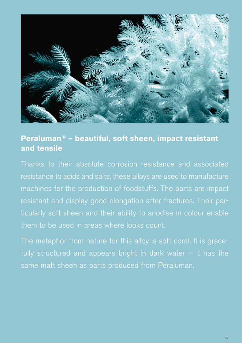
Peraluman ® – beautiful, soft sheen, impact resistant and tensile
Thanks to their absolute corrosion resistance and associated
resistance to acids and salts, these alloys are used to manufacture
machines for the production of foodstuffs. The parts are impact
resistant and display good elongation after fractures. Their par-
ticularly soft sheen and their ability to anodise in colour enable
them to be used in areas where looks count.
The metaphor from nature for this alloy is soft coral. It is grace-
fully structured and appears bright in dark water – it has the
same matt sheen as parts produced from Peraluman.
47

Areas of use
Architecture, fittings, builder’s hardware, lighting, domestic appliances, air conditioning, art casting, foodstuffs industry,
mechanical engineering, pattern and mould construction, optics and furniture, shipbuilding, chemical industry
Distinguishing characteristics
Excellent chemical resistance, particularly to salt water. Perfectly suited to decorative anodic oxidation, outstanding sheen after
mechanical polishing. Very good elongation and impact toughness values. This alloy requires high-quality casting technique.
Alloy denomination
Chemical denomination: AlMg3 Numerical denomination: 51 100
Chemical composition [ % of mass]
Mechanical properties
Peraluman ®- 30 [ AlMg3 ]
Support cylinder for food processing Peraluman-30 Gravity die casting, decoratively anodised Ø 220 × 330 mm, weight: 3.5 kg
Door handle Peraluman-30 Gravity die casting, decoratively anodised 135 × 65 × 15 mm, weight: 140 g
Casting Treatment YTS UTS Elongation Brinell hardness method state Rp0.2 [ MPa ] Rm [ MPa ] A [ % ] HBW
Sand casting F 70 – 100 (60) 170 – 190 (140) 4 – 8 (4) 50 – 60 (45)
Sand casting T6 140 – 160 (110) 200 – 240 (160) 6 – 8 (5) 65 – 75 (60)
Gravity die casting F 70 – 100 (70) 170 – 210 (150) 9 – 16 (6) 50 – 60 (50)
Gravity die casting T6 140 – 160 (110) 240 – 260 (180) 15 – 20 (12) 70 – 80 (70)
Si Fe Cu Mn Mg Zn Ti other
0.45 0.15 0.02 0.01 – 0.4 2.7 – 3.5 0.10 0.01 – 0.15 Be
Note chapter “Technical Information”!
48

Areas of use
Architecture, fittings, builder’s hardware, lighting, domestic appliances, air conditioning, art casting, foodstuffs industry,
optics and furniture, shipbuilding, chemical industry
Distinguishing characteristics
Excellent chemical resistance, particularly to salt water. Perfectly suited to decorative anodic oxidation, outstanding sheen
after mechanical polishing. Very good elongation and impact toughness values. This alloy requires high-quality casting technique.
Alloy denomination
Chemical denomination: AlMg5 Numerical denomination: 51 300
Zusammensetzung [ Masse-% ]
Mechanical properties
Peraluman ®- 50 [ AlMg5 ]
Cooling half-shell for X-ray devices Peraluman-50 Sand casting 640 × 440 × 170 mm, weight: 19 kg
Input housing for autopilot on offshore yachts Peraluman-50 Sand casting, anodically oxidised 290 × 210 × 40 mm, weight: 0.4 kg
Si Fe Cu Mn Mg Zn Ti other
0.30 0.15 0.02 0.01 – 0.4 4.8 – 5.5 0.10 0.01 – 0.15 Be
Casting Treatment YTS UTS Elongation Brinell hardness method state Rp0.2 [ MPa ] Rm [ MPa ] A [ % ] HBW
Sand casting F 100 – 120 (90) 190 – 250 (170) 10 – 15 (8) 55 – 70 (50)
Gravity die casting F 100 – 140 (100) 200 – 260 (180) 10 – 25 (8) 60 – 75 (55)
Note chapter “Technical Information”!
49

Areas of use
Architecture, fittings, lighting, domestic appliances, air conditioning, art casting, foodstuffs industry, mechanical engineering,
optics/furniture, shipbuilding, chemical industry
Distinguishing characteristics
Heat-treatable alloy with average mechanical properties and high elongation.
Outstanding corrosion resistance, very good sheen after mechanical polishing.
Excellent machinability. This alloy requires high-quality casting technique.
Alloy denomination
Chemical denomination: AlMg5Si Numerical denomination: 51 400
Chemical composition [ % of mass]
Mechanical properties
Peraluman ®- 56 [ AlMg5Si ]
Stator for centrifugal pump Peraluman-56 Sand casting Ø 245 × 50 mm, weight: 0.95 kg
Pump housing Peraluman-56 Sand casting Ø 390 × 115 mm, weight: 9.2 kg
Si Fe Cu Mn Mg Zn Ti other
0.9 – 1.3 0.15 0.02 0.01 – 0.4 4.8 – 5.5 0.10 0.01 – 0.15 Be
Casting Treatment YTS UTS Elongation Brinell hardness method state Rp0.2 [ MPa ] Rm [ MPa ] A [ % ] HBW
Sand casting F 110 – 130 (100) 160 – 200 (140) 3 – 4 (2) 60 – 80 (55)
Sand casting T6 110 – 160 (110) 180 – 220 (160) 3 – 4 (2) 70 – 80 (65)
Gravity die casting F 110 – 150 (100) 180 – 240 (150) 3 – 5 (3) 65 – 85 (60)
Gravity die casting T6 110 – 160 (110) 210 – 260 (200) 3 – 18 (5) 75 – 85 (70)
Note chapter “Technical Information”!
50

Magsimal ® – of filigree lightness, but extremely resilient
An alloy for delicate parts which need to retain their strength
and precise form over a long period. Good weldability, high resil-
ience, can be used in virtually any application. Maximum corro-
sion resistance, even to salt water.
Parts which simulate the structure of the wings of a dragonfly:
wafer thin, elastic and yet offering maximum strength and resil-
ience, they enable this dainty insect to fly distances that never
cease to amaze.
51

Areas of use
Architecture, cars, aircraft, domestic appliances, air conditioning, automotive engineering, foodstuffs industry,
mechanical engineering, optics and furniture, shipbuilding, chemical industry
Distinguishing characteristics
High pressure die casting alloy with excellent mechanical and dynamic properties with thin walls.
Very good weldability, suited to stamp riveting. Very good corrosion resistance, excellent mechanical polishability
and good machinability, ideal adhesive bonding in car body design.
Alloy denomination
Chemical denomination: AlMg5Si2Mn Numerical denomination: 51 500
Chemical composition [ % of mass]
Mechanical properties
Magsimal ®- 59 [ AlMg5Si2Mn ]
Strut mounting for sports car Magsimal-59, as-cast state High pressure die casting, wall thickness 3 mm 590 × 450 × 340 mm, weight: 3.0 kg
Oil pan Magsimal-59, as-cast state High pressure die casting, wall thickness 2.2 mm 440 × 310 × 180 mm, weight: 3.0 kg
Si Fe Cu Mn Mg Zn Ti Be
1.8 – 2.6 0.20 0.03 0.5 – 0.8 5.0 – 6.0 0.07 0.20 0.004
Casting Treatment Wall thickness YTS UTS Elongation method state Rp0.2 [ MPa ] Rm [ MPa ] A [ % ]
HPDC F < 2 > 220 > 300 10 – 15
HPDC F 2 – 4 160 – 220 310 – 340 12 – 18
HPDC F 4 – 6 140 – 170 250 – 320 9 – 14
HPDC F 6 – 12 120 – 145 220 – 260 8 – 12
Note chapter “Technical Information”!
52

Magsimal ®- 59 [ AlMg5Si2Mn ]
Internal door parts for off-road vehicleMagsimal-59, as-cast state High pressure die casting, suited to welding, wall thickness 1.8 – 2.0 mm up to 1400 mm, weight: 2.2 kg
Internal door part for vehicle Magsimal-59, as-cast stateHigh pressure die casting, suited to welding610 x 250 x 100 mm, Gewicht: 1.0 kg
Door design for four-door sports car Magsimal-59, as-cast state High pressure die casting, wall thickness 2 mm 1140 × 690 × 155 mm, weight: 4.1 kg
Node for window frame Magsimal-59, as-cast state High pressure die casting, weldable Up to 510 mm long, weight: 0.20 – 0.35 kg
Rear cross member Magsimal-59, as-cast state High pressure die casting, wall thickness 4 mm 1080 × 370 × 150 mm, weight: 6.5 kg
53
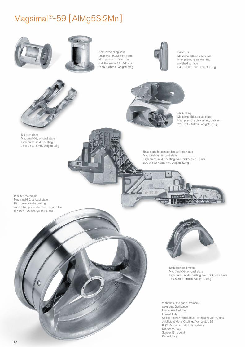
Magsimal ®- 59 [ AlMg5Si2Mn ]
Endcover Magsimal-59, as-cast state High pressure die casting, polished surface 34 × 15 × 13 mm, weight: 6.0 g
Ski boot clasp Magsimal-59, as-cast state High pressure die casting 76 × 23 × 18 mm, weight: 20 g
Rim, MZ motorbike Magsimal-59, as-cast state High pressure die casting, cast in two parts, electron beam welded Ø 460 × 180 mm, weight: 6.4 kg
With thanks to our customers:ae-group, GerstungenDruckguss Hof, HofFormal, ItalyGeorg Fischer Automotive, Herzogenburg, AustriaJVM Light Metal Castings, Worcester, GBKSM Castings GmbH, HildesheimMicrotech, ItalySander, EnnepetalCervati, Italy
Belt retractor spindle Magsimal-59, as-cast state High pressure die casting, wall thickness 1.0 – 5.0 mm Ø 56 × 55 mm, weight: 66 g
Stabiliser rod bracket Magsimal-59, as-cast state High pressure die casting, wall thickness 3 mm 130 × 85 × 45 mm, weight: 0.2 kg
Base plate for convertible soft-top hinge Magsimal-59, as-cast state High pressure die casting, wall thickness 2 – 5 mm 600 × 350 × 280 mm, weight: 3.2 kg
Ski binding Magsimal-59, as-cast state High pressure die casting, polished 77 × 69 × 53 mm, weight: 150 g
54

Aluman ® – resistant even at very high temperatures
The alloy with the highest melting point of all aluminium alloys.
Its good thermal conductivity makes the alloy perfectly suited to
the manufacture of cast parts such as heat exchangers.
Aluman parts display a high solidification temperature which
means that they remain solid when surrounding aluminium
alloys are liquid. A workpiece cast from Aluman can therefore
be soldered with an eutectic AlSi alloy.
Its counterpart in nature is fresh water icebergs which float in
the salt water of polar seas as they don’t share the same melting
point.
55

Areas of use
Cars, air conditioning, automotive engineering, mechanical engineering
Distinguishing characteristics
Casting alloy which can be hard soldered. Designed for High pressure die casting,
but also usable as sand and gravity die casting alloy.
Alloy denomination
Chemical denomination: AlMn1.6
Chemical composition [ % of mass]
Mechanical properties
Aluman ®- 16 [ AlMn1.6 ]
Collector box for oil radiator Aluman-16 High pressure die casting 77 × 40 × 55 mm, weight: max. 0.13 kg
Radiator pipe connection Aluman-16 Sand castingMax. 70 × 60 × 45 mm, weight: 0.3 kg
Base plate for electronic device, assembled due hard soldering Aluman-16 Sand casting230 × 160 × 15 mm, weight: 0.9 kg
Si Fe Cu Mn Mg Zn Ti
0.15 0.20 – 0.90 0.03 1.4 – 1.6 0.05 0.10 0.15
Casting Treatment YTS UTS Elongation Brinell hardness method state Rp0.2 [ MPa ] Rm [ MPa ] A [ % ] HBW
HPDC F 90 – 120 160 – 180 8 – 15 40 – 60
Sand casting F 80 – 100 130 – 160 4 – 8 40 – 50
Note chapter “Technical Information”!
56

Alufont ® – the ultimate strength for lightweight
construction
This alloy’s outstanding mechanical properties make it a serious
alternative to steel. It is easy to weld and excellent to machine,
and it can be used wherever parts are subject to high force and
load levels. Its low weight also makes it ideal for elements that
have to be moved: in motorsport, in machines or for example as
a hinged element for telescopic lifting platforms.
As with crystals, these alloys have the structure of their joints to
thank for their strength.
57

Areas of use
All kinds of highly loaded parts where corrosion properties are no obstacle.
Cars, automotive engineering, manufacture of engines, mechanical engineering, textile industry, defence engineering
Distinguishing characteristics
High-strength alloy for partial and artificial ageing. Outstanding machinability, very good polishing properties, good
weldability, limited corrosion resistance. Mechanical values may be greatly varied by modifying artificial ageing.
Alloy denomination
Chemical denomination: AlCu4Ti Numerical denomination: 21 100
Chemical composition [ % of mass]
Mechanical properties
Alufont ®- 52 [ AlCu4Ti ]
Clamp element Alufont-52, artificially aged Gravity die casting 70 × 70 × 30 mm, weight: 0.1 kg
Wheelset bearing housing for rail vehicle Alufont-52, artificially aged Sand casting 920 × 840 × 330 mm, weight: 62 kg
Si Fe Cu Mn Mg Zn Ti
0.15 0.15 4.2 – 5.2 0.01 – 0.5 0.03 0.07 0.15 – 0.25
Casting Treatment YTS UTS Elongation Brinell hardness method state Rp0.2 [ MPa ] Rm [ MPa ] A [ % ] HBW
Sand casting T64 210 – 240 (180) 300 – 360 (260) 8 – 15 (4) 90 – 100 (90)
Sand casting T6 300 – 420 (280) 400 – 475 (350) 3 – 4 (2) 125 – 145 (120)
Gravity die casting T64 210 – 250 (190) 360 – 400 (300) 12 – 20 (10) 90 – 120 (90)
Gravity die casting T6 310 – 400 (300) 420 – 475 (400) 7 – 16 (4) 130 – 145 (130)
Note chapter “Technical Information”!
58

Alufont ®- 52 [ AlCu4Ti ]
Tool holder Alufont-52, artificially aged Sand casting 680 × 390 × 200 mm, weight: 35 kg
ICE II gearbox housing Alufont-52, artificially aged Sand casting 1800 × 850 × 250 mm, weight: 175 kg
Mechanism for robot arm Alufont-52, artificially aged Sand casting 190 × 60 × 20 mm, weight: 0.14 kg
59

Areas of use
Cars, automotive engineering, manufacture of engines, mechanical engineering, defence engineering
Distinguishing characteristics
Aluminium casting alloy with maximum ultimate tensile strength, yield tensile strength and hardness values,
combined with outstanding elongation. Values may be varied greatly by modifying artificial ageing.
Outstanding machinability, very good polishing properties, good weldability.
Alloy denomination
Chemical denomination: AlCu4TiMgAg
Chemical composition [ % of mass]
Mechanical properties
Alufont ®- 48 [ AlCu4TiMgAg ]
Star-shaped flange for rail vehiclesAlufont-48, artificially aged Sand casting Ø 700 × 100 mm, weight: 38 kg
Si Fe Cu Mn Mg Zn Ti other
0.05 0.10 4.0 – 5.0 0.01 – 0.5 0.15 – 0.35 0.05 0.15 – 0.35 0.4 – 1.0 Ag
Casting Treatment YTS UTS Elongation Brinell hardness method state Rp0.2 [ MPa ] Rm [ MPa ] A [ % ] HBW
Sand casting T64 200 – 270 (180) 370 – 430 (320) 14 – 18 (7) 105 – 120 (100)
Sand casting T6 410 – 450 (320) 460 – 510 (380) 3 – 7 (2) 130 – 150 (125)
Gravity die casting T6 410 – 460 (340) 460 – 510 (440) 5 – 8 (3) 130 – 150 (130)
Note chapter “Technical Information”!
60

Thermodur ® – a glimpse into the future
A new material that withstands high temperatures like never before,
allowing it play a key role in increased efficiency in combustion
engines: increased output, lower fuel consumption, greater durability
and lower emissions.
This alloy simulates the spider’s silk: outstanding mechanical prop-
erties, maximum strength, stable, resilient and incredibly light.
61

Areas of use
Manufacture of engines, crankcases, engine components
Distinguishing characteristics
High pressure die casting alloy for the manufacture of engines for parts that require very good mechanical properties
at elevated temperatures and high corrosion resistance.
Alloy denomination
Chemical denomination: AlMg7Si3Mn
Chemical composition [ % of mass]
Mechanical properties
Thermodur ®- 72 [ AlMg7Si3Mn ]
Example of possible use: four-cylinder engine block, looking at bearing blocks
Si Fe Cu Mn Mg Zn Ti other
2.8 – 3.2 0.15 0.03 0.5 – 0.8 7.0 – 8.8 0.07 0.15 0.004 Be
Ageing Ageing YTS UTS Elongation Brinell hardness temperature time Rp0.2 [ MPa ] Rm [ MPa ] A [ % ] HBW
20 °C 190 – 220 350 – 380 7 – 10 80 – 100
150 °C 500 h 220 – 245 260 – 290 > 15
225 °C 500 h 150 – 175 180 – 205 > 20
Tested at temperature indicatedNote chapter “Technical Information”!
62

Thermodur ®- 73 [ AlSi11Cu2Ni2Mg2Mn ]
Areas of use
Cars, manufacture of engines
Distinguishing characteristics
Very good hardness and high strength in as-cast state, very good mechanical properties at elevated temperatures.
Good castability for sand, chill and high pressure die casting. Very good wear resistance. Excellent weldability and
machinability.
Alloy denomination
Chemical denomination: AlSi11Cu2Ni2Mg2Mn
Chemical composition [ % of mass]
Mechanical properties
Ventilator hubThermodur-73, as-cast stateHigh pressure die casting with steel insertØ 305 x 43 mm; weight: 5.9 kg
Si Fe Cu Mn Mg Zn Ti other
10.0 – 11.8 0.15 1.8 – 2.3 0.4 1.8 – 2.3 0.10 0.10 1.8 – 2.3 Ni; Sr
Ageing Ageing YTS UTS Elongation Brinell hardness temperature time Rp0.2 [ MPa ] Rm [ MPa ] A [ % ] HBW
20 °C 270 – 300 300 – 320 < 1 130 – 150
150 °C 500 h 280 – 310 330 – 355 < 1
225 °C 500 h 130 – 155 250 – 280 1– 2
Note chapter “Technical Information”! Tested at temperature indicated
63

1 Einschmelzen der Masseln
2 Salzbehandlung
3 Magnesiumabbrand
4 Abkrätzen
5 Temperatur nach dem
Einschmelzen
6 Temperatur im Warmhalteofen
7 Entgasen und Reinigen
der Schmelze
8 Abkrätzen
9 Kornfeinen
10 Veredelung
11 Gießtemperatur ( Richtwerte )
12 Gießkammer- oder
-werkzeug-Temperatur
13 Abschrecken der Gussstücke
nach dem Entformen
14 Wärmebehandlung
Magsimal ®- 59 [ AlMg5Si2Mn ]
Arbeitsfolge bei der Herstellung von Druckgussstücken aus Magsimal®-59
möglichst zügig in leistungsfähigen Öfen, damit Mg-Abbrand, Gasaufnahme und
Oxidation der Schmelze gering bleiben; nachsetzen von vorgewärmten Masseln und
grobstückigem Kreislaufmaterial in kleinen Mengen, sonst Seigerungen möglich;
Feuerfestmassen mit hohem Tonerdeanteil oder dichte Stampfmassen verwenden;
Phosphor- und Natrium-Aufnahme vermeiden!
Übliches Schmelzhilfssalzen verboten ! Es besteht die Gefahr der Na-Aufnahme.
normalerweise Abbrand von 0,1 % je Schmelzung, üblicherweise keine Korrektur
notwendig; bei einem Mg-Gehalt erheblich unter 5,0 % Zugabe von bis zu 0,5 %
Reinmagnesium möglich
nach dem Einschmelzen erforderlich
maximal 780 °C ( Temperatur kontrollieren ! )
nicht unter 650 °C sinken lassen und für Schmelzebewegung sorgen durch:
• Wärmekonvektion
• Rotor ( Impeller )
• Spülgaseinleitung am besten über Bodensteine
• Schmelze-Nachfüllung
keine tiefen Öfen mit Deckenheizung bei ruhender Schmelze verwenden !
Feuerfestmassen mit hohem Tonerdeanteil oder infiltrationssicherem Aufbau
verwenden !
• wirkungsvolle Reinigung und schnellste Methode mit schnell laufendem Rotor zur
Gaseinleitung, 7 – 10 l/min Argon oder Stickstoff, 6 – 10 min
• Spüllanze mit feinporösem Kopf, benötigt längere Behandlungszeiten ( Abkühlung ! )
• Spülgastabletten erreichen nicht die erforderliche Wirkung !
sorgfältiges Abkrätzen erforderlich
Um den Metallgehalt der Krätze zu verringern, dürfen nur ausgesprochen Na-freie
Salze verwendet werden !
verboten ! TiB 2 Kornfeiner vergröbert das Eutektikum
verboten ! Die erreichbare Dehnung würde erheblich gesenkt werden.
690 – 730 °C, variiert je nach Gestalt, Größe und Wanddicke der Druckgussstücke
um 200 °C anwärmen; beheizte Gießkammer > 250 °C
Sofortiges Abschrecken in Wasser senkt die Dehngrenze und steigert die Dehnung.
Normalerweise keine
4 Zeilen zuviel Text
73
Anticorodal ® - 70 [ AlSi7Mg0,3 ]Arbeitsfolge bei der Herstellung von Gussstücken aus Anticorodal-70
1 Einschmelzen der Masseln
2 Salzbehandlung
3 Magnesiumabbrand
4 Abkrätzen
5 Temperatur nach dem Einschmelzen
6 Entgasen und Reinigen der Schmelze
7 Abkrätzen und Kornfeinen
8 Veredelung mit Sr
Sandguss mit Na
Kokillenguss mit Na
9 Reinigen und Abkrätzen
10 Gießtemperatur ( Richtwerte )
unveredelt
mit Dauerveredelung
11 Kokillentemperatur
12 Lösungsglühen
13 Abkühlen von Lösungsglühtemperatur
14 Zwischenlagerzeit vor dem
Warmauslagern
15 Teilaushärtung T64
16 Vollaushärtung T6
17 Stabilisierungsglühung
möglichst rasch in leistungsstarken Öfen, damit Mg-Abbrand, Gasaufnahme und
Oxidation der Schmelze gering bleiben; nachsetzen von vorgewärmten Masseln und
Kreislaufmaterial in kleinen Mengen, sonst Seigerungen und Oxideinschlüsse
beim Schmelzen nicht nötig
normalerweise Abbrand von 0,05 Masse- % je Schmelzung; ist zu kompensieren, wenn
der Mg-Gehalt der Schmelze von Anticorodal-70 / -70 dv unter 0,25 % liegt; kann mit
AlMg-Vor- oder Gusslegierung oder Reinmagnesium zulegiert werden
nach dem Einschmelzen erforderlich
maximal 780 °C ( Temperatur kontrollieren ! )
• wirkungsvolle Reinigung und schnellste Methode mit schnell laufendem Rotor zur
Gaseinleitung, 7 – 10 l/min Argon oder Stickstoff, 6 – 10 min
• Spüllanze mit feinporösem Kopf benötigt längere Behandlungszeiten ( Abkühlung ! )
• Stickstoff abgebende Spülgastablette mit 150 – 350 l Stickstoff/kg ( Tauchglocken-
verfahren )
kornfeinen am wirkungsvollsten für Anticorodal-70 mit körnigem Gefüge: nach dem
sorgfältigen Abkrätzen kornfeinen mit TiB-Vorlegierung oder Salztabletten auf Korn-
feinungszahlen KF ≥ 9, d. h. Kornfläche kleiner als 2,5 mm2
bei Verwendung von dauerveredelten Masseln insbesondere, wenn Strontium-Gehalt
unter 0,015 % gesunken ist; zu veredeln mit AlSr-Vorlegierung, die vorzugsweise nur
5 % Strontium enthält
• mit 0,03 – 0,04 vakuumverpacktem Natrium oder 0,2 – 0,3 exothermen Veredelungs-
tabletten oder 0,05 – 0,2 Salz-Granulat ( Angaben in % des Einsatzgewichtes )
• dickwandiger Kokillenguss und Kokillenguss mit Sandkernen: mit 0,015 – 0,025
vakuumverpacktem Natrium oder 0,1 – 0,2 exothermen Veredelungstabletten oder
0,05 – 0,2 Salz-Granulat ( Angaben in % des Einsatzgewichtes )
Dünnwandiger Kokillenguss wird nur in seltenen Fällen mit Na veredelt.
Gasbehandlung mit Rotor bevorzugen, z. B. durch integrierte Schmelzebehandlung bei
gleichzeitiger Zugabe von Na-Salz-Granulat und Gasreinigung
abhängig von Gestalt, Größe und Wanddicke des Gussstückes
720 – 760 °C
740 – 780 °C
300 – 400 °C je nach Gussstück
520 – 535 °C für 6 – 10 Stunden; für Sonderbauteile: 535 – 545 °C / 24 Stunden
( Die angegebenen Glüh- und Auslagerzeiten gelten ohne Aufheizdauer. )
möglichst ohne Verzögerung in Wasser ( 10 – 40 °C )
nur wenn Richtarbeit notwendig, maximal 12 Stunden
150 – 160 °C / 2 – 3 Stunden für hohe Dehnung
155 – 165 °C / 6 – 8 Stunden für hohe Festigkeit
erforderlich für Gussstücke mit Wärmebelastung: 210 – 230 °C / 6 – 8 Stunden,
anschließend Luftabkühlung auf Raumtemperatur
67
1 Einschmelzen der Masseln
2 Salzbehandlung
3 Magnesiumabbrand
4 Strontiumabbrand
5 Abkrätzen
6 Temperatur
7 Entgasen und Reinigen der Schmelze
8 Abkrätzen
9 Gießtemperatur ( Richtwerte )
10 Formtemperatur
11 Aushärtung durch T5
12 Lösungsglühen
13 Abkühlen von Lösungsglühtemperatur 14 Zwischenlagerzeit vor dem Warmauslagern
15 Vollaushärtung T6
16 Überalterung T7
Silafont ®- 36 [ AlSi10MnMg ]Arbeitsfolge bei der Herstellung von Druckgussstücken aus Silafont-36
möglichst rasch in leistungsfähigen Öfen, damit Magnesium-Abbrand, Gasaufnahme
und Oxidation der Schmelze gering bleiben; nachsetzen von vorgewärmten Masseln
und Kreislaufmaterial in kleinen Mengen, sonst Seigerungen und Oxideinschlüsse;
Kreislaufanteil kann bis 50 % betragenbeim Schmelzen nicht nötignormalerweise Abbrand von 0,03 % je Schmelzung; ist nur zu kompensieren, wenn
der Magnesium-Gehalt der Schmelze außerhalb der Toleranz liegt, mit Magnesium-
Vorlegierung oder Reinmagnesiumüblicherweise Abbrand von 30 – 50 ppm je Schmelzung; Sr ist nur aufzulegieren,
wenn der Gehalt in der Schmelze unterhalb von 80 ppm liegt, mit AlSr5 oder AlSr10.
Bei erstmaligem Aufschmelzen in einem neuen Tiegel oder einem Tiegel, der
bisher nicht für Sr-veredelte Legierungen verwendet wurde, fällt der Sr-Gehalt stark
ab. Dabei diffundiert Strontium in den Tiegel, eine Sättigung ist nach erstem Auf-
schmelzen erreicht.
nach dem Einschmelzen erforderlichnach dem Einschmelzen maximal 780 °C ( Temperatur kontrollieren ! )
• im Transporttiegel, besser im Warmhaltetiegel, -gefäß oder im Dosierofen mit
Bodensteinen; wirkungsvolle Reinigung und schnellste Methode mit schnell
laufendem Rotor zur Gaseinleitung, 7 – 10 l/min Argon oder Stickstoff, 6 – 10 min
• Spüllanze mit feinporösem Kopf, benötigt längere Behandlungszeiten ( Abkühlung ! )
• Stickstoff abgebende Spülgastabletten im Tauchglockenverfahren sind wenig geeignet.
nach dem Entgasen erforderlich; der Metallgehalt der Krätze kann durch die Zugabe
von Schmelzhilfssalzen bei oder nach der Impellerbehandlung reduziert werden
680 – 710 °C – abhängig von Gestalt, Fließweg und Wanddicke des Druckguss-
stückes, aber auch von Fließrinnenlänge des Dosierofens und von evtl. Kammerheizung
200 – 250 °C je nach Gussstück Wasserabschrecken direkt nach der Gussentnahme, möglichst hohe Temperatur
( dann auslagern wie 15/16 )480 – 490 °C / 2 – 3 Stunden für Sonderbauteile möglich: Absenkung bis 400 °C / 0,5 Stunden
möglichst ohne Verzögerung in Wasser ( 10 – 40 °C ); bei Abkühlung an Luft erreicht
man nur eine erheblich geringere Dehngrenzenur wenn Richtarbeit notwendig, üblicherweise maximal 12 Stunden155 – 170 °C / 2 – 3 Stunden 190 – 230 °C / 2 – 3 StundenDie angegebenen Glüh- und Auslagerungszeiten gelten ohne Aufheizdauer.
68
1 Einschmelzen der Masseln
2 Salzbehandlung 3 Magnesiumabbrand
4 Abkrätzen 5 Temperatur nach dem
Einschmelzen 6 Entgasen und Reinigen
der Schmelze
7 Abkrätzen und Kornfeinen
8 Veredelung mit Sr
Sandguss mit Na
Kokillenguss mit Na
9 Reinigen und Abkrätzen 10 Gießtemperatur ( Richtwerte )
Sandguss
Kokillenguss 11 Kokillentemperatur 12 Wärmebehandlung
Unifont ®- 90 [ AlZn10Si8Mg ]
Arbeitsfolge bei der Herstellung von Gussstücken aus Unifont ®-90 möglichst rasch in leistungsfähigen Öfen, damit Mg-Abbrand, Gasaufnahme und
Oxidation der Schmelze gering bleiben; nachsetzen von vorgewärmten Masseln und
Kreislaufmaterial in kleinen Mengen; auch eine nur geringe Cu-Verunreinigung der
Schmelzezusammensetzung vermeiden !
beim Schmelzen nicht nötignormalerweise Abbrand von 0,05 % je Schmelzung; ist zu kompensieren, wenn
Gesamtmagnesium-Gehalt unter 0,25 % sinkt durch Zugabe von Mg-Vorlegierung
oder Reinmagnesium.nach dem Einschmelzen erforderlich
maximal 780 °C ( Temperatur kontrollieren ! )• wirkungsvolle Reinigung und schnellste Methode mit schnell laufendem Rotor zur
Gaseinleitung, 7 – 10 l/min Argon oder Stickstoff, 6 – 10 min
• Spüllanze mit feinporösem Kopf, benötigt längere Behandlungszeiten ( Abkühlung ! )
• Stickstoff abgebende Spülgastablette mit 150 – 350 l Stickstoff/kg ( Tauch-
glockenverfahren )kornfeinen am wirkungsvollsten für Unifont-90 mit körnigem Gefüge; bei hohem
Kreislaufanteil: nach dem Abkrätzen kornfeinen mit TiB-Vorlegierung oder Salz-
tabletten auf Kornfeinungszahlen über KF = 9, d. h. kleiner als 2,5 mm2 Kornfläche
bei Verwendung von dauerveredelten Masseln insbesondere, wenn Strontium-Gehalt
unter 0,015 % gesunken ist; zu veredeln mit AlSr-Vorlegierung, die vorzugsweise nur
5 % Strontium enthält• mit 0,03 – 0,04 vakuumverpacktem Natrium oder 0,2 – 0,3 exothermen Ver-
edelungstabletten oder 0,05 – 0,08 Salz-Granulat ( Angaben in % des Einsatz-
gewichtes )• dickwandiger Kokillenguss und Kokillenguss mit Sandkernen: mit 0,015 – 0,025
vakuumverpacktem Natrium oder 0,1 – 0,2 exothermen Veredelungstabletten oder
0,05 – 0,2 Salz-Granulat ( Angaben in % des Einsatzgewichtes )
Dünnwandiger Kokillenguss wird nur in seltenen Fällen mit Na veredelt.
Gasbehandlung mit Rotor bevorzugen, z. B. durch integrierte Schmelzebehandlung
bei gleichzeitiger Zugabe von Na-Salz-Granulat und Gasreinigung
variiert je nach Gießverfahren sowie Gestalt, Größe und Wanddicke der Gussstücke:
710 – 740 °C720 – 750 °C
300 – 400 °C je nach Gussstücknur wenn der Abguss sofort gebraucht wird: auslagern bei 100 – 120 °C / 10 – 16 Std.
71
1 Reinigung
2 Einschmelzen der Masseln
3 Salzbehandlung
4 Strontiumabbrand
5 Abkrätzen 6 Temperatur nach dem
Einschmelzen 7 Entgasen und Reinigen
der Schmelze
8 Abkrätzen 9 Gießtemperatur ( Richtwerte )
10 Formtemperatur
Castasil ®- 37 [ AlSi9MnMoZr ]
Arbeitsfolge bei der Herstellung von Druckgussstücken aus Castasil-37
Öfen, Tiegel, Behandlungs- und Gießwerkzeuge reinigen, um Verunreinigungen mit
unerwünschten Elementen wie Cu, Zn und insbesondere Mg zu vermeiden !
Die Schmelze sollte zügig über 670 °C gebracht werden, um Seigerungen, z. B. des
Mn-haltigen Mischkristalles in der Schmelze zu vermeiden. Die Schmelzetemperatur
sollte 780 °C nicht übersteigen. Ein Abbrand von Sr beim Schmelzen und Warm-
halten ist zu erwarten – und umso stärker, je höher die Temperatur ist. Besonders
beim Einschmelzen von Kreislaufmaterial ist der Sr-Abbrand zu beachten und eine
Entgasungsbehandlung zum Entfernen von H2 und Oxiden empfohlen. Mit zuneh-
mendem Sr-Gehalt steigt die Neigung der Schmelze Wasserstoff aufzunehmen;
daher sollte dieser nicht über 350 ppm liegen.
beim Schmelzen nicht nötig
üblicherweise Abbrand von 30 – 50 ppm je Schmelzung; Sr ist nur aufzulegieren,
wenn der Gehalt in der Schmelze unterhalb von 60 ppm liegt, mit AlSr5 oder AlSr10.
Bei erstmaligem Aufschmelzen in einem neuen Tiegel oder einem Tiegel, der
bisher nicht für Sr-veredelte Legierungen verwendet wurde, fällt der Sr-Gehalt stark
ab. Dabei diffundiert Strontium in den Tiegel; eine Sättigung ist nach erstem Auf-
schmelzen erreicht.
nach dem Einschmelzen erforderlich; kalte Werkzeuge führen, neben ihrem
Gefährdungspotenzial, eventuell zur Seigerung von Molybdän.
maximal 780 °C ( Temperatur kontrollieren ! )
• im Transporttiegel, besser im Gießofen bzw. Dosierofen; wirkungsvolle Reinigung
und schnellste Methode mit schnell laufendem Rotor zur Gaseinleitung,
7 – 10 l/min Argon oder Stickstoff, 6 – 10 min; bei der Entgasung im Transport-
tiegel ist mit einer Abkühlung von 30 – 50 °C zu rechnen
• Spüllanze mit feinporösem Kopf, benötigt längere Behandlungszeiten ( Abkühlung ! )
nach dem Entgasen erforderlich; der Metallgehalt der Krätze kann durch die Zugabe
von Schmelzhilfssalzen bei oder nach Impellerbehandlung reduziert werden
680 – 720 °C abhängig von Gestalt, Fließweg und Wanddicke des Druckgussstückes,
aber auch von Fließrinnenlänge und -isolierung des Dosierofens sowie vom Einsatz
einer Füllbüchsenheizung
Temperaturverluste können Vorerstarrungen verursachen und sind daher zu
vermeiden.
150 – 250 °C, je nach Gussstück und Anforderungen an die mechanischen
EigenschaftenGenerell gilt: je wärmer die Form, desto höher ist die Dehnung und niedriger die
Festigkeit, bzw. umgekehrt.
69
Processing data sheets
RHEINFELDEN ALLOYS provides the following processing data sheets in order to detail how
to work with the various alloys. If you use our casting alloys, please feel free to copy the
following pages and use them in your company. They contain practical instructions and demonstrate
the processes step by step.
Not all alloys are listed here, but the processing data sheet from within the corresponding alloy
family can be used, Peraluman-56 can for example also be used for Peraluman-30.
The recommendations correspond to typical foundry circumstances. For example a crucible or tower
melting furnace is considered for melting down; the circumstances in a huge melting furnace
may differ from the recommendations. Fine returns should also not be used for primary aluminium
high pressure die casting alloys.
The volumes listed here are all percentages by weight, calculated for the charge weight.
The temperatures quoted all relate to the temperature of melt, even for casting. The heat treatment
recommendations apply for the standard process and may be varied, to minimise distortion for
example.
If you have any questions relating to your specific alloy application and processing, please contact
our foundry experts.
64

Anticorodal ® - 70 [ AlSi7Mg0.3 ]Sequence of work when producing castings from Anticorodal-70
1 Melting down the ingots
2 Salt treatment
3 Magnesium burnout
4 Skimming
5 Temperature after melting down
6 Degassing and refining the melts
7 Skimming and grain refining
8 Modification with Sr
Sand casting with Na
Gravity die casting with Na
9 Refining and skimming
10 Pouring temperature ( approx. values )
unmodified
permanently modified
11 Gravity die temperature
12 Solution heat treatment
13 Cooling solution heat treatment
temperature
14 Delay time before artificial ageing
15 Partial ageing T64
16 Full artificial ageing T6
17 Stabilisation annealing
As quickly as possible in powerful furnaces to keep Mg melting loss, gas absorption
and oxidation of melts low; replenish preheated ingots and returns in small volumes to
avoid segregation and entrapped oxides
Not needed when melting
Normally a melting loss of 0.05 mass % per fusion; compensation is required if the
Mg content of an Anticorodal-70 / -70 dv melt is less than 0.25 %; AlMg master or
casting alloy or pure magnesium can be added
Needed after melting down
Maximum of 780 °C ( check temperature ! )
• Effective refining and fastest method using quick-running rotor for gas feeding,
7 – 10 l/min argon or nitrogen, 6 – 10 min
• Gas flushing lance with fine porous head needs longer treatment times ( cooling ! )
• Gas flushing tablet emitting nitrogen at a rate of 150 – 350 l nitrogen/kg ( bell
plunger procedure )
Grain refining for Anticorodal-70 with granular microstructure: after careful skimming
grain refining with TiB master alloy or tabletted fluxes on nucleation states of ≥ 9, i. e.
grain size of less than 2.5 mm2
When using permanently modified ingots only if the strontium content has fallen
below 0.015 %; use AlSr master alloy, preferably one containing just 5 % strontium,
for modification
• With 0.03 – 0.04 vacuum-packed sodium or 0.2 – 0.3 exothermic modification tablets
or 0.05 – 0.2 salt granulate ( details provided as % of charge weight )
• Thick-walled gravity die casting and gravity die casting with sand cores: with
0.015 – 0.025 vacuum-packed sodium or 0.1 – 0.2 exothermic modification tablets or
0.05 – 0.2 salt granulate ( details provided as % of charge weight )
Thin-walled gravity die casting is only modified with sodium in seldom cases
Gas treatment with rotor is the preferred option, e. g. using integrated melt processing
while adding sodium-salt granulate and gas refining at the same time
Depends on design, size and wall thickness of casting
720 – 760 °C
740 – 780 °C
300 – 400 °C depending on casting
520 – 535 °C for 6 – 10 hours; for special components: 535 – 545 °C / 24 hours
( The annealing and ageing times stated apply without a heating-up time. )
In water (10 – 40 °C ) without a delay wherever possible
Only if trimming is needed, maximum of 12 hours
150 – 160 °C / 2 – 3 hours for high elongation
155 – 165 °C / 6 – 8 hours for high strength
Required for castings with thermal loading: 210 – 230 °C / 6 – 8 hours, followed by
cooling to room temperature in the air
65
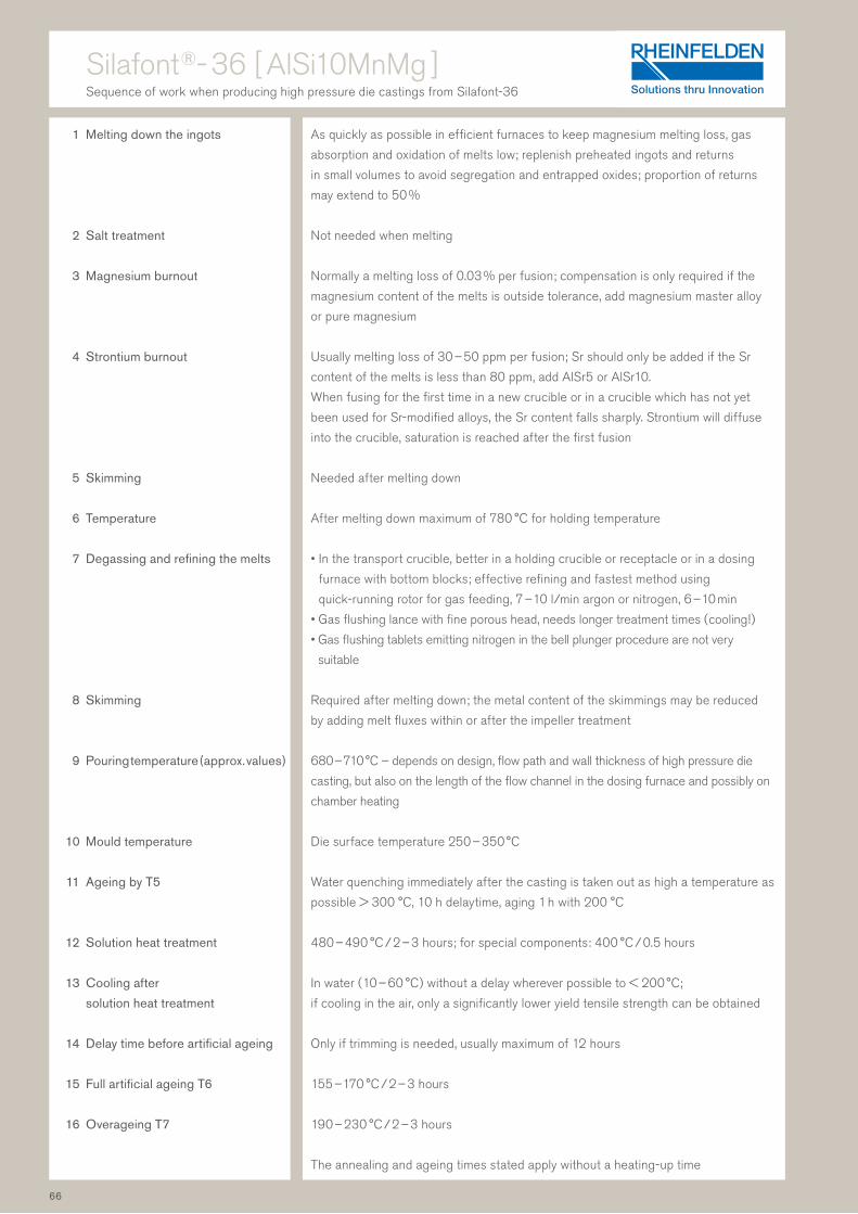
1 Melting down the ingots
2 Salt treatment
3 Magnesium burnout
4 Strontium burnout
5 Skimming
6 Temperature
7 Degassing and refining the melts
8 Skimming
9 Pouring temperature (approx. values )
10 Mould temperature
11 Ageing by T5
12 Solution heat treatment
13 Cooling after
solution heat treatment
14 Delay time before artificial ageing
15 Full artificial ageing T6
16 Overageing T7
Silafont ®- 36 [ AlSi10MnMg ]Sequence of work when producing high pressure die castings from Silafont-36
As quickly as possible in efficient furnaces to keep magnesium melting loss, gas
absorption and oxidation of melts low; replenish preheated ingots and returns
in small volumes to avoid segregation and entrapped oxides; proportion of returns
may extend to 50 %
Not needed when melting
Normally a melting loss of 0.03 % per fusion; compensation is only required if the
magnesium content of the melts is outside tolerance, add magnesium master alloy
or pure magnesium
Usually melting loss of 30 – 50 ppm per fusion; Sr should only be added if the Sr
content of the melts is less than 80 ppm, add AlSr5 or AlSr10.
When fusing for the first time in a new crucible or in a crucible which has not yet
been used for Sr- modified alloys, the Sr content falls sharply. Strontium will diffuse
into the crucible, saturation is reached after the first fusion
Needed after melting down
After melting down maximum of 780 °C for holding temperature
• In the transport crucible, better in a holding crucible or receptacle or in a dosing
furnace with bottom blocks; effective refining and fastest method using
quick- running rotor for gas feeding, 7 – 10 l/min argon or nitrogen, 6 – 10 min
• Gas flushing lance with fine porous head, needs longer treatment times ( cooling ! )
• Gas flushing tablets emitting nitrogen in the bell plunger procedure are not very
suitable
Required after melting down; the metal content of the skimmings may be reduced
by adding melt fluxes within or after the impeller treatment
680 – 710 °C – depends on design, flow path and wall thickness of high pressure die
casting, but also on the length of the flow channel in the dosing furnace and possibly on
chamber heating
Die surface temperature 250 – 350 °C
Water quenching immediately after the casting is taken out as high a temperature as
possible > 300 °C, 10 h delaytime, aging 1 h with 200 °C
480 – 490 °C / 2 – 3 hours; for special components: 400 °C / 0.5 hours
In water ( 10 – 60 °C ) without a delay wherever possible to < 200 °C;
if cooling in the air, only a significantly lower yield tensile strength can be obtained
Only if trimming is needed, usually maximum of 12 hours
155 – 170 °C / 2 – 3 hours
190 – 230 °C / 2 – 3 hours
The annealing and ageing times stated apply without a heating-up time
66

Castasil ®- 37 [ AlSi9MnMoZr ]Sequence of work when producing high pressure die castings from Castasil-37
1 Refining
2 Melting down the ingots
3 Salt treatment
4 Strontium burnout
5 Skimming
6 Temperature after melting down
and in the dosing furnace
7 Degassing and refining the melts
8 Skimming
9 Pouring temperature ( approx. values )
10 Mould temperature
11 Die chamber temperature
Clean furnace, crucible, treatment and casting tools to avoid impurities from
unwanted elements such as Cu, Zn and especially Mg !
The melt should be quickly heated to above 670 °C to avoid segregations, e. g. of the
solid solution containing Mn in the melt. The temperature of melt should not exceed
780 °C. An Sr melting loss should be expected when melting and keeping warm –
the higher the temperature, the greater the loss. Sr melting loss should be expected
in particular when melting down returns and degassing treatment is recommended to
remove the H2 and oxides. As the Sr content increases, so does the tendency for the
melt to absorb hydrogen; this should not therefore exceed 350 ppm.
Not needed when melting
Usually melting loss of 30 – 50 ppm per fusion; Sr should only be added if the Sr
content of the melts is less than 60 ppm, add AlSr5 or AlSr10.
When fusing for the first time in a new crucible or in a crucible which has not yet
been used for Sr-modified alloys, the Sr content falls sharply. Strontium will diffuse
into the crucible; saturation is reached after the first fusion
Needed after melting down; as well as their potential for danger, cold tools may
result in molybdenum segregation
After melting down maximum of 780 °C for holding temperature. Don’t keep the melt
at temperature below 680 °C and steer melt if possible.
Recomended temperature in the dosing furnace: 710 – 720 °C
• In the transport crucible, better in casting or dosing furnace; effective refining and
fastest method using quick-running rotor for gas feeding, 7 – 10 l/min argon or ni-
trogen, 6 – 10 min; during degassing in the transport crucible, cooling of 30 – 50 °C
should be expected
• Gas flushing lance with fine porous head, needs longer treatment times ( cooling ! )
• Tablets for melt cleaning are inefficient
Required after degassing; the metal content of the skimmings may be reduced by
adding melt fluxes during or after impeller treatment
680 – 720 °C depends on design, flow path and wall thickness of high pressure
die casting, but also on the length and insulation of the flow channel from the dosing
furnace and on use of shot sleeve heating.
Temperature losses may cause initial solidification and should therefore be avoided
250 – 350 °C, depending on cast and requirements of mechanical properties
As a rule: the warmer the mould, the higher the elongation and the lower the
strength.
Preheat the chamber electrical or with oil > 200 °C
67

1 Melting down the ingots
2 Magnesium burnout
3 Skimming
4 Temperature after melting down
5 Degassing and refining the melts
6 Skimming and grain refining
7 Modification
8 Pouring temperature ( approx. values )
Sand casting
Gravity die casting
9 Model design
10 Gravity die temperature
11 Removal of casting
Castadur ®- 30 [ AlZn3Mg3Cr ]Sequence of work when producing castings from Castadur-30
The crucibles used must not release any silicon to the alloy ( maximum silicon content
0.14 % ). Hot cracking sensitivity increases at higher silicon contents. The crucible
usually has to be rinsed with Al99.5 or AlMg alloy for this purpose. Melting down
should take place as quickly as possible in an efficient furnace so that zinc and
magnesium melting loss, gas absorption and oxidation of melts remain low. Pre-
heated ingots and returns should be replenished in small quantities. The high chrome
content may result in segregation at low holding temperatures below 670 °C
combined with long standing times. Salt treatment is not needed when melting
Melting loss of 0.1 % per fusion usually occurs and can be ignored
Needed after melting down
Maximum of 820 °C ( check temperature ! )
When using an impeller or gas flushing lance, the high temperature loss during treat-
ment should be taken into account. Recommended starting temperature: > 780 °C
• Effective refining and fastest method using quick-running gas rotor, 7 – 10 l/min
argon or nitrogen, 3 – 6 min
• Gas flushing lance with fine porous head, needs longer treatment times
A Quality of DI <1 can be easily achieved and maintained with effective refining
Is not needed with Castadur-30 after melting down ingot material
After a longer holding phase and with a high use of returns, a small
addition of grain refiners is recommended, e. g. grain refiner
tablets or AlTi5B1 wire ( 0.5 kg/t ) can be added just before pouring
Not needed as contains no silicon
Varies depending on casting method, design, size and wall thickness of castings:
720 – 760 °C ( recommendation 730 °C )
730 – 760 °C ( recommendation 750 °C )
Shrinkage of 1.0 – 1.3 %
The high centre line formation of blowholes must be remedied by specific
solidification. The ingate and feeder head design should be selected accordingly
250 – 400 °C depending on casting; at high gravity die temperatures,
fewer cracks form; we therefore recommend: 350 °C
When removed from the moulding box or gravity die, castings are still very soft.
Castings with dimensional accuracy measurements must be removed with care
68

1 Melting down the ingots
2 Salt treatment
3 Magnesium burnout
4 Skimming
5 Temperature after melting down
6 Degassing and refining the melts
7 Skimming and grain refining
8 Modification with Sr
Sand casting with Na
Gravity die casting with Na
9 Refining and skimming
10 Pouring temperature ( approx. values )
Sand casting
Gravity die casting
11 Gravity die temperature
12 Heat treatment
Unifont ®- 90 [ AlZn10Si8Mg ]Sequence of work when producing castings from Unifont-90
As quickly as possible in efficient furnaces to keep Mg melting loss, gas absorption
and oxidation of melts low; replenish preheated ingots and returns in small volumes;
even a low level of Cu impurity of 0,05 % in the melt composition should also be
avoided!
Not needed when melting
Normally melting loss of 0.05 % per fusion; compensation is needed if the total
magnesium content falls below 0.25 % and is achieved by adding Mg master alloy
or pure magnesium
Needed after melting down
Maximum of 780 °C ( check temperature ! )
• Effective refining and fastest method using quick-running rotor for gas feeding,
7 – 10 l/min argon or nitrogen, 6 – 10 min
• Gas flushing lance with fine porous head, needs longer treatment times ( cooling ! )
• Gas flushing tablet emitting nitrogen at a rate of 150 – 350 l nitrogen/kg ( bell
plunger procedure )
Best for Unifont-90 with granular microstructure, with a high proportion of returns:
after skimming, grain refining with TiB master alloy or tabletted fluxes on nucleation
states in excess of = 9, i. e. grain size of less than 2.5 mm2
When using permanently modified ingots only if the strontium content has fallen
below 0.015 %; modify with AlSr master alloy, preferably one containing only 5 %
strontium
• With 0.03 – 0.04 vacuum-packed sodium or 0.2 – 0.3 exothermic modification
tablets or 0.05 – 0.2 salt granulate ( details provided as % of charge weight )
• Thick-walled gravity die casting and gravity die casting with sand cores: with
0.015 – 0.025 vacuum-packed sodium or 0.1 – 0.2 exothermic modification tablets
or 0.05 – 0.2 salt granulate ( details provided as % of charge weight )
Thin-walled gravity die casting is only modified with sodium in rare cases
Gas treatment with rotor is the preferred option, e. g. using integrated melt
processing while adding sodium-salt granulate and gas refining at the same time
Varies depending on casting method, design, size and wall thickness of castings:
710 – 740 °C
720 – 750 °C
300 – 400 °C depending on casting
Only if the cast is being used straight away: age at 100 – 120 °C / 10 – 16 hours
69

1 Melting down the ingots
2 Salt treatment when melting down
3 Magnesium burnout
4 Skimming
5 Temperature after melting down
6 Degassing and refining the melts
7 Skimming after refining treatment
8 Grain refinement
9 Standing and skimming
10 Pouring temperature ( approx. values )
Sand casting
Gravity die casting
11 Gravity die temperature
12 Solution heat treatment
13 Cooling solution heat treatment
temperature
14 Delay time before artificial ageing
15 Artificial ageing for artificial
hardening
Peraluman ®- 56 [ AlMg5Si ]Sequence of work when producing castings from Peraluman-56
As quickly as possible in efficient furnaces to keep Mg melting loss, oxidation and
gas absorption of melts low; even a low level of Cu impurity in the melt composition
should also be avoided
Not needed when melting ingots; useful for avoiding oxidation when using small
returns
Not important
Needed after melting down !
Normally maximum of 780 °C ( check temperature ! )
Needed !
• Effective refining and fastest method using quick-running rotor for gas feeding,
7 – 10 l/min argon or nitrogen, 6 – 10 min
• Gas flushing lance with fine porous head, needs longer treatment times ( cooling ! )
• Gas flushing tablets do not achieve the necessary effect !
Also vacuum treatment with nitrogen recirculation is possible
Careful skimming absolutely essential, if using salt, ensure a Na-free salt mixture
Needed with grain refiner based on TiB2: 0.15 – 0.30 % tabletted fluxes,
0.1 – 0.2 % master alloy wire ( volume in relation to weight of melt )
Leave to stand for several minutes, then carefully skim
700 – 740 °C
710 – 770 °C
350 – 420 °C, depending on casting
Slowly heat up to 540 – 550 °C, annealing time of 4 – 8 hours
The annealing times stated apply without a heating-up time
In water of around 20 °C to 60 °C without a delay wherever possible
Maximum of 24 hours
160 – 170 °C / 8 – 10 hours
70

1 Melting down the ingots
2 Salt treatment
3 Magnesium burnout
4 Skimming
5 Temperature after melting down
6 Temperature in holding furnace
7 Degassing and refining the melts
8 Skimming
9 Grain refining
10 Modification
11 Pouring temperature ( approx. values )
12 Die temperature
13 Quenching castings after removal
from mould
14 Heat treatment
15 stress-relief annealing
Magsimal ®- 59 [ AlMg5Si2Mn ]Sequence of work when producing high pressure die castings from Magsimal-59
As quickly as possible in efficient furnaces to keep Mg melting loss, gas absorption
and oxidation of melts low; replenish preheated ingots and returns in small volumes to
avoid segregation; use refractory materials with a high clay content; avoid phospho-
rous and sodium absorption
Prohibited ! There is a risk of Na pick up
Normally melting loss of 0.1 % per fusion, correction not normally needed; if the Mg
content is significantly below 5.0 %, add pure magnesium of maximum 0.5 %
Needed after melting down
Maximum of 780 °C ( check temperature ! )
Do not allow to fall below 650 °C and keep melt moving by means of:
• convection
• rotor ( impeller )
Do not use deep furnace with cover heating if melt is inactive !
Use refractory materials with a high clay content!
• Effective refining and fastest method using quick-running rotor for gas feeding,
7 – 10 l/min argon or nitrogen, 6 – 10 min
• Gas flushing lance with fine porous head, needs longer treatment times ( cooling ! )
• Gas flushing tablets do not achieve the necessary effect !
Careful skimming needed
Only totally Na-free salts may be used to reduce the metal content of skimmings!
Prohibited !
Prohibited ! The elongation achievable would be reduced considerably
690 – 730 °C, varies depending on design, size and wall thickness of high pressure
die castings
200 – 300 °C, depending on casting and requirements of mechanical properties
As a rule: the warmer the mould, the higher the elongation and the lower the
strength.
Immediate quenching in water reduces the yield tensile strength and
increases elongation
Normally none
Only in special cases for T5 and O; if necessary, age T5 at up to 250 °C and
for up to 90 min, the yield tensile strength will increase and elongation decrease;
if necessary, age O at between 320 °C and 380 °C and for up to 90 min,
the yield tensile strength will decrease and elongation increase
71
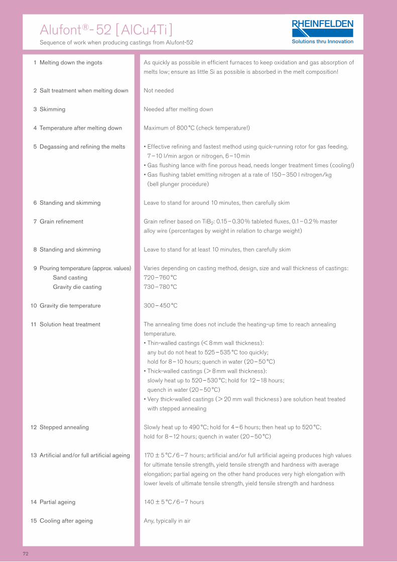
1 Melting down the ingots
2 Salt treatment when melting down
3 Skimming
4 Temperature after melting down
5 Degassing and refining the melts
6 Standing and skimming
7 Grain refinement
8 Standing and skimming
9 Pouring temperature ( approx. values )
Sand casting
Gravity die casting
10 Gravity die temperature
11 Solution heat treatment
12 Stepped annealing
13 Artificial and/or full artificial ageing
14 Partial ageing
15 Cooling after ageing
Alufont ®- 52 [ AlCu4Ti ]Sequence of work when producing castings from Alufont-52
As quickly as possible in efficient furnaces to keep oxidation and gas absorption of
melts low; ensure as little Si as possible is absorbed in the melt composition!
Not needed
Needed after melting down
Maximum of 800 °C ( check temperature ! )
• Effective refining and fastest method using quick-running rotor for gas feeding,
7 – 10 l/min argon or nitrogen, 6 – 10 min
• Gas flushing lance with fine porous head, needs longer treatment times ( cooling ! )
• Gas flushing tablet emitting nitrogen at a rate of 150 – 350 l nitrogen/kg
( bell plunger procedure )
Leave to stand for around 10 minutes, then carefully skim
Grain refiner based on TiB2: 0.15 – 0.30 % tableted fluxes, 0.1 – 0.2 % master
alloy wire ( percentages by weight in relation to charge weight )
Leave to stand for at least 10 minutes, then carefully skim
Varies depending on casting method, design, size and wall thickness of castings:
720 – 760 °C
730 – 780 °C
300 – 450 °C
The annealing time does not include the heating-up time to reach annealing
temperature.
• Thin-walled castings ( < 8 mm wall thickness ):
any but do not heat to 525 – 535 °C too quickly;
hold for 8 – 10 hours; quench in water ( 20 – 50 °C )
• Thick-walled castings ( > 8 mm wall thickness ):
slowly heat up to 520 – 530 °C; hold for 12 – 18 hours;
quench in water ( 20 – 50 °C )
• Very thick-walled castings ( > 20 mm wall thickness ) are solution heat treated
with stepped annealing
Slowly heat up to 490 °C; hold for 4 – 6 hours; then heat up to 520 °C;
hold for 8 – 12 hours; quench in water ( 20 – 50 °C )
170 ± 5 °C / 6 – 7 hours; artificial and/or full artificial ageing produces high values
for ultimate tensile strength, yield tensile strength and hardness with average
elongation; partial ageing on the other hand produces very high elongation with
lower levels of ultimate tensile strength, yield tensile strength and hardness
140 ± 5 °C / 6 – 7 hours
Any, typically in air
72

Technical information
This chapter details the chemical, mechanical and physical properties of the aluminium casting alloys
from RHEINFELDEN ALLOYS. They can be compared using tables.
Advice is also provided on how to work with our casting alloys in the melt process and how to gain
optimum pouring results.
Various stages of processing are given in detail:
• Grain refinement
• Modification
• Quality of melt
• Refining the melts
• Melt testing
• Artificial ageing, heat treatment and self-ageing
• Heat treatment for high pressure die castings
• Fatigue strength
• Corrosion and corrosion protection
• Producing welded designs
• Joining techniques for high pressure die castings
• Machining
This part of the manual has been updated by our customer support staff.
We consider this a very important part of the manual as it isn’t just the quality of casting alloy used
which is key to successful applications, the right way of working before, during and after pouring is also
of great importance. More questions will certainly arise during your work and as new developments
enter the market. The RHEINFELDEN ALLOYS foundry specialists will happily answer these.
The mechanical properties are based on in-house measurements of our alloys and most exceed the
values stipulated in the EN 1706 European standard.
The mechanical values were measured for sand and gravity die castings on separately cast test pieces
and on test pieces taken from the castings; for high pressure die casting, values were only measured
on test pieces. The ranges of mechanical properties stated indicate the performance of the alloys and
the amount of scatter depending on material and pouring. The respective maximum value is for the
designer’s information. These values can also be reached in the casting or sub-areas with favourable
casting conditions and corresponding casting technology work. The figures provided in brackets are
minimum values in the casting with wall thicknesses of up to 20 mm. The properties of the aluminium
casting alloys are affected by metal impurity, especially by increased levels of iron.
The primary aluminium casting alloys supplied by RHEINFELDEN ALLOYS have an iron content of
less than 0.15 % unless higher Fe contents are needed. The analysis limits in the alloys we supply are
precisely defined in order to ensure good uniformity in the casting process and other properties.
73

Chemical compositions
Alloys of a consistently high purity are key to producing
high-quality castings. The RHEINFELDEN ALLOYS quality
system allows this level of purity to be met.
The main alloy components are printed in bold. Individual values
in the table are the maximum contents of alloy and accompany-
ing elements. The alloys which RHEINFELDEN ALLOYS supplies
sometimes have narrower alloy component ranges and a lower
content of impurity than stipulated in the standard. This ensures
good uniformity in the casting process and other properties.
European standard EN 1676 for alloyed aluminium in ingots
applies.
The numerical alloy denomination is based on the European
standard ( EN ). Alloys without these denominations are not in-
cluded in the EN or have wider limits in composition.
Alloys with special compositions can be produced by agreement.
In the case of aluminium-silicon alloys, on request a modified
microstructure with sodium ( modified subsequently or in
advance ) or strontium ( permanently modified ) can be set rather
than the granular microstructure. This choice is indicated by
the denomination ( Na/Sr ) in the last column.
Brand name Chemical Numerical denomination denomination
Anticorodal-04 AlSi0.5Mg
Anticorodal-50 AlSi5Mg
Anticorodal-70 AlSi7Mg0.3 42 100
Anticorodal-78dv AlSi7Mg0.3 42 100
Anticorodal-71 AlSi7Mg0.3 - E
Anticorodal-72 AlSi7Mg0.6 42 200
Silafont-30 AlSi9Mg 43 300
Silafont-36 AlSi10MnMg 43 500
Silafont-38 AlSi9MnMgZn
Silafont-09 AlSi9 44 400
Silafont-13 AlSi11
Silafont-20 AlSi11Mg 44 000
Silafont-70 AlSi12CuNiMg 48 000
Silafont-90 AlSi17Cu4Mg
Castaman-35 AlSi10MnMg
Castasil-37 AlSi9MnMoZr
Castasil-21 AlSi9Sr
Unifont-90 AlZn10Si8Mg 71 100
Unifont-94 AlZn10Si8Mg
Castadur-30 AlZn3Mg3Cr
Castadur-50 AlZn5Mg
Peraluman-30 AlMg3 51 100
Peraluman-36 AlMg3Si
Peraluman-50 AlMg5 51 300
Peraluman-56 AlMg5Si 51 400
Magsimal-59 AlMg5Si2Mn 51 500
Alufont-47 AlCu4TiMg 21 000
Alufont-48 AlCu4TiMgAg
Alufont-52 AlCu4Ti 21 100
Alufont-60 AlCu5NiCoSbZr
Thermodur-72 AlMg7Si3Mn
Thermodur-73 AlSi11Cu2Ni2Mg2Mn
Rotoren-Al 99.7 Al99.7 - E
Aluman-16 AlMn1.6
74
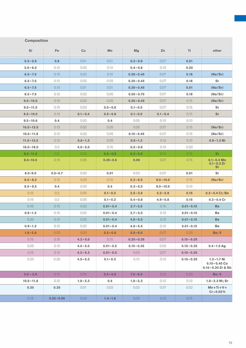
Composition
Si Fe Cu Mn Mg Zn Ti other
Anticorodal-04 AlSi0.5Mg
Anticorodal-50 AlSi5Mg
Anticorodal-70 AlSi7Mg0.3 42 100
Anticorodal-78dv AlSi7Mg0.3 42 100
Anticorodal-71 AlSi7Mg0.3 - E
Anticorodal-72 AlSi7Mg0.6 42 200
Silafont-30 AlSi9Mg 43 300
Silafont-36 AlSi10MnMg 43 500
Silafont-38 AlSi9MnMgZn
Silafont-09 AlSi9 44 400
Silafont-13 AlSi11
Silafont-20 AlSi11Mg 44 000
Silafont-70 AlSi12CuNiMg 48 000
Silafont-90 AlSi17Cu4Mg
Castaman-35 AlSi10MnMg
Castasil-37 AlSi9MnMoZr
Castasil-21 AlSi9Sr
Unifont-90 AlZn10Si8Mg 71 100
Unifont-94 AlZn10Si8Mg
Castadur-30 AlZn3Mg3Cr
Castadur-50 AlZn5Mg
Peraluman-30 AlMg3 51 100
Peraluman-36 AlMg3Si
Peraluman-50 AlMg5 51 300
Peraluman-56 AlMg5Si 51 400
Magsimal-59 AlMg5Si2Mn 51 500
Alufont-47 AlCu4TiMg 21 000
Alufont-48 AlCu4TiMgAg
Alufont-52 AlCu4Ti 21 100
Alufont-60 AlCu5NiCoSbZr
Thermodur-72 AlMg7Si3Mn
Thermodur-73 AlSi11Cu2Ni2Mg2Mn
Rotoren-Al 99.7 Al99.7 - E
Aluman-16 AlMn1.6
0.3 – 0.6 0.8 0.01 0.01 0.3 – 0.6 0.07 0.01
5.0 – 6.0 0.15 0.02 0.10 0.4 – 0.8 0.10 0.20
6.5 – 7.5 0.15 0.02 0.10 0.30 – 0.45 0.07 0.18 ( Na/Sr )
6.5 – 7.5 0.12 0.02 0.05 0.30 – 0.45 0.07 0.18 Sr
6.5 – 7.5 0.15 0.01 0.01 0.30 – 0.45 0.07 0.01 ( Na/Sr )
6.5 – 7.5 0.15 0.02 0.05 0.50 – 0.70 0.07 0.18 ( Na/Sr )
9.0 – 10.0 0.15 0.02 0.05 0.30 – 0.45 0.07 0.15 ( Na/Sr )
9.5 – 11.5 0.15 0.03 0.5 – 0.8 0.1 – 0.5 0.07 0.15 Sr
8.5 – 10.0 0.15 0.1 – 0.4 0.5 – 0.8 0.1 – 0.5 0.1 – 0.4 0.15 Sr
9.5 – 10.6 0.4 0.02 0.4 0.05 0.10 0.10
10.0 – 13.5 0.15 0.02 0.05 0.05 0.07 0.15 ( Na/Sr )
10.0 – 11.8 0.15 0.02 0.05 0.10 – 0.45 0.07 0.15 ( Na/Sr )
11.0 – 13.5 0.15 0.8 – 1.3 0.05 0.9 – 1.3 0.10 0.10 0.8 – 1.3 Ni
16.0 – 18.0 0.3 4.0 – 5.0 0.15 0.5 – 0.6 0.10 0.20
9.5 – 11.0 0.2 0.03 0.5 – 0.8 0.2 – 0.5 0.10 0.15 Sr
8.5–10.5 0.15 0.05 0.35–0.6 0.06 0.07 0.15 0.1 – 0.3 Mo 0.1 – 0.3 Zr Sr
8.0–9.0 0.5–0.7 0.02 0.01 0.03 0.07 0.01 Sr
8.5 – 9.3 0.15 0.03 0.10 0.3 – 0.5 9.0 – 10.0 0.15 ( Na/Sr )
8.5 – 9.5 0.4 0.03 0.4 0.3 – 0.5 9.0 – 10.0 0.10
0.15 0.2 0.05 0.1 – 0.2 2.5 – 3.0 2.2 – 2.8 0.15 0.2 – 0.4 Cr; Be
0.15 0.2 0.05 0.1 – 0.2 0.4 – 0.8 4.9 – 5.8 0.15 0.2 – 0.4 Cr
0.45 0.15 0.02 0.01 – 0.4 2.7 – 3.5 0.10 0.01 – 0.15 Be
0.9 – 1.3 0.15 0.02 0.01 – 0.4 2.7 – 3.5 0.10 0.01 – 0.15 Be
0.30 0.15 0.02 0.01 – 0.4 4.8 – 5.5 0.10 0.01 – 0.15 Be
0.9 – 1.3 0.15 0.02 0.01 – 0.4 4.8 – 5.5 0.10 0.01 – 0.15 Be
1.8 – 2.6 0.20 0.03 0.5 – 0.8 5.0 – 6.0 0.07 0.20 Be; V
0.15 0.15 4.2 – 5.0 0.10 0.20 – 0.35 0.07 0.15 – 0.25
0.05 0.10 4.0 – 5.0 0.01 – 0.5 0.15 – 0.35 0.05 0.15 – 0.35 0.4 – 1.0 Ag
0.15 0.15 4.2 – 5.2 0.01 – 0.5 0.03 0.07 0.15 – 0.25
0.20 0.30 4.5 – 5.2 0.1 – 0.3 0.10 0.10 0.15 – 0.30 1.3 – 1.7 Ni 0.10 – 0.40 Co 0.10 – 0.30 Zr & Sb
3.0 – 3.8 0.15 0.05 0.5 – 0.8 7.0 – 8.0 0.10 0.20 Be; V
10.0 – 11.8 0.15 1.8 – 2.3 0.4 1.8 – 2.3 0.10 0.10 1.8 – 2.3 Ni; Sr
0.20 0.25 0.01 0.02 0.02 0.07 0.02 Mn + Ti + V + Cr ≤ 0.02 %
0.15 0.20 – 0.90 0.03 1.4 – 1.6 0.05 0.10 0.15
75

Mechanical properties
Anticorodal-04 AlSi0.5Mg S F 60 – 100 (50) 90 – 130 (80) 15 – 20 (10) 35 – 40 (35)
S T7 160 – 180 (150) 190 – 210 (180) 3 – 5 (3) 70 – 75 (70)
K F 80 – 120 (70) 100 – 140 (90) 18 – 22 (12) 40 – 45 (40)
K T7 170 – 190 (150) 200 – 220 (190) 3 – 6 (3) 70 – 80 (70)
D F 80 – 120 100 – 140 7 – 12 40 – 45
Anticorodal-50 AlSi5Mg S F 100 – 130 (90) 140 – 180 (130) 2 – 4 (1) 60 – 70 (55) 60 – 65
S T4 150 – 180 (120) 200 – 270 (150) 4 – 10 (2) 75 – 90 (70) 70 – 75
S T6 220 – 290 (160) 260 – 320 (180) 2 – 4 (1) 95 – 115 (85) 70 – 75
K F 120 – 160 (100) 160 – 200 (140) 2 – 5 (1) 60 – 75 (60) 70 – 75
K T4 160 – 190 (130) 210 – 270 (170) 5 – 10 (3) 75 – 90 (70) 80 – 85
K T6 240 – 290 (180) 260 – 320 (190) 2 – 7 (1) 100 – 115 (90) 80 – 85
Anticorodal-70 42 100 AlSi7Mg0.3 S F 80 – 140 (80) 140 – 220 (140) 2 – 6 (2) 45 – 60 (45)
S T64 120 – 170 (120) 200 – 270 (200) 4 – 10 (4) 60 – 80 (55)
S T6 220 – 280 (200) 240 – 320 (240) 3 – 6 (2.5) 80 – 110 (80) 90 – 100
K F 90 – 150 (90) 180 – 240 (180) 4 – 9 (2) 55 – 70 (50)
K T64 180 – 200 (140) 250 – 270 (220) 8 – 12 (5) 80 – 95 (80)
K T6 220 – 280 (200) 290 – 340 (250) 5 – 9 (3.5) 90 – 125 (90)
Anticorodal-71 AlSi7Mg0.3 - E S T7 160 – 200 (150) 220 – 250 (210) 2 – 4 (2) 70 – 80 (70)
K T7 160 – 200 (150) 220 – 250 (210) 4 – 6 (3) 70 – 80 (70)
Anticorodal-72 42 200 AlSi7Mg0.6 S T6 220 – 280 (220) 250 – 320 (250) 1 – 2 (1) 90 – 110 (90) 90 – 110
K T64 210 – 240 (150) 290 – 320 (230) 6 – 8 (3) 90 – 100 (90)
K T6 240 – 280 (220) 320 – 350 (270) 4 – 6 (2.5) 100 – 115 (100) 110 – 115
Silafont-30 43 300 AlSi9Mg S F 80 – 140 (80) 160 – 220 (150) 2 – 6 (2) 50 – 70 (50) 65 – 75
S T6 200 – 310 (180) 250 – 330 (220) 2 – 5 (2) 80 – 115 (75) 80 – 100
K F 90 – 150 (90) 180 – 240 (180) 2 – 9 (2) 60 – 80 (60) 80 – 100
K T64 180 – 210 (140) 250 – 290 (220) 6 – 10 (3) 80 – 90 (80)
K T6 210 – 310 (190) 290 – 360 (240) 4 – 7 (2) 90 – 120 (90) 90 – 110
Silafont-36 43 500 AlSi10MnMg D F 120 – 150 250 – 290 5 – 11 75 – 95 80 – 90
D T5 155 – 245 275 – 340 4 – 9 80 – 110
D T4 95 – 140 210 – 260 15 – 22 60 – 75
D T6 210 – 280 290 – 340 7 – 12 90 – 110
D T7 120 – 170 200 – 240 15 – 20 60 – 75
Silafont-38 AlSi9MnMgZn D F 140 – 160 270 – 300 3 – 7 80 – 105
D Water -T6 230 – 260 300 – 345 6 – 9 90 – 115
D Air -T6 180 – 200 250 – 275 8 –10 80 –110
Silafont-09 44 400 AlSi9 D F 120 – 180 220 – 280 4 – 8 55 – 80 60 – 70
Silafont-13 AlSi11 S F 70 – 120 (70) 150 – 210 (150) 7 – 13 (6) 45 – 60 (45) 55 – 70
S O 60 – 120 (60) 150 – 210 (150) 9 – 15 (8) 45 – 60 (45) 85 – 100
K F 80 – 150 (80) 170 – 240 (160) 7 – 16 (6) 45 – 60 (45) 70 – 90
K O 60 – 120 (60) 180 – 240 (160) 10 – 18 (10) 45 – 65 (45) 90 – 110
Silafont-20 44 000 AlSi11Mg S F 80 – 140 (70) 170 – 220 (170) 2 – 4 (1.5) 50 – 60 (50) 65 – 75
S T6 120 – 300 (110) 200 – 320 (200) 1 – 3 (0.5) 65 – 120 (55) 90 – 120
K F 80 – 130 (80) 180 – 230 (180) 3 – 16 (3) 55 – 75 (55) 80 – 100
K T6 125 – 320 (120) 210 – 350 (210) 4 – 15 (3) 70 – 125 (70) 100 – 120
Silafont-70 48 000 AlSi12CuNiMg S F 120 – 170 (110) 130 – 180 (120) 0.5 – 1.5 (0.5) 80 – 90 (80) 75 – 85
K F 190 – 260 (180) 200 – 270 (190) 1.0 – 2.5 (0.5) 90 – 105 (90) 80 – 90
K T6 320 – 390 (280) 350 – 400 (300) 0.5 – 2.0 (0.5) 135 – 160 (130) 100 – 110
K T5 185 – 210 (150) 200 – 230 (180) 0.5 – 2.0 (0.5) 90 – 110 (90)
Silafont-90 AlSi17Cu4Mg K F 170 – 225 (160) 180 – 235 (170) 0.4 – 0.9 (0.3) 110 – 120 (110)
K T5 160 – 225 (160) 165 – 230 (165) 0.4 – 0.8 (0.3) 105 – 115 (110)
D T5 220 – 265 230 – 295 0.5 – 1.0 110 – 120
Castaman-35 AlSi10MnMg D T6 180 – 260 250 – 320 6 – 12 80 – 110
Alloy denomination
Numerical denomination
Chemical denominationg
Casting process
Treatment state
0.2 %-yield tensilestrength
Rp0.2
MPa
Ultimate tensile strength
Rm MPa
Elongation A %
Brinell hardness
HBW 5/250 – 30
Fatigue resistance
bw MPa
76

The details relating to the casting method use the following abbreviations: S Sand casting K Gravity die casting D High pressure die casting
1 ) Long-term aged; tested at temperature
Castasil-37 AlSi9MnMoZr D 2 – 3 mm F 120 – 150 260 – 300 10 – 14 60 – 75
D 3 – 5 mm F 100 – 130 230 – 280 10 – 14 60 – 75 80 – 95
D 5 – 7 mm F 80 – 110 200 – 250 10 – 14 60 – 75
Castasil-21 AlSi9Sr D F 90 – 100 200 – 230 6 – 9 60 – 70
D O 80 – 90 170 – 190 9 – 15 55 – 65
Unifont-90 71 100 AlZn10Si8Mg S T1 190 – 230 (170) 220 – 250 (180) 1 – 2 (1) 90 – 100 (90) 80 – 100
K T1 220 – 250 (220) 280 – 320 (230) 1 – 4 (1) 100 – 120 (95) 90 – 110
Unifont-94 AlZn10Si8Mg D T1 230 – 280 300 – 350 1 – 4 105 – 120 70 – 90
Castadur-30 AlZn3Mg3Cr K T1 140 – 160 260 – 290 10 – 20 75 – 85
Castadur-50 AlZn5Mg S T1 160 – 200 220 – 280 5 – 10 75 – 85
Peraluman-30 51 100 AIMg3 S F 70 – 100 (60) 170 – 190 (140) 4 – 8 (4) 50 – 60 (45) 70 – 80
S T6 140 – 160 (110) 200 – 240 (160) 6 – 8 (5) 65 – 75 (60) 75 – 85
K F 70 – 100 (70) 170 – 210 (150) 9 – 16 (6) 50 – 60 (50) 90 – 100
K T6 140 – 160 (110) 240 – 260 (180) 15 – 20 (12) 70 – 80 (70) 100 – 110
Peraluman-36 AIMg3Si S F 80 – 100 (70) 140 – 190 (130) 3 – 8 (3) 50 – 60 (45) 60 – 65
S T6 160 – 220 (140) 220 – 280 (180) 2 – 8 (2) 70 – 90 (65) 75 – 80
K F 70 – 100 (70) 160 – 210 (160) 6 – 14 (5) 50 – 65 (50) 70 – 80
K T6 160 – 220 (150) 250 – 300 (220) 5 – 15 (5) 75 – 90 (75) 80 – 90
Peraluman-50 51 300 AIMg5 S F 100 – 120 (90) 190 – 250 (170) 10 – 15 (8) 55 – 70 (50) 60 – 80
K F 100 – 140 (100) 200 – 260 (180) 10 – 25 (8) 60 – 75 (55) 70 – 80
Peraluman-56 51 400 AlMg5Si S F 110 – 130 (100) 160 – 200 (140) 3 – 4 (2) 60 – 80 (55) 60 – 80
S T6 110 – 160 (110) 180 – 220 (160) 3 – 4 (2) 70 – 80 (65) 70 – 90
K F 110 – 150 (100) 180 – 240 (150) 3 – 5 (3) 65 – 85 (60) 70 – 80
K T6 110 – 160 (110) 210 – 260 (200) 3 – 18 (5) 75 – 85 (70) 70 – 90
Magsimal-59 51 500 AlMg5Si2Mn D 2 – 4 mm F 160 – 220 310 – 340 12 – 18 85 – 105 90 – 100
D 4 – 6 mm F 140 – 170 250 – 320 9 – 14 80 – 90
D 6 – 12 mm F 120 – 145 220 – 260 8 – 12 75 – 85
Alufont-47 21 000 AlCu4MgTi S T4 220 – 280 (180) 300 – 400 (240) 5 – 15 (3) 90 – 115 (85) 80 – 100
S T6 240 – 350 (220) 350 – 420 (280) 3 – 10 (1) 95 – 125 (90) 80 – 100
K T4 220 – 300 (200) 320 – 420 (280) 8 – 18 (5) 95 – 115 (90) 100 – 110
Alufont-48 AICu4MgAgTi S T64 200 – 270 (180) 370 – 430 (320) 14 – 18 (7) 105 – 120 (100)
S T6 410 – 450 (320) 460 – 510 (380) 3 – 7 (2) 130 – 150 (125) 80 – 100
K T6 410 – 460 (340) 460 – 510 (440) 5 – 8 (3) 130 – 150 (130) 100 – 110
Alufont-52 21 100 AlCu4Ti S T64 210 – 240 (180) 300 – 360 (260) 8 – 15 (4) 90 – 100 (90) 80 – 100
S T6 300 – 420 (280) 400 – 475 (350) 3 – 4 (2) 125 – 145 (120) 80 – 100
K T64 210 – 250 (190) 360 – 400 (300) 12 – 20 (10) 90 – 120 (90) 100 – 110
K T6 310 – 400 (300) 420 – 475 (400) 7 – 16 (4) 130 – 145 (130) 100 – 110
Alufont-60 AlCu5NiCoSbZr S T7 145 – 165 (140) 180 – 220 (180) 1 – 1.5 (1) 85 – 95 (85) 90 – 100
S O 160 – 180 (160) 180 – 200 (180) 1 – 1.5 (1) 80 – 90 (80) 90 – 100
Thermodur-72 AlMg7Si3Mn D 20 °C 190 – 220 350 – 380 7 – 10 80 – 100
D 150 °C /500 h 1) 220 – 245 260 – 290 < 15
D 225 °C / 500 h 1) 150 – 175 180 – 205 < 20
Thermodur-73 AlSi11Mg2Cu2Ni2 D 20 °C 270 – 300 300 – 320 < 1 130 – 150
D 150 °C / 500 h 1) 280 – 310 330 – 355 < 1
D 225 °C / 500 h 1) 130 – 155 250 – 280 1 – 2
Rotoren-Al 99.7 Al99.7 - E D F 20 – 40 80 – 120 10 – 25 15 – 25
Aluman-16 AlMn1.6 D F 90 – 120 160 – 180 8 – 15 40 – 60
S F 80 – 100 130 – 160 4 – 8 40 – 50
Alloy denomination
Numerical denomination
Chemical denominationg
Casting process
Treatment state
0.2 %-yield tensilestrength
Rp0.2
MPa
Ultimate tensile strength
Rm MPa
Elongation A %
Brinell hardness
HBW 5/250 – 30
Fatigueresistance
bw MPa
77

Physical properties
The details of physical properties relate to heat-treatable alloys in a heat-treated state. They are heavily
influenced by fluctuations in the alloy composition and the microstructure state. This explains why
some of the measurement ranges are so large. The details for the melt and solidification ranges take into
account the initial signs of partial melting resulting from segregation in the cast structure, which may
occur in particular when heating up quickly at far below the theoretical equilibrium temperature.
Anticorodal-04 AlSi0.5Mg 2.67 66 – 73 23 2.0
Anticorodal-50 AlSi5Mg 2.67 65 – 75 23 1.5
Anticorodal-70 AlSi7Mg0.3 2.66 69 – 75 22 1.6
Anticorodal-78dv AlSi7Mg0.3 2.66 69 – 75 22 1.6
Anticorodal-71 AlSi7Mg0.3 - E 2.66 69 – 75 22 1.8
Anticorodal-72 AlSi7Mg0.6 2.66 71 – 75 22 1.5
Silafont-30 AlSi9Mg 2.65 74 – 83 21 1.5
Silafont-36 AlSi10MnMg 2.64 74 – 83 21 1.5
Silafont-38 AlSi9MnMgZn 2.67 74 – 83 21 1.4
Silafont-09 AlSi9 2.65 62 – 78 21 1.4
Silafont-13 AlSi11 2.64 65 – 81 21 1.4
Silafont-20 AlSi11Mg 2.64 76 – 83 21 1.4
Silafont-70 AlSi12CuNiMg 2.68 77 – 83 21 1.2
Silafont-90 AlSi17Cu4Mg 2.73 77 – 83 18 1.1
Castaman-35 AlSi10MnMg 2.64 74 – 83 21 1.4
Castasil-37 AlSi9MnMoZr 2.69 68 – 75 21 1.3
Castasil-21 AlSi9Sr 2.65 62 – 78 21 1.7
Unifont-90 AlZn10Si8Mg 2.85 74 – 80 21 1.2
Unifont-94 AlZn10Si8Mg 2.85 74 – 80 21 1.2
Castadur-30 AlZn3Mg3Cr 2.74 70 – 72 24 1.2
Castadur-50 AlZn5Mg 2.78 71 – 74 24 1.3
Peraluman-30 AlMg3 2.66 63 – 73 24 1.3
Peraluman-36 AlMg3Si 2.66 66 – 74 24 1.2
Peraluman-50 AlMg5 2.63 63 – 73 24 1.2
Peraluman-56 AlMg5Si 2.63 68 – 75 24 1.1
Magsimal-59 AlMg5Si2Mn 2.63 70 – 80 24 1.1
Alufont-47 AlCu4TiMg 2.75 65 – 72 23 1.3
Alufont-48 AlCu4TiMgAg 2.79 65 – 72 23 1.3
Alufont-52 AlCu4Ti 2.75 65 – 73 23 1.3
Alufont-60 AlCu5NiCoSbZr 2.84 72 – 76 22.5 1.2
Thermodur-72 AlMg7Si3Mn 2.61 75 – 85
Thermodur-73 AlSi11Cu2Ni2Mg2Mn 2.74 85 – 90
Rotoren-Al 99.7 Al99.7 - E 2.67 65 – 70 24 2.3
Aluman-16 AlMn1.6 2.73 65 – 72 24 1.5
Brandname Chemical Density Young’s modulus Linear Thermal conductivity denomination ( approximate value ) thermal expansion 20 – 200 °C coeffizient 20 – 200 °C
kg/dm3 GPa
78

Anticorodal-04 AlSi0.5Mg 2.67 66 – 73 23 2.0
Anticorodal-50 AlSi5Mg 2.67 65 – 75 23 1.5
Anticorodal-70 AlSi7Mg0.3 2.66 69 – 75 22 1.6
Anticorodal-78dv AlSi7Mg0.3 2.66 69 – 75 22 1.6
Anticorodal-71 AlSi7Mg0.3 - E 2.66 69 – 75 22 1.8
Anticorodal-72 AlSi7Mg0.6 2.66 71 – 75 22 1.5
Silafont-30 AlSi9Mg 2.65 74 – 83 21 1.5
Silafont-36 AlSi10MnMg 2.64 74 – 83 21 1.5
Silafont-38 AlSi9MnMgZn 2.67 74 – 83 21 1.4
Silafont-09 AlSi9 2.65 62 – 78 21 1.4
Silafont-13 AlSi11 2.64 65 – 81 21 1.4
Silafont-20 AlSi11Mg 2.64 76 – 83 21 1.4
Silafont-70 AlSi12CuNiMg 2.68 77 – 83 21 1.2
Silafont-90 AlSi17Cu4Mg 2.73 77 – 83 18 1.1
Castaman-35 AlSi10MnMg 2.64 74 – 83 21 1.4
Castasil-37 AlSi9MnMoZr 2.69 68 – 75 21 1.3
Castasil-21 AlSi9Sr 2.65 62 – 78 21 1.7
Unifont-90 AlZn10Si8Mg 2.85 74 – 80 21 1.2
Unifont-94 AlZn10Si8Mg 2.85 74 – 80 21 1.2
Castadur-30 AlZn3Mg3Cr 2.74 70 – 72 24 1.2
Castadur-50 AlZn5Mg 2.78 71 – 74 24 1.3
Peraluman-30 AlMg3 2.66 63 – 73 24 1.3
Peraluman-36 AlMg3Si 2.66 66 – 74 24 1.2
Peraluman-50 AlMg5 2.63 63 – 73 24 1.2
Peraluman-56 AlMg5Si 2.63 68 – 75 24 1.1
Magsimal-59 AlMg5Si2Mn 2.63 70 – 80 24 1.1
Alufont-47 AlCu4TiMg 2.75 65 – 72 23 1.3
Alufont-48 AlCu4TiMgAg 2.79 65 – 72 23 1.3
Alufont-52 AlCu4Ti 2.75 65 – 73 23 1.3
Alufont-60 AlCu5NiCoSbZr 2.84 72 – 76 22.5 1.2
Thermodur-72 AlMg7Si3Mn 2.61 75 – 85
Thermodur-73 AlSi11Cu2Ni2Mg2Mn 2.74 85 – 90
Rotoren-Al 99.7 Al99.7 - E 2.67 65 – 70 24 2.3
Aluman-16 AlMn1.6 2.73 65 – 72 24 1.5
Electrical conductivity Linear shrinkage Melt and solidification range MS/m Sand casting Gravity die casting High pressure or die castingm/( Ω × mm2 ) % IACS % % % °C
29 – 31.5 50.0 – 54.0 1.1 – 1.2 0.8 – 1.1 0.5 – 1.0 600 – 650
21 – 26 36.0 – 45.0 1.1 – 1.2 0.8 – 1.1 550 – 625
21 – 27 36.0 – 46.5 1.1 – 1.2 0.8 – 1.1 550 – 625
21 – 27 36.0 – 46.5 1.1 – 1.2 0.8 – 1.1 550 – 625
27 – 29 46.5 – 50.0 1.1 – 1.2 0.8 – 1.1 550 – 625
20 – 26 34.5 – 45.0 1.1 – 1.2 0.8 – 1.1 550 – 625
21 – 26 36.0 – 45.0 1.0 – 1.1 0.7 – 1.0 550 – 600
21 – 26 36.0 – 45.0 0.4 – 0.6 550 – 590
21 – 22 36.0 – 38.0 0.4 – 0.6 550 – 585
18 – 24 31.0 – 41.5 0.4 – 0.6 550 – 595
17 – 27 29.5 – 46.5 1.0 – 1.1 0.7 – 1.0 565 – 585
18 – 26 31.0 – 45.0 1.0 – 1.1 0.7 – 1.0 565 – 585
16 – 22 27.5 – 38.0 1.0 – 1.1 0.7 – 1.0 0.4 – 0.6 545 – 600
14 – 17 24.0 – 29.5 0.6 – 0.8 0.4 – 0.6 0.3 – 0.5 510 – 650
21 – 26 36.0 – 45.0 0.4 – 0.6 550 – 590
18 – 22 31.0 – 38.0 0.4 – 0.6 550 – 600
25 – 28 43.0 – 48.5 0.4 – 0.6 550 – 595
16 – 20 27.5 – 34.5 1.1 – 1.2 0.8 – 1.1 550 – 650
16 – 20 27.5 – 34.5 0.5 – 0.8 550 – 650
17 – 20 29.5 – 34.5 1.0 – 1.4 0.7 – 1.1 555 – 650
18 – 21 31.0 – 36.0 1.0 – 1.4 555 – 655
16 – 23 27.5 – 39.5 1.1 – 1.5 0.8 – 1.2 560 – 650
15 – 23 26.0 – 39.5 1.1 – 1.5 0.8 – 1.2 560 – 650
15 – 21 26.0 – 36.0 1.0 – 1.4 0.7 – 1.1 545 – 645
14 – 21 24.0 – 36.0 1.0 – 1.4 0.7 – 1.1 545 – 645
14 – 16 24.0 – 27.5 0.6 – 1.1 580 – 620
17 – 23 29.5 – 39.5 1.3 – 1.5 0.8 – 1.2 540 – 650
17 – 23 29.5 – 39.5 1.3 – 1.5 0.8 – 1.2 525 – 645
17 – 23 29.5 – 39.5 1.3 – 1.5 0.8 – 1.2 540 – 650
17 – 21 29.5 – 36.0 1.3 – 1.5 545 – 650
0.7 – 1.2 0.6 – 1.1
1.0 – 1.1 0.7 – 1.0 0.4 – 0.6
34.5 – 36.5 59.5 – 63.0 1.5 – 1.8 1.0 – 1.4 655 – 660
20 – 26 34.5 – 45.0 1.2 – 1.5 0.8 – 1.2 645 – 660
Treatment state
F As-cast state T4 Naturally aged T6 Artifically aged
O Annealed T5 Stabilised T64 Partially aged
T1 Self-aged T5 Quenched and aged T7 Overaged
79

Properties at low and high temperatures
Use at low temperatures
Unlike most iron-carbon alloys, aluminium alloys do not go brittle
even at low temperatures. Ultimate tensile strength, fatigue resis-
tance and impact toughness increase steadily as the temperature
falls while elongation generally decreases somewhat.
Use at high temperatures
Temperature- and time-dependent processes determine how
aluminium alloy castings behave at high temperatures. Depending
on their initial state, dissolution and precipitation processes,
ageing or overageing and very slow slip phenomena in the micro-
structure ( creep ) all have a role to play.
One single form of measurement cannot record the various
influences with any accuracy. Brief measurements of mechanical
properties at elevated temperatures do not include time-dependent
processes and therefore only have limited use as a design basis.
Even the more meaningful long-term measurements of the time
yield limit and creep rupture strength do not allow an exact pre-
diction of casting behaviour during operation. They may however
be of some use to the designer.
Reliable design bases are usually only obtained from a techno-
logical test procedure. The properties of aluminium which also
make it suitable for use at high temperatures are only shown to
Test temperature T [°C]
Ulti
mat
e te
nsile
str
engt
h R
m [
MP
a]
Elo
ngat
ion
A [
%]
c
c
a
a
b
b
d
d
Properties of various casting alloys at low temperatures
a Anticorodal-70 Gravity die casting Artificially aged AlSi7Mg0.3 T6
b Silafont-13 Sand casting As-cast state AlSi11 F
c Alufont-52 Gravity die casting Partially aged at 150 °C AlCu4Ti T64
d Peraluman-30 Gravity die casting As-cast state AlMg3 F
80

advantage under operating conditions: resistance to scaling,
high thermal conductivity and high heat storage capacity.
The thermal conductivity of aluminium alloys is three to four times
that of carbon steels and six to eight times that of heat-resistant
steels. This allows the alloys to absorb and discharge heat so fast
that the aluminium part’s own temperature can be kept below
critical values, even at a high surface temperature. Rapid temper-
ature equalisation within an aluminium part prevents thermal
stresses and the formation of cracks. Only a few of the many
aluminium casting alloys can be described as displaying thermal
resistance. They are mainly the higher alloy materials
such as Silafont-70, Silafont-90, Alufont-57, Alufont-60 and
Thermodur-72/-73.
Numerous examples of the successful use of aluminium alloys
in combustion engines ( pistons, cylinder heads, engine blocks )
prove that despite its low heat resistance measurements
aluminium is also a useful design material for high-temperature
technology.
a Thermodur-73 As-cast state/500 h AlSi11Mg2Cu2Ni2 F
b Silafont-30 Artificially aged AlSi9Mg T6
c Unifont-90 Self-aged AlZn10Si8Mg T1
d Silafont-70 Stabilised AlSi12CuNiMg T5
e Alufont-57 Naturally aged AlCu4NiMg T4
f Silafont-09 HPDC as-cast AlSi9 F
g Silafont-13 As-cast state AlSi11 F
h Peraluman-30 As-cast state AlMg3 F
0.2 %– 24 h Yield strenght of different casting alloys as function of temperature (chill casting)
Test temperature T [°C]
0.2
% 2
4 h
yiel
d te
nsile
str
engt
h R
p0
.2 –
24h
[M
Pa]
c
d
e
f
gh
ab
81

Mechanical properties under various influences
Fig. 1: Influence on mechanical properties of magnesium content in various grav-ity die castings made from Anticorodal-70, AlSi7Mg0.3 T6 with different wall thicknesses. The castings were quenched in water immediately after solution heat treatment
Fig. 2: Influence of iron content on fracture toughness for Silafont-30, AlSi9Mg as strontium modified gravity die casting sample
Fig. 3: Influence of Mg and Fe content on ultimate tensile strength and elongation in artificially aged sand casting test pieces, 16 mm diameter made from Silafont-30, AlSi9Mg T6
Fig. 4: Dependency of mechanical properties on wall thickness of artificially aged sand castings made from Anticorodal-70, AlSi7Mg0.3 T6
Ageing time2 h6 h
16 h
Frac
ture
toug
hnes
s K
c [M
Pa
× √
m]
Artificially aged at 170 °CAs-cast state
0.2
% h
ardn
ess
valu
es R
p0.2
and
ulti
mat
e te
nsile
str
engt
h R
m [M
Pa]
Elo
ngat
ion
A [%
]
Wall thickness [mm]
0.16
% F
e
0.07
% F
e
0.27
% F
e
0.27
% F
e
0.16
% F
e
0.07
% F
e
R m
R p0.2
A
Ulti
mat
e te
nsile
str
engt
h R
m [M
Pa]
0.2
% h
ardn
ess
valu
es R
p0.2 a
nd u
ltim
ate
tens
ile s
tren
gth
Rm [M
Pa]
Mg content [%]
Elo
ngat
ion
A [%
]
Gravity die casting 5 mm
Gravity die casting 25 mm
Sand casting 20 mm
R m
R p0.2
A
0.15 % Mg0.25 % Mg0.35 % Mg0.45 % Mg
Ultimate tensile strength RmElongation A
Elo
ngat
ion
A [%
]
Fe content [%]
82

Additional mechanical properties
Compressive strength σ dB ≈ 1.5 × Rm [MPa]
Offset yield strength σ d0.2 ≈ 0.8 – 1.0 × Rp0.2 [MPa]
Rigidity strength τB ≈ 0.60 – 0.65 × Rm [MPa]
Shear strength τsB ≈ 0.6 – 0.8 × Rm [MPa]
Surface pressure p ≈ 0.8 × Rp0.2 [MPa]
applies to static strain; during dynamic loading
should be assumed from the fatigue strength
Rigidity or shear modulus 1⁄ß = G ≈ 0.385 × Young’s modulus [MPa]
Torsional strength ≈ Rm [MPa]
Twist limit ≈ 0.2 – 0.5 × Rp0.2 [MPa]
Elongation A [%]
0.2
% y
ield
tens
ile s
tren
gth
Rp0
.2 [M
Pa]
Magnesium low
T 6
T 5
F
T 7
T 4
Magnesium high
Fig. 6: Range of variation in mechanical values of high pressure die casting alloy Silafont-36, AlSi10MgMn due to various heat treatment states and magnesium content
Sand castingGravity die casting
As-cast stateAs-cast state
Ac-
70
Sf-
20
Ac-
70
Sf-
20
Ac-
70
Sf-
20
Fig. 5: Dependency of electrical conductivity on the microstructure modification of Anticorodal-70, AlSi7Mg0.3 and Silafont-20, AlSi11Mg in as-cast state
Type of microstructure: lamellar granular Sr-modified Na-modified
Ele
ctric
al c
ondu
ctiv
ity [m
/Ω ×
mm
2]
Ac-
70
Sf-
20
83

Grain refinement
Effect of grain refinement
The purpose of grain refinement is to increase the number of
nuclei in the melt and produce a finer formation of:
• aluminium solid solution, growth in dendrite form
• aluminium grain, comprising dendrites and remaining melt
• eutectic aluminium-silicon grain
• primary silicon in hypereutectic aluminium-silicon alloys.
Impact of grain refinement
If growth of the named structural constituents is kept low,
the aluminium casting benefits from the following:
• better internal feed in casting
• enhanced flow and die filling properties for melts
• reduction in porosity in cast structure
• reduced hot cracking tendency
• higher mechanical values
• more economic machining
• less grain-boundary precipitate and therefore greater ductility
• attractive decorative appearance
• improved surface corrosion resistance.
This positive influence of grain refinement results from the fact
that the aluminium solid solution, the dendrite, grows as the cast-
ing solidifies from the cast surface into the heart of the casting
and in cases of large-scale and fast growth prevents the
replenishing metal from filling the volume deficit resulting from
solidification ( Fig. 1 – 4 ). However the greater number of nuclei
results in more smaller dendrites ( Fig. 5 ). The remaining melt,
which itself also still contains dendrites, produces a good internal
feed in the casting thanks to the improved flow and die filling
properties and reduces the shrinkage porosity and hot cracking
tendency in the cast structure.
The greater number of nuclei in the melt produces many small
aluminium grains formed from dendrites. For heterogeneous AlSi
casting alloys, the smallest grain size is 200 – 500 µm. For the
homogeneous alloys, AICu, AlZn and AlMg, it is 100 µm.
The same applies to the eutectic grains of the AISi alloys ( Fig. 6).
Small grains produce the benefits stated above and also impact
positively on the mechanical values, surface roughness when
machining and lower grain-boundary precipitate which is required
for ductile casting. After polishing, a fine grain lends the cast-
ing an attractive decorative appearance, especially after anodic
oxidation. Fine grains are essential for a casting’s high surface
corrosion resistance as corrosive damage is in fact notches in the
casting surface.
Fig. 2: Dendrites growing together Fig. 4: Aluminium grains, made up of dendrites
Fig. 1: Dendrites growing vertically to the casting surface Fig. 3: Refined dendrites
84

The reason for refining the primary silicon
in the hypereutectic AISi alloys is not
just to ensure a small pseudo-hexagonal
silicon grain, but also a uniform distribu-
tion in the matrix ( Fig. 7 ). Primary silicon
grains with an edge length of 20 – 50 µm
are stipulated for the cylinder surfaces of
aluminium crankcases.
Fig. 5 top: Anticorodal-70, aluminium grains before grain refinement Fig. 5 bottom: Anticorodal-70, aluminium grains after grain refinement
Fig. 7 left: Silafont-90, grain refinement of primary silicon using phosphorous, before grain refinement Fig. 7 right: Silafont-90, grain refinement of primary silicon using phosphorous, after grain refinement
Fig. 6: Silafont-30, eutectic AlSi grains
85

Grain refiner
The best grain refinement is achieved with the two double fluo-
rides: potassium-titanium fluoride and potassium-boron fluoride.
Both salts are available pressed in tablets; one variant has an
exothermic reaction. Both salts react in the melt and produce
extremely small titanium-diboride nuclei ( TiB 2 ). After around
20 minutes, this excellent nucleation abates and after 40 minutes
grain refinement has to be repeated. This is of no significance to
sand casting because the melt doesn’t stand for long periods.
A considerably longer grain refinement effect is achieved with
titanium diboride nuclei from master alloys. The most common
AlTiB master alloy contains 5 % titanium and 1 % boron; the mas-
ter alloy containing 1.7 % titanium and 1.7 % boron is particularly
effective for casting alloys. The titanium diboride nuclei from the
master alloy are significantly coarser, agglomerate in the melt
over time and segregate. The master alloys are added to the melt
in the form of ingot plates, wire, blanks or granulates.
Titanium, used simply as an alloy element, has a grain refining
effect in the casting alloy through the peritectic precipitation of
titanium aluminide ( TiAl3 ). Grain refinement starts at the peri-
tectic point of 0.15 % titanium. Titanium carbide, another grain
refiner, is hardly ever used for casting alloys.
If AlSi casting alloys contain phosphorous, during the modifica-
tion with sodium or strontium this forms phosphides, which refine
the eutectic grain in particular.
The best grain refiner for primary silicon is phosphorous. This
is added in the form of phosphorous copper, aluminium ferrous
phosphorous, and melt compounds which release phosphorous.
Grain refinement process
Casting alloys from RHEINFELDEN ALLOYS are subject to
long-term grain refinement during production to simplify the job
of the caster.
As described in the melt testing chapter, the nucleation state
should be at least 9. By using returns or after gas rotor refine-
ment, nucleation in the melt abates and grain refining has to be
repeated to return the nucleation state back to at least 9.
Attention ! The best grain refinement for aluminium-silicon alloys
is achieved by additions before modification.
Salt grain refining tablets should remain on the melt surface until
the tablet edges have just started to melt or, for exothermic
tablets, until the igniting flame appears. The tablets are then
plunged into the melt with a dry, dressed perforated bell. If the
tablets react in too lively a manner, they should be added in
portions.
If the melt is processed using a rotor, tablets are added to the
melt using either a retainer or salt granulates though the vortex
which forms. In both cases, work can only be undertaken in
crucibles with a capacity of more than 350 kg, 0.1 % or more
should be added in each case.
Grain refinement master alloys in the form of wire or granulates
can be easily stirred into the melt. Ingot plates and/or sections
and blanks must be dissolved in the melt in a circular motion
using a skimming ladle. If the melt is treated with the rotor, the
best approach is to add the master alloy just before the end of
treatment. The amounts to be added are 0.02 – 0.05 %.
To refine the grain of primary silicon, melt compounds which
release phosphorous are added to the melt at temperatures in
excess of 780 °C using the bell plunger. Phosphorous copper and
aluminium ferrous phosphorous master alloys which dissolve
immediately when stirred in can be used at lower temperatures.
Depending on the primary silicon content in the hypereutectic
AlSi alloy, the additions to the melt make up 0.2 – 0.6 %.
Gravity die castings which are very complicated and difficult
to pour are often cast using ladle grain refinement.
A wire section of AlTiB master alloy is placed in the empty
ladle and the melt ladled. The gravity die can be cast after
a very short waiting period.
Grain refinement checks and monitoring
The processes used to check and monitor grain refinement are
discussed in the melt testing chapter.
86

Modification
Cast structure
With AlSi casting alloys, in modifications the eutectic silicon in
an alloy may appear granular, lamellar and modified ( Fig. 1 ).
• Granular, eutectic silicon forms a distinct break in the soft
matrix given its coarse, edged structure. The material is
less ductile. The granular modification is stabilised using
phosphorous.
• Lamellar, eutectic silicon may produce a more ductile material
but is hard to cast because of its sponge-like solidification
and therefore has a great tendency to form blowholes. The con-
nected centre line blowholes are particularly striking ( Fig. 2 ).
The lamellar microstructure is stabilised using antimony.
• The modification produces a ductile material which is perfect
for casting. The modification is stabilised using sodium and
strontium.
A granular microstructure can be changed by adding sodium or
strontium to the modification. A lamellar microstructure on
the other hand is not totally modified by the modifying element.
The resultant structure is a mixture of both modifications.
This is why AlSi alloys should contain less than 30 ppm of anti-
mony. The mixed microstructure is highly problematic for
casters because of microporosity and blowholes in the cast.
Influence of modification
Modification influences the following properties of AISi alloys:
• Quality of melt
• Internal feed
• Porosity
• Hot cracking tendency
• Flow and die filling properties
• Length of eutectic Si particles
• Mechanical properties
• Machinability with regard to die wear and shape
Modification treatment involving sodium or strontium reduces the
quality of melt, i. e. the negative pressure density falls at 80 mbar.
If the melt is left to stand, the negative pressure density rises
again but the density level required for a good casting is only
achieved several hours later. The melt must therefore be refined
after modification and this is best done with the rotor. The melt-
ing loss of the modification additions is low with treatment times
of up to 10 minutes ( Fig. 3). As the casting is solidifying, modified
melts produce shells which improve the internal feed and reduce
porosity and the hot cracking tendency even though the flow and
die filling properties are worse.
Fig. 1: Structural modification of AlSi eutectic: granular, lamellar, modified
Fig. 2: Centre line blowhole in lamellar cast structure Fig. 3: Sodium content before and after melt degassing using rotor for Silafont-30, AlSi9Mg
Filli
ng
Sta
rt o
f de
gass
ing
End
of d
egas
sing
Sta
rt o
f cas
ting
Treatment time [min]
Sod
ium
con
tent
[ppm
]
Fig. 3: Quality of melt after modification
Met
al m
elte
d at
79
0 °C
Str
ontiu
m a
dditi
on a
t 78
0 °C
Minimum density required 150 ppm Sr
250 ppmStanding time
Cas
ting
Low
pre
ssur
e de
sity
80
mba
r [g
/cm
3]
Melt time [h]
Sta
rt o
f m
eltin
g
87

The average length of the eutectic silicon
particles is reduced by modification, but so
is that of the intermetallic particles, most
of which are iron compounds.
This is clearly shown in Fig. 4 using
unmodified and strontium modified gravity
die casting and sand casting test pieces
of the Anticorodal-70 alloy.
The ultimate tensile strength and in
particular the elongation in the casting is
increased by modification ( Tab. above ).
The elongation and 0.2 % yield tensile
strength are affected in different ways.
Modification only raises the yield tensile
strength slightly. Modification has the
greatest impact on elongation if the iron
content is low ( Fig. 5 ). Here a granular
unmodified alloy is compared with a stron-
tium modified one using T6 heat-treated
Anticorodal-70 with 0.03 % Fe.
Up to 100 % greater elongation can
be achieved through modification ! The
influence of iron content on elongation is
shown in Fig. 6.
Fig.7: Intermetallic SrSi phases in AlSi cast structure
Fig. 5: Dependency of elongation on solidification time for Anticorodal-70 T6, unmodified and strontium-modified
Fig. 6: Dependency of elongation on iron content for Anticorodal-70 dv T6
Elo
ngat
ion
A [
%] Unmodified
Modified with strontium
Solidification time [s]
Solidification time [s]
Elo
ngat
ion
A [%
]
Fe = 0.03 %Fe = 0.08 %Fe = 0.17 %
Ultimate tensile strength Elongation Rm [MPa] A [%]
Sand Gravity die Sand Gravity die granular 150 180 5 6 modified 210 240 12 13
Fig. 4: Length of silicon and inter-metallic particles in unmodified and strontium-modified Anticorodal-70, AlSi7Mg0.3
Length [µm]
Log
of f
requ
ency
Modified with Sr
Unmodified
16 mm Diez test bar
Length [µm]
Log
of f
requ
ency
Modified with Sr
Unmodified
20 mm Diez test bar
88

Modifying element
The classic modifying element is sodium. It is added to the melt
either in a metallic form or as a granulate or tablet in a salt which
then releases the sodium. Vacuum-packed sodium is available in
airtight aluminium cans containing portions of 12.5 – 100 g.
Sodium metal is also commercially available in various sized
portions, in airtight packs.
Loose salt, usually a mix of sodium chloride, potassium chloride
and sodium fluoride, is hardly ever used these days in aluminium
foundries because the crucible walls are attacked by the salt
melt. Instead salt mixtures, in pressed tablet or broken granulate
form, are commonly used for modification. Modification tablets
with aluminium casting and/or magnesium chips with an exother-
mal reaction have become very popular. The sodium is released
very quickly from the tablet, a major improvement on tablets
without an exothermal reaction where there is a greater risk of
local overmodification in the melt.
New on the market are salt mixture granulates which are added
to the melt surface without releasing dust to the surroundings.
These are popular for adding to the vortex during rotor treatment.
Modification with strontium, also known as permanent modifica-
tion, offers the benefits of a higher melt and vaporisation point
over sodium ( Tab. 1). The melting loss from strontium is therefore
lower and the melts have a lower oxide content. The pouring
stream has a thinner skin of oxide around it and the melt absorbs
less gas and oxides when filling the die. Strontium metal is more
rarely used for modification in foundries using moulds which pre-
fer AlSr master alloys with 3, 5 and 10 % strontium. Master alloys
with a higher strontium content contain intermetallic aluminium
and strontium compounds which have no modifying effect. These
are high-melting and are used as a separate brittle phase in the
soft cast structure matrix ( Fig. 7 ). The 3 % master alloy is the
best way of adding strontium for modification. SrAI master alloy
with 90 % Sr and 10 % Al packed in aluminium cans has a
low melt point of 580 °C and reacts exothermally in the melt at
temperatures of 650 – 700 °C.
Strontium modification has not only penetrated the world of
gravity die casting but also sand and high pressure die casting.
When sand casting, the water content of the bentonite-bound
foundry sand should not exceed 3 % because otherwise the
strontium-modified alloys will absorb more hydrogen. The various
bentonites also display different water vapour characteristics
when flowing into the melt. In addition, the Sr content must not
exceed 250 ppm.
Antimony is not a modifying element.
If used in AlSi alloys at levels of 30 ppm or more, it will have
a negative effect as the lamellar cast structure which hampers
casting is stabilised. The sodium and strontium modification
is disrupted as antimony, sodium and strontium precipitate in
the melt. Even magnesium is precipitated in an intermetallic
phase if antimony is used and is then no longer available for
artificial ageing.
While strontium is a form of long-term modification, sodium
modification only lasts for a short period. It is quite significant
after around 30 minutes but has totally abated after 2 hours
when additional modification is needed ( Fig. 8 ). To maintain
sodium modification, the caster often uses permablocks, which
are melted blocks of salt or salt blanks. These are placed on
the bath surface of the melt ( Fig. 9 ). One 500 g block should
be added per m2 bath area.
Fig. 8: Sodium and strontium melting loss in Silafont-13
Fig. 9: Compensation of sodium melting loss using a permablock
Standing time [min]
Na
Sod
ium
and
str
ontiu
m c
onte
nt [p
pm]
Sr
Standing time [min]
Sod
ium
con
tent
[ppm
]
Without permablock
With permablock
89

Modification process
RHEINFELDEN ALLOYS supplies AlSi alloys with granular
eutectic or AlSi eutectic pre-modified or partly modified
with sodium and permanently modified with strontium.
Although a lot of sodium is lost when melting down the ingots
containing sodium, with a little subsequent modification the
caster obtains a well modified cast structure without the risk of
overmodification. A Na content of more than 20 – 60ppm
is sufficient for modification with gravity die casting if the melt
has been pre-modified.
As described in the chapter on melt testing a good modification
can be obtained with depressions and/or modification levels
of 4 – 6 K. Due to the slower solidification, sand castings need
higher depressions than gravity die castings. Tab. 2 shows
eutectic temperatures.
Metallic, vacuum-packed sodium cannot be plunged straight
into the bath because of the poor distribution of sodium. A small
amount of modification salt is sprinkled onto the melt surface
and the caster waits for the salt to start to melt. Only then is the
sodium added to the salt and both are plunged into the melt
using the dry, dressed perforated bell. Good stirring is important
for preventing local overmodification.
Depending on the silicon content of the alloys, for sand casting
0.01 – 0.04 % should be added; half this amount is sufficient
for gravity die casting.
The modification salt is spread over the melt surface and quickly
stirred into the melt once it starts to sinter. This is best done by
stirring in figures of eight. Since the modification salt will attack
the crucible, it should be checked for cracks. Depending on
the silicon content of the alloy, for sand casting 0.4 – 1.5 % should
be added; half this amount is sufficient for gravity die casting.
Salts pressed into tablets do not attack the crucible. The tablets
should remain on the melt surface until the tablet edges have just
started to melt or, for exothermic tablets, until the igniting flame
appears. The tablets are then plunged into the melt with a dry,
Tab. 1: Melt and vaporisation points of sodium and strontium metal
dressed perforated bell. The bell must be moved to prevent local
overmodification in the melt. If the tablets react in too lively a
manner, they should be added in portions. This is a proven way of
preventing local overmodification.
If the melt is processed using a rotor, tablets are added to the
melt using a retainer or granulate though the vortex which forms.
The rotor quickly and uniformly distributes the sodium released
into the melt. As working with a retainer results in the melt
temperature dropping, the retainer should only be used for melt
volumes of 350 kg or more; the impeller which also produces
a vortex requires a slightly emptier crucible. The modification
tablets available on the market feature very different volumes of
sodium which means that depending on the type of tablet and
silicon content of the alloy, additional volumes of 0.1 – 0.4 % are
used for sand casting; half this volume is added for gravity die
casting, 0.1 – 0.3 % should be added in granulate form.
Metallic strontium, packed in aluminium foil, should be added
to the melt using a bell plunger and stirred continuously. If local
overmodification occurs in the melt despite you doing this, it will
not have as negative an impact as sodium overmodification.
Modification with AlSr master alloys does not reduce the melt
quality as much as shown in Fig. 3. It is important to know that
the yield of the modifying strontium in the melt is considerably
less marked with a master alloy strontium content of more than
10 %. One exception to this is the SrAl alloy with 90 % Sr and
10 % Al because this has a low melt point of 580 °C and reacts
exothermally in the melt. It does not have to be added to the melt
with a bell plunger. Placing the master alloy on the melt is very
often sufficient.
Depending on the silicon content of the AlSi alloys, the contents
of the modifying strontium in the melt are:
High pressure die casting 60 – 120 ppm
Gravity die casting 80 – 200 ppm
Sand casting 70 – 150 ppm
This is clearly shown in Fig. 10, Anticorodal-70
Tab. 2: Eutectic temperatures
Sodium
Melt point 98 °C
Vaporisation point 883 °C
Strontium
Melt point 769 °C
Vaporisation point 1384 °C
Anticorodal-70 573.0 °C
Anticorodal-72 572.0 °C
Unifont-90 562.0 °C
Silafont-30 574.0 °C
Silafont-13 577.5 °C
Silafont-20 576.0 °C
Eutectic temperatures of AlSi casting alloys
90
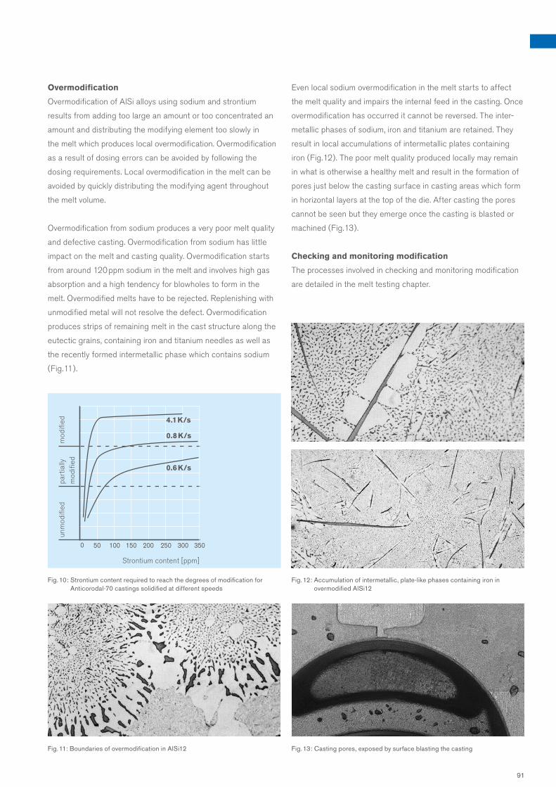
Overmodification
Overmodification of AlSi alloys using sodium and strontium
results from adding too large an amount or too concentrated an
amount and distributing the modifying element too slowly in
the melt which produces local overmodification. Overmodification
as a result of dosing errors can be avoided by following the
dosing requirements. Local overmodification in the melt can be
avoided by quickly distributing the modifying agent throughout
the melt volume.
Overmodification from sodium produces a very poor melt quality
and defective casting. Overmodification from sodium has little
impact on the melt and casting quality. Overmodification starts
from around 120 ppm sodium in the melt and involves high gas
absorption and a high tendency for blowholes to form in the
melt. Overmodified melts have to be rejected. Replenishing with
unmodified metal will not resolve the defect. Overmodification
produces strips of remaining melt in the cast structure along the
eutectic grains, containing iron and titanium needles as well as
the recently formed intermetallic phase which contains sodium
( Fig. 11 ).
Even local sodium overmodification in the melt starts to affect
the melt quality and impairs the internal feed in the casting. Once
overmodification has occurred it cannot be reversed. The inter-
metallic phases of sodium, iron and titanium are retained. They
result in local accumulations of intermetallic plates containing
iron ( Fig. 12 ). The poor melt quality produced locally may remain
in what is otherwise a healthy melt and result in the formation of
pores just below the casting surface in casting areas which form
in horizontal layers at the top of the die. After casting the pores
cannot be seen but they emerge once the casting is blasted or
machined ( Fig. 13 ).
Checking and monitoring modification
The processes involved in checking and monitoring modification
are detailed in the melt testing chapter.
Fig. 11: Boundaries of overmodification in AlSi12 Fig. 13: Casting pores, exposed by surface blasting the casting
Fig. 12: Accumulation of intermetallic, plate-like phases containing iron in overmodified AlSi12
Fig. 10: Strontium content required to reach the degrees of modification for Anticorodal-70 castings solidified at different speeds
Strontium content [ppm]
unm
odifi
ed
4.1 K/s
0.8 K/s
0.6 K/s
part
ially
m
odifi
edm
odifi
ed
91

Improper actions during the production and transport of melts
reduce the melt quality. Casting defects such as entrapped oxides,
gas porosity, shrinkage porosity and macro blowholes can often
be explained by such actions.
Sources of defects include:
1. Melting down too slowly
2. Replenishing with cold metal
3. Touching the flame with thin-walled returns
4. High temperature of melt
5. Inappropriate furnace maintenance
6. Poor furnace maintenance
7. Reacting with the crucible
8. Incorrect melt processing
9. Turbulent transport of melt
1. If ingots and returns are melted down too slowly, the
plastic phase lasts too long. The oxides of aluminium and
the alloy elements produced in such conditions cannot be cleanly
separated from what has already melted, most remains in the
melt and forms oxide skin cocoons in the melt ( Fig. 1 ). The melt-
ing loss increases significantly. The plastic state should therefore
be avoided. The pasty phase lasts for relatively long periods in
overfilled furnaces where use is not adapted to the melt
capacity. This also applies to electrically resistance-heated cast-
ing furnaces which are only designed as holding furnaces.
Causes of poor melt quality which result in casting defects
Depending on the alloy’s “segregation factor”, plate-shaped
crystals containing iron may also form and interrupt the homo-
geneous cast structure ( Fig. 2 ). They upset the magnetic flux in
the cast structure. The lines of force are deflected at the plate
edges and form peaks in tension, which greatly reduce the
elongation and result in early micro-cracks if the casting is
subject to dynamic loading. The solid solution plates containing
iron also prevent internal feeding in the casting.
2. Replenishing with cold ingots and returns results in
local supercooling in the melt as a result of which oxide
pipes in the ingots and returns do not separate perfectly from the
melt. Segregations occur and manganese aids the precipitation
of hard crystals. Fissured to compact, hexagonal AlFeMnSi crys-
tals 10 – 100 µm in size form in alloys with a higher Fe content.
The micro hardness of these crystals is 200 – 750 HV ( Fig. 3 ), or
more for compact crystals.
3. Small scaly returns oxidise in a lively manner if they
come into contact with the melt flame. The oxide skins
formed in the process accumulate like balls ( Fig. 4 ). Oxides
in this closed form remain stubbornly bound internally to the melt.
The oxides can only be removed from the melt once the oxide
skin can be torn off through the addition of melt fluxes. The salts
are added as required by the circumstances in the form of fine,
or preferably coarse, granulate. If the machining chips or spar-
kling high pressure die casting content cannot be melted down in
appropriate furnaces, this task should be assigned to a refinery.
4. Temperatures in excess of 800 °C greatly damage the
aluminium melt. The absorption of hydrogen and formation of
oxide increase quickly at high temperatures, especially if the
air humidity in the vicinity of the melt furnace or transport crucible
is high. Because of the change in solubility of hydrogen when
moving from a liquid to a solid state, undesirable gas bubbles
form in the casting, mainly on the oxides acting as nuclei ( Fig. 2
in refinement chapter ). Containers and dies in direct contact
Fig. 2: Precipitated AlFeSi plates Fig. 3: Compact AlMnFeSi precipitation
Fig. 1: Oxide skin cocoons
92

with the melt must be heated up separately, to melt temperature
wherever possible. Delays should be avoided in transporting and
processing the melt. If using dressed tools and insulation, even
when decanting, the melt does not have to be heated so much.
Reactions with refractory materials are also less likely.
5. Refractory furnace cladding not suitable for alumin-
ium melts will react with the melt. The reaction products
contaminate the melt ( Fig. 5 ); the furnace liner is mineralised.
The amphoteric behaviour of aluminium should be taken into
account when selecting refractory materials. Materials with an
Al2O3 content of more than 85 % have proven their value in such
circumstances. Preference should also be given to particularly
dense refractory materials, especially if they come into contact
with AlMgSi melts, as virtually no infiltration will then occur.
6. Furnaces which are not kept clean allow oxides to
crystallise ( Fig. 6 ) and deposits to form e. g, from corundum
( Al2O3 ), periclase ( MgO ), spinel ( MgAl2O4 ), oxide hydrate
( OAlOH ), zirconium oxide ( ZrO2 ) or quartz ( SiO2 ). Melt tempera-
tures of 700 °C in the furnace with a normal supply of air will
after 25 hours result in the formation of corundum nuclei, at
800 °C this will happen after just 7 hours. These hard inclusions
are only avoided through a shorter refinement interval.
7. In order to rule out the possibility of reactions be-
tween the melt/holding crucible and aluminium melt,
we would recommend annealing it for several hours
at 800 °C before use. This applies equally to clay-graphite
crucibles and silicon-carbide crucibles. The reaction products
formed in the melt during improper handling result in what are
known as “black inclusions” in the cast structure.
Fig. 4: Accumulated oxide skins, ball of oxide Fig. 6: Crystallised oxides
Fig. 5: Reaction bubble with oxide skin cluster
8. Over-lively bath movement when degassing the melt
must be avoided. The bubbles of refinement gas rising to the
surface must not draw the oxide-rich surface of the bath into the
melt. Melts may however also be ruined by improper grain refine-
ment and modification, as is reported in the chapters on grain
refinement and modification.
9. When transferring aluminium melts, turbulence must
not develop in the pouring stream. It must be a laminar and
closed stream. Free falling should be avoided through the use
of suitable channel or pipe systems. Turbulent metal flows don’t
just entrain air with them but also the constantly reforming oxide
pipe of the melt. The 80 mbar density sample demonstrates how
improper transfer impairs the quality of the melt. A melt with a
density of 2.65 g/cm3 was poured from the furnace straight into
a crucible; the height of the drop was 2.10 m. After this turbulent
transfer, the melt in the crucible had a density of just 2.43 g/cm3.
After using a calculated pipe system to decant, the melt quality in
the crucible rose again to a density of 2.55 g/cm3.
93

Melt impurities
All the mistakes which can be made when melting down ingots and returns, transport-
ing and decanting melts and processing melts lead to a poor melt quality as a result of
oxides and a high hydrogen content. Refer to section: Causes of poor melt quality which
result in casting defects.
A distinction should be made between three kinds of oxides ( Fig. 1 ): compact oxide,
flaked oxide, oxide skins. Compact and flaked oxides can be removed from the alumin-
ium melt with relative ease; this is not the case with oxide skins. These are microoxides
which only become apparent on the microsection and float in the melt in their various
sizes.
Hydrogen occurs in aluminium casting alloy melts in two forms: as hydrogen atomically
dissolved in the melt and as a molecularly precipitated gas, usually in close association
with microoxides ( Fig. 2 ).
Process for refining melt
Coarse oxides are generally easier to remove from the melt and this can be done using
filters or by flushing. A salt mixture of pressed gas flushing tablets is used to refine
melts in individual applications. The tablets are placed on the base of the crucible using
a dry, dressed perforated bell. They release nitrogen when in a nuclear state and release
no smoke or odours. 1 kg tablets used at melt temperatures of around 720 °C will pro-
duce between 150 and 350 l of nitrogen.
Ceramic foam filters have proved to be a good solution especially in high pressure die
casting foundries which remelt in a closed loop. The filter captures all kinds of oxides
( Fig. 3 ) and therefore also the majority of the hydrogen. After use the filter has to be
heated continually to prevent the melt solidifying in the filter’s pore cells. A quadratic
ceramic foam filter with an edge length of 450 mm can refine around 20 t of melt. The
same ceramic foam filters but of a smaller size are used by casters in the tip system with
sand and gravity die casting.
The molecularly precipitated hydrogen remains stubbornly in the melt if it has attached
itself to microoxides. Removing this hydrogen means removing all the microoxides.
Melt processing tablets containing oxide-binding salts are used for this purpose.
Fig. 1: Different types of oxide ( from top ): compact oxide; flaky oxide; oxide skin; oxide skin with gas bubble
Refining aluminium casting alloy melts
Fig. 2: Accumulation of oxide skins with gas bubble inclusions
94

with rotor treatment
0.0910.087
0.2180.216
0.087
untreated treated
Hyd
roge
n co
nten
t [m
l/10
0 g
]
Fig. 4: Effect of a rotor in the continuous refinement process
without rotor treatment
Melt refining with a gas flushing lance can be used with inert
gases such as argon and nitrogen, or in combination with suitable
degas treatment with reactive gases such as chlorine. Gas mix-
tures of inert and reactive gases are also used here. It is impor-
tant that the gases are added to the melt in a finely distributed
form. The end of the lance must therefore feature a fine porosity
head. The gas treatment process takes a very long time and
cools the melt a lot.
Refining melts using negative pressure and/or vacuum degassing
involves no magnesium or strontium burnout and keeps the loss
of sodium within limits for modified melts. Reducing pressure to
1 – 3 mbar has the effect of greatly reducing the partial hydro-
gen pressure on the surface of the bath such that the dissolved
hydrogen escapes from the melt very quickly. The low pressure
on the surface of the bath is not present in the melt because of
metallostatic pressure. The pressure at 10 cm below the surface
of the bath is 25 mbar. The melt must therefore be circulated
with a gas flushing lance to ensure that all the metal comes into
contact with the surface of the bath. Some of the microoxides
are also removed. The negative pressure equipment is frequently
heated because melt processing may take 5 – 30 minutes.
The inert gases argon or nitrogen also cause dissolved hydrogen
to be physically removed from the melt through the reduction in
partial pressure.
The combined removal of oxide and hydrogen from melts using
gas rotors is now the most effective, environmentally sound and
fastest method. This process involves a graphite rotor adapted
to the crucible size drawing the inert gases as low as possible in
the full melt crucible. The high level of rotation causes the rotor to
pulverise the gas flow and at the same time distribute the rising
bubbles of gas over the crucible width.
The rule of thumb for effective refinement is:
speed of rotor rotation = 500 – 600 rpm
treatment time = 6 – 10 minutes
with 7 – 10 I/hour of argon or nitrogen for 600 kg of melt.
If argon or nitrogen is being used, the waterfree variant ( Quality
5.3 ) must be ensured. The level of melt refinement achievable is
greatly affected by the rotor and gas quality. Reduced treatment
times can be used such that the crucible does not have to be
heated. The melt can also be refined in a continuous process with
the rotor ( Fig. 4 ).
Gravity die casters also use forming gas, comprising 70 % argon
and 30 % hydrogen, as the flushing gas if the casting needs a finely
distributed hydrogen porosity in order to avoid coarse blowholes
and shrinkage pores. Specifically added nano-structured oxides
also act in the same way. As there are so many nuclei, they bring
about the precipitation of fine hydrogen gas pores.
Refining modified melts
Only short-term gas flushing treatment is permitted to prevent
sodium and strontium burnout in modified melts. Tabletted fluxes
emitting only nitrogen have proven a good solution; modified
melts refined using ceramic foam filters are only sufficiently
refined of oxides. The best way of refining modified melts cur-
rently in use is a process involving an effective gas rotor, see the
chapter on modification. The negative pressure degassing does
however produce very low gas contents for modified melts.
Fig. 3: Foam ceramic filter; black = ceramic flowing from left to right
95

Melt testing
The melt quality must be perfect for an immaculate casting.
The density index, nucleation state, degree of modification of
AISi alloys and gas content provide evidence of the melt quality.
The density index can be calculated using the negative pressure
density measurement and the nucleation state and degree of
modification from the thermal analysis. The gas content is mea-
sured using the aluminium melt tester. These tests can be used
for every casting to quickly ascertain the melt quality needed for
a healthy casting.
Calculating negative pressure density
This test method involves a melt of around 80 g being solidified
in a dressed iron crucible in a vacuum chamber with negative
pressure of 80 mbar. The time it takes the sample to solidify
depends on the alloy but will be around 4 minutes. A sample from
the same melt is solidified in parallel at atmospheric pressure.
The density of both samples is calculated using Archimedes‘ prin-
ciple. The impact of pressure on the microstructure of the density
sample can be clearly seen in Fig. 1 using a melt of Anticoro-
dal-70 dv with strontium modification.
The sample which solidified under atmospheric pressure has a
considerably more dense cast structure and therefore a greater
density of 2.62 g/cm3. On the other hand the sample which
solidified at less than 80 mbar displays a relaxed, porous micro-
structure and a lower density of 2.35 g/cm3. The density index
is 10.3 % and is calculated using this formula:
Experience has shown that the following minimum
values are needed for the 80-mbar pressure density for
the alloy groups if you are to obtain a good casting:
AISi alloys 2.55 g/cm3
AICu alloys 2.65 g/cm3
AIMg alloys 2.55 g/cm3
AIZnSi alloys 2.75 g/cm3
AISiCu alloys 2.65 g/cm3
The density index of 10.3 % is too high to pour a casting with a
healthy microstructure. Every casting has its own optimum density
index. Experience shows that the average density index should not
exceed 4 %. Some challenging castings require higher 80-mbar
negative pressure density values for a healthy casting. Fig. 1: Cut-open samples from a negative pressure density test using Anticorodal-70 dv
Fig. 2 shows the dependency of the pore volume in the casting
on the negative pressure density. This also takes account of the
solidification time.
The influence of solidification time on pore volume in the cast
structure for different negative pressure densities can be seen in
Fig. 3. This shows that at a very low negative pressure density,
a high speed of solidification has virtually no impact on producing
a lower pore volume in the cast structure.
Thermal analysis
Testing the melt‘s negative pressure density alone is not enough
to ensure that a healthy, dense casting is being poured.
A good low density index provides no clues as to the growth of
aluminium solid solutions, i.e. dendrites. Despite having a good
density index, it is possible for dendrites to be growing too fast
and for this to result in leaks in the thin wall thicknesses of the
casting. The thermal analysis provides information on the nuclear
state of the melt, especially growth of the primary crystals, the
dendrites.
Monitoring grain refinement
The progression of primary crystals provides evidence of the
grain size which the computer in the thermal analysis device
calls the nucleation state (KF), Fig. 4 shows flat progression of
primary crystals with a high nucleation state of KF = 13.5.
The primary crystals in the second diagram in the same figure
have a much more distinct progression and a lower nucleation
state of KF = 9.4.
In order to avoid volume deficits in the casting, the nucleation
state KF should be above 9.
The maximum grain refinement values are recorded in the table
below:
Sf-13, Sf-20 = 14.1
Sf-30 = 14.9
Uf-90 = 13.4
Ac-70, Ac-72, Ac-78 dv = 15.7
DI [%] = ρ1000 mbar – ρ80 mbar × 100 ρ1000 mbar
96

Since the nucleation state and degree of modification are contradictory, you should not
aim for the highest possible nucleation state to ensure good modification of the casting.
There is no point in adding more grain refiner to the melt if the maximum grain refine-
ment values stated have already been reached. Not only is this a waste of money, but it
will impair the modification, the microstructure and therefore the mechanical properties.
The nucleation states listed are values from the computer in the EMTEC thermal analy-
sis equipment, most commonly found in aluminium foundries. A guideline is entered in
the computer for classification of grain size and this may differ when using other types
of equipment; e. g. a nucleation state of KF 9 has a grain surface of 2.5 mm2.
Monitoring modification
A thermal analysis is a good way of monitoring Na modification in AlSi melts. The
analysis measures supercooling, i.e. the difference in temperature between the eutectic
temperature of the unmodified melt and the eutectic temperature of the modified melt.
This difference in temperature is known as depression. We have found that a depression
of between 4 and 6 K ensures good modification. Due to the slower solidification, sand
castings need higher depressions than gravity die castings. However the depression for
sand castings with wall thicknesses of more than 40 mm should not exceed 5 K as a
porous cast structure may otherwise result. As mentioned in the section on grain refine-
ment, depression, also known as the degree of modification, is the opposite of nucle-
ation state. A very high level of modification reduces the nucleation state which must not
fall below 9 or the initial signs of micro and macro blowholes may result.
Aluminium melt tester
Using an aluminium melt tester involves solidifying around 80 g of melt at an increas-
ingly negative pressure in a vacuum flask with sight glass. The emergence of the first
bubbles on the surface of the sample is recorded in modern equipment with a camera.
Pressure and temperature are recorded and the gas and/or hydrogen content of the
melt calculated from these figures. Sand casters and gravity die casters in particular use
the aluminium melt tester to set the hydrogen level which the casting needs for a
healthy cast structure.
Melt testing using flow through filter
The flow volume or the time it takes for a particular volume to pass through a filter can
be used to test casting alloys. A coarse filter, such as “Qualiflash”, will only provide
insufficiently accurate quality levels. A fine filter with pressure support on the melt
surface, as is offered by e.g. “ PoDFA”, records a grain refinement nucleus as an impurity
impacting on throughflow and is not therefore commonly used.
Fig. 4: Print-outs from thermal analysis
Density at 80 mbar [g/cm3]
t E = 350 st E = 100 st E = 40 s
Solidification time t E
Solidification time [s]
Por
e vo
lum
e [%
]
1.99 g/cm3. Sr
2.28 g/cm3. Sr
2.42 g/cm3. Sr
2.69 g/cm3. Sr
2.59 g/cm3. Na
Fig. 2: Dependency of pore volume in casting structure on negative pressure density at 80 mbar
Fig. 3: Dependency of pore volume in cast structure on solidification time for melts with different negative pressure densities
Por
e vo
lum
e [%
]
97

temperature falls. If the melt is rapidly cooled from a high solution
heat treatment temperature by quenching, the structural constitu-
ent dissolved in the solid solution cannot be precipitated. The
solid solution supersaturated in this way tries to precipitate this
constituent again during ageing and to approach an equilibrium.
Artificial ageing can be repeated, starting with solution heat
treatment for a shorter period of 4 hours. If repeated several
times, there is a risk of the grains coarsening. If this happens,
the mechanical properties of the casting become sub-optimum.
Solution heat treatment
Solution heat treatment causes a greater number of ageing con-
stituents of the alloy to dissolve than is the case with an equilib-
rium at room temperature. The eutectic silicon is also cast in AlSi
alloys. Temperature and time must be coordinated and the size of
structural constituents determined by the casting‘s solidification
time must be taken into account.
The annealing temperature should be as high as possible
because solubility and speed of diffusion increase sharply with
temperature. In practice it is around 10 – 15 °C below the melt
temperature for low-melting structural constituents. The tempera-
ture must be kept at a level of at least ± 5 °C precisely.
The table contains approximate values for the heat treatment of
our casting alloys.
The temperature should be slowly raised during solution heat
treatment to remove the grain precipitation by means of diffusion.
Otherwise there is a risk of the grains starting to melt. We
would therefore recommend stepped annealing for thick-walled
sand castings made from Alufont: 4 – 6 h at 490 °C, followed by
8 – 12 h at 520 °C. The annealing period is determined by the wall
thicknesses of the casting, casting method and solution heat
treatment temperature. The annealing time is calculated from the
point when the ultimate temperature is reached.
The heating-up time is not taken into account.
Artificial ageingHeat treatment for special purposes Self-ageing
Preface
The mechanical properties of most aluminium casting alloys can
be greatly enhanced as required by the caster using heat treat-
ment. The type of process used is determined by the intended
effect and depends on casting alloy, casting method and solidifi-
cation time.
The following casting states can be achieved from the most
important type of heat treatment, artificial ageing:
artificially aged ( T6 )
partially aged ( T64 )
naturally aged ( T4 )
This treatment always consists of solution heat treatment and
quenching; the subsequent ageing process then either takes
place in heat or at room temperature depending on the desired
state. A distinction is made between full and partial ageing de-
pending on the ageing temperature and time chosen. No further
heat treatment is required after solution heat treatment and
quenching when using natural ageing. The castings age at room
temperature.
Other heat treatment methods for castings include:
annealing
stress-relief annealing
stabilising
artificial ageing
overageing
Self-ageing alloys are alloys where the composition is con-
sciously chosen so that simply storing the castings without any
kind of heat treatment will result in a considerable increase in
hardness and strength.
Artificial ageing
Artificial ageing normally comprises three stages of treatment:
• solution heat treatment
• quenching
• artificial, partial ageing or natural ageing
Precipitation occurs in the aluminium solid solution when ageing.
This may take place when the aluminium solid solution displays
decreasing solubility for one particular alloy component as the
98

AlloyChemical denomination
Solution heat Solution heat Quenching Ageing Ageing treatment treatment water temperature duration temperature duration temperature State °C h °C °C h
Previous EN Denomination denomination
F as-cast state as-cast state, production state
O annealed soft annealed g
T1 self-aged naturally aged rl
T1 controlled cooling after casting
T4 naturally aged solution heat treated, quenched, naturally aged ka
T5 stabilised overaged without solution heat treatment st
T5 quenched artificially aged artificial aged without solution heat treatment aw
T6 Artificially aged solution heat treated, quenched and fully artificial aged wa
T64 partially aged solution heat treated, quenched and not fully artificial aged, underaged ta
T7 overaged solution heat treated, quenched and overaged, stabilised state ü
Anticorodal -04 AlSi0.5Mg T6 520 – 530 6 – 8 20 180 – 190 6 – 8
T7 520 – 530 6 – 8 20 220 – 240 4 – 6
Anticorodal -50 AlSi5Mg T6 520 – 535 4 – 8 20 155 – 160 7 – 9
T4 520 – 535 4 – 8 20 15 – 30 120
Anticorodal-70 AlSi7Mg0.3 T6 520 – 545 4 – 10 20 155 – 165 6 – 8
T64 520 – 545 4 – 10 20 150 – 160 2 – 3
Anticorodal-78dv AlSi7Mg0.3 T6 520 – 545 4 – 20 20 145 – 160 2 – 15
Anticorodal-71 AlSi7Mg0.3 - E T6 520 – 545 4 – 8 20 155 – 165 6 – 8
T7 520 – 545 4 – 8 20 200 – 230 6 – 8
Anticorodal-72 AlSi7Mg0.6 T6 520 – 545 4 – 10 20 155 – 165 6 – 8
T64 520 – 545 4 – 10 20 150 – 160 2 – 3
Silafont-30 AlSi9Mg T6 520 – 535 6 – 10 20 160 – 170 6 – 8
T5 – – Air 210 – 230 6 – 8
Silafont-36 AlSi10MnMg T6 480 – 490 2 – 5 20/Air 155 – 170 2 – 6
T7 480 – 490 1 – 5 20/Air 190 – 230 1 – 3
T4 480 – 490 2 – 5 20/Air 15 – 30 120
T5 – – 20 155 – 190 2 – 5
Silafont-38 AlSi9MnMgZn T6 470 – 490 1 – 3 20/Air 155 – 190 1 – 3
T6 470 – 490 1 – 3 20/Air 155– 210 1 – 3
Silafont-13 AlSi11 O 520 – 530 6 – 8 20 – –
Silafont-20 AlSi11Mg T6 520 – 535 6 – 10 20 130 – 170 6 – 8
T5 – – Air 210 – 230 5 – 8
Silafont -70 AlSi12CuNiMg T6 520 – 530 5 – 10 20 – 80 165 – 185 5 – 8
T5 – – Air 210 – 220 10 – 12
Castaman-35 AlSi10MnMg T6 480 – 490 2 – 5 20/Air 155 – 170 2 – 6
Castasil-21 AlSi9Sr O 345 – 355 1 – 2 Air – –
Alufont-47 AlCu4TiMg T4 520 – 530 8 – 16 20 – 80 15 – 30 120
Alufont-48 AlCu4TiMgAg T6 525 – 530 8 – 16 20 – 80 160 – 180 6 – 7
Alufont-52 AlCu4Ti T6 525 – 535 8 – 16 20 – 50 160 – 175 6 – 7
T64 525 – 535 8 – 10 20 – 50 135 – 145 6 – 7
Alufont-60 AlCu5NiCoSbZr T7 535 – 545 10 – 15 80 210 – 220 12 – 16
O 345 – 355 5 – 10 Air
Thermodur-73 AlSi11Cu2Ni2Mg2Mn T5 – – Air 210 – 270 10 – 12
99

The finer the cast structure, the faster the ageing constituents
dissolve. The following applies to AISi alloys:
• shorter time for gravity die casting, thin-walled sand casting and
higher solution heat treatment temperature
• longer time for sand casting, thick-walled gravity die casting
and lower solution heat treatment temperature.
Since the castings still only display low strength levels at a high
annealing temperature, complicated castings must be stacked
such that distortion from their own weight is kept low. Special
annealing tools are needed in a few cases.
Depending on casting technique, high pressure die cast-
ings are harder to put through solution heat treatment than sand
castings or gravity die castings due to the differing levels of
gas bubbles included in the cast structure. Thanks to very fine
grained solidification resulting from the high speed of cooling,
solution heat treatment can deliver good results with a shorter
time and lower temperature ( 480 – 490 °C ).
Fig. 1: Influence of artificial ageing temperature on properties of Silafont-30, AlSi9Mg, sand casting. Ageing time of 7 hours each, magnesium content of 0.28 %
Fig. 2: Influence of ageing temperature on properties of Silafont-30 dv, AlSi9Mg, gravity die casting containing 0.28 % and 0.50 % magnesium. Ageing time of 7 hours each
Fig. 3: Influence of ageing temperature on properties of Alufont-52, AlCu4Ti, sand casting. Ageing time of 7 hours each
Fig. 4: Influence of ageing temperature on properties of Alufont-52, AlCu4Ti, gravity die casting. Ageing time of 7 hours each
0.2
% y
ield
tens
ile s
tren
gth
R p0
.2
nd u
ltim
ate
tens
ile s
tren
gth
R m
[MP
a]
0.2
% y
ield
tens
ile s
tren
gth
R p0
.2
and
ultim
ate
tens
ile s
tren
gth
R m
[MP
a]
0.2
% y
ield
tens
ile s
tren
gth
R p0
.2
and
ultim
ate
tens
ile s
tren
gth
R m
[MP
a]
0.2
% y
ield
tens
ile s
tren
gth
R p0
.2
nd u
ltim
ate
tens
ile s
tren
gth
R m
[MP
a]
Elo
ngat
ion
A [%
]B
rinel
l har
dnes
s H
BW
Elo
ngat
ion
A [%
]B
rinel
l har
dnes
s H
BW
Elo
ngat
ion
A [%
]B
rinel
l har
dnes
s H
BW
Elo
ngat
ion
A [%
]B
rinel
l har
dnes
s H
BW
HBW
R m
R p0.2
A
Ageing temperature [°C] Ageing temperature [°C]
Ageing temperature [°C]Ageing temperature [°C]
HBW
HBW
R m
R m
R p0.2
R p0.2
A
A
= 0.50 % Mg= 0.28 % Mg
R m
HBW
R p0.2
A
R m
HBW
R p0.2
A
100
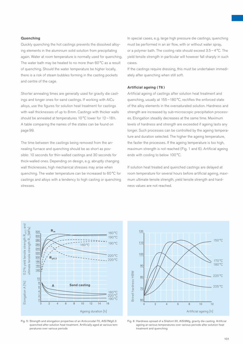
Quenching
Quickly quenching the hot castings prevents the dissolved alloy-
ing elements in the aluminium solid solution from precipitating
again. Water at room temperature is normally used for quenching.
The water bath may be heated to no more than 60 °C as a result
of quenching. Should the water temperature be higher locally,
there is a risk of steam bubbles forming in the casting pockets
and centre of the cage.
Shorter annealing times are generally used for gravity die cast-
ings and longer ones for sand castings. If working with AlCu
alloys, use the figures for solution heat treatment for castings
with wall thicknesses of up to 8 mm. Castings with thicker walls
should be annealed at temperatures 10 °C lower for 12 – 18 h.
A table comparing the names of the states can be found on
page 99.
The time between the castings being removed from the an-
nealing furnace and quenching should be as short as pos-
sible: 10 seconds for thin-walled castings and 30 seconds for
thick-walled ones. Depending on design, e. g. abruptly changing
wall thicknesses, high mechanical stresses may arise when
quenching. The water temperature can be increased to 60 °C for
castings and alloys with a tendency to high casting or quenching
stresses.
In special cases, e. g. large high pressure die castings, quenching
must be performed in an air flow, with or without water spray,
or a polymer bath. The cooling rate should exceed 3.5 – 4 °C. The
yield tensile strength in particular will however fall sharply in such
cases.
If the castings require dressing, this must be undertaken immedi-
ately after quenching when still soft.
Artificial ageing ( T6 )
Artificial ageing of castings after solution heat treatment and
quenching, usually at 155 – 180 °C, rectifies the enforced state
of the alloy elements in the oversaturated solution. Hardness and
strength are increased by sub-microscopic precipitation process-
es. Elongation steadily decreases at the same time. Maximum
levels of hardness and strength are exceeded if ageing lasts any
longer. Such processes can be controlled by the ageing tempera-
ture and duration selected. The higher the ageing temperature,
the faster the processes. If the ageing temperature is too high,
maximum strength is not reached ( Fig. 1 and 6 ). Artificial ageing
ends with cooling to below 100 °C.
If solution heat treated and quenched castings are delayed at
room temperature for several hours before artificial ageing, maxi-
mum ultimate tensile strength, yield tensile strength and hard-
ness values are not reached.
Fig. 5: Strength and elongation properties of an Anticorodal-70, AlSi7Mg0.3 quenched after solution heat treatment. Artificially aged at various tem-peratures over various periods
Fig. 6: Hardness spread of a Silafont-30, AlSi9Mg, gravity die casting. Artificial ageing at various temperatures over various periods after solution heat treatment and quenching
Elo
ngat
ion
A [%
]0
.2 %
yie
ld te
nsile
str
engt
h R
p0.2
and
ul
timat
e te
nsile
str
engt
h R
m [M
Pa]
160 °C190 °C
190 °C160 °C
220 °C220 °C
160 °C220 °C190 °C
R m
R p0.2
A Sand casting
Ageing duration [h]
Brin
ell h
ardn
ess
HB
W
Artificial ageing [h]
150 °C
170 °C180 °C
220 °C
225 °C
101

Partial ageing ( T64 )
Partial ageing is artificial ageing carried out in a shorter time or
at a lower temperature after solution heat treatment. It aims
to deliver higher elongation without maximum strength and hard-
ness values.
Natural ageing ( T4 )
Castings from heat-treatable alloys, e. g. Anticorodal-50 and
Alufont-47, but also high pressure die casting alloy Silafont-36,
are stored at room temperature for around 6 days after solution
heat treatment and quenching. This increases strength levels
and delivers very good elongation values.
Heat treatment for special purposes
Special properties in the castings for special applications can be
achieved through other specific forms of heat treatment.
Annealing ( O )
If castings are annealed for several hours at 350 – 450 °C and
cooled in the furnace, formability is improved through the cast-
ing of silicon crystals. Such castings can be cold formed using
riveting and flanging. Elongation and fatigue strength are also
improved.
Fig. 7: Influence of ageing temperature on the properties of Anticorodal-04, AlSi0.5Mg. Ageing time of 7 hours each
Fig. 8: Influence of ageing temperature on the properties of Anticorodal-71, AlSiMg0.3. Ageing time of 7 hours each
Fig. 10: Mechanical properties on gravity die casting test pieces with 16 mm Ø made from self-ageing alloy Castadur-90, AlZn10Si8Mg in days after casting
Fig. 9: Mechanical properties on French gravity die casting test pieces made from self-ageing alloy Castadur-30, AlZn3Mg3Cr in days after casting
0.2
% y
ield
tens
ile s
tren
gth
R p0
.2
and
ultim
ate
tens
ile s
tren
gth
R m
[M
Pa]
0.2
% y
ield
tens
ile s
tren
gth
R p0
.2
and
ultim
ate
tens
ile s
tren
gth
R m
[M
Pa]
0.2
% y
ield
tens
ile s
tren
gth
R p0
.2
and
ultim
ate
tens
ile s
tren
gth
R m
[MP
a]
Ele
ctric
al c
ondu
ctiv
ity
χ[m
/Ω ×
mm
2]
Ele
ctric
al c
ondu
ctiv
ity
χ[m
/Ω ×
mm
2]
Auslagerungstemperatur [°C]Ageing temperature [°C]
Ageing temperature [days]
R m
HBW
R p0.2
A
χ
R m
HBW
R p0.2
A
χ
R m
R p0.2
A
Elo
ngat
ion
A [%
]
Elo
ngat
ion
A [%
]
Elo
ngat
ion
A [%
]
Brin
ell h
ardn
ess
HB
W
Brin
ell h
ardn
ess
HB
W
0.2
% y
ield
tens
ile s
tren
gth
R p0
.2
and
ultim
ate
tens
ile s
tren
gth
R m
[MP
a]
Ageing temperature [days]
Elo
ngat
ion
A [%
]
R m
R p0.2
A
102

The near eutectic alloy Silafont-13 is annealed at 520 – 530 °C for around 6 – 8 hours, high pressure
die casting alloys for shorter periods at a lower temperature.
Stress-relief annealing ( T5 )
When solidifying castings, internal stresses occur as a result of different wall thicknesses, differ-
ent speeds of cooling and the fact that various areas of the casting prevent shrinkage. In order to
prevent the castings from distorting during operation, they can be annealed to be free of stresses
before final machining. This annealing treatment is undertaken at 200 – 300 °C for several hours.
The higher the temperature and the longer the treatment, the more effective it is. This treatment is
undertaken on castings which require very accurate dimensions.
Designs with welded castings, including high pressure die castings, are annealed to remove the
shrinkage stresses produced during welding at considerably greater speed.
Stabilising ( T5 )
Precipitation processes occur in all castings at higher operating temperatures and result in tiny
changes in volume. This can be prevented in precision parts ( pistons, optical modules and
precision engineering ) by undertaking stabilising annealing. The annealing temperature depends on
the subsequent operating temperature. The annealing temperature is approx. 200 – 300 °C,
rarely any lower.
Artificial ageing ( T5 )
This form of treatment is ageing without solution heat treatment. Artificial ageing can be used to
improve the strength and hardness of simple gravity die castings or high pressure die castings
made from heat-treatable alloys. A better result can be achieved if the castings are quenched in
cold water immediately after being removed from the casting die. The temperature of the casting
must be in excess of 350 °C when plunging. Huge scatter should be expected in the various wall
thicknesses of the casting.
Overageing ( T7 )
After solution heat treatment and quenching, artificial ageing is undertaken at 200 – 240 °C.
The aim of this process is higher electrical conductivity and elongation with lower strength in the
alloys Anticorodal-04 and Anticorodal-71 ( Fig. 7 and 8 ).
Self-ageing ( T1 )
Very good mechanical properties can be achieved in special alloys with a high zinc content, such
as Unifont-90 and Unifont-94, Castadur-50, AlZn5Mg or Castadur-30, AlZn3Mg3 without heat
treatment. This process is known as self-ageing and must not be confused with cold ageing which
comes before solution heat treatment with quenching. Self-ageing starts when the castings are
removed from the mould. The increase in strength is normally complete 8 days later ( Fig. 9 and 10 ).
Self-ageing alloys are used to cut heat treatment costs or for technical reasons, e. g. lower distortion
level needed or due to the huge size of a casting.
103

Heat treatment for high pressure die castings
The mechanical properties of even high pressure die casting alloy
Silafont-36 can be significantly improved through heat treat-
ment. Unlike the case with sand and gravity die castings, here the
high pressure die method determines the possible kind of heat
treatment process. The crucial factor is whether solution heat
treatment is even possible. If solution heat treatment is required,
high pressure die castings have to be produced under special
production conditions, such as enforced ventilation of the mould,
controlled application of mould release agent and controlled
metal flow. Gas or air inclusions in the surface areas of castings
cast in the conventional way lead to the formation of blisters on
the casting surface.
When working with large high pressure die castings in particular,
it should be noted that the castings will distort if not correctly
stored in the furnace and if suitable techniques are not used
when plunging in the water bath.
Heat treatment without solution heat treatment
Annealing ( O )
This form of heat treatment undertaken at 380 °C for 30 – 60
minutes reduces stresses in the rapidly solidified high pressure
die casting microstructure and therefore increases elongation.
This increased formability allows the cast design elements to be
riveted and flanged, even when working with Silafont-36 with a
higher magnesium content.
Artificial ageing ( T5 )
The yield tensile strength can be raised slightly using this sim-
plified heat treatment process without any risk of the casting
distorting. The risk of this happening during quenching and the
amount of subsequent dressing work are also considerably lower
than for heat treatment with solution heat treatment.
Once removed from the moulds, the castings are immediately
quenched in the water bath and artificially aged. The effective-
ness of artificial ageing is greatly determined by the temper-
ature in the casting when removing from the mould and more
precisely when plunging in the water. The higher this temperature
( around 400 °C ), the greater the potential for ageing during
artificial ageing. Raising the yield tensile strength any further
requires a delay of more than 10 hours before ageing at 190 °C
for 120 minutes.
Heat treatments with solution heat treatment
Due to the fine-grained solidification of high pressure die cast-
ings, solution heat treatment can produce good results in a
shorter time and at a lower temperature ( 480 – 490 °C ) than in
gravity die castings. Due to the Silafont-36 material, use tem-
peratures of 520 – 535 °C.
Natural ageing ( T4 )
Amongst the various forms of heat treatment, natural ageing
produces castings with the greatest elongation. The castings
are solution heat treated, quenched and naturally aged for more
than 6 days at room temperature. The casting is first held at
the solution heat treatment temperature of 460 – 500 °C for
3 hours such that the elements soluble in the solid solution can
diffuse in it. At the same time, the eutectic silicon is cast, making
maximum elongation possible. Subsequent quenching in water
prevents the dissolved elements from precipitating. Most of
them remain in the solid solution matrix and only result in a small
increase in strength during natural ageing.
Artifically aged ( T6 )
Heat treatment following T6 involves complete heat treatment
with solution heat treatment (depending on the requirements
between 460 – 500 °C ), quenching in water and then artificial
ageing. Because of the high temperature used for solution heat
treatment, there is a risk of surface defects forming as the gas
pores previously embedded start to expand. Measures must also
be taken to prevent unwanted distortion when quenching the
castings in water. Only full artificial ageing at 160 – 250 °C results
in maximum alloy strength. Elongation produces values lower
than when in the as-cast state. A Silafont-36 with a magnesium
content of no less than 0.25 % should be used.
Overageing ( T7 )
If you start with fully aged state T6 and apply longer ageing times
or higher temperatures ( 235 °C / 90 minutes ), overaged state
T7 will result. The aim of this treatment is a thermally stable cast
structure with very good elongation and higher strength values
than in state T4, Silafont-36 with a Mg content of less than 0.20 %
produces the maximum elongation.
Quenching in air following solution heat treatment
In order to minimise high pressure die casting distortion, the cast-
ing is quenched in air rather than water after the solution heat
treatment. From metallurgical side it is necessary to obtain more
than 3 K/s in the temperature range between 500 and 350 °C.
A yield tensile strength of more than 120 MPa can only be
achieved with a magnesium content in excess of 0.30 %, if then
aged for 2 hours at a temperature of 170 °C. This is more than
30 % below the maximum attainable yield tensile strength.
104

Fatigue strength
Dependence on quality of the structure
The quality of the structure is affected by the choice of alloy, its
heat treatment, and in the case of AlSi alloys, the way the struc-
ture is formed. Fine distribution or avoidance of heterogeneous
phases, such as silicon and iron, is desirable (Fig. 1). The silicon
content lowers the fatigue strength of AlCu alloys, as does an
iron content exceeding 0.16 % in AlSi alloys. A coarse structure
and high grain boundary coating reduce the notch toughness
( K c ) and fatigue strength ( σ w ).
The casting process dictates the solidification and filling condi-
tions, which also have an impact on the occurrence of pores,
blowholes and oxides. A short solidification time results in a
finer structure and therefore a significant improvement in the
resistance to vibration. For example, a separately cast ingot of
tempered AlSiMG alloy that solidifies in 5 seconds can withstand
reversed bending stresses of σ bw = ± 100 MPa with a fatigue life
of n = 50 × 106 whilst with a sand casting with an approximately
5-minute solidification period ( 30 mm wall thickness ), this value
falls to σ bw = ± 30 MPa in order to achieve the same lifetime
without fracture.
Dependence on the surface quality
The term surface quality is defined as follows:
• the roughness of the surface as a result of the casting process
• casting defects such as heat cracks, stretcher strain marks and
imperfections introduced by the mould material
• notching through corrosion or extreme mechanical stresses
• surface coatings
Synthetic resin coatings and ground surfaces increase the
fatigue strength; hard surface layers, such as those that are
created with anodising and chroming processes, reduce it.
Dependence on the stress range
The vibration fatigue strength is critically dependent on the level
of stress ( compression, alternate loads and tensile loads ). The
maximum strength in the pulsating range ( r = 0.7 ) is always
higher than in the alternating range ( r = -1 ). The adjacent Smith
diagram is based on DIN 50 100 ( Fig. 2 ).
Note on the values for resistance to alternating stresses
The values for resistance to alternating stress in the chapter on
mechanical properties are values from tests in accordance with
DIN 50 113 or 50 142.
Note that in a casting in accordance with the criteria above,
the resistance to alternating stress values can be reduced to as
little as 25 % of the values given in the table if conditions are
unfavourable. The functional safety of castings should therefore
be subjected to dynamic component testing.
Fig. 1: Results from alternating bending tests on gravity die castings made from Unifont-90, AlZn10Si8Mg with different levels of iron and copper content
Fig. 2: Fatigue strength graph according to Smith for sand casting samples made from Silafont-30 T6, AlSi9Mg
Fatig
ue r
esis
tanc
e σ b
w [M
Pa]
Load cycles n × 106
123
4
Curve1234
Fe [%]0.10.60.10.10.1
Cu [%]0.010.010.050.21.0
Symbol
Tens
ion σ
[MP
a]
Average tension σm [MPa]
Probability of fracture 50 %Ultimate tensile strength Rm = 244 MPaYield tensile strength Rp0.2 = 225 MPa
Silafont-30 T6Sand casting 20 mm Ø107 Load alternation
105

Corrosion
Thanks to its ability to form protective oxide coatings, aluminium
offers excellent corrosion resistance for many purposes (Tab. 1).
The corrosion resistance of an aluminium casting is greatly de-
termined by the resistance of its oxide layer under the prevailing
conditions. In the case of sand cast or heat-treated castings, the
oxide layer is however 0.1 µm thick after a longer storage period
in the elements. Destruction of the oxide layer may trigger a cor-
rosive attack from aggressive media.
Silicon generally has less influence on the response to corrosion.
The AlSi5, AlSi12, AlSi20 increments do however offer impres-
sive corrosion properties. A higher Si content than that needed to
attain good casting properties and sufficient mechanical strength
should not therefore be selected.
The addition of magnesium or manganese ensures specific
corrosion protection from salt water containing chloride and to a
limited extent also to media containing weak alkalis.
Impurities in heavy metals such as copper, lead, nickel and iron
may be harmful. Even small volumes will cause considerable
corrosion damage. The link between the level of corrosion and
copper content is shown in Fig. 1. This is the result of a real-life
33-month long test conducted on high pressure die cast alloy
AlSi12 with varying levels of copper content. The corrosive attack
on a gravity die casting with a higher copper content can be seen
in Fig. 2 and 3. The remaining eutectic is attacked and dissolved
selectively while silicon needles and the solid solution ( dendrites )
remain unaffected.
Fig. 2: Microsection of a gravity die casting made from AlSi12 with selective corrosive attack by residual eutectic
Cu content [%]
Dep
th o
f co
rros
ion
hole
[mm
]
Fig. 1: Link between depth of corrosion hold in high pressure die cast AlSi12 and copper content
Fig. 3: Microsection of a sand casting after a pro-longed corrosive attack
Tab. 1: Castability and corrosion resistance of various aluminium casting alloys
The formation of a local element often explains why corrosion
concentrates in particular areas. Local elements occur in the
presence of dampness and are the result of:
• external contact between aluminium and nobler metals, such as
heavy metal components or non-alloyed steel
• solutions containing heavy metals
• penetrated sparkling foreign metals
• solid solution precipitations, especially compounds containing
heavy metals in the aluminium alloy microstructure.
The purer the aluminium, the more resistant it is to corrosion.
Both alloying elements and impurities affect the general resis-
tance to corrosion to a certain extent.
Corrosion resistance
goodverygoodaverage excellent
Castability
Co
rro
sio
n r
esi
stan
ce
with surface protection
from weather- ing
from salt water
Af-47/-48Af-52/-60
Sf-70Td-73
Sf-30Uf-90Uf-94Ci-37Ci-21
Sf-13Sf-20Sf-09Sf-36/-38Cm-35
Ac-04Pe-30/-36Pe-50/-56
Ac-50Ac-70/78dvAc-71Ac-72
Ma-59Td-72
Ca-30/-50
106

Polished surfaces are more corrosion resisting than the cast skin
or roughly machined areas. Both gravity die castings and high
pressure die castings are barrel finished by shot polishing with
stainless steel balls. The compressed surface ensures a high
level of corrosion protection.
The protective effect of the natural oxide skin can be boosted
by layers of oxide up to 80 µm thick produced by electrolysis.
This technical protective form of oxidation is possible with any
aluminium alloy. Decorative oxide layers are best on silicon-free
casting alloys and are 10 – 25 µm thick. TiZr-based layers of
phosphate and chromate produced chemically can also be used
as oxidation protection and the chromate layers in particular as a
good adhesive layer for organic coatings ( Fig. 3 ).
The lacquer coating on the castings requires pretreatment to suit
the coating in the form of grinding or blasting with corundum.
Steel grain must not be used because scoring will result in con-
tact corrosion. The de-greasing and refinement of high pressure
die castings before coating should be closely coordinated with
the high pressure caster in terms of the mould release agent he
uses and / or remaining material, e. g. from the penetration crack
test. Castings subject to severe surface loads are then primed.
All castings should pass through additional heat treatment at
140 – 200 °C for more than 1 hour between the final rinse
and the coating being applied for all gases to be emitted on the
die surface. If castings are heat-treatable or have already been
heattreated, this hardening process is continued.
The powder lacquers to be applied next have thicknesses of
25 – 100 µm and are enamelled at baking temperatures of
120 – 220 °C for 20 minutes. If lacquering in several colours, the
casting passes through the enamelling furnace the correspond-
ing number of times ( Fig. 5 ). Ageing effects start at 140 °C.
The following changes result in the Silafont-20 dv car wheel
shown when lacquering. This started as a gravity die casting in
as-cast state.
There is an impact to mechanical properties due KTL-coating,
especially with thin-walled die castings; but not with Castasil-37.
As well as offering general corrosion protection, coatings often
also provide sufficient protection from contact corrosion. Plastic
insulating parts or paste-like seals are better suited to this.
The risk of contact corrosion in the event of contact between
construction steel and aluminium can be reduced by zinc-coating
the steel parts. Stainless steels do not generally produce contact
corrosion when making contact with aluminium.
Galvanic layers can offer protection to aluminium castings with a
dense outer structure as is the case with gravity die castings for
electrical engineering which are given a layer of silver to protect
from spark corrosion.
If they contain sulphur and phosphorous, cooling and lubrication
media used when machining aluminium castings may result in
corrosion damage. Silica-based coolants should be used and the
machined castings degreased straight away.
Corrosion protection
Rp0.2 Rm A HBW Lacquer MPa MPa %
none 85 195 12.5 62
with 104 201 10.3 63
Fig. 5: Car wheel with multi-coloured lacquer
Fig. 4: Flow meter cell for jet fuel; chromated before coating
107

Welded designs with aluminium castings
Welded designs made from casting materials or mixed designs
made from cast and wrought materials are state of the art, used
e. g. for lightweight constructions in vehicle bodies or for large
constructions in energy plants. These applications make specific
use of the benefits of the casting technique, in particular the
design scope and reliable welding technique ( Tab. 1 ).
The physical, chemical and mechanical properties of aluminium
produce particular welding characteristics which are very differ-
ent to those of ferrous materials. In particular the stable oxide
layer on the surface has to be removed or torn off to ensure per-
fect welded joints. When arc welding with protective atmosphere,
this oxide layer is removed by the cleaning effect of the ionised
protective atmosphere along with the interaction of the electrons
flowing between the workpiece and electrode.
Despite the low melt range, when compared with ferrous materi-
als, welding aluminium requires roughly the same amount of heat
because of the high thermal conductivity and melt heat. Alumin-
ium shrinkage during solidification and cooling often produces
welding cracks, distortion and internal stresses.
The liquid aluminium may absorb hydrogen from its surround-
ings. This is precipitated during solidification, resulting in pores
of different sizes in the weld seams depending on the speed of
solidification.
Welding with protective atmosphere
Welding with protective atmosphere is the one welding method
which allows the peculiarities of aluminium welding to be
mastered to perfection. Inert gases such as argon ( quality 4.8 )
are usually used as the protective atmosphere.
Table 1: Choice of addition materials for welding aluminium cast materials and for combining with wrought and casting materials
Anticorodal-50 Silafont-30 Unifont-90 Peraluman-30 Alufont-52
Anticorodal-70 Silafont-13 Peraluman-50/-56 Alufont-47
Castasil-21 Silafont-20 Castadur-30/-50
Castasil-37 Magsimal-59
Casting materials Silafont-36
Anticorodal-50 AlSi5
Anticorodal-70
Silafont-30 AlSi5 AlSi5
Silafont-13 AlSi10
Silafont-20
Castasil-37
Castasil-21
Silafont-36
Unifont-90 AlSi5 AlMg4,5Mn AlMg4,5Mn
AlSi10 AlSi10
Peraluman-30 AlMg3 AlSi5 AlMg4,5Mn AlMg3
Peraluman-50/-56 AlMg5 AlMg3 AlMg5
Castadur-30/-50 AlMg5
Magsimal-59 AlMg4,5Mn
Thermodur-72
Alufont-52 AlSi5 AlMg5 AlMg5
Alufont-47 AlMg5 (AlSi5) ( AlSi5 )
Wrought materials
AlMgSi1 AlSi5 AlSi5 AlSi5 AlSi5 AlSi5
AlMg5 AlMg5
AlZn4,5Mg1 AlSi5 AlSi5 AlMg4,5Mn AlMg5 AlSi5
AlMg5 AlMg5 AlMg4,5Mn AlMg4,5Mn
AlMg2,7Mn AlSi5 AlSi5 AlMg4,5Mn AlMg5 AlSi5
AlMg5 AlMg5 AlMg4,5Mn AlMg5
AlMg4,5Mn AlMg4,5Mn AlMg4,5Mn
108

Alloys which have already been aged suffer strength problems
as a result of welding. In the worst case scenario, strengths may
fall to that of the as-cast state of gravity die castings. A self-
ageing alloy ages again after welding. Non-rusting tools should
be used to brush or grind off the cast skin on solution heat
treated castings in order to prepare welding edges.
The design of the weld joint and accurate welding ( bath pro-
tection, edge shape, edge preparation, cleaning ) are crucial to
producing a welded design suitable for aluminium.
Addition metal
The choice of addition metal depends on the composition of
the base materials and the properties required of the weld joint.
The addition metals used for protective atmosphere welding of
casting materials are listed in Table 1. In principle select addition
metals of a similar alloy; exceptions are possible if required due
to welding considerations.
As a result of the weld seams shrinking, most of the internal
welding stresses occurring nearby are tensile stresses. The
stresses can be reduced slightly by avoiding clusters of seams,
workpiece preheating or subsequent shot peening. Significant
reductions can however only be obtained from stress-free an-
nealing. In artificially aged alloys, this results in a reduction in
strength; if followed by artificial ageing, strength values can only
be returned to those of state T5. Appropriate welding and design
measures should be taken to avoid dressing welded designs
wherever possible.
Fig. 1: Strength values of the heat influence zone of MIG welding with AlSi12 addition material
Elo
ngat
ion
A [%
]
Str
engt
h R
[MP
a]
250
200
A
150
100
50
0
18
16
14
12
10
8
6
4
2
0AlM
gSi0
.52
mm
she
et m
etal
Sila
font
-36
T7
wal
l th
ickn
ess
3 m
m
Heat influence zone
There are numerous modified methods which are used for
particular welding work. Arc welding with protective atmosphere
gas works with electrodes which cannot be melted ( WIG ) or
melting electrodes ( MIG ).
When manually WIG welding with the same kind of addition
material, the casting defects which arose during casting (blow-
holes, mechanical damage, differing dimensions ) are rectified.
Given its high speed, the MIG method is the most popular for
series welding with castings. The method uses direct current and
electrodes with positive polarity.
These days MIG pulsed welding is performed by robots and using
welding parameter programs to monitor the very different wall
thicknesses on the material transition between wire and casting.
The plasma MIG method with its ideal formation of arcs and
screening of the protective atmosphere is suited to applications
with tough seal integrity, surface quality and mechanical loading
requirements, e. g. high-stress gearshift housings.
Casting materials which can be welded
The differing structural formation, gas porosity, micro blowholes
and cast skin near the weld seam greatly influence the quality of
the weld joint. If specific casting guidelines are observed, perfect
joints can be produced and are suited to use in high-stress
designs.
The AlSi alloys are particularly good for welding.
The following display particularly good weldability:
Silafont-13, AlSi11 Silafont-36, AlSi10MnMg
Silafont-30, AlSi9Mg Castasil-37, AlSi9MnMoZr
Castasil-21, AlSi9Sr
Good weldability:
Anticorodal-70, AlSi7Mg0.3 Magsimal-59, AlMg5Si2Mn
Alufont-52, AlCu4Ti Unifont-90, AlZn10Si8Mg
Peraluman-30, AlMg3 Thermodur-72
A distinct heat influence zone forms around the weld seam in
aluminium alloys. Changes to the structure which impact on
strength occur in this zone, depending on the base material, heat
treatment state, addition metal, welding method and geometry.
Rm
Rp0,2
109

Joining techniques for die castings
Welding
The suitability of high pressure die castings for welding is highly
dependent on the melt and high pressure die casting process.
Casting materials and melt and high pressure die casting meth-
ods which ensure low gas absorption and oxide impurity during
high pressure die casting are needed.
The designer may place weld seams in zones with less loading,
but, for a high pressure die casting, they should also be close to
the ingate.
Fig. 3 shows 8 target levels of the high pressure die casting, the
final one being a casting suitable for welding and heat treatment.
The high pressure die casting methods and stages required for
these are illustrated in terms of removing air, transport of melt
and application of mould release agent.
High pressure die castings made from Silafont-36 and
Castasil-37 are particularly well suited to welding, with both MIG
and WIG standard methods. The AlSi5 or AlSi10 welding
addition material is preferred for welded designs with AlMgSi0.5
wrought alloys. The weld seams and/or heat influence zones
between components made from aluminium wrought alloys and
high pressure die castings made from Silafont-36 and
Castasil-37 withstand repeated loads perfectly if the cast edges
feature a low number of pores and are virtually free of the oxide
skin after any T7 heat treatment undertaken.
Fig. 1 on page befor states the mechanical values in the heat
influence zone. Unlike elongation, the strength values in this zone
are hardly influenced.
Flanging
Silafont-36 with a magnesium content of approx. 0,16 % can be
used particularly for flanging technology. The designer can thus
join the aluminium pressure die castings to other materials such
as steel and plastic. This can be applied as fixing but also
as structural jointing technology with appropriate construction
design. The configuration of the flanging edge mostly requires
an elongation of at least 8 % on the pressure die cast material.
Therefore high internal quality requirements are set on this area
of the casting. As consequence, in this kind of applications the
design of the die must guarantee good metal flow in the flanging
edge. What has to be kept in mind especially with Magsimal-59.
Glueing
Magsimal-59 and Castasil-37 are die casting alloys with the re-
quested properties for structural application in the as cast state.
There is no dimensional correction needed due there is no heat-
treatment. That gives high benefit to the assembling with glueing.
Self-piercing riveting
Joints, in which the casting is the lower layer in the riveting joint,
have particularly high requirements concerning the absence of
defects in the cast material. Figures 2a and 2b show the result of
a self-piercing riveting trial in our laboratory.
It should be noted that Castasil-37 can be self-piercing riveted in
the as-cast state also under these severe design conditions, i.e.
using a rivet die with flat geometry. The Castasil-37 batch used
for this trial had a yield strenght of 114 MPa, an ultimate tensile
strength of 255 MPa and 14 % elongation. A further improvement
in deformability is achieved in temper O.
Fig. 2a: Cross section of a self-piercing riveting trial, 5 mm rivet, 1.5 mm AlMg3 sheet metal, under Castasil-37, AlSi9MnMoZr die cast plate in the as-cast state (F)
Fig. 1: Vibration damper housing made of Silafont-36, AlSi10MnMg, with structural flanging
Fig. 2b: View from below
110

Magsimal-59 and Thermodur-72 have a higher shrinkage rate
and contraction force than AlSi high pressure die casting alloys.
Mould release agents recently developed for work with this
alloy improve both: the ease of flow and the ability to slide during
ejection; and due this the suitability of the high pressure die
castings for welding.
Design welding with castings made from Magsimal-59 and Ther-
modur-72 is undertaken with the AlMg4.5MnZr addition material
using the WIG method or laser/electron beam welding method.
The mechanical properties applicable to manual MIG welding
with the AlMg4.5Mn addition material illustrate how the mechani-
cal properties of Magsimal-59 in the heat influence zone are
hardly affected compared with elongation.
Not welded 165 287 17
Welded 148 246 6
Wall thickness Rp02 Rm A 4 mm [MPa] [MPa] [%]
8 Target levels for HPDC
There are higher requirements for the production of crash relevant
structural castings than for general purposes. Depending on
your requested targets shows the 8-level-staircase the right alloy
and for the main areas of HPDC some suggestions.
We devide between dosing technique, air reduction in the cavity,
melt handling and application of die release agent.
Fig. 3 shows 8 target levels of the high pressure die casts, the
final one being a casting suitable for welding and heat treatment.
Suitable high pressure die casting alloys
Fig. 3: Eight target levels of high pressure die casting with details of the alloys to use and the high pressure die casting method and stages required
Magsimal-59 AlSi10Mg ( Fe ) Silafont-36 T5 Mg > 0,3 %
Dimension
Light and thin
High yield tensile strength
Flanging
Glueing, riveting
Can be subject to high dynamic loads
Welding
Solution heat treatment
AlSi9Cu3 ( Fe ) and others
AlSi12 ( Fe ) and others
Silafont-36 Castasil-37 Silafont-09Castaman-35
Silafont-36 Magsimal-59 Castasil-37 Silafont-09 Castaman-35
Magsimal-59 Castasil-37Thermodur-72Thermodur-73
Silafont-36 Castasil-37 Magsimal-59Castaman-35
Silafont-36 Castasil-37Castaman-35
Micro spray application Minimisation of mould release agent Modern mould release agent M
ou
ld r
e-
lea
se a
ge
nt
Target levels for HPDC
Controlled transport of melt 1st phase with less turbulence Refining treatment of melt
Me
ltA
ir
Vacuum supported Closed holding furnace Crucible, electrical heated Isolation of liner and ladle
Do
sin
gte
chn
iqu
e
High pressure die casting method and stages needed Vacuum application Active enforced venting, vacuum supported Passive enforced venting/ Chill vents Effective use of overflows (simulation)
111

Machining aluminium castings
Wear criteria for machining tools
Tool service lives or cutting distances affect economic viability in production. Short
service lives or cutting distances are only recommended for small volume production
runs as replacing the tool may have a huge negative impact on time in large-scale
volume production.
Tool wear is often only seen as a major factor when considering the silicon content of
an aluminium casting. But simply knowing the silicon content does not help you know
the loads to which the tools can be subjected. The microstructure and strength are key
to determining wear levels; less so for carbide tools than HSS tools, e. g. hammer drills.
Tools equipped with diamonds are of course the best cutters.
Primary aluminium casting alloy Silafont-13, AlSi11 has two structure states: granular
( Fig. 1 ) and a modified structure ( Fig. 2 ). We have found with carbide tools that castings
with a granular structure have service lives up to 10 % shorter than those of modified
ones. Even greater differences have been found during cutting distance and service life
tests with HSS drills ( Fig. 3 ).
Ageing has yet a greater impact on service life or cutting distance than the structural
modification of silicon content in alloys. Artificial ageing of a Anticorodal-70, AlSi7Mg0.3
reduces the tool cutting distance by 75 % compared with the as-cast state.
These comparisons should illustrate how the machine parameters must be adapted to
the microstructure when machining is in order to deliver cost effectiveness.
Fig. 1: Granular structural modification of a Silafont-13, AlSi11 casting alloy
Fig. 2: Modified structure of a Silafont-13, AlSi11 casting alloy
Fig. 3: Influence of microstructure state on cutting distance for Silafont-70, AlSi12CuNiMg
Cut
ting
dist
ance
L [m
]
Cutting speed v [m/min]
Permanently modified microstructure
Granular micro structure state
300
100
50
30
10
30 40 50 60 70 100 150 200
112

We would like to thank all our business partners who have provided castings or photographs for this
publication.
All the details in this publication have been checked and are provided to the best of our knowledge.
But just like all technical recommendations for applications, they are not binding, are not covered
by our contractual obligations ( this also applies to copyrights of third parties ) and we do not assume
liability for them. In particular they are not promises of characteristics and do not exempt the user from
checking the products we supply for suitability for their intended purpose. Reprints, translations and
copies, including extracts, require our express approval. New alloy developments made as technology
progresses after printing are included in later versions.
Version 9 – 12/2016

GRU
PPE
DREI®
122
016
RHEINFELDEN ALLOYS GmbH & Co. KG A company of the ALUMINIUM RHEINFELDEN Group Sales and Customer Support Friedrichstraße 80 D-79618 Rheinfelden
Tel. + 49 . 76 23 . 93-490 Fax + 49 . 76 23 . 93-546
alloys @ rheinfelden-alloys.eu www.rheinfelden-alloys.eu


