
(Govt. of India) (Ministry of Railways)
Procedure for I.O.H of Broad Gauge BVZI
(For official use only)
IRCAMTECH/2012/Mech/BVZI/1.0
February 2012
MAHARAJPUR, GWALIOR -474005
egkjktiqj, Xokfy;j
PREFACE
The BVZI Wagon 08 wheeler brake vans are in service from a longer
time but there in no standard document for standard procedure for
IOH of BVZI. The main objective of preparing this document to
provide standard procedure for IOH of this wagon.
This booklet deals with the procedure to be followed for IOH of broad
Gauge BVZI. Instructions detailed in the booklet needs to be updated
in light of data collected and experience gained during the IOH of
broad Gauge BVZI.
This book contains the introduction of this type of wagon, safety
instructions, inspection procedure etc.
This booklet does not supersede any instructions laid down by
Railway Board & RDSO and instructions given by Zonal Railways,
these instructions are only for the purpose of guidance.
CAMTECH, Gwalior (K.P.Yadav)
Date : 30.03.2012 Director (Mech.)

CONTENTS
Item Description Page no.
1.0 Introduction 1
2.0 Safety Precautions 2
3.0 Dismantling 2
4.0 Preparation Before Inspection 2
4.1 Cleaning 2
5.0 Inspection 2
5.1 Bogie Frame 2
5.2 Bogie Frame Dimensions and Components 2
6.0 Axle Box 3
7.0 Bearing 3
8.0 Brakes 4
9.0 Wheel and Axle 4
9.1 Pre-Inspection of Wheels 4
9.2 Measurement of A Wheel Gauge (Distance Between
Two Wheels Flanges on the Same Axle)
4
9.3 Measurement of Wheel Diameter (Tread
Diameter)/Wheel Flanges
5
9.4 Inspection Of Wheel Flanges 5
10.0 Axle Box Guide With Dash Pot Arrangement 5
11.0 Air Vent Screws 5
12.0 Bogie Bolster Suspension 5
13.0 Springs 5
14.0 Centre Pivot Arrangement 6
15.0 Side Bearers 6
16.0 Anchor Links 6
17.0 Silent Block 6
18.0 Brake Rigging 6
18.1 Bogie Mounted Brake Rigging 6
19.0 Equalising Stays 7
20.0 Bolster Spring Suspension Hangers (BSS Hangers) 7
21.0 Shock Absorbers 7
22.0 Toughly Examination And Repair Practice in IOH Depot 8
22.1 Bogie Frame 8
22.2 Primary Suspension 8
22.3 Secondary Suspension 8
22.4 Brake Rigging 8
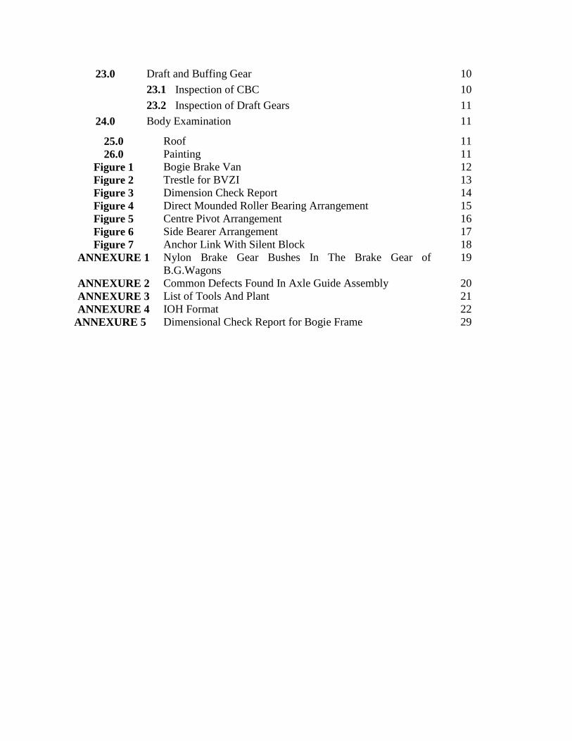
25.0 Roof 11
26.0 Painting 11
Figure 1 Bogie Brake Van 12
Figure 2 Trestle for BVZI 13
Figure 3 Dimension Check Report 14
Figure 4 Direct Mounded Roller Bearing Arrangement 15
Figure 5 Centre Pivot Arrangement 16
Figure 6 Side Bearer Arrangement 17
Figure 7 Anchor Link With Silent Block 18
ANNEXURE 1 Nylon Brake Gear Bushes In The Brake Gear of
B.G.Wagons
19
ANNEXURE 2 Common Defects Found In Axle Guide Assembly 20
ANNEXURE 3 List of Tools And Plant 21
ANNEXURE 4 IOH Format 22
ANNEXURE 5 Dimensional Check Report for Bogie Frame 29
23.0 Draft and Buffing Gear 10
23.1 Inspection of CBC 10
23.2 Inspection of Draft Gears 11
24.0 Body Examination 11
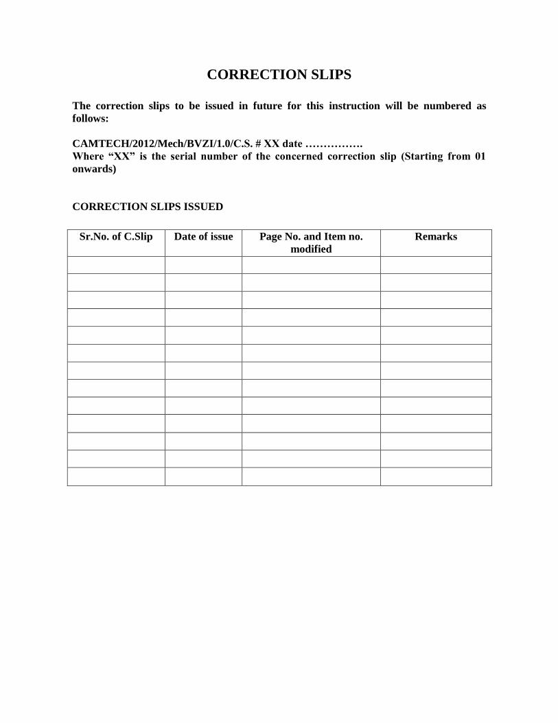
CORRECTION SLIPS
The correction slips to be issued in future for this instruction will be numbered as
follows:
CAMTECH/2012/Mech/BVZI/1.0/C.S. # XX date …………….
Where “XX” is the serial number of the concerned correction slip (Starting from 01
onwards)
CORRECTION SLIPS ISSUED
Sr.No. of C.Slip Date of issue Page No. and Item no.
modified
Remarks

Procedure for I.O.H of Broad Gauge BVZI
No.IRCAMTECH/2012/Mech/BVZI/1.0
Procedure for IOH of Broad Gauge (1676 mm) BVZI CAMTECH/GWL
1
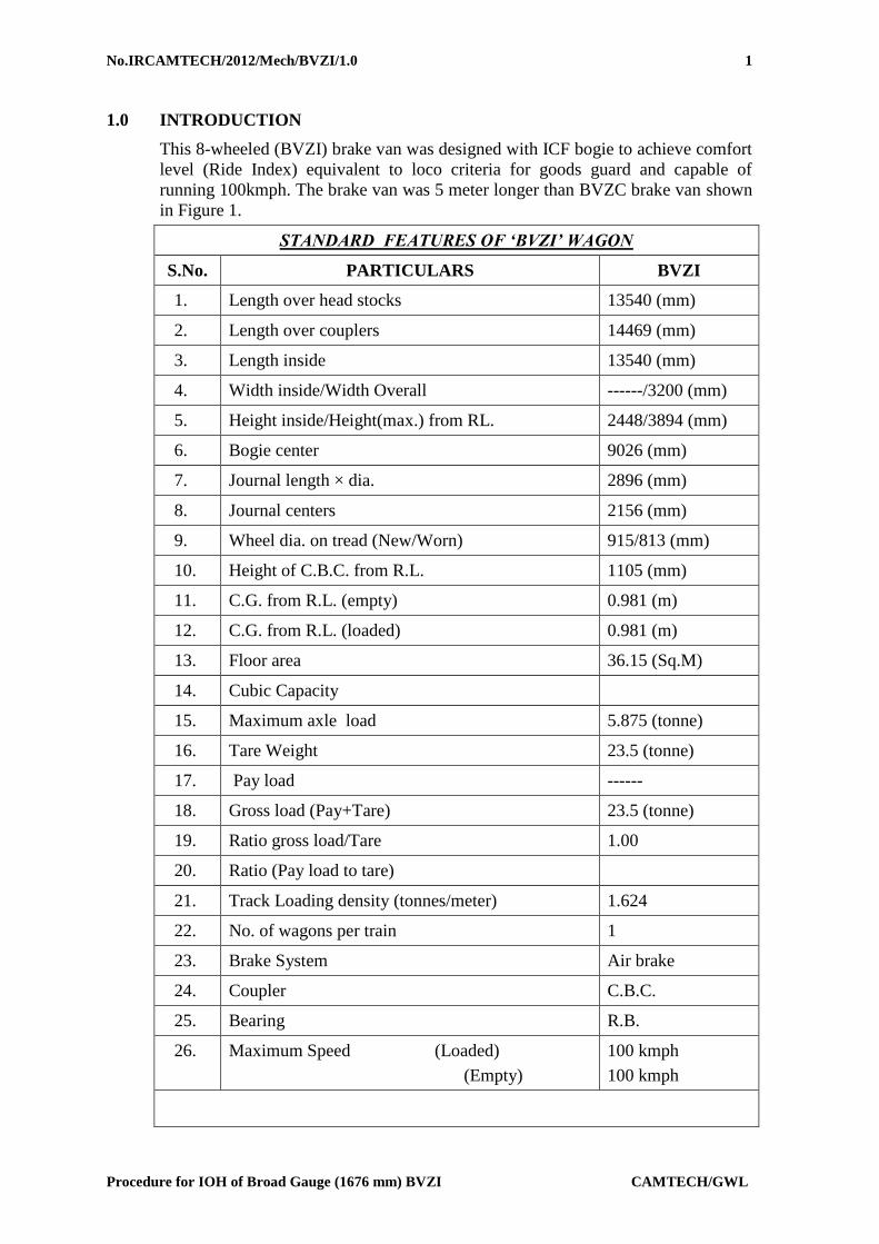
1.0 INTRODUCTION
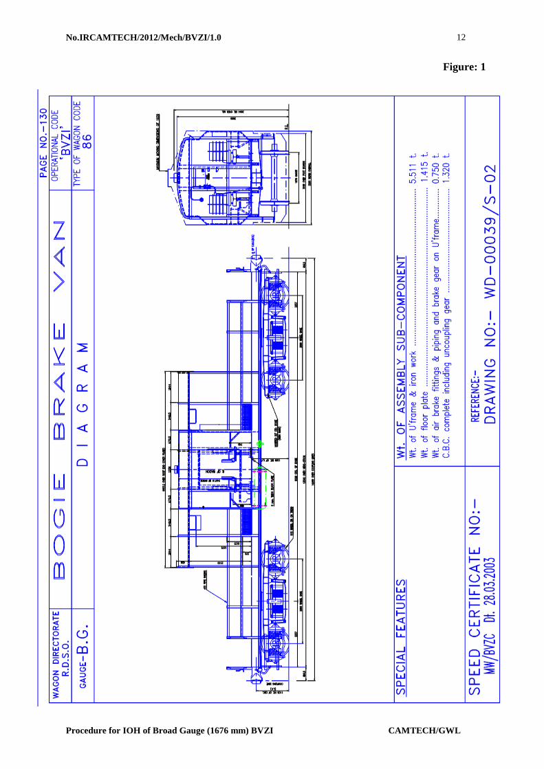
This 8-wheeled (BVZI) brake van was designed with ICF bogie to achieve comfort
level (Ride Index) equivalent to loco criteria for goods guard and capable of
running 100kmph. The brake van was 5 meter longer than BVZC brake van shown
in Figure 1.
STANDARD FEATURES OF ‘BVZI’ WAGON
S.No. PARTICULARS BVZI
1. Length over head stocks 13540 (mm)
2. Length over couplers 14469 (mm)
3. Length inside 13540 (mm)
4. Width inside/Width Overall ------/3200 (mm)
5. Height inside/Height(max.) from RL. 2448/3894 (mm)
6. Bogie center 9026 (mm)
7. Journal length × dia. 2896 (mm)
8. Journal centers 2156 (mm)
9. Wheel dia. on tread (New/Worn) 915/813 (mm)
10. Height of C.B.C. from R.L. 1105 (mm)
11. C.G. from R.L. (empty) 0.981 (m)
12. C.G. from R.L. (loaded) 0.981 (m)
13. Floor area 36.15 (Sq.M)
14. Cubic Capacity
15. Maximum axle load 5.875 (tonne)
16. Tare Weight 23.5 (tonne)
17. Pay load ------
18. Gross load (Pay+Tare) 23.5 (tonne)
19. Ratio gross load/Tare 1.00
20. Ratio (Pay load to tare)
21. Track Loading density (tonnes/meter) 1.624
22. No. of wagons per train 1
23. Brake System Air brake
24. Coupler C.B.C.
25. Bearing R.B.
26. Maximum Speed (Loaded)
(Empty)
100 kmph
100 kmph
No.IRCAMTECH/2012/Mech/BVZI/1.0
Procedure for IOH of Broad Gauge (1676 mm) BVZI CAMTECH/GWL
2
2.0 SAFETY PRECAUTIONS
Whenever a BVZI is examined at maintenance depot, it should be ensured
that the prescribed number of safety straps, safety wire rope, axle box safety
strap, bolster safety loop, centre pivot cap, hangers or brackets of specified
dimension and sections required for various components are fitted at
specified location.
All fasteners e.g. bolts, nuts, cotters etc. used in under frame equipments,
brake gear, buffing and draw gear should be checked.
3.0 DISMANTLING
Following procedure should be adopted for lifting and running out the bogies:
Remove split pin & cotter from top CP pin.
Remove Bogie pull rod pin.
Remove flexible brake pipe connections.
Unscrew Air vent Screw.
Uncouple dashpot safety strap.
4.0 PREPARATION BEFORE INSPECTION
BVZI body should be lifted off the bogies either by two overhead electric cranes of
15 tonnes capacity each with suitably designed lifting tackles or by four powered
lifting jacks of 10 tonnes capacity each operated simultaneously by one control
switch. The BVZI body should be lifted uniformly without jerks and should remain
horizontal during the lifting/ lowering operation.
The BVZI should never be lifted from one end only. If lifted from one end, the
Centre pivot is likely to suffer damages.
After the BVZI body is lifted, it should be kept on trestles. The revolving steel
trestles of the design shown in Figure 2. would prove useful for this purpose Lines
should be protected by scotch blocks with locking arrangement and key should be
kept with Engineer till the time maintenance work is carried out.
4.1 CLEANING
The entire under frame should be cleaned of dust, rust etc. from underneath by
pneumatic/water jet followed by wire brushing at critical locations and check for
cracks/damage, corrosion etc. on the under frame members
After carrying out all repairs, the under frame should be painted.
5.0 INSPECTION
5.1 BOGIE FRAME
Thoroughly cleaned and dried bogie frame should subjected to visual check for
possible cracks and weld cracks. Adoption of standard procedure for the inspection
and rectification of metal and weld failures is to be done for the first 10 bogie
frames.
5.2 BOGIE FRAME DIMENSIONS AND COMPONENTS
Bogie frame dimensions to be checked as per Figure 3.

No.IRCAMTECH/2012/Mech/BVZI/1.0
Procedure for IOH of Broad Gauge (1676 mm) BVZI CAMTECH/GWL
3
The following dimensional parameters should be checked and rectified as per
given format:
S.
No.
Description Parameters
1. Maximum Axle load bearing
capacity
6 t
2. Wheel base 2896mm
3. Wheel diameter (New) 915mm
4. Axle guidance Telescopic axle guide with oil
damping and Frication Snubber
type.
5. Primary suspension Coil spring
6. Secondary suspension Coil spring
7. Shock absorbers i) Vertical dashpot in primary
suspension.
ii) Hydraulic double acting
vertical shock absorber in
secondary suspension.
8. Transfer of coach body weight Through bogie side bearer
pitched at 1600mm.
6.0 AXLE BOX
On Indian Railway system, only single bearing type axle box arrangement is used.
The inner ring of the bearing is provided with either a cylindrical bore (Direct
Mounted type) or with a taper bore and withdrawal sleeve (Sleeve Mounted type).
use only direct mounted type spherical roller bearings.
7.0 BEARING
Roller bearing consist of an outer ring having a continuous spherical raceway
within which operate, two rows of barrel shaped rollers, which in turn are guided
by an inner ring with two raceways separated by a centre rib. The roller bearings
have self-aligning properties and therefore can automatically adjust to any
deviation in the centre line of the axle.
Roller bearings have a large capacity for radial loads, axle loads in either direction,
and complex loads. They are suited for the applications such as railway rolling
stocks where vibrations and shock loads are encountered.
Roller Bearings are named according to the shape of rollers. Roller Bearings with
spherical rollers are called as Spherical Roller Bearings.(see figure 4for roller
bearing arrangement)
These roller bearings need to be inspected periodically at a pre-defined schedule.
However, the following must be checked as per given format:

No.IRCAMTECH/2012/Mech/BVZI/1.0
Procedure for IOH of Broad Gauge (1676 mm) BVZI CAMTECH/GWL
4
S.N Description Specified Actual Rectification
1. Visual inspection
by rotating the
bearing to see
breakage in any part
of bearing
Free rotation
without noise
Replace
2. End play must be
checked
As per manual As per manual
8.0 BRAKES
The brake vans shall be equipped with single/Double pipe graduated release air
brake equipment. A typical arrangement and its details for fitment of these
equipments of M/s Escorts have been shown in Drg. No. WD – 810 35 / S- 21, 22
and 23. The arrangement shall be suitably altered for fitment of equipments of
other makes.
The brake arrangement shall be as shown in Drg. No. WD – 81035 / S – 10. Only
Nylon – 66 bushes in lieu of steel bushes wherever indicated in drawings to be
provided as per details given in Annexure 1
The following should also be inspected as per given format:
S.N Description Specified Actual Rectification
1. Visual inspection
for any crake or
loosening of the
components
No crakes or
loosening
Cracked part to
be replaced.
2. Hose crackes Even wear Alognment to
be right.
3. Function of Angle
cocks
As per manual Replace, if not
functioning
4 Functioning of
piston & stroke
As per manual Replace, if not
functioning
5. Joint and
connections
As per manual Replace, if not
functioning
9.0 WHEEL AND AXLE
The wheel should be inspected for rejectable defects in accordance with RDSO’s
instructions.
9.1 Pre-inspection of wheels
During pre-inspection of incoming wheels, the wheel-set is inspected for assessing
the condition of the components. Following measurements are carried out on all
the wheels, received in shop for repairs.
9.2 Measurement of a wheel gauge (distance between two wheels flanges on the
same axle)
No.IRCAMTECH/2012/Mech/BVZI/1.0
Procedure for IOH of Broad Gauge (1676 mm) BVZI CAMTECH/GWL
5
The distance between two wheel flanges on the same axle should be 1600 mm +
2/-1 mm. This measurement should be taken at three locations apart with the help
of an adjustable pi gauge.
9.3 Measurement of Wheel Diameter (Tread Diameter)/Wheel Flanges
The wheel diameter is measured with the help of a trammel gauge with a least
count of 0.5 mm. on both sides. However, a gauge with a least count of 0.1 mm.
is recommended as the measurement of a diameter would be more accurate with
this gauge.
The difference in tread diameter of the two wheels on the same axle should not
exceed 0.5 mm after tyre turning. There is no 'In service' limit for this variation
and rejection shall be decided by tyre defect gauge.
9.4 Inspection of Wheel Flanges
The flanges on both sides of a wheel set are checked with the help of a profile
gauge to measure the height and thickness of flanges. Accurate measurement of
flange height and flange thickness is not possible with the profile gauge. It is,
therefore, recommended to use a wheel profile gauge with which accurate
measurement of flange height and flange thickness to the extent of 0.1 mm can be
made.
10.0 AXLE BOX GUIDE WITH DASH POT ARRANGEMENT
Axle box guides are of cylindrical type welded to the bottom flanges of the bogie
side frame with close dimensional accuracy. These guides together with lower
spring seats located over the axle box wings, house the axle box springs and also
serve as shock absorbers. These guides are fitted with guide caps having nine holes
of diameter 5 mm equidistant through which oil in the lower spring seat passes
under pressure during dynamic oscillation of coach and provide necessary damping
to primary suspension to enhance better riding quality of Brake van. This type of
rigid axle box guide arrangement eliminates any longitudinal or transverse relative
movement between the axles and the bogie frame.
The quantity of oil required to achieve 40 mm oil level above the guide cap is
approximately 1.6 liters.
11.0 AIR VENT SCREWS
On the bogie side frames, directly above the dash-pots, tapped holes are provided
for replenishing oil in the dash pots. Special screws with copper asbestos washers
are screwed on the tapped hole to make it air tight
12.0 BOGIE BOLSTER SUSPENSION
The bolster rests on the bolster coil springs - two at each end, located on the lower
spring beam which is suspended from the bogie side frame by means of bolster-
spring-suspension (BSS) hangers on either side. The two anchor links diagonally
positioned are provided with silent block bushes. The links prevent any relative
movement between the bogie frame and coach body.
13.0 SPRINGS
In ICF bogie, helical springs are used in both primary and secondary suspension.
The springs are manufactured from peeled and centreless ground bar of chrome
vanadium/chrome molybdenum steel conforming to Drawing no. WD-04050-S-02
No.IRCAMTECH/2012/Mech/BVZI/1.0
Procedure for IOH of Broad Gauge (1676 mm) BVZI CAMTECH/GWL
6
14.0 CENTRE PIVOT ARRANGEMENT
The centre pivot pin joins the body with the bogie and transmits the tractive and
braking forces on the bogies. It does not transmit any vertical load. It is equipped
with rubber silent block bushes which tend to centralise the bogies with respect to
the body and, to some extent, control and damp the angular oscillations of the
bogies. ( see figure 5.)
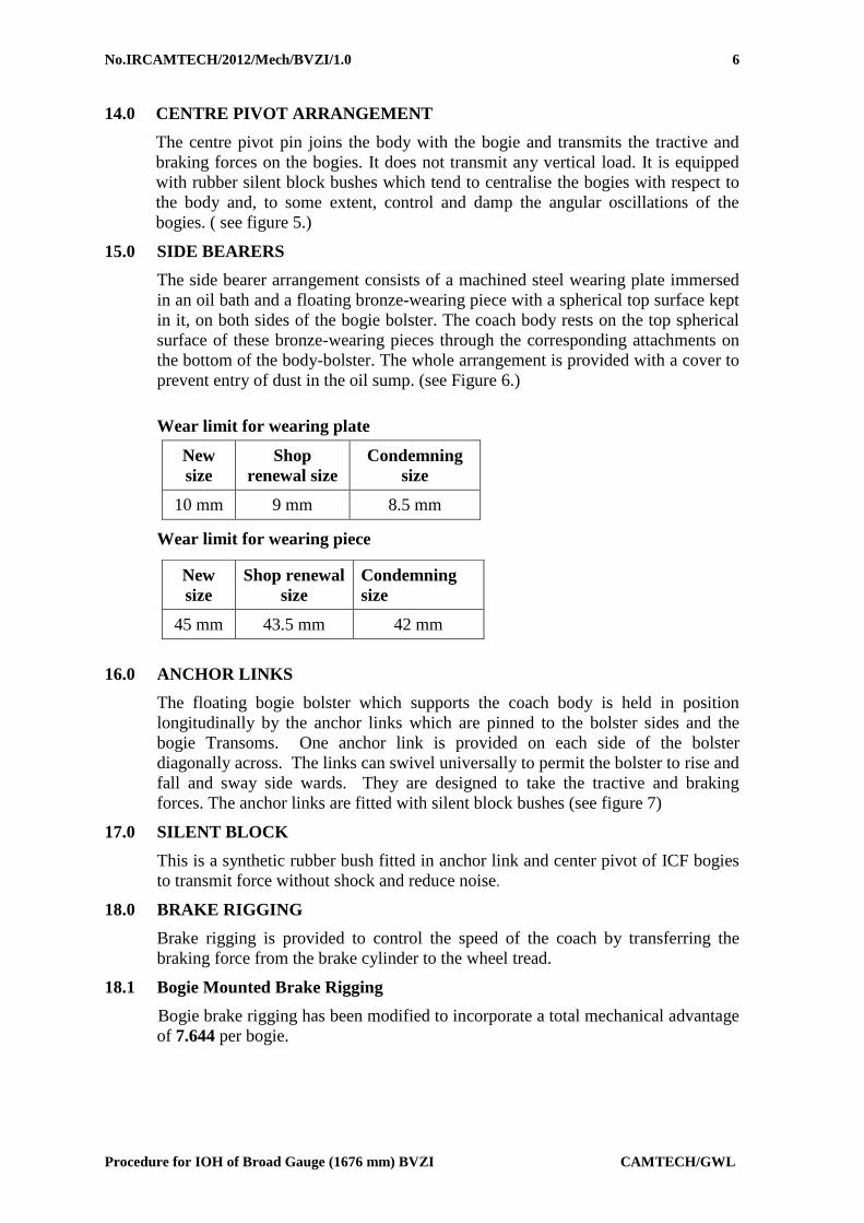
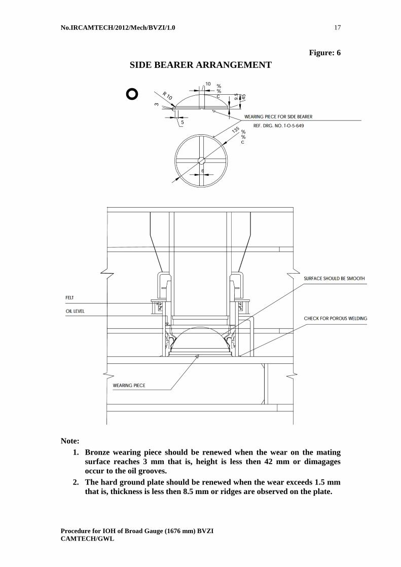
15.0 SIDE BEARERS
The side bearer arrangement consists of a machined steel wearing plate immersed
in an oil bath and a floating bronze-wearing piece with a spherical top surface kept
in it, on both sides of the bogie bolster. The coach body rests on the top spherical
surface of these bronze-wearing pieces through the corresponding attachments on
the bottom of the body-bolster. The whole arrangement is provided with a cover to
prevent entry of dust in the oil sump. (see Figure 6.)
Wear limit for wearing plate
New
size
Shop
renewal size
Condemning
size
10 mm 9 mm 8.5 mm
Wear limit for wearing piece
16.0 ANCHOR LINKS
The floating bogie bolster which supports the coach body is held in position
longitudinally by the anchor links which are pinned to the bolster sides and the
bogie Transoms. One anchor link is provided on each side of the bolster
diagonally across. The links can swivel universally to permit the bolster to rise and
fall and sway side wards. They are designed to take the tractive and braking
forces. The anchor links are fitted with silent block bushes (see figure 7)
17.0 SILENT BLOCK
This is a synthetic rubber bush fitted in anchor link and center pivot of ICF bogies
to transmit force without shock and reduce noise.
18.0 BRAKE RIGGING
Brake rigging is provided to control the speed of the coach by transferring the
braking force from the brake cylinder to the wheel tread.
18.1 Bogie Mounted Brake Rigging
Bogie brake rigging has been modified to incorporate a total mechanical advantage
of 7.644 per bogie.
New
size
Shop renewal
size
Condemning
size
45 mm 43.5 mm 42 mm

No.IRCAMTECH/2012/Mech/BVZI/1.0
Procedure for IOH of Broad Gauge (1676 mm) BVZI CAMTECH/GWL
7
The components of bogie mounted air brake.
S.N Description Ref. Drg. NO
ICF)
Quantity
1 Brake Head & block complete (L.H.
Assembly)
T-3-1-801 4
2 Brake Head & block complete (R.H.
Assembly )
T-3-1-801 4
3 Brake beam T-3-1-804 4
4 lever T-3-1-802 4
5 lever T-3-1-802 4
6 lever Hanger T-3-1-802 4
7 Pull rod T-3-2-802 2
8 Brake block Hanger T-3-1-645 8
9 Pin T3-2-648 22
10 Plain Washer ICF/STD-3-2-103 32
11 Split Cotter T-3-2-632 26
12 Pin T-3-2-648 2
13 Plain Washer ICF/STD 3-2-103 2
14 Pin T-3-2-648 2
15 Pin for lever Hanger T-3-2-802 8
16 Pin for safety wire rope WFT AC3/3-2-
307
16
17 Plain washer M20 IS: 2016-67 16
18 Split cotter EMU-3-2-048 16
19 Safety wire rope T-3-2-651 8
19.0 EQUALISING STAYS
This device has been provided on bogies between the lower spring plank and the
bolster to prevent lateral thrust on the bolster springs which have not been designed
to take the lateral forces. These links have pin connections at both ends and,
therefore, can swivel freely.
20.0 BOLSTER SPRING SUSPENSION HANGERS (BSS HANGERS)
In the secondary suspension, the bolster is supported on helical coil springs which
are placed on the lower spring plank. The lower spring plank is suspended from
the bogie side frame through BSS hangers on hanger blocks.
21.0 SHOCK ABSORBERS
Hydraulic shock absorbers with capacity of 600 kg at a speed of 10 cm/sec. are
fitted to work in parallel with the bolster springs to provide damping for vertical
oscillations.

No.IRCAMTECH/2012/Mech/BVZI/1.0
Procedure for IOH of Broad Gauge (1676 mm) BVZI CAMTECH/GWL
8
22.0 THOUGHLY EXAMINATION AND REPAIR PRACTICE IN IOH DEPOT
Depot maintenance staff should ensure the following things in respect of
proper functioning and safety of Bogie & Bogie components.
22.1 Bogie Frame
Examine visually condition of bogie side frame, transom, longitudinals and all
welded locations.
Examine rubber stopper/stop screw of axle box crown for
damage/missing/loose.
Inspect axle box safety straps/loops for damage/broken/missing.
Bolster safety straps/loops for damage/broken/missing.
Brake hanger brackets for damages.
Inspect safety brackets for brake hanger pins.
Check visually BSS hanger brackets.
Examine visually anchor link brackets.
Visually examine centre pivot mounting bolts and attend if needed.
Visually inspect centre pivot cover.
Side bearer oil to be replenished, if needed.
Examine condition of wearing piece and wearing plate
Examine oil level in side bearer oil baths and replenish if oil level has gone
down below the level of last thread of oil filling cup.
22.2 Primary Suspension
Visually examine axle box springs for breakage.
Visually examine dash pot oil filling special screw for deficiency.
Check oil leakage in dash pot through defective seals/vent screws.
Visually examine axle box clearance
Add specified grade of oil in dash pot.
Visually examine axle box clearance.
Check and attend axle guide assembly if necessary.
Check axle box clearance with gauge
22.3 Secondary Suspension
Visually examine bolster springs breakages/damages.
Visually examine Bolster lower spring beam.
Visually examine BSS hangers, hanger blocks, BSS pins.
Check bolster clearance between top of bolster and bottom of bogie frame.
Visually examine equalising stay rods and pins (small and big).
Visually check anchor links
Examine Visually anchor link securing bolts and attend if needed.
Visually examine Equalising stay rod brackets.
Examine and attend safety loops of bolster.
Check and attend safety loops of Equalising stay rod.
Examine vertical shock absorbers for damages

No.IRCAMTECH/2012/Mech/BVZI/1.0
Procedure for IOH of Broad Gauge (1676 mm) BVZI CAMTECH/GWL
9
22.4 Brake Rigging
Check brake gear and adjust so that the piston stroke is within the limit.
Examine brake beams breakages/damages.
Check and attend brake beam safety wire ropes/safety straps.
Check and attend brake shoe head and key & replace if necessary.
Check and replace worn brake blocks.
Visually inspect and replace brake hangers, brake gear pins and cotters/split
pins if necessary.
Visually inspect and replace damaged/missing brake gear bushes if necessary
Check and attend brake block adjuster.
Examine and attend brake levers.
Examine and attend floating lever suspension brackets
Examine lever hanger pins.
No.IRCAMTECH/2012/Mech/BVZI/1.0
Procedure for IOH of Broad Gauge (1676 mm) BVZI CAMTECH/GWL
10
23.0 DRAFT AND BUFFING GEAR
The brake van shall be equipped with automatic high tensile center buffer coupler
of knuckle type.
23.1 INSPECTION OF CBC
Coupler and operating mechanism:
When inspection of coupler and coupler operating mechanism is made, it is
important to check and make sure that when the coupler operating mechanism is
operated to fully open the knuckle, the handle released and the knuckle slowly
closed, the lock drops freely and the mechanism returns to fully locked position.
The lock position is indicated by the toggle, which is clearly visible below the
coupler head.
Only dry lubricant shall be applied to the coupler head or the coupler head fittings.
This lubricant may be applied using water, alcohol, or other non-petroleum based
carrier.
Only exposed surfaces of Coupler and Yoke shall be painted with Black quick
drying paint in accordance with IRS R6. Paint must be applied to the inside of
the Coupler or internal fittings. Painting shall be done after the completion of
inspection of Coupler & Yoke of acceptable casting lot.
When in the transition Centre Buffer Coupler, the knuckle does not move
freely, grind the top face of "top pulling lug" and "lock face" of knuckle
in position. If still not free, remove knuckle and clean "pin protector guides” on
coupler head. If, after attending to knuckle, the lock still does not fall, remove
the lock and grind “locking face knuckle side” on lock so that the lock falls
freely.
Inspection of couplers, whilst fitted to wagons, should be made to ensure that
proper clearance is available to prevent interference in any position which it
can assume during train operation. The procedure is as follows:-
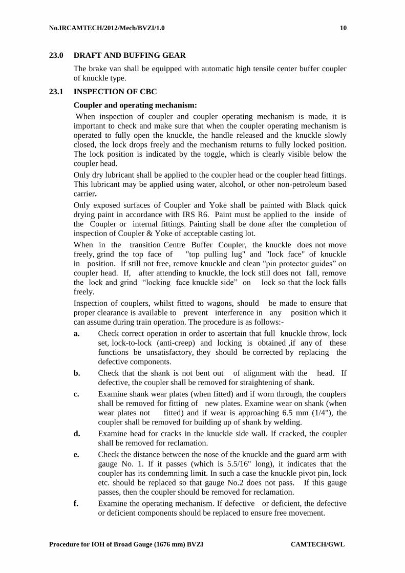
a. Check correct operation in order to ascertain that full knuckle throw, lock
set, lock-to-lock (anti-creep) and locking is obtained ,if any of these
functions be unsatisfactory, they should be corrected by replacing the
defective components.
b. Check that the shank is not bent out of alignment with the head. If
defective, the coupler shall be removed for straightening of shank.
c. Examine shank wear plates (when fitted) and if worn through, the couplers
shall be removed for fitting of new plates. Examine wear on shank (when
wear plates not fitted) and if wear is approaching 6.5 mm (1/4"), the
coupler shall be removed for building up of shank by welding.
d. Examine head for cracks in the knuckle side wall. If cracked, the coupler
shall be removed for reclamation.
e. Check the distance between the nose of the knuckle and the guard arm with
gauge No. 1. If it passes (which is 5.5/16" long), it indicates that the
coupler has its condemning limit. In such a case the knuckle pivot pin, lock
etc. should be replaced so that gauge No.2 does not pass. If this gauge
passes, then the coupler should be removed for reclamation.
f. Examine the operating mechanism. If defective or deficient, the defective
or deficient components should be replaced to ensure free movement.
No.IRCAMTECH/2012/Mech/BVZI/1.0
Procedure for IOH of Broad Gauge (1676 mm) BVZI CAMTECH/GWL
11
g. Check knuckle pin & clevis pin to ensure that pin of correct size has been
used. Check fastening arrangement of knuckle pin and clevis pin. The
former has a welded washer while the later has a riveted head over a
washer in position.
h. Coupler height should be checked in accordance with IRCA Part III Rule
No. 2.13.7.
i. All defective/deficient components shall be replaced in CBC, clevis and
screw coupling (in case of transition couplers).
23.2 Inspection of draft gears
A. Excessive slack in draft gears is not permitted and this should be
either reduced or eliminated. The maximum permissible free slack in the
draft gear is 25 mm(1") after which, it shall be removed and reclaimed or
condemned. The free slack can be determined by first sledging the coupler
back solid and then measuring the clearance between the coupler horn and
the striker face. Next by inserting a long bar between the horn and striker
face, pry coupler out as far as possible and again measure the space
between the horn and the striker. The difference between these two
measurements is the amount of free slack.
B. Visual examination of the rubber pads when the draft gear is in place in the
wagon can be misleading and the draft gears shall therefore, be inspected
at every POH of the wagon, irrespective of the amount of free slack
existing.
24.0 BODY EXAMINATION
Properly check Guard’s Hand brake components and oiling of gears.
Inspect door fittings
Inspect and check quick coupling for function properly.
Inspect and check Guard’s sheet and table.
Inspect and check side look out glass, window glass and window shatter.
Inspect and check hand rail and foot step.
25.0 ROOF
The roof shall be checked for mild rusting and leakage of water. rust shall be
removed by use of suitable emery and a matching coat of paint applied. any
accumulated waste matter should be removed from the corrugations.
26.0 PAINTING
The surface preparation and Schedule of Painting of Brake Vans shall be as
indicated in Clause 11 of General Standard – Specification no. G-72 (Rev. 2).
************
No.IRCAMTECH/2012/Mech/BVZI/1.0
Procedure for IOH of Broad Gauge (1676 mm) BVZI CAMTECH/GWL
12
Figure: 1

No.IRCAMTECH/2012/Mech/BVZI/1.0
Procedure for IOH of Broad Gauge (1676 mm) BVZI CAMTECH/GWL
13
Figure: 2
TRESTEL FOR BVZI

No.IRCAMTECH/2012/Mech/BVZI/1.0
Procedure for IOH of Broad Gauge (1676 mm) BVZI CAMTECH/GWL
14
Figure: 3
DIMENSION CHECK REPORT
BOGIE SIDE FRAME & HEAD STOCK CENTRES ON EITHER SIDE OF THE BOGIE BE WELDED
AT THE LONGITUDINAL AND TRANSVERSE CENTRES OF THE BOGIE CONSPICUOUS
MANNER.TO ENSURE THIS 2MMTHICK X 25MMWIDE STRIP SHOULD FRAME AS SHOWN
THUS WILL BE PERMANENTLY PUNCH MARKED IN FRAME.PUNCH MARK SHOULD BE
PUNCHED ON THIS STRIP ACCORDINGLY.
G 1 TO G 8 REPRESENT LOCATIONS OF BOGIE GUIDES.
E,F,G & H REPRESENT LOCATIONS OF SUSPENSION BRACKETS FOR BOLSTER SUSPENSION
ARRGT.
BOLSTER SUSPENSION BRACKET PIN HOLES E,F,G,H SHALL BE LOCATED AT 700 0.5MM
FROM THE TRANSVERSE CENTRE LINE PUNCH MARKS ON BOGIE SIDE FRAME & CHECK IT
AS PER FIG.
WELDING JOINT SHALL NOT COME UNDER THE BOGIE GUIDE.
NO INACCURACY IN LOCATION OF HANGER BRACKET AND THE ALIGNMENT OF HOLES IN
THE BRACKETS WILL BE PERMITTED.

No.IRCAMTECH/2012/Mech/BVZI/1.0
Procedure for IOH of Broad Gauge (1676 mm) BVZI
CAMTECH/GWL
15
Figure: 4
DIRECT MOUNED ROLLER BEARING ARRANGEMENT

No.IRCAMTECH/2012/Mech/BVZI/1.0
Procedure for IOH of Broad Gauge (1676 mm) BVZI
CAMTECH/GWL
16
Figure: 5
CENTRE PIVOT ARRANGEMENT
No.IRCAMTECH/2012/Mech/BVZI/1.0
Procedure for IOH of Broad Gauge (1676 mm) BVZI
CAMTECH/GWL
17
Figure: 6
SIDE BEARER ARRANGEMENT
Note:
1. Bronze wearing piece should be renewed when the wear on the mating
surface reaches 3 mm that is, height is less then 42 mm or dimagages
occur to the oil grooves.
2. The hard ground plate should be renewed when the wear exceeds 1.5 mm
that is, thickness is less then 8.5 mm or ridges are observed on the plate.

No.IRCAMTECH/2012/Mech/BVZI/1.0
Procedure for IOH of Broad Gauge (1676 mm) BVZI
CAMTECH/GWL
18
Figure: 7
ANCHOR LINK WITH SILENT BLOCK

No.IRCAMTECH/2012/Mech/BVZI/1.0
Procedure for IOH of Broad Gauge (1676 mm) BVZI CAMTECH/GWL
19
ANNEXURE -1
NYLON BRAKE GEAR BUSHES IN THE BRAKE GEAR OF B.G.WAGONS
1. Brake gear bushes of Nylon-66 shall be procured as per Schedule of Technical
Requirements (STR) No. WD-04-Nylon Bushes-2002.
2. Nominal dimensions of Nylon-66 bushes to be used will be same as of steel bushes,
inclusive of step sizes out side diameter. However, the tolerance and the chamfering
should be as per Fig.1 of the ‘STR’.
3. Undersized holes should be drilled initially in the fork type support brackets or fork
end of pull/push rods. These holes should be drilled together to the required size
only after the assembly but before the Nylon bushes are fitted therein. This will
ensure that the two holes are concentric and therefore, the pins passing through the
bushes fitted therein will not tilt.
4. Steel pins used with the Nylon-66 bushes shall be with fine finish machined on all
contact surface with the bush.

No.IRCAMTECH/2012/Mech/BVZI/1.0
Procedure for IOH of Broad Gauge (1676 mm) BVZI CAMTECH/GWL
20
ANNEXURE -2
COMMON DEFECTS FOUND IN AXLE GUIDE ASSEMBLY
S.No. Defects Reason Remedies
1. Perished rubber
packing ring
Poor quality of
rubber packing ring
1) Replace rubber packing ring at
every examination.
2) Use only rubber packing rings
conforming to IRS specification
no. R-47-72 and the relevant
drawing.
2. Axle guide found
worn on one side
1) Misaligned
fitment of axle
guides to bogie
frame.
2) Dust ingress to
lower spring
seat.
1) The alignment of axle box guide
should be checked with
alignment gauges and corrected.
2) Vent hole should be sealed with
gaskets. Screw to be tightened
well after oil topping.
3. Axle box spring
rubbing upper
spring seat
Do Do
4. Guide bush worn Do Do
5 Lower spring
surface worn
Do Do
6. Guide ring broken 1) Axle guide is
hitting lower
spring seat
2) Weld joint of
lower spring
seat and tube is
porous or
cracked
1) Guide securing bolt should not
project out of guide cap.
2) Use good quality upper and
lower rubber washers and
correct number of compensating
rings in the axle guide assembly.
3) Adjust A, B and C clearances on
leveled track.
4) Strip and reweld lower spring
seat correctly.
7 Guide cap securing
assembly broken
Do Do
8. Lower spring seat
scored and dent
mark on guide cap
Do Do
9 Dust shield spring
broken or distorted
Do Do
10 Leakage from lower
spring seat
Do Do

No.IRCAMTECH/2012/Mech/BVZI/1.0
Procedure for IOH of Broad Gauge (1676 mm) BVZI CAMTECH/GWL
21
ANNEXURE -3
LIST OF TOOLS AND PLANT
LIFTING SHOP
Ball peen hammer
Chisel
Spanner
WASHING PLANT
Bosch tank
Hot water jet system
Bins and pallets
Jib crane
Fork lift
Platform truck
BOGIE SHOP
Ball peen hammer
Chisel
Spanner set
Welding transformer
Gas cutting plant
Bogie alignment gauges
Spring testing machine
Magnaflux crack detector
Paint brushes
Floor scraper
Bogie frame repair fixture
Bolster repair fixture
Bogie test rig
Working stands
Overhead crane
Bins and pallets
Fork lift
Platform truck
FITTING SHOP
Ball peen hammer
Chisel
Welding transformer
Gas cutting plant
Hydraulic press
Measuring gauges
Center lathe
Brake beam end turning m/c
Electrode heater
Hard surface plant
BSS hanger testing m/c
Bins and pallets
Fork lift
Platform truck
SMITH SHOP
Helical spring repair tools & plant
Shot peening plant
Heat treatment plant
Smith’s tongs, hammers & blocks

No.IRCAMTECH/2012/Mech/BVZI/1.0
Procedure for IOH of Broad Gauge (1676 mm) BVZI CAMTECH/GWL
22
ANNEXURE -4
IOH FORMAT
BVZI NUMBER BASE STATION
TYPE SERVICE
YEAR BUILT MANUFACTURED BY
LAST POH
RETURN DATE
BOGIE DETAILS
ICV end NICV end
Bogie No:
Year Built:
Manufactured By:
DATE OF IOH
DATE OF RELEASE
SSE/IOH SE/JE/IO

No.IRCAMTECH/2012/Mech/BVZI/1.0
Procedure for IOH of Broad Gauge (1676 mm) BVZI CAMTECH/GWL
23
BOGIE DETAILS
DESCRIPTION ICV END NICV END REMARKS
Bogie frame condition Cracked/ Worn out/ good Cracked/ worn out / good
Bolster Cracked/ bent/ good/ renewed Cracked/ bent/ good/ renewed
Bolster suspension bracket Cracked/corroded/good/renewed Cracked/ corroded/good/renewed
Lower spring seat Cracked/ worn out/good/renewed Cracked/ worn out/good/renewed
Axle guide Worn/misalign/good Worn/misalign/good
Axle guide cap/
modified/unmodified
Dropped /good/replaced/modified Dropped/good/replaced/modified
Axle guide assembly Worn out/damaged/good/renewed Worn out/damaged/good/renewed
Guide bush Worn out/good/renewed Worn out/ good/renewed
Packing rings rubber Damaged/good/renewed Damaged/good/renewed
Protective tubes Cracked/good/renewed Cracked/good/renewed
Equalizing stay Bent/corooded/good/renewed/13/16
tonnes
Bent/corooded/good/renewed/13/16
tonnes
Anchor links Damaged/good/renewed Damaged/good/renewed
Bolster suspension hanger block Gauged/good/renewed Gauged/good/renewed
Bolster suspension hanger pin Gauged/good/renewed Gauged/good/renewed
Center pivot Bolt loose/worn/good/renewed Bolt loose/worn/good/renewed
Center pivot silent block Silent block
damaged/renewed/good
Silent block damaged/renewed/good
Side bearer Damaged/good Damaged/good
No.IRCAMTECH/2012/Mech/BVZI/1.0
Procedure for IOH of Broad Gauge (1676 mm) BVZI CAMTECH/GWL
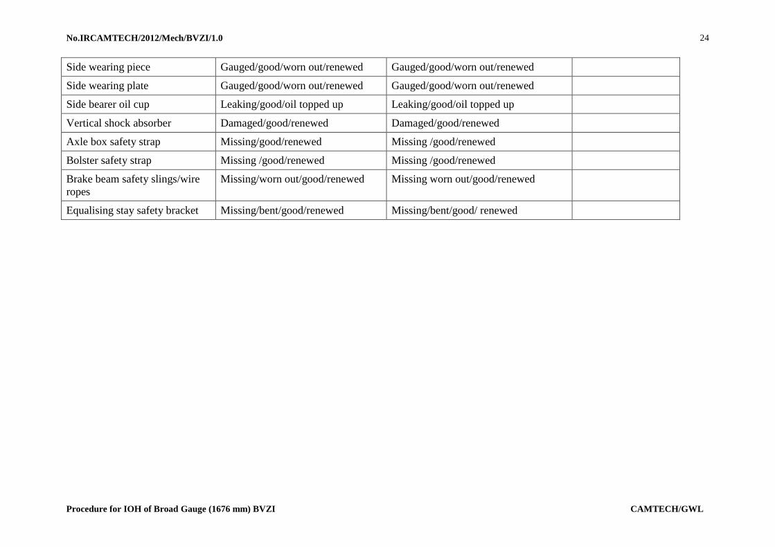
24
Side wearing piece Gauged/good/worn out/renewed Gauged/good/worn out/renewed
Side wearing plate Gauged/good/worn out/renewed Gauged/good/worn out/renewed
Side bearer oil cup Leaking/good/oil topped up Leaking/good/oil topped up
Vertical shock absorber Damaged/good/renewed Damaged/good/renewed
Axle box safety strap Missing/good/renewed Missing /good/renewed
Bolster safety strap Missing /good/renewed Missing /good/renewed
Brake beam safety slings/wire
ropes
Missing/worn out/good/renewed Missing worn out/good/renewed
Equalising stay safety bracket Missing/bent/good/renewed Missing/bent/good/ renewed
No.IRCAMTECH/2012/Mech/BVZI/1.0
Procedure for IOH of Broad Gauge (1676 mm) BVZI CAMTECH/GWL
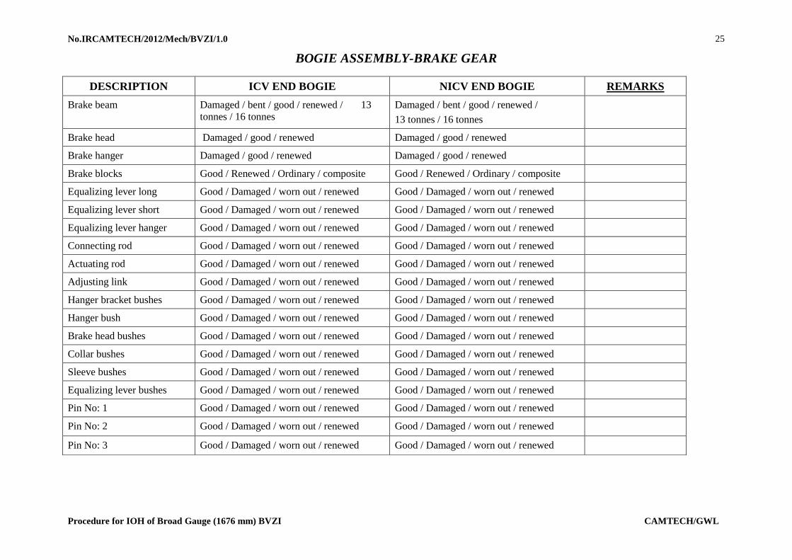
25
BOGIE ASSEMBLY-BRAKE GEAR
DESCRIPTION ICV END BOGIE NICV END BOGIE REMARKS
Brake beam Damaged / bent / good / renewed / 13
tonnes / 16 tonnes
Damaged / bent / good / renewed /
13 tonnes / 16 tonnes
Brake head Damaged / good / renewed Damaged / good / renewed
Brake hanger Damaged / good / renewed Damaged / good / renewed
Brake blocks Good / Renewed / Ordinary / composite Good / Renewed / Ordinary / composite
Equalizing lever long Good / Damaged / worn out / renewed Good / Damaged / worn out / renewed
Equalizing lever short Good / Damaged / worn out / renewed Good / Damaged / worn out / renewed
Equalizing lever hanger Good / Damaged / worn out / renewed Good / Damaged / worn out / renewed
Connecting rod Good / Damaged / worn out / renewed Good / Damaged / worn out / renewed
Actuating rod Good / Damaged / worn out / renewed Good / Damaged / worn out / renewed
Adjusting link Good / Damaged / worn out / renewed Good / Damaged / worn out / renewed
Hanger bracket bushes Good / Damaged / worn out / renewed Good / Damaged / worn out / renewed
Hanger bush Good / Damaged / worn out / renewed Good / Damaged / worn out / renewed
Brake head bushes Good / Damaged / worn out / renewed Good / Damaged / worn out / renewed
Collar bushes Good / Damaged / worn out / renewed Good / Damaged / worn out / renewed
Sleeve bushes Good / Damaged / worn out / renewed Good / Damaged / worn out / renewed
Equalizing lever bushes Good / Damaged / worn out / renewed Good / Damaged / worn out / renewed
Pin No: 1 Good / Damaged / worn out / renewed Good / Damaged / worn out / renewed
Pin No: 2 Good / Damaged / worn out / renewed Good / Damaged / worn out / renewed
Pin No: 3 Good / Damaged / worn out / renewed Good / Damaged / worn out / renewed

No.IRCAMTECH/2012/Mech/BVZI/1.0
Procedure for IOH of Broad Gauge (1676 mm) BVZI CAMTECH/GWL
26
UNDER FRAME
Head stock Corroded / cracked / good Corroded / cracked / good
Trough floor Corroded / good Corroded / good
Sole bar Corroded / good Corroded / good
Cross members Corroded / good Corroded / good
Diagonals Corroded / good Corroded / good
Main transom Corroded / good Corroded / good
Inner headstock Corroded / good Corroded / good
Train pipe and joints Corroded / good Corroded / good
Dummy carrier & dummy plug Missing / good / Renewed Missing / good / renewed
CONDITION OF WHEEL & AXLE – ON ARRIVAL
Location Diameter Wheel distance Axle number Tyre profile Condition of flange & thickness
L-1/R-1
L-2/R-2
L-3/R-3
L-4/R-4

No.IRCAMTECH/2012/Mech/BVZI/1.0
Procedure for IOH of Broad Gauge (1676 mm) BVZI CAMTECH/GWL
27
CONDITION OF WHEEL & AXLE ON DESPATCH
Location Tyre turned /
not turned
Wheel dia Wheel
distance
Axle
number
UST number Axle pulley
condition
If shop wheel, SL
number
L-1/R-1
L-2/R-2
L-3/R-3
L-4/R-4
CONDITION OF AXLE SPRINGS – ARRIVAL
Axle springs 1 2 3 4 5 6 7 8
Left Broken /
good
Broken /
good
Broken /
good
Broken /
good
Broken /
good
Broken /
good
Broken /
good
Broken /
good
Right Broken /
good
Broken /
good
Broken /
good
Broken /
good
Broken /
good
Broken /
good
Broken /
good
Broken /
good
CONDITION OF AXLE SPRINGS – AFTER IOH
Axle spring
height
1 2 3 4 5 6 7 8
Left
Right
No.IRCAMTECH/2012/Mech/BVZI/1.0
Procedure for IOH of Broad Gauge (1676 mm) BVZI CAMTECH/GWL
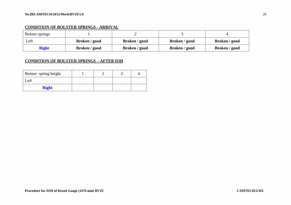
28
CONDITION OF BOLSTER SPRINGS - ARRIVAL
Bolster springs 1 2 3 4
Left Broken / good Broken / good Broken / good Broken / good
Right Broken / good Broken / good Broken / good Broken / good
CONDITION OF BOLSTER SPRINGS – AFTER IOH
Bolster spring height 1 2 3 4
Left
Right

No.IRCAMTECH/2012/Mech/BVZI/1.0
Procedure for IOH of Broad Gauge (1676 mm) BVZI CAMTECH/GWL
29
Annexure-5
DIMENSIONAL CHECK REPORT FOR BOGIE FRAME
No. ………………….
Measuring
Point
Nominal Size
(mm)
Actual Size
(mm)
Variation
(mm)
Measuring
Point
Nominal Size
(mm)
Actual Size
(mm)
Variation
(mm)
E - F 1500 1.0 I - J 876 0.5
G - H 1500 1.0 J - K 876 0.5
E - G 2159 1.0 L - M 876 0.5
F - H 2159 1.0 M - N 876 0.5
E - H 2629 1.0 O - P 876 0.5
F - G 2629 1.0 P- Q 876 0.5
a 413 1.0 R - S 876 0.5
b 413 1.0 S - T 876 0.5
c 413 1.0 I - K 1752 1.0
d 413 1.0 L - N 1752 1.0
g1 - g2 570 1.0 O - Q 1752 1.0
g3 - g4 570 1.0 R - T 1752 1.0
g5 - g6 570 1.0 g1 - g6 3612 1.0
g7 - g8 570 1.0 g2 - g5 3612 1.0
z - F 750 0.5 g3 - g8 3612 1.0
z - H 750 0.5 g4 - g7 3612 1.0
ICF
DR
G. N
O. W
TA
C3 0
-3-3
01
Procedure for I.O.H of Broad Gauge BVZI
OUR OBJECTIVE
To upgrade maintenance technologies and methodologies and achieve improvement in productivity and performance of all Railway assets and man power which inter-alia would cover
reliability, availability, utilization and efficiency.
If you have any suggestions and any specific comments, please write to us. Contact person : Director (Mech.) Postal address : Indian Railways,
Centre for Advanced Maintenance Technology,
Maharajpur, Gwalior. Pin code - 474 005 Phone : 0751- 470890, 0751-470803 Fax : 0751- 470841


