

7/31/2019 Prod White Paper0900aecd802c8630
http://slidepdf.com/reader/full/prod-white-paper0900aecd802c8630 1/10
Cisco Systems, Inc.All contents are Copyright © 1992–2005 Cisco Systems, Inc. All rights reserved. Important Notices and Privacy Statement.
Page 1 of 9
WHITE PAPER
EFFICIENT AND FLEXIBLE TRANSPORT OF NEXT-GENERATION DATASERVICES OVER SONET/SDH USING GFP, VCAT AND LCAS
Service providers today face an increasing number of challenges in addressing customer demand for new services while
continuing to deliver traditional voice and private line services. Until recently, new services such as Ethernet and storage
area networks (SANs) could not efficiently be delivered over existing SONET/SDH networks despite the proven value of,
and considerable investment in this infrastructure. However, the maturity of three new technologies—Generic Framing
Procedure (GFP), Virtual Concatenation (VCAT), and Link Capacity Adjustment Scheme (LCAS)—can transform this
infrastructure to make it both an efficient and flexible transport network to meet the demand for Layer 2 and Layer 3
services. This white paper offers an overview of the benefits these three stable and mature technologies bring to
SONET/SDH networks, thereby allowing service providers to extract greater value from their networks.
EVOLVING THE SONET/SDH INFRASTRUCTURE FOR DELIVERY OF DATA SERVICES
INTRODUCTION
Over the years, service providers have invested considerable amounts of capital and expertise in their SONET/SDH networks. These
networks have proven their value because they offer bandwidth and infrastructure scalability; operation, administration, maintenance, and
provisioning (OAM&P) capability; and reliable network protection and restoration. However, SONET/SDH technologies were developed
almost three decades ago to transport 64-kbps (DS0) voice circuits, not for data services. Today, service providers are under intense pressure
because of the market’s rapid migration from voice and traditional private line to new IP-based services, such as voice over IP (VoIP) VPNs,
videoconferencing, IP television, and online gaming, just to name a few. These changes are occurring in parallel with customers’ increased
need for all types of Layer 2 network connectivity, particularly Ethernet, Enterprise Systems Connection (ESCON) Fiber Connection
(FICON) for mainframe applications, and Fibre Channel, an open protocol for SANs.
Three mature technologies—GFP, VCAT, and LCAS—together solve the following issues that exist in an infrastructure optimized for DS0
services:
• Difficulty of mapping newer (Ethernet, SANs) services to the existing transport network
• Inefficient use of the transport network in delivering data services
• Inability to increase or decrease available bandwidth to meet the needs of data services without impacting traffic
This demand for multiple services is being addressed by multiservice provisioning platforms (MSPPs), such as the market-leading Cisco®
ONS
15300 Series and the Cisco ONS 15454 MSPP. These platforms today offer service providers a way to economically and efficiently transport
all types of traffic over their installed SONET/SDH networks. The insertion of GFP, VCAT, and LCAS capabilities in the Cisco MSPPs
enhances the investment in these platforms by allowing service providers to quickly and flexibly offer new revenue-generating services while
continuing to support traditional services.
7/31/2019 Prod White Paper0900aecd802c8630
http://slidepdf.com/reader/full/prod-white-paper0900aecd802c8630 2/10
7/31/2019 Prod White Paper0900aecd802c8630
http://slidepdf.com/reader/full/prod-white-paper0900aecd802c8630 3/10
Cisco Systems, Inc.All contents are Copyright © 1992–2005 Cisco Systems, Inc. All rights reserved. Important Notices and Privacy Statement.
Page 3 of 9
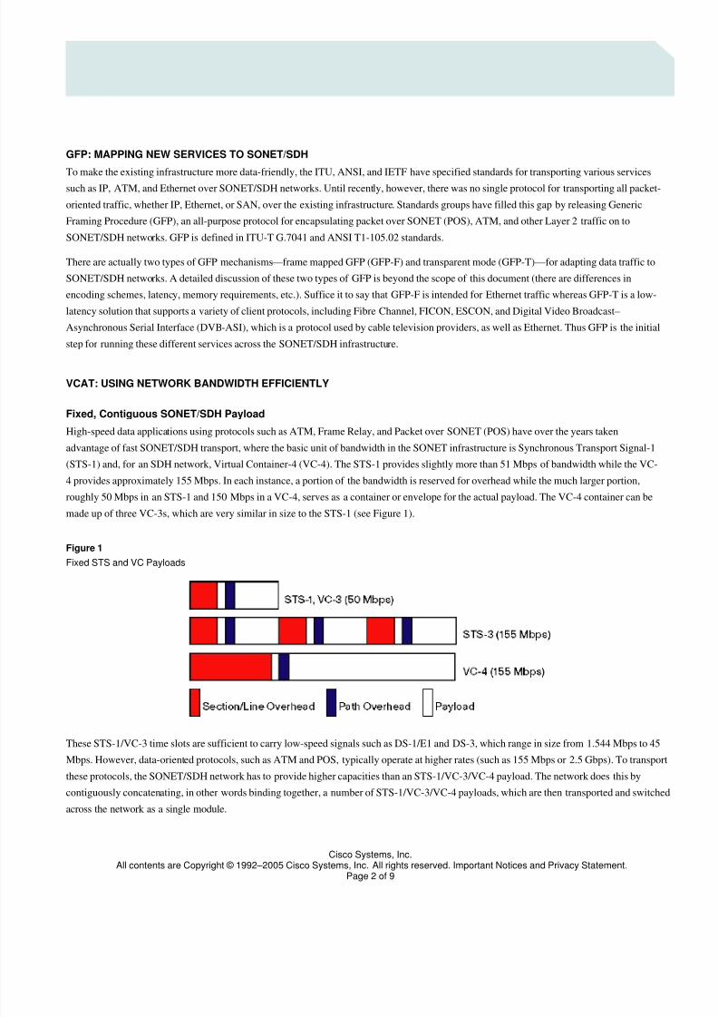
By mapping protocols such as ATM and POS to larger SONET/SDH payloads, the transport network is able to accommodate these protocols,
which, in fact, were developed to take advantage of SONET/SDH concatenation capabilities. Figure 2 shows examples of nonconcatenated and
concatenated 622-Mbps signals in SONET/SDH networks, with the c denoting a concatenated payload. Note that in SONET networks a
concatenated 622-Mbps signal is called an STS-12c; in SDH networks it is called a VC-4-4c, the first 4 representing the VC-4 frame format and
second 4 denoting the total bandwidth.
Figure 2
Contiguous Concatenation
Starting with STS-1/VC-4 time slots as the base unit of bandwidth, SONET/SDH concatenation scales in increments of three, the typically
supported concatenations being STS-3c/VC-4, STS-12c/VC-4-4c, STS-48c/VC-4-16c, and STS-192c/VC-4-64c.
With this typical or common concatenation, a circuit from one access device is simply mapped to another access device because all devices in
the path support the same concatenation scheme. Although many next-generation SONET/SDH devices support uncommon concatenation (for
instance, at 1.2-Gbps STS-24c/VC-4-8c to more efficiently map Gigabit Ethernet or 1-Gbps Fibre Channel to SONET/SDH payloads), there
still is an issue with existing Digital Crossconnect Systems (DCSs) that continue to play a role in the network core. Specifically, many access
rings have been built with next-generation devices, such as the Cisco ONS 15300 Series and the Cisco ONS 15454, and these access rings
interconnect to installed DCSs, which do not support cross-connection of an uncommon concatenated circuit, such as an STS-24c/VC-4-8c.
There are two possible solutions to this problem. The first would be to simply map the Ethernet or Fibre Channel traffic to a larger, commonly
concatenated payload across the entire span, in this case 2.5-Gbps STS-48c/VC-4-16c. Although this would allow for inter-ring traffic, it would
be a very inefficient use of bandwidth (Figure 3).

7/31/2019 Prod White Paper0900aecd802c8630
http://slidepdf.com/reader/full/prod-white-paper0900aecd802c8630 4/10
Cisco Systems, Inc.All contents are Copyright © 1992–2005 Cisco Systems, Inc. All rights reserved. Important Notices and Privacy Statement.
Page 4 of 9
Figure 3
Multiple-Ring Cross-Connection Using Large Concatenation
The second solution would be to aggregate smaller, uncommon concatenated flows, such as an STS-24c/VC-3-8c, into a larger, common
concatenated flow. For example, two Gigabit Ethernet signals (traffic A and traffic B) could be mapped to an STS-48c/VC-4-16c POS circuit
(traffic A+B in Figure 4). This method makes better use of network bandwidth, but the downside is that the cost of POS ports on aggregation
routers is much higher than Gigabit Ethernet or even 10-Gbps Ethernet ports because of pricier optics used for SONET/SDH and more stringent
timing requirements.
Figure 4
Multiple-Ring Cross-Connection Using the Aggregation Model

7/31/2019 Prod White Paper0900aecd802c8630
http://slidepdf.com/reader/full/prod-white-paper0900aecd802c8630 5/10
Cisco Systems, Inc.All contents are Copyright © 1992–2005 Cisco Systems, Inc. All rights reserved. Important Notices and Privacy Statement.
Page 5 of 9
Inefficiencies of Fixed Payloads and Contiguous Concatenation
Although contiguous concatenation offers the benefit of larger flows, there are two areas where the inefficiencies of fixed payloads and
contiguous concatenation result in wasted bandwidth.
Fragmented bandwidth deprives the carrier of using available network bandwidth. Even when well-understood rules are followed to avoid
bandwidth stranding, fragmented bandwidth can still happen. Moreover, the higher the line rate, the greater the chance of fragmented
bandwidth. When this occurs, established circuits have to be reprovisioned to make room for the new circuit, all of which takes time and
possibly a degradation or even interruption of customer service. With older systems it can takes hours or even a full day to establish a new
circuit when bandwidth is stranded in the network, which requires more time and effort from the service provider.
Figure 5 illustrates the problem of stranded bandwidth in an STS-12. Here, an STS-9 is in use and a new STS-3c needs to be inserted. Although
a sufficient number of STS-1 time slots are available, they are not contiguous, and so there is insufficient space to establish an STS-3c.
Figure 5Stranded Bandwidth in an STS-12
While stranded bandwidth might be avoidable, there is, however, no getting around the inefficiencies of fixed payloads and contiguous
concatenation when it comes to the transport of Ethernet and SAN traffic over SONET/SDH networks. Table 1 shows the inefficiencies of
transporting data protocols over SONET/SDH networks. VCAT overcomes these inefficiencies.
Table 1. Inefficiencies of Stranded Bandwidth
Service Bit Rate Utilization
Fast Ethernet 100 Mbps STS03c/VC-4 (67%)
Gigabit Ethernet 1000 Mbps STS-48c/VC-4-16c (42%)
Fiber Channel 200 Mbps STS-12c/VC-4-4c (33%)
Fiber Channel 1000 Mbps STS-48c/VC-4-16c (42%)
ESCON 200 Mbps STS-12c/VC-4-4c (33%)
7/31/2019 Prod White Paper0900aecd802c8630
http://slidepdf.com/reader/full/prod-white-paper0900aecd802c8630 6/10
Cisco Systems, Inc.All contents are Copyright © 1992–2005 Cisco Systems, Inc. All rights reserved. Important Notices and Privacy Statement.
Page 6 of 9
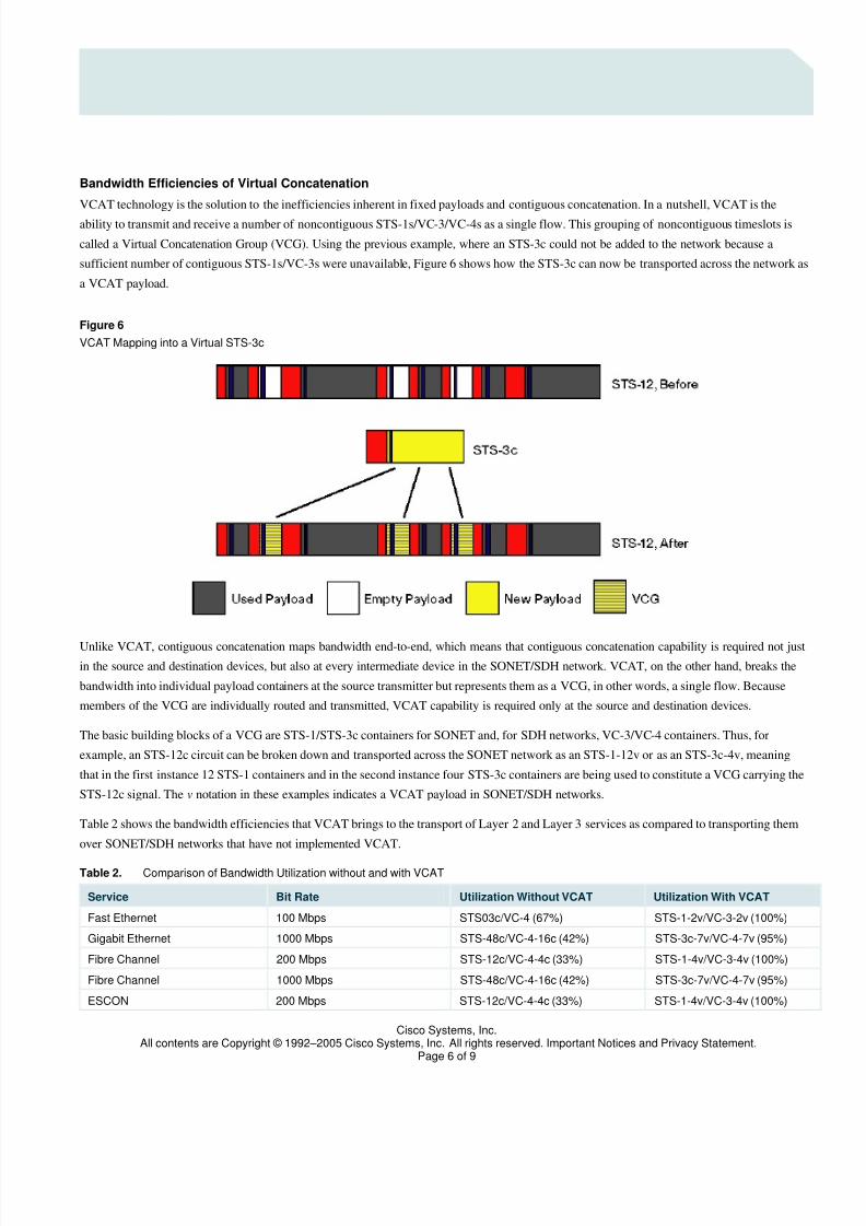
Bandwidth Efficiencies of Virtual Concatenation
VCAT technology is the solution to the inefficiencies inherent in fixed payloads and contiguous concatenation. In a nutshell, VCAT is the
ability to transmit and receive a number of noncontiguous STS-1s/VC-3/VC-4s as a single flow. This grouping of noncontiguous timeslots is
called a Virtual Concatenation Group (VCG). Using the previous example, where an STS-3c could not be added to the network because a
sufficient number of contiguous STS-1s/VC-3s were unavailable, Figure 6 shows how the STS-3c can now be transported across the network as
a VCAT payload.
Figure 6
VCAT Mapping into a Virtual STS-3c
Unlike VCAT, contiguous concatenation maps bandwidth end-to-end, which means that contiguous concatenation capability is required not just
in the source and destination devices, but also at every intermediate device in the SONET/SDH network. VCAT, on the other hand, breaks the
bandwidth into individual payload containers at the source transmitter but represents them as a VCG, in other words, a single flow. Because
members of the VCG are individually routed and transmitted, VCAT capability is required only at the source and destination devices.
The basic building blocks of a VCG are STS-1/STS-3c containers for SONET and, for SDH networks, VC-3/VC-4 containers. Thus, for
example, an STS-12c circuit can be broken down and transported across the SONET network as an STS-1-12v or as an STS-3c-4v, meaning
that in the first instance 12 STS-1 containers and in the second instance four STS-3c containers are being used to constitute a VCG carrying the
STS-12c signal. The v notation in these examples indicates a VCAT payload in SONET/SDH networks.
Table 2 shows the bandwidth efficiencies that VCAT brings to the transport of Layer 2 and Layer 3 services as compared to transporting them
over SONET/SDH networks that have not implemented VCAT.
Table 2. Comparison of Bandwidth Utilization without and with VCAT
Service Bit Rate Utilization Without VCAT Utilization With VCAT
Fast Ethernet 100 Mbps STS03c/VC-4 (67%) STS-1-2v/VC-3-2v (100%)
Gigabit Ethernet 1000 Mbps STS-48c/VC-4-16c (42%) STS-3c-7v/VC-4-7v (95%)
Fibre Channel 200 Mbps STS-12c/VC-4-4c (33%) STS-1-4v/VC-3-4v (100%)
Fibre Channel 1000 Mbps STS-48c/VC-4-16c (42%) STS-3c-7v/VC-4-7v (95%)
ESCON 200 Mbps STS-12c/VC-4-4c (33%) STS-1-4v/VC-3-4v (100%)

7/31/2019 Prod White Paper0900aecd802c8630
http://slidepdf.com/reader/full/prod-white-paper0900aecd802c8630 7/10
Cisco Systems, Inc.All contents are Copyright © 1992–2005 Cisco Systems, Inc. All rights reserved. Important Notices and Privacy Statement.
Page 7 of 9
For Ethernet services in particular, VCAT allows service providers to offer tiered Ethernet services with service-level agreements (SLAs).
Service providers can offer Ethernet services in 50-Mbps increments all the way up to Gigabit Ethernet because VCAT streams are comprised
of standard STS-1/VC-3 and STS-3c/VC-4 streams, which are supported by almost all SONET/SDH devices.
In fact, VCAT technology is capable of supporting even more granular Ethernet services. This is because what has been discussed so far is High
Order VCAT (HOVCAT), which noncontiguously concatenates relatively large containers (roughly 51 Mbps if STS-1/VC-3 are used and 155
Mbps if STS-3c/VC-4 are used). Low Order VCAT (LOVCAT) allows the transport and switching of sub-STS-1 payloads because the base
timeslot for LOVCAT in a SONET network is roughly 1.5 Mbps, referred to as Virtual Tributary 1.5 (VT1.5), while the corresponding timeslot
in an SDH network is 2 Mbps and is called VC-12. This more granular bandwidth provided by LOVCAT allows service providers to even more
efficiently use network capacity because they can now support a 1-Mbps Ethernet service using a VT1.5 or a VC-12, or a 10-Mbps Ethernet
service using seven VT1.5s or five VC-12s.
MODIFYING TRAFFIC PATTERNS WITHOUT DISRUPTION USING LCAS
Despite the many benefits of VCAT, service providers know all to well that customers’ bandwidth requirements are seldom static. When
customers’ needs for capacity change, they want the change to occur without any disruption in the service. Link Capacity Adjustment Scheme
(LCAS), a VCAT control mechanism, provides this capability. As a capacity-control mechanism, LCAS allows for the addition or reduction in
the payload capacity of a VCG to meet the bandwidth needs of the application. It does this whether bandwidth needs are being met through
implementation of HOVCAT, LOVCAT, or both. Individual payloads can be transparently added or removed in a VCG to resize bandwidth
without impacting service.
Without these capabilities, changing a customer’s bandwidth is always problematic for service providers. The best-case scenario for doing this
without disrupting service is to have sufficient capacity in the network for the old and new services to coexist during the reprovisioning process
In this situation, the service provider would do a “bridge-and-roll,” switching the customer from the old to the new circuit, a transition that
requires both circuits to be in service for a period of time. Without such overcapacity in the network, the customer could expect some service
outage during the “maintenance window” the service provider would need to tear down the old circuit before the new circuit could be
established. With VCAT and LCAS, bandwidth changes are not disruptive.
In addition to in-service resizing of bandwidth, LCAS offers other benefits:
• Dynamically replacing failed member links within a VCG without removing the entire VCG
• Unidirectional control of a VCG allows for asymmetric bandwidth
• Interworking of an LCAS transmitter with a non-LCAS receiver, and vice versa
• A broader range of SLAs because VCG bandwidth can be resized dynamically
• Aids in the creation of customer-based, on-demand services
From what has been discussed thus far, it is easy to see ways in which service providers can take advantage of VCAT and LCAS technologies
to efficiently and flexibly provide the required capacity for data services and to adjust bandwidth in-service to meet changing customer needs.
To illustrate the benefits of VCAT and LCAS, consider the following example: a metro service provider offering voice, data, and video services
leases an OC-48 (48 STS-1s) from a long-distance carrier to interconnect its metro rings across the country. Using VCAT/LCAS, the metro
service provider could transport different services through one or more VCGs made up of noncontiguous, nonstandard-size traffic payload. The
metro service provider would thus be optimizing the use of the OC-48 connection and possibly deferring the need for additional intercity
facilities. As the number of subscribers for the metro service provider’s IP service increases, using LCAS, the service provider could easily
modify the capacity partitioning between voice and IP services in favor of the latter because VCAT/LCAS would only be required at those
points at which the metro service provider interfaces with the backbone provider.

7/31/2019 Prod White Paper0900aecd802c8630
http://slidepdf.com/reader/full/prod-white-paper0900aecd802c8630 8/10
Cisco Systems, Inc.All contents are Copyright © 1992–2005 Cisco Systems, Inc. All rights reserved. Important Notices and Privacy Statement.
Page 8 of 9
Another example would be an end-to-end service provider that wants to use its SONET/SDH network to deliver optical Ethernet services.
Although the service provider might have a number of unused STS-3s/VC-4s in the network, these may be noncontiguous and therefore
unusable for Ethernet services. VCAT would allow the service provider to use these fragmented STS-3s/VC-4s to create a bandwidth pool for
Gigabit Ethernet service. As a result, the service provider would not have to immediately add new capacity to the network and would only have
to deploy VCAT capabilities at the edges of the metro network where Gigabit Ethernet service requirements exist.
Migrating from Voice to Data Services
As service providers move to address customers’ rapidly increasing need for Layer 2 and Layer 3 services, the Cisco ONS 15300 Series and
Cisco ONS 15454 are the MSPPs of choice. These platforms allow service providers to offer high-bandwidth services for advanced data
applications. For the fast growing IP/Ethernet services market, Cisco Carrier Ethernet (CE) Series interface cards for Cisco MSPPs allow
service providers to quickly provision point-to-point Ethernet services across SONET/SDH networks in the same way they currently provision
voice and time-division multiplexing (TDM) circuits.
The Cisco Multilayer Series (ML-Series) Ethernet interface cards are unique in the industry because they offer both Layer 2 switching and
Layer 3 routing, allowing service providers to support an intelligent multipoint network across a SONET/SDH infrastructure. With multilayer
intelligence, they can provide tiered services with SLAs to support advanced data applications such as VoIP, videoconferencing, video on
demand, television broadcasting, and VPNs.
CONCLUSION
SONET/SDH networks represent a significant investment for service providers, one that has proved its value over the years. New technologies
now allow service providers to bring greater efficiency and flexibility to these existing networks for data transport. Using GFP to map data
services to the SONET/SDH infrastructure is the first step in using this investment by making it data friendly. The injection of VCAT further
increases the value of the network by right-sizing network capacity to match native data rates and using what otherwise would be stranded
bandwidth. VCAT’s capability to provide very granular bandwidth for data services also allows service providers to offer a range of SLAs. The
addition of LCAS further enhances the value of VCAT by allowing service providers to make bandwidth adjustments to meet customers’changing needs in a manner transparent to customers.
Far from being short-term fixes, together these technologies offer nothing less than an evolutionary transformation of the SONET/SDH
network, one that allows service providers to simultaneously protect their investment in the existing transport infrastructure and meet the
challenge of delivering new services in an efficient and flexible manner.

7/31/2019 Prod White Paper0900aecd802c8630
http://slidepdf.com/reader/full/prod-white-paper0900aecd802c8630 9/10
Cisco Systems, Inc.All contents are Copyright © 1992–2005 Cisco Systems, Inc. All rights reserved. Important Notices and Privacy Statement.
Page 9 of 9
Corporate Headquarters
Cisco Systems, Inc.170 West Tasman DriveSan Jose, CA 95134-1706USAwww.cisco.comTel: 408 526-4000
800 553-NETS (6387)Fax: 408 526-4100
European Headquarters
Cisco Systems International BVHaarlerbergpark Haarlerbergweg 13-191101 CH AmsterdamThe Netherlandswww-europe.cisco.comTel: 31 0 20 357 1000Fax: 31 0 20 357 1100
Americas Headquarters
Cisco Systems, Inc.170 West Tasman DriveSan Jose, CA 95134-1706USAwww.cisco.comTel: 408 526-7660Fax: 408 527-0883
Asia Pacific Headquarters
Cisco Systems, Inc.168 Robinson Road#28-01 Capital TowerSingapore 068912www.cisco.comTel: +65 6317 7777Fax: +65 6317 7799
Cisco Systems has more than 200 offices in the following countries and regions. Addresses, phone numbers, and fax numbers are listed on theCisco Website at www.cisco.com/go/offices.
Argentina • Australia • Austria • Belgium • Brazil • Bulgaria • Canada • Chile • China PRC • Colombia • Costa RicaCroatia • Cyprus • Czech Republic • Denmark • Dubai, UAE • Finland • France • Germany • Greece • Hong Kong SARHungary • India • Indonesia • Ireland • Israel • Italy • Japan • Korea • Luxembourg • Malaysia • MexicoThe Netherlands • New Zealand • Norway • Peru • Philippines • Poland • Portugal • Puerto Rico • Romania • RussiaSaudi Arabia • Scotland • Singapore • Slovakia • Slovenia • South Africa • Spain • Sweden • Switzerland • TaiwanThailand • Turkey • Ukraine • United Kingdom • United States • Venezuela • Vietnam • Zimbabwe
All contents are Copyright © 1992–2005 Cisco Systems, Inc. All rights reserved. Cisco, Cisco Systems, and the Cisco Systems logo, are registered trademarks or trademarks of Cisco Systems, Inc. and/or its affiliates in the United States and certain other countries.
All other trademarks mentioned in this document or Website are the property of their respective owners. The use of the word partner does not imply a partnership relationshipbetween Cisco and any other company. (0502R) Pa/LW8630 06/05
Printed in USA

7/31/2019 Prod White Paper0900aecd802c8630
http://slidepdf.com/reader/full/prod-white-paper0900aecd802c8630 10/10
Cisco Systems, Inc.All contents are Copyright © 1992–2005 Cisco Systems, Inc. All rights reserved. Important Notices and Privacy Statement.
Page 10 of 9


