
IDX-OM-X004-B
PRODUCT NAME
Heatless Air Dryer
MODEL / Series ID20□-□02□
ID30□-□04□
ID40□-□04□
ID60□ -□06□
Please read this manual prior of using the air dryer. Keep the manual readily available for reference.
To Customers Thanks for purchasing SMC Heatless Air Dryer. This opertion manual must be read and understood throughoutly before handling. It provides all essential information for maximizing product operating efficiency, as well as, for safe and longer life span operation. For safety operation of SMC Refrigerated Air Dryer, read thoroughly and follow stated safety instructions, as well as regulation stated within ISO 4414*1 & JIS B 8370*2.
*1) ISO 4414: Pneumatic fluid power – General rules and safety requirements for systems and their components
*2) JIS B 8370: Pneumatic fluid power – General rules relating to systems This manual explains about installation and operation of the product. Only those who have thorough understanding of the fundamental operating procedure or have basic knowledge and skills of handling industrial product for the installation and operation of the product are qualified to perform installation and operation. The contents of the operation manual and the other documents attached to the product cannot become a part of the contract clause or cannot change and modify existing agreements, promises, and relationship. Any statements contained in the operation manual cannot be newly guaranteed and modify existing guarantee certificate. You are not allowed to copy any part of this operation manual for usage of third person without informing it to us beforehand.
Caution: Please understand that the contents of this operation manual are subject to changed without previous notice.
Heatless Air Dryer Table of Contents
Table of Contents - 1
Chapter i Safety Instructions
i - 1 Warning: Before Using Air Dryer .......................................................................... i - 1 i - 1 - 1 Meanings of signs: Danger, Warning, Caution .......................................................... i - 1
i - 2 Danger Classifications / Position of Danger warning label ............................ i - 3 i - 2 - 1 Danger Classifications ............................................................................................. i - 3
i - 2 - 2 Danger of Electricity ................................................................................................. i - 4
i - 2 - 3 Danger of Compressed Air Circuit ............................................................................ i - 4
i - 3 Limited warranty and Disclaimer / Compliance Requirements ...................... i - 5 Chapter 1 Name of each Parts
1 - 1 Name of each Parts ................................................................................................. 1 - 1 Chapter 2 Transportation / Installation
2 - 1 Transportation .......................................................................................................... 2 - 1 2 - 2 Installation ................................................................................................................ 2 - 1 2 - 2 - 1 Location .................................................................................................................. 2 - 1
2 - 2 - 2 Anchorage .............................................................................................................. 2 - 2
2 - 2 - 3 Air piping ................................................................................................................. 2 - 2
2 - 2 - 4 Electric wiring .......................................................................................................... 2 - 3
2 - 3 Cautions about Reinstallation .............................................................................. 2 - 5 Chapter 3 Operation / Shutdown
3 - 1 Check points before operation ............................................................................. 3 - 1 3 - 2 Operation .................................................................................................................. 3 - 1 3 - 3 Shutdown .................................................................................................................. 3 - 2 3 - 4 Check points before restart .................................................................................. 3 - 2 3 - 5 Precautions for long-term non-operation .......................................................... 3 - 2
Chapter 4 Maintenance 4 - 1 Daily inspection ....................................................................................................... 4 - 1 4 - 2 Periodical Maintenance ......................................................................................... 4 - 1 4 - 2 - 1 Exchange of absorbent................................................................................................... 4 - 1
4 - 2 - 2 Service parts .................................................................................................................. 4 - 2
4 - 2 - 3 Exchange of other parts.................................................................................................. 4 - 4
4 - 2 - 4 Check points book .......................................................................................................... 4 - 6
Chapter 5 Troubleshooting 5 - 1 Cause and countermeasure of errors ................................................................. 5 - 1 5 - 1 - 1 Failure diagnosis chart ................................................................................................... 5 - 1
5 - 1 - 2 Breakdown cause investigation points and measures ..................................................... 5 - 2
Chapter 6 References 6 - 1 Specifications .......................................................................................................... 6 - 1 6 - 2 Externals dimensional drawing ........................................................................... 6 - 2 6 - 3 Electrical Circuit ...................................................................................................... 6 - 3 6 - 4 Structure and operation principles ..................................................................... 6 - 4
Table of Contents
IDX-OM-X004 Heatless Air Dryer i Safety Instructions
i-1 Warning: Before Using Air Dryer i - 1
ID Series
Safety Instructions
Before use, read and comprehend important cautionary notification well on this operattion manual.
i-1 Warning: Before Using Air Dryer
In this chapter, the stated contents are especially about safety way to use the product. for customer. An Air Dryer is installed on the downstream of the air compressor to remove moisture. We, manufacturer, cannot take any responsibility if you use it for any other purpose. An Air Dryer works with high voltage and has some parts that gets hot or rotates during operation. Ask vendor if you need component replacement and servicing.
Not only people handle the air dryer but every people who perform maintenance on or do works related to it should read safety instructions on this operation manual before ha ndling. This operation manual is not a general safety manual which is practiced by safety training representatives. People who handle this product or work around it need to take training to comprehand inherent risks of it and master measures for safety. It is usually responsible for super visor to follow the safety instructions, but each operator or maintemance representative should do daily operations on their own head. Operators and maintemance representatives should take the safety of working place and work environment into account. It is necessary to think of the safety of working place and work environment for each task Take enough safety training before the operation training. It is very dangerous to do operation training without any safety training. Operation training must be paid attention to its safety.
i – 1 – 1 Meaning of Signs: Danger, Warning, Caution These safety instructions are intended to prevent hazardous situation and/or product damage. These instructions indicate the level of potential hazard by signs “Danger”, “Warning” or “Caution”. Contents with these signs state about important instructions concerning safety. Confirm where those signs are, and read and comprehend notices and cautionary notices well before handling.
“Danger”, “Warning” or “Caution” is the order of importance (Danger>Warning>Caution).
Followings are the meanings of those signs.
Danger Statements with the “Danger” sign explain about conditions in which there is a possible result of serious injury or loss of life if someone handles wrongly during operation or maintenance and did not follow the procedure to avoid danger.
i
IDX-OM-X004 Heatless Air Dryer i Safety Instructions
i-1 Warning: Before Using Air Dryer i - 2
ID Series
Warning Statements with the “Danger” sign explain about possibilities that can result in serious injury or loss of life if someone handle wrongly during operation or maintenance and did not follow the procedure to avoid danger.
Caution Statements with the “Danger” sign explain about possibilities that can result in injury or product damage if someone handles wrongly during operation or maintenance and did not follow the procedure to avoid danger.
IDX-OM-X004 Heatless Air Dryer i Safety Instructions
i-2 Danger Classifications / Position of Danger Warning Label i - 3
ID Series
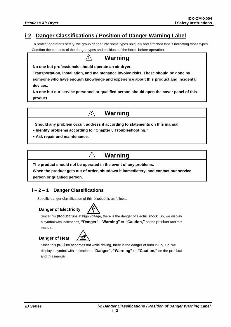
i-2 Danger Classifications / Position of Danger Warning Label To protect operator’s sefety, we group danger into some types uniquely and attached labels indicating those types. Comfirm the contents of the danger types and positions of the labels before operation.
Warning No one but professionals should operate an air dryer. Transportation, installation, and maintenance involve risks. These should be done by someone who have enough knowledge and experience about this product and incidental devices. No one but our service personnel or qualified person should open the cover panel of this product.
Warning Should any problem occur, address it according to statements on this manual.
Identify problems according to “Chapter 5 Troubleshooting.” Ask repair and maintenance.
Warning The product should not be operated in the event of any problems. When the product gets out of order, shutdown it immediatery, and contact our service person or qualified person.
i – 2 – 1 Danger Classifications
Specific danger classification of this product is as follows.
Danger of Electricity Since this product runs at hign voltage, there is the danger of electric shock. So, we display a symbol with indications, “Danger”, “Warning” or “Caution,” on the product and this manual.
Danger of Heat Since this product becomes hot while driving, there is the danger of burn injury. So, we display a symbol with indications, “Danger”, “Warning” or “Caution,” on the product and this manual.
IDX-OM-X004 Heatless Air Dryer i Safety Instructions
i-2 Danger Classifications / Position of Danger Warning Label i - 4
ID Series
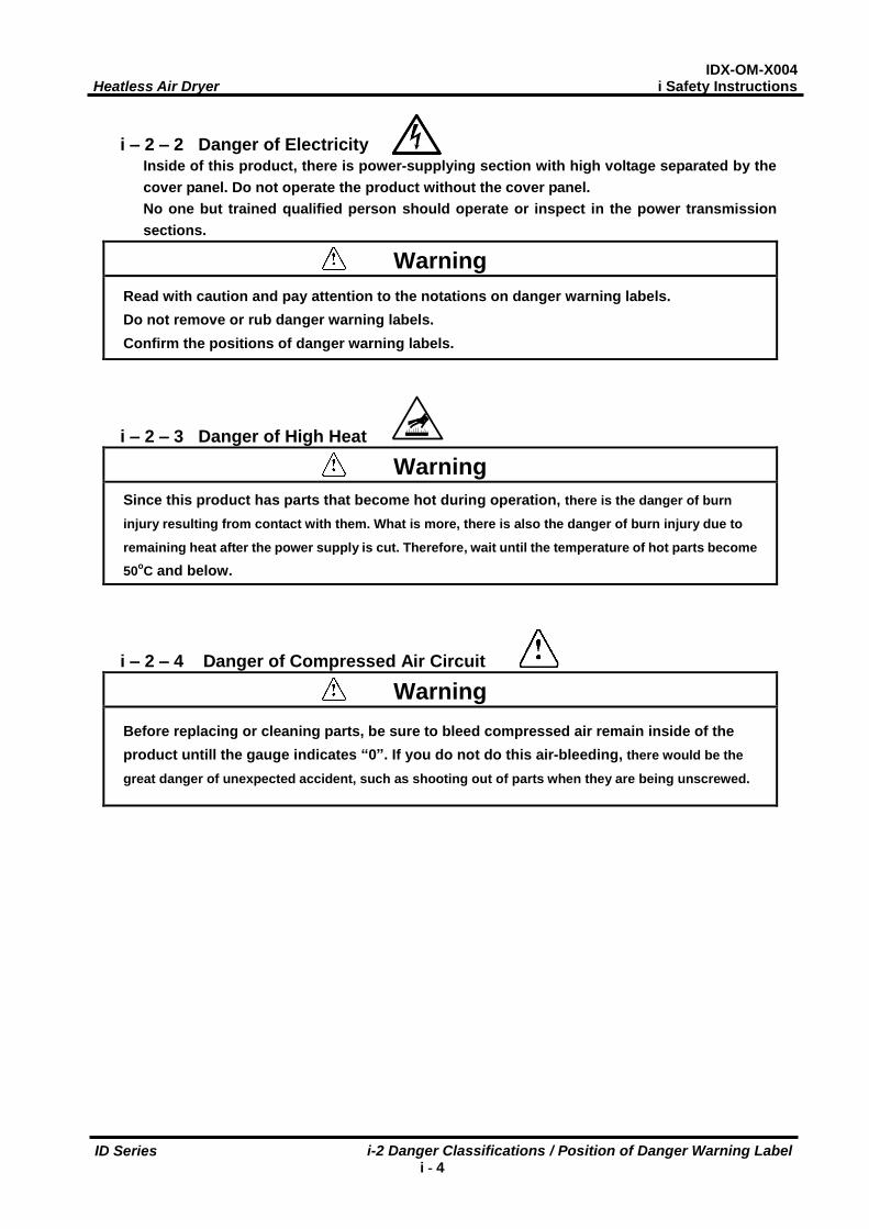
i – 2 – 2 Danger of Electricity
Inside of this product, there is power-supplying section with high voltage separated by the cover panel. Do not operate the product without the cover panel. No one but trained qualified person should operate or inspect in the power transmission sections.
Warning Read with caution and pay attention to the notations on danger warning labels. Do not remove or rub danger warning labels. Confirm the positions of danger warning labels.
i – 2 – 3 Danger of High Heat
Warning Since this product has parts that become hot during operation, there is the danger of burn
injury resulting from contact with them. What is more, there is also the danger of burn injury due to
remaining heat after the power supply is cut. Therefore, wait until the temperature of hot parts become
50oC and below.
i – 2 – 4 Danger of Compressed Air Circuit
Warning Before replacing or cleaning parts, be sure to bleed compressed air remain inside of the product untill the gauge indicates “0”. If you do not do this air-bleeding, there would be the
great danger of unexpected accident, such as shooting out of parts when they are being unscrewed.
IDX-OM-X004 Heatless Air Dryer i Safety Instructions
i-3 Limited warranty and Disclaimer / Compliance Requirements i – 5
ID Series
i-3 Limited warranty and Disclaimer / Compliance Requirements The product used subject to the following “Limited warranty and Disclaimer“ and “Compliance Requirements. Read and accept them before using the product.
Limited warranty and Disclaimer 1. The warranty period of the product is 1 year in service or 1.5 years after the product is delivered.
Also, the product may have specified durability, running distance or replacement parts. Please consult your nearest sales branch.
2. For any failure or damage reported within the warranty period which is clearly our responsibility, a replacement product or necessary parts will be provided. This limited warranty applies only to our product independently, and not to any other damage incurred due to the failure of the product.
3. Prior to using SMC products, please read and understand the warranty terms and disclaimers noted in the specified catalog for the particular products.
Compliance Requirements
1. The use of SMC products with production equipment for the manufacture of weapons of mass destruction (WMD) or other weapon is strictly prohibited.
2. The exports of SMC products or technology from one country to another are govemed by the relevant security laws and regulation of the countries involved in the transaction. Prior to the shipment of a SMC product of a SMC product to another country, assure that all local rules goveming that export are known and followed.
Caution
The Product is provided use in manufacturing industries. The product herein described is basically provided for peaceful use in manufacturing industries. If considering using the product in other industries, consult SMC beforehand and exchange specifications or a contact if necessary. If anything is unclear, contact your nearest sales branch.
Caution SMC products are not intended for use as instruments for legal metrology. Measurement instruments that SMC manufactures or sells have not been qualified by type approval tests relevant to the metrology (measurement) laws of each country. Therefore, SMC products cannot be used for business or certification ordained by the metrology (measurement) laws of each country.
IDX-OM-X004 Heatless Air Dryer 1 Name and Functions Parts
1-1 Name of each Parts 1 - 1
ID Series
1
Name of each Parts
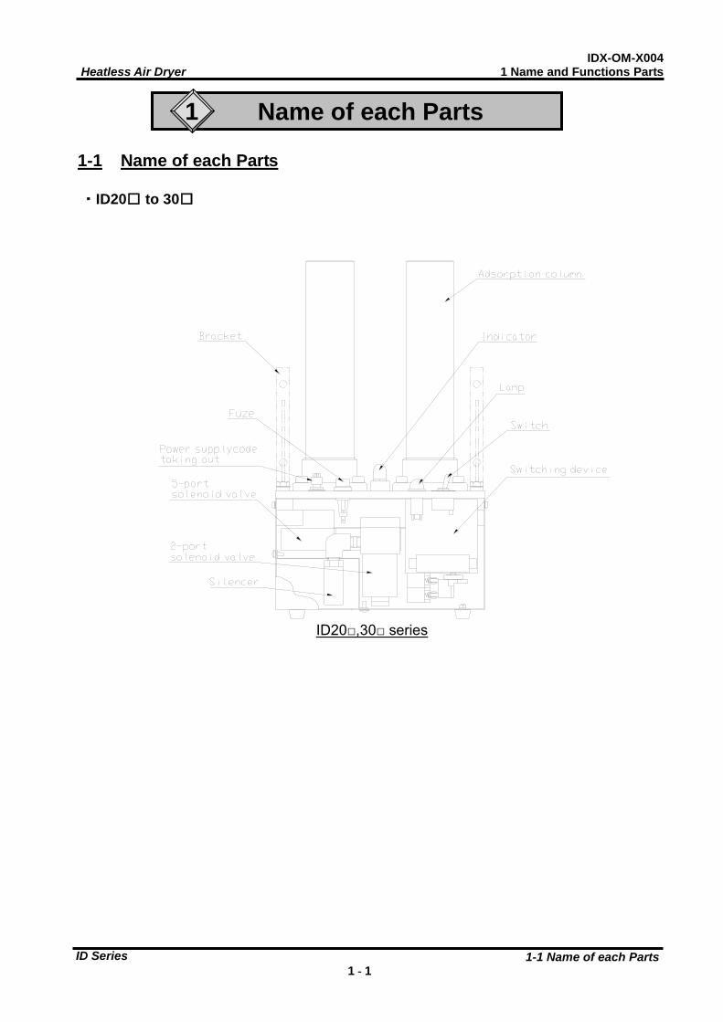
1-1 Name of each Parts ・ID20□ to 30□
ID20□,30□ series
IDX-OM-X004 Heatless Air Dryer 1 Name and Functions Parts
1-1 Name of each Parts 1 - 2
ID Series
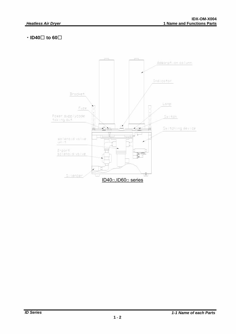
・ID40□ to 60□
ID40□,ID60□ series
IDX-OM-X004 Heatless Air Dryer 2 Transportation / Installation
2-1 Transportation 2 - 1
ID Series ID
2 Transportation / Installation
Warning Use the product in the right way. During Installation, operation, maintenance, and check, you should be careful in keeping the safety of human body.
Caution Transportation, installation, and maintenance including dangerous work must be done by a personnel who has enough knowledge and experience about the product and the sysytem.
2-1 Transportation When you transport the product, you should follow these instructions below.
You should uplift the product from the base surface with careful attention to prevent falling sideways and drop. Do not bring the product lying sideways. If you lay it sideways, it will be broken. Do not hang up the product. Do not transport the product with any part such as an air filter mounted on the fittings at the air inlet or outlet port
of the product. If it is unavoidable to transport the product with such a part mounted, support the part with a bracket to prevent the product from being affected by vibration during transportation.
Warning Those instructions above must be followed because the product is so heavy that it carries a great risk to transport. ID20* to 60* are 7 to 25kg . They must be transported by more than 2 person or transport it by truck.
2-2 Installation
2 - 2 - 1 Location
The product should not be used or stored in the circumstances as follows. Those circumstances will cause not only malfunction but also failures.
Environment where the product is exposed to rainwater, moisture vapor, salty water, oil and so on. Locations where dust or particles are. Locations where inflammable or explosive gas are. Locations where corrosive gas, solvent, combustible gas are. Locations that receive direct sunlight or where radiant heat is generated. Locations where ambient temperature is beyond following range:
On-stream: 5 to 50oC Storage: 0 to 50oC (when there is no drain water inside of the piping)
Locations where temperature changes rapidly. Locations where strong electromagnetic noise is generated.
(locations where electromagnetic field, surge is generated) Circumstances where static electricity is produced or discharged through the body of the product.
IDX-OM-X004 Heatless Air Dryer 2 Transportation / Installation
2-2 Installation 2 - 2
ID Series ID
Locations where strong high frequency wave is generated. Locations where danger of thunder is apparent. Locations by loading on vehicles, marine vessels, and so on. Locations whose altitude is higher than 2,000 meters. Circumstances where strong vibration or impact are transmitted. Circumstances where too much force and weight are put on the body of the product that causes it to deform. The air used to reproduce the absorbent and air which passed Indicator is exhausted outside of Heatless type
Air Dryer. Please use it in the place without the problem even if it exhausts it. Place without problem even if air is exhaust from outlet of product. Condition which has sudden pressure/flow rate changes.
Warning Do not use and store in environment having compressed air or ambinet atmosphere which includes the following substances. It could result in failure of the product and damage of components, which leads to injury.
- Corrosive gas, Organic solvent, Chemicals
2 - 2 - 2 Anchorage The air dryer should be installed on a vibration-free, stable, horizontal flat surface. Refer to “Chapter6 6-2 Externals dimensional drawing” for the dimensions.
2 - 2 - 3 Air piping Connection to the inlet and outlet of compressed air should be made removable by using union and so on. When mounting any part such as an air filter on the fitting at the compressed air inlet or outlet port, support the
part to prevent excessive force from being applied to the product Be careful not to let the vibration of the air compressor transmit. If the temperature of compressed air on the inlet side is higher than 50oC, place an aftercooler after the air
compressor. Or, make the temperature of the place where the air compressor is installed lower than 50oC. If the air supply makes high pressure fluctuation (pulsation), take any countermeasures such as installing air
tank. Flash the piping sufficiently in order to avoid any foreign substances such as dust, sealing tape, liquid gasket,
etc. when piping before piping connection. Foreign substances in the piping can cause malfunction or drainage failure.
Use pipes and fittings that have enough endurance against the operating pressure and temperature. And connect it firmly to prevent air leakage.
Please install it on the air pressure line with a supply capacity "Flowing quantity of the necessary exit air + flowing quantity of the reproduction air" above-mentioned.
Please install Mist separator (AM series) at upper stream of the ID. The capillary organization of the absorbent might be blockaded when the oil mist and the foreign particles exist in compress air, as the result, the adsorption ability decreases remarkably and at the same time the life of the absorbent is shortened. And also the inflow of drain should be avoided as it will make early deterioration of the absorbent. Please install Mist separator or Micro mist separator (AMD series) at the down stream when you want to avoid the contaminants with the powder etc. of the absorbent.
IDX-OM-X004 Heatless Air Dryer 2 Transportation / Installation
2-2 Installation 2 - 3
ID Series ID
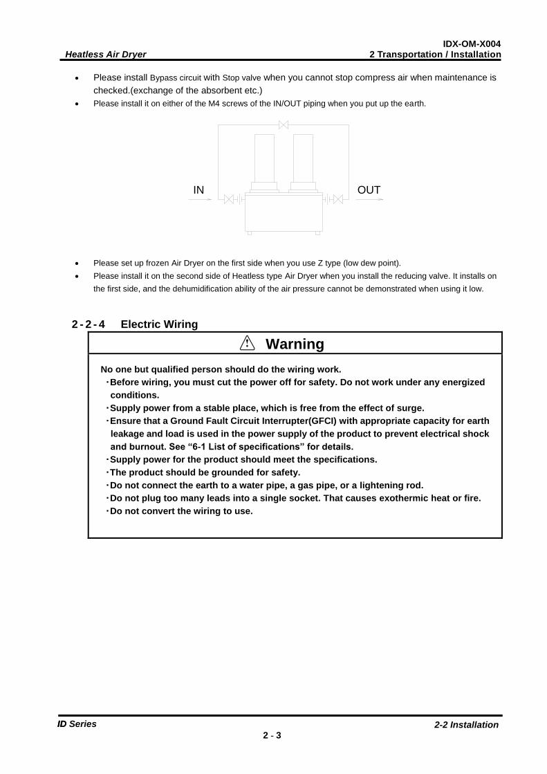
Please install Bypass circuit with Stop valve when you cannot stop compress air when maintenance is checked.(exchange of the absorbent etc.)
Please install it on either of the M4 screws of the IN/OUT piping when you put up the earth.
Please set up frozen Air Dryer on the first side when you use Z type (low dew point). Please install it on the second side of Heatless type Air Dryer when you install the reducing valve. It installs on
the first side, and the dehumidification ability of the air pressure cannot be demonstrated when using it low.
2 - 2 - 4 Electric Wiring
Warning No one but qualified person should do the wiring work. ・Before wiring, you must cut the power off for safety. Do not work under any energized conditions. ・Supply power from a stable place, which is free from the effect of surge. ・Ensure that a Ground Fault Circuit Interrupter(GFCI) with appropriate capacity for earth leakage and load is used in the power supply of the product to prevent electrical shock and burnout. See “6-1 List of specifications” for details. ・Supply power for the product should meet the specifications. ・The product should be grounded for safety. ・Do not connect the earth to a water pipe, a gas pipe, or a lightening rod. ・Do not plug too many leads into a single socket. That causes exothermic heat or fire. ・Do not convert the wiring to use.
IN OUT
IDX-OM-X004 Heatless Air Dryer 2 Transportation / Installation
2-2 Installation 2 - 4
ID Series ID
There are two methods depends on model (specified power)
ID200 to 600 / 201 to 601 (100/110V specified)
Insert the power plug into an outlet of 100/110V AC Do not extend the power cable using power strip and so on. That causes decrease of the voltage and
the product cannot be operated.
ID205 to 605 / 206 to 606 (200/220V specified)
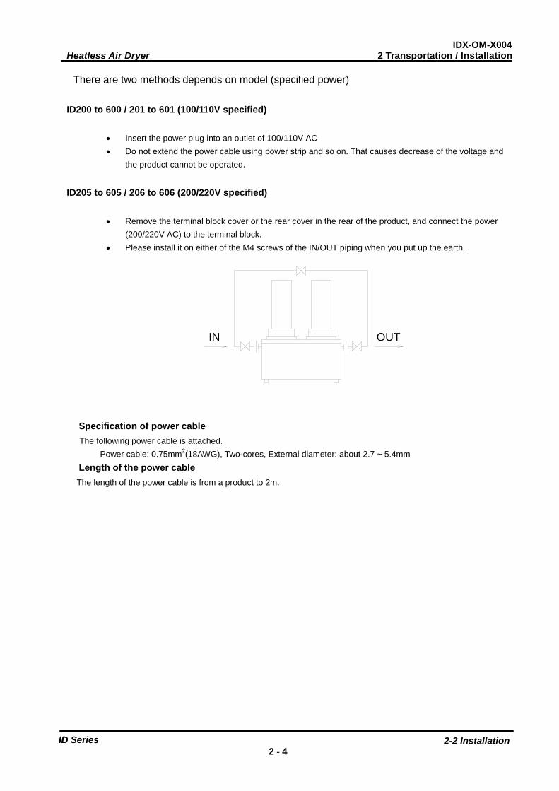
Remove the terminal block cover or the rear cover in the rear of the product, and connect the power (200/220V AC) to the terminal block.
Please install it on either of the M4 screws of the IN/OUT piping when you put up the earth.
Specification of power cable The following power cable is attached. Power cable: 0.75mm2(18AWG), Two-cores, External diameter: about 2.7 ~ 5.4mm Length of the power cable The length of the power cable is from a product to 2m.
IN OUT
IDX-OM-X004 Heatless Air Dryer 2 Transportation / Installation
2-3 Cautions about Reinstallation 2 - 5
ID Series ID
2-3 Cautions about Reinstallation
Caution No one but someone who has enough knowledge about the product and incidental devices should reinstall in another place. And following instructions must be executed.
If you move the product and reinstall it into another place after some operations (including trial running), instructions
that are not only following ones but also all of those in the chapter 2 should be followed.
Disassembly of the power cable Cut off the power source when you disassemble the power cable.
Warning No one but qualified personnel should do the electric wiring. Cut off the power supply for safety before the wiring. Do not work under energized condition.
Disassembly of the air piping
Warning No one but qualified personnel should do the air piping. Separate the compressor from the product for safety before removing the iping. Do not remove any piping when there is remaining compressed air pressure inside of it.
Remove the seal tape completely after detaching the piping. Remained tape will cause imperfect cooling
and failure by entering into the body of the product.
IDX-OM-X004 Heatless Air Dryer 3 Operation / Shutdown
3-1 Check points before operation 3 - 1
ID Series
3 Operation / Shutdown
Caution No one but someone who has enough knowledge and experience about the product and
incidental devices should operate or shut down the product.
3-1 Check points before operation Before a trial running, check following points.
Installed Condition By visual inspection check that the product is installed horizontally.
Make sure the product is fixed enough with anchor bolts.
Do not place heavy obstacles on the product and add unreasonable loading by piping and so on.
Wiring Connections Power cord, and the earth should be connected firmly.
Air Piping Make sure the piping for compressed air is connected correctly. Those valves of IN / Out side and bypass piping
of the product and of the bypass piping should be completely fasten.
3-2 Operation Start operation according to the procedure below.
Turn on the breaker of the main power supply. Then, turn on the illuminated switch.
Please turn on the power supply of the air dryer after it pressurizes it. If the power supply is turned on before it
pressurizes it (Especially, when pressure is low), abnormally a lot of flowing quantity of the reproduction air of
the starts might become bad the movement of the check valve.
When it does not use on, the absorbent might be damp. Please do the reproduction drive for about 20~30
minutes before closing and using the valve on the second side of the air dryer.
The adsorption column is cut right and left and alternately every about 150 seconds and changes. Please
confirm the change is regularly divided by the flow of the reproduction air.
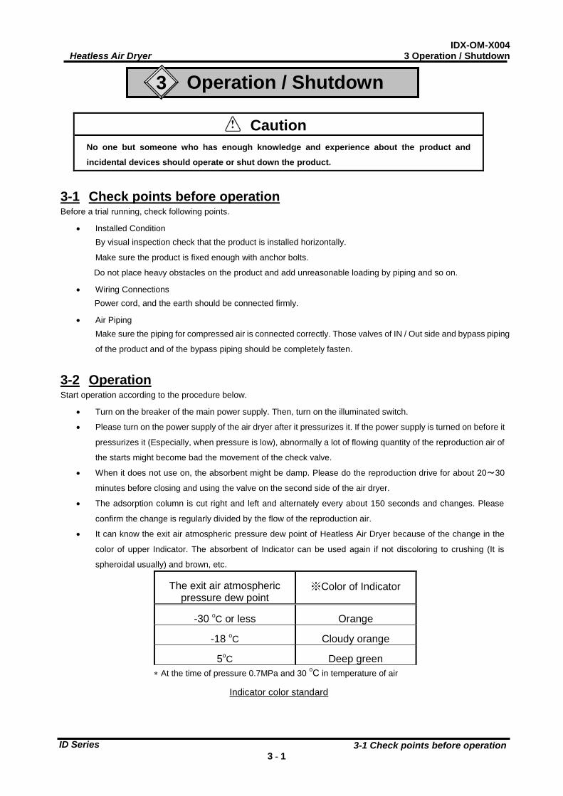
It can know the exit air atmospheric pressure dew point of Heatless Air Dryer because of the change in the
color of upper Indicator. The absorbent of Indicator can be used again if not discoloring to crushing (It is
spheroidal usually) and brown, etc.
The exit air atmospheric pressure dew point
※Color of Indicator
-30 oC or less Orange
-18 oC Cloudy orange
5oC Deep green At the time of pressure 0.7MPa and 30 oC in temperature of air
Indicator color standard
IDX-OM-X004 Heatless Air Dryer 3 Operation / Shutdown
3-3 Shutdown 3 - 2
ID Series
Caution ・Avoid frequent On/Off operation, which can cause troubles.
・Avoid using this product under the condition which has sudden pressure/flow rate changes.
Otherwise, drain (condensed water) may flow out to the secondary piping.
3-3 Shutdown Turn off the switch.
The lamp will go out and then, the operation will be stopped.
3-4 Check points before restart Check following points before you start operation. If any abnormalities occur, immediately stop the operation. Turn off the
illuminated switch of the product and then the breaker to the power supply.
There is no leakage of compressed air.
Compressed air pressure, temperature, flow rate, and ambient temperature meet the specifications.
There are no abnormal sound, vibration, or smelling.
3-5 Precautions for long-term non-operation If the product will not be operated for more than 24 hours, for example at the weekend, turn off the ILS (Switch
with lamp) or power supply, for energy saving and safety. It is also recommended to release the pressure.
Heatless Air Dryer 4 Maintenance
4-1 Daily Inspection 4 - 1
IDX-OM-X004
ID Series
4 Maintenance 4-1 Daily Inspection Check following points during usual operations. If you find some problems, immediately stop the operation and refer to “Chapter 5 Troubleshooting” as soon as possible.
There is no air leakage The running lamp is lighting during operation The adsorption column is cut right and left and alternately every about 150 seconds and changes. Please
confirm the change is regularly divided by the flow of the reproduction air. There is no abnormal sound or vibration coming up from the product. There are no abnormal smell or smoke coming up from the product.
4-2 Periodical Maintenance Please demonstrate the performance of Air Dryer enough, and check according to the check point’s book on
4-2-4 to prevent the breakdown beforehand. Moreover, please execute maintenance as follows.
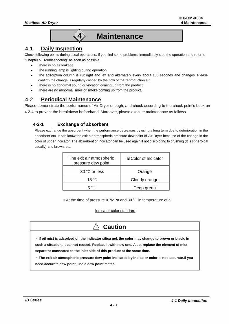
4-2-1 Exchange of absorbent Please exchange the absorbent when the performance decreases by using a long term due to deterioration in the absorbent etc. It can know the exit air atmospheric pressure dew point of Air Dryer because of the change in the color of upper Indicator. The absorbent of Indicator can be used again if not discoloring to crushing (It is spheroidal usually) and brown, etc.
The exit air atmospheric pressure dew point
※Color of Indicator
-30 oC or less Orange
-18 oC Cloudy orange
5 oC Deep green
At the time of pressure 0.7MPa and 30 oC in temperature of ai
Caution
・If oil mist is adsorbed on the indicator silica gel, the color may change to brown or black. In
such a situation, it cannot reused. Replace it with new one. Also, replace the element of mist
separator connected to the inlet side of this product at the same time.
・The exit air atmospheric pressure dew point indicated by indicator color is not accurate.If you
need accurate dew point, use a dew point meter.
Indicator color standard
Heatless Air Dryer 4 Maintenance
4-2 Periodical Maintenance 4 - 2
IDX-OM-X004
ID Series
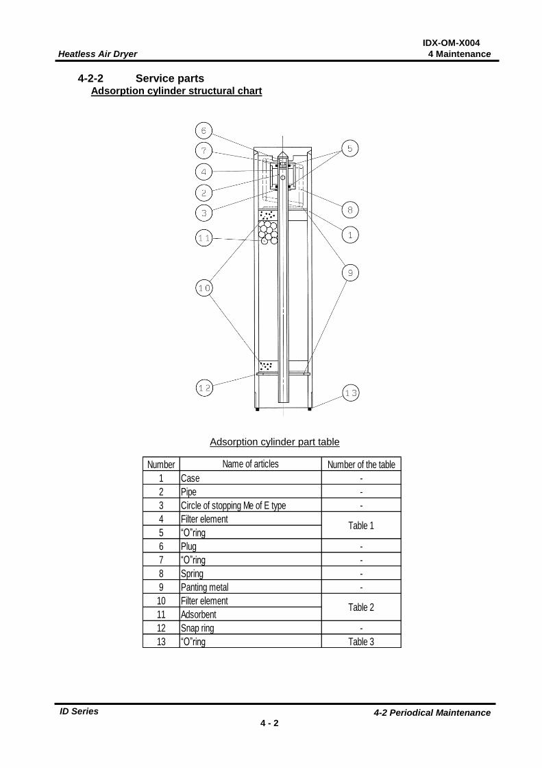
4-2-2 Service parts Adsorption cylinder structural chart
Adsorption cylinder part table
Number Number of the table1 Case -2 Pipe -3 -4 Filter element5 “O”ring
6 Plug -7 “O”ring -8 Spring -9 Panting metal -10 Filter element11 Adsorbent12 Snap ring -13 “O”ring Table 3
Name of articles
Table 1
Table 2
Circle of stopping Me of E type
Heatless Air Dryer 4 Maintenance
4-2 Periodical Maintenance 4 - 3
IDX-OM-X004
ID Series
Decomposition
1. Please pull out Stop valve of the piping line and pull out the pressure of shutting Air Dryer. Please turn the adsorption column counterclockwise after confirming pressure came off and remove. (Width of across flat ID40□:22,ID60□:24)
2. Please make the adsorption column upper and lower and inverted. (Threaded portion is done up.) 3. ⑫ please detach C type stop circle for the hole. It is convenient to use a special tool (Snap ring installation Pliers)
to detach C type stop circle for the hole. 4. ⑨ please detach Panting metal and ⑩ filter element. 5. ① please make the case inverted, and remove an inside absorbent. 6. ② please pull Pipe, and take out internal parts. 7. Please wash each part by Air blow. 8. ④ When the air filter has caused stopped up, it is necessary to exchange it. 9. ⑩ please exchange filter of ⑪ and ⑬“O”ring at each exchange of the absorbent.
Class addition
1. ④ please put ⑤“O”ring 2 in the ditch of the filter element. Please install this filter element in ②Pipe. 2. ① please put case and ⑧ Spring. 3. Please encase the pipe of clause 1. 4. ⑨ please put Panting metal and ⑩ filter element sequentially. 5. Please put a new ⑪ absorbent from the ditch of C type stop circle for the hole 10mm below. Please fill
the absorbent while lightly giving happen the vibration. When filling the adsorbent, please to come to the center ② pipe.
6. Please put a new ⑫ filter element and ⑬ Panting metal sequentially. 7. ⑭ please put C type stop circle for the hole in the ditch of ① case. 8. Please confirm the foreign body is not mixed in ②Pipe when the case is made inverted (Threaded
portion is done below). 9. ① Grease is spread on the threaded portion of the case, and the adsorption column must screw in the
main body.
Table 1 Replacement part
ID20* ID30* ID40* ID60*4 Filter element ID-S0055 ID-S0056 25 “O”ring KA00072 KA00074 4
quantityPurchase order number
ID-S0054KA00066
Number Name of articles
Table 2 Adsorbent set part
ID20* ID30* ID40* ID60*ID-200S ID-300S ID-400S ID-600S
ID-200Z ID-300Z ID-400Z ID-600Z
Number Name of articlesPurchase order number
quantity
10・11 Standard type 1(Filter element, Adsorbent, “O”ring)
10・11 1(Filter element, Adsorbent, “O”ring)
Low dew point type(ID*0*-**-Z)
Table 3 “O”ring
ID20* ID30* ID40* ID60*13 “O”ring KA00460 KA00462 KA00064 KA00455 2(Note)Note:
Number Name of articles Purchase order number quantity
Because O-ring in Table 3 is attached when Table 2 does the adsorbent setarrangements, the simulataneous arrangements are unnecessary.
Heatless Air Dryer 4 Maintenance
4-2 Periodical Maintenance 4 - 4
IDX-OM-X004
ID Series
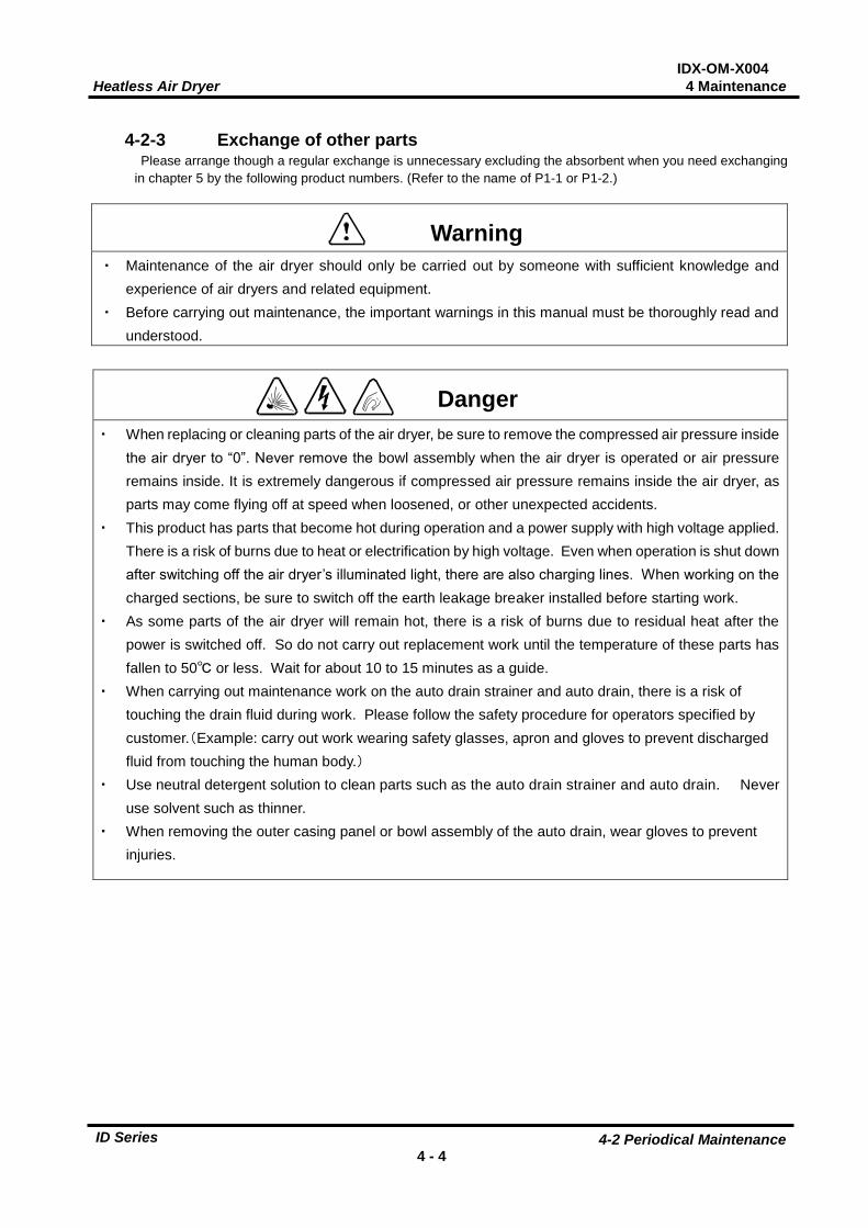
4-2-3 Exchange of other parts
Please arrange though a regular exchange is unnecessary excluding the absorbent when you need exchanging in chapter 5 by the following product numbers. (Refer to the name of P1-1 or P1-2.)
・ Maintenance of the air dryer should only be carried out by someone with sufficient knowledge and experience of air dryers and related equipment.
・ Before carrying out maintenance, the important warnings in this manual must be thoroughly read and understood.
・ When replacing or cleaning parts of the air dryer, be sure to remove the compressed air pressure inside the air dryer to “0”. Never remove the bowl assembly when the air dryer is operated or air pressure remains inside. It is extremely dangerous if compressed air pressure remains inside the air dryer, as parts may come flying off at speed when loosened, or other unexpected accidents.
・ This product has parts that become hot during operation and a power supply with high voltage applied. There is a risk of burns due to heat or electrification by high voltage. Even when operation is shut down after switching off the air dryer’s illuminated light, there are also charging lines. When working on the
charged sections, be sure to switch off the earth leakage breaker installed before starting work. ・ As some parts of the air dryer will remain hot, there is a risk of burns due to residual heat after the
power is switched off. So do not carry out replacement work until the temperature of these parts has fallen to 50℃ or less. Wait for about 10 to 15 minutes as a guide.
・ When carrying out maintenance work on the auto drain strainer and auto drain, there is a risk of touching the drain fluid during work. Please follow the safety procedure for operators specified by customer.(Example: carry out work wearing safety glasses, apron and gloves to prevent discharged fluid from touching the human body.)
・ Use neutral detergent solution to clean parts such as the auto drain strainer and auto drain. Never use solvent such as thinner.
・ When removing the outer casing panel or bowl assembly of the auto drain, wear gloves to prevent injuries.
Warning
Danger
Heatless Air Dryer 4 Maintenance
4-2 Periodical Maintenance 4 - 5
IDX-OM-X004
ID Series
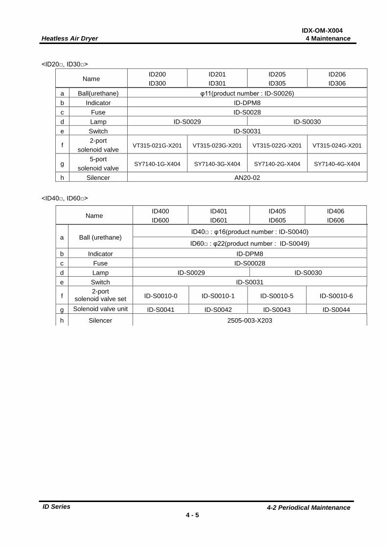
<ID20□, ID30□>
Name ID200 ID300
ID201 ID301
ID205 ID305
ID206 ID306
a Ball(urethane) φ11(product number : ID-S0026) b Indicator ID-DPM8 c Fuse ID-S0028 d Lamp ID-S0029 ID-S0030 e Switch ID-S0031
f 2-port
solenoid valve VT315-021G-X201 VT315-023G-X201 VT315-022G-X201 VT315-024G-X201
g 5-port
solenoid valve SY7140-1G-X404 SY7140-3G-X404 SY7140-2G-X404 SY7140-4G-X404
h Silencer AN20-02 <ID40□, ID60□>
Name ID400 ID600
ID401 ID601
ID405 ID605
ID406 ID606
a Ball (urethane) ID40□ : φ16(product number : ID-S0040)
ID60□ : φ22(product number : ID-S0049) b Indicator ID-DPM8 c Fuse ID-S00028 d Lamp ID-S0029 ID-S0030 e Switch ID-S0031
f 2-port
solenoid valve set ID-S0010-0 ID-S0010-1 ID-S0010-5 ID-S0010-6
g Solenoid valve unit ID-S0041 ID-S0042 ID-S0043 ID-S0044 h Silencer 2505-003-X203
Heatless Air Dryer 4 Maintenance
4-2 Periodical Maintenance 4 - 6
IDX-OM-X004
ID Series
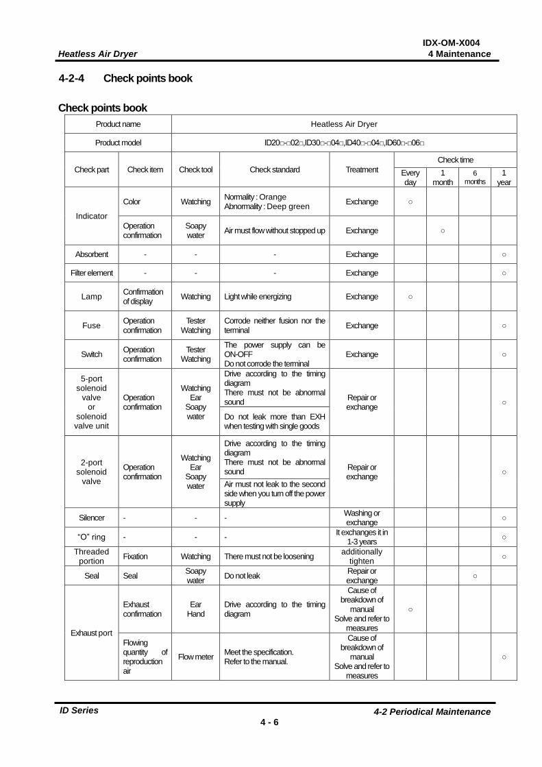
4-2-4 Check points book Check points book
Product name Heatless Air Dryer
Product model ID20□-□02□,ID30□-□04□,ID40□-□04□,ID60□-□06□
Check part Check item Check tool Check standard Treatment Check time
Every day
1 month
6 months
1 year
Indicator
Color Watching Normality : Orange Abnormality : Deep green Exchange ○
Operation confirmation
Soapy water Air must flow without stopped up Exchange ○
Absorbent - - - Exchange ○
Filter element - - - Exchange ○
Lamp Confirmation of display Watching Light while energizing Exchange ○
Fuse Operation confirmation
Tester Watching
Corrode neither fusion nor the terminal Exchange ○
Switch Operation confirmation
Tester Watching
The power supply can be ON-OFF Do not corrode the terminal
Exchange ○
5-port solenoid
valve or
solenoid valve unit
Operation confirmation
Watching Ear
Soapy water
Drive according to the timing diagram There must not be abnormal sound Repair or
exchange ○
Do not leak more than EXH when testing with single goods
2-port solenoid
valve
Operation confirmation
Watching Ear
Soapy water
Drive according to the timing diagram There must not be abnormal sound Repair or
exchange ○ Air must not leak to the second side when you turn off the power supply
Silencer - - - Washing or exchange ○
“O” ring - - - It exchanges it in 1-3 years ○
Threaded portion Fixation Watching There must not be loosening additionally
tighten ○
Seal Seal Soapy water Do not leak Repair or
exchange ○
Exhaust port
Exhaust confirmation
Ear Hand
Drive according to the timing diagram
Cause of breakdown of
manual Solve and refer to
measures
○
Flowing quantity of reproduction air
Flow meter Meet the specification. Refer to the manual.
Cause of breakdown of
manual Solve and refer to
measures
○
IDX-OM-X004 Heatless Air Dryer 5 Troubleshooting
5-1 Cause and countermeasure of errors 5 - 1
ID Series
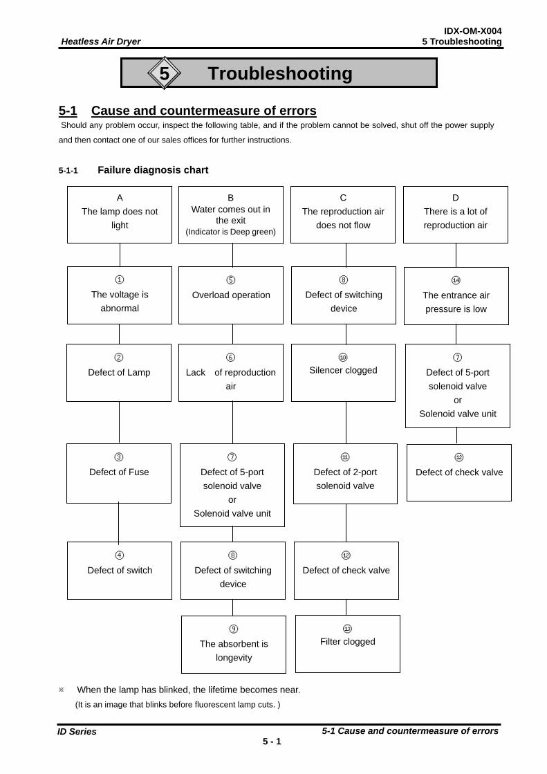
5
A The lamp does not
light
B Water comes out in
the exit (Indicator is Deep green)
C The reproduction air
does not flow
D There is a lot of reproduction air
①
The voltage is abnormal
⑤
Overload operation ⑭
The entrance air pressure is low
②
Defect of Lamp ⑥
Lack of reproduction air
⑩
Silencer clogged
③ Defect of Fuse
⑦
Defect of 5-port solenoid valve
or Solenoid valve unit
⑧
Defect of switching device
⑪
Defect of 2-port solenoid valve
⑦ Defect of 5-port solenoid valve
or Solenoid valve unit
⑫ Defect of check valve
④ Defect of switch
⑧ Defect of switching
device
⑨ The absorbent is
longevity
⑫
Defect of check valve
⑬
Filter clogged
Troubleshooting
5-1 Cause and countermeasure of errors Should any problem occur, inspect the following table, and if the problem cannot be solved, shut off the power supply
and then contact one of our sales offices for further instructions.
5-1-1 Failure diagnosis chart
※ When the lamp has blinked, the lifetime becomes near. (It is an image that blinks before fluorescent lamp cuts. )
IDX-OM-X004 Heatless Air Dryer 5 Troubleshooting
5-1 Cause and countermeasure of errors 5 - 2
ID Series
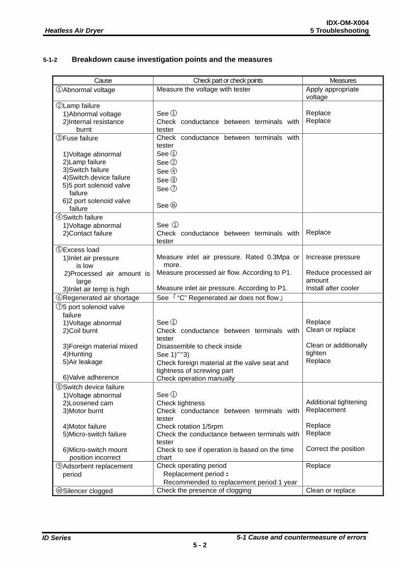
5-1-2 Breakdown cause investigation points and the measures
Cause Check part or check points Measures ①Abnormal voltage Measure the voltage with tester Apply appropriate
voltage ②Lamp failure 1)Abnormal voltage 2)Internal resistance
burnt
See ① Check conductance between terminals with tester
Replace Replace
③Fuse failure 1)Voltage abnormal 2)Lamp failure 3)Switch failure 4)Switch device failure
5)5 port solenoid valve failure 6)2 port solenoid valve failure
Check conductance between terminals with tester See ① See ② See ④ See ⑧ See ⑦ See ⑪
④Switch failure 1)Voltage abnormal 2)Contact failure
See ① Check conductance between terminals with tester
Replace
⑤Excess load 1)Inlet air pressure
is low 2)Processed air amount is
large 3)Inlet air temp is high
Measure inlet air pressure. Rated 0.3Mpa or
more. Measure processed air flow. According to P1. Measure inlet air pressure. According to P1.
Increase pressure Reduce processed air amount Install after cooler
⑥Regenerated air shortage See 「“C” Regenerated air does not flow」 ⑦5 port solenoid valve
failure 1)Voltage abnormal 2)Coil burnt
3)Foreign material mixed 4)Hunting 5)Air leakage 6)Valve adherence
See ① Check conductance between terminals with tester Disassemble to check inside See 1)~3) Check foreign material at the valve seat and tightness of screwing part Check operation manually
Replace Clean or replace Clean or additionally tighten Replace
⑧Switch device failure 1)Voltage abnormal
2)Loosened cam 3)Motor burnt
4)Motor failure 5)Micro-switch failure
6)Micro-switch mount
position incorrect
See ① Check tightness Check conductance between terminals with tester Check rotation 1/5rpm Check the conductance between terminals with tester Check to see if operation is based on the time chart
Additional tightening Replacement Replace Replace Correct the position
⑨Adsorbent replacement period
Check operating period Replacement period:
Recommended to replacement period 1 year
Replace
⑩Silencer clogged Check the presence of clogging Clean or replace
IDX-OM-X004 Heatless Air Dryer 5 Troubleshooting
5-1 Cause and countermeasure of errors 5 - 3
ID Series
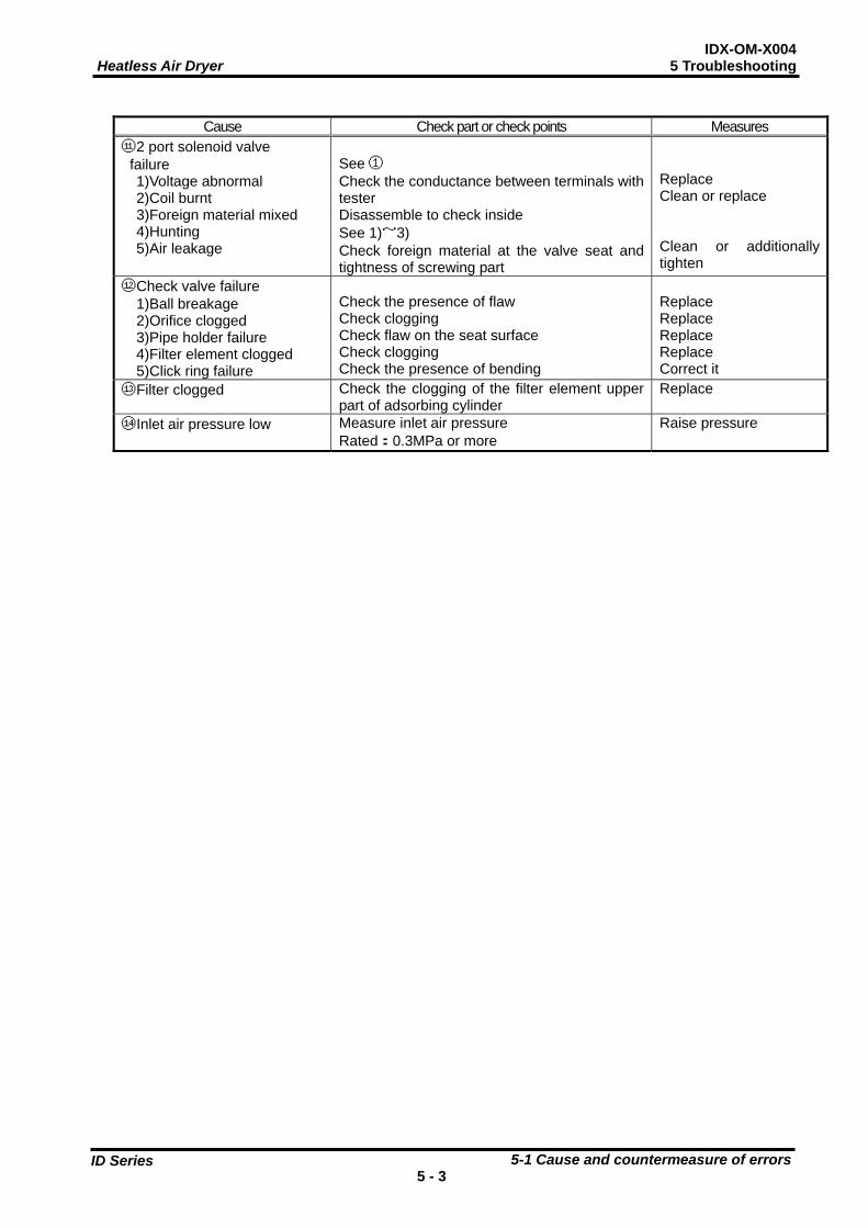
Cause Check part or check points Measures
⑪2 port solenoid valve failure 1)Voltage abnormal 2)Coil burnt 3)Foreign material mixed 4)Hunting 5)Air leakage
See ① Check the conductance between terminals with tester Disassemble to check inside See 1)~3) Check foreign material at the valve seat and tightness of screwing part
Replace Clean or replace Clean or additionally tighten
⑫Check valve failure 1)Ball breakage 2)Orifice clogged 3)Pipe holder failure 4)Filter element clogged 5)Click ring failure
Check the presence of flaw Check clogging Check flaw on the seat surface Check clogging Check the presence of bending
Replace Replace Replace Replace Correct it
⑬Filter clogged Check the clogging of the filter element upper part of adsorbing cylinder
Replace
⑭Inlet air pressure low Measure inlet air pressure Rated:0.3MPa or more
Raise pressure
IDX-OM-X004 Heatless Air Dryer 6 References
6-1 Specifications 6 - 1
ID Series
6
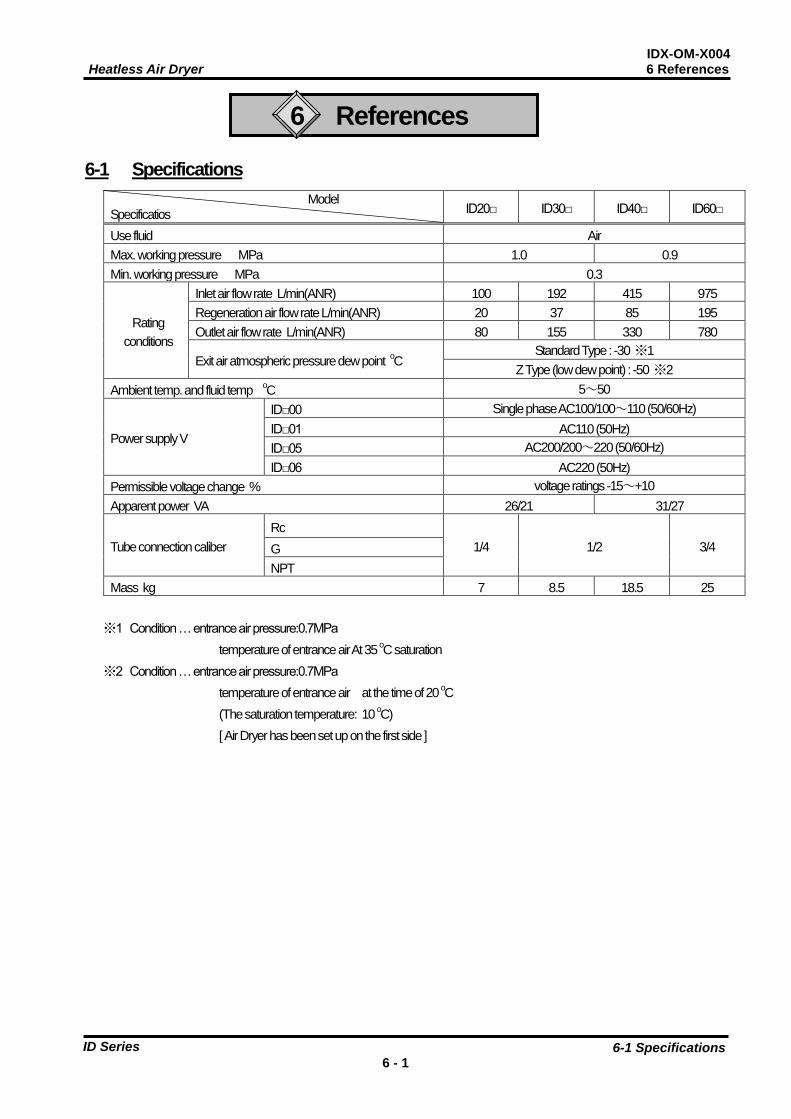
References 6-1 Specifications
Model Specificatios ID20□ ID30□ ID40□ ID60□
Use fluid Air Max. working pressure MPa 1.0 0.9 Min. working pressure MPa 0.3
Rating conditions
Inlet air flow rate L/min(ANR) 100 192 415 975 Regeneration air flow rate L/min(ANR) 20 37 85 195 Outlet air flow rate L/min(ANR) 80 155 330 780
Exit air atmospheric pressure dew point oC Standard Type : -30 ※1
Z Type (low dew point) : -50 ※2 Ambient temp. and fluid temp oC 5~50
Power supply V
ID□00 Single phase AC100/100~110 (50/60Hz) ID□01 AC110 (50Hz) ID□05 AC200/200~220 (50/60Hz) ID□06 AC220 (50Hz)
Permissible voltage change % voltage ratings -15~+10 Apparent power VA 26/21 31/27
Tube connection caliber Rc
1/4 1/2 3/4 G NPT
Mass kg 7 8.5 18.5 25
※1 Condition … entrance air pressure:0.7MPa temperature of entrance air At 35 oC saturation
※2 Condition … entrance air pressure:0.7MPa temperature of entrance air at the time of 20 oC (The saturation temperature: 10 oC) [ Air Dryer has been set up on the first side ]
IDX-OM-X004 Heatless Air Dryer 6 References
6-1 Specifications 6 - 2
ID Series
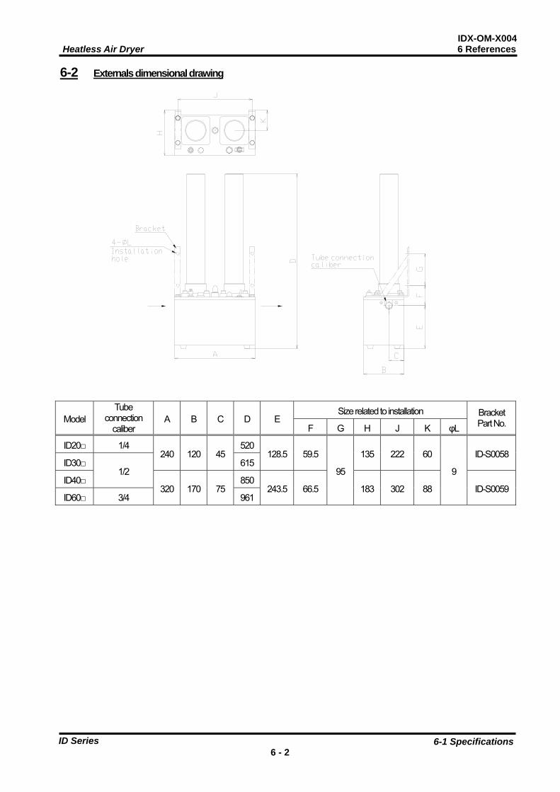
6-2 Externals dimensional drawing
Model Tube
connection caliber
A B C D E Size related to installation Bracket
Part No. F G H J K φL
ID20□ 1/4 240 120 45
520128.5 59.5
95
135 222 60
9
ID-S0058ID30□
1/2 615
ID40□ 320 170 75
850243.5 66.5 183 302 88 ID-S0059
ID60□ 3/4 961
IDX-OM-X004 Heatless Air Dryer 6 References
6-3 Electric circuit chart 6 - 3
ID Series
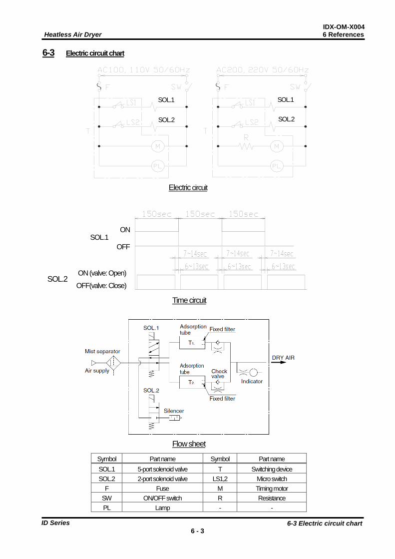
6-3 Electric circuit chart
Symbol Part name Symbol Part name SOL.1 5-port solenoid valve T Switching device SOL.2 2-port solenoid valve LS1,2 Micro switch
F Fuse M Timing motor SW ON/OFF switch R Resistance PL Lamp - -
Electric circuit
SOL.1
SOL.2
SOL.1
SOL.2
Flow sheet
Time circuit
ON
OFF
ON (valve: Open) OFF(valve: Close)
SOL.1
SOL.2
IDX-OM-X004 Heatless Air Dryer 6 References
6-4 Structure and operation principles 6 - 4
ID Series
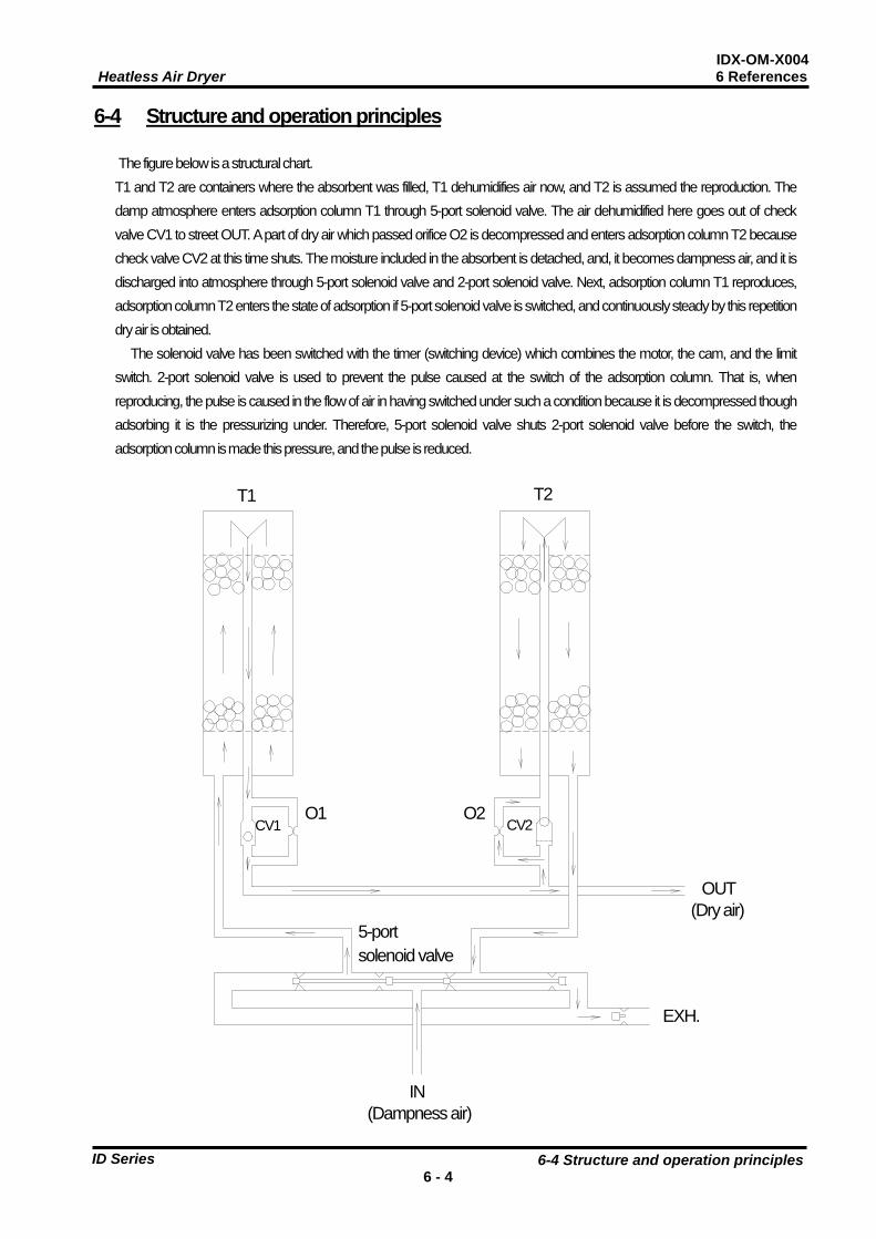
6-4 Structure and operation principles
The figure below is a structural chart. T1 and T2 are containers where the absorbent was filled, T1 dehumidifies air now, and T2 is assumed the reproduction. The damp atmosphere enters adsorption column T1 through 5-port solenoid valve. The air dehumidified here goes out of check valve CV1 to street OUT. A part of dry air which passed orifice O2 is decompressed and enters adsorption column T2 because check valve CV2 at this time shuts. The moisture included in the absorbent is detached, and, it becomes dampness air, and it is discharged into atmosphere through 5-port solenoid valve and 2-port solenoid valve. Next, adsorption column T1 reproduces, adsorption column T2 enters the state of adsorption if 5-port solenoid valve is switched, and continuously steady by this repetition dry air is obtained.
The solenoid valve has been switched with the timer (switching device) which combines the motor, the cam, and the limit switch. 2-port solenoid valve is used to prevent the pulse caused at the switch of the adsorption column. That is, when reproducing, the pulse is caused in the flow of air in having switched under such a condition because it is decompressed though adsorbing it is the pressurizing under. Therefore, 5-port solenoid valve shuts 2-port solenoid valve before the switch, the adsorption column is made this pressure, and the pulse is reduced.
T2 T1
O1 O2 CV1 CV2
5-port solenoid valve
EXH.
OUT (Dry air)
(Dampness air) IN
Akihabara UDX 15F, 4-14-1, Sotokanda, Chiyoda-ku, Tokyo 101-0021, JAPAN Tel: +81 3 5207 8249 Fax: +81 3 5298 5362 URL: https://www.smcworld.com Specifications are subject to change without prior notice and any obligation the part of the manufacturer. 2021 SMC Corporation All Rights Reserved
Revision history Rev A:Feb.2021. Rev B:Aug.2021


