

38MHROutdoor Unit Single Zone Ductless SystemSizes 09 to 24
Product Data
NOTE: Images are for illustration purposes only. Actual modelsmay differ slightly.
INDUSTRY LEADING FEATURES / BENEFITS
A PERFECT BALANCE BETWEENBUDGET LIMITS, ENERGY SAVINGS ANDCOMFORT.The 38MHR series ductless systems are a matched combination ofan outdoor condensing unit and an indoor fan coil unit connectedonly by refrigerant tubing and wires.
The ductless system permits creative solutions to design problemssuch as:
� Add−ons to current space (an office or family roomaddition)
� Special space requirements
� When changes in the load cannot be handled by theexisting system
� When adding air conditioning to spaces that are heatedby hydronic or electric heat and have no ductwork
� Historical renovations or any application wherepreserving the look of the original structure is essential.
The ideal compliment to your ducted system when it is impracticalor prohibitively expensive to use ductwork.The compact indoor fan coil units take up very little space in theroom and do not obstruct windows. The fan coils are attractivelystyled to blend with most room decors. Advanced systemcomponents incorporate innovative technology to provide reliablecooling performance at low sound levels.

2
Inverter TechnologyThe inverter driven compressor is designed to run at various inputpower frequencies (Hz) which controls the compressor’s motorspeed.Even Temperature – The control package, including the inverter,monitors the outdoor and indoor temperatures as they relate to theselected indoor set point and adjusts the compressor speed to matchthe load and keep the system operating continuously rather thancycling and creating temperature swings. This translates to highercomfort levels for the occupants.Rapid Pull Down/Warm−Up – Comfort is increased by theinverter system’s ability to ramp up the compressor speed enablingthe system to reach the user selected room temperature set pointquicker.
Humidity Control – Running the system for longer periods andcontinuously varying the compressor speed enhances the humiditycontrol.
Individual Room ComfortMaximum comfort is provided because each space can becontrolled individually based on the usage pattern.
Low Sound LevelsWhen noise is a concern, ductless systems are the answer. Theindoor units are whisper quiet. There are no compressors indoors,either in the conditioned space or directly over it, and there is noneof the noise usually generated by air being forced through theductwork.
When sound ordinances and proximity to neighbors demand quietoperation, this outdoor unit is the right choice. With the invertertechnology, these units run at lower speeds most of the timeresulting in reduced sound levels.
Inverter Technology – Enhanced EconomicalOperationDuctless systems are inherently economical to operate. Individualrooms are heated or cooled only when required, and since the air isdelivered directly to the space, there is no need to use additionalenergy to move the air in the ductwork. This economical operationis enhanced further when the inverter system output matches theload resulting in a more efficient system.
Easy−To−Use ControlsThe systems have microprocessor−based controls to provide theultimate in comfort and efficiency. The user friendly wired andwireless remote controls provide the interface between the user andthe unit.
Secure OperationIf security is an issue, outdoor and indoor units are connected onlyby refrigerant piping and wiring to prevent intruders from crawlingthrough ductwork or wall openings. In addition, since the outdoorunit can be installed close to an outside wall, coils are protectedfrom vandals and severe weather.
Fast InstallationThis compact ductless system is simple to install. Only wires andpiping need to run between the indoor and outdoor units. Theseunits are fast and easy to install ensuring minimal disruption tocustomers in homes or the workplace. This makes these systemsthe equipment of choice for retrofit applications.
Simple Servicing and MaintenanceRemoving the top panel of the outdoor unit provides immediateaccess to the control compartment, providing the service technicianaccess to the diagnostic LEDs to facilitate the troubleshootingprocess. In addition, the draw−thru design of the outdoor unitmeans that dirt accumulates on the outside surface of the coil. Coilscan be cleaned quickly from the inside using a pressure hose anddetergent.On the indoor units, service and maintenance expense is reduceddue to the permanent easy to clean filters. Also, error codes aredisplayed on the front panel to alert the user to certain systemmalfunctions
Built−in ReliabilityDuctless system indoor and outdoor units are designed to provideyears of trouble−free operation.
Both the indoor and outdoor units are well protected. Wheneverthe microprocessor detects abnormal conditions, the unit stops andan error code appears.
Inverter systems provide additional reliability due to the soft start.This refers to the ability of the inverter to start the compressormotor using reduced voltage and reduced current. This feature isbeneficial from an electrical standpoint (eliminates current spikes)as well as an overall reliability standpoint due to reduced stress onall associated system components.
Agency ListingsAll systems are listed with AHRI (Air conditioning, Heating, andRefrigeration Institute) and are ETL certified per UL 1995standard.

3
MODEL NUMBER NOMENCLATURE
QR A
SYSTEM TYPEC = COOLING ONLYQ = HEAT PUMP
UNIT TYPER = OUTDOOR UNIT
NOT USED
OUTDOOR UNIT
38 MH 309
38 = OUTDOOR UNIT
MH = MODEL
VOLTAGE1 =115-1-603 = 208/230-1-60
NOMINAL CAPACITY09 - 3/4 TON12 - 1 TON18 - 1-1/2 TONS 24 - 2 TONS
MAXIMUM NUMBER OF FAN COIL UNITS THATCAN BE CONNECTED TO THE OUTDOOR UNITA=1:1
- -
Use of the AHRI CertifiedTM Mark indicates amanufacturer’s participation in the program For verification of certification for individual products, go to www.ahridirectory.org.

4
STANDARD FEATURES AND ACCESSORIESEase Of Installation
Low Voltage Controls S
Comfort Features
Microprocessor Controls S
Auto Restart Function S
Auto Changeover SEnergy Saving Features
Inverter Driven Compressor S
46°F Heating Mode (Heating Setback) SSafety And Reliability
3 Minute Time Delay For Compressor S
High Compressor Discharge Temperature S
Low Voltage Protection S
Compressor Overload Protection S
Compressor Over Current Protection S
IPM Module Protection S
Condenser High Temp Protection in Cooling Mode S
Aluminum Blue Hydrophilic pre-coated fins S
Ease Of Service And Maintenance
Diagnostics S
Liquid Line Pressure Taps S
Application Flexibility
Crankcase Heater SLegendS StandardA Accessory
OUTDOOR UNITSCrankcase HeaterThe crankcase heater is standard on all unit sizes. Heater clampsmust be placed around the compressor oil stump.

5
DIMENSIONS − OUTDOOR
CoolingOnly
System Size Height (H) in. (mm) Width (W) in. (mm) Depth (D) in. (mm) Weight-Net lbs. (kg)
9K (115) 21.85(555) 30.31(770) 11.81(300) 57.3(26)
12K (115V) 21.85(555) 30.31(770) 11.81(300) 57.8(26.2)
9K (208/230V) 21.85(555) 30.31(770) 11.81(300) 54.7(24.8)
12K (208/230V) 21.85(555) 30.31(770) 11.81(300) 53.8(24.4)
18K (208/230V) 21.81(554) 31.50(800) 13.11(333) 70.1(31.8)
24K (208/230V) 27.64(702) 33.27(845) 14.29(363) 88.6(40.2)
HeatPump
System Size Height (H) in. (mm) Width (W) in. (mm) Depth (D) in. (mm) Weight-Net lbs. (kg)
9K (115) 21.85(555) 30.31(770) 11.81(300) 61.5(27.9)
12K (115V) 21.85(555) 30.31(770) 11.81(300) 65.0(29.5)
9K (208/230V) 21.85(555) 30.31(770) 11.81(300) 57.1(25.9)
12K (208/230V) 21.85(555) 30.31(770) 11.81(300) 60.6(27.5)
18K (208/230V) 21.81(554) 31.50(800) 13.11(333) 94.6(42.9)
24K (208/230V) 27.64(702) 33.27(845) 14.29(363) 105.2(47.7)
19.17(487) W1
2.76(70) W
11
.73
(298)
21
.85
(555)
11.81(300) D
H
0.4
7(1
2)
2.3
6(6
0)
3.6
6(9
3)
H1
H2
D1
30.31(770) W
30.66(779) W3
13
.07
(322)
D2
0.98(25) B1
3.5
4(9
0)
B2
2.42(61.5) A2
0.47(12) A1
R0.
24(6
)
11
.26
(286)
D3
Unit: inch(mm)
Fig. 1 – Sizes 9K and 12K

6
DIMENSIONS − OUTDOOR (CONT)
31.50 (800)
20.24 (514)21
.81
(554
)
2.36
(60)
3.37
(85.
5)
13.3
9 (3
40)
0.47
(12)
12.2
4 (3
11)
12.8
0 (3
25)
13.11 (333)
2.76 (7 0)
H
H1
H2
D1D2 D3
2.43 (6 1.8)
4.17
(106
)
0.87 (2 2)R 0.79 (R 20)
R 0.24 (R 6)
2.43 (6 1.6)
D
W
W1
W2
B1
B2
A2
A1
Unit: inch(mm)Fig. 2 – Size 18K

7
DIMENSIONS − OUTDOOR (CONT)
Unit: inch (mm)Fig. 3 – Size 24K

8
CLEARANCES − OUTDOOR
A
D B
Air-outlet
Air-inlet
C
E
A07894
Fig. 4 – Outdoor Unit Clearance
UNIT MINIMUM VALUE in. (mm)
A 24 (610)
B 24 (610)
C 24 (610)
D 4 (101)
E 4 (101)
NOTE: The outdoor unit must be mounted at least 2in. (50mm) above the maximum anticipated snow depth.

9
SPECIFICATIONS − OUTDOOR COOLING ONLYCOOLING ONLY
SystemSize 9 12 9 12 18 24
Outdoor Model 38MHRC09A--1 38MHRC12A--1 38MHRC09A--3 38MHRC12A--3 38MHRC18A--3 38MHRC24A--3
Electrical
Voltage, Phase, Cycle V/Ph/Hz 115-1-60 115-1-60 208/230-1-60 208/230-1-60 208/230-1-60 208/230-1-60
MCA A. 13 13 7 7 11 16
MOCP - Fuse Rating A. 20 20 15 15 15 25
OperatingRange
Cooling Outdoor DB Min- Max
° F(° C) 0~122 (-17~50) 0~122 (-17~50) 0~122 (-17~50) 0~122 (-17~50) 0~122 (-17~50) 0~122 (-17~50)
Piping
Total Piping Length ft (m) 82 (25) 82 (25) 82 (25) 82 (25) 98 (30) 164 (50)
Piping Lift* ft (m) 32 (10) 32 (10) 32 (10) 32 (10) 65 (20) 65 (20)
Pipe ConnectionSize - Liquid
In.(mm) 1/4 (6.35) 1/4 (6.35) 1/4 (6.35) 1/4 (6.35) 1/4 (6.35) 3/8 (9.52)
Pipe ConnectionSize - Suction
In.(mm) 3/8 (9.52) 1/2 (12.7) 3/8 (9.52) 1/2 (12.7) 1/2 (12.7) 5/8 (16)
Refrigerant
Type R410A R410A R410A R410A R410A R410A
Charge lbs (kg) 1.06 (0.48) 1.30 (0.59) 1.06 (0.48) 1.30 (0.59) 2.09 (0.95) 2.64 (1.20)
Metering Device EEV EEV EEV EEV EEV EEV
Outdoor Coil
Face Area Sq. Ft. 4.15 4.15 4.15 4.15 4.78 4.78
No. Rows 1 1 1 1 2 2
Fins per inch 22 22 22 22 22 22
Circuits 2 2 2 2 4 6
Compressor
Type Rotary Inverter Rotary Inverter Rotary Inverter Rotary Inverter Rotary Inverter Rotary Inverter
Model ASN98D22UFZ ASN98D22UFZ ASN98D22UFZ ASN98D22UFZ ASM135D23UFZ ATF235D22UMT
Oil Type VG74 VG74 VG74 VG74 VG74 VG74
Oil Charge Fl. Oz. 13.0 13.0 13.0 13.0 13.0 23.6
Rated Current RLA 9.0 9.5 4.5 4.5 7.0 11.0
Outdoor
Unit Width In.(mm) 30.31(770) 30.31(770) 30.31(770) 30.31(770) 31.50(800) 33.27(845)
Unit Height In.(mm) 21.85(555) 21.85(555) 21.85(555) 21.85(555) 21.81(554) 27.64(702)
Unit Depth In.(mm) 11.81(300) 11.81(300) 11.81(300) 11.81(300) 13.11(333) 14.29(363)
Net Weight lbs (kg) 57.3(26) 57.8(26.2) 54.7(24.8) 53.8(24.4) 70.1(31.8) 88.6(40.2)
Airflow CFM 506 506 506 506 518 553
Sound Pressure dB(A) 50.5 52.0 53.0 54.0 57.0 59.5
* Condensing unit above or below the indoor unit
COMPATIBILITY TABLEINDOOR UNIT
OUTDOOR UNIT
38MHRC09A--1 38MHRC12A--1 38MHRC09A--3 38MHRC12A--3 38MHRC18A--3 38MHRC24A--3
High Wall
40MHHC09---1 ●
40MHHC12---1 ●
40MHHC09---3 ●
40MHHC12---3 ●
40MHHC18---3 ●
40MHHC24---3 ●
PERFORMANCE
High Wall
Indoor Model 40MHHC09---1 40MHHC12---1 40MHHC09---3 40MHHC12---3 40MHHC18---3 40MHHC24---3
Energy Star NO NO NO NO NO NO
Cooling System Tons 0.8 1.0 0.8 1.0 1.5 2.0
Cooling Rated Capacity Btu/h 9,000 12,000 9,000 12,000 18,000 24,000
Cooling Cap. RangeMin - Max
Btu/h 4400~10200 4800~13200 4400~10000 4800~13000 5800~18600 9400~25200
SEER 16.6 17.3 16.0 16.5 17.0 17.5
EER 11.6 10.7 10.6 10.8 10.5 10.9

10
SPECIFICATIONS − OUTDOOR HEAT PUMPHEAT PUMP
SystemSize 9 12 9 12 18 24
Outdoor Model 38MHRQ09A--1 38MHRQ12A--1 38MHRQ09A--3 38MHRQ12A--3 38MHRQ18A--3 38MHRQ24A--3
Electrical
Voltage, Phase, Cycle V/Ph/Hz 115-1-60 115-1-60 208/230-1-60 208/230-1-60 208/230-1-60 208/230-1-60
MCA A. 13 13 8 10 15 18
MOCP - Fuse Rating A. 20 20 15 15 20 25
OperatingRange
Cooling Outdoor DB Min- Max
° F(° C) 0~122 (-17~50) 0~122 (-17~50) 0~122 (-17~50) 0~122 (-17~50) 0~122 (-17~50) 0~122 (-17~50)
Heating Outdoor DB Min- Max
° F(° C) 0~86 (-17~30) 0~86 (-17~30) 0~86 (-17~30) 0~86 (-17~30) 0~86 (-17~30) 0~86 (-17~30)
Piping
Total Piping Length ft (m) 82 (25) 82 (25) 82 (25) 82 (25) 98 (30) 164 (50)
Piping Lift* ft (m) 32 (10) 32 (10) 32 (10) 32 (10) 65 (20) 65 (20)
Pipe ConnectionSize - Liquid
In.(mm) 1/4 (6.35) 1/4 (6.35) 1/4 (6.35) 1/4 (6.35) 1/4 (6.35) 3/8 (9.52)
Pipe ConnectionSize - Suction
In.(mm) 3/8 (9.52) 1/2 (12.7) 3/8 (9.52) 1/2 (12.7) 1/2 (12.7) 5/8 (16)
Refrigerant
Type R410A R410A R410A R410A R410A R410A
Charge lbs (kg) 1.76 (0.80) 2.11 (0.96) 1.76 (0.80) 2.11 (0.96) 2.82 (1.28) 3.97 (1.80)
Metering Device EEV EEV EEV EEV EEV EEV
Outdoor Coil
Face Area Sq. Ft. 4.1 4.1 4.1 4.1 4.7 5.3
No. Rows 1 1.5 1 1.5 2 2
Fins per inch 18 18 18 18 18 18
Circuits 2 4 2 4 4 4
Compressor
Type Rotary Inverter Rotary Inverter Rotary Inverter Rotary Inverter Rotary Inverter Rotary Inverter
Model ASN98D22UFZ ASN98D22UFZ ASN98D22UFZ ASN98D22UFZ ASM135D23UFZ ATF235D22UMT
Oil Type VG74 VG74 VG74 VG74 VG74 VG74
Oil Charge Fl. Oz. 13.0 13.0 13.0 13.0 15.8 23.6
Rated Current RLA 9.0 9.5 5.5 6.8 10.5 12.0
Outdoor
Unit Width In.(mm) 30.31(770) 30.31(770) 30.31(770) 30.31(770) 31.50(800) 33.27(845)
Unit Height In.(mm) 21.85(555) 21.85(555) 21.85(555) 21.85(555) 21.81(554) 27.64(702)
Unit Depth In.(mm) 11.81(300) 11.81(300) 11.81(300) 11.81(300) 13.11(333) 14.29(363)
Net Weight lbs (kg) 61.5(27.9) 65.0(29.5) 57.1(25.9) 60.6(27.5) 94.6 42.9 105.2 47.7)
Airflow CFM 506 506 506 506 518 553
Sound Pressure dB(A) 52.0 53.0 54.0 53.0 57.0 60.1
* Condensing unit above or below the indoor unit
COMPATIBILITY TABLEINDOOR UNIT
OUTDOOR UNIT
38MHRQ09A--1 38MHRQ12A--1 38MHRQ09A--3 38MHRQ12A--3 38MHRQ18A--3 38MHRQ24A--3
High Wall
40MHHQ09---1 ●
40MHHQ12---1 ●
40MHHQ09---3 ●
40MHHQ12---3 ●
40MHHQ18---3 ●
40MHHQ24---3 ●
PERFORMANCE
High Wall
Indoor Model 40MHHQ09---1 40MHHQ12---1 40MHHQ09---3 40MHHQ12---3 40MHHQ18---3 40MHHQ24---3
Energy Star NO NO NO NO NO NO
Cooling System Tons 0.8 1.0 0.7 1.0 1.5 1.8
Cooling Rated Capacity Btu/h 9,000 12,000 8,500 12,000 18,000 22,000
Cooling Cap. Range Min - Max Btu/h 2400~10500 3000~12500 2400~10000 3000~12500 3500~19800 4000~24200
SEER 16.0 16.8 16.0 17.0 16.0 16.8
EER 11 10.8 10.5 10.9 11 10.5
Heating Rated Capacity (47° F) Btu/h 9,800 12,000 9,800 12,000 18,000 25,000
Heating Rated Capacity (17° F) Btu/h 6,000 7,200 6,000 7,200 10,200 15,000
Heating Maximum Capacity (17° F) Btu/h 6,470 8,520 6,580 8450 11830 18,100
Heating Maximum Capacity (5° F) Btu/h 6,150 9000 6070 8880 10150 16760
Heating Cap. Range Min - Max Btu/h 2500~11800 3000~12800 2500~11800 3000~12800 3500~19800 4000~24200
HSPF 9.0 9.0 9.0 9.0 9.0 9.0
COP (47° F) W/W 3.06 3.10 3.08 3.20 3.22 2.90
COP (17° F) W/W 8.40 8.20 8.20 8.20 8.00 7.60
COP (5° F) W/W 1.80 1.60 1.60 1.60 1.50 1.40

11
COOLING PERFORMANCE DATA − (COOLING ONLY)
MODEL
COOLING OUTDOOR CONDITIONS (DB)Indoor Conditions
(DB)0F
(-17C)5F
(-15C)17F
(-8C)47F(8C)
77F(25C)
86F(30C)
95F(35C)
104F(40C)
113F(45C)
122F(50C)
DB WB
09(115V)
69.8F(21C)
59F(15C)
TC 6.13 6.25 6.87 7.90 7.86 8.83 8.28 8.08 6.49 3.64SC 5.08 5.24 5.52 5.63 5.60 6.05 5.79 5.67 4.95 3.58
Input 0.20 0.21 0.24 0.29 0.55 0.84 0.92 1.11 0.99 0.78
75.2F(24C)
62.6F(17C)
TC 6.53 6.67 7.33 8.42 8.47 10.46 9.43 8.75 7.11 4.22SC 5.41 5.58 5.87 5.99 6.03 6.90 6.44 1.13 5.40 4.09
Input 0.20 0.21 0.24 0.29 0.55 1.08 1.05 6.12 1.00 0.78
80.6F(27C)
66.2F(19C)
TC 7.02 7.17 7.87 9.05 10.37 11.35 10.14 9.41 7.72 4.78SC 5.77 5.95 6.26 6.39 6.83 7.35 6.83 6.50 5.82 4.62
Input 0.19 0.20 0.23 0.29 0.70 1.11 1.06 1.15 1.02 0.79
89.6F(32C)
73.4F(23C)
TC 7.80 7.96 8.75 10.06 13.21 13.15 11.73 10.90 8.98 5.96SC 5.93 6.12 6.44 6.57 7.74 8.06 7.16 6.83 6.15 5.17
Input 0.19 0.20 0.23 0.28 0.93 1.17 1.10 1.20 1.04 0.81
12(115V)
69.8F(21C)
59F(15C)
TC 6.53 6.67 7.33 8.42 8.57 11.44 9.94 8.98 7.80 4.84SC 5.60 5.77 6.08 6.20 6.32 7.72 6.98 6.53 6.00 4.67
Input 0.20 0.21 0.25 0.30 0.56 1.16 1.03 1.04 1.03 0.80
75.2F(24C)
62.6F(17C)
TC 6.99 7.13 7.84 9.01 9.24 12.18 10.66 9.67 8.41 5.43SC 6.00 6.19 6.51 6.64 6.83 8.16 7.46 7.03 6.48 5.24
Input 0.20 0.21 0.24 0.30 0.56 1.19 1.06 1.06 1.05 0.81
80.6F(27C)
66.2F(19C)
TC 7.46 7.61 8.36 9.61 9.94 12.99 11.32 10.26 9.06 5.97SC 6.36 6.56 6.90 7.04 7.30 8.60 7.88 7.43 6.94 5.72
Input 0.20 0.21 0.24 0.30 0.56 1.22 1.08 1.08 1.07 0.81
89.6F(32C)
73.4F(23C)
TC 12.04 12.28 13.50 15.52 14.21 14.69 12.90 11.76 10.47 7.13SC 8.19 8.45 8.89 9.07 8.68 8.85 8.19 7.79 7.34 6.20
Input 0.56 0.57 0.67 0.81 0.94 1.28 1.14 1.13 1.10 0.83
09(208-230V)
69.8F(21C)
59F(15C)
TC 3.99 6.66 7.32 8.41 7.93 8.65 8.13 6.85 5.61 4.21SC 3.33 5.55 5.84 5.96 5.77 6.14 5.88 5.24 4.66 3.33
Input 0.25 0.45 0.53 0.64 0.71 1.01 1.08 1.05 1.04 0.10
75.2F(24C)
62.6F(17C)
TC 3.91 6.52 7.17 8.24 10.42 9.37 8.78 7.52 6.22 4.71SC 3.34 5.57 5.86 5.98 7.08 6.58 6.30 5.69 5.11 3.46
Input 0.21 0.38 0.44 0.54 1.05 1.02 1.10 1.07 1.06 0.10
80.6F(27C)
66.2F(19C)
TC 4.65 7.74 8.51 9.78 11.23 10.12 9.53 8.22 6.03 1.88SC 3.77 6.28 6.62 6.75 7.50 6.94 6.72 6.20 5.17 1.47
Input 0.25 0.46 0.53 0.65 1.07 1.04 1.11 1.09 0.93 0.12
89.6F(32C)
73.4F(23C)
TC 6.18 10.31 11.33 13.02 13.05 11.76 11.09 9.66 7.35 2.09SC 4.37 7.29 7.67 7.83 7.88 7.35 7.11 6.58 5.68 1.54
Input 0.37 0.67 0.78 0.95 1.11 1.07 1.14 1.11 0.96 0.12
12(208-230V)
69.8F(21C)
59F(15C)
TC 7.16 7.31 8.03 9.23 8.72 8.75 9.83 8.31 7.07 4.56SC 6.21 6.40 6.74 6.87 6.70 6.71 7.24 6.48 5.89 4.56
Input 0.31 0.32 0.37 0.45 0.59 0.73 1.10 1.02 1.01 0.79
75.2F(24C)
62.6F(17C)
TC 7.64 7.80 8.57 9.85 9.58 11.84 10.69 9.07 7.76 5.02SC 6.63 6.83 7.19 7.34 7.26 8.32 7.80 7.07 6.43 5.02
Input 0.31 0.32 0.38 0.46 0.60 1.12 1.12 1.03 1.02 0.79
80.6F(27C)
66.2F(19C)
TC 8.16 8.33 9.15 10.52 9.85 12.71 11.58 9.76 8.45 5.59SC 7.03 7.25 7.63 7.78 7.55 8.79 8.37 7.56 6.94 5.59
Input 0.32 0.33 0.39 0.47 0.56 1.15 1.15 1.04 1.03 0.80
89.6F(32C)
73.4F(23C)
TC 11.48 11.72 12.88 14.80 14.83 14.65 13.37 11.35 9.92 6.56SC 8.37 8.63 9.08 9.27 9.28 9.26 8.80 8.04 7.41 6.18
Input 0.73 0.75 0.88 1.07 1.07 1.22 1.22 1.09 1.07 0.81
18(208-230V)
69.8F(21C)
59F(15C)
TC 7.85 11.21 12.32 14.16 13.32 17.55 15.92 13.84 11.90 7.57SC 6.86 9.80 10.32 10.53 10.16 12.14 11.37 10.38 9.52 7.34
Input 0.26 0.40 0.46 0.57 0.80 1.63 1.59 1.48 1.47 1.15
75.2F(24C)
62.6F(17C)
TC 7.28 10.41 11.44 13.15 14.28 18.35 16.97 14.93 13.03 8.51SC 6.75 9.64 10.15 10.36 10.91 12.73 12.10 11.18 10.36 8.27
Input 0.21 0.33 0.38 0.47 0.80 1.65 1.62 1.52 1.49 1.16
80.6F(27C)
66.2F(19C)
TC 7.38 10.55 11.59 13.32 15.17 18.99 17.75 15.98 14.10 9.36SC 6.85 9.79 10.31 10.52 11.60 13.18 12.69 11.92 11.17 9.16
Input 0.21 0.33 0.38 0.46 0.81 1.69 1.65 1.55 1.52 1.17
89.6F(32C)
73.4F(23C)
TC 7.41 10.59 11.64 13.38 19.66 19.99 18.99 17.42 15.97 11.05SC 6.52 9.32 9.81 10.01 12.92 13.07 12.70 12.14 11.65 10.14
Input 0.21 0.33 0.38 0.46 1.41 1.71 1.69 1.60 1.57 1.19
24(208-230V)
69.8F(21C)
59F(15C)
TC 15.64 15.96 17.54 20.16 22.14 24.70 22.98 21.84 18.64 15.25SC 13.33 13.75 14.47 14.77 15.55 16.90 16.00 15.46 13.86 12.45
Input 0.69 0.71 0.83 1.01 1.68 2.54 2.56 2.77 2.57 2.38
75.2F(24C)
62.6F(17C)
TC 16.64 16.98 18.66 21.45 22.46 25.97 24.36 23.34 20.30 15.40SC 14.17 14.61 15.38 15.69 16.13 17.79 17.06 16.52 15.11 13.01
Input 0.71 0.73 0.85 1.03 1.54 2.58 2.60 2.82 2.63 2.22
80.6F(27C)
66.2F(19C)
TC 17.62 17.98 19.75 22.70 23.55 27.04 25.57 24.49 21.09 15.40SC 14.96 15.42 16.23 16.56 16.88 18.44 17.80 17.35 15.88 13.52
Input 0.72 0.74 0.86 1.05 1.55 2.61 2.63 2.87 2.57 2.07
89.6F(32C)
73.4F(23C)
TC 19.18 19.57 21.50 24.72 28.40 28.70 27.34 26.59 22.98 18.01SC 15.19 15.66 16.48 16.82 18.15 18.26 17.76 17.51 16.18 14.41
Input 0.73 0.75 0.87 1.07 2.25 2.67 2.69 2.94 2.53 2.13
LEGENDDB - Dry BulbWB - Wet BulbTC - Total Net Capacity (1000BTU/hour)SC - Sensible Capacity (1000BTU/hour)Input - Total Power (kW)

12
COOLING PERFORMANCE DATA − (HEAT PUMP)
MODEL
COOLING OUTDOOR CONDITIONS (DB)Indoor Conditions
(DB)0F
(-17C)5F
(-15C)17F
(-8C)47F(8C)
77F(25C)
86F(30C)
95F(35C)
104F(40C)
113F(45C)
122F(50C)
DB WB
09(115V)
69.8F(21C)
59F(15C)
TC 4.58 5.10 5.95 10.20 10.83 10.26 9.28 8.33 7.39 6.44SC 3.48 3.98 4.76 7.24 7.90 7.70 7.52 7.08 6.65 6.12
Input 0.21 0.23 0.29 0.62 0.83 1.18 1.25 1.10 0.95 0.80
75.2F(24C)
62.6F(17C)
TC 4.68 5.20 6.08 10.41 11.05 10.47 9.47 8.50 7.54 6.57SC 3.56 4.06 4.86 7.39 8.06 7.85 7.67 7.23 6.78 6.24
Input 0.21 0.23 0.29 0.62 0.84 1.19 1.27 1.11 0.96 0.81
80.6F(27C)
66.2F(19C)
TC 4.77 5.31 6.20 10.62 11.27 10.69 9.67 8.68 7.69 6.70SC 3.62 3.68 4.93 7.54 8.19 7.77 7.81 7.36 6.91 6.37
Input 0.21 0.23 0.30 0.63 0.85 1.20 1.28 1.13 0.97 0.82
89.6F(32C)
73.4F(23C)
TC 5.06 5.63 6.57 11.26 11.95 11.33 10.24 9.20 8.15 7.11SC 3.77 3.82 5.13 7.84 8.52 8.08 8.12 7.66 7.19 6.62
Input 0.22 0.24 0.31 0.66 0.89 1.26 1.34 1.18 1.02 0.86
12(115V)
69.8F(21C)
59F(15C)
TC 5.34 5.56 6.48 10.38 11.60 12.91 11.93 10.98 10.04 9.09SC 4.06 4.34 5.18 7.37 8.47 9.68 9.67 9.34 9.03 8.63
Input 0.27 0.28 0.33 0.66 0.94 1.25 1.23 1.08 0.93 0.78
75.2F(24C)
62.6F(17C)
TC 5.45 5.67 6.61 10.59 11.84 13.18 12.18 11.21 10.24 9.27SC 4.14 4.42 5.29 7.52 8.64 9.88 9.86 9.53 9.22 8.81
Input 0.28 0.29 0.33 0.67 0.95 1.26 1.24 1.09 0.94 0.79
80.6F(27C)
66.2F(19C)
TC 5.56 5.79 6.74 10.81 12.08 13.45 12.42 11.44 10.45 9.46SC 3.73 3.77 4.48 7.66 9.28 8.88 8.02 7.48 6.93 6.38
Input 0.28 0.29 0.34 0.68 0.96 1.28 1.26 1.10 0.95 0.79
89.6F(32C)
73.4F(23C)
TC 5.89 6.13 7.15 11.46 12.80 14.25 13.17 12.12 11.08 10.03SC 3.88 3.92 4.66 7.97 9.65 9.24 8.34 7.78 7.21 6.64
Input 0.29 0.30 0.35 0.71 1.00 1.34 1.32 1.16 0.99 0.83
09(208-230V)
69.8F(21C)
59F(15C)
TC 4.35 4.67 5.53 8.12 10.78 10.56 9.62 7.63 6.11 4.45SC 3.31 3.64 4.43 5.76 7.87 7.92 7.79 6.49 5.50 4.23
Input 0.22 0.24 0.27 0.31 0.53 0.77 0.83 1.08 0.96 0.83
75.2F(24C)
62.6F(17C)
TC 4.44 4.77 5.65 8.28 11.00 10.77 9.82 7.79 6.23 4.54SC 3.37 3.72 4.52 5.88 8.03 8.08 7.95 6.62 5.61 4.32
Input 0.22 0.24 0.28 0.31 0.54 0.78 0.84 1.09 0.97 0.84
80.6F(27C)
66.2F(19C)
TC 4.53 4.86 5.76 8.45 11.23 10.99 10.02 7.95 6.36 4.64SC 3.71 3.90 4.02 6.19 7.38 7.62 7.51 5.95 4.73 3.33
Input 0.22 0.24 0.28 0.32 0.54 0.79 0.85 1.11 0.98 0.85
89.6F(32C)
73.4F(23C)
TC 4.80 5.15 6.11 8.96 11.90 11.65 10.62 8.42 6.74 4.91SC 3.86 4.06 4.18 6.44 7.68 7.93 7.81 6.18 4.92 3.46
Input 0.23 0.25 0.29 0.33 0.57 0.83 0.89 1.16 1.03 0.89
12(208-230V)
69.8F(21C)
59F(15C)
TC 5.15 5.27 6.67 9.71 11.88 12.91 11.93 10.98 10.03 9.09SC 3.91 4.11 5.33 6.89 8.68 9.68 9.66 9.34 9.03 8.63
Input 0.25 0.26 0.31 0.56 0.74 1.15 1.13 1.08 0.93 0.78
75.2F(24C)
62.6F(17C)
TC 5.25 5.38 6.80 9.90 12.13 13.17 12.17 11.21 10.24 9.27SC 3.99 4.19 5.44 7.03 8.85 9.88 9.86 9.53 9.22 8.81
Input 0.25 0.27 0.32 0.57 0.75 1.16 1.14 1.09 0.94 0.78
80.6F(27C)
66.2F(19C)
TC 5.36 5.48 6.94 10.11 12.37 13.44 12.42 11.44 10.45 9.46SC 3.77 3.77 5.38 8.06 8.88 8.88 8.02 7.47 6.93 6.38
Input 0.25 0.27 0.32 0.57 0.75 1.17 1.15 1.10 0.95 0.79
89.6F(32C)
73.4F(23C)
TC 5.68 5.81 7.36 10.71 13.12 14.25 13.17 12.12 11.08 10.03SC 3.92 3.92 5.59 8.38 9.23 9.23 8.34 7.77 7.20 6.64
Input 0.26 0.28 0.34 0.60 0.79 1.23 1.21 1.15 0.99 0.83
18(208-230V)
69.8F(21C)
59F(15C)
TC 8.36 8.76 10.16 17.40 18.79 18.40 17.40 15.43 12.68 8.41SC 6.35 6.84 8.13 12.35 13.72 13.80 14.10 13.11 11.42 7.99
Input 0.36 0.40 0.54 0.74 1.53 1.39 1.69 1.69 1.68 1.19
75.2F(24C)
62.6F(17C)
TC 8.53 8.94 10.37 17.75 19.18 18.78 17.76 15.74 12.94 8.58SC 6.48 6.98 8.30 12.60 14.00 14.08 14.38 13.38 11.65 8.15
Input 0.37 0.40 0.54 0.75 1.54 1.40 1.70 1.70 1.70 1.20
80.6F(27C)
66.2F(19C)
TC 8.70 9.12 10.58 18.11 19.57 19.16 18.12 16.06 13.21 8.76SC 3.84 4.00 8.46 13.64 15.09 13.19 15.12 13.58 11.12 7.29
Input 0.37 0.41 0.55 0.75 1.56 1.41 1.72 1.72 1.72 1.21
89.6F(32C)
73.4F(23C)
TC 9.23 9.67 11.22 19.20 20.74 20.31 19.21 17.03 14.00 9.28SC 4.00 4.16 8.80 14.18 15.69 13.71 15.73 14.12 11.57 7.58
Input 0.39 0.43 0.58 0.79 1.63 1.48 1.81 1.81 1.80 1.27
24(208-230V)
69.8F(21C)
59F(15C)
TC 9.98 10.40 17.56 25.67 27.64 25.84 21.98 18.15 13.25 7.50SC 7.59 8.11 14.05 18.23 20.18 19.38 17.80 15.43 11.92 7.12
Input 1.20 1.24 1.37 1.57 1.96 2.57 2.55 2.40 2.19 2.04
75.2F(24C)
62.6F(17C)
TC 10.19 10.61 17.92 26.20 28.20 26.37 22.43 18.52 13.52 7.65SC 7.74 8.28 14.33 18.60 20.59 19.78 18.17 15.74 12.17 7.27
Input 1.21 1.26 1.39 1.59 1.97 2.60 2.58 2.42 2.21 2.06
80.6F(27C)
66.2F(19C)
TC 10.39 10.83 18.28 26.73 28.78 26.91 22.89 18.90 13.80 7.81SC 3.44 3.47 14.58 17.15 19.14 16.54 14.68 14.13 10.23 5.68
Input 1.22 1.27 1.40 1.61 1.99 2.62 2.60 2.45 2.24 2.08
89.6F(32C)
73.4F(23C)
TC 11.02 11.48 19.38 28.33 30.51 28.52 24.26 20.03 14.62 8.28SC 3.58 3.61 15.16 17.83 19.91 17.20 15.27 14.70 10.64 5.91
Input 1.28 1.33 1.47 1.69 2.09 2.75 2.73 2.57 2.35 2.19
LEGENDDB - Dry BulbWB - Wet BulbTC - Total Net Capacity (1000BTU/hour)SC - Sensible Capacity (1000BTU/hour)Input - Total Power (kW)

13
HEATING PERFORMANCE DATA − (HEAT PUMP)
MODEL
HEATING OUTDOOR CONDITIONS (DB)
INDOOR CONDITIONS ( DB)0F
(-17C)5F
(-15C)17F
(-8C)19.4F(-7C)
24.8F(-4C)
32F(0C)
39.2F(4C)
44.6F(7C)
53.6F(12C)
09(115V)
59F (15C)
TC 5.63 6.16 7.08 7.93 8.40 8.85 9.59 10.18 10.81
Input 0.95 0.95 0.93 0.97 0.99 1.02 1.02 1.03 1.06
COP 1.74 1.91 2.23 2.40 2.49 2.54 2.77 2.91 3.00
64.4F (18C)
TC 5.60 6.13 6.86 7.55 8.37 9.37 10.26 11.69 12.70
Input 1.04 1.01 1.02 1.04 0.90 0.81 0.92 1.12 1.09
COP 1.58 1.79 1.97 2.12 2.72 3.40 3.26 3.07 3.41
69F (20.5C)
TC 5.58 6.10 6.83 7.53 8.35 9.35 10.23 11.66 12.67
Input 1.13 1.09 1.11 1.13 0.99 0.90 1.01 1.20 1.18
COP 1.45 1.63 1.80 1.95 2.47 3.05 2.96 2.84 3.15
71.6F (22C)
TC 4.68 5.31 5.93 6.66 7.55 8.31 8.73 9.22 9.55
Input 0.81 0.84 0.89 0.92 0.92 1.09 1.11 1.13 1.02
COP 1.70 1.86 1.94 2.13 2.42 2.25 2.31 2.39 2.74
12(115V)
59F (15C)
TC 5.65 6.37 7.89 8.78 9.55 10.55 11.46 12.45 12.89
Input 0.82 0.88 0.90 0.92 0.99 0.99 1.15 1.21 1.01
COP 2.03 2.11 2.57 2.79 2.84 3.11 2.92 3.01 3.73
64.4F (18C)
TC 5.45 5.47 6.69 7.58 8.35 9.35 11.26 12.11 12.84
Input 0.80 0.86 0.88 0.90 0.97 0.97 1.20 1.24 1.06
COP 2.00 1.86 2.23 2.46 2.53 2.82 2.75 2.87 3.54
69F (20.5C)
TC 5.25 5.37 5.89 6.78 7.55 8.55 11.16 12.03 12.75
Input 0.78 0.84 0.86 0.88 0.95 0.95 1.21 1.26 1.07
COP 1.98 1.87 2.01 2.25 2.34 2.63 2.70 2.80 3.48
71.6F (22C)
TC 5.20 6.32 7.56 8.54 9.51 10.21 10.99 11.88 12.49
Input 0.84 0.81 0.85 0.87 1.00 0.90 1.03 1.10 1.10
COP 1.81 2.28 2.61 2.87 2.80 3.32 3.12 3.18 3.33
09(208-230V)
59F (15C)
TC 7.28 7.70 8.53 9.43 10.05 10.45 11.33 11.92 12.68
Input 1.17 1.14 1.15 1.17 1.03 0.94 0.95 1.02 1.12
COP 1.82 1.99 2.17 2.35 2.85 3.26 3.49 3.44 3.32
64.4F (18C)
TC 6.08 6.50 7.33 8.23 8.85 9.85 11.13 11.72 12.48
Input 1.15 1.12 1.13 1.15 1.01 0.92 1.00 1.07 1.17
COP 1.55 1.71 1.90 2.09 2.56 3.14 3.25 3.22 3.12
69F (20.5C)
TC 5.28 5.70 6.53 7.43 8.05 9.05 10.03 11.63 12.38
Input 1.13 1.10 1.11 1.13 0.99 0.90 1.01 1.08 1.18
COP 1.37 1.52 1.72 1.92 2.38 2.95 2.90 3.16 3.07
71.6F (22C)
TC 6.43 6.95 7.68 8.58 8.90 9.30 10.14 11.13 12.29
Input 1.06 1.03 1.20 1.23 1.08 0.98 1.02 1.09 1.19
COP 1.78 1.99 1.87 2.05 2.42 2.78 2.90 3.00 3.02
12(208-230V)
59F (15C)
TC 7.91 8.89 9.84 10.87 11.11 11.35 11.86 12.41 13.00
Input 0.83 1.27 0.81 1.37 0.90 1.01 1.17 1.51 1.04
COP 2.79 2.06 3.54 2.32 3.61 3.30 2.98 2.41 3.66
64.4F (18C)
TC 6.33 7.65 8.06 9.56 9.83 10.53 11.38 12.03 12.74
Input 0.85 0.82 0.84 0.86 0.92 0.83 1.19 1.53 1.51
COP 2.17 2.74 2.83 3.26 3.12 3.72 2.81 2.31 2.47
69F (20.5C)
TC 5.55 6.07 6.98 8.08 8.95 10.55 12.20 13.65 14.06
Input 0.88 0.84 0.86 0.88 0.95 0.85 1.21 1.55 1.54
COP 1.86 2.11 2.38 2.69 2.78 3.63 2.96 2.58 2.68
71.6F (22C)
TC 4.58 5.35 5.95 7.12 7.92 8.94 10.48 11.52 12.38
Input 0.86 0.79 0.84 0.86 0.93 0.98 1.20 1.54 1.16
COP 1.56 1.99 2.07 2.42 2.50 2.67 2.57 2.20 3.14
18(208-230V)
59F (15C)
TC 9.03 10.16 11.43 12.37 13.33 14.90 16.83 18.03 18.59
Input 2.33 5.12 2.12 5.25 1.92 5.03 1.71 1.61 5.06
COP 1.14 1.99 1.58 2.36 2.04 2.26 2.88 3.29 3.68
64.4F (18C)
TC 8.55 10.05 11.95 12.45 13.45 15.65 16.85 18.15 18.17
Input 2.35 2.25 2.15 2.04 1.94 1.84 1.73 1.63 1.62
COP 1.07 1.31 1.63 1.79 2.03 2.50 2.85 3.26 3.29
69F (20.5C)
TC 8.47 9.67 11.87 12.47 13.37 15.57 16.87 18.07 18.09
Input 2.37 2.27 2.17 2.07 1.96 1.86 1.76 1.65 1.64
COP 1.05 1.25 1.61 1.77 2.00 2.46 2.82 3.20 3.23
71.6F (22C)
TC 7.85 8.78 11.25 12.50 13.35 14.74 16.85 18.05 18.18
Input 2.36 5.02 2.15 5.47 1.95 5.41 1.74 1.64 5.52
COP 0.97 1.75 1.53 2.29 2.01 2.72 2.84 3.23 3.29
24(208-230V)
59F (15C)
TC 14.08 16.77 19.76 21.26 23.01 24.12 25.70 26.17 26.60
Input 2.60 2.88 2.76 2.83 2.62 2.44 2.47 2.33 2.82
COP 1.59 1.71 2.10 2.10 2.57 2.08 3.05 3.29 3.00
64.4F (18C)
TC 13.36 15.13 19.00 21.27 22.02 23.36 24.43 25.67 26.69
Input 2.83 3.08 2.88 2.74 2.68 2.72 2.58 2.43 2.25
COP 1.38 1.44 1.93 2.27 2.41 2.52 2.78 3.10 3.47
69F (20.5C)
TC 12.60 14.92 18.50 20.79 21.22 22.45 23.69 24.52 25.29
Input 2.89 3.17 2.92 2.83 2.77 2.83 2.66 2.52 2.43
COP 1.28 1.38 1.86 2.15 2.25 2.32 2.61 2.85 3.05
71.6F (22C)
TC 11.87 15.37 19.07 21.85 22.82 23.37 24.48 25.44 27.45
Input 2.98 2.75 3.25 2.82 2.95 2.68 2.81 2.88 2.88
COP 1.17 1.64 1.72 2.27 2.27 2.56 2.55 2.59 2.79LEGENDDB - Dry BulbTC - Total Net Capacity (1000BTU/hour)Input - Total Power (kW)COP -W/W

14
APPLICATION DATA
UNIT SELECTIONSelect equipment that either matches or supports slightly more thanthe anticipated peak load. This provides better humidity control,fewer unit cycles, and less part−load operation.For units used in spaces with high sensible loads, base equipmentselection on unit sensible load, not on total anticipated load. Adjustfor anticipated room wet bulb temperature to avoid undersizing theequipment.
UNIT MOUNTING (OUTDOOR)Refer to the unit’s installation instructions for further details.Unit leveling − For reliable operation, units should be level in allplanes.Clearance − Minimum clearance (see Fig. 4) must be providedfor airflow. The condensing units are designed for free−flowapplication. Air inlets and outlets should not be restricted.Unit location − A location which is convenient to installation andnot exposed to strong winds. A location that can bear the weight ofthe outdoor unit and where the outdoor unit can be mounted in alevel position.Do not install the indoor or outdoor units in a location with specialenvironmental conditions. For those applications, contact yoursales representative.
SYSTEM OPERATING CONDITIONSOPERATING RANGE
MIN / MAX °F (°C)
COOLING HEATING
Outdoor DB 0 ~ 122 (-17 ~ 50) 0 ~ 86 (-17 ~ 30)
NOTE: Reference the product installation instructions for moreinformation.
METERING DEVICESThe outdoor unit has an electronic expansion valve to manage therefrigerant flow of the connected fan coil.
DRAIN CONNECTIONSInstall drains to meet the local sanitation codes.
REFRIGERANT LINESGeneral refrigerant line sizing:
1. The outdoor units are shipped with a full charge of R410Arefrigerant. All charges, line sizing, and capacities are based onruns of 25 ft. (7.6 m). For runs over 25 ft. (7.6 m), review theLong Line Applications section for the proper chargeadjustments.
2. Refrigerant lines should not be buried in the ground. If it isnecessary to bury the lines, do not bury more than 36−in (914mm). Provide a minimum 6−in (152 mm) vertical rise to theservice valves to prevent refrigerant migration.
3. Both lines must be insulated. Use a minimum of 1/2−in.(12.7 mm) thick insulation. Closed−cell insulation isrecommended in all long−line applications.
4. Special consideration should be given to isolating theinterconnecting tubing from the building structure. Isolate thetubing so vibration or noise is not transmitted into thestructure.
Long Line Applications:1. No change in line sizing is required.2. Add refrigerant per the Additional Charge table.
ADDITIONAL CHARGE
UNITSIZE
TOTAL LINELENGTH ft. (m)
ADDITIONAL CHARGE, oz/ft. FT. (m)
Min Max10-25
(3-8)
>25-82
(8-25)
>82-98
(25-30)
>98-164
(30-50)
9
10(3)
82(25)
None0.1612
18 98(30) 0.16
24 164(50) 0.32 0.32 0.32

15
WIRINGAll wires must be sized per NEC (National Electrical Code) orCEC (Canadian Electrical Code) and local codes. Use ElectricalData table MCA (minimum circuit amps) and MOCP (maximumover current protection) to correctly size the wires and thedisconnect fuse or breakers respectively.
Per the caution note, only stranded copper conductors with a 600volt insulation rating wire must be used.
Recommended Connection Method for Power andCommunication Wiring:
The main power is supplied to the outdoor unit. The field supplied14/3 stranded wire with ground with a 600 volt insulation rating,power/communication wiring from the outdoor unit to indoor unitconsists of four (4) wires and provides the power for the indoorunit. Two wires are line voltage AC power, one is communicationwiring (S) and the other is a ground wire. Wiring between indoorand outdoor unit is polarity sensitive. The use of BX wire is NOTrecommended.If installed in a high Electromagnetic field (EMF) area andcommunication issues exists, a 14/2 stranded shielded wire can beused to replace L2/N and (S) between outdoor unit and indoor unitlanding the shield onto ground in the outdoor unit only.
CAUTION!
EQUIPMENT DAMAGE HAZARD
Failure to follow this caution may result in equipmentdamage or improper operation.
Wires should be sized based on NEC and local codes.Use copper conductors only with a 600 volt insulation rating wire.
CAUTION!
EQUIPMENT DAMAGE HAZARD
Failure to follow this caution may result in equipment damageor improper operation.
Be sure to comply with local codes while running wire fromthe indoor unit to the outdoor unit.Every wire must be connected firmly. Loose wiring may causethe terminal to overheat or result in unit malfunction. A firehazard may also exist. Ensure all wiring is tightly connected.No wire should touch the refrigerant tubing, compressor orany moving parts.Disconnecting means must be provided and shall be locatedwithin sight and readily accessible from the air conditioner.Connecting cable with conduit shall be routed through thehole in the conduit panel.
16
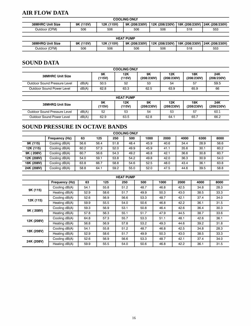
AIR FLOW DATACOOLING ONLY
38MHRC Unit Size 9K (115V) 12K (115V) 9K (208/230V) 12K (208/230V) 18K (208/230V) 24K (208/230V)
Outdoor (CFM) 506 506 506 506 518 553
HEAT PUMP
38MHRQ Unit Size 9K (115V) 12K (115V) 9K (208/230V) 12K (208/230V) 18K (208/230V) 24K (208/230V)
Outdoor (CFM) 506 506 506 506 518 553
SOUND DATACOOLING ONLY
38MHRC Unit Size9K
(115V)12K
(115V)9K
(208/230V)12K
(208/230V)18K
(208/230V)24K
(208/230V)
Outdoor Sound Pressure Level dB(A) 50.5 52 53 54 57 59.5
Outdoor Sound Power Level dB(A) 62.8 63.3 62.5 63.9 65.9 66
HEAT PUMP
38MHRQ Unit Size9K
(115V)12K
(115V)9K
(208/230V)12K
(208/230V)18K
(208/230V)24K
(208/230V)
Outdoor Sound Pressure Level dB(A) 52 53 54 53 57 60.1
Outdoor Sound Power Level dB(A) 62.9 63.5 62.8 64.1 65.7 66.2
SOUND PRESSURE IN OCTAVE BANDSCOOLING ONLY
Frequency (Hz) 63 125 250 500 1000 2000 4000 6300 8000
9K (115) Cooling dB(A) 56.6 56.4 51.8 48.4 45.9 40.6 34.4 28.9 56.6
12K (115) Cooling dB(A) 60.2 57.3 52.0 49.9 45.9 41.1 35.6 30.1 60.2
9K ( 208V) Cooling dB(A) 60.7 56.6 54.3 49.2 46.8 42.1 36.6 30.8 60.7
12K (208V) Cooling dB(A) 54.0 59.1 53.8 54.2 49.8 42.0 36.3 30.9 54.0
18K (208V) Cooling dB(A) 63.8 66.7 58.8 54.6 52.5 48.0 43.4 36.1 63.8
24K (208V) Cooling dB(A) 58.8 64.1 59.2 55.0 52.0 47.5 44.6 39.5 58.8
HEAT PUMP
Frequency (Hz) 63 125 250 500 1000 2000 4000 8000
9K (115)Cooling dB(A) 54.1 55.8 51.2 48.7 46.8 42.5 34.8 28.3
Heating dB(A) 52.9 58.6 51.7 49.9 50.3 43.0 38.5 33.3
12K (115)Cooling dB(A) 52.6 56.9 56.6 53.3 48.7 42.1 37.4 34.0
Heating dB(A) 59.9 55.5 54.0 50.6 46.8 42.2 36.1 31.5
9K ( 208V)Cooling dB(A) 59.3 56.9 53.1 50.8 46.4 42.6 36.4 30.3
Heating dB(A) 57.8 56.3 55.1 51.7 47.9 44.5 38.7 33.6
12K (208V)Cooling dB(A) 64.8 57.3 55.7 53.3 51.1 48.1 42.6 36.1
Heating dB(A) 56.8 56.9 57.8 53.2 49.3 44.6 39.2 31.8
18K (208V)Cooling dB(A) 54.1 55.8 51.2 48.7 46.8 42.5 34.8 28.3
Heating dB(A) 52.9 58.6 51.7 49.9 50.3 43.0 38.5 33.3
24K (208V)Cooling dB(A) 52.6 56.9 56.6 53.3 48.7 42.1 37.4 34.0
Heating dB(A) 59.9 55.5 54.0 50.6 46.8 42.2 36.1 31.5

17
OUTDOOR UNIT SOUND PRESSURE TEST CONDITIONS
NOTE: H=0.5 x Height of outdoor unit
INDOOR CONDITION OUTDOOR CONDITION
DB WB DB WB
Cooling 80.6F (27C) 66.2F (19C) 95F (35C) 75.2F (24C)
Heating 68F (20C) 59F (15C) 44.6F (7C) 42.8F (6C)
ELECTRICAL DATA
Cooling Only
Outdoor Unit Size 9K 12K 9K 12K 18K 24K
Volts-PH-Hz (115V) (115V) (208/230V) (208/230V) (208/230V) (208/230V)
Max – Min*Oper. Voltage
127-104 127-104 253-187 253-187 253-187 253-187
Power SupplyMCA 13 13 7 7 11 16
MOCP 20 20 15 15 15 25
Compressor RLA 9 9.5 4.5 4.5 7 11
Outdoor Fan Motor
FLA 0.6 0.6 0.4 0.4 0.5 0.6
Rated HP 0.054 0.054 0.054 0.054 0.065 0.068
Output 40 40 40 40 48 45
Heat Pump
Outdoor Unit Size 9K 12K 9K 12K 18K 24K
Volts-PH-Hz (115V) (115V) (208/230V) (208/230V) (208/230V) (208/230V)
Max – Min*Oper. Voltage
127-104 127-104 253-187 253-187 253-187 253-187
Power SupplyMCA 13 13 8 10 15 18
MOCP 20 20 15 15 20 25
Compressor RLA 9 9.5 5.5 6.8 10.5 12
Outdoor Fan Motor
FLA 0.7 0.7 0.4 0.4 0.6 0.6
Rated HP 0.043 0.043 0.043 0.043 0.065 0.085
Output 32 32 32 32 48 63
*Permissible limits of the voltage range at which the unit will operate satisfactorily.
LEGEND
FLA - Full Load Amps
MCA - Minimum Circuit Amps
RLA - Rated Load Amps

18
WIRING DIAGRAMS
COMPRESSOR
Y/G
4-WAY
CN 50DC-FAN
OPTIONAL:DC-FAN
CN 7
3
AC-FA
N
OPTIONAL: AC-FAN
5CN 25CN 60
OPTIONAL
CRANKCASE HEATER
CN 17
OPTIONAL
LB
EU
BROWN
YELLOW OR BLACK
SN N
DE
R LB
EU
Y/GL
Y/G
AMBIENT TEMP. SENSOR
DISCHARGE TEMP. SENSOR
CN 21
CONDENSER TEMP . SENSOR
Y/G
CN 1A
Y/G
Y/G
3
CN4_
1CN
4_2
CN4_
3
CN4_
4
REACTOR
CAPACI
TOR
BROW
N(BL
ACK)
BROW
N(BL
ACK)
BLACK
(BROW
N)
BLACK
(BROW
N)
Y/G
22
BLACK
WV
REDBLUE
U5
GRAYBLACK
GRAY3
BLACK2
BROWN1
BROWN
OP
TIO
NA
LTNI
OJ T
SA
F
NOTE: The connection wires for thereactor and the capacitor should bethe same color; either black or brown.
Notes:This symbol indicates the elementis optional, the actual shape shallprevail.
16022000B23477
Input: 115V high voltage connector withL/N/signal/groundOutput: 0~320VDC to control DC FANOutput:115VAC High voltage connector forpower factor corrector(PFC)
Input: temperature acquisition (0~5VDC)
Output: 0~115 VAC to control AC FANConnector for electronic expansion valve(0-12VDC)
Output: 115 VAC to control 4-way valveOutput: 115VAC to control crankcase heater
Fig. 5 – Wiring Diagram Sizes 09K−12K (115V)

19
WIRING DIAGRAMS (CONTINUED)
4-WAY
DC-FANOPTIONAL:DC-FAN
CN 7
3
CN 60OPTIONAL
CRANKCASE HEATER
CN 17OPTIONAL
BLUE
BROWN
YELLOW OR BLACK
INDOOR UNIT
SL2 L2
POWER SUPPLY
RED
BLUE OR BLACK
Y/GL1
Y/G
AMBIENT TEMP. SENSOR
DISCHARGE TEMP. SENSOR
CN 21
CONDENSER TEMP. SENSOR
Y/G
CN 1A
Y/G
Y/G
COMPRESSOR
Y/GCN 503
U V W
BLUE
RED
BLACK
AC-FANCAPACITOR
OPTIO
NAL: AC-FAN
5
3Y/G
Notes:This symbol indicates the element is optional, the actual shape shallprevail.
CN 32CN 9
REACTOR 1005AL
OPTIONAL
BLUE
BLUE
MAIN BOARD
CN 25
RED
BLUE
~
Input: 220V high voltage connector withL/N/signal/groundOutput: 0~320V DC to connect DC FAN
To connect PFC reactor
Input: temperature sensor connector (0~5V DC)
Output: 0~220V AC to connect AC FAN
Output: 0~320V AC to connect compressor
Output: 0~220V AC to connect 4-way valveOutput: 220V AC to connect crankcase heater
Fig. 6 – Wiring Diagram − Sizes 09K, 12K (230V)

20
WIRING DIAGRAMS (CONTINUED)
123
UVW
CN60
COMPRESSOR
Y/G
REDBLUE
BLACK
OUTDOORMAINPCB
BLUE
BLACKRED
CN13CN12
W-4AY
REACTOR
BLUE
BLUE
UVW
Y/G
RED
L1 L2 S L1 L2
BLACK(BLUE)
L1 L2
OPTIONAL
CN16
OPTIONAL:the electric heating belt of compressor
HEATER 1
OUTDOOR WIRING DIAGRAM
OUT DOOR DC FAN
CN414
3
OUT DOOR AC FAN
F NA PAC
TI CARO
BROWNBLUE
CN5
Applicable to the units adopting DC motor only
Applicable to the units adopting AC motor only
Y/G
CN30
CN10CN1
CONDENSER TEMPERATURE SENSOR
OUTDOOR AMBIENTTEMPERATURE SENSOR
WHITE
BLAC
K
DISCHARGE SENSOR
KCALB
DER
CN17
(RED
)
BLACK
(BLACK)CN2
CN7CN8
Y/G
CN6-1
NWORB
BLUE
YELLOW
CN3
Input: 230V high voltage connector withL1/L2/signal/ground
Output: 0~320VDC to control DC FAN
Output: PWM for UVW to control Compressor(0~320VAC) Output: 220V AC to control crankcase heater
Output: 0~220V AC to control 4-way valveInput: Temperature acquisition(0-5VDC)
Output: 0~220VAC to control AC FAN
CN12/CN13 Output: Connection of the high voltage (REACTOR)
Fig. 7 – Wiring Diagram Sizes 18K − 24K (Heat Pump Units)

21
WIRING DIAGRAMS (CONTINUED)
4-WAY
DC-FANOPTIONAL:DC-FAN
CN 414
3
CN 60
OPTIONAL
CRANKCASE HEATER
CN 16
OPTIONAL
AMBIENT TEMP. SENSOR
DISCHARGE TEMP. SENSOR
CN 17
CONDENSER TEMP. SENSORY/G
OUTDOORMAINPCB
BLUE
BROWN
BLACK
SL2 L1 L2
RED
BLUE
L1Y/G
Y/G
CN 3
Y/G
Y/G
Y/G
OPTIONAL
CAPACITOR
OPTIONAL: AC-FAN
5
3
CN 5
Y/G
L1 L2
Notes:This symbol indicatesthe element is optional,the actual shape shallprevail.
S
Yellow
Red
Blue
According to the real objects
16022000B23636
COMPRESSOR
BLUE
BLACK
CN 21
CN 29CN 28CN 27
BLUERED
BLACK
WVU
Input: 220V high voltage connector withL1/L2/signal/ground
Output: 0~320VDC to control DC FAN
Output: PWM for UVW to control Compressor(0~320VAC) Output: 220V AC to control crankcase heater
Output: 0~220V AC to control 4-way valveInput: Temperature acquisition(0-5VDC)
RED
Output: 0~220VAC to control AC FAN
Fig. 8 – Wiring Diagram Sizes 18K − 24K (Cooling Only Units)

22
GUIDE SPECIFICATIONSHORIZONTAL DISCHARGE OUTDOOR UNITS
Size Range: 3/4 to 2 Ton Nominal Cooling and Heating CapacityModel Number: 38MHR
PART 1 − GENERAL1.01 System DescriptionA. Outdoor air−cooled split system compressor sections suitable
for on−the−ground, rooftop, wall hung or balcony mounting.Units consist of a rotary compressor, an air−cooled coil,propeller−type draw−through outdoor fan, reversing valve(HP), accumulator (HP units), metering device(s), and a controlbox. Units discharge air horizontally as shown on the contractdrawings. Units function as the outdoor component of anair−to−air cooling only, or heat pump system.
B. Units are to be used in a refrigeration circuit matched toductless heat pump fan coil units.
1.02 Agency ListingsA. Unit construction complies with ANSI/ASHRAE 15, latest
revision, and with the NEC.B. Units are evaluated in accordance with UL standard 1995.
C. Units are listed in the CEC directory.
D. Unit cabinet is capable of withstanding 500−hour salt spray testper Federal Test Standard No. 141 (method 6061).
E. Air−cooled condenser coils are leak tested at 550 psig.
1.03 Delivery, Storage, And HandlingUnits are shipped in one piece and are stored and handled per unitmanufacturer’s recommendations.
1.04 Warranty (For Inclusion By Specifying Engineer)
PART 2 − PRODUCTS2.01 EquipmentA. General:Factory assembled, single piece, air−cooled outdoor unit.Contained within the unit enclosure is all the factory wiring,piping, controls, and the compressor.B. Unit Cabinet:
1. Unit cabinet is constructed of galvanized steel, bonderizedand coated with a baked−enamel finish on the inside andoutside (PANTONE 7527U).
2. Unit access panels is removable with minimal screws andprovides full access to the compressor, fan, and controlcomponents.
3. The outdoor compartment is isolated and has an acousticlining to assure quiet operation.
C. Fans:1. Outdoor fans are the direct drive propeller type, and
discharges air horizontally. Fans draw air through theoutdoor coil.
2. Outdoor fan motors are totally enclosed, single phase motorswith class E insulation and permanently lubricated ballbearings. Motor shall be protected by internal thermal overloadprotection.
3. The shaft has inherent corrosion resistance.4. Fan blades are non−metallic and statically and dynamically
balanced.
5. Outdoor fan openings are equipped with a PVC metal/meshcoated protection grille over the fan.
D. Compressor:1. Compressor is the fully hermetic rotary type.2. Compressor is equipped with an oil system, operating oil
charge, and a motor.
3. Motor is NEMA rated class E, suitable for operation in arefrigerant atmosphere.
4. Compressor assembly is installed on rubber vibrationisolators.
E. Outdoor Coil:The coil is constructed of aluminum blue hydrophilic pre−coatedfins mechanically bonded to seamless copper tubes, which arecleaned, dehydrated, and sealed.F. Refrigeration Components:Refrigerant circuit components include a brass external liquid lineservice valve with service gage port connections, a suction lineservice valve with a service gage connection port, service gage portconnections on compressor suction and discharge lines with Schradertype fittings with brass caps, accumulator, reversing valve.G. Controls and Safeties:Operating controls and safeties are factory selected, assembled, andtested. The minimum control functions include the following:
1. Controls:a. A time delay control sequence is provided standard through
the fan coil board
b. Automatic outdoor fan motor protection.2. Safeties:
a. System diagnosticsb. Compressor motor current and temperature overload
protection
c. Outdoor fan failure protection.H. Electrical Requirements:
1. Unit operates on single−phase, 60 Hz power at 115V forunit sizes 09−12 and 208/230V for unit sizes 09, 12, 18,and 24 as specified.
2. Unit electrical power has a single point connection.
3. Unit Control voltage to the indoor fan coil is 0−15V DC.
4. All power and control wiring must be installed per NECand all local electrical codes.
5. The unit has high and low voltage terminal blockconnections.

23

24
Copyright 2017 Carrier Corporation � 7310 W. Morris St. � Indianapolis, IN 46231 Edition Date: 06/17
Manufacturer reserves the right to change, at any time, specifications and designs without notice and without obligations.
Catalog No: 38MHR-02PD
Replaces: 38MHR-01PD


