
2008-01-0198
Project Orion, Environmental Control and Life Support System Integrated Studies
James F. Russell Lockheed Martin
John F. Lewis NASA, Johnson Space Center
Copyright © 2008 SAE International
ABSTRACT
Orion is the next vehicle for human space travel. Humans will be sustained in space by the Orion subystem, environmental control and life support (ECLS). The ECLS concept at the subsystem level is outlined by function and technology. In the past two years, the interface definition with other subsystems has increased through different integrated studies. The paper presents the key requirements and discusses three recent studies (e.g., unpressurized cargo) along with the respective impacts on the ECLS design moving forward.
INTRODUCTION
Project Orion is a joint effort between National Aeronautics and Space Administration (NASA), Lockheed Martin and Teammates to produce the next generation of human spacecraft for the United States. A human in that spacecraft is sustained by the Environmental Control and Life Support (ECLS) subsystem. The ECLS design team is Lockheed Martin, Hamilton Sundstrand and Paragon Space Development Corporation.
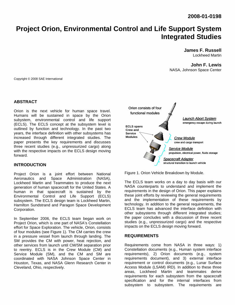
In September 2006, the ECLS team began work on Project Orion, which is one part of NASA’s Constellation effort for Space Exploration. The vehicle, Orion, consists of four modules (see Figure 1). The CM carries the crew in a pressure vessel from launch through landing. The SM provides the CM with power, heat rejection, and other services from launch until CM/SM separation prior to reentry. ECLS is in the Crew Module (CM) and Service Module (SM), and the CM and SM are coordinated with NASA Johnson Space Center in Houston, Texas, and NASA Glenn Research Center in Cleveland, Ohio, respectively.
Spacecraft Adapterstructural transition to launch vehicle
Orion consists of four
functional modules
Launch Abort Systememergency escape during launch
Crew Modulecrew and cargo transport
Service Modulepropulsion, electrical power, fluids storage
Spacecraft Adapterstructural transition to launch vehicle
Orion consists of four
functional modules
Launch Abort Systememergency escape during launch
Crew Modulecrew and cargo transport
Service Modulepropulsion, electrical power, fluids storage
ECLS spans Crew and Service Modules
Figure 1. Orion Vehicle Breakdown by Module.
The ECLS team works on a day to day basis with our NASA counterparts to understand and implement the requirements in the design of Orion. This paper explains these joint efforts by reviewing the general requirements and the implementation of these requirements by technology. In addition to the general requirements, the ECLS team has advanced the interface definition with other subsystems through different integrated studies; the paper concludes with a discussion of three recent studies (e.g., unpressurized cargo) and the respective impacts on the ECLS design moving forward.
REQUIREMENTS
Requirements come from NASA in three ways: 1) Constellation documents (e.g., Human system interface requirements), 2) Orion documents (e.g., system requirements document), and 3) external interface requirement or control documents (e.g., Lunar Surface Access Module (LSAM) IRD). In addition to these three areas, Lockheed Martin and teammates derive requirements for each subsystem from the spacecraft specification and for the internal interfaces from subsystem to subsystem. The requirements are
allocated by ECLS into the following seven functional categories.
1. Active Thermal Control System (ATCS)
2. Air Revitalization System (ARS)
3. Fire Detection and Suppresion (FDS)
4. Flight Suit Interface (FSI)
5. Potable Water (PWMS)
6. Pressure control system (PCS)
7. Waste Management (WM)
These seven functional categories are similar to those used on the International Space Station (see Table 3 of [1]). The specific requirements are addressed by functional category and technology in the companion paper for Orion ECLS [2].
For the purposes of this paper, the key requirements are for Orion to:
1. Support zero to six crew for a mission to the International Space Station (ISS) and zero to four crew for a Lunar mission,
2. Support the crew for the crewed duration of an ISS and a Lunar mission,
3. Provide a nominal shirt sleeve environment for the crew,
4. Operate for six months in a quiescent mode attached to ISS or in Low Lunar Orbit,
5. Provide for unpressurized cargo on ISS and Lunar missions,
6. Provide thermal control of avionics, batteries, and crew,
7. Design for two fault tolerance, and 8. Stay equal to or less than the mass, power, and
volume allocations for ECLS. With support from NASA, the Constellation and Orion requirements were understood, and this understanding was communicated at the Systems Requirement Review in 2007 with the initial delivery of the ECLS Subsystem Design and Data Handbook.
TECHNOLOGIES
The Orion requirements envelope a technology trade space. The ECLS design team’s goal is to meet or exceed the requirements within the limits of schedule and cost. To accomplish this task, the ECLS design team uses past experience and lessons learned from the design and operation of ECLS on Apollo, Space Shuttle, and ISS.
When considering the operation of past and future space vehicles, technologies fall into broader categories than
the seven functional categories (see Table 1). The categories of air, water, food, and thermal control represent the essentials to support human life. Waste management and fire safety are needed to maintain a safe environment. Technologies also rely on vehicle and environmental interfaces to meet requirements or to provide a lower mass solution for those environments, such as the vacuum resource on ISS.
Table 1. Orion Technologies by ECLS Category
Category Function Technology
Air Atmosphere revitalization.
Pressure control
Solid amine bed and activated carbon filter
O2 and N2 tanks with total pressure and oxygen sensors
Fire Safety Fire prevention
Fire detection and suppression
Fire protection
-
Smoke detectors and a Halon system
Handheld extinguisher
Food Food provision Prepackaged food (by Crew Subsystem)
Thermal Control
Active thermal control
Passive thermal control
Heat exchangers, cold plates, radiator, sublimator, R134a evaporator, and phase change material (PCM)
Heaters, coatings, and insulation (by Passive Thermal Control Subsystem)
Waste Waste management
Toilet with fecal collection and urine venting
Water Water management
Water tank with rubber bladders
Category Function Technology
Interfaces Vacuum services from external environment
Structure with minimal leakage
Flight Suits (EVA)
Sublimator, urine, and solid amine bed vents
Pressure sensor .
Atmospheric control and suit cooling
In Table 1, the general categories are linked to the Orion technologies from the seven functional categories. For example, ARS and PCS are in the Air category, and Flight Suit Interface is in the Interfaces category. The baseline technologies for Orion are described in the following list and shown in Figures 2 and 3, which show the CM and SM, respectively.
ARS – A pressure swing assembly with solid amine adsorbs water and carbon dioxide (Eckart 184 / 08ICES-0075) from the crew in the cabin or flight suits and desorbs the bed through a vent. A activated carbon filter with acid impregnation provides trace contaminant control, and a sensor monitors the trace contaminants in the carbin or flight suits. Forced convection through a non-condensing heat exchanger cools the cabin air, and cabin heating is provided by the metabolic heat from the crew.
PCS – Oxygen and nitrogen are stored in Composite Overwrap Pressure Vessels (COPV). The release of nitrogen or oxygen from the tanks is regulated by total and oxygen pressure sensors. In case of a PCS failure, positive and negative relief valves are used to protect the integrity of the pressurve vessel from over or underpressurization, respectively.
FDS – Automated or manual system disperses halon to extinguish fires. A handheld fire extinguisher provides supplemental fire protection. The material used in ECLS technologies is also selected to prevent ignition and fire propogation to the extent possible.
ATCS – Propylene glycol with water is actively pumped through the CM and SM to remove heat from heat exchangers. Heat is stored by phase change material (PCM) or rejected by a body mounted radiator, water sublimator, or R134a evaporator.
WM – A toilet captures and stores fecal matter, while urine is vented overboard (when allowed).
PW – Rubber bladder tanks store water for drinking, washing, or sublimating. A point of use filter provides further water conditioning prior to use by the crew.
FSI – When the crew is in flight suits, an umbilical interface panel links the flight suit to the ARS, PCS, and ATCS to revitalize the air and cool the crew.
WMS
ECLSS BayAvionics Cold Plates
Avionics Cold Plates
Crew Console Cold Plate
Operator Umbilical connection
Operator Umbilical connection
Water Dispenser &
Galley
IVA Umbilical Connections
WMS
ECLSS BayAvionics Cold Plates
Avionics Cold Plates
Crew Console Cold Plate
Operator Umbilical connection
Operator Umbilical connection
Water Dispenser &
Galley
IVA Umbilical Connections
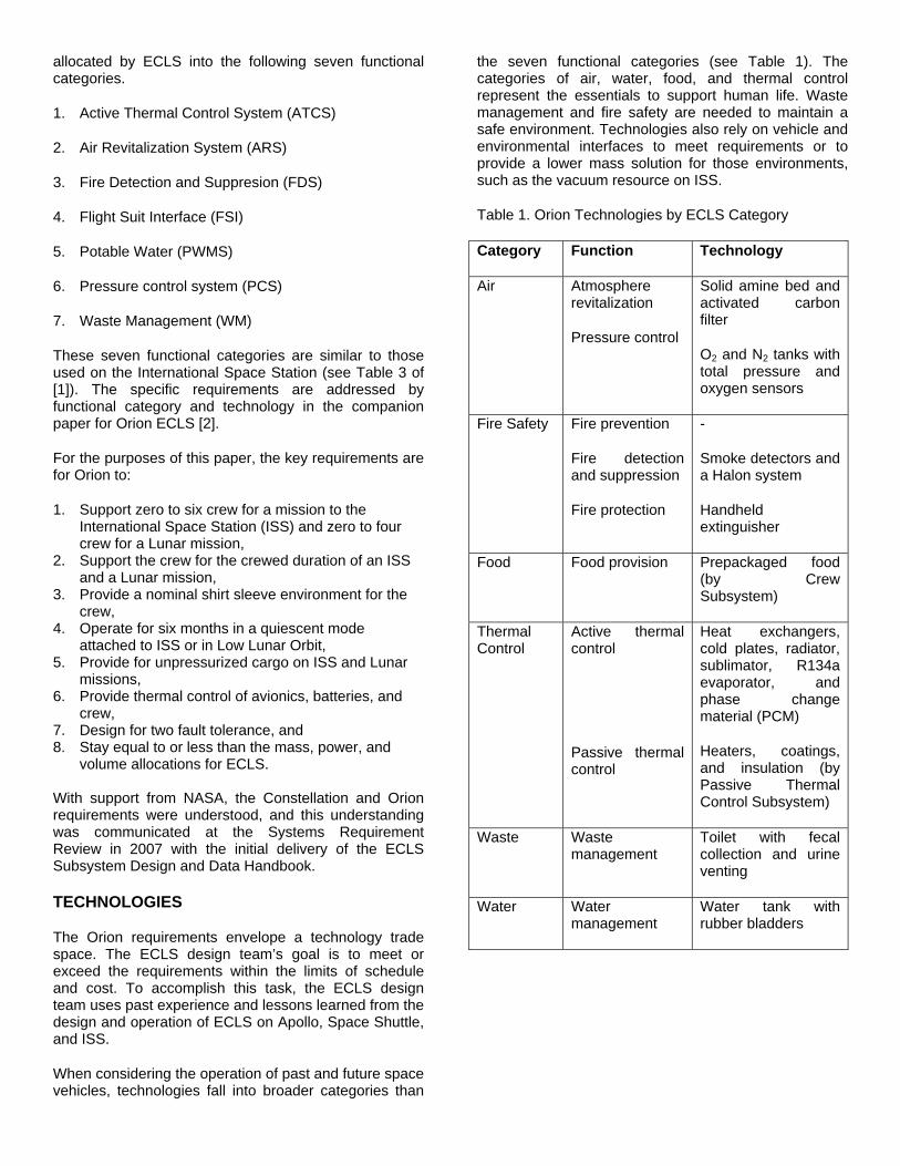
Figure 2. ECLS Technologies in Crew Module.
Lunar Science Payload
Oxygen, Nitrogen, Water, and ATCS lines through CM/SM umbilical
High Gain Antenna
Radiators
Ultra-flex Solar Array
Oxygen, nitrogen, and water tanks inside the SM
Lunar Science Payload
Oxygen, Nitrogen, Water, and ATCS lines through CM/SM umbilical
High Gain Antenna
Radiators
Ultra-flex Solar Array
Oxygen, nitrogen, and water tanks inside the SM
Figure 3. ECLS Technologies in Service Module.
As shown in Figure 2, most of the ECLS technologies are in the CM and are located in an ECLS bay or cabin. The oxygen, nitrogen and water commodities are stored in the SM (see Figure 3), and the radiator are body mounted to the SM. Overall, these technologies represent the ECLS team’s low mass solution to meet requirements within the limits of cost and schedule.
INTEGRATION STUDIES
The baseline requirements define the general functionality and in turn the technologies for the vehicle. Integrating ECLS technologies into the vehicle requires deriving additional requirements and modifying the baseline design accordingly. In 2006 to 2007, the ECLS team refined the vehicle and ECLS interfaces in three studies:
1. An assessment of ATCS and integrated vehicle performance in low lunar orbit with respect to attitude.
2. A study of power and thermal performance in Earth-Lunar transit, and
3. An unpressurized cargo study, which modified the ECLS to structures interface to enable a new cargo configuration for ISS missions.
The following section provides more details about each study.
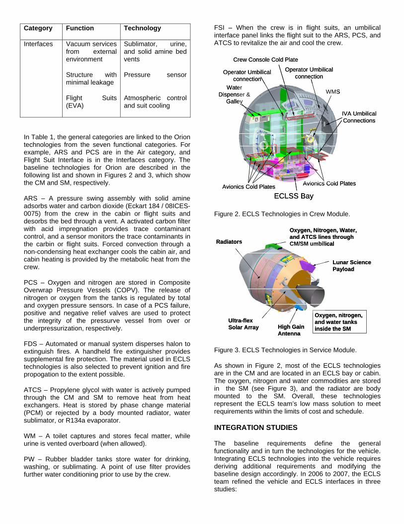
LUNAR STUDY OF ATCS PERFORMANCE - In Low Lunar Orbit (LLO), ATCS uses a body mounted radiator and a phase change material heat exchanger (PCM HX) to maintain thermal control [3]. When the effective sink temperature for the radiator exceeds the radiator operating temperature at the subsolar point, the outlet coolant temperature from the radiator exceeds the ATCS set point, so the radiator alone is unable to meet performance requirements (see Figure 4). During this period, a PCM HX lowers the coolant temperature by melting the PCM to store the heat. The operational period and mass of the PCM HX is based on the ATCS set point, radiator properties, and the sink temperature in LLO.
Lunar Orbital Period
ATCS Set Point
Tem
pera
ture
Baseline
Tighter attitude control
Lunar Orbital Period
ATCS Set Point
Tem
pera
ture
Baseline
Tighter attitude control
ATCS Set Point
Tem
pera
ture
Baseline
Tighter attitude control
Figure 4. Radiator outlet temperature in LLO for the baseline attitude (solid line) and tighter attitude (dotted line). The baseline requires PCM to maintain the ATCS set point (hatched and shaded portion). With a tighter attitude, ATCS requires less PCM (shaded) to perform the same function.
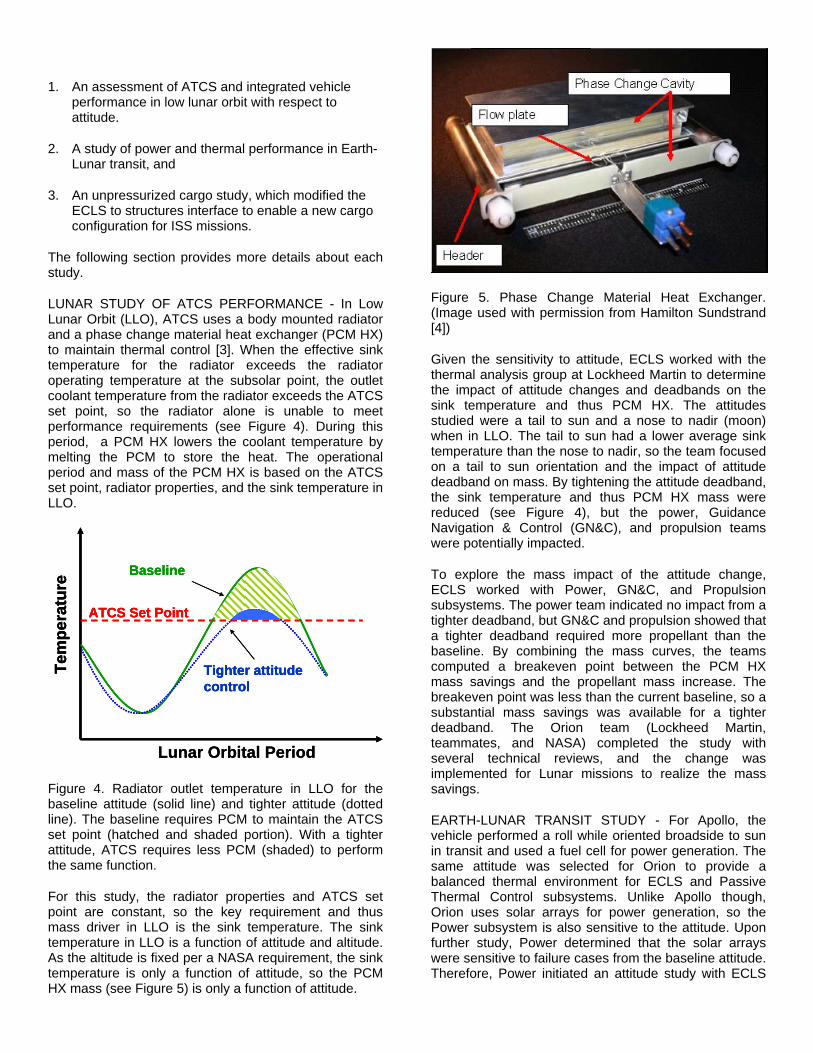
For this study, the radiator properties and ATCS set point are constant, so the key requirement and thus mass driver in LLO is the sink temperature. The sink temperature in LLO is a function of attitude and altitude. As the altitude is fixed per a NASA requirement, the sink temperature is only a function of attitude, so the PCM HX mass (see Figure 5) is only a function of attitude.
Figure 5. Phase Change Material Heat Exchanger. (Image used with permission from Hamilton Sundstrand [4])
Given the sensitivity to attitude, ECLS worked with the thermal analysis group at Lockheed Martin to determine the impact of attitude changes and deadbands on the sink temperature and thus PCM HX. The attitudes studied were a tail to sun and a nose to nadir (moon) when in LLO. The tail to sun had a lower average sink temperature than the nose to nadir, so the team focused on a tail to sun orientation and the impact of attitude deadband on mass. By tightening the attitude deadband, the sink temperature and thus PCM HX mass were reduced (see Figure 4), but the power, Guidance Navigation & Control (GN&C), and propulsion teams were potentially impacted.
To explore the mass impact of the attitude change, ECLS worked with Power, GN&C, and Propulsion subsystems. The power team indicated no impact from a tighter deadband, but GN&C and propulsion showed that a tighter deadband required more propellant than the baseline. By combining the mass curves, the teams computed a breakeven point between the PCM HX mass savings and the propellant mass increase. The breakeven point was less than the current baseline, so a substantial mass savings was available for a tighter deadband. The Orion team (Lockheed Martin, teammates, and NASA) completed the study with several technical reviews, and the change was implemented for Lunar missions to realize the mass savings.
EARTH-LUNAR TRANSIT STUDY - For Apollo, the vehicle performed a roll while oriented broadside to sun in transit and used a fuel cell for power generation. The same attitude was selected for Orion to provide a balanced thermal environment for ECLS and Passive Thermal Control subsystems. Unlike Apollo though, Orion uses solar arrays for power generation, so the Power subsystem is also sensitive to the attitude. Upon further study, Power determined that the solar arrays were sensitive to failure cases from the baseline attitude. Therefore, Power initiated an attitude study with ECLS

and PTC to study the impact of alternate attitudes on performance.
The requirements for this study are given for the ECLS, Power, and PTC subsystems, where PTC also addresses the material limits of other subsystems and LSAM. ECLS requires a view of a cold sink temperature (e.g. deep space) by the radiator to reject heat but not too much to freeze the coolant in the body mounted radiator. Passive thermal control require coatings and/or heat (heaters or solar heaters) to stay within minimum and maximum material limits; e.g. above freezing for water or below upper limit of cryogenic tanks on LSAM. Power requires the solar arrays to be at or near perpendicular to the plane of the sun for power generation.
Two attitudes under consideration are broadside to sun with a roll and tail to sun. For the baseline attitude, the solar arrays are not always pointed to the sun, so the solar arrays are less effective. Given the high power requirements in transit for LSAM, this could be a driving case. To increase power performance, a steady state attitude for Orion of tail to sun without a roll would increase solar array effectiveness. In a tail to sun orientation, the LSAM is shaded from the sun by Orion, which meets the requirement for a cold environment for the cryogenic tanks. However, the LSAM cabin, CM and SM are exposed to the deep space environment for the transit lasting multiple days. Given the long duration of the exposure, the modules would reach a cold steady state below acceptable material limits without heaters. Heaters require a significant amount of additional power to meet initial material limits and further drive solar array size. From the initial round of analysis, both attitudes have issues, but tail to sun appears to be more favorable to meet Constellation requirements for Orion and LSAM.
Going forward, PTC and Power will continue to study the relationship between material limit, heaters and solar array size. The study will examine other attitudes and approaches to meet the minimum material limits.
UNPRESSURIZED CARGO STUDY - For ISS missions, the volume for unpressurized cargo is larger than for Lunar missions. On Lunar missions, the cargo will be placed on the outside of the SM. Given the size and new access requirements for ISS cargo, the vehicle is examining new options to modify the SM interface with cargo.
The primary option (and new derived requirement) is to place the unpressurized cargo within the SM for ISS missions. To enable this option, ECLS, Structures and Mechanism subsystems are considering two options for cargo deployment: a static opening or a door (see Figure 6).
Figure 6. Door concept for Unpressurized Cargo
ECLS evaluated impact of a static cargo opening and a door mechanism on the ability to meet the key requirements of heat rejection and mass. For ISS missions with current heat loads and margins, nearly all of the SM area is needed for heat rejection. By using a door concept, the door could have integral radiators to meet thermal performance requirements. For the static opening, radiator area is lost, so additional water for water sublimation could be used as a possible solution to maintain thermal balance for ISS missions.
On a vehicle level, ECLS, Structures and Mechanisms are all impacted. A static opening saves mass by removing radiator but adds sublimator water; aeroheating during launch of the cargo and SM would need to be addressed. A door provides protection from aeroheating and the required radiator area, but the door adds mass for the Mechanism, supporting Structure and radiator interface as well as new failure mode to the vehicle.
For both options, the design would benefit by reducing the radiator area to three-quarters of the available area. Radiator area is dependent on the driving case heat load, so ECLS is working with the Power subsystem to reduce heat load for the driving case and is reexamining the assumptions for radiator performance. Going forward, ECLS is focusing on reducing radiator area to enable the unpressurized cargo option with no mass increase.
CONCLUSION
In September 2006, LM and teammates began work on Project Orion with NASA. In early 2007, the ECLS team successfully completed system requirements review. Since the review, the ECLS design team has further increased vehicle and subsystem fidelity to meet the interface requirements for other Constellation elements. These efforts included a refinement of the external IRD/ICDs to Ground Operations, Extravehicular Activities (EVA), Unpressurized Cargo, International Space Station (ISS), and LSAM (Altair). In the course of these interface studies, ECLS realized mass savings for
the Lunar mission and worked to enable a new definition of unpressurized cargo for ISS missions. In the coming months, the ECLS design team is working towards preliminary design review (PDR) in 2008.
ACKNOWLEDGMENTS
The work presented here has been supported by the National Aeronautics and Space Administration, NASA, through Project Orion, (Contract # NNJ06TA25C). Thank you to Gary Adamson from Hamilton Sundstrand for obtaining permission to use the image in Figure 5.
REFERENCES
1. Russell, J.F., D.M. Klaus, " Maintenance, reliability and policies for orbital space station life support systems," Reliability Engineering and System Safety, 92: 6 and pg. 808-820, Elsevier 0951-8320, Orlando, FL, 2007.
2. Scull, T.D., G.M. Young. "Status of the Orion Environmental Control and Life Support Architecture," 08ICES-0202, SAE, Warrendale, PA, 2008.
3. Lewis, J.F., R. Barido, C. Cross, L. Peterson, G. Tuan, and R. Carrasquillo. “Crew Exploration Vehicle Environmental Control and Life Support Development Status,” 2007-01-3044, SAE, Warrendale, PA, 2007.
4. Adamson, G., M. Caron. “Thermal Control System for Crew Space Vehicles,” Abstract STAIF, American Institute of Physics, Secaucus, NJ, 2007.
CONTACT
James F. Russell, PhD. [email protected]
ADDITIONAL SOURCES
Images in Figures 1, 2, 3 and 6 are from the following public outreach presentation: McKenzie, P. “Project Orion Public Outreach Overview,” Lockheed Martin, Denver, CO, 2007.
DEFINITIONS, ACRONYMS, ABBREVIATIONS
ARS Air Revitalization System
ATCS Active Thermal Control System
ECLS Environmental Control and Life Support
EVA Extravehicular Activity
FDS Fire Detection and Suppresion
FSI Flight Suit Interface
GN&C Guidance Navigation and Control
HX heat exchanger
ICD Interface Control Document
IRD Interface Requirement Definition
ISS International Space Station
kW kilowatt of electrical power
kWth kilowatt of thermal energy
LSAM Lunar Surface Access Module (Altair)
PCM phase change material
PCS Pressure control system
PTC Passive Thermal Control
PWMS Potable Water Management System
WM Waste Management
Copyright © 2010 Boeing. All rights reserved.
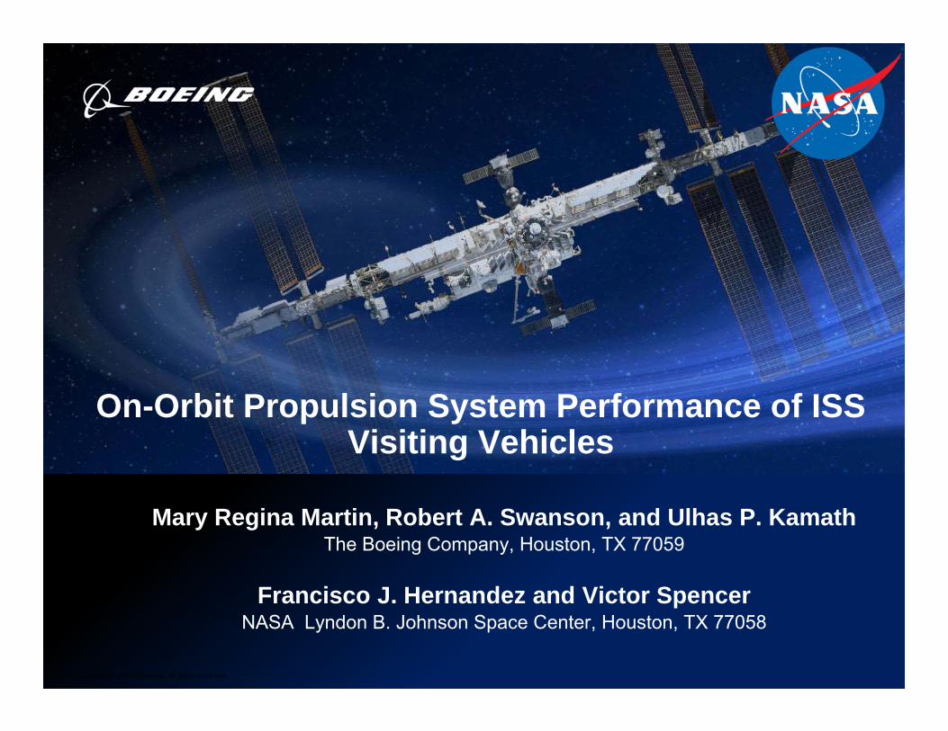
On-Orbit Propulsion System Performance of ISS Visiting Vehicles
Mary Regina Martin, Robert A. Swanson, and Ulhas P. KamathThe Boeing Company, Houston, TX 77059
Francisco J. Hernandez and Victor SpencerNASA Lyndon B. Johnson Space Center, Houston, TX 77058

Overview
2
• Abstract• ISS Visiting Vehicles• Propulsion System Requirements and Priorities• Hazard Control• Design Drivers for Pressure Systems• Integration and Operations• Conclusion• Sources

3
Abstract• ISS represents the culmination of over two decades of unprecedented
global human endeavors to conceive, design, build and operate aresearch laboratory in space.
• Uninterrupted human presence in space has been made possible byan international fleet of space vehicles facilitating crew rotation,delivery of science experiments and replenishment of propellantsand supplies.
• On-orbit propulsion systems on both ISS and Visiting Vehicles areessential to the continuous operation of the ISS.
• This paper compares the ISS visiting vehicle propulsion systems byproviding an overview of key design drivers, operational considerationsand performance characteristics.
• Despite their differences in design, functionality, and purpose, all visitingvehicles must adhere to a common set of interface requirements along withsafety and operational requirements.
• This paper addresses a wide variety of methods for satisfying theserequirements and mitigating credible hazards anticipated during the on-orbitlife of propulsion systems, as well as the seamless integration necessary forthe continued operation of the ISS.
4
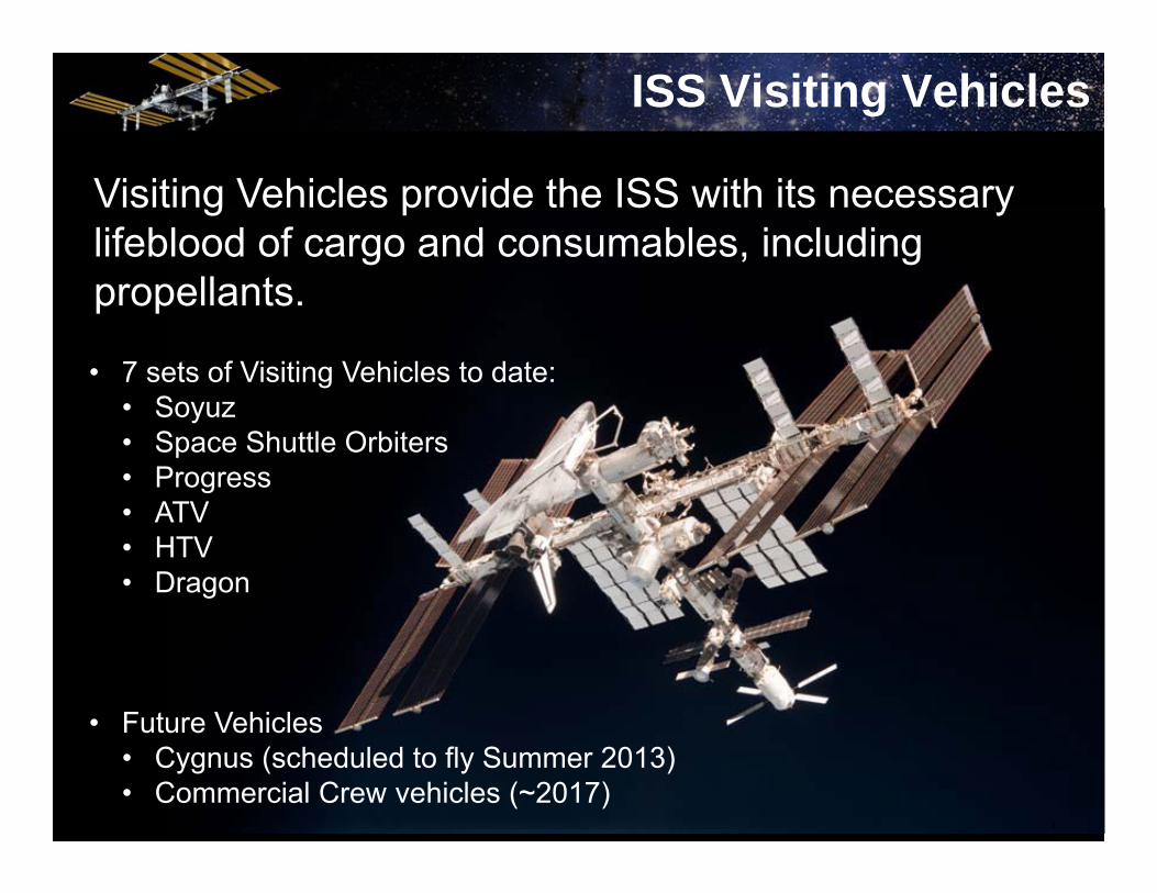
ISS Visiting Vehicles
Visiting Vehicles provide the ISS with its necessary lifeblood of cargo and consumables, including propellants.
• 7 sets of Visiting Vehicles to date:• Soyuz• Space Shuttle Orbiters• Progress• ATV• HTV• Dragon
• Future Vehicles• Cygnus (scheduled to fly Summer 2013)• Commercial Crew vehicles (~2017)

5
ISS Visiting Vehicles
0
50
100
150
200
11/1/1998 7/28/2001 4/23/2004 1/18/2007 10/14/2009 7/10/2012
Mat
ed M
issi
on L
engt
h, D
ays
Date
ISS Visiting Vehicle Flights
Soyuz Missions (34)
Shuttle Missions (37)
Progress Missions (49)
ATV Missions (3)
HTV Missions (3)
Dragon Missions (3)

6
Soyuz
• Primary (current) crew vehicle flying to the ISS.
• Can provide propulsive control to ISS in off-nominal cases
• Docks autonomously using its own propulsion system
• Flown 34 ISS Missions
• Propellant: UDMH and NTO
• Pressurant: Helium

7
Orbiter (Space Shuttle)
• Primary US crew vehicle until retired
• Provided propulsive support during mated missions
• Docked autonomously using its own propulsion system
• Flown 37 ISS Missions
• Propellant (OMS and RCS): MMH and NTO
• Pressurant: Helium
8
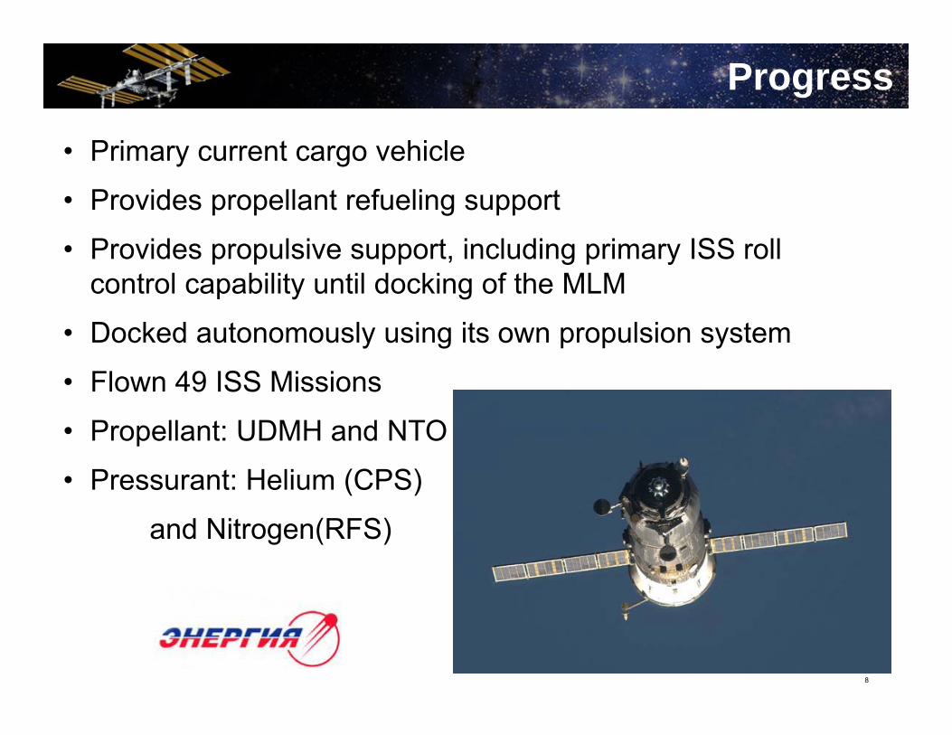
Progress
• Primary current cargo vehicle
• Provides propellant refueling support
• Provides propulsive support, including primary ISS roll control capability until docking of the MLM
• Docked autonomously using its own propulsion system
• Flown 49 ISS Missions
• Propellant: UDMH and NTO
• Pressurant: Helium (CPS)
and Nitrogen(RFS)
9
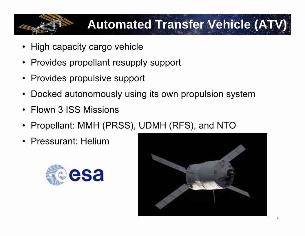
Automated Transfer Vehicle (ATV)• High capacity cargo vehicle
• Provides propellant resupply support
• Provides propulsive support
• Docked autonomously using its own propulsion system
• Flown 3 ISS Missions
• Propellant: MMH (PRSS), UDMH (RFS), and NTO
• Pressurant: Helium
10
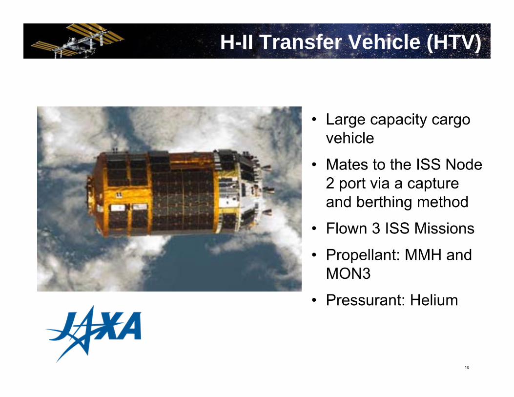
H-II Transfer Vehicle (HTV)
• Large capacity cargo vehicle
• Mates to the ISS Node 2 port via a capture and berthing method
• Flown 3 ISS Missions
• Propellant: MMH and MON3
• Pressurant: Helium

11
Dragon
• Commercially-developed US cargo vehicle
• Mates to the ISS Node 2 port via a capture and berthing method
• Only current returnable cargo vehicle
• Flown 3 ISS Missions
• Propellant: MMH and NTO
• Pressurant: Helium
12
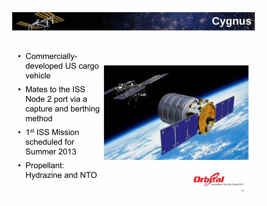
Cygnus
• Commercially-developed US cargo vehicle
• Mates to the ISS Node 2 port via a capture and berthing method
• 1st ISS Mission scheduled for Summer 2013
• Propellant: Hydrazine and NTO
13
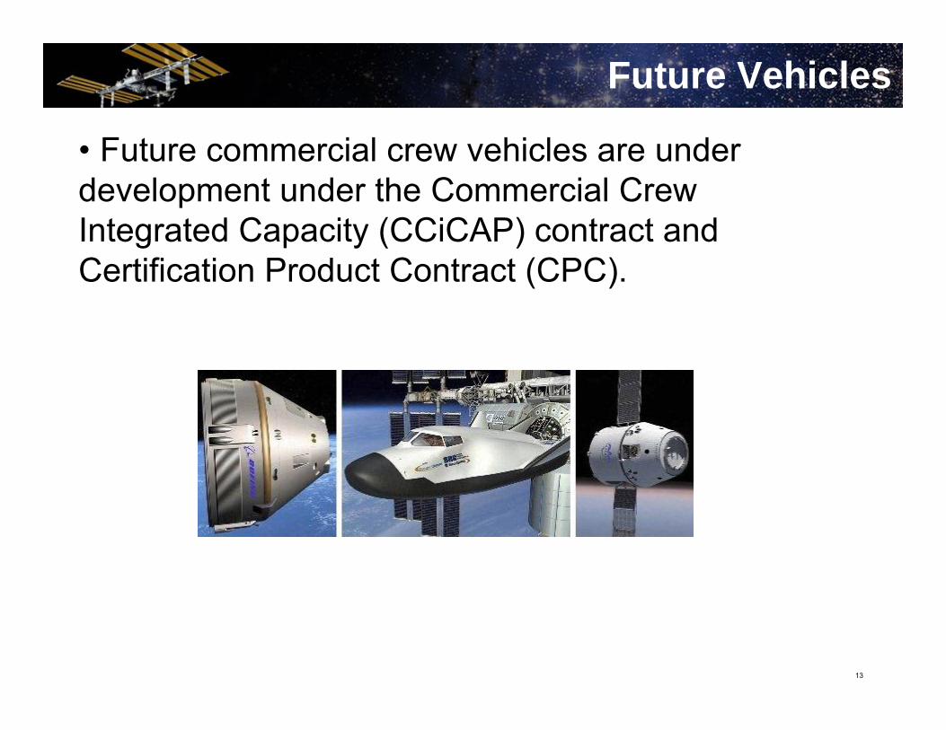
Future Vehicles
• Future commercial crew vehicles are under development under the Commercial Crew Integrated Capacity (CCiCAP) contract and Certification Product Contract (CPC).
14
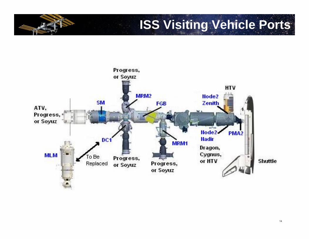
ISS Visiting Vehicle Ports

15
1.Crew Safety
2. ISS safety
3. Protection of ISS lifetime
4. Protection of ISS docking and berthing
capability
5. Visiting Vehicle safety
6. Mission success
Visiting Vehicle Priorities
16
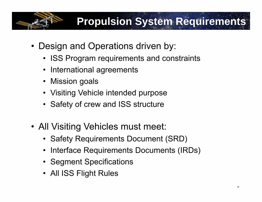
• Design and Operations driven by:• ISS Program requirements and constraints• International agreements• Mission goals• Visiting Vehicle intended purpose• Safety of crew and ISS structure
• All Visiting Vehicles must meet:• Safety Requirements Document (SRD)• Interface Requirements Documents (IRDs)• Segment Specifications• All ISS Flight Rules
Propulsion System Requirements

17
Sample Propulsion System Design

18
• Hazard Control – the use of design and operational measures to reduce the likelihood of hazardous effects
• Hazard Control includes:• Hazard Elimination• Damage Control• Containment• Isolation of potential hazards• Failure tolerance considerations• Incorporation of safety devices• Crew operational procedures• Protective clothing and equipment
Hazard Control

19
• Most common propulsion system hazards:• Collision• Contamination• Explosion
• Two categories of hazards:• Catastrophic – hazard resulting in disabling or fatal
crew injury, or loss of ISS or Orbiter• Critical – hazard resulting in non-disabling crew
injury, severe occupational illness, loss of a major ISS life-sustaining element, or damage to the Orbiter or ground facility
Hazard Control
20
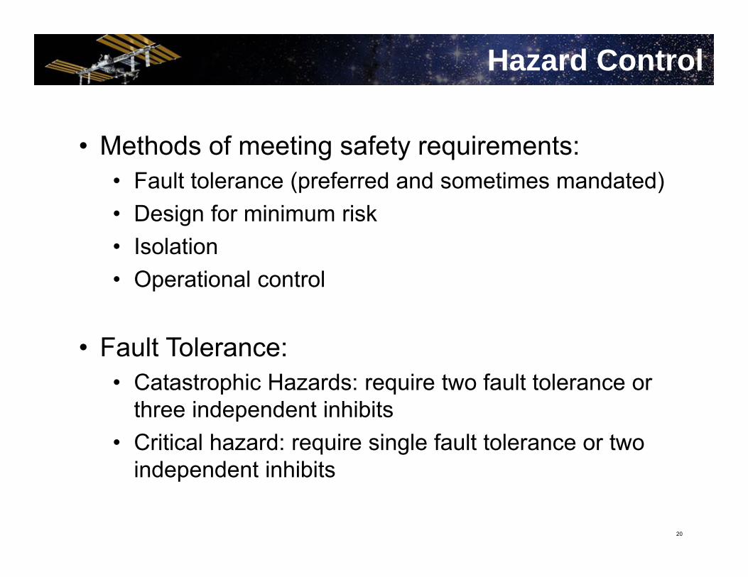
• Methods of meeting safety requirements:• Fault tolerance (preferred and sometimes mandated)• Design for minimum risk• Isolation• Operational control
• Fault Tolerance:• Catastrophic Hazards: require two fault tolerance or
three independent inhibits• Critical hazard: require single fault tolerance or two
independent inhibits
Hazard Control
21
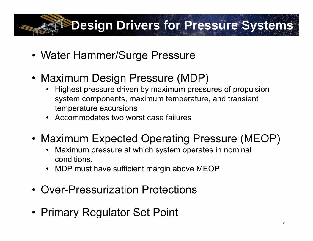
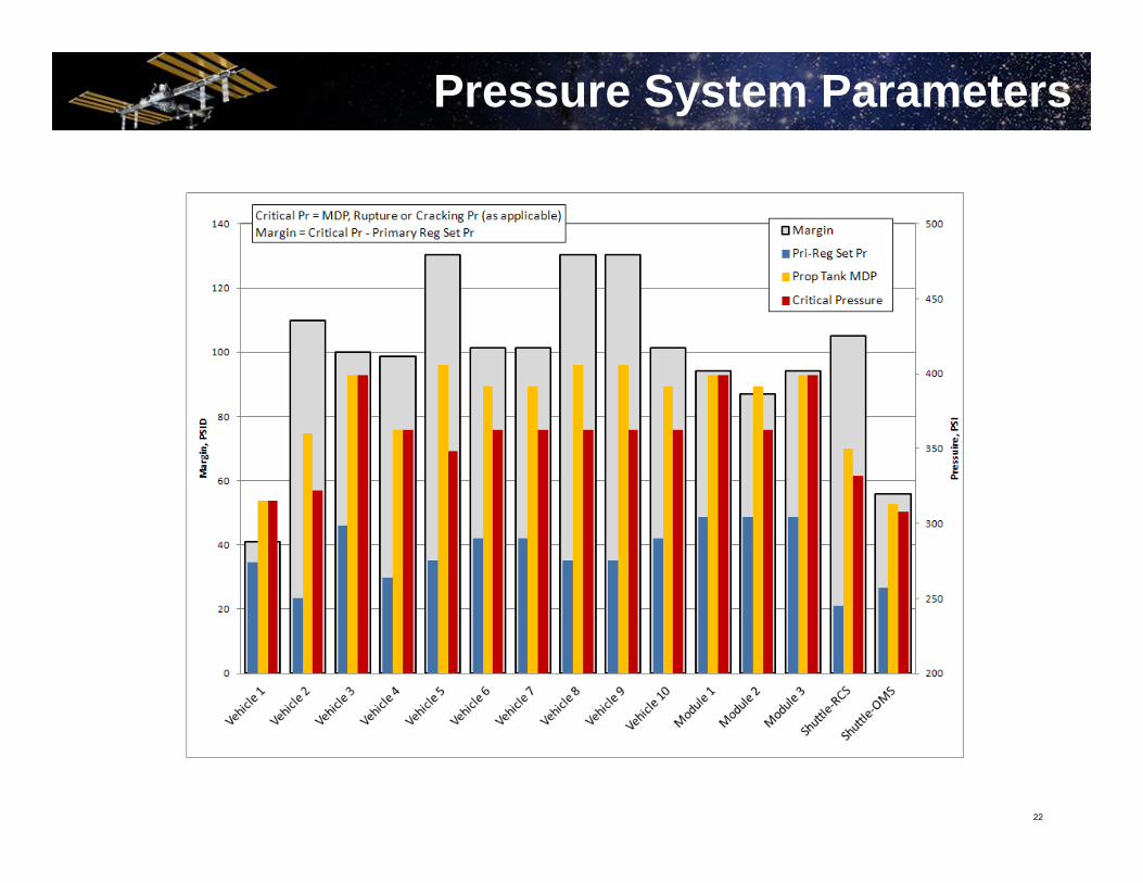
• Water Hammer/Surge Pressure
• Maximum Design Pressure (MDP)• Highest pressure driven by maximum pressures of propulsion
system components, maximum temperature, and transient temperature excursions
• Accommodates two worst case failures
• Maximum Expected Operating Pressure (MEOP)• Maximum pressure at which system operates in nominal
conditions.• MDP must have sufficient margin above MEOP
• Over-Pressurization Protections
• Primary Regulator Set Point
Design Drivers for Pressure Systems
22
Pressure System Parameters

23
NTO Tank Over-Pressurization Potential

24
• Flight rules:• Developed in a joint effort by MOD, ISS engineering
specialists, and vehicle owners
• Integrate relevant engineering constraints
• Outline procedures for nominal mission operations
• Assign responsibility and authority
• Plan a course of action for potential contingencies and anomalies
Integration and Operations – Flight Rules

25
• 4 primary propellant quantity gauging methods
• PVT method• Uses ideal gas law
• BTI method• m = consumption in kg• F = thrust in kgf• Ton = total on-time in seconds• Isp = specific impulse• Pavg = the average pressure of all tanks feeding the thruster in kg/cm2
• K1 and K2 = constants derived from the acceptance test data for each type of thruster
• Radio frequency method• Physical measuring device utilizing properties of diaphragm tanks
Propellant Quantity Gauging
m = F * Ton/IspF = (K1 * Pavg) + K2
PV = nRT

26
Integration and Operations
• System priming• Flight in regulated vs blowdown mode• Thruster failure detection and reaction• Docking vs Capture and Berthing• Thruster inhibits during docked or berthed phase• Propulsive support – attitude control and translation• Russian Control• USTO• Loads and structural concerns• Propellant resupply• ISS atmosphere contamination• Abort capability
27
ISS Propulsive Support
• Commanded by Service Module computers
• 2 modes:• Russian Segment Motion Control System (RS MCS)• US – Thrusters Only (USTO)
• Roll Attitude Control• Service Module• Progress at DC-1 Nadir or MRM2 Zenith• MLM (scheduled for launch in Dec 2013)
• Pitch/Yaw Attitude Control• Service Module• Progress at SM-Aft• ATV at SM-Aft
28
ISS Propulsive Support
• Significant portion of ISS thruster control is dedicated to translational control (mostly reboosts)
• Translational control• Progress R&D thrusters at SM-Aft• ATV thrusters (OCS or ACS) at SM-Aft• SM Main Engines• Progress Mid-Ring thrusters at DC-1 Nadir
(∆V ≤ 0.7 m/s only)
29
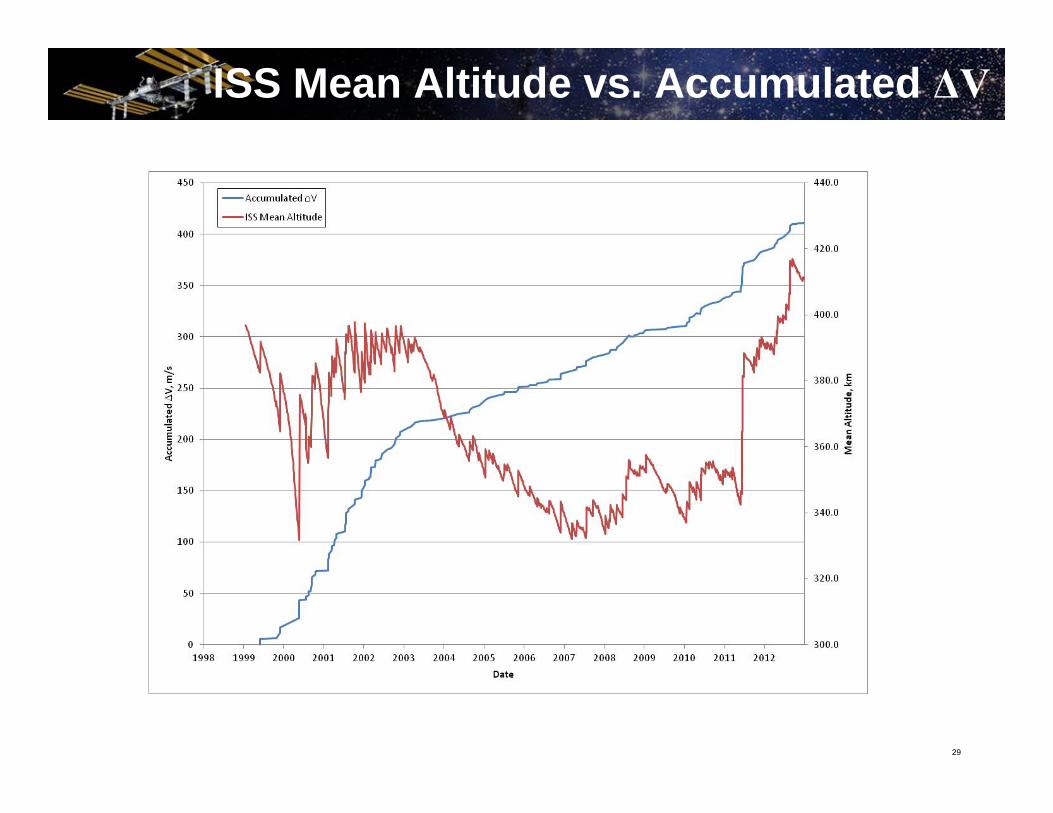
ISS Mean Altitude vs. Accumulated ΔV
30
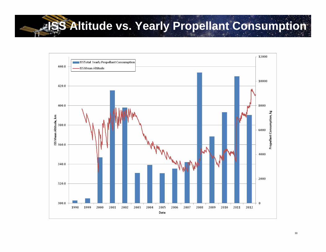
ISS Altitude vs. Yearly Propellant Consumption
31
ISS Refueling Support
• ISS Total On-Orbit Propellant Capacity = 7460 kg• Maximum Propellant Capacity of FGB = 6600 kg• Maximum Propellant Capacity of SM = 860 kg
• Total Propellant consumed over ISS Program:nearly 80,000 kg
• Propellant provided by Visiting Vehicles:~75,000 kg

32
ISS Propellant Load vs. Yearly Prop Consumption
33
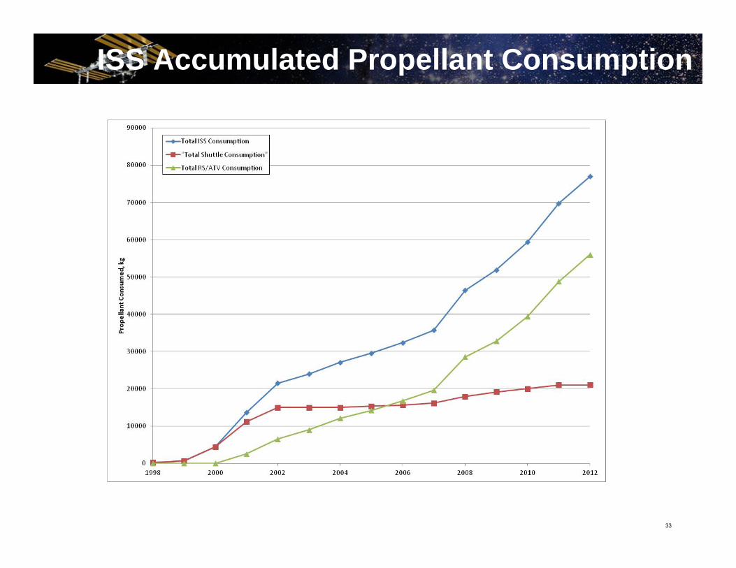
ISS Accumulated Propellant Consumption
34
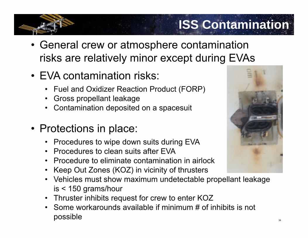
ISS Contamination• General crew or atmosphere contamination
risks are relatively minor except during EVAs• EVA contamination risks:
• Fuel and Oxidizer Reaction Product (FORP)• Gross propellant leakage• Contamination deposited on a spacesuit
• Protections in place:• Procedures to wipe down suits during EVA• Procedures to clean suits after EVA• Procedure to eliminate contamination in airlock• Keep Out Zones (KOZ) in vicinity of thrusters• Vehicles must show maximum undetectable propellant leakage
is < 150 grams/hour• Thruster inhibits request for crew to enter KOZ• Some workarounds available if minimum # of inhibits is not
possible

35
Abort Capability
• Abort capability necessary to protect against propulsion system failure or malfunction:• Unsafe trajectory• Loss of pressurization during regulated mode• Thrusters failures• Delay in departure burn• Etc.
36
• Visiting Vehicles are necessary for continued operation of the ISS.
• Each Visiting Vehicle is able to meet all the ISS safety and mission requirements through their unique vehicle design.
• Sufficient margins are built into their design to account for worst-case on-orbit conditions.
• VVs have provided the bulk of the total ISS propellant consumed since the FGB was launched in 1998 with a total of ~70,000 kg
• Using the requirements laid out in the SRD, IRD, and the flight rules, the ISS Program has successfully docked or berthed visiting vehicles over one hundred and twenty times throughout the fourteen years of its life.
• United effort on part of all international and commercial partners in design and operation of visiting vehicles is vital to the continued operation of the ISS.
Conclusion
37
Sources1. Beisner, M., Kamath, U.P., Swanson, R.A., “HTV Propulsion Systems Databook”, The Boeing Company,
Publication No. D684-13625-01 Rev A, Houston, TX, Mar. 2011. Cincinnati, OH, July 2007.
2. Cross, A., Duffin, S., and Greenberg, Z. “Transient Surge Pressure Characterization of a Spacecraft Propulsion Subsystem due to Propellant Priming and Thruster Valve Cycling”, JANNAF, JANNAF 2012-0001I, San Antonio, TX, May 2012.
3. “Interface Definition Document (IDD) for International Space Station (ISS) Visiting Vehicles (VVs)”, NASA, SSP 50235, Houston, TX, Feb. 2000.
4. “International Space Station (ISS) to Commercial Orbital Transportation Services (COTS) Interface Requirements Document (IRD)”, NASA, SSP 50808, Houston, TX, July 2007.
5. Karakulko, W., Russell, S., Sanders, G.B., Spencer, V., “Russian Propulsion and Propellant Resupply Systems for the ISS”, NASA, JSC-27979 Rev. F, Houston, TX, Mar. 2010.
6. Kamath, U., Metrocavage, K., Russell, S., Spencer, V., Swanson, R.A., “On-Orbit Propulsion and Methods of Momentum Management for the International Space Station”, AIAA, AIAA 2009-4899, Denver, CO, Aug. 2009.
7. Kamath, U.P., Krajchovich, M.C., Swanson, R.A., “ATV Propulsion and Propellant Resupply Systems Databook”, The Boeing Company, Publication No. D684-13250-01, Houston, TX, Jan. 2009.
8. Keyser, L., “Apollo Experience Report – the Role of Flight Mission Rules in Mission Preparation and Conduct”, NASA TN D-7822, Houston, TX, Nov. 1974.
9. Pedley, M.D., Internal Note to NASA EVA Project Office, “Propellant Contamination Issues – Potential Hazards to Crew”, NASA, Houston, TX, Feb. 2001.
10.“Safety Requirements Document”, NASA, SSP 50021 DCN 004, Houston, TX, July 2009.
11.“Space Systems – Composite Overwrapped Pressure Vessels (COPVs)”, ANSI/AIAA, S-081A-2006, Reston, VA, July 2006.
12.Yamamoto, M., Nakai, S., Ishizaki, S., Matsuo, S., Imada, T., Russell, S., and Kamath, U.,“Surge Pressure Management in HTV Propulsion System,” 43rd AIAA/ASME/SAE/ASEE Joint Propulsion Conference & Exhibit, “Structural Design and Verification Requirements”, NASA, SSP 30559 Rev D, Houston, TX, July 2007.


