

Proposal for Restoration of the Salton Sea “Scientific Geothermal Technology”
– Power Point Presentation – SMU – Power Plays Conference, Dallas, TX - May 18-20, 2015
Author: Nikola N. Lakic, Graduate Engineer Architect,
GEOTHERMAL WORLDWIDE, INC.
78-365 Hwy 111, #402, La Quinta, CA 92253
www.GeothermalWorldwide.com
760-347-1609

Summary of the Proposal for Restoration of the Salton Sea
GEOTHERMAL WORLDWIDE, INC.
Phase I: Connecting the Salton
Sea with Pacific Ocean with pipelines for
controlling waterline level of the lake and
exchanging waters and providing
conditions for tourism.
Phase II: Production of two sets of
dikes – one in northern and one in
southern part of the Salton Sea forming
ponds for treatment of farmland runoff
water and providing wildlife sanctuary,
and separating (now) oceanic water in
the central part of the lake.
Phase III: Production of the first
Power Plant with SCI-GHE system
using geothermal sources for
production of electricity and fresh
water.
Phase IV: Production of two
additional power plants on two
additional sectors.
Phase V: Continued buildup of
subsequent Power Plants at each
sector.

Heat Exchanger
Heat Exchanger
GEOTHERMAL WORLDWIDE, INC.
The (SCI-GHE) apparatus is an integral part
of the "Self Contained In-Ground Geothermal
Generator" (SCI-GGG system) and is used
separately as an independent Heat Exchanger
apparatus.
The (SCI-GHE) apparatus consist of: two coils
(Heat Exchangers); a closed loop of thermally
insulated pipes/houses 72; at least one In-Line
Pump 172; and a Binary Power Unit 184.
The first coil (Heat Exchanger) 168 of the first
closed loop systems is located at the bottom of
the well at heat source and the second coil (Heat
Exchanger) 182 is coupled into boiler of the
Binary Power Unit on the ground surface which
operates as a second closed loop system - the
Organic Rankine Cycle (ORC) – which generates
electricity.
Alternatively, the (SCI-GHE) and/or (SCI-GHE)
apparatus can be scaled to be used for
extracting heat from abandon and marginal
wells.
The first coil (HE) at the bottom of well bore is
structurally sound and can support its weight.
The "Self Contained In-Ground Heat Exchanger” (SCI-GHE system)
GEOTHERMAL WORLDWIDE, INC.
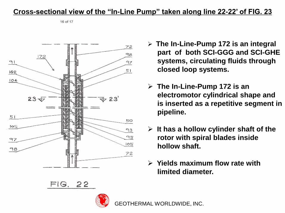
The In-Line-Pump 172 is an integral
part of both SCI-GGG and SCI-GHE
systems, circulating fluids through
closed loop systems.
The In-Line-Pump 172 is an
electromotor cylindrical shape and
is inserted as a repetitive segment in
pipeline.
It has a hollow cylinder shaft of the
rotor with spiral blades inside
hollow shaft.
Yields maximum flow rate with
limited diameter.
Cross-sectional view of the “In-Line Pump” taken along line 22-22’ of FIG. 23

GEOTHERMAL WORLDWIDE, INC.
Alternatively, the In-Line-Pump 172 can
be inserted as a repetitive segment of
a raiser pipe for pumping fluids up to
the ground surface from reservoirs in
which geo-pressure is low.
Also, the In-Line-Pump 172 can be used
in cross-country pipeline for oil, gas,
water, etc., as a repetitive segment.
In downhill route it function as a
generator and generates electricity,
which can be used to supplement In-
Line-Pumps 172 in horizontal and uphill
route.
Cross-sectional view of the In-Line Pump taken along line 23-23’ of FIG. 22

Schematic Cross-Sectional Diagram of an Universal Heat Exchange System 210
FIG. 24 illustrate an schematic cross
sectional diagram of an universal heat
exchange system 210 with main
segments including:
A thermally insulated close loop line
72 with an in-line pump 172;
A first heat exchanger 168 positioned
in heat source environment “A”; and
A second heat exchanger 182
positioned in preferred environment
“B”;
Heat is extracted from heat source
through the first heat exchanger 168
and transferred through thermally
insulated line 72 to the second heat
exchanger 182 for external use
including production of electricity.
The universal heat exchange system
210 is a portable unite and can be used
in many applications. GEOTHERMAL WORLDWIDE, INC.

Two posts/towers 192 and 194 erected on
either side of established lava flow/tube
196 with cable 193 suspended between
them.
The first heat exchanger 168 is lowered at
safe distance, close to lava flow 196, and
the second heat exchanger 182 is coupled
into boiler/evaporator 220 of the binary
power unit 180.
Heat exchangers 168 and 182 are
connected with thermally insulated closed
loop system 210.
Power unit 180 consist of a boiler 220 a
turbine 230, a generator 250, and a
condenser 260.
Cooling system for the condenser 260
consisting of additional closed loop
system 270 with heat exchanger 282
submerged into Ocean 165.
GEOTHERMAL WORLDWIDE, INC.
Schematic Plan View of a Power Plant for Production of Electricity in locations
such as Hawaii by using SCI-GHE System

Flare stack 137 has support structure 138.
The heat exchange system 210 with the first
heat exchanger 168 positioned on top of the
supporting structure 138 and the second heat
exchanger 182 coupled into boiler/evaporator
220 of the binary power unit 180.
Heat from flame 139 is extracted through the
first heat exchanger 168 and transferred
through thermally insulated line 72 to the
second heat exchanger 182.
Binary power unit 180, has a boiler 220,
turbines 230, a generator 250, and condenser
260.
Condenser 260 is cooled with additional
closed loop system 270 consisting of the first
heat exchanger 268, closed loop line 272 and
the second heat exchanger 282 which can be
submerged into nearby source of cold water.
Cross-sectional view of a Power Plant for Production of Electricity from heat
source such as Oil Well Flare Stacks by using SCI-GHE System
GEOTHERMAL WORLDWIDE, INC.
GEOTHERMAL WORLDWIDE, INC.
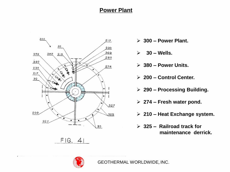
Power Plant
300 – Power Plant.
30 – Wells.
380 – Power Units.
200 – Control Center.
290 – Processing Building.
274 – Fresh water pond.
210 – Heat Exchange system.
325 – Railroad track for
maintenance derrick.

GEOTHERMAL WORLDWIDE, INC.
Cross-Sectional view of one Power Unit – SCI-GHE System
30 - Well.
240 - Derrick.
380 - Power Units.
210 - Heat Exchange system.
217 - Boiler / Distiller.
230 - Turbine.
360 - Condenser.
250 - Generator.
312 - Inflow cooling line –
water from canal.
314 - Outflow cooling line.
256 - Condensed fresh water line.


