
33
ByLeo H.M. Van Zuilen
Da~id J. FieldingGeorge C. Driscoll, Jr.
Beam-to-Column Connections
fritz Engineering Laboratory Report No. 333.4
PROPOSAL FOR TESTSO,F FULL SIZE BEAM-TO-COLUMN
CONNECTIONS SUBJECTED TOMOMENT, SHEAR, AND
HIGH AXIAL LOADS
Beam-to-Column Connections
PROPOSAL FOR TESTS OF FULL SIZE
BEAM-TO-COLUMN CONNECTIONS
SUBJECTED TO MOMENT, SHEAR,
AND HIGH AXIAL LOADS
by
Leo H. M. Van Zuilen
David J. Fielding
George C. Driscoll, Jr.
This work has been carried out as part ofan investigation sponsored jointly by theAmerican Iron 'and Steel Institute and theWelding Research Council.
Fritz Engineering LaboratoryDepartment of Civil Engineering
Lehigh UniversityBethlehem, Pennsy~vania
August 1968
Fritz Engineering Laboratory Report No. 333.4

333.4
TABLE OF CONTENTS
-i
Page
1. INTRODUCTION 1
1.1 Past Work 1
2. THE GEOMETRY OF THE CONNECTION SUBASSEMBLAGE 4
2.1 The Choice of the Members 4
2.2 The Geometry of the Connection Subassemblages 6
2.3 The Test Set-Up 7
3. INSTRUMENTATION 8
4. THE TESTING PROCEDURE 10
5. SUMMARY 11
6. FINANCES ~2
7. FIGURES 13
8. REFERENCES 19
333.4 -1
1. INTRODUCTION
The work done on the analysis of beam-to-column connections
before 1962 did not take into consideration the combined effect
of shear, axial load and moment. It should be expected, however,
that the high axial loads, which occur in the lower parts of
multi-story frames, affect the behavior of the connections consi
derably. In fact, during tests on subassemblages of mUlti-story
frames it was observed that the shearing deformation of beam-to
column connections was largest for the connections with the highest
axial loads, though the shear forces and the moments were equal
for all connections.(l)
Some of the connections tested had diagonal stiffeners to
resist shearing deformation. In some of these connections tested
under a relatively high axial load, yidlding occurred in the
stiffener before the plastic moment in any of the adjacent members
had'been reached.
The current AISC design specifications, however, do not take
into consideration this influence of the axial load on the behavior
of beam-to-column connections.
1.1 Past Work
The first study to include these effects was done at the
University of Tokyo by T. Naka et al. (2 ) This project was limited
to the elastic range.
333.4
In 1966 a research project on the behavior of beam-to-column
connections was initiated at Lehigh University sponsored jointly
by the American Iron and Steel Institute and the Welding Research
Council.
-2
A series of 7 pilot tests on small size beam-to~column
connections, salvaged from earlier tests on multi-story frames was
done. Special attention was given to the .behavior of the specimen
subassemblages in the plastic range. This series of tests included
unstiffened connections and stiffened connections with diagonal
stiffeners in compression or tension. At the same time a theore-
tical study was started, including both upper and lower bound
solutions. The results of the series of experiments and of the
theoretical work have been reported. (3) A report describing
recent progress on theoretical wo'rk is under preparation .. ( 4 )
Both the test·results and the theoretically derived expressions
show a considerable influence of the axial load in the column on
the behavior of the connection. Therefore a modified design
procedure which takes care of this effect has been suggested.
On the basis of the results of the series of pilot tests done
last year and of the theoretical work, a list· of recommendations
for future work on this topic has been assembled.(3) One of the
major points of these recommendations was to investigate both
theoretically and experimentally the influence of the size of a
connection on its behavior.
333.4 -3
Therefore, tests are needed on connections of practical size
to check the theoretically derived expressions for the influence
of the dimensions on the behavior of the connections. In particular,
the influence of the thickness of the flanges of the column on the
resistance against shearing deformation of the connection should be
investig~ted. On the basis of the theoretically derived expressions
a considerable influence must be expected for heavy columns. The
information obtained from these tests on full-scale connection sub
assemblages, and the results of the theoretical study will then be
used to evaluate the present design formula, and, if desirable, to
develop an alternative design method.
In the following chapters of the report, a pilot test is pro
posed for a series of tests on full-scale connection subassemblages.
Objectives of ~his pilot test are to check, and, if necessary,
to improve the following items:
1) The geometry of the connection subassemblage to be tested.
2) The test setup
3) The instrumentation
4) The test procedure.
The experience obtained, from this pilot test on a full-size
specimen and from the previous series of tests on small-sized
specimens will be used for the final preparation of the series of
tests on fUll~size specimens, to be executed during spring 1969.
333.4 -4
2. THE GEOMETRY OF THE CONNECTION SUBASSEMBLAGE
2.1 The Choice of the Members
The test is to be made on a connection subassemblage consist-
ing of an appropriate combination of a beam section and a column
section. The choice of members in the connection subassemblage is
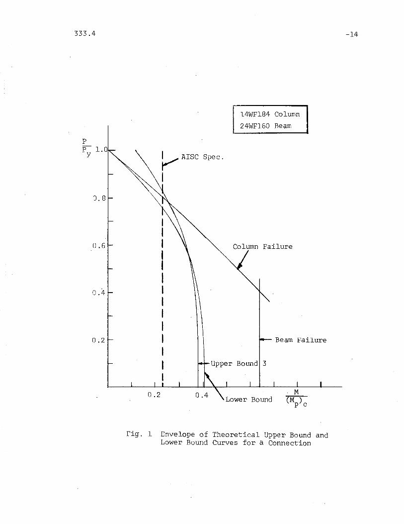
to be based on theoretically derived interaction curves for the\
thrust and the bending moment applied to the subassemblage. These
curves consisted of a number of upper bound and lower bound
solutions for the failure of connection subassemblages. The upper
bound solutions are based on several assumed mechanism patterns.
An envelope of the solutions is plotted to form a shaded area in
Fig. 1. The functions are plotted in terms of P/Py the ratio of
column thrust to yield thrust, and (M/M) 1 the ratio of columnp co
moment to its plastic moment. The solutions are compared with a
line defining the failure solution implied by the plastic design
provisions of the 1963 AISC·Speriification. A report on the theore
tical derivation of the solutions is under preparation.(4)
A test connection designed to observe the phenomena of interest
during connection failure should satisfy' the following conditions:
1) No failure should occur in the beam.
2) No failure should occur in the column outside the
connection.
3) The beam and the column should form a connection of a
realistic shape and size.
333.4 -5
The first condition requires a beam with a sufficient plastic
modulus,. This plastic modulus must be found in the thickness of
the flanges rather than in the depth of the beam. An increase of
the depth of the beam would increase the strength of the actual
connection proportionally, so that the danger of a failure in the
beam before the connection fails is not diminished. The safety
factor against failure outside the actual connection must be ample,
since strain hardening has not been taken into account in deriving
the interation curve for the connection. Therefore, of beams with
equal depths, only those with the largest thickness of the flanges
have been taken into consideration.
As can be seen in Fig. 1, the interaction curves for the actual
connection and for the column outside the connection are very close
for relatively high P/Py ratios. This is not appreciably influenced
by the size of the column. Therefore, in order to diminish the
danger of failure in the column outside the connection before the
actual connection fails, the pip ratio must be kept smaller than 0.6.y
The combination of beam and column must be realistic. Though
the forces on the specimen subassemblage must leave an ample safety
margin during the pilot test, they must be large enough to make a
proper evaluation of the behavior of the test setup possible.
It is expected, that a connection subassemblage consisting of
a 24WF160 beam and a 14WF184 column will fulfill these requirements
satisfactorily.
333.4 -6
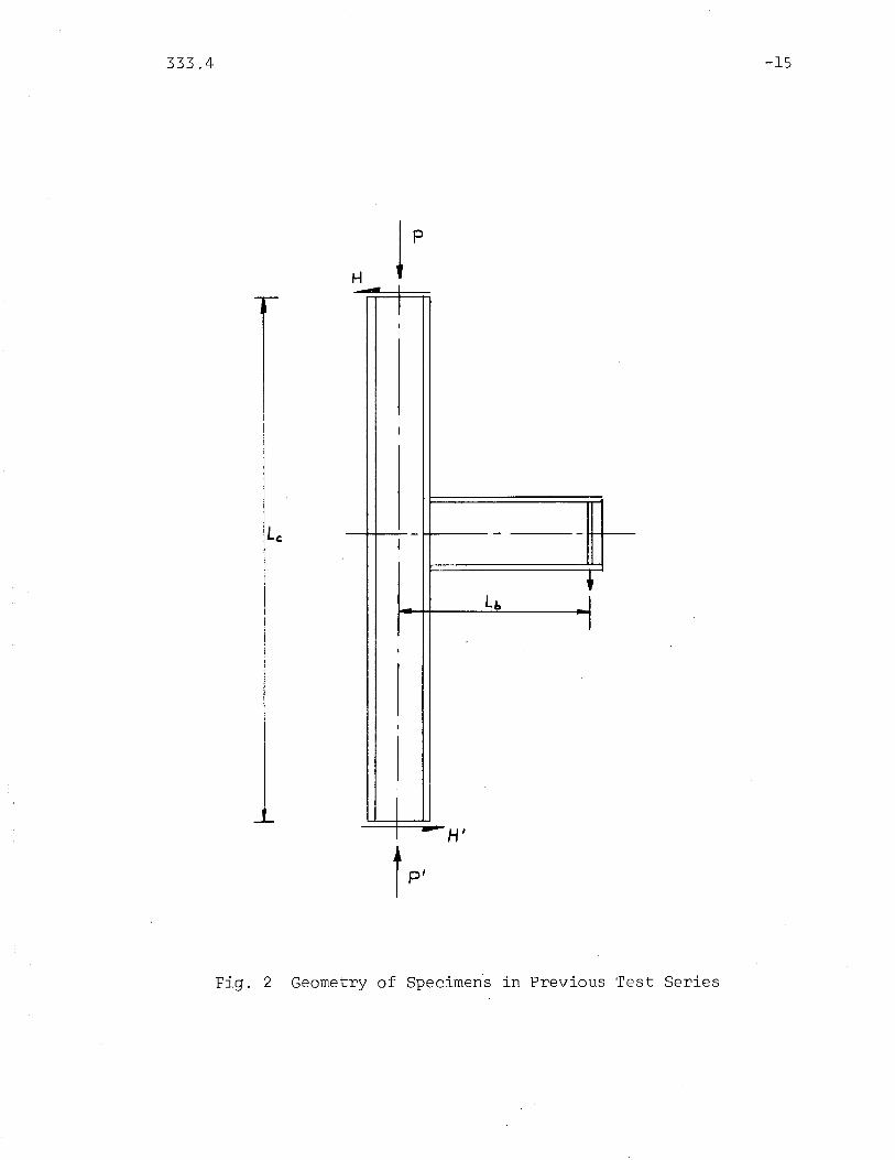
2.2 The Geometry of the Connection Subassemblages
The geometry of the specimens of the previous series is shown
in Fig. 2. It was satisfactory except for the following points:
1) Local buckling occurred in both the beams and the
columns.
2) The length of the column was too short. As a
result, the shear force in the column was high and
cancelled out a large part of the shear force in
the connection.
These two factors generally caused failure of the connection
subassemblage outside the actual connection. The AISC design
formulas have been used to check for local buckling during this
test. It is expected that the shear force in the column will be
reduced sufficiently by taking a length of the column between
inflection points of lOr.
The length of the beam may be determined later. Factors in
this decision are the capacity and stroke of the available jack,
and the difference between the axial loads in the top and bottom
parts of the column.
Except for these changes, the geometry of the specimen of the
pilot tests is similar to -the previously tested specimens. Hori
zontal stiffeners will be applied according to the AISC design
specification.
333.4 -7
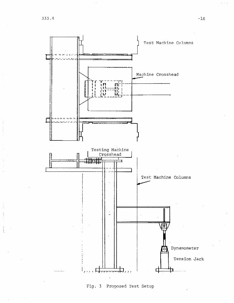
2.3 The Test Set-Up
The proposed test set-up is shown in Fig. 3. The axial load
in the column will be applied by a 5,000 kip universal testing
machine. The moment will be introduced into the connection by a
tension jack on the beam. Thus the loading condition of a floor
load on a frame is imitated.
It would be preferable to equip the specimen with pin-ends.
This would improve the stiffness of the specimen and more certainly
give the desired stress distribution. For the subassemblage to be
tested as a pilot test, the shear force at the ends of the column
would be in the order of 130 kips, while for heavier column shapes
these forces may reach 400 kips. In the past months an extensive
study has been made of the possibilities of adapting the pin-end
fixtures available at Fritz Labor~tory for these forces,. or to
obtain the desired pin action by other means, within the financial
limits of the project. No satisfactory solution has been found
however. Therefore the subassemblage column will have fixed ends.
The head of the testing machine would probably be jammed by the
large horizontal shear force in the column. Therefore the top end
of the column will be supported by a heavy beam with the strong axis
in the horizontal plane, which will conduct this force to the
columns of the testing machine (Fig. 3). The bottom end plate of
the column simply will be bolted down to the testing machine table.

333.4 -8
3. INSTRUMENTATION
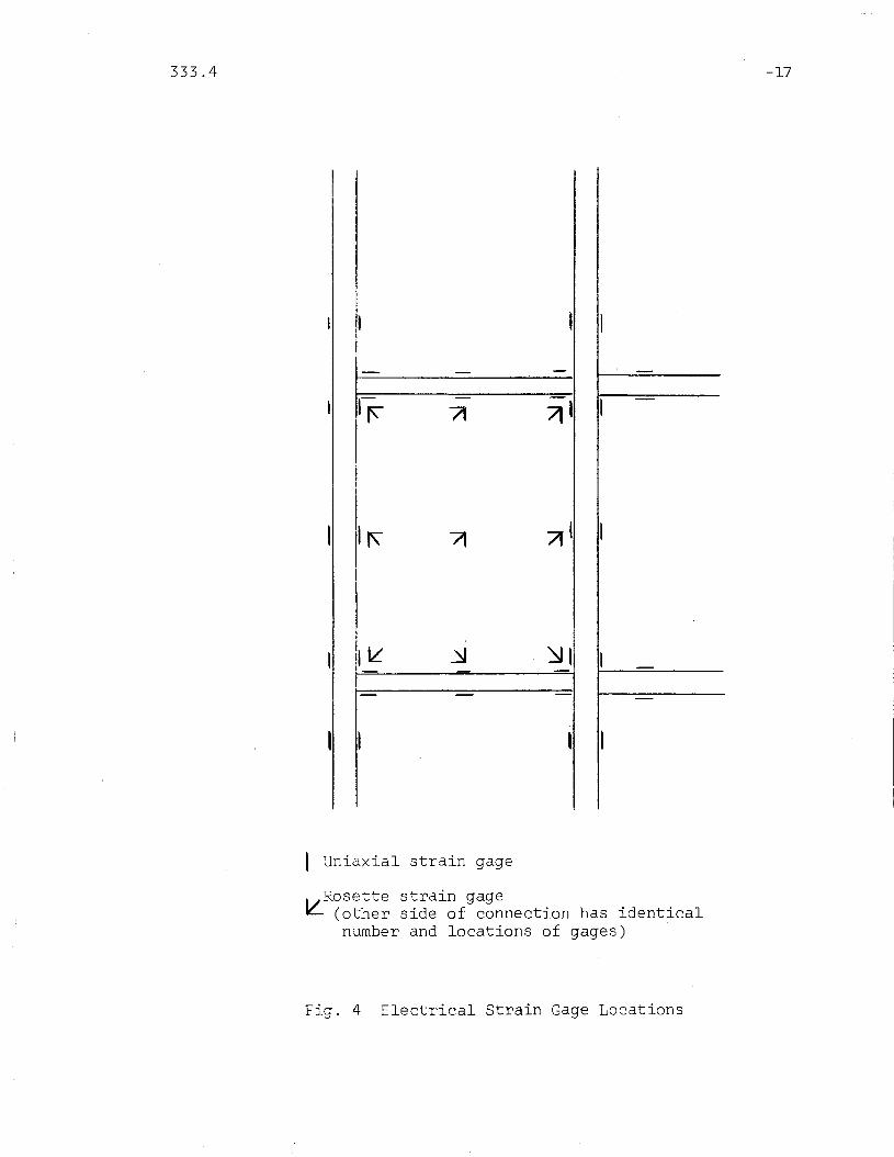
Each specimen will be instrumented with electrical resistance
strain gages at locations on the flanges of the column and the beam
and the horizontal stiffeners Rosette gages will be used for the
web panel of the connection, and the webs of beam and column near
the face of the connection (Fgi. 4).
Special care will be given to the instrumentation of the column,.
in order to be able to observe the influence of the difference in the
axial load in the upper and lower parts of the column.
The same'type of gages (SR4) will be used as in· the previous
series of tests. These gages make it possible to obtain strqin
readings well into the plastic region. The reading in the plastic
region however is only of qualitative value due to local effects.
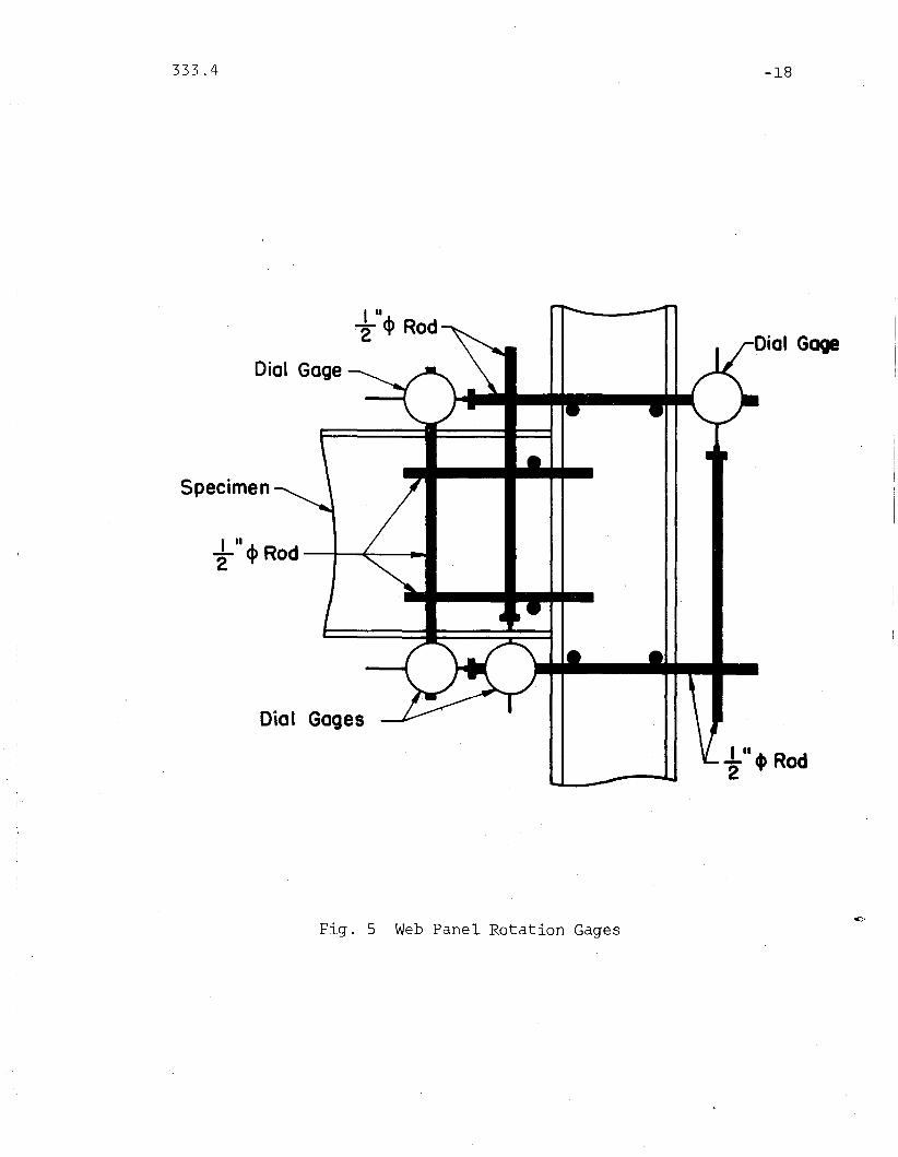
The absolute rotations of both the top and bottom end plate of
the column and of the end of the beam will be measured by 20 ft level
bars. The rotations of the top and bottom parts of the column and
beam relative to each other will be measured by a system similar to
that used in the previous test series.(3) (Fig. 5). This system
consists of rods which are spot welded to the web of the member at a
short distance from the joint. The displacements of these rods
relative to each other, will be measured by wires, which are
stretched between one rod and a dial gage mounted on another rod.
From these relative displacements the rotations can be calculated.
333.4 -9
The diagonal displacements of the web panel of the connection
will be measured in a similar way.
The deflection of the end of the beam will also be measured
using a wire stretched between a dial gage mounted on the beam and
the surface of the machine. Also, the relative deflections of the
flange of the column in the connection opposite the beam will be
measured by dial gages. This may give some additional information
about the failure mechanism of the connection.
The beam load applied by the hydraulic jack will be measured by
a dynamometer.
333.4 -10
4. THE TESTING PROCEDURE
Figure 3 shows a connection subassemblage ready to be tested.
First the specimen will be aligned, for which the gages at the four
flange edges at both the top and the bottom of the column will be
used. Alternatively, the location of the specimen in the universal
testing machine will be adjusted and a small moment will be applied
to the subassemblage in order to take the slack out of the end
fixtures.
Then the axial load on the column will be built up gradually
to about 0.5 P . The ratio pip is to be kept relatively low,y y
since for a higher axial load the interaction curves for the
specimen column and for the actual connection are very close.
Therefore for a Pip ratio larger than about 0.65 failure may occury .
in the column outside the connection. A test .in this region would
not provide information about connection strength.
After the desired axial load in the column is reached, the
beam load will be applied in steps. After each load increment the
axial load in the column will be adjusted to the desired value.
The beam deflection will be observed until it appears to be
constant, which will be taken as an indication that a stable state
has been reached.
Then all gages will be read. This procedure will be repeated
for each load increment.
333.4 -11
5. SUMMARY
The results of theoretical studies of welded beam-to-column
connections show a much higher ultimate strength than indicated by
the current design criteria. Also, high axial loads are expected
to have a considerable effect on the behavior of this type of
connections. This effect has not been taken into consideration by
the present design method. In order to check the theory and to
obtain more information about the behavior of the connections in
the plastic range, tests are needed.
In this report a pilot test is proposed on a full-size beam
to-column connection. The results of this pilot tests will be used
in the preparation of a series of tests on connections of practical
dimensions.
333.4 -12
6. FINANCES
The regularly contracted funds furnished for this project by
the American Iron and Steel Institute th~ough the Welding Research
Council will be used for this pilot test.

333.4 -l3
7. FIGURES
333.4 -14
14WF184 Column
24WF160 Beam
Upper Bound 3
Beam Failure
Column Failure
Lower Bound
0.4
0.6
0.2
p
P 1.0~AISCY Spec.
I0.8
Fig. 1 Envelope of Theoretical Upper Bound andLower Bound Curves for a Connection
333.4 -15
H
H,
~ I
II
I
- -..l. -I ,- LI:a I
1J
I
I
I1
....... ,
Fig. 2 Geometry of Specimen~ in Previous Test Series
333.4 -16
Test Machine Columns
_-:-_-:..-:..-......-:-_~-1-J===========:::I
-r r ...,r - - - -,-r'I tl n rTr-I---I, tl,L ~ 'I I'I ,. T - - -, Itt't IILI I'~ .__-J- L _L -. -- __=t:r ~--------
"
-.:;:..=..=. .=. -:::...::.:.. -=- -ti===============W
Testing MachineCrosshead
Test Machine Columns
Dynamometer
/ J I , 1 I /
Tension Jack
Fig. 3 Proposed Test Setup
333.4
, I
- - -
If'-
71 71 1
I" 71 7(1
lit ~ ~I
- - -
I I
I Uniaxial strain gage
Rosette strain gage~ (other side of connection has identical
number and locations of gages)
Fig. 4 Electrical Strain Gage Locations
-17
333.4
I U
~ <I> Rod
Dial Gage
Specimen
O'ial Gages
Fig. 5 Web Pan~l Rotation Gages
-18
..Ltld\ Rod
2 "
333.4 -19
8 . REFERENCES
1. Yura, J. A.THE STRENGTH OF BRACED MULTI-STORY FRAMES, FritzEngineering Laboratory Report No. 273.28, Ph.D.Dissertation, Lehigh University, September 1965(Available from University Microfilms, Inc"Ann Arbor, Michigan)
2. Naka, T., Kato, B., and Watabe, M.RESEARCH ON THE BEHAVIOR OF STEEL BEAM-TO-COLUMNCONNECTIONS, Laboratory for Steel Strurtures,University of Tokyo
3. Peters, J. W. and Driscoll, G. C., 0r.A 'STUDY OF THE BEHAVIOR OF BEAM-TO-COLUM:N CONNECTIONS,Fritz Engineering Laboratory Report No. 333.2, LehighUniversity, 1968
4. Van Zuilen, L. H. M., and Driscoll, G. C., Jr.A THEORETICAL STUDY OF BEAM-TO-COLUMN CONNECTIONS,Fritz Engineering Laboratory Report No. 333.5, LehighUniversity (In preparation)


