

Pumps & Accessories for the air conditioning and refrigeration industry
www.aspenpumps.com

46
aspen contents
designed by engineers for engineers...
Aspen was established in 1992 by
three engineers who were installing
air conditioning and refrigeration
equipment. This often proved to be
awkward with the existing products, so
we developed the peristaltic condensate
pumps to meet our own needs.
Since then Aspen Pumps have developed
a market leading range of pumps,
designed and manufactured
in the UK, for all conditions and
variable installations. The success has
been built by hands-on knowledge
of installation engineers.
6 20 28 30 38
Only Advanced Engineering’s indoor rangeof Coil Cleaners and condensate drain cleanare approved ‘pump safe’ by Aspen Pumps.
32
04 PERISTALTIC PUMPS
06 Universal
08 Standard
10 MK4 & Mechanical
12 Compressor Sensor
14 TANK PUMPS
16 Hi-flow
18 Hi-lift
20 Heavy Duty
22 Hot Water
24 MINI PUMPS
26 Mini Aqua
28 Mini Orange
28 Maxi Orange
30 Mini Lime
30 Maxi Lime
32 Lime Systems
34 SUPERMARKET PUMPS
36 ERRP & Cold Cabinet
38 Low Profile ERRP
40 Macerator
42 COLUMN PUMPS
44 PUMP ACCESSORIES
RECLAIM UNITS
46 EcoWarrior
48 EcoBuddy
50 CONTROLS
52
70

PER
ISTA
LTIC P
UM
PS
54
Peristaltic PumpsIn 1992 Aspen pioneered the use of Peristaltic condensatepumps and today are still setting the standard forreliability and innovation.
Peristaltic pumps offer the ideal solution
for condensate removal due to the
combination of quietness, reliability and
installation advantages. The Peristaltic
rotary movement generates a continuous
pressure meaning that the pump can be
sited over 15m away from the
condensate source with no effect on
performance. In addition, the pump
mechanism does not come into contact
with the water, removing the risk of
contamination or corrosion.
New & improved UniversalThe Universal peristaltic pump operates with two
temperature sensors. These allow the pump to detect
and be triggered by a change in air temperature,
making this pump suitable for many applications.
New & improved StandardThe Standard peristaltic pump is triggered by
the hard-wired cooling signal from the air
conditioning unit.
MK4The MK4 peristaltic pump operates using water level
sensors. This allows the pump to detect and be
triggered by the level of water in the condensate tray.
MechanicalThe Mechanical peristaltic pump operates by using a
remote reservoir with an internal float mechanism. It
is available with or without a high level alarm output.
Compressor SensorIdeal for applications where complete silence is
important. The Compressor Sensor pump is triggered
by a sensor, which is designed to be mounted onto the
compressor in an external condenser unit.
Peristaltic accessories are available on page 44
• QUIET OPERATION
• SITED AWAY FROM THECONDENSATE SOURCE
• RELIABILITY & LONG LIFE
• CAN RUN DRY

PER
ISTA
LTIC P
UM
PS
7
• Senses 5˚C differential across the evaporating coil
• Only requires live/neutral supply and 2 sensors either side of the evaporating coil – one ‘air on’ and one ‘air off’
• Operates only on cooling
• Self-priming lifts 3 metres
• 12 metres discharge head
• Water flow rate: 6.25 ltrs per hr@ 12 metres head
• 3 minute timer overrun
• No siphoning back
• No loud sound from dry running
• Manual test switch
• Pumps water, fibrously contaminatedwater and air
• Pump rating: 0.2A, 230V ACAlternative voltages available
• Connecting cable: 3 metres
• Fire retardant plastics
• Inlet /outlet size: 6mm
• Push-in plug
• Wall-mounted bracket
TECHNICAL SPECIFICATIONS
6
We recommend that you inspect the pump head regularly, andchange the pump head tube every12 months or more frequently if required.
SERVICE GUIDE
ELECTRICAL CONNECTIONS
INSTALLATION NOTES
The Universal peristalticpump operates with twotemperature sensors. Theseallow the pump to detectand be triggered by achange in air temperature,making this pump suitablefor many applications.
The Universal is designed to fit in ceiling
voids and lift the condensate water from
wall mounted machines where a gravity
drain is too obtrusive. It can also be
used on cassettes fitted with an internal
lift pump.
The pump can be mounted remotely
as it is self-priming to a height of
3 metres and will pump 6.25 litres of
water per hour against a maximum
head of 12 metres. The pump runs
constantly while the air conditioning
system is cooling – when the cooling
switches off a 3 minute timer ensures
that the condensate tray is emptied
before the pump switches off.
The Universal pump is a peristaltic
rotary type - which means that it is
quiet in operation, very reliable and will
run dry without fear of damage or
embarrassing noise. Unlike other pumps
using either mechanical or electrical
conductivity sensors, the Universal does
not suffer from corrosion or
contamination problems.
Product Height Width Depth Weight
115mm 135mm 77mm 1.35kgUNIVERSAL
PUMP DIMENSIONS
Connect the pump to the appropriate driptray (using the vinyl tube supplied), thenconnect to the mains power supply.Situate the red sensor in the ambient ‘airon’ side of the evaporating coil (NOTTOUCHING COIL). Position the bluesensor to the ‘air off’ side of theevaporating coil. This will sense 5ºCdifferential and operate the pump.
The pump is designed to sit level on itsbase and MUST at all times have adequatespace around it for good ventilation.
Ensure that there are no kinks or trappedparts in the piping, which must have a6mm I/D and a 9mm O/D. Fix the pipes withcable ties to the pump inlet and outlet.
PLEASE NOTE: where space is limitedlay and fix suction vinyl tube alongbottom of condense tray, as pump isself-priming.
A variable connector is provided to makeeasy installation between the condensatetray outlet and vinyl tube.
PUSH-IN PLUG
Brown Live
Blue Neutral
Green/Yellow
Earth
Universal
FP 2082/2
NEWIMPROVED SMALLERDESIGN

9
• Operates on hard-wired 150-230V cooling signal
• Self-priming lifts 3 metres
• 12 metres discharge head
• Water flow rate: 6.25 ltrs per hr @ 12 metres head
• 3 minute timer overrun
• No siphoning back
• No loud sound from dry running
• Manual test switch
• Pumps water, fibrously contaminated water and air
• Pump rating: 0.2A, 230V ACAlternative voltages available
• Fire retardant plastics
• Inlet /outlet size: 6mm
• Push-in plug
• Wall-mounted bracket
TECHNICAL SPECIFICATIONS
8
We recommend that you inspect the pump head regularly, andchange the pump head tube every12 months or more frequently if required.
All the peristaltics now come with a wall-mounted bracketwhich is designed to hold a replacement head tube for yourservicing convenience.
SERVICE GUIDE
Brown Live
Blue Neutral
Green/Yellow Earth
Black Switched live from signal
ELECTRICAL CONNECTIONS
INSTALLATION NOTES
The Standard peristalticpump is triggered by the hard-wired coolingsignal from the airconditioning unit.
The Standard is designed to fit in ceiling
voids and lift the condensate water from
wall mounted machines where a gravity
drain is too obtrusive. It can also be
used on cassettes fitted with an internal
lift pump.
The pump can be mounted remotely
as it is self-priming to a height of
3 metres and will pump 6.25 litres of
water per hour against a maximum head
of 12 metres.
The pump runs constantly while the air
conditioning system is cooling – when
the cooling switches off a 3 minute
timer ensures that the condensate tray
is emptied before the pump switches
off. Rollers in the pump act as check
valves to stop the condensate draining
back into the condensate tray.
The Standard pump is a peristaltic
rotary type - which means that it is
quiet in operation, very reliable and
will run dry without fear of damage or
embarrassing noise. Unlike other pumps
using either mechanical or electrical
conductivity sensors, the Standard
does not suffer from corrosion or
contamination problems.
Product Height Width Depth Weight
115mm 135mm 77mm 1.35kgSTANDARD
PUMP DIMENSIONS
Connect the pump to the appropriate driptray (using the vinyl tube supplied), thenconnect to the mains power supply, andcontrol link to the air-conditioning unitscooling signal.
PLEASE NOTE: The signal wire must beconnected to the cooling signal only.This ensures that when the system ison heating, the pump does not run.
The pump is designed to sit level on itsbase and MUST at all times have adequatespace around it for good ventilation.
Ensure that there are no kinks or trappedparts in the piping, which must have a6mm I/D and 9mm O/D. Fix the pipes withcable ties to the pump inlet and outlet.
A variable connector is provided to makeeasy installation between the condensatetray outlet and vinyl tube.
PER
ISTA
LTIC P
UM
PS
Standard
FP 2081/2
NEWIMPROVED
SMALLERDESIGN

11
MK4 • Operates on bead contact with water• 3 minute timer overrun
Mechanical • Operates on a float switch• 2 reservoir options available• Available with an alarm option
• Self-priming lifts 3 metres
• 12 metres discharge head
• Water flow rate: 6.25 ltrs per hr @ 12 metres head
• No siphoning back
• No loud sound from dry running
• Manual test switch
• Pumps water, contaminated water & air
• Pump rating: 0.2A, 230V ACAlternative voltages available
• Fire retardant plastics
• Inlet /outlet size: 6mm
• Push-in plug
• Wall-mounted bracket
TECHNICAL SPECIFICATIONS
10
The pump is designed to sit level on its base andmust at all times have adequate space around itfor good ventilation.
Ensure that there are no kinks or trapped partsin the piping, which must have a 6mm I/D andan 9mm O/D. Fix the pipes with cable ties to thepump inlet and outlet.
Both the MK4 and Mechanical share the same SERVICE GUIDE &ELECTRICAL CONNECTIONS as theUniversal peristaltic pump (see page 6).
MK4 INSTALLATION NOTES
The pump is designed to be mounted
remotely if required and has a 3 metre
(9.8ft) lead to the float switch. Simply
position the float switch in the
condensate tray or fix to the drain-pipe
connection (depending on chosen
reservoir). Then connect the reservoir
to the pump.
Connect the pump to the appropriate driptray (using the vinyl tube supplied), thenconnect to the mains power supply.
WATER LEVEL DETECTOR:When the unit is first switched on you needto allow 5 mins for the electronics to stabilise.
To ensure that the detector will operatesatisfactorily, please abide by the following:
1. The detector will trigger when thewater level has reached the first 2 or 3mmof the sensor, this should be taken intoaccount when positioning the height ofthe sensor. As the device works on heatconductivity it can take up to 30 secs forthe pump to switch on.
2. Position the sensor away from directdraught and make sure the tip is aminimum of 5mm from the base of thetray. Ensure the tip is in free air andunable to touch the sides. The ambientsensor within the cable 5cm from the tipcan be seen as a small disc beneath thesleeve, this should also be positioned infree air to avoid any heat conduction.
MECHANICAL INSTALLATION NOTES
Connect to the mains power supply.
Decide which reservoir is correct for yourinstallation and position the reservoir intothe condensate tray or to the drainpipeconnection (depending on whichreservoir you use).
Ensure you have placed the float magnet facing upwards. Then Connect the pump tothe reservoir (using the vinyl tube supplied).
ALWAYS ENSURE RESERVOIR IS MOUNTED HORIZONTALLY
The MK4 peristaltic pumpoperates using water levelsensors. This allows thepump to detect and betriggered by the level ofwater in the condensate tray.
The detector has two sensors within the
head which warm up to 15C̊ above
ambient. When the lower sensor comes
into contact with water, the heat
conductivity from the sensor provides a
temperature difference energising the
pump. Once the level of the water has
dropped below the tip of the sensor, the
pump will continue until the the sensor
has completely dried out.
The Mechanical peristalticpump operates by using aremote reservoir with aninternal float mechanism. It is available with orwithout a high level alarm output.
Product Height Width Depth Weight
145mm 160mm 83mm 1.7kgMK4 &MECHANICAL
PUMP DIMENSIONS
FP 2080FP 2078
(WITH ALARM) FP 2079
PER
ISTA
LTIC P
UM
PS
MK4 & Mechanical

1312
• Operates on 150-230V compressor signal
• Self-priming lifts 5 metres
• 12 metres discharge head
• Water flow rate: 6.25 ltrs per hr @ 12 metres head
• 3 minute timer overrun
• No siphoning back
• No loud sound from dry running
• Manual test switch
• Pumps water, fibrously contaminated water and air
• Pump rating: 0.2A, 230V ACAlternative voltages available
• Fire retardant plastics
• Inlet /outlet size: 6mm
• Push-in plug
• Wall-mounted bracket
• Mains cable: 3 metres
• Sensor cable: 10 metres
TECHNICAL SPECIFICATIONS
We recommend that you inspect the pump head regularly, andchange the pump head tube every12 months or more frequently if required.
SERVICE GUIDE
Brown Live
Blue Neutral
Green/Yellow
Earth
ELECTRICAL CONNECTIONS
INSTALLATION NOTES
Product Height Width Depth Weight
145mm 160mm 83mm 1.7kg
126mm 22mm 16mm 0.1kg
PUMP
SENSOR
PUMP DIMENSIONS
Decide where the pump will be locatedand connect it to the appropriate drip tray(using 6mm I/D vinyl tube), then connectto a 240V mains power supply.
Position the sensor vertically against thecompressor, so it protrudes above the topof the compressor like an aerial. This isimportant as it is where the electromagneticfield is strongest. Use the cable tie suppliedto fix the sensor securely to the compressor.A 10m sensor cable is supplied, which canbe extended if required.
The pump is designed to fit level on itsbase and MUST have adequate ventilationspace around it at all times.
Ensure that there are no kinks or trappedsections in the piping, which must have a6mm I/D and 9mm O/D. Fix the pipes withcable ties to the pump inlet & outlet.
A variable connector is provided to alloweasy fixing between the condensate outlet tray and the vinyl tube.
Ideal for applications where complete silence is important.
The Compressor Sensor pump is
triggered by a sensor, which is designed
to be mounted onto the compressor in
an external condenser unit. When the
air conditioning system starts up, the
compressor produces a localised electro-
magnetic field, triggering the sensor, which
in turn activates the peristaltic pump. The
pump runs constantly while the compressor
is operational. When the compressor
switches off, a 3 minute timer ensures
that the condensate tray is emptied
before the pump switches off.
Rollers in the pump act as check valves
to stop the condensate draining back
into the condensate tray.
The pump can either be fitted in the
ceiling void or installed within the
condenser unit (or nearby), as long as
the pump and it's plug/socket are
sheltered and fully protected from any
water ingress. The pump can be
mounted remotely in this way, as it is
self-priming to a height of 5m and will
pump 6.25L/h of water against a
maximum head of 12m. The Compressor
Sensor pump is a peristaltic rotary type -
which means that it is quiet in operation,
very reliable and will run dry without fear
of damage or embarrassing noise.
PER
ISTA
LTIC P
UM
PS
Compressor SensorFP 2584

1514
TAN
K P
UM
PS
Tank PumpsWhen looking for high flow rate, reliability and value formoney, Aspen tank pumps are the perfect solution.
• HIGH FLOW RATES
• BUILT IN HIGH LEVEL SAFETY
• HOT & COLD WATER OPTIONS
• VALUE FOR MONEY
Improved Hi-flow 1L & 2LHi-flow tank pumps are designed to collect condensate
water from refrigeration and air conditioning units.
They operate automatically when the float rises and
will discharge to a head of 4.6 metres.
Hi-lift 1L & 2LHi-lift tank pumps are designed to collect condensate
water from refrigeration and air-conditioning units.
They operate automatically when the float rises to
discharge to a head of 12 metres. The Hi-lift will
pump a smaller volume of water than the Hi-flow,
but to a greater head.
Heavy Duty 6m & 10mHeavy Duty pumps are designed for the rapid removal
of condensate. They are particularly useful in situations
where multiple refrigeration units are installed, or
where large refrigeration systems deposit considerable
quantities of condensate at one time.
Hot Water Heavy Duty & EconomyThe Hot Water Heavy Duty and Economy pumps are
designed to collect hot water from humidifier drain
down cycles and normal condensate water from any
associated air conditioning or boiler systems.
NEW, COMPACT HI-FLOW 0.5 LITRE TANK PUMPThe same market leading reliability of the Hi-flow
pump, for use when space is limited.
Tank pumps accessories are available on page 44
COMING
SOON
Aspen’s continued focus on innovation
has created a market leading range of
tank pumps, designed to suit a diverse
array of applications. With reliability
as the key decision criteria, the tank
pumps are designed to perform even
under the most challenging of
applications, including hot water.

Aspen’s Hi-flow tank pumps are designed
to collect condensate water from
refrigeration and air-conditioning units.
They operate automatically when the
float rises and will discharge to a head of
4.6 metres.
The Hi-flow will pump agreater volume of waterthan the Hi-lift, but to a lesser head.
The Hi-flows incorporate two high quality
switches, activated by a float system. One
operates the centrifugal type pump and
the other is used as a high level safety
switch. In the event of a pump failure
this device will switch off the refrigeration
unit and can simultaneously activate an
optional audio and/or visual alarm.
The deck of the pump is clear plastic
for quick and easy internal inspection,
and it comes with a 2 metre long
cable with push in plug which makes
installation and maintenance easier.
In all cases a tank pump must be sited
under the source of the condensate.
17
• Tank capacity: 1 litre or 2 litres
• 4.6 metres discharge head
• Water flow rate: 288 litres per hr max
• In-line valve to prevent siphoning back
• Pre-wired safety float switch
• Clear deck for quick and easy inspection
• Incorporated back-plate for vertical mounting
• Pump rating: 0.6A, 230V A.C.Alternative voltages available
• Auto-resetting thermal cut-out toshaded pole motor
• Connecting cable: 2 metres
• Safety switch 4.0A max
• Fire retardant plastics
• 2 inlet positions: 25mm ø
• Outlet size: 6mm x 10mm
TECHNICAL SPECIFICATIONS
Product Height Width Depth Weight
140mm 235mm 140mm 1.7kg
170mm 235mm 140mm 1.75kg
HI-FLOW1L
HI-FLOW2L
16
PUMP DIMENSIONS
300
250
200
150
100
50
00 1 2 3 4
FLO
W IN
LIT
RES
/HO
UR
HI-FLOW PERFORMANCE
METRES HEAD
Flush the pump thoroughly with anti-bacterial wash every 6 months to avoid sludge build-up in thepump housing.
SERVICE GUIDE
Brown Live
Blue Neutral
Green/Yellow
Earth
2x Black Safety switch
ELECTRICAL CONNECTIONS
2L: FP 2122 TAN
K P
UM
PS
Hi-flow 1L & 2L
NEWIMPROVED
DESIGNNow with 6mm & 10mm outlet barb
1L: FP 2096

Aspen’s Hi-lift tank pumps are designed
to collect condensate water from
refrigeration and air-conditioning units.
They operate automatically when the
float rises to discharge to a head of
12 metres.
The Hi-lift will pump asmaller volume of waterthan the Hi-flow, but to a greater head.
The pumps incorporate two high quality
switches, activated by a float system. One
operates the centrifugal type pump and
the other is used as a high level safety
switch. In the event of a pump failure
this device will switch off the refrigeration
unit and can simultaneously activate
an optional audio and/or visual alarm.
The pump is a peristaltic rotary type,
which means that it is quiet in operation,
very reliable and will run dry without fear
of damage or embarrassing noise.
Unlike other pumps using either
mechanical or electrical conductivity
sensors, the Hi-lift does not suffer from
corrosion or contamination problems.
The deck of the pump is clear plastic
for quick and easy internal inspection.
19
• Tank capacity: 1 litre or 2 litres
• 12 metres discharge head
• No siphoning back
• No loud sound from dry running
• Requires 230V supply only
• Water flow rate: 11 litres per hr@ 12 metres
• Clear deck for quick and easy inspection
• Fits into shallow ceiling void or unit
• Incorporated back-plate for vertical mounting
• Pump rating: 0.4A, 230V A.C.Alternative voltages available
• Pumps water, fibrously contaminatedwater and air
• 4 amps pre-wired safety switch
• Fire retardant plastics
• 2 inlet positions: 25mm ø
• Outlet size: 6mm
TECHNICAL SPECIFICATIONS
Product Height Width Depth Weight
132mm 235mm 140mm 1.8kg
165mm 235mm 140mm 2kg
HI-LIFT1L
HI-LIFT2L
18
PUMP DIMENSIONS
Inspect the pump head regularly andchange the pump head tube every12 months or more frequently ifrequired. Flush the pump thoroughlywith anti-bacterial wash every 6months to avoid sludge build-up inthe pump. This only takes 3 minutes!
SERVICE GUIDE
Brown Live
Blue Neutral
Green/Yellow
Earth
2x Black Safety switch
ELECTRICAL CONNECTIONS
15
12
9
6
3
00 3 6 9 12 15
METRES HEAD
FLO
W IN
LIT
RES
/HO
UR
HI-LIFT PERFORMANCE
1L: FP 2099
2L: FP 2071
Hi-lift 1L & 2L
TAN
K P
UM
PS

The Aspen Heavy Duty pumps are
designed for the rapid removal
of condensate. They are particularly
useful in situations where multiple
refrigeration units are installed, or
where large refrigeration systems
deposit considerable quantities of
condensate at one time.
The pump unit is robustly
constructed and designed to give
reliable performance. This is
particularly important in environments
where efficient cleanliness is of
utmost importance.
Two floats provide the operational
control, one to operate the pump,
and the other a safety float to be
wired into the refrigeration unit
control circuit.
The Heavy Duty tank pumps have a greaterwater flow rate than the Hi-flow tank pumps, for more heavy dutyapplications.
21
Heavy Duty 6m• 6 metre discharge head
• Power supply: 230V 1.5AAlternative voltages available
• Water flow rate: 900 litres per hr
Heavy Duty 10m• 10 metre discharge head
• Power supply: 230V 0.7AAlternative voltages available
• Water flow rate: 1250 litres per hr
• Tank capacity: 4 litres
• 6 &10 metre discharge head
• Non-return valve
• No siphoning back
• 4 amps pre-wired safety switch
• Plastic tank and pump unit fire retardant plastics
• 2 inlet positions: 40mm ø
• Outlet size: 10mm
TECHNICAL SPECIFICATIONS
Product Height Width Depth Weight
205mm 300mm 150mm 3.5kg
265mm 300mm 150mm 4.3kg
HEAVY DUTY6m
HEAVY DUTY10m
20
PUMP DIMENSIONS
Brown Live
Blue Neutral
Green/Yellow
Earth
2x Black Safety switch
ELECTRICAL CONNECTIONS
1400
1200
1000
800
600
400
200
00 2 4 6 8 10
METRES HEAD
FLO
W IN
LIT
RES
/HO
UR
HEAVY DUTY PERFORMANCE
HEAVY DUTY6m
HEAVY DUTY10m
Flush the pump thoroughly with anti-bacterial wash every 6 months to avoid sludge build-up in thepump housing.
SERVICE GUIDE
TAN
K P
UM
PS
Heavy Duty 6m & 10m
6m: FP 2074
10m: FP 2066

The Hot Water pumps aredesigned to collect hotwater from humidifier draindown cycles and normalcondensate water from anyassociated air conditioningor boiler systems.
23
Hot Water Heavy Duty• 2 metres connecting cable
• Water flow rate: 1800 litres per hour
• Tank capacity: 5 litres
• Maximum discharge head: 15 metres
• Pump rating: 230V AC 1.1AAlternative voltages available
• Pre-wired safety switch 230V, 4A max
• Max. water temp: 100ºC
• 2x non-return check valves
• 2 inlet positions: 40mm ø
• Outlet size: 15mm
Hot Water Economy• 2 metres connecting cable• Water flow rate: 900 litres per hour• Tank capacity: 4 litres• Maximum discharge head: 6 metres• Pump rating: 230V 1.5A
Alternative voltages available• Pre-wired safety switch 230V, 4A max• Max. water temp: 100ºC• Fire retardant plastics• No non-return valve supplied• 2 inlet positions: 40mm ø• Outlet size: 10mm
TECHNICAL SPECIFICATIONS
Product Height Width Depth Weight
160mm 355mm 320mm 7kg
205mm 300mm 150mm 3.6kg
HOT WATERHEAVY DUTY
HOT WATERECONOMY
22
PUMP DIMENSIONS
Brown Live
Blue Neutral
Green/Yellow
Earth
2x Black Safety switch
ELECTRICAL CONNECTIONS
2000
1600
1200
800
400
00 3 6 9 12 15
METRES HEAD
FLO
W IN
LIT
RES
/HO
UR
HOT WATER PERFORMANCE
HOT WATER ECONOMY
HOT WATER HEAVY DUTY
Hot Water Heavy DutyThe internal pre-wired safety float is
a low current switch to stop the drain
down cycle in the unlikely event of
pump failure. The pump is operated
via internal float switches.
Hot Water EconomyThe pump unit is built of heat resistant
cycoloy and operates in the same way
as the Heavy Duty tank pumps (see
pages 20-21).
HOT WATER HEAVY DUTYFP 2132
HOT WATER ECONOMY
FP 2092
Flush the pump thoroughly with anti-bacterial wash every 6 months to avoid sludge build-up in thepump housing.
SERVICE GUIDE
TAN
K P
UM
PS
Hot Water Heavy Duty & Economy

2524 2524
MIN
I PU
MPS
Mini PumpsSince the launch of the Mini Orange, Aspen has becomethe global market innovator for Mini Pumps. Aspen hasbuilt a reputation for designing reliable and quiet pumps,that the installer can fit where space is limited.
Mini AquaThe ultra slim Mini Aqua is the latest addition to
Aspen’s family of mini pumps. It has been designed to
give the installation flexibility needed, where the latest
generation of A/C units are becoming even smaller.
Mini Orange & Maxi OrangeThe Mini Orange and Maxi Orange condensate pumps
allow great installation flexibility. Perfect for fitting
quickly and easily either above the false ceiling, behind
wall-mounted evaporators or in the plastic conduit.
Mini Lime & Maxi LimeThe Mini Lime and Maxi Lime pumps are completely
unique, in both their design and installation advantages.
The pumps are clipped directly onto the reservoir so there
is minimal suction lift. The Lime pumps are completely
reversible and also benefit from easy access for servicing.
Lime SystemsOnce you have selected the required Lime pump, the
next step is choosing the desired system. There are 5
types of trunking systems available; all comprise all the
components required: pump, elbow, 800mm conduit
& ceiling plate. (Pump is available without system).
NEW EASYFITA discreet mini pump that can be mounted directly
below the wall unit.
Mini pumps accessories are available on page 44
COMING
SOON
• QUIET
• SMALL
• RELIABLE
• FLEXIBLE INSTALLATION OPTIONS
The Mini Lime was an industry
revolution, a one piece pump held
horizontally within a dedicated system,
which allows easy access and pipe
management. Following the trend for
smaller AC units, the Mini Aqua was
designed to fit in the smallest of spaces,
continuing Aspen’s focus on making the
installer’s life easier.

MIN
I PU
MPS
SYSTEM LOCATION
• Power supply: 230V AC < 16W
• 1PH 50/60 Hz
• 3A volt-free alarm wires, N.O, N.C. contacts rated @ 5A inductive at 230V
• Hall effect semi conductor level sensors, with high level safety
• Water flow rate: 10 litres/hour at zero head
• Maximum recommended head: 10 metres
• 21dB(A) @ 1 metre head
• Fully potted
• Thermally protected
• CE marked
TECHNICAL SPECIFICATIONS
26 27
FALSE CEILING
EVAPORATOR COIL
CONDENSATE DRAIN TRAY
CONDUIT
VINYL TUBE
Product Height Width Depth Weight
28mm 165mm 28mm 0.18kgMINI AQUA
PUMP DIMENSIONS
1
2
EXAMPLE POSITIONS
1 INSIDE EVAPORATOR
2 INSIDE CONDUIT
The Mini Aqua is the latest addition to
the Aspen family of mini pumps, and has
been designed to give the installation
flexibility, where the latest generation of
A/C units are becoming even smaller.
The Mini Aqua is designed to be installed:
• within wall mounted evaporators
• in plastic conduit
By connecting the drain hose to the
reservoir and placing the pump drive
unit within the evaporator or conduit,
condensate water can be pumped to
a height of 8 metres.
Using the provenfunctionality of our other mini pumps, the Mini Aqua is also incredibly slim in size.
Measuring only 28mm in height and 28mm indepth, it is probably the smallest condensate pump in the world!
ACTUAL SIZE
Mini Aqua
FP 2406
15
12
9
6
3
00 3 6 9 12 15
LITRES PER HOUR
MET
RES
HEA
D
MINI AQUA PERFORMANCE
WE RECOMMEND USING THIS PUMP FOR
NO GREATER THAN 10m HEAD(WITH 1m SUCTION LIFT)

25
20
15
10
5
00 5 10 15 20 25
LITRES PER HOUR
MET
RES
HEA
D
MAXI ORANGE PERFORMANCE15
12
9
6
3
00 3 6 9 12 15
LITRES PER HOUR
MET
RES
HEA
D
WE RECOMMEND USING THIS PUMP FOR
NO GREATER THAN 20m HEAD(WITH 1m SUCTION LIFT)
MINI ORANGE PERFORMANCE
SYSTEM LOCATIONThe Aspen Mini Orange andMaxi Orange pumps are designed to be installed:
• above the false ceiling where possible
• behind wall mounted evaporators
• in plastic conduit
By connecting the drain hose to the
reservoir and placing the pump drive
unit within the evaporator, condensate
water can be pumped away to a
suitable drain.
Within the Orange kit there are two
reservoirs to choose from, which must
sit flat and horizontal. One allows you
to connect directly to the drain hose
of the evaporator and the second
reservoir can be placed directly into
a condensate tray.
MINI ORANGE FP 2212
MAXI ORANGE FP 2210
• Mini Orange Power supply: 230V-16WMaxi Orange Power supply: 230V-21W
• 1PH 50 Hz
• 3A volt-free alarm wires, N.O, N.C. contacts rated @ 5A inductive at 230V
• Hall effect semi conductor level sensors, with high level safety
• Fully potted
• Thermally protected
• CE marked
Mini Orange
• Water flow rate: 10ltrs/hour at zero head
• Maximum recommended head: 10 metres
• 23dB(A) @ 1 metre head
Maxi Orange
• Water flow rate: 26ltrs/hour at zero head
• Maximum recommended head: 20 metres
• 35dB(A) @ 1 metre head
TECHNICAL SPECIFICATIONS
28 29
Product Height Width Depth Weight
51mm 107mm 39mm 0.25kg
66mm 122mm 44mm 0.45kg
MINI ORANGE
MAXI ORANGE
PUMP DIMENSIONS
CONDENSATE DRAIN TRAY
CONDUIT
VINYL TUBE
EXAMPLE POSITIONS
1 ABOVE CEILING2 INSIDE CONDUIT3 BEHIND
EVAPORATOR
FALSE CEILING
EVAPORATOR COIL
MIN
I PU
MPS
Mini Orange & Maxi Orange
WE RECOMMEND USING THIS PUMP FOR
NO GREATER THAN 10m HEAD(WITH 1m SUCTION LIFT)
NEWIMPROVEDPERFORMANCE(10M HEAD)

The Aspen Mini & Maxi Lime pumps
are completely unique, in both their
design and installation advantages.
The pumps are clipped directly onto
the reservoir so there is minimal suction
lift. By connecting the drain hose to
the reservoir of the pump unit,
condensate water can be pumped
away to a suitable drain.
The pumps fit securely into a specifically
designed elbow that holds them
horizontally to ensure reliable operation.
The pump and elbow are reversible
therefore they can be installed easily
on either side of an evaporator unit.
The Lime system makes installation
easy by providing a pump complete
with the conduit trunking, in which
the pump and all pipework are hidden.
This system allows easy access for
maintenance and ensures that the
reservoir is level at all times.
• Completely reversible• Quick and easy to install
Simple…1. Select Mini or Maxi Lime
2. Choose from the 5 trunking ranges available(see next page)
31
25
20
15
10
5
00 5 10 15 20 25 30 35
LITRES PER HOUR
MET
RES
HEA
D
MAXI LIME PERFORMANCE
PUMP DIMENSIONS
15
12
9
6
3
00 3 6 9 12 15
LITRES PER HOUR
MET
RES
HEA
D
WE RECOMMEND USING THIS PUMP FOR
NO GREATER THAN 15m HEAD
MINI LIME PERFORMANCE
• Mini Lime Power supply: 230V - 16WMaxi Lime Power supply: 230V - 16W
• 1PH 50 Hz
• 3A volt-free alarm wires, N.O, N.C. contacts rated @ 5A inductive at 230V
• Hall effect semi conductor level sensors, with high level safety
• Fully potted
• Thermally protected
• CE marked
Mini Lime
• Water flow rate: 11ltrs/hour at zero head
• Maximum recommended head: 10 metres
• 23dB(A) @ 1 metre head
Maxi Lime
• Water flow rate: 34ltrs/hour at zero head
• Maximum recommended head:15 metres
• 35dB(A) @ 1 metre head
TECHNICAL SPECIFICATIONS
Product Height Width Depth Weight
79mm 99mm 44mm 0.31kg
115mm 99mm 44mm 0.47kg
MINI LIME
MAXI LIME
30
MIN
I PU
MPS
Mini Lime & Maxi Lime
MAXI LIME
WE RECOMMEND USING THIS PUMP FOR
NO GREATER THAN 10m HEAD
NEWIMPROVEDPERFORMANCE(10M HEAD)

Once you have selected the required
pump, the next step is choosing the
desired system. There are 5 types of
trunking systems available.
The systems all comprise ofall the components required:pump, elbow, 800mmconduit & ceiling plate.
For simple installations the Slimline
system is perfect (Slimline is a non
extendable range of trunking).
For both simple and more complex
installations the BBJ and Inoac system
packs are ideal. They can be integrated
within the ranges of BBJ (pages 64/65),
Inoac (page 66/67) and Inaba trunking.
This allows for maximum installation
flexibility when required.
Finally there are the Artiplastick and
Optimal systems which can be integrated
within the Artiplastick and Optimal ranges
of trunking accessories respectively.
The Lime pumps are available on their
own, without a system.MINI LIME OEM: FP 2124 MAXI LIME OEM: FP 2215
33
Systems available for Mini Lime
• Slimline system IVORY: FP 1500(includes conduit sleeve) WHITE: FP 2857
• BBJ system IVORY: FP 2083WHITE: FP 2856
• Inoac/Inaba system IVORY: FP 2100WHITE: FP 2855
• Artiplastick system IVORY: FP 2077
• Optimal system IVORY: FP 2291
Systems available for Maxi Lime
• BBJ system IVORY: FP 2213
• Inoac/Inaba system IVORY: FP 2214
• Artiplastick system IVORY: FP 2405
• Optimal system IVORY: FP 2290
Please note that the Maxi Lime is suppliedwith BBJ trunking (D.70) as standard.
32
Lime BBJ system
Lime Inoac/ Inaba system
Lime Artiplastick system
70mm
Lime Optimal system
82mm
74mm
79mm
Lime Slimline system
80mm
50mm 60
mm
65mm
61mm
62mm
The Lime pump included in theOptimal system comes complete witha Optimal rubber casing (as shown inthe picture above).
MIN
I PU
MPS
Lime Systems
SLIMLINE SYSTEM

SU
PER
MA
RK
ET P
UM
PS
Supermarket PumpsA complete solution, to meet the growing demand for the reliable condensate removal pumps within the retailrefrigeration industry.
Accessories are available on page 44
3534
• QUICK AND EASY TO INSTALL
• EXCEPTIONALLY RELIABLE
• EASY TO CLEAN
• LOWER CARBON ALTERNATIVE TO EVAPORATOR TRAYS
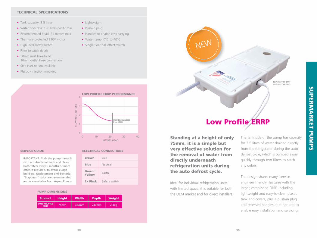
NEW Low Profile ERRPStanding at a height of only 75mm, it is a simple
but very effective solution for the removal of
water from directly underneath refrigeration units
during the auto defrost cycle. Ideal for individual
refrigeration units with limited space, it is suitable for
both the OEM market and for direct installers.
ERRPThe high capacity Economy Retail Refrigeration
Pump tank and covers are plastic, which not
only makes the unit lightweight and easy to clean,
but has allowed the freedom to incorporate extra
features to benefit the service engineer during
installation and maintenance.
Cold CabinetThe stainless steel Cold Cabinet
Refrigeration Pumps high capacity permits
the draining of several units together.
The pump is operated by floats which activate
sensors as the water level rises in the tank. Cleaning
and maintenance of the pump is simple, as they can
be removed easily from underneath any unit.
MaceratorsThe Macerator pumps are designed to
collect condensation and defrost water
from food hall cabinets. They both
feature an internal filter blade to stop
the pump from clogging with food debris
between maintenance visits and will discharge the
water to a head of 8.5 metres.
As environmental concerns grow over
the use of energy within the retail sector,
the use of energy inefficient
evaporator/condensate trays is starting to
raise questions. Aspen’s refrigeration
pumps offer a lower carbon alternative.
The range is designed to work with
integral HT or LT multidecks. The pumps
are suitable for use by both the OEM
market and direct installers.

SU
PER
MA
RK
ET P
UM
PS
A simple yet very effectivesolution for the removal of water from supermarketretail refrigeration units.
The Retail Refrigeration pumps are low
in height which means they can be easily
installed underneath a refrigeration unit,
where direct drainage is not available and
water needs to be pumped up above the
ceiling and away to a suitable drain. The
high capacity of the pumps also permits
the draining of several units together.
The pumps are operated by floats which
activate sensors as the water level rises
in the tank.
Cleaning and maintenance of the
pumps is simple, as they can be
removed easily from underneath
any unit.
37
• Tank capacity: 11 litres
• Water flow rate: 225 litres per hr max
• Recommended head: 35 metres max
• Thermally protected 230V motor
• High level safety switch
• Strainer to catch debris
• 50mm inlet hole to lid10mm outlet hose connection
• Side inlet option available
Economy Retail Refrigeration Pump (ERRP)• Plastic• Lightweight• Push-in plug• Handles to enable easy carrying• Water temp: 0°C to 40°C• Single float hall effect switch
Cold Cabinet• Stainless steel• Hard-wired• Water temp: 0°C to 75°C• 3 floats & relay
TECHNICAL SPECIFICATIONS
Product Height Width Depth Weight
100mm 585mm 400mm 7.8kg
100mm 590mm 405mm 4.9kg
COLD CABINET
ERRP
36
PUMP DIMENSIONS
4
3
2
1
00 10 20 30 40
FLO
W IN
LIT
RES
/MIN
TYPICAL PERFORMANCE
METRES HEAD
Brown Live
Blue Neutral
Green/Yellow
Earth
2x Black Safety switch
ELECTRICAL CONNECTIONS
ERRP
COLD
CABIN
ET
IMPORTANT: Flush the pump throughwith anti-bacterial wash and cleanboth filters every 6 months or moreoften if required, to avoid sludgebuild-up. Replacement anti-bacterial“Stayclean” strips are recommendedand are available from Aspen Pumps.
SERVICE GUIDE
ERRP & Cold Cabinet
TOP INLET FP 2318SIDE INLET FP 2320
TOP INLET FP 2119SIDE INLET FP 2120
SU
PER
MA
RK
ET P
UM
PS
Standing at a height of only75mm, it is a simple butvery effective solution forthe removal of water fromdirectly underneathrefrigeration units duringthe auto defrost cycle.
Ideal for individual refrigeration units
with limited space, it is suitable for both
the OEM market and for direct installers.
The tank side of the pump has capacity
for 3.5 litres of water drained directly
from the refrigerator during the auto
defrost cycle, which is pumped away
quickly through two filters to catch
any debris.
The design shares many ‘service
engineer friendly’ features with the
larger, established ERRP, including
lightweight and easy-to-clean plastic
tank and covers, plus a push-in plug
and recessed handles at either end to
enable easy installation and servicing.
39
• Tank capacity: 3.5 litres
• Water flow rate: 190 litres per hr max
• Recommended head: 21 metres max
• Thermally protected 230V motor
• High level safety switch
• Filter to catch debris
• 50mm inlet hole to lid10mm outlet hose connection
• Side inlet option available
• Plastic - injection moulded
• Lightweight
• Push-in plug
• Handles to enable easy carrying
• Water temp: 0°C to 40°C
• Single float hall effect switch
TECHNICAL SPECIFICATIONS
38
4
3
2
1
00 10 20 30 40
FLO
W IN
LIT
RES
/MIN
LOW PROFILE ERRP PERFORMANCE
METRES HEAD
Brown Live
Blue Neutral
Green/Yellow
Earth
2x Black Safety switch
ELECTRICAL CONNECTIONS
IMPORTANT: Flush the pump throughwith anti-bacterial wash and cleanboth filters every 6 months or moreoften if required, to avoid sludgebuild-up. Replacement anti-bacterial“Stayclean” strips are recommendedand are available from Aspen Pumps.
SERVICE GUIDE
Low Profile ERRP
Product Height Width Depth Weight
75mm 530mm 240mm 2.4kgLOW PROFILEERRP
PUMP DIMENSIONS
NEW
TOP INLET FP 2597SIDE INLET FP 2805
MAX RECOMMEND21m HEAD
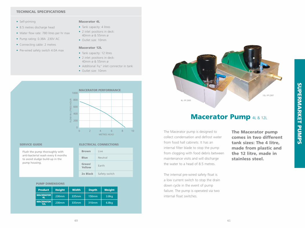
The Macerator pump is designed to
collect condensation and defrost water
from food hall cabinets. It has an
internal filter blade to stop the pump
from clogging with food debris between
maintenance visits and will discharge
the water to a head of 8.5 metres.
The internal pre-wired safety float is
a low current switch to stop the drain
down cycle in the event of pump
failure. The pump is operated via two
internal float switches.
The Macerator pump comes in two different tank sizes: The 4 litre, made from plastic and the 12 litre, made instainless steel.
41
• Self-priming
• 8.5 metres discharge head
• Water flow rate: 780 litres per hr max
• Pump rating: 0.38A 230V AC
• Connecting cable: 2 metres
• Pre-wired safety switch 4.0A max
Macerator 4L
• Tank capacity: 4 litres
• 2 inlet positions in deck: 40mm ø & 55mm ø
• Outlet size: 10mm
Macerator 12L
• Tank capacity: 12 litres
• 2 inlet positions in deck: 40mm ø & 55mm ø
• Additional 3/4” inlet connector in tank
• Outlet size: 10mm
TECHNICAL SPECIFICATIONS
Product Height Width Depth Weight
230mm 335mm 150mm 3.8kg
230mm 335mm 310mm 6.8kg
MACERATOR4L
MACERATOR12L
40
PUMP DIMENSIONS
1000
800
600
400
200
00 2 4 6 8 10
FLO
W IN
LIT
RES
/HO
UR
MACERATOR PERFORMANCE
METRES HEAD
Brown Live
Blue Neutral
Green/Yellow
Earth
2x Black Safety switch
ELECTRICAL CONNECTIONS
Flush the pump thoroughly with anti-bacterial wash every 6 months to avoid sludge build-up in thepump housing.
SERVICE GUIDE
SU
PER
MA
RK
ET P
UM
PS
Macerator Pump 4L & 12L
4L: FP 2305
12L: FP 2307

BEV
ER
AG
E P
UM
PS
43
• Temperature: -20ºC to +90ºC
• Motor options:230V-1Ph-50Hz thermally protected110V-1Ph-60HzOther motors available on request
• Shaft: 316 Stainless steel
• Sealed upper and lower bearings
• Motor IP54 rated (excluding Miniature column pump)
• All pumps supplied with agitator
TECHNICAL SPECIFICATIONS
42
COLUMN PUMP DIMENSIONS
30
25
20
15
10
5
0
21
18
15
12
9
6
3
00 2 4 6 8 10 12 14 16 18 20
HEA
D P
SI
MET
RES
HEA
D
COLUMN PUMP PERFORMANCE
FLOW (LITRES PER MINUTE)
120
173
140
192
185
228
185
228
4 S
TAG
E
1 S
TAG
E
(Mounting plate: 122mm x 149mm)
2 S
TAG
E
3 S
TAG
E
The four Aspen Columnpumps are designedprimarily for beveragechillers, to continuouslypump chilled water arounda python system to providethe optimum cooling rate for soft drinks and cold beverages.
Once the mounting plate is fixed to
the water tank, any of the four
interchangeable pumps can be fitted
by simply twisting the pump so it locks
securely into the bayonet detail on
the plate.
The pumps are just as quick to release
from the plate, without the need to
remove the outlet tube. With minimal
installation costs and low maintenance,
these pumps are ideal for both direct
installers and the replacement market.
Miniature Column PumpFor small chiller and recirculation duties,
this pump offers high
performance and quality
at low cost. The
pump is typically used
in vending machines
but can be adapted to
suit many different markets.
MINIATURE COLUMN PUMP DIMENSIONSAbove fixing surface: 76mm Below fixing surface: 116mm Fixing plate: 136.5mm x 90mm
Brown Live
Blue Neutral
Green/Yellow Earth
2x Black Safety switch
ELECTRICAL CONNECTIONS
MINI
1 STAGE
2 STAGE
3 STAGE
4 STAGE
QUICK TWIST RELEASE
Column Pumps
FP 2866FP 2865
FP 2864FP 2863

PERISTALTICSPARE TUBE KIT
SILICONE GREASE100g
PERISTALTIC ROTOR ASSEMBLY
PERISTALTICFRONT HOUSING &BACK PLATE
PERISTALTICSTANDARDPLUG-IN CABLE
3m PERISTALTICUNIVERSAL PLUG-IN CABLE
PART NO. SA1382
PART NO. FP1282
PERISTALTICPUMP BRACKETFor all Aspen peristaltics
8m PERISTALTICUNIVERSAL PLUG-IN CABLE
TANK PUMPBRACKETFor Hi-flows & Hi-lifts
NON RETURN VALVES(Bag of 5)
1/4” or 3/8”
STRAIGHT CONNECTORS(Bag of 5)
1/4” or 3/8”
REDUCING CONNECTORS(Bag of 5)
1/4” to 3/8”
DRAIN TRAYCONNECTOR(Bag of 5)
16mm with 18,16 &14mm Pipe fitting Ø
INLINE FILTER700 micron mesh
1/4”-1/4” & 3/8”-3/8”
LIME INLET HOSE1 metre length
14mm I/D & 19mm O/D
MINI PUMPFLOAT
PART NO. 1553
PART NO. 1523
1/4” PART NO. 2622 3/8” PART NO. 2624 PART NO. SA1115
PART NO. 2472
PART NO. FP2626
PART NO’s. FRONT HOUSING: 1159 BACK PLATE: SA1161
PART NO. 2457
MINI AQUABRACKET
LIMEBRACKET
PART NO. 1117 PART NO. 1116
PART NO. 2461
PART NO. 1573
PART NO. FP2632 1/4” PART NO. FP2628 3/8” PART NO. FP2630
PART NO. SA2459
1/4” (BAG OF 5) FP2588 3/8” (BAG OF 5) FP25901/4” (50 PIECES) FP2545 3/8” (50 PIECES) FP2646
ANTI BACTERIALTABLET(50 per pack)
18mm Ø
STAY CLEAN STRIP(Bag of 3)
9 x 110 x 25mm
DRAINKLEENONE SHOT(Box of 12)
250ml
VINYL TUBE1/4” x 30m clear or braided3/8” x 30m clear or braided
PART NO’s. CLEAR 1/4”: 1270 BRAIDED 1/4”: 1235CLEAR 3/8”: 1060 BRAIDED 3/8”: 1977
PART NO. 2460
PART NO. FP2418 PART NO. FP1248
4544
PU
MP A
CC
ESSO
RIE
S
SOUND DAMPER(Bag of 5)
4 /6mm
INLINE FILTER (16mm)(Bag of 5)
PUMP TEST BOTTLE500ml capacity
PART NO. 2811
PART NO. FP2858
PART NO. FP2859
COLOURED REDUCERS(Bag of 20)
With 20,18,16 &14mm Pipe fitting Ø
PART NO’s. 16mm: FP2633 18mm: FP2634 20mm: FP2635

REC
LAIM
UN
ITSHighly affordable with nofrills on the outside, it’sextremely efficient on theinside where it matters.
With a 500W oil-less compressor, a large
condenser and high airflow, the
EcoWarrior offers a quick, easy to use
solution for reclaiming refrigerant gases,
which is not only an environmental
necessity but a legal requirement.
Suitable for most types of refrigerant, the
unit has a liquid recovery rate of up to
80kgs/hr, a vapour recovery rate of up to
30kgs/hr, with a purge facility.
Lightweight at under 13kg, the
EcoWarrior has a clear display panel and
a rugged, moulded case with a built-in
carry handle to make your life easier.
47
• Purge facility
• Liquid recovery rate: up to 80kgs/hr
• Vapour recovery rate: up to 30kgs/hr
• Push/pull: up to 320kgs/hr
• 230V & 110V models available
• 500W Oil-less compressor
• High pressure cut out of 410PSIG
• Large condenser and high air flow
• Suitable for most types of refrigerant,both liquid and vapour
• Rugged, moulded case
• Ergonomic carrying handle
• Lightweight at under 13kg
The EcoWarrior is suitable for refrigerants:
R-11, R-12, R-22, R-113, R-114, R-123,
R-134A, R-404, R-407C, R-410A,
R-500, R-502
TECHNICAL SPECIFICATIONS
46
Refrigerant Hoses
• STANDARD HOSE FP 1908
3000 PSI/206 bar burst750 PSI/51 BAR MAX. working pressure
• PREMIUM HOSE FP 1909
4000 PSI/275 bar burst800 PSI/55 BAR MAX. working pressure
Both types of hose are available singly orin packs of 3. They are also available in 3different colours. (Hose length: 72”)
Product Height Width Depth Weight
358mm 395mm 275mm 12.5kgECOWARRIOR
DIMENSIONS
230V FP 2566110V FP 2757
NEW

REC
LAIM
UN
ITSThe lightweight EcoBuddyoffers a highly efficient andeasy to use solution forreclaiming refrigerant gases,which has not only becomean environmental necessity,but a legal requirement.
The EcoBuddy has many features which
make it unique in comparison to other
reclaim units. The adjustable shoulder
strap enables the EcoBuddy to be carried
wherever you want, leaving your hands
free. Integrated into this strap is a shorter
carry strap for easy manoeuvring. The
EcoBuddy is lightweight at under 13kg.
The plug socket on the side of the
EcoBuddy can be used to power a
vacuum pump, electric drill, battery
charger or even your radio!
A tool tray is incorporated at the
front of the EcoBuddy for small fittings
and tools. This releases at the push of
a button and latches securely when
pushed shut.
With its own switch, the light is
invaluable in roof spaces, or on roofs
when nights draw in to help you finish
the job.
49
• Available with or without purge facility
• Liquid recovery rate: up to 80kgs/hr
• Vapour recovery rate: up to 30kgs/hr
• Push/pull: up to 320kgs/hr
• 230V & 110V models available
• 500W compressor
• High pressure output of 410PSIG
• Large condenser and high air flow
• Suitable for most types of refrigerant, both liquid and vapour
• Auxiliary socket
• Includes light and tool drawer
• Rugged, moulded case
• Shoulder strap (easy carry)
• Light weight at under 13kg
The EcoBuddy is suitable for refrigerants:
R-12, R-134a, R-22, R-401A/B/C, R-402A/B,
R-404A, R-407A/B/C/D, R-408A, R-410A,
R-500, R-502, R-507 & R-509
TECHNICAL SPECIFICATIONS
48
Refrigerant Hoses
• STANDARD HOSE FP 1908
3000 PSI/206 bar burst750 PSI/51 BAR MAX. working pressure
• PREMIUM HOSE FP 1909
4000 PSI/275 bar burst800 PSI/55 BAR MAX. working pressure
Both types of hose are available singly orin packs of 3. They are also available in 3different colours. (Hose length: 72”)
Product Height Width Depth Weight
305mm 260mm 430mm 12.7kgECOBUDDY
DIMENSIONS
230V FP 2127110V FP 2125

CO
NTR
OLS
Fan Speed ControllerControls head pressure to air conditioning
and refrigeration systems by increasing
and reducing fan speed with temperature
on the condenser coil. There is also a
heat pump model for connection to the
reversing valve.
3 Phase Failure + PhaseProtection DetectorDesigned to protect 3 phase motors
and industrial equipment from
over-heating due to a phase failure.
When one phase
goes down
motors can seem
to run normally.
It is not until
the motor
overheats that it
is detected, which
may be too late.
Hi-Level Water SensorFor utmost security! The versatile
Hi-Level Water Sensor is available
with two different sensor options:
• Condensate sensor, as used by the
Aspen MK4 peristaltic pump (page 11).
• Float sensor, as used by the Aspen
Mechanical peristaltic pump (page 11).
and Mini Orange pump (page 28-29).
The Hi-Level Water Sensor can be used
in conjunction with most pumps that
do not include high level safety. It also
has 2 levels of sensing - high and low,
both with N.O, N.C & C.
51
Fan Speed Controller
• Available for cooling only• Optional heat pump model• Condenser temperature coil sensor• Max 3 amp output• Minimum speed setpoint 30 to 60°C• Volts: 230V Hertz: 50-60 Hz• Heat pump model: reversing valve input
24 to 240V A.C. opto isolated
3 Phase Failure + Phase Protection Detector
• Input supply 300 to 480V A.C. phase to phase
• Supply frequency 48-63 Hz• Temp range -20 to 60°C• Relay output 8A 250V A.C. resistive
3A 250V A.C. inductive 8A 24V D.C.
Hi-Level Water Sensor
• Volts: 230V Hertz: 50-60 Hz• Two sensor operating systems available:
condensate sensor or float sensor
TECHNICAL SPECIFICATIONS
Product Height Width Depth
83mm 154mm 52mmVFSC
50
DIMENSIONSProduct Height Width Depth
44mm 150mm 75mm
58mm 90mm 35mm
70mm 125mm 90mm
FSC
3 PHASE
HI-LEVEL
DIMENSIONS
These slim, stylish units are designed
for supply/extract ventilation systems.
So many Controllers on the market
are bulky and unattractive, but
this range from Aspen is designed
to be on show... not hidden in
a cupboard!
The controller can easily be
installed either as a flush-fit unit
(recessed) or as a surface mount
unit (retro-fit). The fascia and
enclosure are designed to be slim
and unobtrusive, while the smooth
keypad provides a simple
interface for the end user,
to allow easy control of
their local ventilation.
Ventilation Fan Speed Controller
• 2 & 4 amp models available
• I230V 50Hz fused
• Maximum ambient temperature: 40°C
• IP33 rated
ELECTRICAL SPECIFICATION
COOLING FP 2094HEATING FP 2095
FP 2131
2 AMP FP 23244 AMP FP 2325
FP 2098

bbj contents
designed by engineers for engineers...
The BBJ line of products have been
developed over a number of years
using our extensive knowledge of air
conditioning installations. These are
designed to compliment our extensive
range of pumps. This includes
condensing unit brackets, protective
guards and a complete range of pipe
fixings, all designed to make life easy
and quick for the installation engineer.
We offer full sales and technical support
from our UK based team who will be
pleased to help with any enquiries.
5352
BRACKETS, GUARDS & BLOCKS
54 Type 1 Brackets
54 Type 2 Brackets
56 Non Metal Brackets
56 Quick Fit Brackets
57 Industrial Galvanised Arms
57 Condensing Unit Drip Trays
58 Condensing Unit Blocks
59 Condensing Unit Guards
PIPE CLIPS & HANGERS
60 Insulclamps
61 Metal Hangers
61 Plastic Hangers
62 QPC’s
62 QPH’s
63 Grip Locks
63 Pipe Ties
64 Stud Clip
64 Channel Clip
ISOLATORS & GRAVITY DRAINAGE
65 Isolators
65 Isolator Security Box
65 Condensate Traps
65 Condensate Drain Pipe
TRUNKING
66 Economy Trunking
68 Inoac Trunking
02
70

TYPE 2 BRACKET
TYPE 1 BRACKET
5554
BR
AC
KETS
, GU
AR
DS &
BLO
CK
S
TYPE
2 B
RA
CK
ET
BBJ offer a range of easy to install Condensing UnitBrackets that benefit from a high quality finish. They offer a professionalappearance and highlyeconomic solution forinstallations.
These sturdy and secure Brackets all offer
horizontal flexibility. They are designed for
easy installation and are boxed complete
with all necessary fixings.
All steelwork undergoes a 5-part
phosphating pre-treatment prior to a
60 micron powder coat finish in ivory.
The Type 1 Brackets are designed
to give the choice of 3 positions,
enabling the installation of equipment
in difficult areas.
The self-adjusting
Type 2 Brackets are
designed for quick
installation and easy
levelling on uneven
wall surfaces.
• 4 sizes available: 60, 90, 140 or 250kg maximum load
• 3 mounting positions:low, central & top(Type 1 250kg - single mounting position only)
• 3 sizes available: 60, 90, 140kg maximum load
• Self-adjusting
Product Height Width Depth
450mm - 450mm
500mm - 500mm
550mm - 550mm
680mm - 680mm
60KG
90KG
140KG
250KG
DIMENSIONS
Product Height Width Depth
430mm 720mm 370mm
530mm 900mm 470mm
580mm 1100mm 450mm
60KG
90KG
DIMENSIONS
140KG
Condensing Unit Brackets
PART NO.TYPE 1 60kg B6141TYPE 1 90kg B6142
TYPE 1 140kg B6140TYPE 1 250kg B6584
PART NO.TYPE 2 60kg B6144TYPE 2 90kg B6145
TYPE 2 140kg B6143

INDUSTRIAL GALVANISED ARM
QUICK FIT BRACKET
NON METAL BRACKET
• 2 sizes available: TYPE 1 80kg maximum loadTYPE 2 80kg maximum load
• Ideal for use where thereis salty sea air
• 3 sizes available: 60, 90 or 140kg maximum load
• Levelling system
• Adjustable anti-vibrationrear foot
• Insulating washer and wallfixing kit supplied
5756
• Fits all BBJ Brackets
• Available in 2 sizes
• Choice of metal or plastic
• Flat packed with all required fixings (including 15mm tank connector for outlet)
Product Width Depth Height
800mm 400mm 50mm
1100mm 400mm 50mm
SMALL
LARGE
DIMENSIONS
BR
AC
KETS
, GU
AR
DS &
BLO
CK
S
Product Height Width Depth
410 - 460
410 790 460
TYPE 1
TYPE 2
DIMENSIONS
Product Height Width Depth
130 - 450
130 - 600
SMALL
LARGE
DIMENSIONS
Product Height Width Depth
375mm 800mm 420mm
375mm 800mm 465mm
375mm 800mm 550mm
60KG
90KG
DIMENSIONS
140KG
• 2 sizes available: 450mm (sold as a pair)600mm (sold as a pair)
NEWNEW
Condensing Unit Drip Tray
PART NO.450mm B6859600mm B6860
PART NO.TYPE 1 80kg B6760TYPE 2 80kg B6761
PART NO.TYPE 2 60kg B6861TYPE 2 90kg B6862
TYPE 2 140kg B6863
PART NO.SMALL METAL B6147LARGE METAL B6146
SMALL PLASTIC B6591LARGE PLASTIC B6592
NEW

BBJ CONDENSING UNIT GUARD ASSEMBLY
1 Back frame is provided pre-assembled and should be fixed to the wall through the frame in four places.
2 Push horizontal bars on to fixed back frame.
3 Attach pre-assembled front frame and panel by pushing onto the horizontal bars.
4 Self drilling fixings for side and top panels secure the complete frame.
5 Self-adjusting feet are provided to level the front of the unit or to lift the unit off the ground to allow services at ground level.
58
1
2
3
4
5
59
A range of 3 aestheticallypleasing, unobtrusive BBJCondensing Unit Guards to deter vandalism andprevent damage tovaluable equipment.
The Unit Guard framework is a painted
aluminium structure and the panels are
steelwork, which pass through a 5-part
phosphating pretreatment prior to a 60
micron powder coat finish in ivory.
The Guards are simple and easy to install,
and all panels are removable to allow
maintenance of the unit. A back panel
is available for free-standing units and
extra bottom panels are also available for
Guards fixed at high level on walls.
EXTERNAL DIMENSIONS
Product Height Width Depth
SMALL 700mm 1000mm 450mm
MEDIUM 1100mm 1100mm 600mm
LARGE 1400mm 1100mm 600mm
INTERNAL DIMENSIONS
Product Height Width Depth
SMALL 600mm 900mm 350mm
MEDIUM 1000mm 1000mm 500mm
LARGE 1300mm 1000mm 500mm
PACKING WEIGHTS
Product Weight
SMALL 19kg
MEDIUM 28.5kg
LARGE 34kg
(Units can be supplied
in other colours subject
to requirements)
BBJ Condensing Unit Blocks
• Adapts to all units
• UPVC
• 2 lengths available:SB 450mm length (12 per box) including fixingsSB 1000mm length (2 per box) including fixings
• Maximum load 250 kilos on one point
80mm
70mm
95mm
BR
AC
KETS
, GU
AR
DS &
BLO
CK
S
BBJ Condensing Unit Guard
PART NO.SB 450mm B6658
SB 1000mm B6659
PART NO.SMALL B6192MEDIUM B6191LARGE B6190

PIP
E C
LIPS &
HA
NG
ER
S
BBJ Insulclamps are a well-known range
of pipe clips, supporting individual pipes
in a thermo-rubber cushion between 2
metal parts. Used in the air-conditioning
and refrigeration industry, Insulclamps are
ideal for bigger commercial installations.
The clamps are made of metal and are
therefore safe in the event of a fire
if they are fitted in ceiling voids. The
Insulclamps can be used both internally
and externally.
BBJ Insulclamps provide a simple yet excellentlyengineered solution to the problem of effectivepipe support.
61
• Bagged in 10’s
• A complete range of 14 sizes to fit 1/4” to 41/8” O/D pipes
• Insulates against heat loss and reduces vibration
• Semi-rigid inserts offer good heat resistance
• Plastic inserts designed to withstand temperatures from –25°C to +125°C
• Quick to install with integral lock nuts
• All metal parts are zinc plated andcolour passivated to resist corrosion
• Fits into shallow ceiling void or unit
• Fix to 40 x 40mm and 40 x 20mm channel
• Aluminium channel supplied in either 1 metre (B6000) or 3 metre (B6023) lengths
INSULCLAMP SPECIFICATIONS
60
• Bagged in 10’s
• Quick and easy pipe installation
• Avoids the need for cable trays
• 8 microns colour passivation coating
• Use in areas that are fire sensitive
METAL HANGER SPECIFICATIONS
BBJ 2 BBJ 3 BBJ 4B6492 B6493 B6494
3/8” 1/2” 5/8”
5/8” 7/8” 1 1/8”
LIQUID
GAS
DIMENSIONSApproximate pipe sizes (allowing for insulation)
BBJ Hangers are used to support pipe work hanging from ceilings. They hold both liquid and gas lines.
They fit on both M8 and M10 size studding,
saving time when supporting pipework or
condensate lines. The hangers are adjusted by
simply twisting them up or down the rod. They
need to be installed every 6ft, and using Hangers
means that you no longer need to hang cable trays.
• Bagged in 10’s
• Quick and easy pipe installation
• Avoids the need for cable trays
• Adjustable clipping mechanism
PLASTIC HANGER SPECIFICATIONS
BBJ P2 BBJ P3 BBJ P4B6543 B6544 B6545
3/8” 1/2” 5/8”
5/8” 7/8” 1 1/8”
LIQUID
GAS
DIMENSIONSApproximate pipe sizes (allowing for insulation)
BBJ Plastic Hangers are the idealsolution to support pipework
hanging from ceilings.
This dual stud size clamping system will
fit securely to both M8 and M10 studding.
Three sizes are available, all offering a wide range of
adjustment to fit different insulated pipe diameters.
SIZES AVAILABLE & PART NUMBERS
SIZE PART NO. SIZE PART NO.
1/4” B6268 1 3/8” B6265
3/8” B6274 1 5/8” B6266
1/2” B6267 2 1/8” B6269
5/8” B6276 2 5/8” B6270
3/4” B6273 3 1/8” B6271
7/8” B6277 3 5/8” B6272
1 1/8” B6264 4 1/8” B6275

PIP
E C
LIPS &
HA
NG
ER
S
6362
• Bagged in 10’s
• Hinged for quick and easy pipe installation
• Wide metal components for good pipe support
• Space for electrical cables and condensate tube
• 8 microns of yellow colour passivate
GRIP LOCK SPECIFICATIONS
BBJ Pipe Ties are great for multiplepipework routes. These simple
ties can be fixed easily anddirectly to a wall or channel.
There are 3 sizes of Pipe Tie bases and 6
different lengths of cable ties
to suit various pipe diameters.
Size 1 Size 2 Size 3 Size 4B6186 B6187 B6188 B6189
1/4” 3/8” 1/2” 5/8”
1/2” 5/8” 7/8” 1 1/8”
LIQUID
GAS
DIMENSIONSApproximate pipe sizes (allowing for insulation)
BASE DIMENSIONS
Product Length Width
52mm 45mm
67mm 45mm
79mm 45mm
TIE DIMENSIONS
Product Length Width
200mm 20mm
250mm 20mm
300mm 20mm
350mm 20mm
400mm 20mm
450mm 20mm
• Bagged in 10’s
• A complete range of 9 sizes to fit 1/4” to 15/8” O/D pipes
• Easy installation to 40mm x 20mm channel
• External diameter matches diameter of pipes with 9mm insulation
• Material withstands temperatures from –30°C to +135°C
• Excellent resistance to oil
QPC SPECIFICATIONS
BBJ Grip Locks are particularlygood for installers who, when installing the first pipe, can hold it within theGrip Lock whilst installing the second pipe.
Grip Locks are simple metal pipe clips
that hold both liquid and gas lines.
Designed to be fitted directly to the wall
or solid ceiling, they can hold insulated
pipes without a break in the insulation.
Installation requires only one screw to
be tightened.
BBJ Quick PositioningHangers reduce the numberof stud clips needed to bekept in stock.
This dual stud size clamping system will fit
securely to both M8 and M10 studding.
Five sizes are available to fit a wide range
of different pipe diameters.
QPH’s can support refrigeration pipework,
insulated pipes and condensate lines.
No. 1 No. 2 No. 3 No. 4 No. 5B6532 B6533 B6534 B6535 B6536
1/4” or 3/8” 1/2” or 5/8” 3/4” - 7/8” 1” - 1 1/8” 11/4” - 13/8”
– – – 1/4” - 3/8” 1/2” - 5/8”
– – 20mm 25mm 32mm
COPPER PIPE
INSULATEDCOPPER PIPE
PLASTICCONDENSATE
DIMENSIONS
T200B6410
T250B6411
T300B6412
T350B6413
T400B6414
T450B6415
B1B6407
B1B6408
B1B6409
BBJ Quick Positioning Clipsare a simple pipe clip madefrom a UV resistant plastic.They are fitted intostandard unistrut channelsby just a single twist.
The QPC’s are ideal for smaller installations
and can be used both externally and
internally. They are tidy and give a
professional finish to any installation. The
thickness of the pipe clip is equal to the
wall thickness of the insulation, meaning
no break in “vapour barrier”.
DIMENSIONS
SIZE PART NO. 3/4” B6446
1/4” B6445 7/8” B6449
3/8” B6447 1 1/8” B6442
1/2” B6444 1 3/8” B6443
5/8” B6448 1 5/8” B6538

ISO
LATO
RS &
GR
AV
ITY D
RA
INA
GE
6564
PIP
E C
LIPS &
HA
NG
ER
S
• Bagged in 10’s
• A complete range of 28 sizes to fit 1/4” to 2 1/8” O/D pipes
• Easy installation to M8 andM10 studding
• Fits all types of Metric & Imperial sizing
• Material withstands temperatures from –40°C to +140°C
• Unique lockable ratchet design
STUD CLIP SPECIFICATIONS
• Bagged in 10’s
• A complete range of 14 sizes to fit 1/4” to 2 1/8” O/D pipes
• Easy installation to 41mm channel
• Fits all types of Metric & Imperial sizing
• Material withstands temperatures from –40°C to +140°C
• Unique lockable ratchet design
CHANNEL CLIP SPECIFICATIONS
BBJ Stud and Channel Clipshave a secure and lockablefastening mechanism,allowing quick and easyfixing with the simplefit and twist action.
The unique ratchet design ensures that
the clip remains closed when insulated
pipe is squeezed against the wall of the
clip. The clips are also easy to remove
and relocate for maintenance.
SIZES AVAILABLE & PART NUMBERS
Size M8 M10 41mm
1/4” B6800 B6814 B6842
3/8” B6802 B6816 B6844
1/2” B6801 B6815 B6843
5/8” B6803 B6817 B6845
3/4” B6804 B6818 B6846
7/8” B6805 B6819 B6847
1” B6806 B6820 B6848
1 1/8” B6807 B6821 B6849
1 1/4” B6808 B6822 B6850
1 3/8” B6809 B6823 B6851
1 1/2” B6810 B6824 B6852
1 5/8” B6811 B6825 B6853
2” B6812 B6826 B6854
2 1/8” B6813 B6827 B6855
NEW
CONDENSATE DRAIN PIPE
The sections of PVC pipe contain ‘O’ rings which form a secure waterproof sealbetween fixings when pushed together, with-out the need for gluing. The drain pipe is available in 3 sizes: 20mm, 25mm and 32mm o/d andcomes in 3 metre straight lengths.
• Straight connector
• ‘T’ piece
• 90° connector
• 45° connector
• Wall fixing clip
• 32-25mm reducer
• 25-20mm reducer
MODEL EZT-2263/4” slip fit close-coupled condensateoverflow switchPART NO. FP2465
MODEL EZT-2103/4” condensatetrap with overflow switchPART NO. FP2464
MODEL EZT-150“waterless” 3/4”condensate trapPART NO. FP2463
MODEL EZT-113B3/4” economycondensate trapPART NO. FP2462
BBJ Isolators• IP 65 electrical
isolator for outside use
• 4 types available
Product Height Width Depth
155mm 80mm 100mm
185mm 95mm 110mm
155mm 80mm 100mm
185mm 95mm 110mm
3 pole 25A
3 pole 40A
4 pole 25A
4 pole 40A
Isolator Security BoxTwo part metal housing (270x190x125mm)
to protect an electric isolator with a facility
to utilise a padlock or otherwise.
FIXTURES: (All sold in packs of 20)
PART NO.B6278
PART NO.3 POLE 25A B62793 POLE 40A B62814 POLE 25A B62804 POLE 40A B6660
NEW
NEW
Condensate Traps for air handling units with 3/4” female outlets

EC
ON
OM
Y TR
UN
KIN
G
6766
STRAIGHT DUCT
A
70
105
B
65
75
size (mm)Productcode
D.70
D.105
Overalllength
2000
2000
Qtyboxed
6
6
A
A
B
B
WALLS COVER FOR INLET OR OUTLET
A
110
145
B
180
190
size (mm)Productcode
WC.70
WC.105
C
70.4
105.4
Qtyboxed
20
20
90O ELBOW BEND
A
95
110
B
95
110
size (mm)Productcode
EB.70
EB.105
C
70.4
105.4
Qtyboxed
20
20
WALL ROSETTE
A
115.4
150.4
B
110.4
120.4
size (mm)Productcode
WR.70
WR.105
C
70.4
105.4
Qtyboxed
20
20
FLAT ROSETTE
A
115.4
150.4
B
90
100
size (mm)Productcode
FR.70
FR.105
C
70.4
105.4
Qtyboxed
20
20
FLEXIBLE JOINT
A
500
500
B
65
100
size (mm)Productcode
FJ.70
FJ.105
C
65
100
Qtyboxed
20
20
ELBOW - EXTERNAL 90O
A
95
110
B
95
110
size (mm)Productcode
EIN.70
EIN.105
C
70.4
105.4
Qtyboxed
20
20
DUCT END
A
120
120
B
45
50
size (mm)Productcode
DE.70
DE.105
C
70.4
105.4
Qtyboxed
20
20
90O FLAT BEND
A
115
150
B
115
150
size (mm)Productcode
FB.70
FB.105
C
70.4
105.4
Qtyboxed
20
20
CONNECTION PIECE
A
75.4
110.4
B
70.4
80.4
size (mm)Productcode
CP.70
CP.105
C
70.4
105.4
Qtyboxed
20
20
T-JOINT
A
200
B
105.4
size (mm)Productcode
TJ.105
C
105.4
Qtyboxed
20
45O FLAT BEND
A
92.58
92.58
B
145.5
170.3
size (mm)Productcode
FB.70.45
FB.105.45
C
70.4
105.4
Qtyboxed
20
20
DUCT CAP
A
70
105
B
65
75
size (mm)Productcode
DC.70
DC.105
C
2
2
Qtyboxed
20
20
WALL SLEEVE
A
350
B
100
size (mm)Productcode
ING.341
C
250
D
63
Qtyboxed
20
REDUCER JOINT
A
105.4
B
80.4
size (mm)Productcode
RJ.70.105
C
70.4
Qtyboxed
20
ALSO AVAILABLE:
• DS.70 & DS.105 DUCT STOP
• ADP.93 DRAIN PIPE (50m)
• CET. CLIPS
• CCY. CONNECTORS
A
B
C
A
B
C
A
B
C
B
A
C
A
B
C
A
C
B B
A
C
A
C
B
A
B
C
A
B
C
C
A
B
AB
C
A
B
C
CODE D-70 D-105IVORY B6027 B6026WHITE B6793 B6794
CODE WC-70 WC-105IVORY B6050 B6049WHITE B6789 B6790
CODE EB-70 EB-105IVORY B6035 B6034WHITE B6777 B6778
CODE EIN-70 EIN-105IVORY B6037 B6036WHITE B6779 B6780
CODE WR-70 WR-105IVORY B6053 B6052WHITE B6791 B6792
CODE DE-70 DE-105IVORY B6031 B6030WHITE B6775 B6776
CODE FR-70 FR-105IVORY B6045 B6044WHITE B6785 B6786
CODE FJ-70 FJ-105IVORY B6043 B6042WHITE B6783 B6784
CODE DC-70 DC-105IVORY B6029 B6028WHITE B6773 B6774
CODE RJ-70-105IVORY B6046WHITE B6787
CODE TJ-105IVORY B6048WHITE B6788
CODE CP-70 CP-105IVORY B6025 B6022WHITE B6771 B6772
CODE FB-70 FB-105IVORY B6039 B6038WHITE B6781 B6782
CODE FB-70-45 FB-105-45IVORY B6041 B6040WHITE B6795 B6796
CODE DS-70 DS-105B6033 B6032
CODE ADP-93B6020
CODE CET CLIPB6047
CODE CCYB6021
CODE ING-341IVORY B6051

INO
AC
TRU
NK
ING
6968
STRAIGHT DUCT
A
57.57499138
B
58626878
size (mm)Productcode
CD-60CD-75CD-100CD-140
C
2000200020002000
Qtyboxed
5555
OUTLET COVER
ELBOW (VERTICAL)
END SOCKET
CORNER CAP FLEXIBLE JOINT
WALL CAP
45º ELBOW (VERTICAL)
ELBOW (HORIZONTAL)
SOCKET
T-JOINT 45O ELBOW (HORIZONTAL)
SADDLE BAND
UNIVERSAL ELBOW (HORIZONTAL)
UNIVERSAL ELBOW (VERTICAL)
A
65.582107146
B
65697585
size (mm)Productcode
NC-60NC-75NC-100NC-140
C
120124135149
Qtyboxed
5555
A
65.582107
B
656975
size (mm)Productcode
NU-60NU-75NU-100
C
677283
Qtyboxed
555
A
65.582107
B
656975
size (mm)Productcode
NM-60NM-75NM-100
C
687484
Qtyboxed
555
A
65.582107146
B
65697585
C
200210231286
size (mm)Productcode
NW-60NW-75NW-100NW-140
D
7794119158
E
818396105
Qtyboxed
5555
A
535353
B
303030
C
9999115
size (mm)Productcode
NR-60NR-75NR-100
D
65.582107
E
656975
Qtyboxed
555
A
6784109
B
657076
C
666666
size (mm)Productcode
NA-60NA-75NA-100
D
105124149
E
110125140
Qtyboxed
555
A
110126175
B
110114145
C
161616
size (mm)Productcode
NK-60NK-75NK-100
D
404040
Qtyboxed
555
A
59.576101140
B
60647080
size (mm)Productcode
NF-60NF-75NF-100NF-140
C
60607580
D
5505508001000
Qtyboxed
5555
A
65.586
B
6569
size (mm)Productcode
NZ-60NZ-75
C
117.5122.5
Qtyboxed
55
A
65.582107146
B
65697585
size (mm)Productcode
NE-60NE-75NE-100NE-140
C
119.5141161200
Qtyboxed
5555
A
65.582107146
B
65697585
size (mm)Productcode
NS-60NS-75NS-100NS-140
C
80808080
Qtyboxed
5555
A
65.582107146
B
65697585
size (mm)Productcode
NX-60NX-75NX-100NX-140
C
136.8153
193.5248
Qtyboxed
5555
A
80107146
B
707585
C
120161200
size (mm)Productcode
NT-75NT-100NT-140
D
160215254
E
253535
Qtyboxed
111
360
size (mm)Productcode
NV-L
Qtyboxed
10
CD-60B6000
CD-75B6201
CD-100B6196
CD-140B6199
NW-60B6252
NW-75B6253
NW-100B6248
NW-140B6251
NS-60B6237
NS-75B6238
NS-100B6233
NS-140B6236
NE-60B6214
NE-75B6215
NE-100B6211
NE-140B6213
NX-60B6258
NX-75B6259
NX-100B6255
NX-140B6257
NT-75B6243
NT-100B6240
NT-140B6706
NM-60B6226
NM-75B6227
NM-100B6225
NC-60B6209
NC-75B6210
NC-100B6206
NC-140B6208
NR-60B6230
NR-75B6232
NR-100B6228
NA-60B6205
NA-75B6195
NA-100B6203
NU-60B6245
NU-75B6246
NU-100B6244
NF-60B6219
NF-75B6220
NF-100B6216
NF-140B6218
NK-60B6223
NK-75B6224
NK-100B6221
NZ-60B6261
NZ-75B6262
REDUCER
NJ-60<75B6707
NJ-75<100B6708
NV-LB6247
SMALL SELECTION AVAILABLE IN WHITE: • CD-75 • NE-75 • NW-75 • NA-75 • NS-75 • NC-75
A
69.586
B
6872
C
8080
size (mm)Productcode
NJ-60<75NJ-75<100
D
82107
E
6975
Qtyboxed
55

7170
big foot systems contents
Big Foot Systems are designed to support
anything that is installed on a flat roof.
This creates a safe and secure support for
all air conditioning and refrigeration roof
plant and associated services.
The main advantages of using the Big
Foot System are:–
Reduced risk of leaks
Does not penetrate the roof surface,
removing any difficult detailing
around concrete structures
Reduces the cost of the
roofing installation
Removes concrete obstacles, creating
a clear roof area therefore reducing
complex, timely and expensive
detailing
No plant decommissioning
No need to remove or decommission
roof plant during roof repairs or
resurfacing
Improved aesthetics
Neat and tidy solution for all roof
plant and associated services
72 BIG FOOT BENEFITS
74 BESPOKE FRAMEWORKS
76 MODULAR FRAMEWORKS
78 H FRAME SUPPORT SYSTEM
80 MULTI FOOT SUPPORT SYSTEM
81 FIX-IT FOOT SUPPORT SYSTEM
82 WALKWAY SYSTEMS
83 ACCESSORIES
02
52
The complete solution tosupporting building servicesand access equipment ona flat roof
PIPEWORK
DUCTWORK
CABLE TRAYS
AIR HANDLERS
CONDENSERS
EVAPORATORS
SPLITS
VRV’s & VRF’s
CHILLERS
EXTRACTORS
HEAT PUMPS
SOLAR PANELS
WALKWAYS
STEP OVERS
APPLICATIONS
INST
ALL
ED B
Y S
BH
DES
IGN
& IN
STA
LLA
TIO
N S
ERV
ICES
LTD

BIG
FOO
T SY
STE
MS72
BIG
FOO
T SY
STE
MS
BenefitsSETS THE STANDARD!
48 HOUR DESIGN SERVICE – LET US DO THE WORK
SPREADS THE WEIGHT OF THE SUPPORTED PLANT
EACH FOOT CAN BE REMOVED INDIVIDUALLY TO ALLOW EASY ACCESSTO THE ROOF SURFACE DURING RE-ROOFING OR REFURBISHMENTWITHOUT DECOMMISSIONING EQUIPMENT
NO PENETRATION OF THE WATERPROOF MEMBRANE, ELIMINATING ANYDIFFICULT DETAILING, THEREFORE REDUCING THE RISK OF LEAKS
COST EFFECTIVE
COMPLETE ON-SITE FLEXIBILITY BOTH DURING AND AFTERINSTALLATION
FLATPACK SYSTEM FOR EASY TRANSPORT
HOT DIP GALVANISED METALWORK
ELIMINATES THE RISK TO ROOF GUARANTEE
WALL
RE-ROOFINGThe Big Foot System legs
may be removed
individually for re-roofing/
refurbishment, without
decommissioning or
removing the equipment.
HEIGHT ADJUSTMENTThe legs incorporate
over 100mm of vertical
height adjustment, to
take up variations in the
roof. (300mm: stepped
roof option).
CONDENSER CLAMPSThe repositionable clamps
locate on both sides of
the cross bars, locking
down onto the feet of
the condenser units as
they are tightened.
LINEAR ADJUSTMENT The cross bars which
support the condenser
units can slide along the
plain bars into the position
required, then are locked
securely in place.
LEG & BRACKET POSITIONINGThe leg & bracket are
usually positioned outside
the framework, but can
be positioned inside if
there is an obstruction.
IMPORTANT: The purchaser
or installer of these products
must satisfy themselves that
the roof structure is of
sufficient strength to take the
combined weight of the Big
Foot System and units.
TOTAL LEG HEIGHT: 375mm
(575mm: stepped roof option)
HEIGHT ADJUSTMENT:
245mm – 350mm: floor to framework
(245mm – 550mm: stepped roof option)
Large Stud (440mm)
can be purchased as
an extra individual
component if required.
AV MATS
72 73

74 75
SITE VISIT
48 HRS DESIGN SERVICE
DETAILED PROJECT COSTINGS
ALL WE NEED
IS A PLAN OF
YOUR ROOF,
UNIT WEIGHTS
AND
DIMENSIONS.
WE WILL DO
THE REST!
Tailored to meet your every need.
Using a plan of your roof with dimensions
and weights of the plant, we can specify
complete Big Foot frameworks to support
up to 10 tons. The system is completely
flexible – we can change any part of the
design of the frame at any time! We can
increase or reduce the weight loading
(kN/m2) by changing the size or number
of leg assemblies on the frame.
The Big Foot mouldings are made of Glass
filled Nylon with UV protection. An
independent anti-vibration mat is provided
for each foot. All metalwork is hot dip
galvanised for all weather protection.
Our system allows for each leg assembly
to be removed individually whilst the roof
surface is maintained or even re-roofed
without the need to decommission or
remove the equipment.
Big Foot Systems set the standard of
installation on site, providing the
consultant with a method of installation
which is quick, clean, practical and
aesthetically pleasing.
Bespoke Frameworks
SOLAR PANELS BESPOKE STEPOVER
HSBC LEICESTER DOUBLE STACKED UNITS
BIG
FOO
T SY
STE
MS
Big Foot Systems takes no responsibility for the condition of
the roof on which our equipment is to be used. You must
ensure that the substrate on which the Big Foot is intended
for use is structurally sound enough to take the weight and
point loadings we have indicated.
All Big Foot products must be installed in line with the
guarantees and recommendations of the manufacturer of the
roofing system. The manufacturer of PVC membranes should
advise on the susceptibility migration of plasticizers and
specific recommendations should be adhered to so that the
roof guarantee is not affected.

BIG
FOO
T SY
STE
MS
7776
There are three basic modular frameworks
available in 1m, 2m and 3m versions.
For flexibility, all leg assemblies and
cross bars on the modular frameworks
slide up and down to the required
location (see page 73).
The modular frameworks come with
305mm2 feet which are provided with
anti-vibration mats to fit underneath.
The frame is constructed from 40mm x
40mm standard box section steel.
For heavier loads, larger 450mm2 feet are
available and heavy duty 50mm x 50mm
box section steel for some components.
Modular FrameworksMAX:395mmMIN: 290mm
MIN:290mm
MAX:395mm
1m
2m
MAX: 2.25m
3m
MAX:3.25m
MAX:1.65m1.3m
MAX:1.25m
MAX:1.65m1.3m
MAX:1.65m1.3m
1 METRE SYSTEM FRAMEWORK
2 METRE SYSTEM FRAMEWORK
2 x 1m PLAIN BARS – 40 x 40 SECTION 2 x 1.2m CROSS BARS – 40 x 40 SECTION 4 x LEG ASSEMBLIES WITH AV MATS – 305mm2
2 x CLAMP KITS
WEIG
HT:
42K
GW
EIG
HT:
70K
GW
EIG
HT:
97K
G
SYSTEM COMPONENTS
2 x 2m PLAIN BARS – 40 x 40 SECTION 4 x 1.2m CROSS BARS – 40 x 40 SECTION 6 x LEG ASSEMBLIES WITH AV MATS – 305mm2
4 x CLAMP KITS
SYSTEM COMPONENTS
2 x 3m PLAIN BARS – 40 x 40 SECTION 6 x 1.2m CROSS BARS – 40 x 40 SECTION8 x LEG ASSEMBLIES WITH AV MATS – 305mm2
6 x CLAMP KITS
SYSTEM COMPONENTS
2 Unit System Framework – Part no. B6075
4 Unit System Framework – Part no. B6077
3 METRE SYSTEM FRAMEWORK
6 Unit System Framework – Part no. B6078
MAX:395mmMIN: 290mm

BIG
FOO
T SY
STE
MS
78
The H Frame Set is a quick, versatile and
economical solution for supporting
pipework, ductwork, cable trays or any
combination of these. You provide your
own unistrut, keeping the duct and pipe
installations low cost and totally flexible
by fabricating the frameworks on-site.
Using inserts, the feet adapt to
accommodate 41mm x 41mm off-the-
shelf unistrut. The majority of installations
require 305mm H Frames but where a
greater load spread is required 450mm
H Frames are also available.
SMALL FEET: 305 x 305 x 75mm
LARGE FEET: 450 x 450 x 100mm
On larger, more complex projects,
we are able to offer a pre-fabricated
H Frame design service.
H FrameSupport System
KIT INCLUDES:• 2 x feet • 2 x AV mats • 2 x unistrut inserts • 2 x L-Brackets • 4 x M10 bolts • 4 x square channel nuts
KIT DOES NOT INCLUDE UNISTRUT
H Frame Set 305mm – Part no. B6088H Frame Set 450mm – Part no. B6089
JOH
N L
EWIS
OX
FORD
STR
EET
INST
ALL
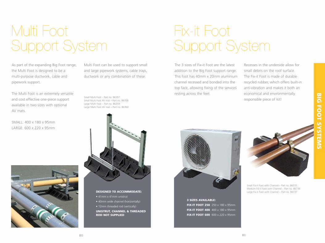
BIG
FOO
T SY
STE
MS
8180
As part of the expanding Big Foot range,
the Multi Foot is designed to be a
multi-purpose ductwork, cable and
pipework support.
The Multi Foot is an extremely versatile
and cost effective one-piece support
available in two sizes with optional
AV mats.
SMALL: 400 x 180 x 95mm
LARGE: 600 x 220 x 95mm
Multi Foot can be used to support small
and large pipework systems, cable trays,
ductwork or any combination of these.
Small Multi Foot – Part no. B6357Small Multi Foot AV mat – Part no. B6358Large Multi Foot – Part no. B6359Large Multi Foot AV mat – Part no. B6360
The 3 sizes of Fix-it Foot are the latest
addition to the Big Foot support range.
This foot has 40mm x 20mm aluminium
channel recessed and bonded into the
top face, allowing fixing of the services
resting across the feet.
Recesses in the underside allow for
small debris on the roof surface.
The Fix-it Foot is made of durable
recycled rubber, which offers built-in
anti-vibration and makes it both an
economical and environmentally
responsible piece of kit!
Multi FootSupport System
Fix-it FootSupport System
DESIGNED TO ACCOMMODATE:
• 41mm x 41mm unistrut
• 40mm wide channel (horizontally)
• 12mm threaded rod (vertically)
UNISTRUT, CHANNEL & THREADEDROD NOT SUPPLIED
3 SIZES AVAILABLE:
FIX-IT FOOT 250 250 x 180 x 95mm
FIX-IT FOOT 400 400 x 180 x 95mm
FIX-IT FOOT 600 600 x 220 x 95mm
Small Fix-it Foot with Channel – Part no. B6735Medium Fix-it Foot with Channel – Part no. B6736Large Fix-it Foot with Channel – Part no. B6737

BIG
FOO
T SY
STE
MS
83
BBJ Walkway Paving BlocksLightweight blocks which protect the roofsurface from damage caused by regular access.600mm x 600mm
BBJ VibromatsThe Vibromats are constructed from milled, sieved and graded Styrene ButadieneRubber. Embedded in two of the Vibromats are metal plates inserted to a depthof 15mm which allow a condenser unit to be screwed directly onto the tile.
500 x 500 x 45mmIdeal for walkways and to protect roof surfaces
600 x 150 x 30mmInserted metal plate
1000 x 500 x 30mm2 Inserted metal plates
1000 x 75 x 15mmMulti purpose
anti vibration strip
Part no. B6496
Part no. B6491 Part no. B6282 Part no. B6024 Part no. B6416
Small Tile Large Tile AV Strip Plain Tile
• QUICK & SIMPLE ASSEMBLY
• EASY TO REMOVE A SECTION FOR ACCESS
• DESIGNED TO SPREAD WEIGHT ON DELICATE ROOF SURFACES
• FLAT PACKED FOR EASY TRANSPORT
• NON-SLIP FIBREGLASS GRATING AVAILABLE IN YELLOW OR GREY
• GALVANISED METALWORK
AA (1.5m) 90º 45ºT-JUNCTION
PQ (1.5m) PQ (1m) OO (1m) OO (0.5m)
1018mm
1388mm
1065
mm
168m
m
103m
m
1m 90º (Corner)
2m Handrail1m Handrail 3m Handrail
2m 3m
82
• RAPID ON SITE FABRICATION –30M PER HOUR
• STRAIGHT LENGTHS IN UP TO3M SECTIONS
• OPTIONAL HAND RAILS CAN BEADDED AFTERWARDS
• RECYCLED RUBBER FOOTSUPPORTS
• AVAILABLE OFF-THE-SHELF
Rapid Walkway SystemThe Big Foot Walkway is ideal for establishing clear, safe pathways around installations
on a flat roof. It offers a secure route for service engineers to gain access to plant and
for managing the flow of other personnel. A brand
new product for the Big Foot Systems range,
this beautifully simple walkway system is
supported on the Fit-it Foot Support System.
Designed to protect and create a designated
walkway area for roof protection, safety
of personnel.
Big Foot Walkway System

Made in Great BritainThis brochure was producedfrom sustainable stock
ASPEN-02/2008
Aspen Pumps /BBJ
Apex Way Hailsham
East Sussex BN27 3WA
T: +44 (0)1323 848842
F: +44 (0)1323 848846
www.aspenpumps.com
Big Foot Systems
Apex Way Hailsham
East Sussex BN27 3WA
T: +44 (0)1323 844355
F: +44 (0)1323 844959
www.bigfootsystems.co.uk


