

1
Push-Pull Messaging: A High-Performance CommunicationMechanism for Commodity SMP Clusters*
Kwan-Po Wong and Cho-Li Wang
Department of Computer Science and Information Systems
The University of Hong Kong
Pokfulam, Hong Kong
[email protected], [email protected]
http://www.srg.csis.hku.hk
Abstract
Push-Pull Messaging is a novel messaging mechanism for high-speed interprocess
communication in a cluster of symmetric multi-processors (SMP) machines. This messaging
mechanism exploits the parallelism in SMP nodes by allowing the execution of
communication stages of a messaging event on different processors to achieve maximum
performance. Some optimizing techniques were implemented along with Push-Pull
Messaging to further improve its performance. Cross-space Zero Buffer provides a unified
buffer management mechanism to achieve a copy-less communication for the data transfer
among processes within a SMP node. Address Translation Overhead Masking removes the
address translation overhead from the critical path in the internode communication. Push-and-
Acknowledge Overlapping overlaps the push and acknowledge phases to hide the
acknowledge latency. Push-Pull Messaging effectively utilizes the system resources. It has
been implemented to support high-speed communication for connecting quad Pentium Pro
SMPs with 100Mbit/s Fast Ethernet.
Keywords: Commodity Cluster, SMP, Communication Protocol, Bandwidth,
Buffer Management, Low-latency communication.
*The research was supported by Hong Kong Research Grants Council grant 10201701 and HKUCRGC grant 10200544. This paper was submitted to ICPP’99 for review on Feb. 8, 1999.
2
IntroductionA cluster refers to a group of whole computers that works cooperatively as a single
system to provide fast and efficient computing services. A commodity cluster integrates
mainstream off-the-shelf components with customized software. Clusters can be classified
into two main categories: Cluster Of Uni-Processor machines (COUP) and Cluster Of Multi-
Processor machines (COMP). A COUP node contains one computation processor, whereas a
COMP node has two or more processors. As the cost of multiprocessor machines decreases,
typically those small-scale SMPs with two to four processors, building a low-cost commodity
COMP is a cost-effective solution to achieve high computing power. However, effective
clustering requires high-performance communication between nodes.
Some representative commodity COUPs are UC Berkeley’s NOW [4], CESDIS’s
Beowulf Project [6], and among others [15]. Recently, COMP has been proven to be a viable
approach to achieve teraflops computing power. IBM’s Blue Pacific [3] and SGI/Cray’s Blue
Mountain [2] are two examples of large-scale COMP. COMPaS developed by RWCP [18],
Clumps by UC Berkeley [14], and FMP by Tsinghua University [16], are the most successful
SMP-type COMPs. All these small-scale COMP used Myrinet as the connection network.
Each Myrinet NIC is equipped with a programmable co-processor (LANai processor) to
enhance the communication performance by moving packet handling and protocol processing
codes from kernel to the NIC [5]. Thus, most implementations can achieve very low point-to-
point communication latency.
Messaging in a distributed environment is non-trivial since the sender and receiver
are not synchronized. The asynchronous nature of message passing leads to additional
overheads in buffering, queuing/de-queuing, and synchronizing communication threads. To
achieve low latency, we should eliminate these overheads from the critical path in
communication. To achieve larger communication bandwidth, efficient coordination between
all communication threads thus maximizing the utilization of the underlying resources is
essential. Building COMPs brings new challenges in designing a high-performance
communication system. In COMP, all processors in a SMP node can process different
3
messages in parallel. Efficient messaging mechanism should minimize the locking effect and
reduce the synchronization overhead while multiple user and kernel processes are accessing
the shared resources and intelligently use any idle or less loaded processor in the SMP node to
handle the messages.
In this paper, we discuss a Push-Pull Messaging and its optimizing techniques to
achieve low latency and high bandwidth communication between processes in the COMP
environment. The concept of Push-Pull Messaging is similar to the classical three-phase
protocol. The messaging process is started by the send party. The send party transmits a
message by first directly “pushing” a portion of the message to the receive party. The receive
party starts the pull phase after the receive operation has been issued and the pushed message
has arrived. The rest of the message is sent after an acknowledgement from the receive party
received by the send party. This communication pattern makes it possible to apply four
optimizing techniques to remove those unexpected overheads from the critical path to achieve
low-latency and high-bandwidth communication. The optimizing techniques include:
• Parallelism Exploitation, which is a technique to allow different execution stages of
both push and pull phases running on different processors to perform protocol
processing concurrently.
• Cross-Space Zero Buffer, which is a unified buffer management mechanism to speed
up the data transfer between process spaces and NIC buffers by eliminating all
unnecessary memory copies.
• Address Translation Overhead Masking, which is an overhead masking technique to
hide the address translation overhead from the critical path by delaying the translation
after communication events.
• Push-and-Acknowledge Overlapping, which is a technique to overlap the push phase
with the acknowledge message to hide the acknowledge latency from the critical path
and further minimize the size of the pushed buffer.
4
With the above optimizing techniques and the use of additional processor in an SMP
node, we can significantly enhance the data communication speed. Our implementation
supports quad Pentium Pro SMP, connected through 100Mbit/s Fast Ethernet. We have
measured the single-trip latency of 34.9 µs, and the peak bandwidth of 12.1 MB/s for the
internode communication. The single-trip latency between processes within the same SMP
node is as low as 7.5 µs and the achievable bandwidth is 350.9 MB/s. We also develop a early
receive and a late receive tests for examining the run-time performance of the proposed
messaging mechanism. It is an low-cost solution to achieve high-speed communication, other
than using expensive interfaces like Myrinet, ATM, or future network interface VIA [20].
For the rest of the paper, we first present the basic idea of Push-Pull Messaging in
Section 1. In Section 2, we discuss the four proposed optimizing techniques. In Section 3, the
performance results are show. Analyses are discussed for both internode and intranode cases.
Finally, the conclusion is given in Section 4.
1 Push-Pull Messaging
Before we start designing the messaging mechanism for SMP clusters, a generic
communication model with four pipelining stages is examined. Related design issues in
COMP are also discussed.
1.1 A Generic Communication Model for SMP
The communication between a pair of COMP nodes can be viewed as a
communication pipeline with multiple process stages. Our Push-Pull Messaging was
developed based on this simple communication model.
• Stage 1: Transmission Thread Invocation. User applications initiate the transmission
by issuing a send operation in user space. Then, the data transmission thread will be
invoked to format outing packets. The thread puts the packets to the outgoing first-in-
first-out (FIFO) queue in the data dump of the network interface card (NIC). In COMP,
several processors may access the NIC simultaneously. To ensure the correctness of the

5
invocation in the multiprocessor environment, the system has to restrict that only one user
or kernel thread invokes the thread at a time. Efficient synchronization between
concurrent processes in the COMP node is critical to the communication performance
[12][19].
• Stage 2: Data Pumping. After the submission of packets, the NIC pumps packets to the
physical network through the hardware on the NIC. The time spent in data pumping
mainly depends on the hardware performance. For example, it can be affected by the
performance of DMA engines in the host node and the NIC, and the network switch
performance [15].
• Stage 3: Reception Handler Invocation. The data arrives the receive party and stores in
a designated buffer in the NIC. Interrupt and polling are two main mechanisms to invoke
the handler to serve the data arrival requests. For COMP nodes, there are two types of
interrupt – asymmetric and symmetric interrupt. With asymmetric interrupt, requests are
always delivered to one pre-assigned processor. With symmetric interrupt [11], requests
can be delivered to different processors, where the selection of processors is governed by
an arbitration scheme. For example, a commonly used scheme selects the least-loaded
processor to serve the interrupt. On the other hand, polling is a light-weight approach to
handle incoming packets. Polling routine watches the change of state variables and starts
the handling routine if necessary. The frequency of polling determines the reliability of
the channel. In COMP nodes, efficient polling mechanisms have been discussed [10][13].
• Stage 4: Reception Processing. After invoking the reception handler, the handler
processes packets immediately. Reception processing involves re-assembly of packets,
copying between buffers, de-queuing buffers and pending requests, and synchronization
between user and kernel threads. In a COMP node, there are multiple active user-level
receiving threads. Without careful coordination between these communication threads
and the reception handler in kernel space, high-speed communication is impossible.

6
1.2 The Main Idea
This section describes the main idea of Push-Pull Messaging based on the
communication model described in Section 1.1. Figure 1 illustrates the communication
architecture of Push-Pull Messaging.
Send Pa r t y
Recep t ion Hand le r
8VHU
6SDFH
.HUQHO
6SDFH
S e n d P r o c e s s
Source Buf fe r
Se
nd
Qu
eu
e
Re
ceiv
e Q
ue
ue
Bu
ffe
r Q
ue
ue
an
dP
ush
ed
Bu
ffe
r
S e n d P r o c e s s
Source Buf fe r
Se
nd
Qu
eu
e
Re
ceiv
e Q
ue
ue
Bu
ffe
r Q
ue
ue
an
dP
ush
ed
Bu
ffe
r
S e n d P r o c e s s
Source Buf fe rS
en
d Q
ue
ue
Re
ceiv
e Q
ue
ue
Bu
ffe
r Q
ue
ue
an
dP
ush
ed
Bu
ffe
r
Inco
min
gF
IFO
buff
erq
ue
ue
Ou
tgo
ing
FIF
Obu
ffer
qu
eu
e
Tex t Space
Da ta Space
Receive Par ty
Recep t ion Hand le r
Rece ive Process
Source Buf fe r
Se
nd
Qu
eu
e
Re
ceiv
e Q
ue
ue
Bu
ffe
r Q
ue
ue
an
dP
ush
ed
Bu
ffe
r
Rece ive Process
Source Buf fe r
Se
nd
Qu
eu
e
Re
ceiv
e Q
ue
ue
Bu
ffe
r Q
ue
ue
an
dP
ush
ed
Bu
ffe
r
Ou
tgo
ing
FIF
Obu
ffer
qu
eu
e
Rece ive Process
Dest inat ion Buf fer
Se
nd
Qu
eu
e
Re
ceiv
e Q
ue
ue
Bu
ffe
r Q
ue
ue
an
dP
ush
ed
Bu
ffe
r
Ne tworkIn
com
ing
FIF
Obu
ffer
qu
eu
eFigure 1. Communication Architecture of Push-Pull Messaging.
As shown in the above figure, each send or receive process has its application-
allocated buffer, source buffer and receive buffer respectively, resided in the user space. Each
process also shares three data structures with the kernel. The send queue stores the
information of pending send operations. The receive queue stores the information of pending
receive operations. The buffer queue and pushed buffer stores pending incoming packets
where their destinations in memory are undetermined.
In Push-Pull Messaging, the send process first pushes a part of the message to the
receive party. The pushed message, which contains BYTES_TO_PUSH bytes, is then handled
by the reception handler in the receive party. Depending on the timing of the receive
operation performed by the receive process, the pushed message will be stored in the pushed
buffer if the receive operation is not started. Otherwise, the message will be copied to the
destination buffer. Once the receive operation started, either the reception handler in the
receive party or the receive process itself will pull the rest of the message from the send
process.

7
The pull phase will be started by sending an acknowledgement, which implicitly
contains request information. The reception handler in the send party processes the
acknowledgement. If the request is granted, the send handler will put the requested part of the
message to the receive party. The reception handler in the receive party handles the message
and directly copies the message to the destination buffer without buffering in the pushed
buffer.
The important parameter BYTES_TO_PUSH defines the number of bytes to be
pushed by the sender at the beginning. This is a balance parameter between the latency of the
network and the latency of the memory system. The method to obtain this parameter is
explained in Section 3.2.
1.3 Two Examples
To clearly understand how the send and receive parties communicate using the push
and pull operations with different timings of the send and receive operations, two examples
are given and the execution flows are shown in Figure 2 and Figure 3. In each figure, the
combined execution flow of the process and the corresponding handler is shown by a vertical
timing lines. Left and right vertical lines represent the execution flow in the send and receive
parties respectively.
In the examples, the send party sends data resided in the application-allocated source
buffer buf to the receive party. The data is transferred over a network link in internode case or
a memory bus in intranode case; then the receive party stores the received data in the
application-allocated destination buffer to_rbuf.
1.3.1 Example 1
In this example, we assume the send process starts the send operation earlier than the
receive process.

8
SendParty
ReceiveParty
Send(buf, len)
pushed message
push( dest_id, buf, BYTES_TO_PUSH,send_queue_no)
CopyBYTES_TO_PUSH
bytes topushed_buf inbuffer_queue
acknowledge( src_id, dst_recv_queue_no,
src_send_queue_no)
buf to_rbufdata transfer
The rest of the message
put( dest_id, the_rest,
len-BYTES_TO_PUSH, dst_recv_queue_no)
Copy (len -BYTES_TO_PUSH) to
to_rbuf
1. Find out physical addresses2. Register receive op
CopyBYTES_TO_PUSHfrom pushed_buf toto_rbuf
Handlemessage
1. Find out physical addresses2. Register send op
Crit icalCommunicat ion
Path
Recv(to_rbuf, len)
Figure 2. Example 1: The send operation starts before the receive operation.
As shown in the above figure, the send process first finds out the associated physical
addresses of buf and registers the information in the send queue. It then directly transfers a
pushed message, which only contains the first BYTES_TO_PUSH bytes of the original
message in buf. When the message arrives, since the receive process has not started the
receive operation, the reception handler has no knowledge where the received data saved in
the process memory space. The message is thus copied to a shared buffer called the pushed
buffer (pushed_buf), which is shared between the receive process and the kernel. The copy
operation is done by the reception handler in the receive party. An entry in the buffer queue in
the receive process is registered. Once the receive process started the receive operation, it
9
finds out the physical addresses of to_rbuf. An entry in the receive queue is registered
immediately.
In the internode case, the receive process then starts the pull operation by sending an
acknowledgement to the send party. The reception handler in the send party processes the
acknowledgement according to the registered information in the send queue. It resumes the
transmission of the message and only transfer the rest of the message. In the receive party, the
receive handler copies the pushed data in pushed_buf to to_rbuf right after it sent the
acknowledgement. After the arrival of the rest of the message, the receive handler copies the
received message directly to to_rbuf. Since the physical address of to_rbuf is available in the
registered information in the receive queue, this data copy operation can be performed
without intermediate buffering.
In the intranode case, the receive process starts the pull operation by simply obtaining
the registered information from the send queue in the kernel. Then, the receive process copies
the rest of the message to to_rbuf using cross-space zero buffer, which is explained in Section
0, without intermediate buffering. No send or receive handlers are involved in this case.
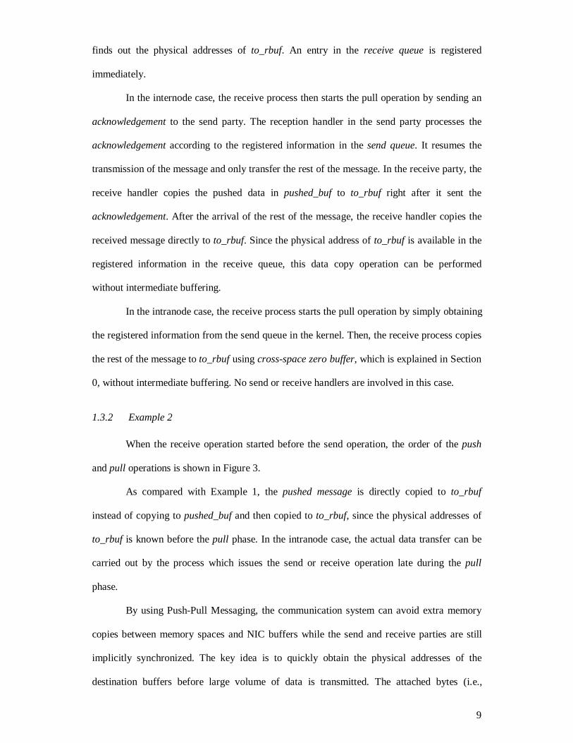
1.3.2 Example 2
When the receive operation started before the send operation, the order of the push
and pull operations is shown in Figure 3.
As compared with Example 1, the pushed message is directly copied to to_rbuf
instead of copying to pushed_buf and then copied to to_rbuf, since the physical addresses of
to_rbuf is known before the pull phase. In the intranode case, the actual data transfer can be
carried out by the process which issues the send or receive operation late during the pull
phase.
By using Push-Pull Messaging, the communication system can avoid extra memory
copies between memory spaces and NIC buffers while the send and receive parties are still
implicitly synchronized. The key idea is to quickly obtain the physical addresses of the
destination buffers before large volume of data is transmitted. The attached bytes (i.e.,

10
BYTES_TO_PUSH) in the pushed message is used to stuff the processing cycles in the
communication pipeline and to efficiently utilize the available network bandwidth and kernel
buffer.
acknowledge( src_id, dst_recv_queue,
src_send_queue_no)
push( dest_id, buf, BYTES_TO_PUSH,sendq_queue_no)
SendParty
ReceiveParty
Send(buf, len)
Recv(to_rbuf, len)
pushed message
buf to_rbufdata transfer
The rest of the message
put( dst_id, the_rest,len - BYTES_TO_PUSH,
dst_recv_queue_no)
Copy (len -BYTES_TO_PUSH) to
to_rbuf
1. Find out physical addresses2. Register receive op
Handlemessage
Handlemessage
CopyBYTES_TO_PUSH to
to_rbuf
1. Find out physical addresses2. Register send op
Crit icalCommunicat ion
Path
Figure 3. Example 2: The receive operation starts before the send operation.
Memory is a valuable resource for improving the communication performance. A
pinned memory area is usually used as communication endpoint in either user or kernel
spaces to improve the communication performance [7][8][18]. This approach could shorten
the critical path in communication by avoiding the delay in handling complicated dynamic
memory management of paging overheads. Although the low-latency communication can be
achieved, inefficient use of these pinned memory areas will limit the communication
11
bandwidth when multiple communication channels are concurrently connected between SMP
nodes. This leads to poor scalability in maintaining high-speed communication in COMP.
To use Push-Pull Messaging, only a buffer of size as small as BYTES_TO_PUSH
bytes is needed as the pushed buffer. However, applications can dynamically specify or
change the size of the pushed buffer to further adapt to the runtime environment.
2 Optimizing Techniques
Push-Pull Messaging discussed previously only avoided expensive copy operations
and optimized the use of the pushed buffer by interchanging push and pull phases. In this
section, we propose several optimization techniques to further shorten the critical path in the
communication.
2.1 Parallelism Exploitation in COMP Nodes
Push-Pull Messaging can further exploit the parallelism in COMP nodes. In a COMP
nodes, push and pull phases can be carried on different processors to produce maximum
performance. Some systems, such as Intel Paragon, used the second processor as a
communication processor to offload the message processing overhead. In our design, we used
different approach.
After the push phase, the rest of the message will be transfer by the pull operation. As
the pull phase is designed to make a direct transfer from the source buffer to the destination
buffer without intermediate buffering, this phase can be handled by a lightly loaded processor.
It is not necessary to be handled by the same processor as the one used in applications. The
selection of the processor depends on the reception handler invocation method. In all tests, we
used symmetric interrupt mechanism in our optimized Push-Pull Messaging. The mechanism
allows the pull phase to be executed on a least-loaded processor. Because of running the pull
phase on another processor, the phase can be overlapped with the computation or
communication events carrying on other processors. This overlapping can hide portion of the
communication latency in the internode test. The hiding mechanisms are discussed in Section
2.3 and 2.4.

12
In the push phase, we did in the reverse way. We did not choose the lightly loaded
processor. This is because offloading the processing overhead to other processors could not
exploit the temporal cache locality in the original processor. Contrarily, it may introduce a
large number of cache misses. Instead of offloading, we execute the push phase on the
processor same as the one serving the send process.
2.2 Cross-Space Zero Buffer
Cross-Space Zero Buffer is a technique to improve the performance of data copying
across different protected process space and kernel spaces. In a message passing program, the
syntax of the communication commands is usually defined as follows.
send(source_buffer_address, buffer_length)
receive(destination_buffer_address, buffer_length)
The send operation accepts a virtual address of the source buffer and its length. Like
the send operation, the receive operation requires two input arguments, the virtual address of
the receive buffer and the buffer size. Both buffers are allocated by applications in the user
space. As user process spaces are protected, direct communication cannot be carried out
between two user processes. Typically, the communication is taken place through a shared
memory facility provided by the kernel. Using shared memory approach, however, introduces
an unavoidable memory copy operation. For example, the send process needs to copy the
source buffer to the intermediate shared buffer, while the receive process reads data from the
shared buffer and copies it to the destination buffer. The unavoidable copy operation results in
extra memory copy overheads, thus lengthening the communication latency and consuming
more memory resource.
We attacked the problem by employing a cross-space zero buffer technique. This
technique realizes one-copy data transfer across process spaces, thus increasing the bandwidth
of the intranode communication. To realize the one-copy transfer across process spaces,
physical addresses of source and destination buffers are needed. Although the virtual
addresses of buffers are continuous, the corresponding physical addresses may be
13
discontinued across pages. Since buffers may not reside in contiguous memory space, pairs of
physical address and length need to be obtained before the actual data movement. The
physical address points to the starting address of the multiple buffer pages. The length
denotes the number of contiguous bytes at the corresponding address. Since this data structure
only contains addresses and length values but not the actual messages, we call it zero buffer.
By knowing the physical addresses of both buffers, data transfer from the source buffer to the
destination buffer can be performed by a kernel thread. Therefore, one-copy data transfer
across different process spaces could be achieved.
In Push-Pull Messaging, zero buffers are implemented to improve the performance of
intranode communication between user process spaces. The buffer is also implemented to
allow direct transfer of data from the NIC designated buffer to the destination buffer in
internode communication. The data transfer is initiated once the physical addresses of buffers
are known.
2.3 Address Translation Overhead Masking
Address translation overhead masking is a technique to hide the address translation
overhead in the internode communication. With implemented zero buffer, the data transfer
from the NIC buffer to the destination buffer on the same machine can be carried out directly
by the kernel without the involvement of the process. However, Push-Pull Messaging needs to
perform address translation before using zero buffers.
The address translation overhead grows linearly as the size of the message increases.
Since the communication event requires relatively long latency time to complete than the
address translation, we can schedule every network communication event in the push and pull
phases before the address translation to mask the overhead. However, not all translations can
be safely delayed. The translation of the pushed message needs to be done before initiating
the first network transmission.

14
SendParty
ReceiveParty
Recv(to_rbuf, len)
first-pushed message
push
acknowledge
buf to_rbufdata transfer
The rest of the message
put
1. Find out physicaladdresses2. Register receiveop
Handle request
Handle message 1
1. Find out physicaladdresses
2. Register send op
second-pushed message
Send(buf, len)
CopyBYTES_TO_PUSH(1)
to to_rbuf
CopyBYTES_TO_PUSH(2)
to to_rbuf
Handle message 2
Handle message 2Copy ( len -
BYTES_TO_PUSH (1 ) -BYTES_TO_PUSH(2 ) ) t o
to_rbuf
Send/RecvThread in
NIC
Send/RecvThread in
NIC
ExecutionThread in
processors
ExecutionThread in
processors
ControlTransfer
CriticalCommunication
Path
Figure 4. Overhead Masking and Push-and-Acknowledge Overlapping are used in Push-Pull Messaging. The receive operation starts before the send operation.
To further hide this translation overhead, the copy of the pushed message to the NIC
outgoing buffer has to be performed in user space. This can be done by direct thread
invocation method. The direct thread invocation method is a method to invoke the
transmission thread in the NIC at the user level without using system calls. This method is
achieved by mapping NIC control registers and buffers onto the user process space. Thus, the
send process can directly trigger the NIC to start the send operation. Similar approaches can
be found in DP [14], GAMMA [7] and U-Net [8].
Since all address translations can be safely delayed, the translation overhead is moved
away from the critical path in communication. Figure 4 illustrates this masking technique.

15
The address translation, which is shown as “Find out physical addresses”, is delayed in the
send and receive parties as compared with Figure 2 and Figure 3.
2.4 Push-and-Acknowledge Overlapping
Push-and-Acknowledge is an optimizing technique to hide the acknowledge latency in
the internode case. Originally in Push-Pull Messaging, sending the acknowledge message is
on the critical as shown in Figure 2 and Figure 3. To further enhance the performance of
Push-Pull Messaging, we overlap the push and acknowledge phases in order to hide the long
acknowledge latency. This optimization is also shown in Figure 4.
The pushed BYTES_TO_PUSH bytes, originally used in Push-Pull Messaging, are
split into two parts. The first part, the first-pushed message of BYTES_TO_PUSH(1) bytes, is
pushed to the destination at the beginning. Transmission of the second part, the second-
pushed message of BYTES_TO_PUSH(2) bytes, is overlapped with the transmission of the
acknowledge message. The latency of the request message is masked. Push-and-Acknowledge
Overlapping further minimized the size of the pushed buffer. Only the maximum of the two
values, BYTES_TO_PUSH(1) and BYTES_TO_PUSH(2) is used as the size of the buffer.
3 Performance Results and Analysis
The proposed Push-Pull Messaging was implemented and evaluated on two ALR
Revolution 6X6 Intel MP1.4-complaint SMP computers. Each computer consisted of four
Intel Pentium Pro 200 MHz processors with 256 Mbytes of main memory. Each Intel
processor had 8-Kbyte L1 instruction cache and 8-Kbyte data caches. The size of the unified
L2 cache is 512 Kbytes. The computers were connected by Fast Ethernet with the peak
bandwidth of 100 Mbit/s. Each computer attached one D-Link Fast Ethernet 500TX card with
Digital 21140 controller. Linux 2.1.90 was installed on each machine with symmetric
interrupt enabled.
We evaluated the performance of intranode and internode communication. In each
case, the single-trip latency of the communication system with different values of the
parameter BYTES_TO_PUSH was measured. In all benchmark routines, source and
16
destination buffers were page-aligned for steady performance. The benchmark routines used
hardware time-stamp counters in the Intel processor, with resolution within 100 ns, to time
the operations. Each test performed one thousand iterations. Among all timing results, the
first and last 10% (in terms of execution time) were neglected. Only the middle 80% of the
timings was used to calculate the average.
The round-trip latency test measured the ping-pong time of two communicating
processes. The bandwidth test measured the time to send the specified number of bytes from
one process to another process, plus the time for the receive process to send back a 4-bytes
acknowledgement. The time measured was then subtracted the single-trip latency time for a 4-
byte message. Thus, the bandwidth was calculated as the number of bytes transferred in the
test divided by the calculated time.
3.1 Intranode Performance Test
0
20
40
60
80
100
120
10 1000 3000 4000 5000 8192Size (Bytes)
Sin
gle-
Trip
Mea
n La
tenc
y (u
s)
push-zero
push-pull
push-all
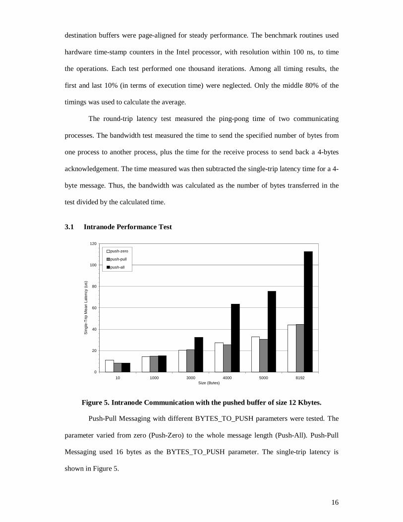
Figure 5. Intranode Communication with the pushed buffer of size 12 Kbytes.
Push-Pull Messaging with different BYTES_TO_PUSH parameters were tested. The
parameter varied from zero (Push-Zero) to the whole message length (Push-All). Push-Pull
Messaging used 16 bytes as the BYTES_TO_PUSH parameter. The single-trip latency is
shown in Figure 5.

17
In the intranode communication, when the size of the message was below 16 bytes,
Push-Pull and Push-All Messaging performed equally well and both outperformed Push-Zero
Messaging. In this case, both send and receive operations were equally “light”. The receive
operation could not complete the registration of the operation before the send operation
started the actual data transfer. Therefore, Push-Pull and Push-All needed to utilize the pushed
buffer for the transfer. However, copying the message twice between the buffers only costs a
small amount of overhead, as the message was so small. Push-Zero Messaging tried to avoid
copying twice by synchronizing the send and receive parties. However, the synchronization
cost a larger amount of overhead.
From 10 bytes to 3000 bytes, the receive operation could register the destination
buffer information before the send operation started the actual data transfer. All mechanisms
could proceed without using the pushed buffer, including Push-All for most of the cases. They
all used zero buffers to minimize the transfer overhead. For messages shorter than 16 bytes,
Push-Pull operated like Push-Zero. For messages larger than 16 bytes, Push-Pull returned to
its standard operation. This change in communication pattern allowed Push-Pull to effectively
reduce the number of memory copies in the pull phase. Push-Zero also synchronized the send
and receive parties before transferring the message. This synchronization and the change in
pattern allowed both messaging mechanisms utilizing their zero buffers. Therefore both
messaging mechanisms outperformed Push-All.
Around 4000 bytes, the latency of Push-All Messaging was abruptly increased but
Push-Pull and Push-Zero kept increasing steadily. The cause of this sudden performance lost
was the timing of the send and receive operations. Originally, the receive operation could
register the destination buffer information before the actual data transfer. However, the
address translation overhead grows with the message size. As the receive operation became
“heavier”, Push-All could not always proceed without using the pushed buffer. The
registration could not be completed before the actual transfer in most of the times.
Consequently, the data transfer involved the pushed buffer and could not exploit the zero
18
buffer. The average performance was further degraded around 3000 to 4000 bytes. Push-All
performed poorer than Push-Pull and Push-Zero for most of the message sizes.
Zero buffer played an important role in minimizing the latency in all messaging
mechanism. However, to truly exploit the mechanism, a proper communication pattern should
be adopted. Since the communication pattern of Push-Pull and Push-All reinforced the
execution order of the registration and data transfer phases, the performance of zero buffer
could be exploited effectively. The buffer not only shortened the latency of the messaging, but
it also improved the bandwidth of the communication since only one memory copy is needed.
The measured peak bandwidth of Push-Pull is 350.9 Mbytes/s when sending around 4000
bytes, almost 66% of the theoretical 533-Mbyte bus bandwidth. The minimum latency for
sending a 10-byte message is only 7.5 µs.
3.2 Internode Performance Test
We carried out three latency tests to evaluate the effectiveness of Push-Pull
Messaging in the internode communication. Symmetric interrupt was chosen as the reception
handler invocation method in all tests.
We used 80 bytes and 680 bytes as the value of BYTES_TO_PUSH(1) and
BYTES_TO_PUSH(2) respectively. These parameters were obtained independently by two
separate tests.
The first test measured the latency by varying the value of BYTES_TO_PUSH(2) but
let BYTES_TO_PUSH(1) be zero. This test only exploited the Push-and-Acknowledge
Overlapping technique. As the value of BYTES_TO_PUSH(2) increased, the latency of a
longer and longer second-pushed message could be hidden effectively. Thus, the remaining
bytes of the message to be pushed could be shorter and shorter. Since the pulled message was
on the critical path in communication, the overall latency could be shortened as the value of
BYTES_TO_PUSH(2) increased. However, there was an upper limit on the
BYTES_TO_PUSH(2) value since the latency of the overlapped acknowledge phase was
about the single-trip time of a short message. If the value of BYTES_TO_PUSH(2) was too

19
large, the overall latency would increase as the reception handler was unable to serve the
second-pushed message and the pulled message in parallel. In this test, we obtained 680 bytes
as the value of BYTES_TO_PUSH(2).
In the second test, we fixed 680 bytes as the value of BYTES_TO_PUSH(2) and
varied the value of BYTES_TO_PUSH(1). We then measured the overall latency. As the
first-pushed message was on the critical path as shown in Figure 4, the latency grew with the
value of BYTES_TO_PUSH(1) when the BYTES_TO_PUSH(1) value was larger than a
threshold value. However, when the value was smaller than the threshold value, the latency
would actually decrease. This reduction is caused by filling the time gap between serving the
first and the second pushed message, which is illustrated as “Handle message 1” in Figure 4.
As the time to handle the message was a little bit faster than the time to initiate the
transmission of the second-pushed message, the receive party would have more time to
process the first-pushed message. Therefore sending a longer first-pushed message would
save some bandwidth, thus shortening the overall latency. In this test, we obtained 80 bytes as
the value of BYTES_TO_PUSH(1).
3.2.1 Optimizing Test
0
50
100
150
200
250
0 200 400 600 800 1000 1200 1400Size (Bytes)
Mea
n La
tenc
y (u
s)
no optimization
mask only
overlap only
full optimization
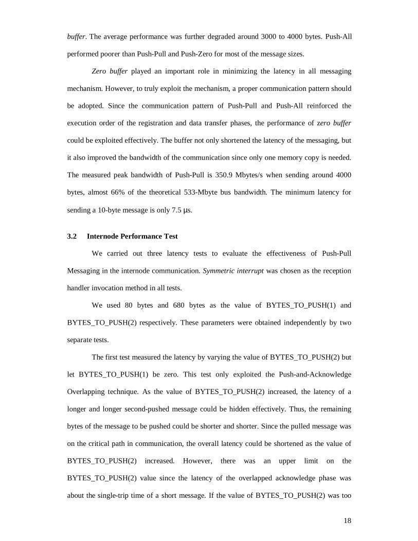
Figure 6. Performance measurement of the internode communication using threeoptimizing techniques.

20
In the first latency test, we compared the raw performance of Push-Pull Messaging
with three optimized Push-Pull Messaging – Address Translation Overhead Masking
(represented by [∆]), Push-and-Request Overlapping (represented by [×]) and their combined
version (represented by [�]).
Before 760 bytes, all four messaging mechanisms behaved the same since the whole
message was pushed to the receive party directly. After 760 bytes, the messaging mechanisms
with Address Translation Overhead Masking and Push-and-Acknowledge Overlapping
efficiently masked the overheads at both send and receive parties. Therefore, both techniques
showed significant improvement over the non-optimized messaging mechanism. When we
compared these two techniques, Push-and-Acknowledge Overlapping showed larger
improvement. It is because the acknowledge latency, which is hidden by Push-and-
Acknowledge Overlapping, is larger than the translation overhead saved in Address
Translation Overhead Masking. In the figure, the full optimization showed the most
promising solution, which integrated both orthogonal techniques.
3.2.2 Early and Late Receiver Tests
ping(){ barrier (); start = get_timer(); compute x times; pp_send(message); compute y times; pp_receive(message); latency = get_timer() – start;}
pong(){ barrier (); compute y times; pp_receive(message); compute x times; pp_send(message);}
Figure 7. Ping-Pong Benchmark Pseudo Codes.
In a distributed environment, the sender and receiver operate in an asynchronous
manner. Extra blocking time happens when the receive party starts earlier than the send party;
while overheads are always caused by the late start of the receive process as discussed in the
Introduction section. When we measured the latency of the internode communication, the
ping-pong benchmark routine was redesigned to simulate a typical compute-then-
communicate parallel program to examine the runtime performance of Push-Pull Messaging.

21
As shown in Figure 7, the ping and pong procedures compute before communicates. Before
taking the measurements, we further synchronized both parties with a barrier operation, which
was a simple ping-pong operation.
In the test, we varied both computations by inserting different number of NOP (No
Operation) instructions. Two variations were tested. In the early receiver test (denoted by the
word “early” in Figure 8 left), we forced the receive operation started before the send
operation. The value of x and y were chosen to be 500,000 and 100,000 respectively. The
other one is called late receiver test (denoted by the word “late” in Figure 8 right). In this test,
we forced the receive operation always started after the send operation. The value of x and y
were chosen to be 100,000 and 300,000 in this test. In other words, we forced all messing
mechanisms utilizing the pushed buffer. The number of NOPs was pre-computed with the
consideration of the barrier synchronization delay since the ping process always late about a
single-trip latency time spent in waiting the implicit synchronization message from the pong
process. We carried out the tests for the three messaging mechanisms, namely Push-Zero,
Push-Pull and Push-All, with full optimization.
3 50 0
3 70 0
3 90 0
4 10 0
4 30 0
4 50 0
4 70 0
4 1 02 4 2 04 8 3 07 2 4 09 6 5 12 0 6 14 4 7 16 8 8 19 2S ize (B yte s )
Single
-TripM
eanL
atency
(us)
p ush-zero/e ar ly
p ush-p ull /e ar ly
p ush-a ll/ea r ly
8 00
1 00 0
1 20 0
1 40 0
1 60 0
1 80 0
2 00 0
4 1 02 4 2 04 8 3 07 2 4 09 6 5 12 0 6 14 4 7 16 8 8 19 2S ize (B yte s )
Single
-TripM
eanL
atency
(us)
p ush-zero/la te
p ush-p ull /l ate
p ush-a ll/ la te1 49 40 0
1 49 60 0
Figure 8. Performance Comparison of Push-Pull Messaging for early and late receivetests with the pushed buffer of size 4 Kbytes.

22
For the early receiver test, since the receive operation always finished before the send
operation, the address of the destination buffer was already known to the reception handler at
the receive party before issuing the send operation. Therefore, the reception handlers in all
three messaging mechanisms could copy the received data directly to the destination buffer
using zero buffers without intermediate buffering. Thus, the size of the pushed buffer did not
significantly affect the performance for all message lengths.
However, because of the difference in the communication pattern, Push-Pull and
Push-All always outperformed Push-Zero. It is because the push phase in Push-Zero was not
used to perform any useful transfer of data. This phase was originally used to preserve the
execution order of the registration of the pending receive operation and the pull
communication. This order, however, was already reinforced due to the lightly loaded
receiver and the heavily loaded sender. Therefore, the push phase in Push-Zero was wasting
the communication bandwidth. As the network latency was long as compared with the bus
latency in the intranode communication, Push-Zero was constantly slowed down.
Push-Pull outperformed Push-All in most cases in the early receiver test because the
address translation overhead was effectively hidden. Push-All could not hide the overhead as
the communication pattern did not allow doing so. The improvement of Push-Pull over Push-
All, however, was not significant because the translation overhead was not large and the
number of memory copies in both mechanisms was the same. During the push phase, Push-
All could bypass the intermediate buffer as the receive operation was completed like Push-
Pull. Therefore, the performance of Push-All was similar to the performance of Push-Pull.
For the late receiver test, as the computation on the receive party was on the critical
measurement path, the computation contributed part of the latency. In this test, the
transmission of the pushed messages, if any, were always pushed to the pushed buffer. Since
the receive operation was initiated so late, the reception handler in the receive party could not
process the remaining part of the message without intermediate buffering in the pushed buffer.
Therefore, the handler had to copy the message one more time before copying to the
destination.

23
Before 3072 bytes, Push-All performed more satisfactory than Push-Pull and Push-
Zero because whenever the receive operation was started, the pushed buffer contained the
whole message. The message could then be copied directly to the destination buffer by the
receive process. However in Push-Pull and Push-Zero, the receive operation always needed to
initiate the transmission of an acknowledgement. Therefore, Push-Zero performed poorly for
all message sizes whereas Push-Pull introduced long network latency time after around 800
bytes. Although Push-All delivered messages faster than others did, the performance was
degraded significantly after around 3000 bytes. This degradation showed that the pushed
buffer in Push-All was overwhelmed by incoming packets. Most of the packets were lost
during the communication. With the implemented go-back-n reliable protocol [17], Push-All
could resume the transmission afterwards but it still could not outperform others. It took
around 150 ms to transfer a 3072-byte message while Push-Zero took 1303.58 µs and Push-
Pull even took only 1227.42 µs.
On the other hand, Push-Pull always outperformed Push-Zero in this late receive test.
The reason is that Push-Pull had sent BYTES_TO_PUSH bytes to the receive party during the
push phase. Therefore during the pull phase, shorter message was delivered.
Push-Pull Messaging showed very steady performance in all cases as compared with
Push-All and Push-Zero. Push-Pull Messaging could flexibly adapt to cluster environment
with different computation load and maximize the performance. We have measured the peak
bandwidth of the fully optimized Push-Pull Messaging. The peak bandwidth could be as high
as 12.1 Mbytes/s. The shortest single-trip latency was 34.9 µs.
4 Conclusion
Building COMPs brings new challenges in designing a high-performance
communication system. Our communication system is able to achieve very low-latency and
high-bandwidth interprocess communication in COMP. Cross-Space Zero Buffer provides a
unified buffer management mechanism to achieve a copy-less communication for the data
transfer among processes within a SMP node. This mechanism efficiently eliminates all

24
unnecessary memory copy operations in the intranode communication, where a peak
bandwidth of 350.9 MB/s is achieved. Address Translation Overhead Masking hides the
address translation overhead, around 12-13 µs for long messages, from the critical path in the
internode communication. The Push-and-Acknowledge Overlapping overlaps the push and
acknowledge phases to hide the acknowledge latency from the critical path. Among these
optimizing techniques, Push-and-Acknowledge Overlapping can reduce most of the overheads
in the internode communication, while Cross-Space Zero Buffer can significantly improve the
communication bandwidth in the intranode communication. Although several complex
optimizations were provided, the porting of high-level languages was still very easy.
Currently, the bandwidth of Fast Ethernet is still low compared with the peripheral
bus bandwidth. We believe the next important step is to design a more general mechanism to
work with multiple network interfaces using multiple processors. We also plan to implement
Push-Pull Messaging in Gigabit Ethernet to exploit the power of the SMP node.
5 References
[1] R. H. Arpaci-Dusseau, A. C. Arpaci-Dusseau, D. E. Culler, J. M. Hellerstein, D. A.Patterson. “The Architectural Costs of Streaming I/O: A Comparison of Workstations,Clusters, and SMPs”, Proc. of the 4th International Symposium on High-PerformanceComputer Architecture (HPCA-4), 1998.
[2] ASCI Blue Mountain, http://www.lanl.gov/Internal/projects/asci/bluemtn, December,1997.
[3] ASCI Blue Pacific home page, http://www.llnl.gov/asci/platforms/bluepac, December,1997.
[4] T. E. Anderson, D. E. Culler, D. A. Patterson, and the NOW team. “A Case for NOW(Networks of Workstations)”, IEEE Micro, 15(1), February, 1995.
[5] N. J. Boden, D. Cohen, R. E. Felderman, A. E. Kulawik, C. L. Seitz, J. N. Seizovic, W.K. Su. “Myrinet: A Gigabit-per-Second Local Area Network”, IEEE Micro, 15(1):29-36, February, 1995.
[6] D. J. Becker, T. Sterling, D. Savarese, J. E. Dorband, U. A. Ranawak and C. V. Packer.“Beowulf: A Parallel Workstation for Scientific Computation”, Proc. of InternationalConference on Parallel Processing, 1995.
[7] G. Ciaccio. “Optimal Communication Performance on Fast Ethernet with GAMMA”,Proc. of International Workshop on Personal Computers based Networks OfWorkstations 1998 (PC-NOW '98), Orlando, March 30/April 3, 1998.

25
[8] T. von Eicken, A. Basu, V. Buch and W. Vogels. “U-Net: A User-Level NetworkInterface for Parallel and Distributed Computing”, Proc. of the 15th ACM Symposiumon Operating Systems Principles (SOSP’95), December, 1995.
[9] T. von Eicken, D. E. Culler, S C. Goldstein and K. E. Schauser. “Active Messages: AMechanism for Integrated Communication and Computation”, Proc. of the 19th AnnualInternational Symposium on Computer Architecture (ISCA ’92), May, 1992.
[10] B. Falsafi and D. A. Wood. “Scheduling Communication on an SMP Node ParallelMachine”, Proc. of the 3rd International Symposium on High-Performance ComputerArchitecture (HPCA-3), 1997.
[11] “Intel Architecture Software Developer’s Manual Volume 3: System ProgrammingGuide”, Intel Corporation.
[12] S. S. Lumetta and D. E. Culler. “Managing Concurrent Access for Shared MemoryActive Messages”, Proc. of the 12th International Parallel Processing Symposium(IPPS ’98), 1998.
[13] B. H. Lim, P. Heidelberger, P. Pattnaik and M. Snir. “Message Proxies for Efficient,Protected Communication on SMP Clusters”, Proc. of the 3rd International Symposiumon High-Performance Computer Architecture (HPCA-3), 1997.
[14] S. S. Lumetta, A. M. Mainwaring and D. E. Culler. "Multi-Protocol Active Messageson a Cluster of SMP's", Proc. of Supercomputing '97 High Performance Networkingand Computing (SC97), November, 1997.
[15] C. M. Lee, A. Tam, and C. L. Wang, “Directed Point: An Efficient CommunicationSubsystem for Cluster Computing”, Proc. of the 10th International Conference onParallel and Distributed Computing and Systems (IASTED ’98), Las Vegas, 1998.
[16] J. Shen, J. Wang and W. Zheng. “A New Fast Message Passing CommunicationSystem for Multiprocessor Workstation Clusters”, Technical Report, Department ofComputer Science and Technology, Tsinghua University, China, 1998.
[17] A. S. Tanenbaum. “Computer Networks”, 3rd Edition, Prentice-Hall International, Inc.,1996.
[18] Y. Tanaka, M. Matsua, M. Ando, K. Kubota and M. Sato. “COMPaS: A Pentium ProPC-based SMP Cluster and its Experience”, Proc. of International Workshop onPersonal Computers based Networks Of Workstations 1998 (PC-NOW '98), Orlando,March 30/April 3, 1998.
[19] R. C. Unrau, O. Krieger, B. Gamsa and M. Stumm. “Experiences with Locking in aNUMA Multiprocessor Operating System Kernel”, Proc. of Operating Systems Designand Implementation (OSDI ’94), 1994.
[20] “Virtual Interface Architecture Specification. Version 1.0”, Compaq, Intel andMicrosoft Corporations, December 16, 1997, http://www.viarch.org/ andhttp://www.giganet.com/.


