

MAKING MODERN LIVING POSSIBLE
Technical Information
Electrohydraulic ActuatorsPVE, Series 4 and PVHC
powersolutions.danfoss.com
Revision history Table of revisions
Date Changed Rev
February 2015 Oil consumption corrected GE
January 2014 Converted to Danfoss layout – DITA CMS GD
March 2013 Back page matter change GC
August 2012 Various changes, new articles about NP GB
May 2012 Major update GA
Technical Information PVE, Series 4 for PVG 32/100/120 and PVHC
2 520L0553 • Rev GE • February 2015

General InformationList of abbreviations for PVG/PVE...............................................................................................................................................5Literature reference for PVG products......................................................................................................................................6Standards for PVE............................................................................................................................................................................. 7PVE with connector variants.........................................................................................................................................................7Warnings..............................................................................................................................................................................................7PVE series 4 introduction............................................................................................................................................................... 7PVE stands for PVE actuator .........................................................................................................................................................8PVG with the PVE overview...........................................................................................................................................................9
FunctionalityPVG functionality............................................................................................................................................................................10PVE functionality............................................................................................................................................................................ 10
Hydraulic subsystems............................................................................................................................................................. 10Variant of hydraulic subsystem: PVEA......................................................................................................................... 11Variant of hydraulic subsystem: PVE with ramp.......................................................................................................12Variant of hydraulic subsystem: PVHC.........................................................................................................................12
Mechanical subsystem............................................................................................................................................................13Electronic subsystem...............................................................................................................................................................14
Safety and monitoringFault monitoring and reaction.................................................................................................................................................. 15
Active fault reaction is activated after 500 ms of error (PVEA: 750 ms). .............................................................. 15Passive fault reaction is activated after 250 ms of error (PVEA: 750 ms).............................................................. 15The solenoid valves are disabled when:...........................................................................................................................16
Spool position feedback (-SP)....................................................................................................................................................16Direction indication feedback (-DI)......................................................................................................................................... 17Solenoid disabling function (-NP)............................................................................................................................................ 18
Safety in applicationControl system example..............................................................................................................................................................20
Examples of wiring block diagram..................................................................................................................................... 22
PVE controlPVE control by voltage.................................................................................................................................................................24
PLUS+1® Compliant..................................................................................................................................................................25ATEX PVE......................................................................................................................................................................................25PVEU–PVE with fixed control signal range...................................................................................................................... 25PVE controlled with PWM signal......................................................................................................................................... 25
PVEP.................................................................................................................................................................................................... 26PVEO................................................................................................................................................................................................... 27
PVE ON/OFF activation........................................................................................................................................................... 27PVE for float spool..........................................................................................................................................................................27
There are two variants of float spool PVBS......................................................................................................................27PVHC control....................................................................................................................................................................................30PVE hysteresis..................................................................................................................................................................................30Example of PVE use....................................................................................................................................................................... 31
Technical DataPVE operating parameters .........................................................................................................................................................33PVHC control specification......................................................................................................................................................... 34PVEO and PVEM control specification.................................................................................................................................... 35PVEA, PVEH, PVES and PVEU control specification ........................................................................................................... 35PVEP control specification.......................................................................................................................................................... 36PVE dimensions for PVG 32 and PVG 100..............................................................................................................................37PVE dimensions for PVG 120......................................................................................................................................................38PVEO pinout.....................................................................................................................................................................................40PVEO connection............................................................................................................................................................................40PVE standard connection data / pinout ................................................................................................................................41
PVE standard connections.....................................................................................................................................................42Standard PVE with DI...............................................................................................................................................................42
Technical Information PVE, Series 4 for PVG 32/100/120 and PVHC
Contents
520L0553 • Rev GE • February 2015 3

Standard PVE with SP.............................................................................................................................................................. 43Standard PVE with NP............................................................................................................................................................. 43
PVHC connection........................................................................................................................................................................... 43PVE with separate float pin.........................................................................................................................................................44PVEP with controled PWM..........................................................................................................................................................44
PVE warningsPVE warnings................................................................................................................................................................................... 46
PVE code numbersPVE code numbers for PVG 32 and PVG 100 use................................................................................................................47PVE code numbers for use on PVG 120..................................................................................................................................48PVE accessories............................................................................................................................................................................... 49Connector code numbers at other suppliers ......................................................................................................................50PVED-CC code numbers for use on PVG 32 and PVG 100............................................................................................... 50
Technical Information PVE, Series 4 for PVG 32/100/120 and PVHC
Contents
4 520L0553 • Rev GE • February 2015

List of abbreviations for PVG/PVE
Abbreviation Description
ASIC Application Specific Integrated Circuit - the part of the PVE where spool position is controled tofollow setpoint
ATEX Certificated for use in explosive environment
AVC Auxillery Valve Comand - ISOBUS/J1939 standard signal for valve control
AVCTO Auxillery Valve Comand Time Out - Fault monitoring setting
AVEF Auxillery Valve Estimated Flow - ISOBUS/J1939 standard signal for valve feedback
CAN Controller Area Network - Communication method used by PVED
CLC Closed Loop Circuit
CRC Cyclic Redundancy Check - Method for ensuring validity of data.
-DI PVE with Direction Indication
DM1 Diagnostic Message 1 - J1939 message informing about present fault
DM2 Diagnostic Message 2 - J1939 message informing about fault history
DM3 Diagnostic Message 3 - J1939 message clearing fault history
DSM Device State Machine. Deterministic description of system process
ECU Electronic Control Unit
EH Electrohydraulic
-F PVE for Float spool. Two variants: 4 pin with float at 75%. 6 pin with separate float.
FMEA Failure Mode Effect Analysis
ISOBUS Communication standard for CAN
J1939 Communication standard for CAN
LED Light Emitting Diode
LS Load Sensing
LVDT Linear Variable Differential Transducer - Position sensor
NC Normally Closed solenoid valve in PVE
NC-H Normally Closed standard solenoid valve in PVEH
NC-S Normally Closed solenoid valve Super in PVES
NO Normally Open solenoid valve in PVE
PLC Programmable Logical Circuit
PLUS+1® Trademark for Danfoss controllers and programming tool
POST Power On Self Test. Boot up evaluation for PVED
Pp Pilot Pressure. The oil gallery for PVE actuation
PVB Proportional Valve Basic module - valve slice
PVBS Proportional Valve Basic module Spool
PVBZ Proportional Valve Basic module Zero leakage
PVE Proportional Valve Electric actuator
PVEA PVE variant with 2-6 % hysteresis
PVED PVE variant Digital controlled via CAN communication
PVEH PVE variant with 4-9% Hysteresis
PVEM PVE variant with 25-35% hysteresis
PVEO PVE variant with ON/OFF actuation
PVEP PVE variant PWM controled
PVES PVE variant with 0-2% hysteresis
PVEU PVE variant with US 0-10V
PVG Proportional multi-section Valve Group
Technical Information PVE, Series 4 for PVG 32/100/120 and PVHC
General Information
520L0553 • Rev GE • February 2015 5
Abbreviation Description
PVHC PV variant with High Current controlled valve actuator
PVM Proportional Valve Manual control with handle
PVP Proportional Valve Pump side module.Inlet
PVS Proportional Valve end plate
PVSK Proportional Valve end plate crane. Inlet module with Spool Control
PWM Pulse Width Modulation
S4 DJ Series 4 Digital J1939 service tool software for PVED-CC
SAE Society Automotive Engineering
-R PVE with Ramp function
-NP PVE with solenoid disable in Neutral Position
-SP PVE with Spool Position feedback
uC Microcontroller
uCSM Microcontroller State Machine
UDC Power supply Direct Current; also called Vbat for battery voltage
US Steering voltage for the PVE control; also called VS
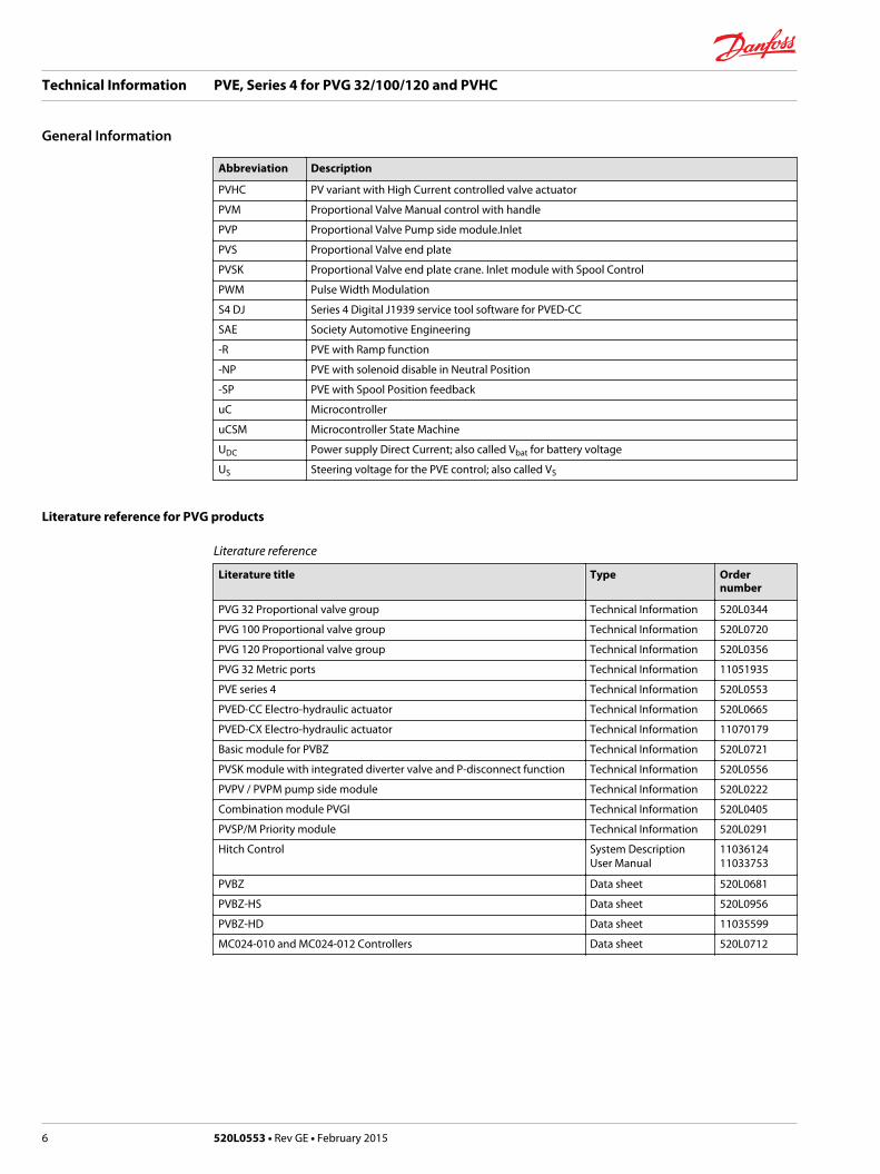
Literature reference for PVG products
Literature reference
Literature title Type Ordernumber
PVG 32 Proportional valve group Technical Information 520L0344
PVG 100 Proportional valve group Technical Information 520L0720
PVG 120 Proportional valve group Technical Information 520L0356
PVG 32 Metric ports Technical Information 11051935
PVE series 4 Technical Information 520L0553
PVED-CC Electro-hydraulic actuator Technical Information 520L0665
PVED-CX Electro-hydraulic actuator Technical Information 11070179
Basic module for PVBZ Technical Information 520L0721
PVSK module with integrated diverter valve and P-disconnect function Technical Information 520L0556
PVPV / PVPM pump side module Technical Information 520L0222
Combination module PVGI Technical Information 520L0405
PVSP/M Priority module Technical Information 520L0291
Hitch Control System DescriptionUser Manual
1103612411033753
PVBZ Data sheet 520L0681
PVBZ-HS Data sheet 520L0956
PVBZ-HD Data sheet 11035599
MC024-010 and MC024-012 Controllers Data sheet 520L0712
Technical Information PVE, Series 4 for PVG 32/100/120 and PVHC
General Information
6 520L0553 • Rev GE • February 2015

Standards for PVE
• International Organization for Standardization ISO 13766 Earth moving machinery - Electromagneticcompatibility.
• EN 50014:1997 +A1, A2: 1999
• EN 50028: 1987. For ATEX approved PVE
‒ IEC EN 61508
‒ ISO 12100-1 / 14121
‒ EN 13849 (Safety related requirements for control systems)
‒ Machinery Directive 2006/42/EC” (1st Edition December 2009)
PVE with connector variants
Hirschmann/DIN variant Deutsch® variant AMP variant
Warnings
Please work through all warnings before implementing actuators in any application. The list of warningsmust not be seen as a full list of potential dangers. Depending on application and use other potentialdangers can occur.
Warnings are listed next to the most relevant section and repeated in a special section at the end oftechnical data. See Product warnings for more information.
W Warning
All brands and all types of directional control valves – including proportional valves – can fail and causeserious damage. It is therefore important to analyze all aspects of the application. Because theproportional valves are used in many different operation conditions and applications, the machinebuilder/ system integrator alone is responsible for making the final selection of the products – andassuring that all performance, safety and warning requirements of the application are met.
PVE series 4 introduction
PVE Series 4 is the common name for the Danfoss PVG electrical actuator. This technical informationcovers our voltage controlled PVE and our current controlled PVHC actuator. For the PVHC please see inthe PVHC sectionl. The digital actuators PVED-CC and PVED-CX are covered in their special technicalinformation.
Technical Information PVE, Series 4 for PVG 32/100/120 and PVHC
General Information
520L0553 • Rev GE • February 2015 7
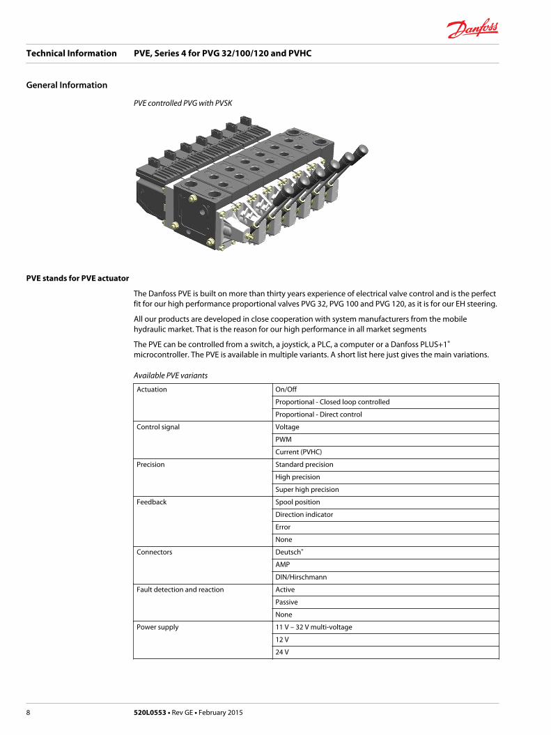
PVE controlled PVG with PVSK
PVE stands for PVE actuator
The Danfoss PVE is built on more than thirty years experience of electrical valve control and is the perfectfit for our high performance proportional valves PVG 32, PVG 100 and PVG 120, as it is for our EH steering.
All our products are developed in close cooperation with system manufacturers from the mobilehydraulic market. That is the reason for our high performance in all market segments
The PVE can be controlled from a switch, a joystick, a PLC, a computer or a Danfoss PLUS+1®
microcontroller. The PVE is available in multiple variants. A short list here just gives the main variations.
Available PVE variants
Actuation On/Off
Proportional - Closed loop controlled
Proportional - Direct control
Control signal Voltage
PWM
Current (PVHC)
Precision Standard precision
High precision
Super high precision
Feedback Spool position
Direction indicator
Error
None
Connectors Deutsch®
AMP
DIN/Hirschmann
Fault detection and reaction Active
Passive
None
Power supply 11 V – 32 V multi-voltage
12 V
24 V
Technical Information PVE, Series 4 for PVG 32/100/120 and PVHC
General Information
8 520L0553 • Rev GE • February 2015
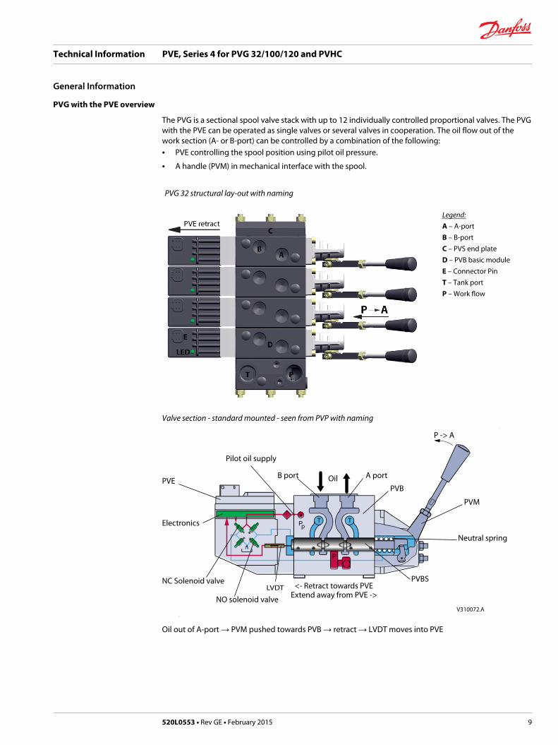
PVG with the PVE overview
The PVG is a sectional spool valve stack with up to 12 individually controlled proportional valves. The PVGwith the PVE can be operated as single valves or several valves in cooperation. The oil flow out of thework section (A- or B-port) can be controlled by a combination of the following:• PVE controlling the spool position using pilot oil pressure.
• A handle (PVM) in mechanical interface with the spool.
PVG 32 structural lay-out with naming
Legend:A – A-portB – B-portC – PVS end plateD – PVB basic moduleE – Connector PinT – Tank portP – Work flow
Valve section - standard mounted - seen from PVP with naming
V310072.A
PVE
Electronics
NC Solenoid valve
Pilot oil supply
B port Oil A port
PVB
PVM
Neutral spring
PVBS
NO solenoid valveLVDT <- Retract towards PVE
Extend away from PVE ->
P -> A
Oil out of A-port → PVM pushed towards PVB → retract → LVDT moves into PVE
Technical Information PVE, Series 4 for PVG 32/100/120 and PVHC
General Information
520L0553 • Rev GE • February 2015 9

PVG functionality
The PVG valve distributes oil from pump flow to a particular work function in the application via a specificvalve section. This is done by moving the spool (PVBS).
Depending on the choice of components the oil work flow enters the PVG through the PVP (proportionalvalve pump side module), a PVSK, a mid inlet or other system interface and enters the PVB (proportionalvalve basic module) via the P gallery and leaves through the T gallery.
The PVP/PVSK also supplies the Pilot oil pressure (Pp) for the PVE to activate the spool (PVBS). Specialdesigned float spools also allow oil flow in both directions between A- and B-port not opening to pumpnor tank.
When looking at the figure you see the valve section from PVP towards PVS with the PVM and PVEstandard mounted. When PVM and PVE are interchanged it’s called option mounted.
Valve section with naming - standard mounted - seen from PVP
V310072.A
PVE
Electronics
NC Solenoid valve
Pilot oil supply
B port Oil A port
PVB
PVM
Neutral spring
PVBS
NO solenoid valveLVDT <- Retract towards PVE
Extend away from PVE ->
P -> A
Oil out of A-port = PVM pushed towards PVB = retract = LVDT moves into PVE.
With the spool in neutral, default position when held by the neutral spring, the connection to theapplication via ports is blocked. Moving the PVBS towards the PVE, as in the figure, opens a connectionbetween P and A and also between B and T. This is done by either pushing the PVM or activating the PVE.The PVE moves the PVBS by letting Pilot Oil Pressure (Pp) push on the right end of the PVBS and releasingpressure from the left end. For details on PVG 32 please see PVG 32 Proportional Valve Groups, TechnicalInformation, 520L0334.
PVE functionality
This section has focus on how the PVE works and interacts. The description here is general and variantspecific descriptions will all refer to this.
The PVE is an electro mechanical device, meaning that functionality is depending on mechanical,hydraulic, electrical and control conditions given by PVE, PVG, application and vehicle. The result of this isthat implementing operation and safety conditions also must include vehicle specific considerations.
Hydraulic subsystems
The hydraulic subsystem is used for moving the spool and thereby open the valve for work flow.
Technical Information PVE, Series 4 for PVG 32/100/120 and PVHC
Functionality
10 520L0553 • Rev GE • February 2015

Pilot oil diagram
Pp
NC3NC1
Spool
NO4NO2
Tank
LVDT
Set point
V310073.A
1.0 [0.039]
Electronics
The hydraulic subsystem moves the spool and thereby opens the valve for work flow. The heart in thehydraulic subsystem is the solenoid valve bridge which controls the Pilot Pressure (Pp) on spool ends. Itconsist of four poppet valves, the two upper are normally closed (NC) and the two lower are normallyopen (NO).
The Pp will work against the PVBS neutral spring when the spool is moved out of blocked (neutral) andtogether with the spring when going in blocked. This combined with a larger opening in the NO than inthe NC will give a faster movement towards blocked than out of blocked.
When the PVE is powered the solenoids are all put in closed state. To move the PVBS to the right NC1 andNO4 are opened and NC3 and NO4 are kept closed.
The activation of the solenoid valves represents oil consumption and thereby also a pressure drop in thepilot oil gallery. By simultaneous use of multiple PVE the Pp can fall and result in performance problems.
The two check valves next to the NO are anti-cavitation valves. The orifice to tank reduces tank pressurespikes and can also be used for ramp function.
W Warning
Obstacles for the Pilot oil pressure (Pp) can have direct influence on spool control. Reduced Pp will limitspool control. Too high Pp can harm the PVE.
Variant of hydraulic subsystem: PVEA
Hydraulic variant: PVEA
Technical Information PVE, Series 4 for PVG 32/100/120 and PVHC
Functionality
520L0553 • Rev GE • February 2015 11
NO2 and NO4 are replaced with orifices.
W Warning
PVEA is not for use on PVG 100.
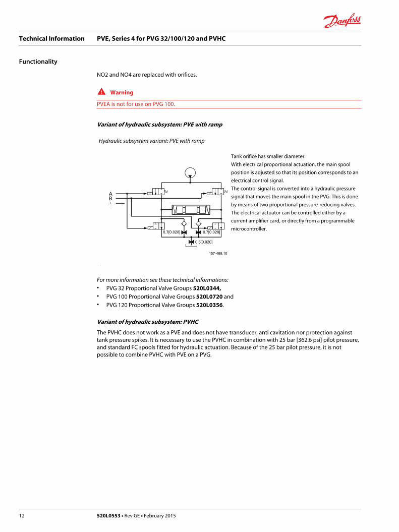
Variant of hydraulic subsystem: PVE with ramp
Hydraulic subsystem variant: PVE with ramp
Tank orifice has smaller diameter.With electrical proportional actuation, the main spoolposition is adjusted so that its position corresponds to anelectrical control signal.The control signal is converted into a hydraulic pressuresignal that moves the main spool in the PVG. This is doneby means of two proportional pressure-reducing valves.The electrical actuator can be controlled either by acurrent amplifier card, or directly from a programmablemicrocontroller.
For more information see these technical informations:• PVG 32 Proportional Valve Groups 520L0344,• PVG 100 Proportional Valve Groups 520L0720 and• PVG 120 Proportional Valve Groups 520L0356.
Variant of hydraulic subsystem: PVHC
The PVHC does not work as a PVE and does not have transducer, anti cavitation nor protection againsttank pressure spikes. It is necessary to use the PVHC in combination with 25 bar [362.6 psi] pilot pressure,and standard FC spools fitted for hydraulic actuation. Because of the 25 bar pilot pressure, it is notpossible to combine PVHC with PVE on a PVG.
Technical Information PVE, Series 4 for PVG 32/100/120 and PVHC
Functionality
12 520L0553 • Rev GE • February 2015
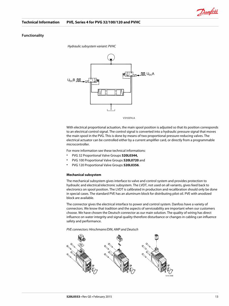
Hydraulic subsystem variant: PVHC
With electrical proportional actuation, the main spool position is adjusted so that its position correspondsto an electrical control signal. The control signal is converted into a hydraulic pressure signal that movesthe main spool in the PVG. This is done by means of two proportional pressure-reducing valves. Theelectrical actuator can be controlled either by a current amplifier card, or directly from a programmablemicrocontroller.
For more information see these technical informations:• PVG 32 Proportional Valve Groups 520L0344,• PVG 100 Proportional Valve Groups 520L0720 and• PVG 120 Proportional Valve Groups 520L0356.
Mechanical subsystem
The mechanical subsystem gives interface to valve and control system and provides protection tohydraulic and electrical/electronic subsystem. The LVDT, not used on all variants, gives feed back toelectronics on spool position. The LVDT is calibrated in production and recalibration should only be donein special cases. The standard PVE has an aluminum block for distributing pilot oil. PVE with anodizedblock are available.
The connector gives the electrical interface to power and control system. Danfoss have a variety ofconnectors. We know that tradition and the aspects of serviceability are important when our customerschoose. We have chosen the Deutsch connector as our main solution. The quality of wiring has directinfluence on water integrity and signal quality therefore disturbance or changes in cabling can influencesafety and performance.
PVE connectors: Hirschmann/DIN, AMP and Deutsch
V310 390B
Technical Information PVE, Series 4 for PVG 32/100/120 and PVHC
Functionality
520L0553 • Rev GE • February 2015 13
Electronic subsystem
The PVE (A/ H/ M/ S/ U) control signal is a low current voltage, a PWM can also be used. The PVEP hasbuild-in a PWM evaluation and cannot be controlled by proportional voltage. The control signal isreferred to as US.
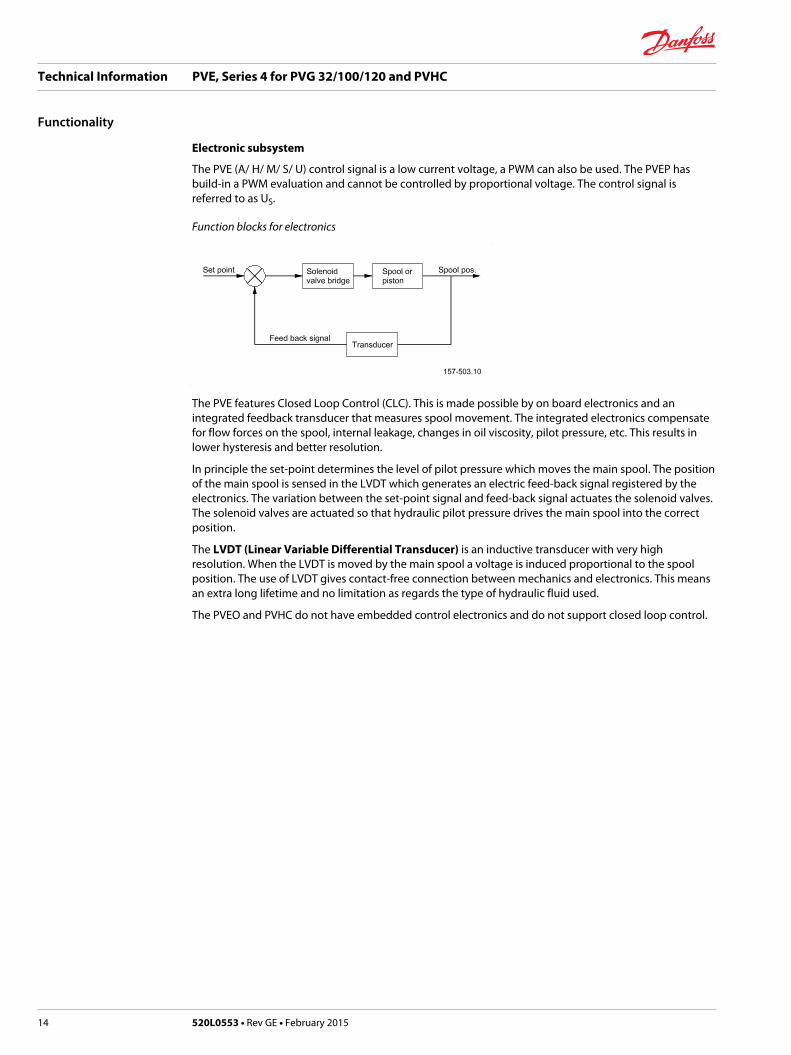
Function blocks for electronics
The PVE features Closed Loop Control (CLC). This is made possible by on board electronics and anintegrated feedback transducer that measures spool movement. The integrated electronics compensatefor flow forces on the spool, internal leakage, changes in oil viscosity, pilot pressure, etc. This results inlower hysteresis and better resolution.
In principle the set-point determines the level of pilot pressure which moves the main spool. The positionof the main spool is sensed in the LVDT which generates an electric feed-back signal registered by theelectronics. The variation between the set-point signal and feed-back signal actuates the solenoid valves.The solenoid valves are actuated so that hydraulic pilot pressure drives the main spool into the correctposition.
The LVDT (Linear Variable Differential Transducer) is an inductive transducer with very highresolution. When the LVDT is moved by the main spool a voltage is induced proportional to the spoolposition. The use of LVDT gives contact-free connection between mechanics and electronics. This meansan extra long lifetime and no limitation as regards the type of hydraulic fluid used.
The PVEO and PVHC do not have embedded control electronics and do not support closed loop control.
Technical Information PVE, Series 4 for PVG 32/100/120 and PVHC
Functionality
14 520L0553 • Rev GE • February 2015

The choice of PVE also decides the level of feedback and safety. PVE are available with fault monitoring,spool direction indication, spool position feedback and separate float control.
The fault monitoring is available in PVEA/H/S/P/U and is a utilization of the ASIC.
Direction Indication is available in PVEO/A/H and they are dual powered PVE where separate pins give anactive feedback for spool movement.
Spool position is available in PVES and is a precise feedback on a separate pin for actual spool position.
The separate float control is a protection against unintended float activation.
The PVEM, PVEO and PVHC do not have fault monitoring.
Fault monitoring and reaction
The fault monitoring system is available in two versions:• Active fault monitoring provides a warning signal and deactivates the solenoid valves. A reboot of the
PVE is required to reactivate.• Passive fault monitoring provides a warning signal only. A reboot is not required.
Both active and passive fault monitoring systems are triggered by the same four main events:1. Control signal monitoring
The Control signal voltage (US) is continuously monitored. The permissible range is between 15% and85% of the supply voltage. Outside this range the section will switch into an error state. Adisconnected US pin (floating) is recognized as neutral set point.
2. Transducer supervision
The internal LVDT wires are monitored. If the signals are interrupted or short-circuited, the PVE willswitch into an error state.
3. Supervision of spool position
The actual position must always correspond to the demanded position (US). If the actual spoolposition is further out from neutral than the demanded spool position (>12%, PVEA: >25%) or inopposite direction, the PVE will switch into an error state. With neutral/blocked setpoint the toleranceis +- 0,5 mm relative the calibrated neutral position. Spool position closer to neutral and in samedirection will not cause an error state. The situation is considered “in control”.
4. Float monitoring
Float must be entered or left within a time limit. On the six pin float PVE too high delay will cause anerror state. The float Time Outs has own thresholds. Only relevant for the six pin PVEH-F.
Active fault reaction is activated after 500 ms of error (PVEA: 750 ms).
• The solenoid valve bridge is disabled and the PVBS is released to spring control
• The error pin is powered*
• The LED change color
• The state is memorized and continues until PVE reboot
Passive fault reaction is activated after 250 ms of error (PVEA: 750 ms)
• The solenoid valve bridge is NOT disabled and the PVBS is NOT released
• The error pin is powered ( for PVE with direction indication both DI pins goes low by fault.)
• The LED change color
• The state is active for minimum 100 ms and is reset when error disappears
Technical Information PVE, Series 4 for PVG 32/100/120 and PVHC
Safety and monitoring
520L0553 • Rev GE • February 2015 15

W Warning
Error pins from more PVEs may not be interconnected. Not activated error pins are connected to groundand will disable any active signal. Error pins are signal pins and can only supply very limited powerconsumption.
To avoid the electronics in undefined state a general supervision of power supply (UDC) and internal clockfrequency is implemented. This function applies to PVEA, PVEH, PVEP, PVES and PVEU independently offault monitoring version and PVEM - and will not activate fault monitoring.
The solenoid valves are disabled when:
• the supply voltage exceeds 36 V
• the supply voltage falls below 8.5 V
• the internal clock frequency fails
PVE fault monitoring overview
PVE type Fault monitoring Delay before errorout
Error mode Error outputstatus
Fault outputon PVE 1)
LED light Memory(resetneeded)
PVEOPVEMPVHC
No faultmonitoring
- - - - - -
PVEAPVEHPVEPPVESPVEU
Active 500 ms(PVEA: 750 ms)
No fault Low < 2 V Green -
Input signal faults High ∼UDC Flashing red Yes
Transducer (LVDT) Constant red
Close loop fault
Passive 250 ms(PVEA: 750 ms)
No fault Low < 2 V Green -
Input signal faults High ~UDC Flashing red No
Transducer (LVDT) Constant red
Close loop fault
PVEFloatsix pin
Active 500 ms Float not active High ~UDC Constant red Yes
750 ms Float still active
1) Measured between fault output pin and ground.
W Warning
It’s up to the customer to decide on the required degree of safety for the system.
For PVE with direction indication:• both DI pins go low when error is active.
• when UDC1 is disabled, US is not monitored and defined as 50%.
Spool position feedback (-SP)
The –SP functionality is a 0.5 V to 4.5 V feedback, inverted in direction relative to US with 2.5 V as neutralvalue.
Technical Information PVE, Series 4 for PVG 32/100/120 and PVHC
Safety and monitoring
16 520L0553 • Rev GE • February 2015
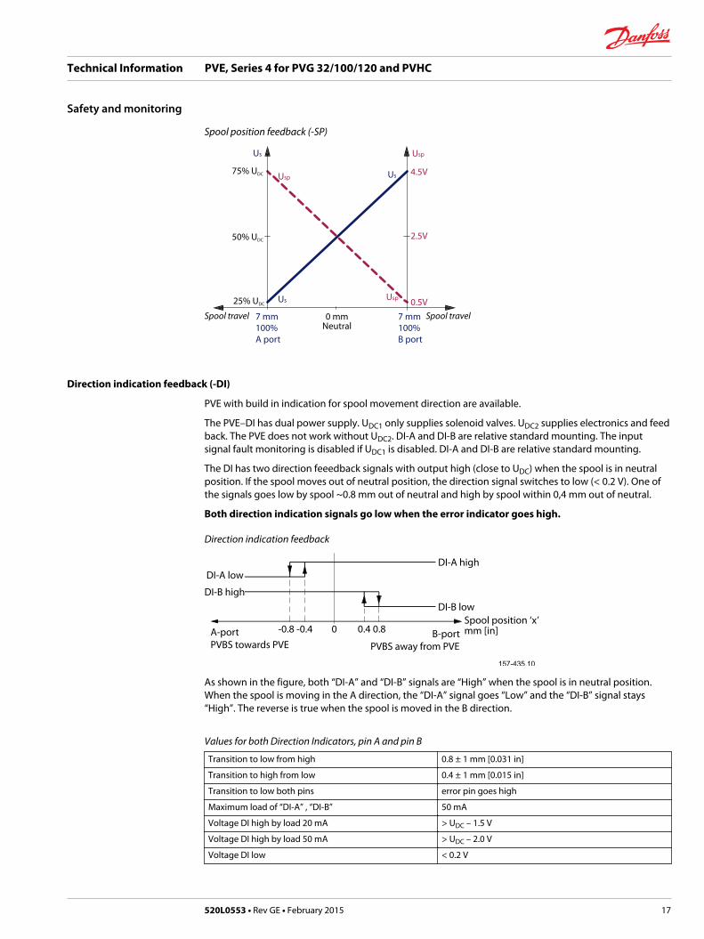
Spool position feedback (-SP)
Spool travelSpool travel0.5V
7 mm100%B port
7 mm100%A port
0 mmNeutral
2.5V
4.5V
UspUs
Us
Us
Usp
Usp25% UDC
50% UDC
75% UDC
Direction indication feedback (-DI)
PVE with build in indication for spool movement direction are available.
The PVE–DI has dual power supply. UDC1 only supplies solenoid valves. UDC2 supplies electronics and feedback. The PVE does not work without UDC2. DI-A and DI-B are relative standard mounting. The inputsignal fault monitoring is disabled if UDC1 is disabled. DI-A and DI-B are relative standard mounting.
The DI has two direction feeedback signals with output high (close to UDC) when the spool is in neutralposition. If the spool moves out of neutral position, the direction signal switches to low (< 0.2 V). One ofthe signals goes low by spool ~0.8 mm out of neutral and high by spool within 0,4 mm out of neutral.
Both direction indication signals go low when the error indicator goes high.
Direction indication feedback
DI-A low
DI-B high
DI-A high
DI-B lowSpool position ‘x’ mm [in]B-port
PVBS away from PVEA-portPVBS towards PVE
0.4 0.8-0.8 -0.4 0
As shown in the figure, both “DI-A” and “DI-B” signals are “High” when the spool is in neutral position.When the spool is moving in the A direction, the “DI-A” signal goes “Low” and the “DI-B” signal stays“High”. The reverse is true when the spool is moved in the B direction.
Values for both Direction Indicators, pin A and pin B
Transition to low from high 0.8 ± 1 mm [0.031 in]
Transition to high from low 0.4 ± 1 mm [0.015 in]
Transition to low both pins error pin goes high
Maximum load of “DI-A” , “DI-B” 50 mA
Voltage DI high by load 20 mA > UDC – 1.5 V
Voltage DI high by load 50 mA > UDC – 2.0 V
Voltage DI low < 0.2 V
Technical Information PVE, Series 4 for PVG 32/100/120 and PVHC
Safety and monitoring
520L0553 • Rev GE • February 2015 17

Solenoid disabling function (-NP)
PVEH-NP and PVEA-NP have a build in feature that disables the solenoids by US at 50% and gives afeedback on the solenoid status. This is done to facilitate application monitoring. The fault monitoring isstill activated but the closed loop will remain passive until the control signal shifts.
US disable range 48 % UDC to 52 % UDC
Solenoid disable reaction time From active to passive 750 ms <-> 1000 ms
From passive to active 0 ms <-> 50 ms
Solenoid feedback signal Maximum load 50 mA
Voltage if solenoid active by load 20mA
> UDC – 1.5 V
Voltage if solenoid active by load 50mA
> UDC – 2.0 V
Voltage if solenoid passive < 1 V
PVEH-F (six pin) has also the disable function but not the feedback. Our general recommendation isdisabling of PVE that are not in active use.
Solenoid disabling function (-NP) curves
UDC
US
Ground
Sfb
Technical Information PVE, Series 4 for PVG 32/100/120 and PVHC
Safety and monitoring
18 520L0553 • Rev GE • February 2015

All makes and all types of control valves (incl. proportional valves) can fail, thus the necessary protectionagainst the serious consequences of function failure should always be built into the system. For eachapplication an assessment should be made for the consequences of pressure failure and uncontrolled orblocked movements.
To determine the degree of protection that is required to be built into the application, system tools suchan FMEA (Failure Mode and Effect Analysis) and Hazard and Risk Analysis can be used.
FMEA – IEC EN 61508
FMEA (Failure Mode and Effect Analysis) is a tool used for analyzing potential risks. This analyticaltechnique is utilized to define, identify, and prioritize the elimination or reduction of known and/orpotential failures from a given system before it is released for production. Please refer to IEC FMEAStandard 61508.
Hazard and risk analysis ISO 12100-1 / 14121
This analysis is a tool used in new applications as it will indicate whether there are special safetyconsiderations to be met according to the machine directives EN 13849. Dependent on the determinedlevels conformity this analysis will detirmine if any extra requirements for the product design,development process, production process or maintenance, i.e. the complete product life cycle.
W Warning
All makes/brands and types of directional control valves – inclusive proportional valves – can fail andcause serious damage. It is therefore important to analyze all aspects of the application.
Because the proportional valves are used in many different operation conditions and applications,the manufacturer of the application is alone responsible for making the final selection of the products – and assuring that all performance, safety and warning requirements of the application are met.
The process of choosing the control system – and safety levels – is governed by the machine directivesEN 13849 (Safety related requirements for control systems).
Technical Information PVE, Series 4 for PVG 32/100/120 and PVHC
Safety in application
520L0553 • Rev GE • February 2015 19
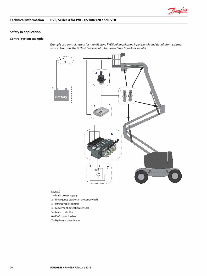
Control system example
Example of a control system for manlift using PVE Fault monitoring input signals and signals from externalsensors to ensure the PLUS+1® main controllers correct function of the manlift.
Legend:1 – Main power supply2 – Emergency stop/man present switch3 – HMI/Joystick control4 – Movement detection sensors5 – Main controller6 – PVG control valve7 – Hydraulic deactivation
Technical Information PVE, Series 4 for PVG 32/100/120 and PVHC
Safety in application
20 520L0553 • Rev GE • February 2015

Electrical block diagram for the above illustration
W Warning
It is the responsibility of the equipment manufacturer that the control system incorporated in themachine is declared as being in conformity with the relevant machine directives.
PVG 32 – mainly used in system with fixed displacement pumps:• PVSK, commonly used in crane application - full flow dump• PVPX, LS dump to tank
PVG 100 – alternative LS dump or pilot supply disconnect:• PVPP, pilot oil supply shut off• External cartridge valve connecting LS pressure or main pressure to tank
PVG 120 – pump disconnect / block for variable pumps:• PVPE, full flow dump for the PVG 120• External cartridge valve connecting LS pressure to tank
Technical Information PVE, Series 4 for PVG 32/100/120 and PVHC
Safety in application
520L0553 • Rev GE • February 2015 21

Examples of wiring block diagram
Example of a typical wiring block diagram using PVEH with neutral power off switch and fault monitoringoutput for hydraulic deactivation.
Fault detection output
high=onlow=off
Alarmlogic
2)
Memory3)
E1 E2
Output
AN
D
OR
UDC2
Error
US
Neutral detection / Supply control
signal≠neutral
OFFDelay
1)
UDC2
Error
US
PVEHwith AMP connector
PVEHwith AMP connector
Hydraulicdeactivation
Neutral detection / Supply control
signal≠neutral
OFFDelay
1)
PVE 1
PVE 2
Emergency stop
Man present switch
C
C
D
B
B
A
P301 318
A– Emergency stop / man present switch
B– PVE Fault monitoring signals
C– Neutral signal detection.
D– Hydraulic deactivation
System Control Logic e.g. PLUS+1® for signal monitoring and triggering signal for deactivation of thehydraulic system.
W Warning
It is the responsibility of the equipment manufacturer that the control system incorporated in themachine is declared as being in conformity with the relevant machine directives.
Technical Information PVE, Series 4 for PVG 32/100/120 and PVHC
Safety in application
22 520L0553 • Rev GE • February 2015

Example of fault monitoring for deactivation of the hydraulic system with extra fault inputs using the PVE’swith DI (Direction Indication) function.
Neutral detection / Supply control
signal≠neutral
OFFDelay
1)
Fault detection output
PVEH-DIAMP supply connector
PVEH-DIAMP supply connector
PVEH-DIAMP connector
PVEH-DIAMP connector
AN
D high=onlow=off
Neutral detection / Supply control
signal≠neutral
OFFDelay
1)
PVE 1
PVE 2
Fault detection
DelayDILogic Memory
US
DI-ADI-B
2)4)3)
Output
Fault detection
DelayDILogic Memory
US
DI-ADI-B
2)4)3)
Output
OR
Emergency Stop
Man present switch
P301 319
UDC2
Error
US
DI-B
Error
DI-A
UDC2
Error
US
Error
DI-A
Hydraulicdeactivation
System Control Logic e.g. PLUS+1® for signal monitoring and triggering signal for deactivation of thehydraulic system.
W Warning
It is the responsibility of the equipment manufacturer that the control system incorporated in themachine is declared as being in conformity with the relevant machine directives.
Technical Information PVE, Series 4 for PVG 32/100/120 and PVHC
Safety in application
520L0553 • Rev GE • February 2015 23

PVE control by voltage
• The PVE is controlled with a low current voltage signal.
• The spool stroke is proportional to the control voltage (US).
• The power is supplied via the supply wire (UBAT or UDC).
• The ratio US/UDC defines the actuation. For PVEU a defined voltage.
• A not connected US pin (floating) is recognized as US = ½ UDC.
PVE characteristic – control by voltage
PVEPcontrol range
PVEUfixed7.5V5V2.5V
Values for standard mounted PVE (PVEA/M/H/S)
Function Signal voltage (US)
Neutral US = 0.5 • UDC
Q: P → A US = (0.5 → 0.25) • UDC
Q: P → B US = (0.5 → 0.75) • UDC
Technical Information PVE, Series 4 for PVG 32/100/120 and PVHC
PVE control
24 520L0553 • Rev GE • February 2015

PLUS+1® Compliant
PVEA, PVEH, PVES, PVEO, PVEP and PVED can be controlled by PLUS+1®
The UDC has a capacitance of 2.2 uF which can give problems with some micro-controller power supply.Danfoss has designed a special resistance supply and control cable to eliminate this problem.
W Warning
PVEM is not PLUS+1® Compliant.
ATEX PVE
The Danfoss PVE ATEX portfolio has the same monitoring and control characteristics as the equivalentstandard PVE.
PVEU–PVE with fixed control signal range
The PVEU (PVE 0-10V) is designed for PLC/ microcontroller(uC) control hence the U. The control signal USis fixed 0 V to 10 V independent of supply voltage UDC.
Signal voltage - PVEU
Function Signal voltage PVEU
Neutral 5 V
Q: P → A 5 V → 2,5 V
Q: P → B 5 V → 7,5 V
PVE controlled with PWM signal
The standard PVE, PVEA/M/H/S, can also be controlled by a pulse with modulated PWM signal.
The V1 and V2 for PWM must be symmetrically located around UDC2 and V1≤ UDC.
Duty cycles for PVEA/PVEM/PVEH/PVES/PVEU
Function Duty cycle (dc) for PVEA/PVEM/PVEH/PVES/PVEU
Neutral 50% dc
Q: P → A 50% dc → 25% dc
Q: P → B 50% dc → 75% dc
Recommended PWM frequency for PVE
PVE type PWM frequency
PVEM > 200 Hz
PVEA/H/S/U > 1 kHz
Technical Information PVE, Series 4 for PVG 32/100/120 and PVHC
PVE control
520L0553 • Rev GE • February 2015 25

W Warning
The PWM is not evaluated by the PVE so variance/failure in period (T) will not be detected.
PVEP
The PVEP is designed for PWM control signals only.
PVEP schematic and characteristic
11 - 32 V- +
PVE
Position to PWM
PWM ratio
Set point
UsA
UsB
- B
B
Driver
Sense
DriverA
A-7.5
[-0.3]80%10%
7.5[0.3]
-
V310137.B
Spool travel
Sense
Proportional control range
mm [in]
W Warning
It is important that the power supply (UDC) is connected before the PWM signal.
PWM signals are low power voltage signals; hence no current drivers are needed.
PWM frequency can be chosen between 100 to 1000 Hz.
Current control is not possible with PVEP. The PVEP can also be connected to a control signal like used forPVHC.
The PVEP performs a true time difference measurement on the PWM input, thus there is no filtering orconversion involved.
PVEP signals
Duty cycle A-signal(pin 1)
Duty cycle B-signal(pin 2)
Function Error Pin output(pin 3)
0% 0% Neutral Low
10% 0%
0% 10%
≥ 10% ≥ 10% Fault (Error) High
< 10% 10 → 80% B-port flow Low
Technical Information PVE, Series 4 for PVG 32/100/120 and PVHC
PVE control
26 520L0553 • Rev GE • February 2015

PVEP signals (continued)
Duty cycle A-signal(pin 1)
Duty cycle B-signal(pin 2)
Function Error Pin output(pin 3)
10 → 80% < 10% A-port flow Low
A > 86% B > 86% Fault (Error) High
PVEO
PVE ON/OFF activation
The PVEO has two independent powered sets of solenoids. By powering a set of pins the actuator isactivated. By standard mounted PVE the A set gives full flow on A port and B gives on B port. Bothdirections activated at same time will keep the spool in neutral.
PVEO schematic and characteristic
W Warning
The PVEO is designed to have UDC=12 V or UDC=24 V.The solenoids might be activated by voltage down to 6 V.
PVE for float spool
Danfoss has developed two PVE variants to support the float spool. The float spool is a 4/4 spool, whereas the standard is a 4/3 spool giving another characteristic and maximum stroke. These variations arecovered by the built-in electronics. PVE for float spools are not designed for standard 4/3 spools.
There are two variants of float spool PVBS
• Float A – 0.8 mm dead band, max flow at 5.5 mm. Float at A = 8 mm, from 6.2 mm partial float.
(PVEH-F with six pin connector gives protection against entering float by using low Us. The floatsignal has priority to the Us in the PVEH-F six pin.)
• Float B – 1.5 mm dead band, max flow at 4.8 mm. Float at B = 8 mm, from 6 mm partial float.
(PVEM-F and PVEH-F with four pin connectors give no built-in protection against entering float.)
Technical Information PVE, Series 4 for PVG 32/100/120 and PVHC
PVE control
520L0553 • Rev GE • February 2015 27

Variants of the float spool PVBS
Float PVE PVBS Progressive control Float control
A PVEH-F (6 pin) Dead band 0.8 mmMax float at 5.5 mm
US: 25% -> 75% UDC UDC to float pinHas priority
B PVEH-F (4 pin) Dead band 1.5 mmMax float at 4.8 mm
US: 35% -> 65% UDC US= 75% UDC
PVE characteristic – Float A
Float = Udc
Proportional Control port B
Proportional Control port AFloat port A
PVBS maximum float is 5.5 mm [0.22 in].
PVE has six pins.
Float when special pin powered at UDC.
Technical Information PVE, Series 4 for PVG 32/100/120 and PVHC
PVE control
28 520L0553 • Rev GE • February 2015
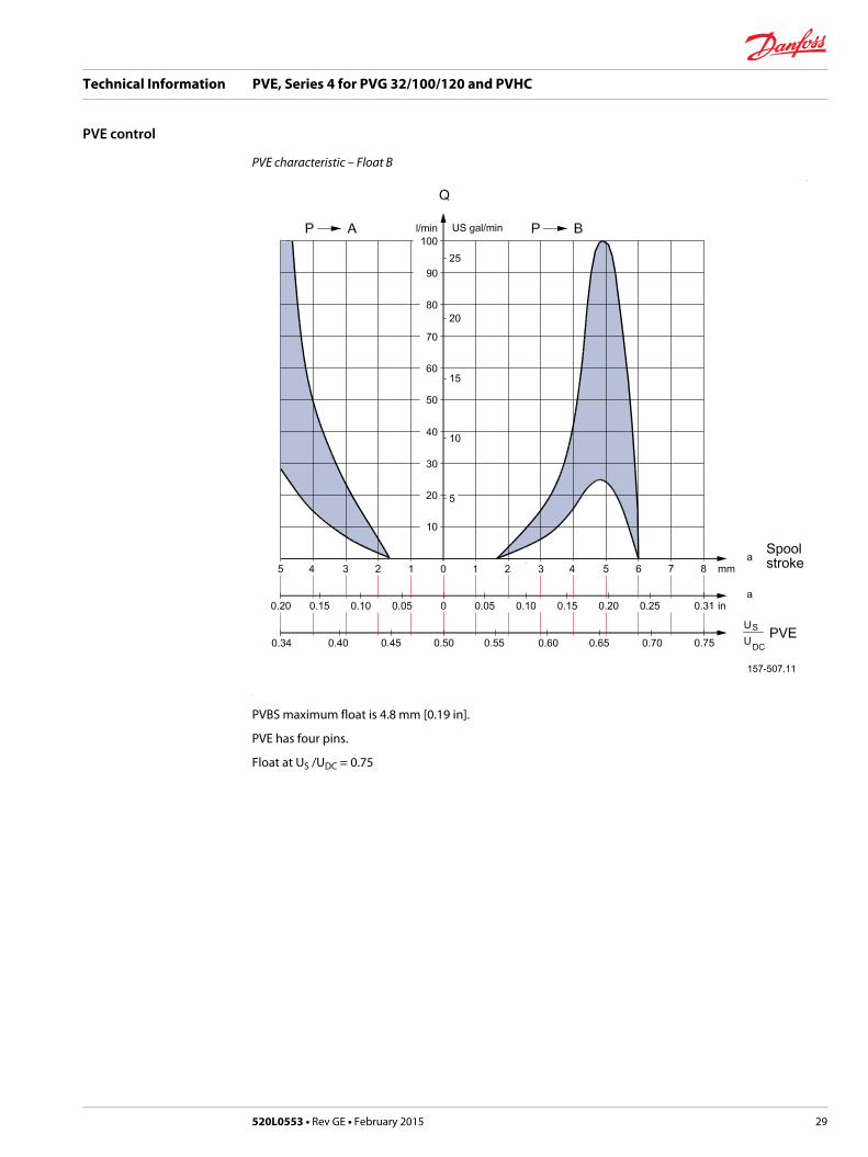
PVE characteristic – Float B
PVBS maximum float is 4.8 mm [0.19 in].
PVE has four pins.
Float at US /UDC = 0.75
Technical Information PVE, Series 4 for PVG 32/100/120 and PVHC
PVE control
520L0553 • Rev GE • February 2015 29
PVHC control
PVHC characteristic
0
400
200
600
1
2
120080
0
1000
1400
Current in mA
3
4
5
6
Spool stroke, mm
7
160040
0
200
600
1200 80
0
1000
1400
1600
200
100
300
600
400
500
700
800
200
100
300
600
400
500
700
800
@ 12V
@ 24V
V310 000.A
Ideal curve
Hysteresis
280/560 mA 500/1000 mA280/560 mA500/1000 mA
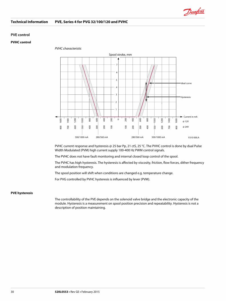
PVHC current response and hysteresis @ 25 bar Pp, 21 ctS, 25 °C. The PVHC control is done by dual PulseWidth Modulated (PVM) high current supply 100-400 Hz PWM control signals.
The PVHC does not have fault monitoring and internal closed loop control of the spool.
The PVHC has high hysteresis. The hysteresis is affected by viscosity, friction, flow forces, dither frequencyand modulation frequency.
The spool position will shift when conditions are changed e.g. temperature change.
For PVG controlled by PVHC hysteresis is influenced by lever (PVM).
PVE hysteresis
The controllability of the PVE depends on the solenoid valve bridge and the electronic capacity of themodule. Hysteresis is a measurement on spool position precision and repeatability. Hysteresis is not adescription of position maintaining.
Technical Information PVE, Series 4 for PVG 32/100/120 and PVHC
PVE control
30 520L0553 • Rev GE • February 2015
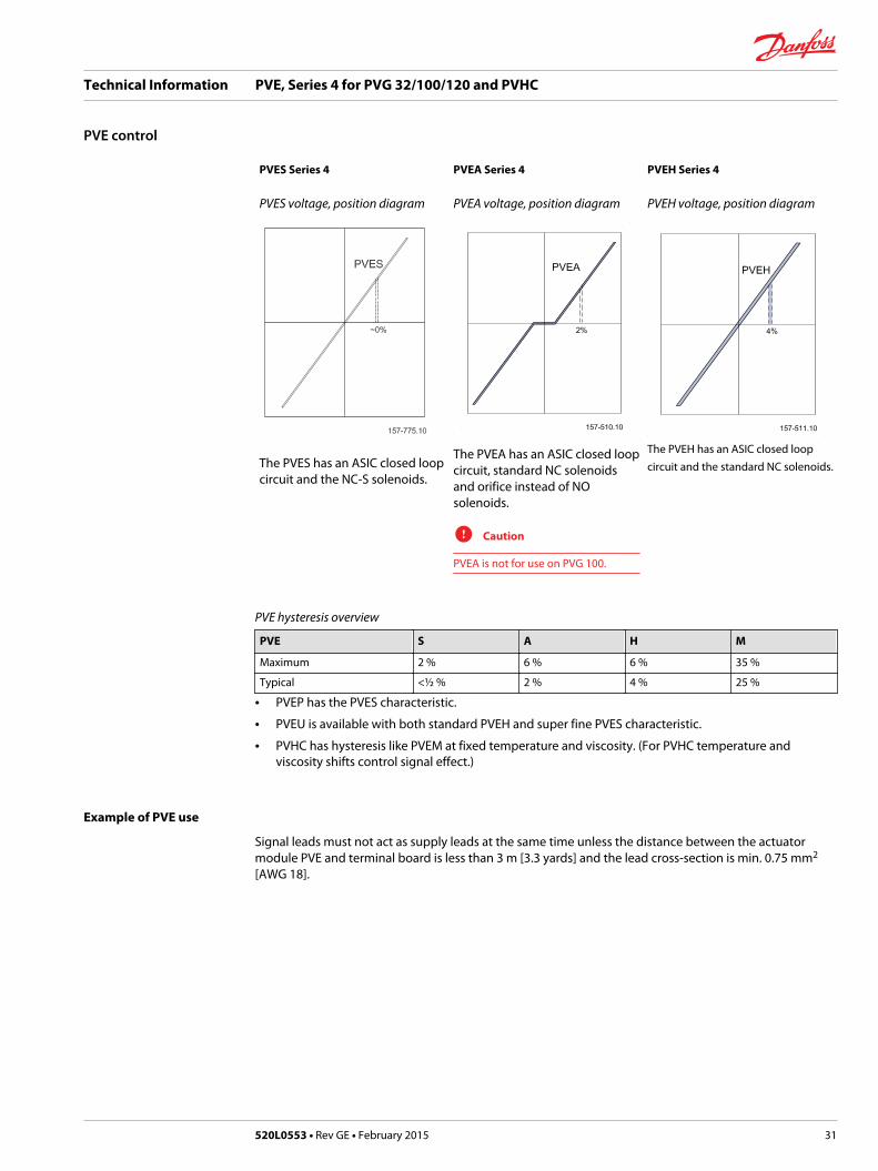
PVES Series 4 PVEA Series 4 PVEH Series 4
PVES voltage, position diagram
The PVES has an ASIC closed loopcircuit and the NC-S solenoids.
PVEA voltage, position diagram
The PVEA has an ASIC closed loopcircuit, standard NC solenoidsand orifice instead of NOsolenoids.
C Caution
PVEA is not for use on PVG 100.
PVEH voltage, position diagram
The PVEH has an ASIC closed loopcircuit and the standard NC solenoids.
PVE hysteresis overview
PVE S A H M
Maximum 2 % 6 % 6 % 35 %
Typical <½ % 2 % 4 % 25 %
• PVEP has the PVES characteristic.
• PVEU is available with both standard PVEH and super fine PVES characteristic.
• PVHC has hysteresis like PVEM at fixed temperature and viscosity. (For PVHC temperature andviscosity shifts control signal effect.)
Example of PVE use
Signal leads must not act as supply leads at the same time unless the distance between the actuatormodule PVE and terminal board is less than 3 m [3.3 yards] and the lead cross-section is min. 0.75 mm2
[AWG 18].
Technical Information PVE, Series 4 for PVG 32/100/120 and PVHC
PVE control
520L0553 • Rev GE • February 2015 31
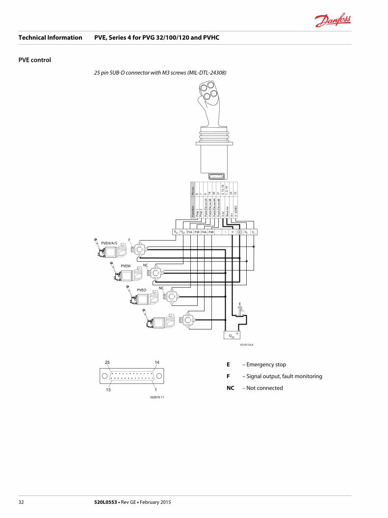
25 pin SUB-D connector with M3 screws (MIL-DTL-24308)
Push
/Dir.
sw.4
B
Push
/Dir.
sw.4
A
Push
/Dir.
sw.3
B
Push
/Dir.
sw.3
A
PVEM
PVEH/A/S
DC
V310116.A
P4B
1
PVEO
3
2
1
3
1
2
3
1
2
2
3
S2UUS1 P3BP3A P4A
Prop
2
Func
tion
Prop
1
E
U- +
U+
+-
DC
Neu
t.sw
.U
++ U -UU
- (G
ND
)
19Pin
no.
78 6 3, 1
5, 1
61,
2, 1
4102120 22
F
NC
NC
E – Emergency stop
F – Signal output, fault monitoring
NC – Not connected
Technical Information PVE, Series 4 for PVG 32/100/120 and PVHC
PVE control
32 520L0553 • Rev GE • February 2015

PVE operating parameters
Declaration of conformity
The PVEA/H/P/S/U have CE marking according to the EU directive EMC Directive 2004/108/EC. Thedeclarations are available at Danfoss.
The PVEO/M and PVHC are not subject to this directive.
W Warning
The PVE is designed for use with pilot oil supply. Use without oil supply can harm the system. The PVE isdesigned for use with pilot pressure range 10 to 15 bar [145 to 220 psi]. Intermittent pressure peaks up to50 bar [725 psi] can be accepted. Intermittent is no longer than 5 seconds and not more than once perminute.
The technical data are from typical test results. For the hydraulic system mineral based hydraulic oil witha viscosity of 21 mm2/s [102 SUS] and a temperature of 50 °C [122 °F] was used.
Oil consumption
Function Supplyvoltage
PVEA PVEH/ M/ O/ U–PVHCprop. high
PVEP /S / Uprop. super
Pilot oil flowfor PVE
neutral* OFF 0 l/min[0 US gal/min]
0 l/min[0 US gal/min]
0.3 l/min[0.106 US gal/min]
locked* ON 0.4 l/min[0.106 US gal/min]
0.1 l/min[0.026 US gal/min]
0.1 l/min[0.026 US gal/min]
continuousactuations*
1.0 l/min[0.264 US gal/min]
0.7 l/min[0.185 US gal/min]
0.8 l/min[0.211 US gal/min]
* 12 bar [174 psi] and 21 mm2/s [102 SUS]
Oil viscosity
Oil viscosity range 12 → 75 mm2/s [65 ÷ 347 SUS]
min. 4 mm2/s [39 SUS]
max. 460 mm2/s [2128 SUS]
Oil temperature
Oil temperature range 30 → 60˚C [86 ÷ 140˚F]
min. -30˚C [-22˚F]
max. 90˚C [194 ˚F]
Pilot pressure
Pilot pressure PVE(relative to T pressure)
PVHC(over tank)**
nom. 13.5 bar [196 psi] 25 bar [363 psi]
min. 10.0 bar [145 psi] 21 bar [305 psi]
max. 15.0 bar [220 psi] 25 bar [363 psi]* Designed to be used with hydraulic activated spools
Operating temperature
Minimum Maximum
Ambient -30˚C [-22˚F] 60˚C [140˚F]
Technical Information PVE, Series 4 for PVG 32/100/120 and PVHC
Technical Data
520L0553 • Rev GE • February 2015 33
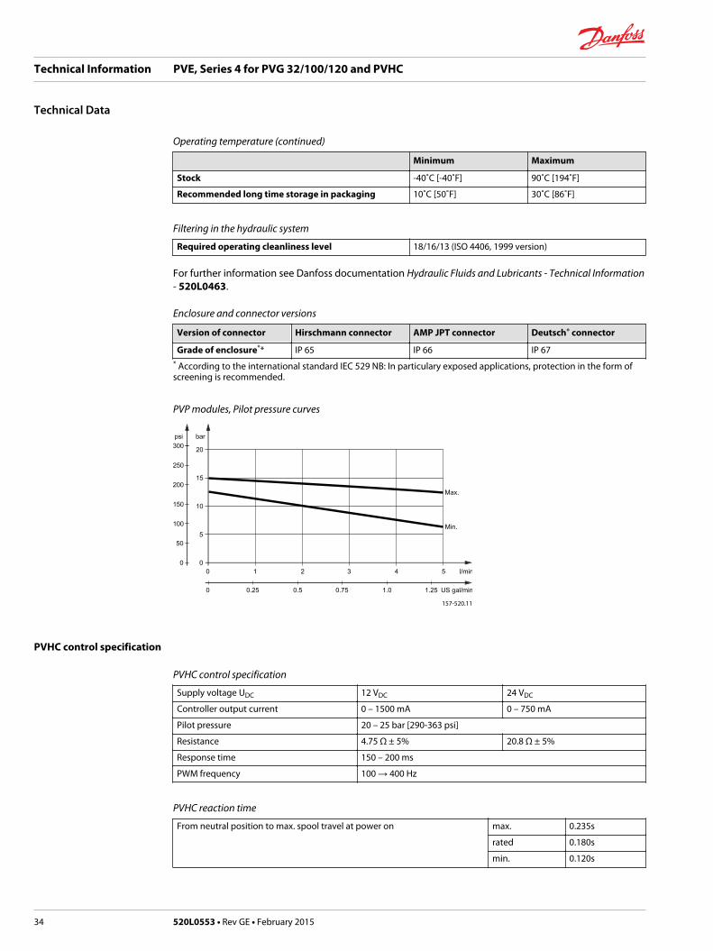
Operating temperature (continued)
Minimum Maximum
Stock -40˚C [-40˚F] 90˚C [194˚F]
Recommended long time storage in packaging 10˚C [50˚F] 30˚C [86˚F]
Filtering in the hydraulic system
Required operating cleanliness level 18/16/13 (ISO 4406, 1999 version)
For further information see Danfoss documentation Hydraulic Fluids and Lubricants - Technical Information- 520L0463.
Enclosure and connector versions
Version of connector Hirschmann connector AMP JPT connector Deutsch® connector
Grade of enclosure** IP 65 IP 66 IP 67* According to the international standard IEC 529 NB: In particulary exposed applications, protection in the form ofscreening is recommended.
PVP modules, Pilot pressure curves
157-520.11
PVHC control specification
PVHC control specification
Supply voltage UDC 12 VDC 24 VDC
Controller output current 0 – 1500 mA 0 – 750 mA
Pilot pressure 20 – 25 bar [290-363 psi]
Resistance 4.75 Ω ± 5% 20.8 Ω ± 5%
Response time 150 – 200 ms
PWM frequency 100 → 400 Hz
PVHC reaction time
From neutral position to max. spool travel at power on max. 0.235s
rated 0.180s
min. 0.120s
Technical Information PVE, Series 4 for PVG 32/100/120 and PVHC
Technical Data
34 520L0553 • Rev GE • February 2015

PVHC reaction time (continued)
From max. spool travel to neutral position at power off max. 0.175s
rated 0.090s
min. 0.065s
PVEO and PVEM control specification
PVEO and PVEM control specification
Supply voltage UDC rated 12 VDC 24 VDC
range 11 → 15 V 22 → 30 V
max. ripple 5%
Current consumption typical 740 mA 365 mA
minimum 550 mA 290 mA
maximum 820 mA 420 mA
Current via DI maximum 100 mA
PVEO and PVEM reaction time
Reaction time in seconds PVEO PVEO-R PVEM
From neutral position to max. spool travel atpower on
max. 0.235s 0.410s 0.700s
rated 0.180s 0.350s 0.450s
min. 0.120s 0.250s 0.230s
From max. spool travel to neutral position atpower off
max. 0.175s 0.330s 0.175s
rated 0.090s 0.270s 0.090s
min. 0.065s 0.250s 0.065s
From neutral position to max. spool travel byconstant power
max. – 0.550s
min. 0.210s
From max. spool travel to neutral position byconstant power
max. 0.150s
min. 0.040s
PVEA, PVEH, PVES and PVEU control specification
PVEA, PVEH, PVES and PVEU control specification
Supply voltage UDC rated 11 → 32 V
max. ripple 5 %
Current consumption at rated voltage 0.57 (33) A @ 12 V0.3 (17) A @ 24 V
Signal voltage neutral 0.5 x UDC (PVEU 5V)
A-port ↔ B-port 0.25 → 75 • UDC
Signal current at rated voltage 0.25 → 70 mA
Input impedance in relation to 0.5 • UDC 12 kΩ
Power consumption 7 (3.5) W
Error pin max current 100 mA
Technical Information PVE, Series 4 for PVG 32/100/120 and PVHC
Technical Data
520L0553 • Rev GE • February 2015 35
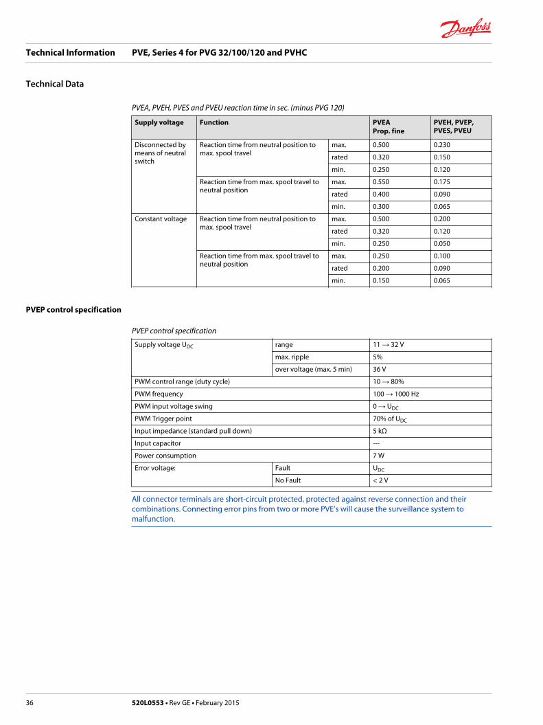
PVEA, PVEH, PVES and PVEU reaction time in sec. (minus PVG 120)
Supply voltage Function PVEAProp. fine
PVEH, PVEP,PVES, PVEU
Disconnected bymeans of neutralswitch
Reaction time from neutral position tomax. spool travel
max. 0.500 0.230
rated 0.320 0.150
min. 0.250 0.120
Reaction time from max. spool travel toneutral position
max. 0.550 0.175
rated 0.400 0.090
min. 0.300 0.065
Constant voltage Reaction time from neutral position tomax. spool travel
max. 0.500 0.200
rated 0.320 0.120
min. 0.250 0.050
Reaction time from max. spool travel toneutral position
max. 0.250 0.100
rated 0.200 0.090
min. 0.150 0.065
PVEP control specification
PVEP control specification
Supply voltage UDC range 11 → 32 V
max. ripple 5%
over voltage (max. 5 min) 36 V
PWM control range (duty cycle) 10 → 80%
PWM frequency 100 → 1000 Hz
PWM input voltage swing 0 → UDC
PWM Trigger point 70% of UDC
Input impedance (standard pull down) 5 kΩ
Input capacitor ---
Power consumption 7 W
Error voltage: Fault UDC
No Fault < 2 V
All connector terminals are short-circuit protected, protected against reverse connection and theircombinations. Connecting error pins from two or more PVE’s will cause the surveillance system tomalfunction.
Technical Information PVE, Series 4 for PVG 32/100/120 and PVHC
Technical Data
36 520L0553 • Rev GE • February 2015

PVE dimensions for PVG 32 and PVG 100
PVE with Hirschmann connector
PVE with AMP connector
Technical Information PVE, Series 4 for PVG 32/100/120 and PVHC
Technical Data
520L0553 • Rev GE • February 2015 37
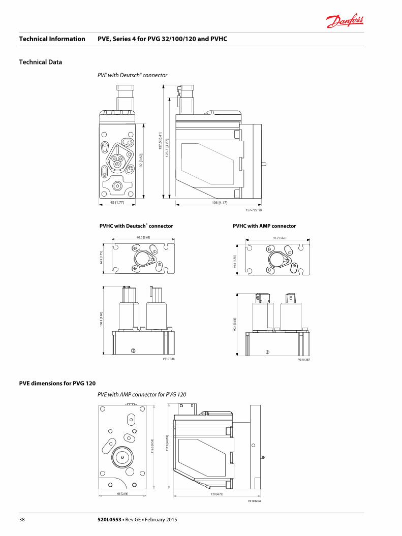
PVE with Deutsch® connector
PVHC with Deutsch® connector PVHC with AMP connector
92.2 [3.63]
100.
5 [3
.96]
44.5
[1.7
5]
V310 388
92.2 [3.63]
V310 387
90.1
[3.5
5]44
.5 [1
.75]
PVE dimensions for PVG 120
PVE with AMP connector for PVG 120
65 [2.56] 120 [4.72]
115.
5 [4
.55]
117.
8 [4
.638
]
V310320A
Technical Information PVE, Series 4 for PVG 32/100/120 and PVHC
Technical Data
38 520L0553 • Rev GE • February 2015
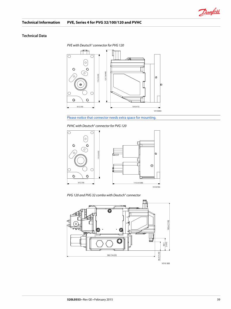
PVE with Deutsch® connector for PVG 120
65 [2.56] 120 [4.72]
V310380A
115.
5 [4
.55]
125.
7 [4
.949
]
Please notice that connector needs extra space for mounting.
PVHC with Deutsch® connector for PVG 120
65 [2.56] 114.5 [4.508]
V310378A
115.
5 [4
.55]
PVG 120 and PVG 32 combo with Deutsch® connector
362 [14.25]
36.3
[1.4
3]
50.1
[1.9
7]19
5.6
[7.7
0]
V310 383
Technical Information PVE, Series 4 for PVG 32/100/120 and PVHC
Technical Data
520L0553 • Rev GE • February 2015 39

PVEO pinout
PVEO with direction indication (DI) connection
Connector 1 A UDC B UDC Gnd Gnd
AMP (gray) p 1 p 2 p 3 p 4
Connector 2 DI-B DI-A Gnd UDC2
AMP (black) p 1 p 2 p 3 p 4
PVEO standard connection
Connector A B
AMP/Hirschmann/DIN pin 1 pin 2
Deutsch® pin 1 pin 4
Function A (pin 1) B (pin 2)
Neutral 0 0
Q: P → A UDC 0
Q: P → B 0 UDC
All PVEO Connections
Connector A B
AMP/Hirschmann/DIN pin 1 pin 2
Deutsch® pin 1 pin 4
• Ground pins are internally connected.
• Pin 3 is not connected on Hirschmann/DIN version of PVEO.
• UDC2 supplies electronics for feedback signal on PVEO-DI.
PVEO connection
AMP version of PVEO–DI AMP version of PVEO/PVEO–R
P301 104
Black connectorGrey connector
DI-B
DI-A
PVEO-DI
12
43
Pin no.
LED
U DC
U
U DC2
DC
Technical Information PVE, Series 4 for PVG 32/100/120 and PVHC
Technical Data
40 520L0553 • Rev GE • February 2015

Hirschmann/DIN version of PVEO / PVEO–R Deutsch® version of PVEO
PVEO/PVEO-R
157-502.11
DCDCU
U3
12
PVE standard connection data / pinout
PVEA /PVEH / PVEM / PVES / PVEU connection (also with float B, 4–pin)
Connector US UDC Gnd Error
AMP pin 1 pin 2 pin 3 pin 4
Hirschmann/DIN pin 2 pin 1 gnd pin 3
Deutsch® pin 1 pin 4 pin 3 pin 2
On PVEM the error pin is not used and not connected (pin 3 Hirschmann/DIN). Ground pins are internallyconnected.
Control (US) for standard mounted PVEA / PVEH / PVEM / PVES
Function Voltage relative PWM
Neutral 0.5 • UDC 50%
Q: P → A 0.5 → 0.25 • UDC 50% → 25%
Q: P → B 0.5 → 0.75 • UDC 50% → 75%
Control (US) for standard mounted PVEU
Function PVEU
Neutral 5 V
Q: P → A 5 V → 2.5 V
Q: P → B 5 V → 7.5 V
Control (US) for standard mounted PVEH /PVEM float B, 4–pin version
Function Voltage relative PWM
Neutral 0.5 • UDC 50%
Q: P → A 0.5 → 0.34 • UDC 50% → 34%
Q: P → B 0.5 → 0.65 • UDC 50% → 65%
Float 0.75 • UDC 75%
PVEM is not PLUS+1® Compliant.
Technical Information PVE, Series 4 for PVG 32/100/120 and PVHC
Technical Data
520L0553 • Rev GE • February 2015 41

PVE standard connections
AMP version Hirschmann/DIN
157-500.10
Grey connector
PVEA/PVEH/PVES
12
43
Pin no.
LED
Error
UU DC
S
Used for PVEA/PVEH/PVES/PVEU.Used for PVEH/PVEM/PVES/PVEH float B/PVEM float B.
Deutsch® version
LED
Used for PVEA/PVEH/PVES/PVEU/PVEH float B.
Standard PVE with DI
Connection PVE with direction indication (DI)
Connector 1 US UDC1 Gnd Error
AMP (gray) p 1 p 2 p 3 p 4
Deutsch® p 1 p 4 p 3 p 2
Connector 2 DI-B DI-A Gnd UDC2
AMP (black) p 1 p 2 p 3 p 4
Deutsch® p 4 p 3 p 2 p 1Ground pinsare internallyconnected.
• UDC2 only supplies electronics for feedback signal and error pin on PVEA-DI / PVEH-DI. Two separatepower sources can be used.
AMP version: PVEA–DI/PVEH–DI Deutsch® version: PVEA–DI/PVEH–DI
Black connectorGrey connector
DI-B
DI-A
PVEA-DI/PVEH-DI
12
43
Pin no.
LED
U DC1
SU
Error U DC2
P301 105
21
Error34US
UDC UDC2
DI-BDI-A2
134
PVEA-DI/PVEH-DI
LED
Technical Information PVE, Series 4 for PVG 32/100/120 and PVHC
Technical Data
42 520L0553 • Rev GE • February 2015

Standard PVE with SP
Connection PVE with Spool Position (SP)
Connector US Error SP Gnd UDC
Deutsch p 1 p 2 p 4 p 5 p 6
Deutsch version: PVES–SP
Not connected
Error
Us
321
456
Spool position
PVES-SP
UDC
LED
Standard PVE with NP
Connection PVE with Neutral Power off (NP)
Connector US Error Sfb Gnd UDC
Deutsch® p 1 p 2 p 4 p 5 p 6
Control (US) for standard mounted PVEA–DI/ PVEH–DI, PVES-SP, PVEA-NP, PVEH-NP
Function US PWM
Neutral 0.5 • UDC 50%
Q: P → A 0.5 → 0.25 • UDC 50% → 25%
Q: P → B 0.5 → 0.75 • UDC 50% → 75%
Deutsch® version: PVES–NP
Notconnected
Error
Us
321
456
Sfb
PVES-SP
UDC
LED
PVHC connection
• 100-400 Hz PWM control signals.
• Each connector controls one direction and must have UDC and ground
• No constraints on pin for UDC and ground.
Technical Information PVE, Series 4 for PVG 32/100/120 and PVHC
Technical Data
520L0553 • Rev GE • February 2015 43

Input control
Parameter Control range
12 V 24 V
Controller output current range 0 - 1500 mA 0 - 750 mA
PVHC with AMP version PVHC with Deutsch® version
74.0[2.913]
92.25[3.631]
5.75[0.226]
16.5[0.650]
33.0 [1.299]
44.4 [1.748]
5.7[0.224]
5.7[0.224]
26.75[1.053]
P301 123
74.0[2.913]
92.25[3.631]
26.75[1.053]
33.0 [1.299]
44.4 [1.748]
5.7[0.224]
5.7[0.224]
5.75[0.226]
16.5[0.650]
P301 124
PVE with separate float pin
PVEH with float A, 6–pin connection
Connector US UDC Float Ground Error
AMP pin 1 pin 2 pin 5 pin 3 pin 4
Deutsch® pin 1 pin 6 pin 3 pin 5 pin 2
AMP with separate float pin Deutsch® version with separate float pin
LED
Float
Not con-nected
Error
157-779
Float
Error
Us
321
456
No con-nection
PVEH-F
UDC
LED
PVEP with controled PWM
PVEP connection
Connector PWM A Error PWM B Gnd UDC
Deutsch® p 1 p 2 p 3 p 5 p 6
Technical Information PVE, Series 4 for PVG 32/100/120 and PVHC
Technical Data
44 520L0553 • Rev GE • February 2015

Control (US) for standard mounted PVEP
Function Voltage relative PWM
Neutral < 10% < 10%
Q: P → A 10% → 80% < 10%
Q: P → B < 10% 10% → 80%
Technical Information PVE, Series 4 for PVG 32/100/120 and PVHC
Technical Data
520L0553 • Rev GE • February 2015 45
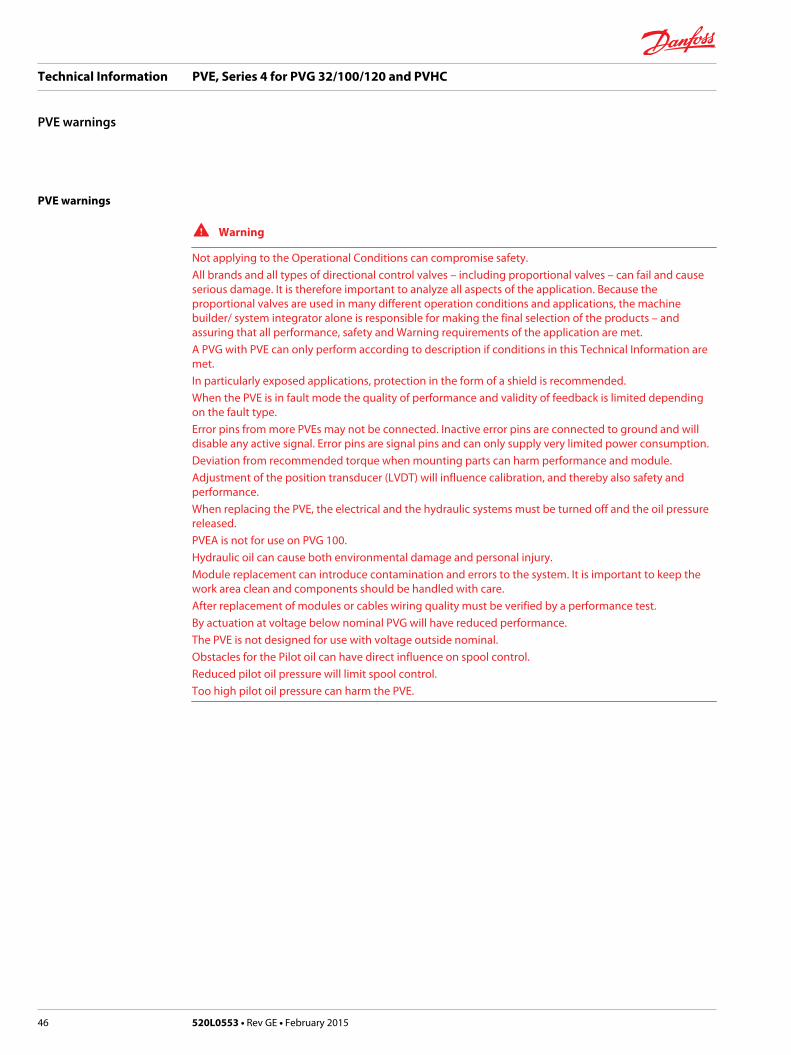
PVE warnings
W Warning
Not applying to the Operational Conditions can compromise safety.All brands and all types of directional control valves – including proportional valves – can fail and causeserious damage. It is therefore important to analyze all aspects of the application. Because theproportional valves are used in many different operation conditions and applications, the machinebuilder/ system integrator alone is responsible for making the final selection of the products – andassuring that all performance, safety and Warning requirements of the application are met.A PVG with PVE can only perform according to description if conditions in this Technical Information aremet.In particularly exposed applications, protection in the form of a shield is recommended.When the PVE is in fault mode the quality of performance and validity of feedback is limited dependingon the fault type.Error pins from more PVEs may not be connected. Inactive error pins are connected to ground and willdisable any active signal. Error pins are signal pins and can only supply very limited power consumption.Deviation from recommended torque when mounting parts can harm performance and module.Adjustment of the position transducer (LVDT) will influence calibration, and thereby also safety andperformance.When replacing the PVE, the electrical and the hydraulic systems must be turned off and the oil pressurereleased.PVEA is not for use on PVG 100.Hydraulic oil can cause both environmental damage and personal injury.Module replacement can introduce contamination and errors to the system. It is important to keep thework area clean and components should be handled with care.After replacement of modules or cables wiring quality must be verified by a performance test.By actuation at voltage below nominal PVG will have reduced performance.The PVE is not designed for use with voltage outside nominal.Obstacles for the Pilot oil can have direct influence on spool control.Reduced pilot oil pressure will limit spool control.Too high pilot oil pressure can harm the PVE.
Technical Information PVE, Series 4 for PVG 32/100/120 and PVHC
PVE warnings
46 520L0553 • Rev GE • February 2015

PVE code numbers for PVG 32 and PVG 100 use
Deutsch® connector code numbers
Feature S std. float A float B DI NP SP Fast-nomemory
ramp
Connector 1x4 1x6 1x4 2x4 1x6 1x6 1x4
PVEA* active – 157B4792 157B4796 11105542
passive 11107365
PVEH active 157B4092 157B4398 157B4096 11105543
passive 157B4093 157B4392
PVES active S 157B4892 157B4894
passive S 11089276 11108994
PVEP active S 11034832*
PVEU passive S 11089090
PVEO 12V – 157B4291 11109080
24V 157B4292 11109092* 1x6 = one plug six pins
S = super fine hysteresis, 1x4 = one plug four pins
AMP connector code numbers
Feature S std. float A DI anodized ramp-ano ramp
Connector 1x4 1x6 2x4 1x4 1x4 1x4
PVEA* active – 157B4734 157B4736
passive 157B4735 157B4737 157B4775
PVEH active 157B4034 157B4338 157B4036 157B4074
passive 157B4035 157B4037 157B4075
PVES active S 157B4834
passive S 157B4835 157B4865
PVEU active S 11089091
active – 157B4044
passive 157B4045
PVEO 12V 157B4901 11157283 157B4903
24V 157B4902 11157282 157B4272 157B4274 157B4904* 1x6 = one plug six pins
S = super fine hysteresis, 1x4 = one plug four pins
W Warning
PVEA is not for use on PVG 100.
Hirschmann/DIN connector code numbers
Feature S std. float B anodized ramp
Connector 1x4 1x4 1x4 1x4
PVEH active 157B4032 157B4332
passive 157B4033 157B4073
Technical Information PVE, Series 4 for PVG 32/100/120 and PVHC
PVE code numbers
520L0553 • Rev GE • February 2015 47
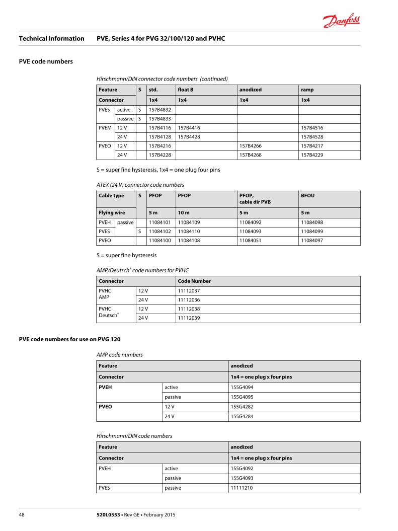
Hirschmann/DIN connector code numbers (continued)
Feature S std. float B anodized ramp
Connector 1x4 1x4 1x4 1x4
PVES active S 157B4832
passive S 157B4833
PVEM 12 V 157B4116 157B4416 157B4516
24 V 157B4128 157B4428 157B4528
PVEO 12 V 157B4216 157B4266 157B4217
24 V 157B4228 157B4268 157B4229
S = super fine hysteresis, 1x4 = one plug four pins
ATEX (24 V) connector code numbers
Cable type S PFOP PFOP PFOP,cable dir PVB
BFOU
Flying wire 5 m 10 m 5 m 5 m
PVEH passive 11084101 11084109 11084092 11084098
PVES S 11084102 11084110 11084093 11084099
PVEO 11084100 11084108 11084051 11084097
S = super fine hysteresis
AMP/Deutsch® code numbers for PVHC
Connector Code Number
PVHCAMP
12 V 11112037
24 V 11112036
PVHCDeutsch®
12 V 11112038
24 V 11112039
PVE code numbers for use on PVG 120
AMP code numbers
Feature anodized
Connector 1x4 = one plug x four pins
PVEH active 155G4094
passive 155G4095
PVEO 12 V 155G4282
24 V 155G4284
Hirschmann/DIN code numbers
Feature anodized
Connector 1x4 = one plug x four pins
PVEH active 155G4092
passive 155G4093
PVES passive 11111210
Technical Information PVE, Series 4 for PVG 32/100/120 and PVHC
PVE code numbers
48 520L0553 • Rev GE • February 2015

Hirschmann/DIN code numbers (continued)
Feature anodized
Connector 1x4 = one plug x four pins
PVEO 12 V 155G4272
24 V 155G4274
Deutsch code numbers
Feature anodized
Connector 1x4 = one plug x four pins
PVEH passive 11111206
PVES passive 11111207
PVEO 12 V 11110601
24 V 11110652
PVHC 12 V 11110597
24 V 11110598
ATEX (24 V) connector code numbers
Cable type PFOP PFOP PFOP,cable dir PVB
BFOU
Flying wire 5 m 10 m 5 m 5 m
PVEH passive 11084104 11084112 11084096 11084107
PVEO 11084103 11084111 11084095 11084106
PVE accessories
Connector code numbers
Code number Description
157B4992 AMP CONNECTING KIT(GREY)
4 pin with housing, contact and wire sealing
157B4993 AMP CONNECTING KIT(BLACK)
4 pin with housing, contact and wire sealing
984L3156 EL-PLUG, ON-OFF black Hirschmann DIN connector set*
Set of seals code numbers
Code number Description Actuator
157B4997 Set of seals PVE for PVG 32/ PVG 100
155G8519 PVE for PVG 120 (also interface plate/PVB for PVHC)
11061235 PVHC for PVG 32/ PVG 100
Technical Information PVE, Series 4 for PVG 32/100/120 and PVHC
PVE code numbers
520L0553 • Rev GE • February 2015 49

Cables code numbers
Feature Wire colors Length Code number
Connector pin 1 pin 2 pin 3 pin 4 pin 5 pin 6
Deutsch 4 pin white blue yellow red — — 4 m 11007498
4 pin white blue yellow red — — 4 m 11099720 *24V
6 pin white blue yellow red black green 4 m 11007513
AMP 4 pin white blue yellow red — — 4 m 157B4994
4 pin white blue yellow red — — 4 m 11099719 *24V
6 pin white red black yellow green blue 5 m 157B4974
AMP/black coding 4 pin white blue yellow red — — 4 m 157B4995 **-DI
Cables are with oil resistant coating.
* 24 V Special cable for use with PLUS+1® micro-controller in 24 V systems.
** -DI additional cable for PVE with direction indication.
Connector code numbers at other suppliers
Connector part numbers for purchase at other suppliers
Connector House wire sealing(blue)
JPT contact(loose piece)
sealing mat betweenmale-female part
Deutsch® female 4 pin DT06-4S — — —
6 pin DT06-6S
AMP female/gray 4 pin 2-967059-1 828904-1 929930-1 963208-1
6 pin 2-963212-1 — 963205-1
AMP female/black 4 pin 1-967059-1 —
AMP crim tool 169400-1
AMP die set for crimp tool 734253-0
These connector code numbers are not Danfoss numbers.
PVED-CC code numbers for use on PVG 32 and PVG 100
Cables code numbers for PVED-CC
Feature Wire colors Description Codenumber
Connector pin 1 pin 2 pin 3 pin 4
Deutsch® 4 pin white blue yellow red 4 m cable 11007498
AMP 4 pin white blue yellow red 4 m cable 157B4994
AMP/black 4 pin white blue yellow red 4 m cable 157B4995
Cables code numbers for PVED-CC (continued)
Feature Description Code number
Connector
Service tool interface cable/ AMP 4 m cable 157B4977
AMP 0.1m loop cable 157B4987
AMP/black Terminator 157B4988
Technical Information PVE, Series 4 for PVG 32/100/120 and PVHC
PVE code numbers
50 520L0553 • Rev GE • February 2015
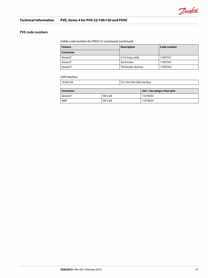
Cables code numbers for PVED-CC (continued) (continued)
Feature Description Code number
Connector
Deutsch® 0.1m loop cable 11007531
Deutsch® Terminator 11007561
Deutsch® Terminator dummy 11007563
CAN Interface
10104136 CG 150 CAN USB interface
Connector 2x4 = two plugs x four pins
Deutsch® SW 2.68 11079033
AMP SW 2.68 11079034
Technical Information PVE, Series 4 for PVG 32/100/120 and PVHC
PVE code numbers
520L0553 • Rev GE • February 2015 51


