

Racor ProductsParts, Service and Technical Information
1
2
3
4
5
6
7
8
Heavy Duty ProductsFiltration Products
Marine Fuel Filtration Products
Recycling & High Flow Filtration Systems
Interceptor Filter Products
Lubrication Filtration Systems
9 Additives
email Parker UK
www.parker.com
Alternative Fuel Filtration Systems
Crankcase Ventilation Filter Systems
Engine Air Filters
Global FiltrationTechnology
@
Help & General Information
?
w

Racor Products Section 1 Heavy Duty ProductsOn-Off Highway
Global FiltrationTechnology
Help & General Information
?
Selection
Diesel Spin On
100/200
300
300RC
400
600
Turbine
500
900
1000
73/1000
75/500
75/900
75/1000
77/1000
79/1000
Diesel Fuel Heaters
Accessories
Fittings

SELECTION -- SECTION 1
DIESEL, KEROSENE AND GASOLINE FUEL FILTERS:1. Find the application: Diesel #2, Kerosene or Gasoline.
2. Find the installation.Will the unit be installed on the suction (vacuum) or pressure side of thefuel pump? Racor units are most efficient when installed on the suction side of the fuel system.If the filter is a replaceable engine spin--on type, go directly to the 320 Engine Spin--on Series.
3. Find the fuel flow rate. You should obtain this information from your engine or equipmentmanufacturer or your Racor dealer. Use this information to select a Racor filter that has agreater flow rating than your equipment’s total fuel flow rate.
If this information is not available use the following formula for estimating.Diesel or kerosene fuel systems:
Gallons per Hour is Engine Horsepower (maximum) multiplied by 18% or GPH = HP X 0.18
Gasoline fuel systems (carbureted):Gallons per Hour is Engine Horsepower (maximum) multiplied by 10% or GPH = HP X 0.1
Gasoline fuel systems (fuel injected):Use a straight 40 GPH figure.
4. What other conditions apply?Will operations be in cold climates?An internal fuel heatermay beneeded for diesel (or kerosene)applications to reduce fuel gelling. Heaters are available with most models listed.For continuous, full--time heating see the 345RC, 360RC, & 390RC Series and the 6400 Series.
Water contamination. Awater detection package should be added to inform the operator ofwaterbuild--up and necessary servicing.Water detection packages are available for usewith allmodelsin diesel fuel applications, only.
Does the engine need to run continuously, not allowing a shut--down for needed servicing, suchas a generator? If so, see ’Turbine’ models with the ’75, or 79’ prefix in the part number.
What type of filter element best suits your vehicle? The ’Turbine’ series have element cartridgesthat are serviced from the top and all other units in this section have a removeable spin--on typecannister that is serviced from the bottom.
A convenient feature may be a priming pump. For manual hand operated pumps, see the 200and 400 Series and the model 6120N. For electric priming pumps, see the RP and Integrated Series.
5. With the above information, review the models suggested that best fit your installation.Most of the Model Groups have additional information to help in identifying the exact model foryour needs. Call your Racor distributor or Racor customer service if you need additionalassistance at: (800) 344--3286, or e--mail us from our website at www.parker.com/racor.
DIESEL AND KEROSENE FUEL SYSTEM HEATERS:1. Go directly to the Diesel Fuel Heaters Section for specific selection information.
DISCONTINUED MODELS:Occasionally, modelsmay be superceded by newproducts. The 130R, 200FGand 200 Seriesweresuperceded by the 215R, 230R and 245R Series. The 6100 was superceded by the 6400 Series.
1. Go directly to the Discontinued Models Section for available parts information.

4
Diesel Spin--On Series
Selection Information
GeneralThe Racor Diesel Spin--On Series feature a variety of compact sizes to fit in the most cramped enginecompartments.
Mounting Heads:These units all feature 1/4” NPTF ports and many have more than one inlet or outlet. All have a unitizedmounting bracket except the 140R which may be ’hard piped’ and supported by the piping.
Filters:All units feature spin--on replaceable filters and contaminant collection bowls except for the high--pressure110A. All units may be specified with an in--bowl water probe when used with diesel or kerosene applications.Danger! Do not use in--bowl water probes with gasoline applications. This may cause an explosion.
High--capacity Aquabloct filter elements, which stop water and remove solid contamination, are available in2, 10 or 30micronwithmostmodels. Equipment owners can specify their filtration needs based on application,fuel quality, operating climates and maintenance schedules.A 30 micron filter (or primary filter) is used to filter raw fuel (or poor quality fuel) before it can be further filteredby finer medias such as a 10 or 2 micron. A 10 micron filter (or secondary and even final) is used to filter fuelwhich is known to be of very good quality. A 2 micron filter (or final filter) is the finest filtration available andis the last filter used prior to engine ingestion.A simple rule to remember is the finer the filtration, the more frequent the filter change. (Carry extra filters withyour equipment).
Reusable Collection Bowls:The see--thru bowls used with these models won’t discolor from alcohol, additives or UV light and have aleak--proof, positive seal drain for easy service. Water and contaminant levels can be seen easily at a glance.Metal bowls are also available and should be specified when filtering fuels in hazardous locations whereequipment is exposed to flying gravel and debris.
Options --Available for Diesel fuel systems only.Water Probe RK21069. All units may be ordered with an in--bowl water probe to alert the operator of ahigh--water condition, even while the equipment is operating. The bowl is then drained of water at the earliestconvenience. Note: A Racor Water Detection Module is needed to work with this probe. See Accessories.Water probe RK30880 has the same features as above, except the 12 or 24 vdc electronic detection moduleis built into the probe housing and includes a detachable connector. See Accessories. Danger! Do not usein--bowl water probes with gasoline applications. This may cause an explosion.
Fuel Heater. The 215R, 230R, and 245R units may be ordered with an in--bowl 200 watt, thermostaticallycontrolled resistance heater. This design places the heat source directly below the element to maximize heattransfer. Note: An additional relay (or relay kit) may be needed to operate the fuel heater. See Accessories.
SELECTION1. Along with the information you obtained in SECTION 1, SELECTION (page 2), consider thefollowing: Are there any space limitations in the available location? The location should provideadequate space for removing the element, draining off contaminants from the bowl (and operatingthe primer pump on those applicable models).
2. What filtration rating is needed? 2, 10 or 30 micron?3. What options are needed? Priming pump, water probe and/or an in--bowl heater?
Using this information, select a unit from the next page, or check the models which follow tofind the right unit for your application.For additional information, call your Racor dealer or call Racor customer service at (209) 521--7860or (800) 344--3286, 6:00 AM to 5:00 PM, Pacific Time, or e--mail us from www.parker.com/racor.
Selection

5
Diesel Spin--On Series
Specifications
BASIC MODELS 110A 120A / 120B 140R 215R / 230R / 245R
Maximum GPH 15 15 / 20 15 15 / 30 / 45Flow Rate LPH 57 57 / 80 57 57 /114 /170
Port Size, NPTF (SAEJ476) 1/4”--18 1/4”--18 1/4”--18 1/4”--18
Service Filter Element R11 R12 / R13 Series R12 Series R15 / R20 / R25Center Threads N/A M18 X 1.5 M18 X 1.5 1”--14
Height in. 6 6.5 / 8.0 6 8.3 / 9.0 / 10.5mm 152 166 / 203 152 211 / 229 / 267
Width in. 3.2 3.2 3.2 4mm 81 81 81 102
Depth in. 3.2 3.2 3.2 4mm 81 81 81 102
Weight Lbs. 1.3 1.1 / 1.2 1.1 1.8 / 2 / 2.2(dry) kgs. .59 0.5 / 0.6 .50 .80 / .90 / 1.0
Clean Element PSI 0.15 0.15 / 0.15 0.01 0.12 / 0.31 / 0.61Pressure Drop kPa 1.03 1.03 / 1.03 0.07 0.83 / 2.14 / 4.21
Maximum AllowablePressure PSI / kPa 100/ 689 7 / 48 7 / 48 30 / 207
Bowl Water Capacityto probe tips ml 36 52 52 58(with heater) ml NA NA NA 48
Operating Temperature -- 40o / +255o F / -- 40o / +121o C
Model Illustrations
Special Notes
1. All units should be installed on the suction (vacuum) side of the fuel or transfer pump for best efficiency.2. Models 110A, 215R, 230R and 245R may be used on suction OR pressure side applications.3. Allow at least 2 inches (51 mm) clearance under the units for replacement of element and water collection.4. For additional information and availability, contact customer service at: (800) 344--3286, Pacific Time, or e--mail fromour website, www.parker.com/racor.
215R / 230R / 245R(245R shown)
120A / 120B(120A shown)
110A 140R
1Introduction

6
Diesel Spin--On Series Model 110A
110A
Performance Graphs
0
25
50
75
100
0 50 100 150
SAE J1839 Water Separation
PercentEfficient
Time (Minutes)
5/16” (8 mm) diameterclearance for fasteners.
Mounting Hole Pattern
Replacement Service ElementSERVICE ELEMENT INCLUDES LID SEAL.
R11T 10 Micron --Recommendedfor Primary or Secondary* Filtration
0.0
0.5
1.0
1.5
2.0
0 5 10 15
SAE J905 Fuel Flow Restriction*PSI X 2.036 = inHg. / PSI X 6.895 = kPa
Flow (GPH)
PSI*
0
2
4
6
8
0 5 10 15
SAE J905 Solids Capacity(using: SOFTC--2A; R11T Element)
Grams
PSI*
These results are from controlled laboratory tests. Field results may vary by application.
SPECIFICATIONS are found on Spin--On Series introduction page.
110A
1.40”(36 mm)
5.50”(140 mm)
The circled number corresponds to the item number shown in the parts list below.Parts List
1
3
4
2
Item/Part No. Description Case Qty.
1 RK21361 110A Head, 1/4”NPTF Ports 1
2 RK10110 Metal Vent Plug, 3/8”--24 1
3 RK21364 110A Housing 1
4 R11T Service Element, 10 micron 12
5 RK20022 Metal Plug, 1/2”--20 1
RK30817 Port Plug Kit, 1/4” NPT 1
RK21363 110A Gasket/O--ring Kit 1
21410 Installation Instructions, 110A
5
*Consult engine manufacturer or Racor Distributor.
Head Top View.Fuel ports are1/4”--18 NPT(SAEJ476). (Not to scale)
Basic Model 15 GPH.Two piece die--castaluminum construction
--Refer to Diesel Spin--on Series introduction pagefor filter dimensions.
7
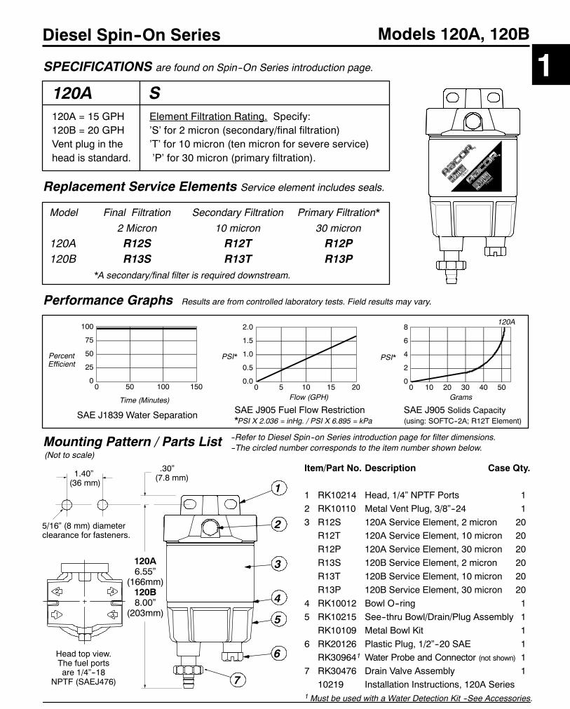
Diesel Spin--On Series Models 120A, 120B
120A
Performance Graphs
0
25
50
75
100
0 50 100 150
SAE J1839 Water Separation
PercentEfficient
Time (Minutes)
5/16” (8 mm) diameterclearance for fasteners.
Replacement Service Elements Service element includes seals.
0.0
0.5
1.0
1.5
2.0
0 5 10 15 20
SAE J905 Fuel Flow Restriction*PSI X 2.036 = inHg. / PSI X 6.895 = kPa
Flow (GPH)
PSI*
0
2
4
6
8
0 10 20 30 40 50
SAE J905 Solids Capacity(using: SOFTC--2A; R12T Element)
Grams
PSI*
SPECIFICATIONS are found on Spin--On Series introduction page.
1.40”(36 mm)
--The circled number corresponds to the item number shown below.Mounting Pattern / Parts List
1
2
3
Item/Part No. Description Case Qty.
1 RK10214 Head, 1/4” NPTF Ports 12 RK10110 Metal Vent Plug, 3/8”--24 13 R12S 120A Service Element, 2 micron 20
R12T 120A Service Element, 10 micron 20R12P 120A Service Element, 30 micron 20R13S 120B Service Element, 2 micron 20R13T 120B Service Element, 10 micron 20R13P 120B Service Element, 30 micron 20
4 RK10012 Bowl O--ring 15 RK10215 See--thru Bowl/Drain/Plug Assembly 1
RK10109 Metal Bowl Kit 16 RK20126 Plastic Plug, 1/2”--20 SAE 1
RK309641 Water Probe and Connector (not shown) 17 RK30476 Drain Valve Assembly 1
10219 Installation Instructions, 120A Series1 Must be used with a Water Detection Kit --See Accessories.
6
4
5
Head top view.The fuel portsare 1/4”--18
NPTF (SAEJ476)
120A = 15 GPH120B = 20 GPHVent plug in thehead is standard.
--Refer to Diesel Spin--on Series introduction page for filter dimensions.
Element Filtration Rating. Specify:’S’ for 2 micron (secondary/final filtration)’T’ for 10 micron (ten micron for severe service)’P’ for 30 micron (primary filtration).
Results are from controlled laboratory tests. Field results may vary.
S
(Not to scale)
1
.30”(7.8 mm)
Model Final Filtration Secondary Filtration Primary Filtration*
2 Micron 10 micron 30 micron120A R12S R12T R12P120B R13S R13T R13P
*A secondary/final filter is required downstream.
120A6.55”
(166mm)120B8.00”
(203mm)
7
120A
8
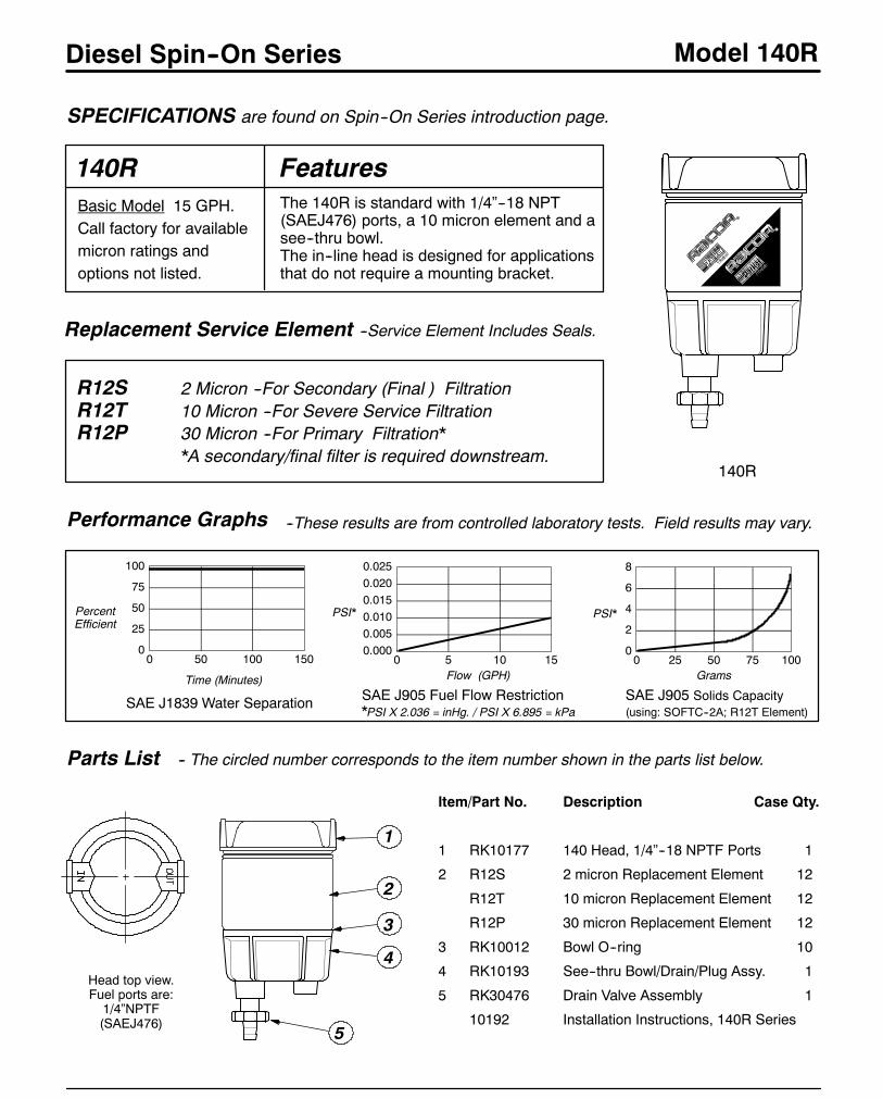
Diesel Spin--On Series Model 140R
140R
Performance Graphs
0
25
50
75
100
0 50 100 150
SAE J1839 Water Separation
PercentEfficient
Time (Minutes)
Replacement Service Element --Service Element Includes Seals.
R12S 2 Micron --For Secondary (Final ) FiltrationR12T 10 Micron --For Severe Service FiltrationR12P 30 Micron --For Primary Filtration*
*A secondary/final filter is required downstream.
0.0000.0050.0100.0150.0200.025
0 5 10 15
SAE J905 Fuel Flow Restriction*PSI X 2.036 = inHg. / PSI X 6.895 = kPa
Flow (GPH)
PSI*
0
2
4
6
8
0 25 50 75 100
SAE J905 Solids Capacity(using: SOFTC--2A; R12T Element)
Grams
PSI*
--These results are from controlled laboratory tests. Field results may vary.
SPECIFICATIONS are found on Spin--On Series introduction page.
140R
Parts List
2
1
5
3
4
Basic Model 15 GPH.Call factory for availablemicron ratings andoptions not listed.
Head top view.Fuel ports are:1/4”NPTF(SAEJ476)
-- The circled number corresponds to the item number shown in the parts list below.
The 140R is standard with 1/4”--18 NPT(SAEJ476) ports, a 10 micron element and asee--thru bowl.The in--line head is designed for applicationsthat do not require a mounting bracket.
Features
Item/Part No. Description Case Qty.
1 RK10177 140 Head, 1/4”--18 NPTF Ports 1
2 R12S 2 micron Replacement Element 12
R12T 10 micron Replacement Element 12
R12P 30 micron Replacement Element 12
3 RK10012 Bowl O--ring 10
4 RK10193 See--thru Bowl/Drain/Plug Assy. 1
5 RK30476 Drain Valve Assembly 1
10192 Installation Instructions, 140R Series
9
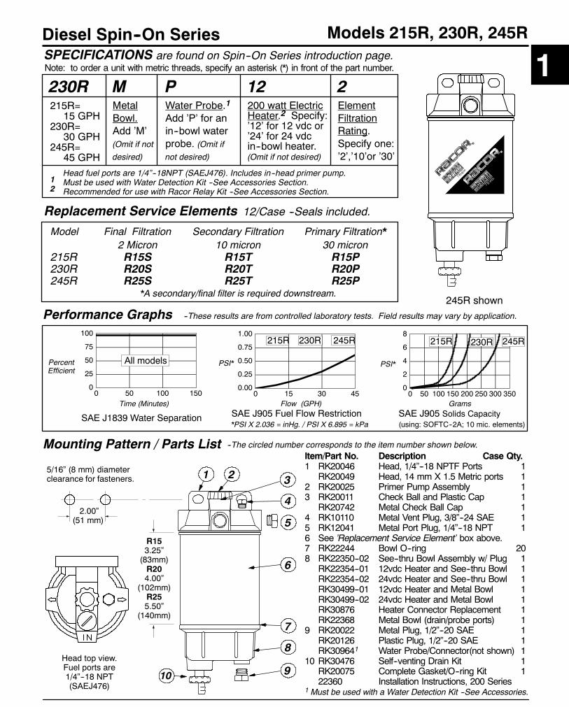
Diesel Spin--On Series Models 215R, 230R, 245R
230R
Performance Graphs
0
25
50
75
100
0 50 100 150
SAE J1839 Water Separation
PercentEfficient
Time (Minutes)
5/16” (8 mm) diameterclearance for fasteners.
Replacement Service Elements 12/Case --Seals included.
Model Final Filtration Secondary Filtration Primary Filtration*2 Micron 10 micron 30 micron
215R R15S R15T R15P230R R20S R20T R20P245R R25S R25T R25P
*A secondary/final filter is required downstream.
0.00
0.25
0.50
0.75
1.00
0 15 30 45
SAE J905 Fuel Flow Restriction*PSI X 2.036 = inHg. / PSI X 6.895 = kPa
Flow (GPH)
PSI*
0
2
4
6
8
0 50 100 150 200 250 300 350
SAE J905 Solids Capacity(using: SOFTC--2A; 10 mic. elements)
Grams
PSI*
--These results are from controlled laboratory tests. Field results may vary by application.
SPECIFICATIONS are found on Spin--On Series introduction page.Note: to order a unit with metric threads, specify an asterisk (*) in front of the part number.
245R shown
2.00”(51 mm)
--The circled number corresponds to the item number shown below.Mounting Pattern / Parts List
3
5
6
4
Item/Part No. Description Case Qty.1 RK20046 Head, 1/4”--18 NPTF Ports 1
RK20049 Head, 14 mm X 1.5 Metric ports 12 RK20025 Primer Pump Assembly 13 RK20011 Check Ball and Plastic Cap 1
RK20742 Metal Check Ball Cap 14 RK10110 Metal Vent Plug, 3/8”--24 SAE 15 RK12041 Metal Port Plug, 1/4”--18 NPT 16 See ’Replacement Service Element’ box above.7 RK22244 Bowl O--ring 208 RK22350--02 See--thru Bowl Assembly w/ Plug 1
RK22354--01 12vdc Heater and See--thru Bowl 1RK22354--02 24vdc Heater and See--thru Bowl 1RK30499--01 12vdc Heater and Metal Bowl 1RK30499--02 24vdc Heater and Metal Bowl 1RK30876 Heater Connector Replacement 1RK22368 Metal Bowl (drain/probe ports) 1
9 RK20022 Metal Plug, 1/2”--20 SAE 1RK20126 Plastic Plug, 1/2”--20 SAE 1RK309641 Water Probe/Connector(not shown) 1
10 RK30476 Self--venting Drain Kit 1RK20075 Complete Gasket/O--ring Kit 122360 Installation Instructions, 200 Series
1 Must be used with a Water Detection Kit --See Accessories.
910
7
8
215R=15 GPH
230R=30 GPH
245R=45 GPH
21
Head top view.Fuel ports are1/4”--18 NPT(SAEJ476)
P 12Water Probe.1
Add ’P’ for anin--bowl waterprobe. (Omit ifnot desired)
200 watt ElectricHeater.2 Specify:’12’ for 12 vdc or’24’ for 24 vdcin--bowl heater.(Omit if not desired)
Head fuel ports are 1/4”--18NPT (SAEJ476). Includes in--head primer pump.1 Must be used with Water Detection Kit --See Accessories Section.2 Recommended for use with Racor Relay Kit --See Accessories Section.
R153.25”(83mm)R204.00”
(102mm)R255.50”
(140mm)
All models
245R230R215R245R230R215R
12ElementFiltrationRating.Specify one:’2’,’10’or ’30’
MMetalBowl.Add ’M’(Omit if not
desired)
10
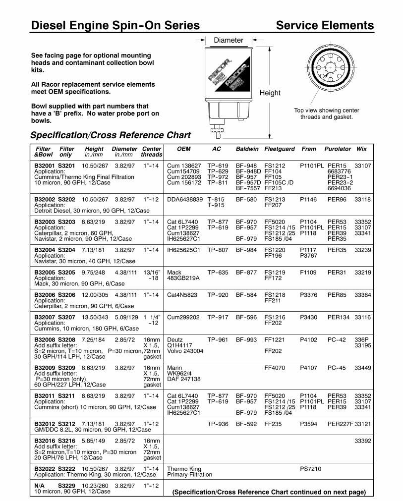
Diesel Engine Spin--On Series
Specification/Cross Reference ChartFilter Filter Height Diameter Center OEM AC Baldwin Fleetguard Fram Purolator Wix&Bowl only in./mm in./mm threads
B32001 S3201 10.50/267 3.82/97 1”--14 Cum 138627 TP--619 BF--948 FS1212 P1101PL PER15 33107Application: Cum154709 TP--629 BF--948D FF104 6683776Cummins/Thermo King Final Filtration Cum 202893 TP--972 BF--957 FF105 PER23--110 micron, 90 GPH, 12/Case Cum 156172 TP--811 BF--957D FF105C /D PER23--2
BF--7557 FF213 6694036
B32002 S3202 10.50/267 3.82/97 1”--12 DDA6438839 T--815 BF--580 FS1213 P1146 PER96 33118Application: T--915 FF207Detroit Diesel, 30 micron, 90 GPH, 12/Case
B32003 S3203 8.63/219 3.82/97 1”--14 Cat 6L7440 TP--877 BF--970 FF5020 P1104 PER53 33352Application: Cat 1P2299 TP--619 BF--957 FS1214 /15 P1101PL PER15 33107Caterpillar, 2 micron, 60 GPH, Cum138627 FS1212 /25 P1118 PER39 33341Navistar, 2 micron, 90 GPH, 12/Case IH625627C1 BF--979 FS185 /04 PER35
B32004 S3204 7.13/181 3.82/97 1”--14 IH625625C1 TP--807 BF--984 FS1220 P1117 PER35 33239Application: FF196 P3767Navistar, 30 micron, 40 GPH, 12/Case
B32005 S3205 9.75/248 4.38/111 13/16” Mack TP--635 BF--877 FS1219 F1109 PER31 33219Application: --18 483GB219A FF172Mack, 30 micron, 90 GPH, 6/Case
B32006 S3206 12.00/305 4.38/111 1”--14 Cat4N5823 TP--920 BF--584 FS1218 P3376 PER85 33384Application: FF211Caterpillar, 2 micron, 90 GPH, 6/Case
B32007 S3207 13.50/343 5.09/129 1 1/4” Cum299202 TP--917 BF--596 FS1216 P3430 PER134 33116Application: --12 FF202Cummins, 10 micron, 180 GPH, 6/Case
B32008 S3208 7.25/184 2.85/72 16mm Deutz TP--961 BF--993 FF1221 P4102 PC--42 336PAdd suffix letter: X 1.5, Q1H4117 33195S=2 micron, T=10 micron, P=30 micron,72mm Volvo 243004 FF20230 GPH/114 LPH, 12/Case gasket
B32009 S3209 8.63/219 3.82/97 16mm Mann FF4070 P4107 PC--45 33449Add suffix letter: X 1.5, WK962/4P=30 micron (only), 72mm DAF 24713860 GPH/227 LPH, 12/Case gasket
B32011 S3211 8.63/219 3.82/97 1”--14 Cat 6L7440 TP--877 BF--970 FF5020 P1104 PER53 33352Application: Cat 1P2299 TP--619 BF--957 FS1214 /15 P1101PL PER15 33107Cummins (short) 10 micron, 90 GPH, 12/Case Cum138627 FS1212 /25 P1118 PER39 33341
IH625627C1 BF--979 FS185 /04
B32012 S3212 7.13/181 3.82/97 1”--12 TP--936 BF--592 FF235 P3594 PER227F 33121GM/DDC 8.2L, 30 micron, 90 GPH, 12/Case
B32016 S3216 5.85/149 2.85/72 16mm 33392Add suffix letter: X 1.5,S=2 micron,T=10 micron, P=30 micron 72mm20 GPH/76 LPH, 12/Case gasket
B32022 S3222 10.50/267 3.82/97 1”--14 Thermo King PS7210Application: Thermo King, 30 micron, 12/Case Primary Filtration
N/A S3229 10.23/260 3.82/97 1”--1210 micron, 90 GPH, 12/Case
Top view showing centerthreads and gasket.
Height
Diameter
See facing page for optional mountingheads and contaminant collection bowlkits.
All Racor replacement service elementsmeet OEM specifications.
Bowl supplied with part numbers thathave a ’B’ prefix. No water probe port onbowls.
Service Elements
(Specification/Cross Reference Chart continued on next page)
11
Diesel Engine Spin--On SeriesSpecification/Cross Reference Chart (continued)Filter Filter Height Diameter Center OEM AC Baldwin Fleetguard Fram Purolator Wix&Bowl only in./mm in./mm threads
B32030 S3230 8.63/219 3.82/97 1”--14 4309159Application: Blue bird, 30 mic., 60 GPH, 12/Case Blue Bird School Bus
B32033 S3233 7.50/191 4.25/108 7/8--14” Cat 9Y4425 TP862 BF588 FF182 P1107 6680518 33237Application:2 micron, 60 GPH, 12/Case
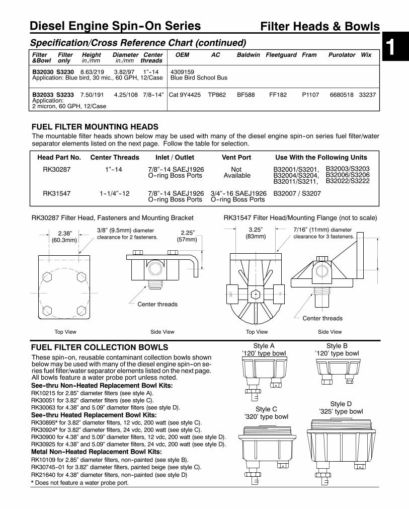
1Filter Heads & Bowls
FUEL FILTER MOUNTING HEADSThe mountable filter heads shown below may be used with many of the diesel engine spin--on series fuel filter/waterseparator elements listed on the next page. Follow the table for selection.
Head Part No. Center Threads Inlet / Outlet Vent Port Use With the Following Units
RK30287 1”--14 7/8”--14 SAEJ1926 Not B32001/S3201,O--ring Boss Ports Available B32004/S3204,
B32011/S3211,
RK31547 1--1/4”--12 7/8”--14 SAEJ1926 3/4”--16 SAEJ1926 B32007 / S3207O--ring Boss Ports O--ring Boss Ports
RK30287 Filter Head, Fasteners and Mounting Bracket
2.38”(60.3mm)
3/8” (9.5mm) diameterclearance for 2 fasteners.
2.25”(57mm)
RK31547 Filter Head/Mounting Flange (not to scale)
3.25”(83mm)
Center threads
Center threads
7/16” (11mm) diameterclearance for 3 fasteners.
Top View Side View Top View Side View
See--thru Non--Heated Replacement Bowl Kits:RK10215 for 2.85” diameter filters (see style A).RK30051 for 3.82” diameter filters (see style C).RK30063 for 4.38” and 5.09” diameter filters (see style D).See--thru Heated Replacement Bowl Kits:RK30895* for 3.82” diameter filters, 12 vdc, 200 watt (see style C).RK30924* for 3.82” diameter filters, 24 vdc, 200 watt (see style C).RK30900 for 4.38” and 5.09” diameter filters, 12 vdc, 200 watt (see style D).RK30925 for 4.38” and 5.09” diameter filters, 24 vdc, 200 watt (see style D).Metal Non--Heated Replacement Bowl Kits:RK10109 for 2.85” diameter filters, non--painted (see style B).RK30745--01 for 3.82” diameter filters, painted beige (see style C).RK21640 for 4.38” diameter filters, non--painted (see style D)* Does not feature a water probe port.
FUEL FILTER COLLECTION BOWLSThese spin--on, reusable contaminant collection bowls shownbelowmay be used with many of the diesel engine spin--on se-ries fuel filter/water separator elements listed on the next page.All bowls feature a water probe port unless noted.
Style D’325’ type bowlStyle C
’320’ type bowl
Style A’120’ type bowl
Style B’120’ type bowl
B32003/S3203B32006/S3206B32022/S3222
13
Diesel Spin--On Series
Specifications
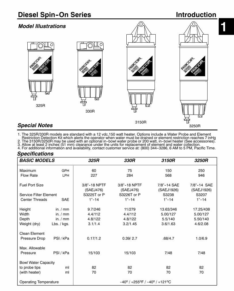
Model Illustrations
Special Notes
1. The 325R/330R models are standard with a 12 vdc,150 watt heater. Options include a Water Probe and ElementRestriction Detection Kit which alerts the operator when water must be drained or element restriction reaches 7 inHg
2. The 3150R/3250R may be used with an optional in--bowl water probe or 200 watt, in--bowl heater (See accessories).3. Allow at least 2 inches (51 mm) clearance under the units for replacement of element and water collection.4. For additional information and availability, contact customer service at: (800) 344--3286, 6 AM to 5 PM, Pacific Time.
330R
3250R
1Introduction
325R
3150R
BASIC MODELS 325R 330R 3150R 3250R
Maximum GPH 60 75 150 250Flow Rate LPH 227 284 568 946
Fuel Port Size 3/8”--18 NPTF 3/8”--18 NPTF 7/8”--14 SAE 7/8”--14 SAE(SAEJ476) (SAEJ476) (SAEJ1926) (SAEJ1926)
Service Filter Element S3225T or P S3226T or P S3238 S3207Center Threads SAE 1”--14 1”--14 1”--14 1”--14
Height in. / mm 9.7/246 11/279 13.63/346 17.25/438Width in. / mm 4.4/112 4.4/112 5.00/127 5.00/127Depth in. / mm 4.8/122 4.8/122 5.5/140 5.50/140Weight (dry) Lbs. / kgs. 3.1/1.4 3.2/1.45 3.6/1.63 4.6/2.08
Clean ElementPressure Drop PSI / kPa 0.17/1.2 0.39/ 2.7 .68/4.7 1.0/6.9
Max. AllowablePressure PSI / kPa 15/103 15/103 7/48 7/48
Bowl Water Capacityto probe tips ml 82 82 82 82(with heater) ml 70 70 70 70
Operating Temperature --40o / +255oF / --40o / +121oC

14
Diesel Spin--On Series Models 325R, 330R
325R
SPECIFICATIONS are found on Spin--On Series introduction page.
325R shown
Mounting Pattern / Parts ListItem/Part No. Description Case Qty.
1 RK22724 Mounting Filter Head 1
RK30765 Head with Vacuum Switch Port 1
2 RK22010 12 vdc, 150 watt In--Head Heater 1
3 RK20366 Heater Connector (not shown) 1
4 RK20163 Vacuum Switch (preset at 7 in.Hg.) 1
5 RK21030 Vacuum Switch Connector 1
6 See ’Replacement Service Element’ box above.
7 30965 Bowl Gasket (not shown) 1
8 RK30063 See--thru Bowl/ Wtr.Snsr.Port Plug 1
9 RK20126 Water Probe Port Plug 1
RK21069 Water Probe (not shown) 1
10 RK30476 Drain Valve and Seal 1
RK30803 Assy. Seal Service Kit (not shown) 1
30762 Installation Instructions, 325R/330R Series
325R:60 GPH/ 227 LPH330R:75 GPH/ 284 LPH
The circled number corresponds to the item number shown below.
- 10Element FiltrationRating. Specify:’10’ for 10 micron
or’30’ for 30 micron
PWater Probeand ElementRestrictionKit. Add ’P’(Omit if notdesired).
12Standard 12 vdc,150 watt ElectricIn--head Heater.’12’ must be inthe part number.
1
3.00”(76.2mm)
5/16”(8mm) diameterclearance for fasteners.
6
7
10
Model Secondary Filtration Primary Filtration*
10 micron 30 micron325R S3225T S3225P330R S3226T S3226P
*A secondary/final filter is required downstream.
Performance Graphs
0
25
50
75
100
0 50 100 150
SAE J1839 Water Separation
PercentEfficient
Time (Minutes)
0.00
0.25
0.50
0.75
0 15 30 45 60 75
SAE J905 Fuel Flow RestrictionFlow (GPH)
PSI*
SAE J905 Solids Capacity(using: SOFTC--2A; 10 mic.Elements)
Grams
PSI*
--These results are from controlled laboratory tests. Field results may vary.
0
2
4
6
8
0 100 200 300 400
325R
325R
330R 330R
How to Order --The example below illustrates how part numbers are constructed.
Replacement Service Elements --10/Case --Element seals included.
4
*PSI X 2.036 = inHg. / PSI X 6.895 = kPa
5
8
32
9
Head top view:Fuel ports are3/8”--18 NPTF(SAEJ476)
All models
15
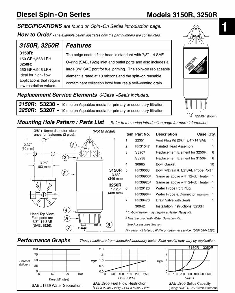
Diesel Spin--On Series Models 3150R, 3250R
Performance Graphs
0
25
50
75
100
0 50 100 150
SAE J1839 Water Separation
PercentEfficient
Time (Minutes)
3/8” (10mm) diameter clear-ance for fasteners (3 plcs).
0.0
0.5
1.0
1.5
2.0
0 50 100 150 200 250
SAE J905 Fuel Flow Restriction*PSI X 2.036 = inHg. / PSI X 6.895 = kPa
Flow (GPH)
PSI*
0
2
4
6
8
0 100 200 300 400 500 600
SAE J905 Solids Capacity(using: SOFTC--2A; 10mic.Element)
Grams
PSI*
These results are from controlled laboratory tests. Field results may vary by application.
SPECIFICATIONS are found on Spin--On Series introduction page.
3.25”(83 mm)
1
3
4
2
6
Head Top View.Fuel ports are7/8”--14 SAE(SAEJ1926).
(Not to scale)
1
Mounting Hole Pattern / Parts List --Refer to the series introduction page for more information.
3150R: S3238 -- 10 micron Aquabloc media for primary or secondary filtration.3250R: S3207 -- 10 micron Aquabloc media for primary or secondary filtration.
3150R, 3250R3150R:150 GPH/568 LPH3250R:250 GPH/946 LPHIdeal for high--flowapplications that requirelow restriction values.
How to Order --The example below illustrates how the part numbers are constructed.
Item Part No. Description Case Qty.
1 22351 Vent Plug Kit (2/kit) 3/4”--14 SAE 1
2 RK31547 Painted Head Assembly 1
3 S3207 Replacement Element for 3250R 6
S3238 Replacement Element for 3150R 6
4 30965 Bowl Gasket 10
5 RK30063 Bowl w/Drain & 1/2”SAE Probe Port 1
RK309001 Same as above with 12vdc Heater 1
RK309251 Same as above with 24vdc Heater 1
6 RK20126 Water Probe Port Plug 1
RK309642 Water Probe & Connector (not shown) 1
7 RK30476 Drain Valve with Seals 1
30942 Installation Instructions, 3250R1 In--bowl heater may require a Heater Relay Kit.
2 Must be used with Water Detection Kit.
See Accessories Section.
For parts not listed, call Racor customer service: (800) 344--3286.
FeaturesThe beige coated filter head is standard with 7/8”--14 SAE
O--ring (SAEJ1926) inlet and outlet ports and also includes a
large 3/4” SAE port for fuel priming. The spin--on replaceable
element is rated at 10 microns and the spin--on reusable
contaminant collection bowl features a self--venting drain.
2.37”(60 mm)
Replacement Service Elements 6/Case --Seals included.
5
7
3250R shown
3250R3150R
3150R13.63”(346 mm)
3250R17.25”
(438 mm)

16
Diesel Spin--On Series
Selection Information
GeneralThe Racor 300RC Diesel Spin--On Series feature a coolant heat exchanger attached to the mounting head tomaintain applied heat to keep equipment operating in very cold temperatures or climates. The compact sizeallows the units to fit in tight engine compartments.
Mounting Heads:These units all feature 3/8” NPTF fuel ports and have a unitizedmounting bracket. The coolant heat exchangeris a separate part attached with a center cap. By loosening the cap, the heat exchanger ports may be rotatedto various positions for installation convenience. All attach to 5/8” I.D. coolant hose.Note: Because of the high heat exchange efficiency of this heater, a customer supplied shut--off valve(s) willbe required for the installation.
Filters:All units feature spin--on replaceable filters and contaminant collection bowls. All units may be specified withan in--bowl water probe when used with diesel or kerosene applications.High--capacity Aquabloct filter elements, which stop water and remove solid contamination, are available in2, 10 or 30 micron. Equipment owners can specify their filtration needs based on application, fuel quality,operating climates and maintenance schedules.A 30 micron filter (or primary filter) is used to filter raw fuel (or poor quality fuel) before it can be further filteredby finer medias such as a 10 or 2 micron. A 10 micron filter (or secondary and even final) is used to filter fuelwhich is known to be of good quality. A 2 micron filter (or final filter) is the finest filtration available and is thelast filter used prior to engine ingestion.A simple rule to remember is the finer the filtration, the more frequent the filter change. (Carry extra filters withyour equipment).
Reusable Collection Bowls:The see--thru bowls used with these models won’t discolor from alcohol, additives or UV light and have aleak--proof, positive seal drain for easy service. Water and contaminant levels can be seen easily at a glance.Metal bowls are not available.
Options --Available for Diesel fuel systems only.Water Probe. All units may be ordered with an in--bowl water probe to alert the operator of a high--watercondition, evenwhile the equipment is operating. The bowl is thendrained ofwater at the earliest convenience.Note: A Racor Water Detection Module is needed to work with the probe. See Accessories.
Fuel Heater. These units may be ordered with an in--bowl 200 watt, thermostatically controlled resistanceheater. This design places the heat source directly below the element to maximize heat transfer.Note: An additional relay (or relay kit) may be needed to operate the fuel heater. See Accessories.
SELECTION1. Along with the information you obtained in SECTION 1, SELECTION (page 2), consider thefollowing: Are there any space limitations in the available location? The location should provideadequate space for removing the element and draining off contaminants from the bowl.
2. What filtration rating is needed? 2, 10 or 30 micron?3. What options are needed? Water probe and/or an in--bowl heater?
Using this information, select a unit from the next page, or check the models which follow tofind the right unit for your application.For additional information, call your Racor dealer or call Racor customer service at (209) 521--7860or (800) 344--3286, 6:00 AM to 5:00 PM, Pacific Time, or e--mail us from our website,www.parker.com/racor.
Selection

17
Diesel Spin--On Series
Specifications
BASIC MODELS 345RC 360RC 390RCMaximum GPH 45 60 90Flow Rate LPH 170 227 341
Fuel Port Size NPTF 3/8”--18 3/8”--18 3/8”--18(SAEJ476) (SAEJ476) (SAEJ476)
Coolant Barbs forHose, Inside Diameter 5/8” 5/8” 5/8”
Service Filter Element R45 Series R60 Series R90 SeriesCenter Threads SAE 1”--14 1”--14 1”--14
Height in./mm 9.3 / 236 11 / 279 11.8 / 300Width in./mm 4.4 / 112 4.4 / 112 4.4 / 112Depth in./mm 4.8 / 122 4.8 / 122 4.8 / 122Weight (dry) Lbs./kgs. 2.5 / 1.1 2.7 / 1.3 2.9 / 1.4
Clean ElementPressure Drop PSI/kPa 0.10 / 0.69 0.22 / 1.52 0.76 / 5.24
Max. AllowablePressure PSI/kPa 30 / 207 30 / 207 30 / 207
Bowl Water Capacityto probe tips ml 118 118 118(with heater) ml 104 104 104
Operating Temperature -- 40_ / +255_ F / -- 40_ / +121_ C
Model Illustrations
Special Notes
345RC
390RC
1
360RC
Introduction
1. The 345RC, 360RC, and 390RC models feature a unitized mounting head that is standard with an efficient heatexchanger which may be rotated 360_ for installation versatility. Engine coolant is used to heat the incoming fuel.
2. The heat exchanger operation is controlled manually, with customer supplied shut--off valves.3. Allow at least 2 inches (51 mm) clearance under the units for replacement of element and water collection.4. For additional information and availability, contact customer service at: (800) 344--3286, 6 AM to 5PM, Pacific Time.

18
Diesel Spin--On Series
How to Order --The example below illustrates how the part numbers are constructed.
Models 345RC, 360RC, 390RC
345RC= 45 GPH
360RC= 60 GPH
390RC= 90 GPH
Performance Graphs
0255075100
0 50 100 150
SAE J1839Water Separation
Percent Efficient
Time (Minutes)
3/8” (10 mm) diameterclearance for fasteners.
Mounting Hole Pattern --Refer to section introduction page for filter dimensions.
Replacement Service Elements --Service elements include filter seals.
Model Final Filtration Secondary Filtration Primary Filtration*2 Micron 10 Micron 30 Micron
345RC R45S R45T R45P360RC R60S R60T R60P390RC R90S R90T R90P
*A secondary/final filter is required downstream.
0.000.250.500.751.00
0.0 0.5 1.0 1.5
SAE J905 Fuel Flow Restriction*PSI X 2.036 = inHg. / PSI X 6.895 = kPa
Flow (gpm)
PSI*
SAE J905 Solids Capacity(using: SOFTC--2A and 10 micronelements)
Grams
PSI*
--These results are from controlled laboratory tests. Field results may vary.
SPECIFICATIONS are found Diesel Spin-On Series introduction page.
Head / heat exchanger top view.Fuel Ports: 3/8”--18 NPTF
Coolant Beads for 5/8” I.D. Hoses
3.00”(76.2 mm)
Water SensorProbe:1 Add ’P’for an in--bowlwater sensor.(Omit if not desired).
200 watt In--bowlElectric Heater:2
’12’ for 12 vdc’24’ for 24 vdc(Omit if not desired).
Element FiltrationRating. Specify:2 for 2 micron10 for 10 micron30 for 30 micron
360RC shown
Optional Heater Feed--thru/Connector
Optional Water SensorProbe / Connector
02468
0 100 200 300 400
345RC P 12 2
1 Must be used with Water Detection Kit. See Accessories Section.2 Recommended for use with Racor Heater Relay Kit. See Accessories Section.
Either coolantport may beused as the inletor outlet.
FuelInlet
FuelOutlet
All models360
390
345
Flow (gpm)
020406080
0.0 0.5 1.0 1.5
Heat Rise vs FlowFuel= --10_FCoolant= +190_F @4gpm.
360 390345360 390345
Temp_F
The center nutmaybe loosenedand the coolanthead rotated, ifdesired.
Not to Scale2.08”
(53 mm)
19
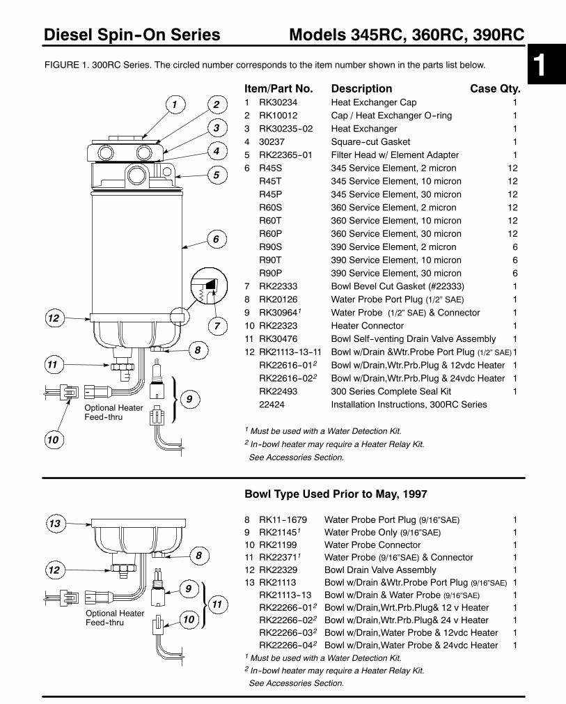
Models 345RC, 360RC, 390RCDiesel Spin--On Series
FIGURE 1. 300RC Series. The circled number corresponds to the item number shown in the parts list below.
Item/Part No. Description Case Qty.1 RK30234 Heat Exchanger Cap 12 RK10012 Cap / Heat Exchanger O--ring 13 RK30235--02 Heat Exchanger 14 30237 Square--cut Gasket 15 RK22365--01 Filter Head w/ Element Adapter 16 R45S 345 Service Element, 2 micron 12
R45T 345 Service Element, 10 micron 12R45P 345 Service Element, 30 micron 12R60S 360 Service Element, 2 micron 12R60T 360 Service Element, 10 micron 12R60P 360 Service Element, 30 micron 12R90S 390 Service Element, 2 micron 6R90T 390 Service Element, 10 micron 6R90P 390 Service Element, 30 micron 6
7 RK22333 Bowl Bevel Cut Gasket (#22333) 18 RK20126 Water Probe Port Plug (1/2” SAE) 19 RK309641 Water Probe (1/2” SAE) & Connector 110 RK22323 Heater Connector 111 RK30476 Bowl Self--venting Drain Valve Assembly 112 RK21113--13--11 Bowl w/Drain &Wtr.Probe Port Plug (1/2” SAE)1
RK22616--012 Bowl w/Drain,Wtr.Prb.Plug & 12vdc Heater 1RK22616--022 Bowl w/Drain,Wtr.Prb.Plug & 24vdc Heater 1RK22493 300 Series Complete Seal Kit 122424 Installation Instructions, 300RC Series
1 Must be used with a Water Detection Kit.2 In--bowl heater may require a Heater Relay Kit.
See Accessories Section.
6
12
Optional HeaterFeed--thru
811
1
7
1 2
3
5
4
10
13
Optional HeaterFeed--thru
8
9
10
12
11
Bowl Type Used Prior to May, 1997
8 RK11--1679 Water Probe Port Plug (9/16”SAE) 19 RK211451 Water Probe Only (9/16”SAE) 110 RK21199 Water Probe Connector 111 RK223711 Water Probe (9/16”SAE) & Connector 112 RK22329 Bowl Drain Valve Assembly 113 RK21113 Bowl w/Drain &Wtr.Probe Port Plug (9/16”SAE) 1
RK21113--13 Bowl w/Drain & Water Probe (9/16”SAE) 1RK22266--012 Bowl w/Drain,Wrt.Prb.Plug& 12 v Heater 1RK22266--022 Bowl w/Drain,Wtr.Prb.Plug& 24 v Heater 1RK22266--032 Bowl w/Drain,Water Probe & 12vdc Heater 1RK22266--042 Bowl w/Drain,Water Probe & 24vdc Heater 1
1 Must be used with a Water Detection Kit.2 In--bowl heater may require a Heater Relay Kit.See Accessories Section.
9

20
Diesel Spin--On Series
Selection Information
GeneralThe Racor 400 Diesel Spin--On Series feature a unitized priming pump and multiple fuel ports for installationconvenience. The 400 Series boasts extremely low flow resistance due to the unique pump by--pass feature.
Mounting Heads:These units all feature two inlets and outlets threaded 3/8” NPTF (except the 4120R: 3/4”--16 SAE) and havea unitized mounting bracket. All units feature a hand (palm) operated fuel priming pump to simplify serviceprocedures.
Filters:All units feature spin--on replaceable filters and contaminant collection bowls. All units may be specified withan in--bowl water probe when used with diesel or kerosene applications.
High--capacity Aquabloct filter elements, which stop water and remove solid contamination, are available in2, 10 or 30 micron. Equipment owners can specify their filtration needs based on application, fuel quality,operating climates and maintenance schedules.A 30 micron filter (or primary filter) is used to filter raw fuel (or poor quality fuel) before it can be further filteredby finer medias such as a 10 or 2 micron. A 10 micron filter (or secondary and even final) is used to filter fuelwhich is known to be of good quality. A 2 micron filter (or final filter) is the finest filtration available and is thelast filter used prior to engine ingestion.A simple rule to remember is the finer the filtration, the more frequent the filter change. (Carry extra filters withyour equipment).
Reusable Collection Bowls:The see--thru bowls used with these models won’t discolor from alcohol, additives or UV light and have aleak--proof, positive seal drain for easy service. Water and contaminant levels can be seen easily at a glance.Metal bowls are not available.
Options --Available for Diesel fuel systems only.Water Probe. All units may be ordered with an in--bowl water probe to alert the operator of a high--watercondition, evenwhile the equipment is operating. The bowl is thendrained ofwater at the earliest convenience.Note: A Racor Water Detection Module is needed to work with the probe. See Accessories. Danger! Do notuse a water probe with gasoline applications. This may cause an explosion.
Fuel Heater. These units may be ordered with an in--bowl 200 watt, thermostatically controlled resistanceheater. This design places the heat source directly below the element to maximize heat transfer.The automatic thermostat will activate the heater at 45_F and deactivate the heater at 85_F.Note: An additional relay kit may be needed to operate the fuel heater. See Accessories.
SELECTION1. Along with the information you obtained in SECTION 1, SELECTION (page 2), consider thefollowing: Are there any space limitations in the available location? The location should provideadequate space for removing the element, draining off contaminants from the bowl (and operatingthe primer pump on those applicable models).
2. What filtration rating is needed? 2, 10 or 30 micron?3. What options are needed? Water probe and/or an in--bowl heater?
Using this information, select a unit from the next page, or check the models which follow tofind the right unit for your application.For additional information, call your Racor dealer or call Racor customer service at (209) 521--7860or (800) 344--3286, 6:00 AM to 5:00 PM, Pacific Time, or e--mail us from our website,www.parker.com/racor.
Selection

21
Diesel Spin--On Series
Specifications
BASIC MODELS 445R 460R 490R 4120R
Maximum GPH 45 60 90 120Flow Rate LPH 170 227 341 454
Fuel Port Size 3/8”--18 (4) NPTF 3/8”--18 (4) NPTF 3/8”--18 (4) NPTF 3/4”--16(4) SAE
Service Filter Element R45 Series R60 Series R90 Series R120 SeriesCenter Threads SAE 1”--14 1”--14 1”--14 1”--14
Height in. / mm 9.3 / 236 11 / 279 11.8 / 300 15 / 381Width in. / mm 4.5 / 114 4.5 / 114 4.5 / 114 4.5 / 114Depth in. / mm 4.8 / 121 4.8 / 121 4.8 / 121 4.8 / 121Weight (dry) Lbs. / kgs. 2.5 / 1.1 2.7 / 1.3 2.9 / 1.4 3.9 / 1.8
Clean ElementPressure Drop PSI / kPa 0.17 / 1.2 0.39 / 2.7 0.95 / 6.5 0.85 / 5.9
Max. AllowablePressure PSI / kPa 30 / 207 30 / 207 30 / 207 15 / 103
Bowl Water Capacityto probe tips ml 118 118 118 82(with heater) ml 104 104 104 70
Operating Temperature --40o / +255o F / --40o / +121o C
Model Illustrations
Special Notes
1. All models include the hand primer pump as standard.2.Maximum power requirements for in--bowl heater options: 12vdc, 200 watt= 16.6 amps, 24vdc, 200 watt= 8.3 amps.Refer to Section 1 Accessories for available heater relay kits, if needed.
3. Allow at least 2 inches (51 mm) clearance under the units for replacement of element and water collection.4. For additional information and availability, contact customer service at: (800) 344--3286, 6 AM to 5 PM, Pacific Time.
490R460R
445R
4120R
1Introduction
22
Diesel Spin--On Series
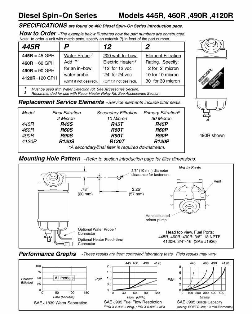
How to Order --The example below illustrates how the part numbers are constructed.Note: to order a unit with metric ports, specify an asterisk (*) in front of the part number.
Models 445R, 460R ,490R ,4120R
445R = 45 GPH
460R = 60 GPH
490R = 90 GPH
4120R=120 GPH
Performance Graphs
0
25
50
75
100
0 50 100 150
SAE J1839 Water Separation
PercentEfficient
Time (Minutes)
3/8” (10 mm) diameterclearance for fasteners.
Mounting Hole Pattern --Refer to section introduction page for filter dimensions.
Replacement Service Elements --Service elements include filter seals.
Model Final Filtration Secondary Filtration Primary Filtration*2 Micron 10 Micron 30 Micron
445R R45S R45T R45P460R R60S R60T R60P490R R90S R90T R90P4120R R120S R120T R120P
*A secondary/final filter is required downstream.
0.0
0.5
1.0
1.5
2.0
0 30 60 90 120
SAE J905 Fuel Flow Restriction*PSI X 2.036 = inHg. / PSI X 6.895 = kPa
Flow (GPH)
PSI*
SAE J905 Solids Capacity(using: SOFTC--2A; 10 mic.Elements)
Grams
PSI*
--These results are from controlled laboratory tests. Field results may vary.
SPECIFICATIONS are found on 400 Diesel Spin-On Series introduction page.
Head top view. Fuel Ports:445R, 460R, 490R: 3/8”--18 NPTF4120R: 3/4”--16 (SAE J1926)
2.25”(57 mm)
Water Probe:1
Add ’P’for an in--bowlwater probe.(Omit if not desired).
200 watt In--bowlElectric Heater:2
’12’ for 12 vdc’24’ for 24 vdc(Omit if not desired).
Element FiltrationRating. Specify:2 for 2 micron10 for 10 micron30 for 30 micron
490R shown
Optional Heater Feed--thru/Connector
Optional Water Probe /Connector
0
2
4
6
8
0 100 200 300 400 500
4120460445
Hand actuatedprimer pump
445 460 490 4120
445R P 12 2
Vent
1 Must be used with Water Detection Kit. See Accessories Section.2 Recommended for use with Racor Heater Relay Kit. See Accessories Section.
490
All models
.78”(20 mm)
Not to Scale
23
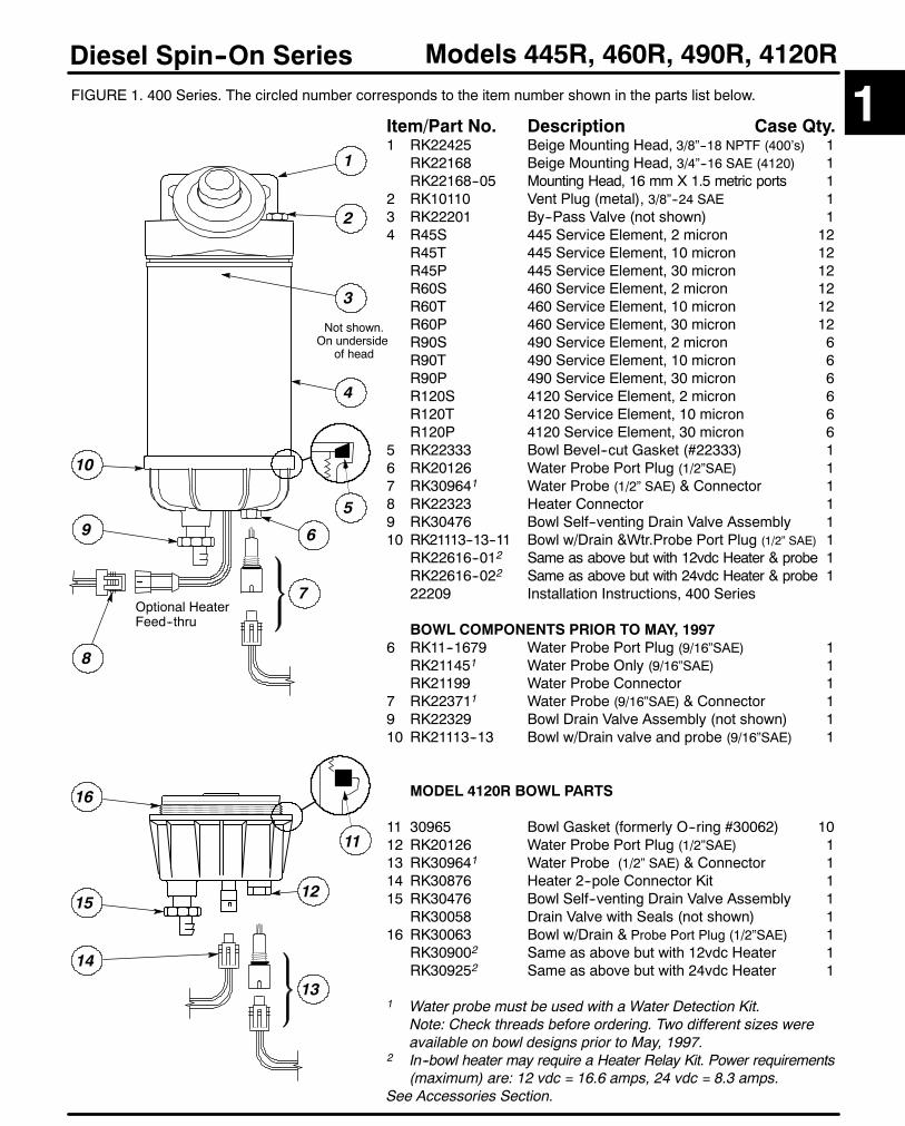
Models 445R, 460R, 490R, 4120RDiesel Spin--On SeriesFIGURE 1. 400 Series. The circled number corresponds to the item number shown in the parts list below.
Item/Part No. Description Case Qty.1 RK22425 Beige Mounting Head, 3/8”--18 NPTF (400’s) 1
RK22168 Beige Mounting Head, 3/4”--16 SAE (4120) 1RK22168--05 Mounting Head, 16 mm X 1.5 metric ports 1
2 RK10110 Vent Plug (metal), 3/8”--24 SAE 13 RK22201 By--Pass Valve (not shown) 14 R45S 445 Service Element, 2 micron 12
R45T 445 Service Element, 10 micron 12R45P 445 Service Element, 30 micron 12R60S 460 Service Element, 2 micron 12R60T 460 Service Element, 10 micron 12R60P 460 Service Element, 30 micron 12R90S 490 Service Element, 2 micron 6R90T 490 Service Element, 10 micron 6R90P 490 Service Element, 30 micron 6R120S 4120 Service Element, 2 micron 6R120T 4120 Service Element, 10 micron 6R120P 4120 Service Element, 30 micron 6
5 RK22333 Bowl Bevel--cut Gasket (#22333) 16 RK20126 Water Probe Port Plug (1/2”SAE) 17 RK309641 Water Probe (1/2” SAE) & Connector 18 RK22323 Heater Connector 19 RK30476 Bowl Self--venting Drain Valve Assembly 110 RK21113--13--11 Bowl w/Drain &Wtr.Probe Port Plug (1/2” SAE) 1
RK22616--012 Same as above but with 12vdc Heater & probe 1RK22616--022 Same as above but with 24vdc Heater & probe 122209 Installation Instructions, 400 Series
BOWL COMPONENTS PRIOR TO MAY, 19976 RK11--1679 Water Probe Port Plug (9/16”SAE) 1
RK211451 Water Probe Only (9/16”SAE) 1RK21199 Water Probe Connector 1
7 RK223711 Water Probe (9/16”SAE) & Connector 19 RK22329 Bowl Drain Valve Assembly (not shown) 110 RK21113--13 Bowl w/Drain valve and probe (9/16”SAE) 1
MODEL 4120R BOWL PARTS
11 30965 Bowl Gasket (formerly O--ring #30062) 1012 RK20126 Water Probe Port Plug (1/2”SAE) 113 RK309641 Water Probe (1/2” SAE) & Connector 114 RK30876 Heater 2--pole Connector Kit 115 RK30476 Bowl Self--venting Drain Valve Assembly 1
RK30058 Drain Valve with Seals (not shown) 116 RK30063 Bowl w/Drain & Probe Port Plug (1/2”SAE) 1
RK309002 Same as above but with 12vdc Heater 1RK309252 Same as above but with 24vdc Heater 1
1 Water probe must be used with a Water Detection Kit.Note: Check threads before ordering. Two different sizes wereavailable on bowl designs prior to May, 1997.
2 In--bowl heater may require a Heater Relay Kit. Power requirements(maximum) are: 12 vdc = 16.6 amps, 24 vdc = 8.3 amps.
See Accessories Section.
2
6
1215
14
9
16
1
11
Not shown.On underside
of head
Optional HeaterFeed--thru
7
1
3
5
4
10
8
13

24
Diesel Spin--On Series
Selection Information
GeneralThe 600 Series Diesel Fuel Filter/Water Separators feature multiple port mounting heads to fit a variety ofinstallations.
Mounting Heads:These units all feature seven tapered thread ports, four inlet and three outlet, for mounting versatility and havea unitized mounting bracket.
Filters:All units feature spin--on replaceable filters and contaminant collection bowls. All units may be specified withan in--bowl water probe when used with diesel or kerosene applications.
High--capacity Aquabloct filter elements, which stop water and remove solid contamination, are available in2, 10 or 30 micron. Equipment owners can specify their filtration needs based on application, fuel quality,operating climates and maintenance schedules.A 30 micron filter (or primary filter) is used to filter raw fuel (or poor quality fuel) before it can be further filteredby finer medias such as a 10 or 2 micron. A 10 micron filter (or secondary and even final) is used to filter fuelwhich is known to be of good quality. A 2 micron filter (or final filter) is the finest filtration available and is thelast filter used prior to engine ingestion.A simple rule to remember is the finer the filtration, the more frequent the filter change. (Carry extra filters withyour equipment).
Reusable Collection Bowls:The see--thru bowls used with these models won’t discolor from alcohol, additives or UV light and have aleak--proof, positive seal drain for easy service. Water and contaminant levels can be seen easily at a glance.Metal bowls are not available.
Options --Available for Diesel fuel systems only.Water Probe. All units may be ordered with an in--bowl water probe to alert the operator of a high--watercondition, evenwhile the equipment is operating. The bowl is thendrained ofwater at the earliest convenience.Note: A Racor Water Detection Module is needed to work with the probe. See Accessories.
Fuel Heater. These units may be ordered with an in--bowl 200 watt, thermostatically controlled resistanceheater. This design places the heat source directly below the element to maximize heat transfer.Note: An additional relay (or relay kit) may be needed to operate the fuel heater. See Accessories.
SELECTION1. Along with the information you obtained in SECTION 1, SELECTION (page 2), consider thefollowing: Are there any space limitations in the available location? The location should provideadequate space for removing the element and draining off contaminants from the bowl.
2. What filtration rating is needed? 2, 10 or 30 micron?3. What options are needed? Water probe and/or an in--bowl heater?
Using this information, select a unit from the next page, or check the models which follow tofind the right unit for your application.
For additional information, call your Racor dealer or call Racor customer service at (209) 521--7860or (800) 344--3286, 6:00 AM to 5:00 PM, Pacific Time, or e--mail us from our website,www.parker.com/racor.
Selection
25
Diesel Spin--On Series
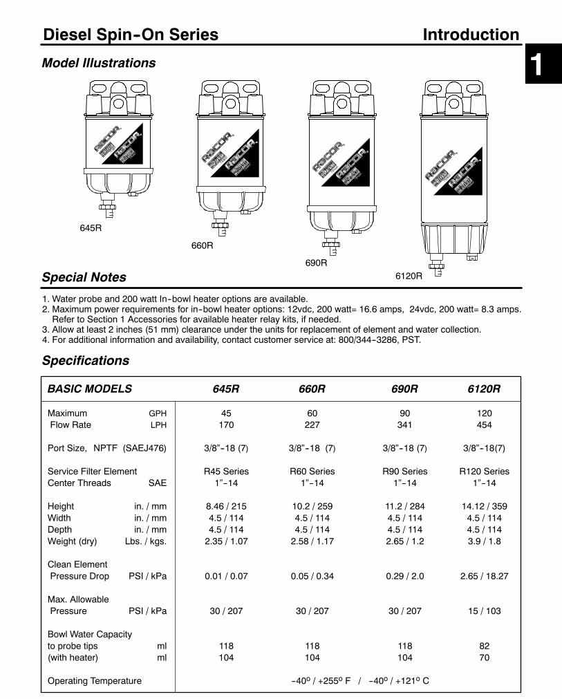
Model Illustrations
Special Notes
1. Water probe and 200 watt In--bowl heater options are available.2. Maximum power requirements for in--bowl heater options: 12vdc, 200 watt= 16.6 amps, 24vdc, 200 watt= 8.3 amps.Refer to Section 1 Accessories for available heater relay kits, if needed.
3. Allow at least 2 inches (51 mm) clearance under the units for replacement of element and water collection.4. For additional information and availability, contact customer service at: 800/344--3286, PST.
645R
660R
690R
1Introduction
6120R
Specifications
BASIC MODELS 645R 660R 690R 6120R
Maximum GPH 45 60 90 120Flow Rate LPH 170 227 341 454
Port Size, NPTF (SAEJ476) 3/8”--18 (7) 3/8”--18 (7) 3/8”--18 (7) 3/8”--18(7)
Service Filter Element R45 Series R60 Series R90 Series R120 SeriesCenter Threads SAE 1”--14 1”--14 1”--14 1”--14
Height in. / mm 8.46 / 215 10.2 / 259 11.2 / 284 14.12 / 359Width in. / mm 4.5 / 114 4.5 / 114 4.5 / 114 4.5 / 114Depth in. / mm 4.5 / 114 4.5 / 114 4.5 / 114 4.5 / 114Weight (dry) Lbs. / kgs. 2.35 / 1.07 2.58 / 1.17 2.65 / 1.2 3.9 / 1.8
Clean ElementPressure Drop PSI / kPa 0.01 / 0.07 0.05 / 0.34 0.29 / 2.0 2.65 / 18.27
Max. AllowablePressure PSI / kPa 30 / 207 30 / 207 30 / 207 15 / 103
Bowl Water Capacityto probe tips ml 118 118 118 82(with heater) ml 104 104 104 70
Operating Temperature --40o / +255o F / --40o / +121o C

26
Diesel Spin--On Series
How to Order --The example below illustrates how the part numbers are constructed.Note: to order a unit with metric ports, specify an asterisk (*) in front of the part number.
Models 645R, 660R, 690R, 6120R
645R = 45 GPH
660R = 60 GPH
690R = 90 GPH
6120R=120 GPH
Performance Graphs
0
25
50
75
100
0 50 100 150
SAE J1839 Water Separation
PercentEfficient
Time (Minutes)
Mounting Hole Pattern --Refer to section introduction page for filter dimensions.
Replacement Service Elements --Service elements include filter seals.
Model Final Filtration Secondary Filtration Primary Filtration*2 Micron 10 Micron 30 Micron
645R R45S R45T R45P660R R60S R60T R60P690R R90S R90T R90P6120R R120S R120T R120P
*A secondary/final filter is required downstream.
0.00.20.40.60.81.0
0 30 60 90 120
SAE J905 Fuel Flow Restriction*PSI X 2.036 = inHg. / PSI X 6.895 = kPa
Flow (GPH)
PSI*
SAE J905 Solids Capacity(using: SOFTC--2A; 10 mic.Elements)
Grams
PSI*
--These results are from controlled laboratory tests. Field results may vary.
SPECIFICATIONS are found on 600 Diesel Spin-On Series introduction page.
Water Probe:1
Add ’P’for an in--bowlwater probe.(Omit if not desired).
200 watt In--bowlElectric Heater:2
’12’ for 12 vdc’24’ for 24 vdc(Omit if not desired).
Element FiltrationRating. Specify:2 for 2 micron10 for 10 micron30 for 30 micron
0
2
4
6
8
0 100 200 300 400 500
6120660645645 660 690 6120
645R P 12 2
1 Must be used with Water Detection Kit. See Accessories Section.2 Recommended for use with Racor Heater Relay Kit. See Accessories Section.
690
All models
.45”(11 mm)
Not to Scale
690R shown
3/8” (10 mm) diameterclearance for fasteners.
Head top view.4 Inlet/ 3 Outlet fuel ports are:3/8”--18 NPTF (SAE J476)
2.00 to 2.25”(51 mm to 57 mm)
Optional HeaterFeed--thru / Connector
Optional Water Probe /Connector
Inlet
Outlet Outlet
Inlet
Inlet

27
Models 645R, 660R, 690R, 6120RDiesel Spin--On SeriesFIGURE 1. 600 Series. The circled number corresponds to the item number shown in the parts list below.
Item/Part No. Description Case Qty.1 RK22098 Beige Mounting Head, 3/8”--18 NPTF 1
RK22423 Mounting Head, 16 mm X 1.5 metric ports 12 01SP--6S Metal Plug, 3/8” NPTF 13 R45S 645 Service Element, 2 micron 12
R45T 645 Service Element, 10 micron 12R45P 645 Service Element, 30 micron 12R60S 660 Service Element, 2 micron 12R60T 660 Service Element, 10 micron 12R60P 660 Service Element, 30 micron 12R90S 690 Service Element, 2 micron 6R90T 690 Service Element, 10 micron 6R90P 690 Service Element, 30 micron 6R120S 6120 Service Element, 2 micron 6R120T 6120 Service Element, 10 micron 6R120P 6120 Service Element, 30 micron 6
5 RK22333 Bowl Bevel--cut Gasket (#22333) 16 RK20126 Water Probe Port Plug (1/2”SAE) 17 RK309641 Water Probe (1/2” SAE) & Connector 18 RK22323 Heater Connector 19 RK30476 Bowl Self--venting Drain Valve Assembly 110 RK21113--13--11 Bowl w/Drain &Wtr.Probe Port Plug (1/2” SAE) 1
RK22616--012 Same as above but with 12vdc Heater 1RK22616--022 Same as above but with 24vdc Heater 122249 Installation Instructions, 645, 660 & 69022506 Installation Instructions, 6120 only
BOWL COMPONENTS PRIOR TO MAY, 19976 RK11--1679 Water Probe Port Plug (9/16”SAE) 1
RK211451 Water Probe Only (9/16”SAE) 1RK21199 Water Probe Connector 1
7 RK223711 Water Probe (9/16”SAE) & Connector 19 RK22329 Bowl Drain Valve Assembly (not shown) 110 RK21113--13 Bowl w/Drain valve and probe (9/16”SAE) 1
MODEL 6120R BOWL PARTS
11 30965 Bowl Gasket (formerly O--ring #30062) 1012 RK20126 Water Probe Port Plug (1/2”SAE) 113 RK309641 Water Probe (1/2” SAE) & Connector 114 RK30876 Heater 2--pole Connector Kit 115 RK30476 Bowl Self--venting Drain Valve Assembly 1
RK30058 Drain Valve with Seals (not shown) 116 RK30063 Bowl w/Drain & Probe Port Plug (1/2”SAE) 1
RK309002 Same as above but with 12vdc Heater 1RK309252 Same as above but with 24vdc Heater 1
1 Water probe must be used with a Water Detection Kit.Note: Check threads before ordering. Two different sizes wereavailable on bowl designs prior to May, 1997.
2 In--bowl heater may require a Heater Relay Kit. Power requirements(maximum) are: 12 vdc = 16.6 amps, 24 vdc = 8.3 amps.
See Accessories Section.
2
6
1215
14
9
16
1
11
Not shown.On underside
of head
Optional HeaterFeed--thru
7
1
3
5
4
10
8
13

48
On and Off Highway Turbine Series
Selection Information
GeneralRacor Turbine Series Fuel Filter/Water Separators have been protecting engines fromwater, dirt, foulants andother contaminants for over 30 years using a patented three--stage process:1. Separation. The turbine centrifuge separates solids and ’free’ water through centrifugal action.
Although the turbine has no moving parts, over 30% of the contaminants are removed here.2. Coalescing. Smaller water droplets and solids coalesce on the specially designed conical baffle and fall
to the collection bowl.3. Filtration. Engines benefit from near 100% water separation and fuel filtration with Racor’s proprietary
Aquabloct water repelling media.The units are designed for installation on the suction (vacuum) side of the fuel transfer pump for best efficiencybut may be installed on the pressure side up to 15 PSI.
Filters:High--capacity Aquabloct replaceable cartridge elements stopwater and remove solid contamination and areavailable in 2, 10 or 30 micron. Equipment owners can specify their filtration needs based on application, fuelquality, operating climates and maintenance schedules.A 30 micron filter (or primary filter) is used to filter raw fuel (or poor quality fuel) before it can be further filteredby finer medias such as a 10 or 2 micron.A 10 micron filter (or secondary and even final) is used to filter fuel which is known to be of good quality.A 2 micron filter (or final filter) is the finest filtration available and is the last filter used prior to engine ingestion.
A simple rule to remember is the finer the filtration, the more frequent the filter change. (Carry extra filters withyour equipment).
Collection Bowls:The see--thru bowls used with these models won’t discolor from alcohol, additives or UV light and have aleak--proof, self--venting drain for easy service. Water and contaminant levels can be seen easily at a glance.For gasoline or severe service in diesel applications, specify metal bowls, only. (See Marine section for unitswith metal bowls).
Options --Available for Diesel fuel systems only.Water Probe. All units may be ordered with an in--bowl water probe to alert the operator of a high--watercondition, evenwhile the equipment is operating. The bowl is thendrained ofwater at the earliest convenience.Note: A Racor Water Detection Module is needed to work with the probe. See Accessories.
Fuel Heater. These unitsmay be orderedwith an in--housing 300watt (500models: 150watt), thermostaticallycontrolled resistance heater. This design places the heat source below the element to maximize heat transfer.Note: An additional relay (or relay kit) may be needed to operate the fuel heater. See Accessories.
SELECTION1. Along with the information you obtained in SECTION 1, SELECTION (page 2), consider the following:
Are there any space limitations in the available location? The location should provide adequate overheadspace for removing the element and underneath space for draining off contaminants from the bowl.
2. What filtration rating is needed? 2, 10 or 30 micron?3. What options are needed? Water probe and/or an in--bowl heater?4. Can the engine be shut down for servicing?
For engine(s) that cannot be shut--down if servicing becomes necessary, specify only FGV or FGX units.
Using this information, select a unit from the following page for your application.For additional information, call your Racor dealer or call Racor customer service at (209) 521--7860or (800) 344--3286, 6:00 AM to 5:00 PM, Pacific Time, or e--mail us from our website,www.parker.com/racor.
Selection
49
Turbine Series
500FG 500FGSS
Specifications
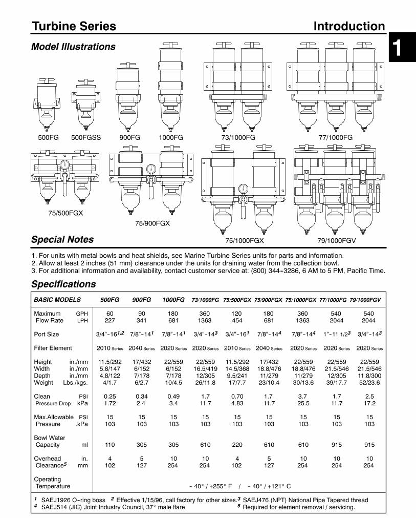
BASIC MODELS 500FG 900FG 1000FG 73/1000FG 75/500FGX 75/900FGX 75/1000FGX 77/1000FG 79/1000FGV
Maximum GPH 60 90 180 360 120 180 360 540 540Flow Rate LPH 227 341 681 1363 454 681 1363 2044 2044
Port Size 3/4”--161,2 7/8”--141 7/8”--141 3/4”--143 3/4”--161 7/8”--144 7/8”--144 1”--11 1/23 3/4”--143
Filter Element 2010 Series 2040 Series 2020 Series 2020 Series 2010 Series 2040 Series 2020 Series 2020 Series 2020 Series
Height in./mm 11.5/292 17/432 22/559 22/559 11.5/292 17/432 22/559 22/559 22/559Width in./mm 5.8/147 6/152 6/152 16.5/419 14.5/368 18.8/476 18.8/476 21.5/546 21.5/546Depth in./mm 4.8/122 7/178 7/178 12/305 9.5/241 11/279 11/279 12/305 11.8/300Weight Lbs./kgs. 4/1.7 6/2.7 10/4.5 26/11.8 17/7.7 23/10.4 30/13.6 39/17.7 52/23.6
Clean PSI 0.25 0.34 0.49 1.7 0.70 1.7 3.7 1.7 2.5Pressure Drop kPa 1.72 2.4 3.4 11.7 4.83 11.7 25.5 11.7 17.2
Max.Allowable PSI 15 15 15 15 15 15 15 15 15Pressure .kPa 103 103 103 103 103 103 103 103 103
Bowl WaterCapacity ml 110 305 305 610 220 610 610 915 915
Overhead in. 4 5 10 10 4 5 10 10 10Clearance5 mm 102 127 254 254 102 127 254 254 254
OperatingTemperature -- 40_ / +255_ F / -- 40_ / +121_ C
1 SAEJ1926 O--ring boss 2 Effective 1/15/96, call factory for other sizes.3 SAEJ476 (NPT) National Pipe Tapered thread4 SAEJ514 (JIC) Joint Industry Council, 37_ male flare 5 Required for element removal / servicing.
Model Illustrations
Special Notes
1. For units with metal bowls and heat shields, see Marine Turbine Series units for parts and information.2. Allow at least 2 inches (51 mm) clearance under the units for draining water from the collection bowl.3. For additional information and availability, contact customer service at: (800) 344--3286, 6 AM to 5 PM, Pacific Time.
900FG 1000FG
75/500FGX
77/1000FG
75/900FGX
79/1000FGV
73/1000FG
75/1000FGX
1Introduction

50
Turbine Series
How to Order --The example below illustrates how the part numbers are constructed.Note -- to order a unit with metric threads, specify an asterisk (*) in front of the part number.
Model 500FG
500FG
Basic Model60 GPH.For metalbowl unitsee MarineTurbineSeries inSection Two.
12
150 watt ElectricHeater:2
Add:’12’ for 12 vdc
or’24’ for 24 vdc(Omit if notdesired).
SS
3--piecebracket:Add ’SS’for thisbracketoption.(Omit if notdesired).
10
Element FiltrationRating.Specify one:
’2’ for 2 micron
’10’ for 10 micronor
’30’ for 30 micron
P
1 Must be used with Water Detection Kit --See Accessories Section.2 Recommended for use with Racor Heater Relay Kit --See Accessories Section.
500FG
500FGSS
Performance Graphs
0
25
50
75
100
0 50 100 150
SAE J1839 Water Separation
PercentEfficient
Time (Minutes)
3.12”(79 mm)
1.50”(38 mm)
5.25”(133 mm)
3/8” (10mm) diameterclearance for fasteners.
5.40”(137 mm)
3/8” (10mm) diameterclearance for fasteners.
3.60”(91 mm)
6.10”(155 mm)
6.25”(159 mm)
INLET
Dimension / Mounting Hole Patterns
500FG 500FG S/S
Replacement Service Elements --For all Model 500 SeriesSERVICE ELEMENT INCLUDES LID SEAL & T--HANDLE O--RING.
2010SM-OR 2 Micron (Brown end caps)Recommended for Final /Secondary Filtration
2010TM-OR 10 Micron (Blue end caps)Recommended for Primary or Secondary Filtration
2010PM-OR 30 Micron (Red end caps)Recommended for Primary Filtration Only.( A secondary/final filter is required downstream ).
0.00.10.20.30.40.5
0 15 30 45 60
SAE J905 Fuel Flow Restriction*PSI X 2.036 = inHg. / PSI X 6.895 = kPa
Flow (GPH)
PSI*
0
2
4
6
8
0 10 20 30 40 50 60 70
SAE J905 Solids Capacity(using SOFTC--2A: 2010TM Element)
Grams
PSI*
These results are from controlled laboratory tests. Field results may vary.
SPECIFICATIONS are found on Turbine Series introduction page.
Standard Fuel Ports:3/4”--16 UNF with O--ringBoss Seal (SAE J1926)
Water Probe.1
Add ’P’ for an
in--bowl water
probe.
(Omit if not
desired).

51
Model 500FG
Item/Part No. Description Case Qty.1 RK11888 T--handle (FG/FGSS only), thread is 9/16”--18 SAE 1
11350 T--handle O--ring (FG) 10
11003 T--handle Nylon Gasket (FE/FF --not shown) 10
2 RK15078 Lid (FG/FGSS/FGMSS) 1
15005 Lid Gasket (All models) 10
3 RK15377--01 Body, 3/4”--16 UNF fuel ports (FG, effective 1/15/96) 1
RK15377--02 Body, 16M X 1.5 fuel ports (metric, effective 1/15/96) 1
RK15377--03 Body, 3/8”--18 NPTF fuel ports (effective 1/15/96) 1
RK15082 Body, 9/16”--18 UNF fuel ports (FF/FG) 1
4 2010SM--OR 2 Micron Element w/ Seals 12
2010TM--OR 10 Micron Element w/ Seals 12
2010PM--OR 30 Micron Element w/ Seals 12
5 RK15310--01 Heater, 12 vdc, 150 watt (for use with body feed--thru) 1
RK15383--011 Heater, 12 vdc, 150 watt with body feed--thru (item 8) 1
RK15310--02 Heater, 24 vdc, 150 watt (for use with body feed--thru) 1
RK15383--021 Heater, 24 vdc, 150 watt with body feed--thru (item 8) 1
HEATER RETROFIT KITS FOR OLDER UNITS: SEE ACCESSORIES
6 RK15090 Mounting Bracket w/ Attached Bowl Ring (FG) 1
RK15035 Bowl Ring (FE/FF/FGSS --not shown) 1
7 15374 Bowl Gasket (supercedes 15009 O--ring --All models) 10
8 RK21067 Body Feed--thru Assembly (for bodies with feed--thru port)1
(wire gauge = 14 AWG)
9 RK15013D Turbine Centrifuge / Conical Baffle (All models) 1
10 RK210692 Water Probe (for bowls with 1/2”--20 UNF port present) 1
RK20126 Water Probe Port Plug (plastic) 1
11 RK30488 Self--Venting Drain (FF/FG/FGSS, See Figure 2) 10
11040 Bowl Drain Fitting (FE/FF, See Figure 2) 10
RK11341 Bowl Drain Gasket Kit (11041 & 11340 --not shown) 10
12 RK15279 See--thru Bowl w/ Water Probe Port & Plug 1
RK15301 Metal Bowl with 1/4”NPT drain threads (FFM/FGMSS) 1
13 RK15010B Check Ball w/ Seal (All models) 1
14 RK15081--013 Phillips Head Capscrews 10--24 x 1” (4) 1
RK150813 Hex/Washer Head Capscrews 10--24 x 7/8” (4) 1
15 RK15079 Standard Return Tube 1
16 RK15300 Mounting Bracket, 3--piece Clamp Type (FGSS/FGM) 1
17 RK15211 Assembly Seal Service Kit, All models (not shown) 1
RK11746 Seal Service Kit for Drain #11780 (See Figure 2) 1
15332 Installation Instructions, 500 Series
1 Filter body must have port next to fuel Inlet for heater feed--thru installation.
In--filter heater kits may require a Heater Relay Kit. Power requirements are
(maximum) : 12vdc = 12.5 amps, 24vdc = 6.3 amps.2 Water probe must be used with a Water Detection Kit.3 Models built prior to 2/96 use RK15081--01, after 2/96 use RK15081.
( The fuel ports have a 1 1/4” square boss on models made after 2/96 ).
See Accessories Section.
1
2
4
5
7
10
3
8
Turbine Series
FIGURE 1. 500 Series Cutaway View. The circled number corresponds to the item number shown below.
6
14
117804 30488(Standard)
11040/110424
15
1
9
12
11
13
16
FIGURE 2. Drain valve configurations.( 4Replace with 30488 drain valve )
5/16”

52
Turbine Series Model 900FG
Basic Model90 GPH.For metal bowlunit see MarineTurbine Seriesin Section Two.
Element FiltrationRating.Specify one:’2’ for 2 micron’10’ for 10 micron
or’30’ for 30 micron
Water Probe.1
Add ’P’ for anin--bowl waterprobe. (Omit ifnot desired).
1 Must be used with Water Detection Kit --See Accessories Section.2 May require the use of a Relay Kit --See Accessories Section.
Performance Graphs
0
25
50
75
100
0 50 100 150
SAE J1839 Water Separation
PercentEfficient
Time (Minutes)
2.75”(70 mm)
3/8” (10 mm) diameterclearance for fasteners.
4.50”(114 mm)
8.50”(216 mm)
Mounting Hole Pattern --Refer to Turbine Series introduction page for filter dimensions.
Not to scale.Shown withoptional WaterProbe.
Replacement Service Elements --For all Model 900 SeriesSERVICE ELEMENT INCLUDES LID SEAL & T--HANDLE O--RING.
2040SM-OR 2 Micron (Brown end caps)Recommended for Final /Secondary Filtration
2040TM-OR 10 Micron (Blue end caps)Recommended for Primary or Secondary Filtration
2040PM-OR 30 Micron (Red end caps)Recommended for Primary Filtration Only.( A secondary/final filter is required downstream ).
0.00.10.20.30.40.5
0 30 60 90
SAE J905 Fuel Flow Restriction*PSI X 2.036 = inHg. / PSI X 6.895 = kPa
Flow (GPH)
PSI*
0
2
4
6
8
0 100 200 300
SAE J905 Solids Capacity(using SOFTC--2A: 2040TM Element)
Grams
PSI*
--These results are from controlled laboratory tests. Field results may vary by application.
SPECIFICATIONS are found on Turbine Series introduction page.
900FG
Bracket height is adjustable from 2” (51 mm)to 5.50” (140 mm) above port center line.
Portcenterline
Standard Fuel Ports:7/8”--14 UNF withO--ring Boss Seal(SAEJ1926)
300 watt ElectricHeater.2 Specify:’312’ for 12 vdc
or’324’ for 24 vdc(Omit if not desired).
900FG P 312 10
How to Order --The example below illustrates how the part numbers are constructed.Note -- to order a unit with metric threads, specify an asterisk (*) in front of the part number.

53
Model 900FG
Item/Part No. Description Case Qty.1 RK11888 T--Handle, thread is 9/16”--18 SAE 1
11350 T--Handle O--ring 1011003 T--Handle Gasket, Nylon (FE/FF) 10
2 RK11005B Standard Lid 111007 Square--cut Gasket (Lid & Bowl ring) 10RK11005/A Lid, T--Handle and O--ring Kit 1RK11005B--02 Lid with Vent Port and Plug Kit (not shown) 1
3 RK19002 Outer Cylinder 14 2040SM--OR 2 Micron Element w/ Seals 12
2040TM--OR 10 Micron Element w/ Seals 122040PM--OR 30 Micron Element w/ Seals 12
5 RK11815--101 Body Clamp Bracket 16 RK11--1767--01 Heater, 12 vdc, 300 watt (for use with body feed--thru) 1
RK11--1800--011Heater, 12 vdc, 300 watt with body feed--thru (item 8) 1RK11--1767--02 Heater, 24 vdc, 300 watt (for use with body feed--thru) 1RK11--1800--021Heater, 24 vdc, 300 watt with body feed--thru (item 8) 1HEATER RETROFIT KITS FOR OLDER UNITS: SEE ACCESSORIES
7 11007 Square--cut Gasket (Lid & Bowl ring) 1011036 Bowl O--Ring (FE only--not shown) 10
8 RK21067 Body Feed--thru Assy. (for bodies with feed--thru port) 1(wire gauge = 14 AWG)
RK11--1679 Body Feed--thru Port Plug (plastic) 19 RK11026D Turbine Centrifuge / Conical Baffle 110 RK210692 Water Probe (for bowls with 1/2”--20 port) 1
RK20126 Water Probe Port Plug (plastic) 111 RK30488 Self--venting Drain (FF/FG/FGSS, See Figure 2) 10
RK11746 Seal Service Kit for Drain #11780 (See Figure 2) 112 11040 Bowl Drain Fitting (FE/FF, See Figure 2) 10
RK11341 Bowl Drain Gasket Kit (11041 & 11340, not shown) 1013 RK11--1606 See--thru Bowl with Water Probe Port & Plug 1
RK11734 Metal Bowl w/1/4”NPT Drain & Plug (FGM) 1RK11734--01 Same as above but with Water Probe Port & Plug 1
14 RK11028B Check Ball and Seal 1015 RK11542 Hex/Washer Head Capscrew, 1/4”--20 x 1” (4) 116 RK11037A Bowl Ring, 5” diameter (FF/FG) 117 RK11--1678 Body, 7/8”--14 SAE w/ Heater Feed--thru Port 1
RK11--1776--01 Body, (Same as above but includes return tube) 1RK11--1776--02 Body, Metric 22mm X 1.5 with Heater Port 1
18 RK19474 Return Tube w/ straight (body--end) threads 1RK19001 Return Tube w/ tapered pipe (body--end) threads 1
19 RK11--1404 Assembly Seal Service Kit (all models--not shown) 119472 Installation Instructions, 900/1000 Series
1 Filter body must have port next to fuel Inlet for heater feed--thru installation.In--filter heater may require a Heater Relay Kit. Power requirements are(maximum) : 12vdc = 25 amps, 24vdc = 12.5 amps.
2 Water probe must be used with a Water Detection Kit.See Accessories Section.
Turbine Series
FIGURE 1. 900 Series Cutaway View. The circled number corresponds to the item number shown below.
117804 30488(Standard)
11040/110424
11
2
3
4
5
6
7
11
8
9
10
13
15
14
17
18
12
16
FIGURE 2. Drain valve configurations.( 4Replace with 30488 drain valve )
5/16”
54
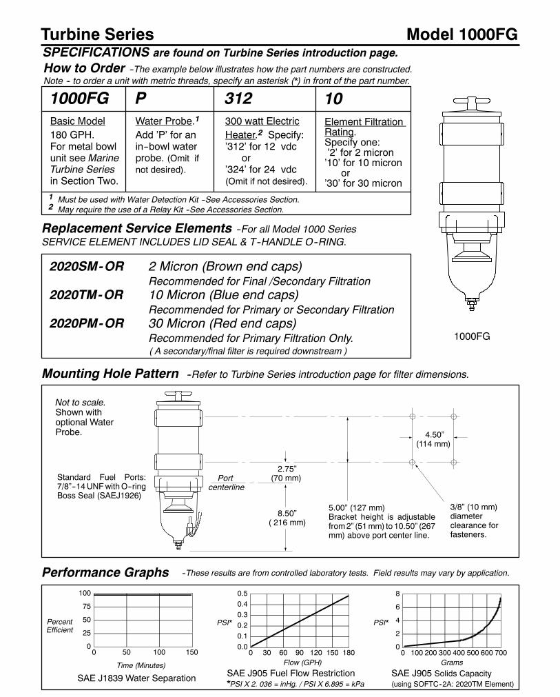
Turbine Series Model 1000FG
Performance Graphs
0
25
50
75
100
0 50 100 150
SAE J1839 Water Separation
PercentEfficient
Time (Minutes)
2.75”(70 mm)
3/8” (10 mm)diameterclearance forfasteners.
4.50”(114 mm)
8.50”( 216 mm)
Mounting Hole Pattern --Refer to Turbine Series introduction page for filter dimensions.
Not to scale.Shown withoptional WaterProbe.
Replacement Service Elements --For all Model 1000 SeriesSERVICE ELEMENT INCLUDES LID SEAL & T--HANDLE O--RING.
2020SM-OR 2 Micron (Brown end caps)Recommended for Final /Secondary Filtration
2020TM-OR 10 Micron (Blue end caps)Recommended for Primary or Secondary Filtration
2020PM-OR 30 Micron (Red end caps)Recommended for Primary Filtration Only.( A secondary/final filter is required downstream )
0.00.10.20.30.40.5
0 30 60 90 120 150 180
SAE J905 Fuel Flow Restriction*PSI X 2. 036 = inHg. / PSI X 6.895 = kPa
Flow (GPH)
PSI*
0
2
4
6
8
0 100 200 300 400 500 600 700
SAE J905 Solids Capacity(using SOFTC--2A: 2020TM Element)
Grams
--These results are from controlled laboratory tests. Field results may vary by application.
SPECIFICATIONS are found on Turbine Series introduction page.
1000FG
5.00” (127 mm)Bracket height is adjustablefrom2” (51mm) to 10.50” (267mm) above port center line.
Portcenterline
PSI*
Standard Fuel Ports:7/8”--14UNFwithO--ringBoss Seal (SAEJ1926)
1000FGBasic Model180 GPH.For metal bowlunit see MarineTurbine Seriesin Section Two.
PWater Probe.1
Add ’P’ for anin--bowl waterprobe. (Omit ifnot desired).
1 Must be used with Water Detection Kit --See Accessories Section.2 May require the use of a Relay Kit --See Accessories Section.
312300 watt ElectricHeater.2 Specify:’312’ for 12 vdc
or’324’ for 24 vdc(Omit if not desired).
10Element FiltrationRating.Specify one:’2’ for 2 micron’10’ for 10 micron
or’30’ for 30 micron
How to Order --The example below illustrates how the part numbers are constructed.Note -- to order a unit with metric threads, specify an asterisk (*) in front of the part number.

55
Model 1000FG
Item/Part No. Description Case Qty.1 RK11888 T--Handle, thread is 9/16”--18 SAE 1
11350 T--Handle O--ring 1011003 T--Handle Gasket, Nylon (FE/FF) 10
2 RK11005B Standard Lid 111007 Square--cut Gasket (Lid & Bowl ring) 10RK11005/A Lid, T--Handle and O--ring Kit 1RK11005B--02 Lid with Vent Port and Plug Kit (not shown) 1
3 RK11021 Outer Cylinder 14 2020SM--OR 2 Micron Element w/ Seals 12
2020TM--OR 10 Micron Element w/ Seals 122020PM--OR 30 Micron Element w/ Seals 12
5 RK11815--101 Body Clamp Bracket 16 RK11--1767--01 Heater, 12 vdc, 300 watt (for use with body feed--thru) 1
RK11--1800--011Heater, 12 vdc, 300 watt with body feed--thru (item 8) 1RK11--1767--02 Heater, 24 vdc, 300 watt (for use with body feed--thru) 1RK11--1800--021Heater, 24 vdc, 300 watt with body feed--thru (item 8) 1HEATER RETROFIT KITS FOR OLDER UNITS: SEE ACCESSORIES
7 11007 Square--cut Gasket (Lid & Bowl ring) 1011036 Bowl O--Ring (FE only--not shown) 10
8 RK21067 Body Feed--thru Assy. (for bodies with feed--thru port) 1(wire gauge = 14 AWG)
RK11--1679 Body Feed--thru Port Plug (plastic) 19 RK11026D Turbine Centrifuge / Conical Baffle 110 RK210692 Water Probe (for bowls with 1/2”--20 port) 1
RK20126 Water Probe Port Plug (plastic) 111 RK30488 Self--venting Drain (FF/FG/FGSS, See Figure 2) 10
RK11746 Seal Service Kit for Drain #11780 (See Figure 2) 112 11040 Bowl Drain Fitting (FE/FF, See Figure 2) 10
RK11341 Bowl Drain Gasket Kit (11041 & 11340, not shown) 1013 RK11--1606 See--thru Bowl with Water Probe Port & Plug 1
RK11734 Metal Bowl w/1/4”NPT Drain & Plug (FGM) 1RK11734--01 Same as above but with Water Probe Port & Plug 1
14 RK11028B Check Ball and Seal 1015 RK11542 Hex/Washer Head Capscrew, 1/4”--20 x 1” (4) 116 RK11037A Bowl Ring, 5” diameter (FF/FG) 117 RK11--1678 Body, 7/8”--14 SAE w/ Heater Feed--thru Port 118 RK11--1775 Return Tube w/ straight (body--end) threads 1
RK11008 Return Tube w/ tapered pipe (body--end) threads 119 RK11--1404 Assembly Seal Service Kit (all models--not shown) 1
19472 Installation Instructions, 900/1000 Series
1 Filter body must have port next to fuel Inlet for heater feed--thru installation.In--filter heater may require a Heater Relay Kit. Power requirements are(maximum) : 12vdc = 25 amps, 24vdc = 12.5 amps.
2 Water probe must be used with a Water Detection Kit.See Accessories Section.
Turbine Series
FIGURE 1. 1000 Series Cutaway View. The circled number corresponds to the item number shown below.
117804 30488(Standard)
11040/110424
11
2
3
4
5
6
7
11
8
9
10
13
15
14
17
18
12
16
FIGURE 2. Drain valve configurations.( 4Replace with 30488 drain valve )
5/16”

56
Turbine Series
How to Order --The example below illustrates how the part numbers are constructed.
Model 73/1000FG
Basic Model360 GPHFor metal bowl unitsee Marine TurbineSeries in SectionTwo.
Element FiltrationRating.Specify one:’2’ for 2 micron,’10’ for 10 micronor
’30’ for 30 micron
Water Probes.1Add ’P’ forin--bowl waterprobes. (Omitif not desired).
1 Must be used with Water Detection Kit --See Accessories Section.2 Must be used with a Relay Kit --See Accessories Section.
Performance Graphs -- These results are from controlled laboratory tests. Field results may vary by application.
0
25
50
75
100
0 50 100 150
SAE J1839 Water Separation
PercentEfficient
Time (Minutes)
4.00”(102 mm)
3/8” (10 mm) diameterclearance for fasteners.
15.00”(381 mm)12.50”
(318 mm)
Mounting Hole Pattern --Refer to Turbine Series introduction page for filter dimensions.
Replacement Service Elements --For all Model 73/1000 Series
SERVICE ELEMENT INCLUDES LID SEAL & T--HANDLE O--RING. Order two (2) per unit.
2020SM-OR 2 Micron (Brown end caps)Recommended for Final /Secondary Filtration
2020TM-OR 10 Micron (Blue end caps)Recommended for Primary or Secondary Filtration
2020PM-OR 30 Micron (Red end caps)Recommended for Primary Filtration* Only.*A secondary/final filter is required downstream.
0.0
0.5
1.0
1.5
2.0
0 60 120 180 240 300 360
SAE J905 Fuel Flow Restriction*PSI X 2.036 = inHg. / PSI X 6.895 = kPa
Flow (GPH)
PSI*
0
2
4
6
8
0 250 500 750 10001250
SAE J905 Solids Capacity(using SOFTC--2A; 2020TM Element)
Grams
SPECIFICATIONS are found on Turbine Series introduction page.
73/1000FG
INLET
5.75”(146 mm)
OUTLET
Not to scale.Shown withoptional WaterProbes.
PSI*
300 watt Electric
Heaters.2 Specify:
’312’ for 12 vdc or
’324’ for 24 vdc.
(Omit if not desired).
Standard FuelInlet / Outlet:3/4”--14 NPT
73/1000FG P 312 10

57
Model 73/1000FG
Item Part No. Description Case Qty.
1 1000FG Shell. Refer to Model 1000FG
for a complete parts list.
2 11065 Dual Bracket 1
3 RK11815--101 Clamp Bracket Assembly 1
4 RK11892 3/4” Inlet & Outlet Manifolds 1
5 11071 Straight Fitting 1
11--1825 Installation Instructions, 73/1000FG
For Heater Relay Kits, Water Detection Kits and Manifold
Conversion Kits, see the Accessories Section.
For parts not listed, call Racor customer service: (800) 344--3286.
Turbine Series
FIGURE 1. 73/1000 Series. The circled number corresponds to the item number shown in the parts list below.
73/1000FGP Model shown
4
5
1
3
2
1

58
Turbine Series
How to Order --The example below illustrates how the part numbers are constructed.
Model 75/500FGX
Performance Graphs
0
25
50
75
100
0 50 100 150
SAE J1839 Water Separation
PercentEfficient
Time (Minutes)
3/8” (10 mm) diameterclearance for fasteners.
12.68”(322 mm)
5.50”(140 mm)
Mounting Hole Pattern --Refer to Turbine Series introduction page for filter dimensions.
Not to scale.Shown withoptionalWaterProbes.
Replacement Service Elements --For all Model 75/500FGX Series
SERVICE ELEMENT INCLUDES LID SEAL & T--HANDLE O--RING. Order two (2) per unit.
2010SM-OR 2 Micron (Brown end caps)Recommended for Final /Secondary Filtration
2010TM-OR 10 Micron (Blue end caps)Recommended for Primary or Secondary Filtration
2010PM-OR 30 Micron (Red end caps)Recommended for Primary Filtration* Only.*A secondary/final filter is required downstream.
0.0
0.5
1.0
1.5
2.0
0 30 60 90 120
SAE J905 Fuel Flow Restriction*PSI X 2.036 = inHg. / PSI X 6.895 = kPa
Flow (GPH)
PSI*
0
2
4
6
8
0 20 40 60 80 100 120 140
SAE J905 Solids Capacity(using SOFTC--2A; 2010TM Element)
Grams
PSI*
--These results are from controlled laboratory tests. Field results may vary by application.
SPECIFICATIONS are found on Turbine Series introduction page.
75/500FGX
5.00”(127 mm)
6.34”(161 mm)
Inlet / Outleton valve underside:
3/4”--16UNF (SAEJ1926)
Basic Model120 GPHFor metal bowl unitsee Marine TurbineSeries in SectionTwo.
Water Probes.1Add ’P’ forin--bowl waterprobes. (Omitif not desired).
1 Must be used with Water Detection Kit --See Accessories Section.2 Must be used with a Relay Kit --See Accessories Section.
150 watt Electric
Heaters.2 Specify:
’12’ for 12 vdc or
’24’ for 24 vdc.
(Omit if not desired).
75/500FGX P 12 10Element FiltrationRating.Specify one:2 for 2 micron,10 for 10 micronor
30 for 30 micron

59
Model 75/500FGX
Item Part No. Description Case Qty.
1 500FGSS Shell. Refer to Model 500FGSS
for a complete parts list
2 RK15329 Main Bracket, (Shown, for one--pc.brkts) 1
RK15329--01 Main Bracket, (Accommodates three
piece body clamp brackets, see item 6) 1
3 RK19476 Gauge Assembly 1
4 RK15378 Body Clamp Bracket, One--Piece 1
5 RK15344 Rigid Tubing & Fittings Kit 1
6 RK15300 Body Clamp Bracket, Three--Piece 1
7 RK15321 Valve Assembly 1
RK15389 Valve Service Kit 1
15349 Installation Instructions
For Fuel Port Adapter Fittings, Heater Relay Kits, Water Detection
Kits and Manifold Conversion Kits, see the Accessories Section.
For parts not listed, call Racor customer service: 800/344--3286.
Turbine Series
FIGURE 1. 75/500 Series. The circled number corresponds to the item number shown in the parts list below.
75/500FGXPModel shown
5
1 2
7
4
3
1
6
RK15300 Three--piece bracket
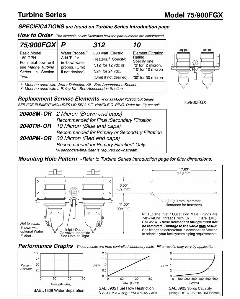
60
Turbine Series
How to Order --The example below illustrates how the part numbers are constructed.
Model 75/900FGX
Performance Graphs --These results are from controlled laboratory tests. Filter results may vary by application.
0
25
50
75
100
0 50 100 150
SAE J1839 Water Separation
PercentEfficient
Time (Minutes)
3/8” (10 mm) diameterclearance for fasteners.11.50”
(292 mm)
Mounting Hole Pattern --Refer to Turbine Series introduction page for filter dimensions.
Replacement Service Elements --For all Model 75/900FGX Series
SERVICE ELEMENT INCLUDES LID SEAL & T--HANDLE O--RING. Order two (2) per unit.
2040SM-OR 2 Micron (Brown end caps)Recommended for Final /Secondary Filtration
2040TM-OR 10 Micron (Blue end caps)Recommended for Primary or Secondary Filtration
2040PM-OR 30 Micron (Red end caps)Recommended for Primary Filtration* Only.*A secondary/final filter is required downstream.
0.0
0.5
1.0
1.5
2.0
0 60 120 180
SAE J905 Fuel Flow Restriction*PSI X 2.036 = inHg. / PSI X 6.895 = kPa
Flow (GPH)
PSI*
0
2
4
6
8
0 100 200 300 400 500 600
SAE J905 Solids Capacity(using SOFTC--2A; 2040TM Element)
Grams
PSI*
SPECIFICATIONS are found on Turbine Series introduction page.
75/900FGX
Inlet / Outlet:On valve underside.See Note at Right.
3.50”(89 mm)
17.63”(448 mm)
Not to scale.Shown withoptional WaterProbes.
Basic Model180 GPHFor metal bowl unitsee Marine TurbineSeries in SectionTwo.
Water Probes.1Add ’P’ forin--bowl waterprobes. (Omitif not desired).
1 Must be used with Water Detection Kit --See Accessories Section.2 Must be used with a Relay Kit --See Accessories Section.
300 watt Electric
Heaters.2 Specify:
’312’ for 12 vdc or
’324’ for 24 vdc.
(Omit if not desired).
75/900FGX P 312 10Element FiltrationRating.Specify one:’2’ for 2 micron,’10’ for 10 micronor
’30’ for 30 micron
NOTE: The Inlet / Outlet Port Male Fittings are7/8”--14UNF threads with 37_ Flare (JIC);SAEJ514. These permanent fittings must notbe removed. Damage to the valve may result.See fittingsselectionchart inAccessoriesSectionto adapt to your fuel system piping requirements.
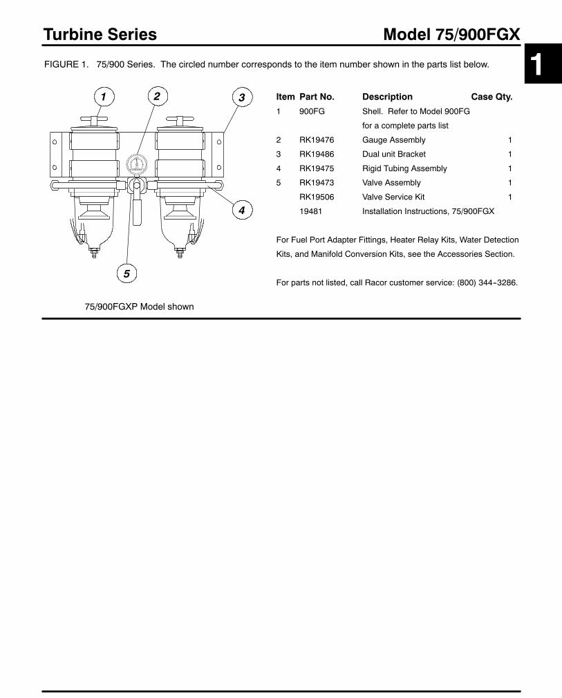
61
Model 75/900FGX
Item Part No. Description Case Qty.
1 900FG Shell. Refer to Model 900FG
for a complete parts list
2 RK19476 Gauge Assembly 1
3 RK19486 Dual unit Bracket 1
4 RK19475 Rigid Tubing Assembly 1
5 RK19473 Valve Assembly 1
RK19506 Valve Service Kit 1
19481 Installation Instructions, 75/900FGX
For Fuel Port Adapter Fittings, Heater Relay Kits, Water Detection
Kits, and Manifold Conversion Kits, see the Accessories Section.
For parts not listed, call Racor customer service: (800) 344--3286.
Turbine Series
FIGURE 1. 75/900 Series. The circled number corresponds to the item number shown in the parts list below.
75/900FGXP Model shown
4
1
5
2 3
1

62
Turbine Series
How to Order --The example below illustrates how the part numbers are constructed.
Model 75/1000FGX
Performance Graphs --These results are from controlled laboratory tests. Field results may vary by application.
0
25
50
75
100
0 50 100 150
SAE J1839 Water Separation
PercentEfficient
Time (Minutes)
3/8” (10 mm) diameterclearance for fasteners.
10.50”(267 mm)
Mounting Hole Pattern --Refer to Turbine Series introduction page for filter dimensions.
Replacement Service Elements --For all Model 75/1000FGX Series
SERVICE ELEMENT INCLUDES LID SEAL & T--HANDLE O--RING. Order two (2) per unit.
2020SM-OR 2 Micron (Brown end caps)Recommended for Final /Secondary Filtration
2020TM-OR 10 Micron (Blue end caps)Recommended for Primary or Secondary Filtration
2020PM-OR 30 Micron (Red end caps)Recommended for Primary Filtration* Only.*A secondary/final filter is required downstream.
012345
0 60 120 180 240 300 360
SAE J905 Fuel Flow Restriction*PSI X 2.036 = inHg. / PSI X 6.895 = kPa
Flow (GPH)
PSI*
0
2
4
6
8
0 300 600 900 1200
SAE J905 Solids Capacity(using SOFTC--2A; 2020TM Element)
Grams
PSI*
SPECIFICATIONS are found on Turbine Series introduction page.
75/1000FGX
3.88”(98 mm)
17.63”(448 mm)
7.75”(279 mm)
Not to scale.Shown withoptionalWaterProbes.
Basic Model360 GPHFor metal bowl unitsee Marine TurbineSeries in SectionTwo.
Water Probes.1Add ’P’ forin--bowl waterprobes. (Omitif not desired).
1 Must be used with Water Detection Kit --See Accessories Section.2 Must be used with a Relay Kit --See Accessories Section.
300 watt Electric
Heaters.2 Specify:
’312’ for 12 vdc or
’324’ for 24 vdc.
(Omit if not desired).
75/1000FGX P 312 10Element FiltrationRating.Specify one:’2’ for 2 micron,’10’ for 10 micronor
’30’ for 30 micron
NOTE: The Inlet / Outlet Port Male Fittings are7/8”--14UNF threads with 37_ Flare (JIC);SAEJ514. These permanent fittings must notbe removed. Damage to the valve may result.See fittingsselectionchart inAccessoriesSectionto adapt to your fuel system piping requirements.
Inlet / Outlet:On valve underside.See Note at Right.
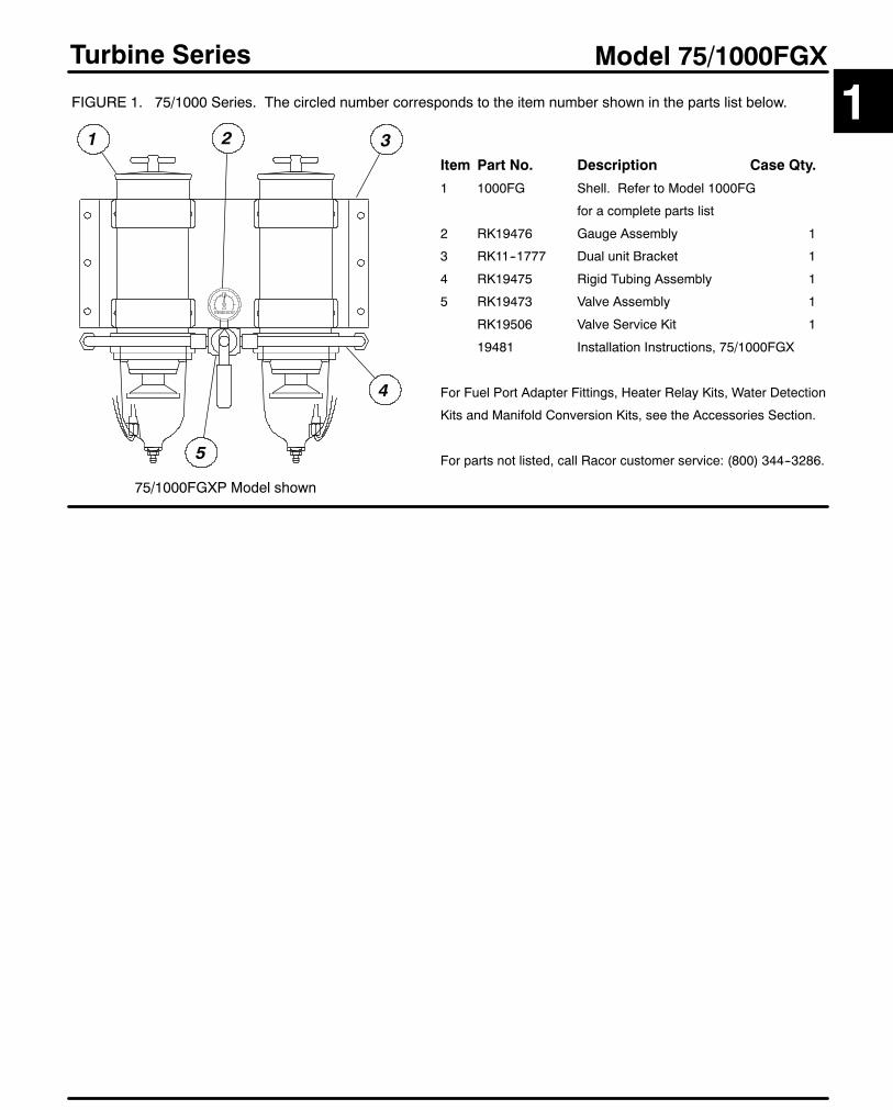
63
Model 75/1000FGX
Item Part No. Description Case Qty.
1 1000FG Shell. Refer to Model 1000FG
for a complete parts list
2 RK19476 Gauge Assembly 1
3 RK11--1777 Dual unit Bracket 1
4 RK19475 Rigid Tubing Assembly 1
5 RK19473 Valve Assembly 1
RK19506 Valve Service Kit 1
19481 Installation Instructions, 75/1000FGX
For Fuel Port Adapter Fittings, Heater Relay Kits, Water Detection
Kits and Manifold Conversion Kits, see the Accessories Section.
For parts not listed, call Racor customer service: (800) 344--3286.
Turbine Series
FIGURE 1. 75/1000 Series. The circled number corresponds to the item number shown in the parts list below.
75/1000FGXP Model shown
4
1
5
2 3
1

64
Turbine Series
How to Order --The example below illustrates how the part numbers are constructed.
Model 77/1000FG
Performance Graphs --These results are from controlled laboratory tests. Field results may vary by application.
0
25
50
75
100
0 50 100 150
SAE J1839 Water Separation
PercentEfficient
Time (Minutes)
3/8” (10 mm) diameterclearance for fasteners.
12.50”(318 mm)
Mounting Hole Pattern --Refer to Turbine Series introduction page for filter dimensions.
Replacement Service Elements --For all Model 77/1000 Series
SERVICE ELEMENT INCLUDES LID SEAL & T--HANDLE O--RING. Order three (3) per unit.
2020SM-OR 2 Micron (Brown end caps)Recommended for Final /Secondary Filtration
2020TM-OR 10 Micron (Blue end caps)Recommended for Primary or Secondary Filtration
2020PM-OR 30 Micron (Red end caps)Recommended for Primary Filtration* Only.*A secondary/final filter is required downstream.
0.0
0.5
1.0
1.5
2.0
0 180 360 540
SAE J905 Fuel Flow Restriction*PSI X 2.036 = inHg. / PSI X 6.895 = kPa
Flow (GPH)
PSI*
0
2
4
6
8
0 500 1000 1500 2000
SAE J905 Solids Capacity(using SOFTC--2A; 2020TM Element)
Grams
PSI*
SPECIFICATIONS are found on Turbine Series introduction page.
77/1000FG
INLET
4.00”(102 mm)
19.75”(502 mm)
5.75”(146 mm)
Not to scale.Shown withoptionalWaterprobes.
Inlet / Outlet:1”--11 1/2 NPT
OUTLET
Basic Model540 GPHFor metal bowl unitsee Marine TurbineSeries in SectionTwo.
Element FiltrationRating.Specify one:’2’ for 2 micron,’10’ for 10 micronor
’30’ for 30 micron
Water Probes.1Add ’P’ forin--bowl waterprobes. (Omitif not desired).
1 Must be used with Water Detection Kit --See Accessories Section.2 Must be used with a Relay Kit --See Accessories Section.
300 watt Electric
Heaters.2 Specify:
’312’ for 12 vdc or
’324’ for 24 vdc.
(Omit if not desired).
77/1000FG P 312 10
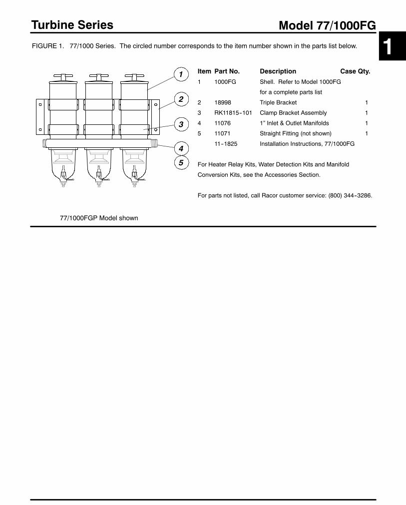
65
Model 77/1000FG
Item Part No. Description Case Qty.
1 1000FG Shell. Refer to Model 1000FG
for a complete parts list
2 18998 Triple Bracket 1
3 RK11815--101 Clamp Bracket Assembly 1
4 11076 1” Inlet & Outlet Manifolds 1
5 11071 Straight Fitting (not shown) 1
11--1825 Installation Instructions, 77/1000FG
For Heater Relay Kits, Water Detection Kits and Manifold
Conversion Kits, see the Accessories Section.
For parts not listed, call Racor customer service: (800) 344--3286.
Turbine Series
FIGURE 1. 77/1000 Series. The circled number corresponds to the item number shown in the parts list below.
77/1000FGP Model shown
3
4
5
2
1
1
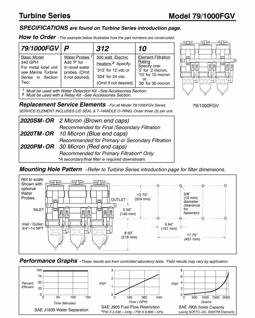
66
Turbine Series
How to Order --The example below illustrates how the part numbers are constructed.
Model 79/1000FGV
Performance Graphs --These results are from controlled laboratory tests. Field results may vary by application.
0
25
50
75
100
0 50 100 150
SAE J1839 Water Separation
PercentEfficient
Time (Minutes)
3/8”(10 mm)diameterclearanceforfasteners.
8.50”(216 mm)
Mounting Hole Pattern --Refer to Turbine Series introduction page for filter dimensions.
Replacement Service Elements --For all Model 79/1000FGV Series
SERVICE ELEMENT INCLUDES LID SEAL & T--HANDLE O--RING. Order three (3) per unit.
2020SM-OR 2 Micron (Brown end caps)Recommended for Final /Secondary Filtration
2020TM-OR 10 Micron (Blue end caps)Recommended for Primary or Secondary Filtration
2020PM-OR 30 Micron (Red end caps)Recommended for Primary Filtration* Only.*A secondary/final filter is required downstream.
0
1
2
3
0 180 360 540
SAE J905 Fuel Flow Restriction*PSI X 2.036 = inHg. / PSI X 6.895 = kPa
Flow ( GPH)
PSI*
0
2
4
6
8
0 500 1000 1500 2000
SAE J905 Solids Capacity(using SOFTC--2A; 2020TM Element)
Grams
PSI*
SPECIFICATIONS are found on Turbine Series introduction page.
79/1000FGV
INLET
5.94”(151 mm)
17.75”(451 mm)
12.75”(324 mm)OUTLET
5.50”(140 mm)
Not to scale.Shown withoptionalWaterProbes.
Inlet / Outlet:3/4”--14 NPT
Basic Model540 GPHFor metal bowl unitsee Marine TurbineSeries in SectionTwo.
Element FiltrationRating.Specify one:’2’ for 2 micron,’10’ for 10 micronor
’30’ for 30 micron
Water Probes.1Add ’P’ forin--bowl waterprobes. (Omitif not desired).
1 Must be used with Water Detection Kit --See Accessories Section.2 Must be used with a Relay Kit --See Accessories Section.
300 watt Electric
Heaters.2 Specify:
’312’ for 12 vdc or
’324’ for 24 vdc.
(Omit if not desired).
79/1000FGV P 312 10

67
Model 79/1000FGV
Item Part No. Description Case Qty.
1 1000FG Shell. Refer to Model 1000FG
for a complete parts list
2 11--1632 Triple Bracket 1
3 11895 Clamp Bracket 1
4 11--1761 ’U’ Bracket 1
5 19461 Outlet Manifold 1
6 RK11073 1/2” Ball Valve 1
7 11--1626 Formed Tubing Assembly 1
8 19460 Inlet Manifold 1
11--1821 Installation Instructions, 79/1000FGV
For Heater Relay Kits, Water Detection Kits and Manifold
Conversion Kits, see the Accessories Section.
For parts not listed, call Racor customer service: (800) 344--3286.
Turbine Series
FIGURE 1. 79/1000 Series. The circled number corresponds to the item number shown in the parts list below.
79/1000FGVP Model shown
5
6
1 2
7
3
8
4
1

68
Turbine SeriesIn-Depth Guide
Fuel Filter Troubleshooting:On new installations the unit must be filled with fuel and the fuel system must be adequately primed following the enginemanufacturer’s recommendation, if applicable. On existing installations difficulties are usually associatedwith improperpriming procedures or damage to the unit or fuel system. The result is either internal air suction or external fuel leakage.Correct external fuel leaks immediately. These conditionswill result in reduced engine performance such as: hard starting,stalling, reduced power, and other associated problems. Diagnosis should be in the following steps:1. Check fuel tank level and make sure any fuel delivery valves are in the position, as applicable.2. Ensure the T--handle, lid vent (if applicable), bowl fasteners, and fuel fittings are tight. The bowl drain must be closed.3. If the Racor element is new, check potential restriction at the fuel tank draw tube. An in--tank strainer may be plugged.4. Review some of the workings of the units below to possibly uncover other solutions.
How the unit works: Refer to the Turbine Series Selection page found at the beginning of this section.Correct Application: It is very important that the unit is not ’under specified’ for the application. The maximum fuel flowrating of the unit must not be exceeded. Doing so will reduce efficiency and de--gas (pull air from) the fuel. Refer to theTurbine Series Introduction page found at the beginning of this section for maximum flow rates.
Filter Elements: Replacement elements are available in 2, 10, and 30 micron ratings. Filtration needs are based onapplication, fuel quality, maintenance schedules, and operating climates. Refer to theTurbine SeriesSelection page foundat the beginning of this section for specifying the correct micron rating.A simple rule to remember: The finer the filtration, the more frequent the filter change. Carry extra filters with yourequipment. When clogged to the maximum capacity, elements will have a brown to black color or tar like contaminantsmay be present -- this is normal. An appearance of a multi--colored slime (which may have a foul odor) is an indicationof microbiological contamination. This condition must be treated immediately. Refer to the Racor Additives Section fora biocide treatment. Severe conditions must be corrected by a repair facility.Note: Never operate your system without the filter in place (unless required for temporary, emergency operation).
OptionsWater Probes: This feature alerts the operator of a high--water condition. The bowl is then drained of water at the earliestconvenience. Note: A Racor Water Detection Module is needed to work with the in--bowl probe (except RK30880). Theunit should activate when the water reaches the probe tips (and when they measure between 47,000 and 100,000 ohmsof resistance, depending on the detection module used). If not, the tips may be fouled with a coating. Remove the probeand clean the tips with a cloth. Run a jumper wire between the tipswith the ignition on to test the system. Difficulties usuallylie in the wire connections, power source, or an independent ground.Heaters: In--filter heaters are starting aids only, but may be left on during cold operations. The 300 watt heater (500models are 150 watts) is an extremely reliable option, but MUST be powered via a relay switch because of the initialamperage surge at start--up: 25 amps at 12 vdc and 12.5 amps at 24 vdc (500 models: 12 vdc=12.5, 24 vdc=6.3). Theydo not activate unless the fuel is below 35oF (2oC) and automatically deactivate at 80oF (28oC). Power draw reduces asthe fuel gets warmer.Testing: The heater can only be tested when the thermostat is closed (fuel temperature is below 35oF): With a voltmeterattached to external wiring, and engine off, power should drop when heater is switched on. (Option: Remove the heateror place the empty Racor unit in a freezer until the temperature is under 35oF. Remove the unit and repeat above test).
Multiplex Models: The above information applies to all multiplex (manifold) models. Additionally, these models featureplumbing to join or control each filter unit. It is normal for one filter to plug or accumulate water before another. This istrue to the fact that flow follows the path of least resistance. In operation, multiplex units may be used with all filters on--line(for maximum flow capacity) or with one filter off--line and the other in stand--by mode. When a problem develops andcan not be traced to the items in theQuick--HelpGuide, systematically check each connection of the plumbing by tighteningor coating with a silicon sealant. On MAX/FGX units, ensure the tubing nuts are tight and the collar nut under the selectorvalve handle has not been loosened. Also, do not remove the port fittings as these hold the internal components in place.To adapt your fuel system, select the appropriate adapter fittings from the Accessories Section.
Diesel Fuel Troubleshooting: Refer to the Racor Additives Section for diesel fuel treatments and conditioners.
For additional assistance, call your Racor dealer or call Racor customer service at (209) 521--7860 or (800) 344--3286,6:00 AM to 5:00 PM, Pacific Time, or e--mail us from our website, www.parker.com/racor.
Troubleshooting

69
Turbine Series
Quick Help Guide: All Models
ALL RACOR TURBINEMODELS ARE 100% TESTED TO ENSUREA LEAK--PROOF, QUALITY PRODUCT.
In the event difficulties are experienced with your unit or a problem appears to prevent the engine from runningsmoothly, follow the quick--help illustration below or refer to the detailed procedures on the following page.For multiplex units, additional plumbing joints associated with your particular unit may be a potential leak spotdue to damage during transit. See ’Multiplex Models’ on the next page.
Note: Apply Parker SuperO--lube or equivalent to all seals atmajor attachment points tomaintain integrity, sealelasticity, to fill small voids and provide protection from degradation.
Troubleshooting
1
Hand tighten the T--handle only!Specification: 80--90 in.lbs.
A damaged or worn seal, or dirt, will allow airingestion. Inspect and replace the seal ifneeded. Clean the sealing surfaces of dirt ordebris every time the element is replaced.Use Parker Super O--lube on seals.
If the element is changed or the unitdrained for any reason, repriming (fill withfuel) the unitmay benecessary. Fill to justabove the top of the element before re-placing the lid.
If the carriage bolt has been loosened, donot overtighten it as this may distort thecylinder roundness.
The element should be replaced every10,000miles, every 500 hours, every otheroil change or at the first indication of powerloss, whichever occurs first.For Construction and Agricultural use,change the filter every 300 hours.See ’Filter Elements’ on the next page.
See ’Heaters’ on previous page.
A damaged seal will allow air ingestion orfuel leakage. Inspect and replace if needed.
Water probes (if equipped) shouldactivate when water contacts the tips.See ’Water Probes’ on next page.Air bubbles or fuel leakage appearingfrom the probe may indicate that theprobe is loose or that the O--ring isdamaged. Tighten, or disassemble andinspect.Specification: 15--20 in.lbs.
SAE O--ring ports should have a smoothangled seat for sealing. Do not scratchthis surface. Check O--ring for damage.
The Heater Feedthru O--ringmust not be damaged orswollen. Tighten snugly.Specification: 15--20 in.lbs.
The four self--tapping capscrews mustnot be overtightened to avoid strippingout the body threads. After disassembly,start threads by hand prior to using tools.To ensure a good seal between the bowland the body, use Parker Super O--lubeon the seal.Specification: 55--65 in.lbs.
Drain water (if present) before it gets tothis level.
The hollow aluminum check ball floats upagainst the seal when the fuel is stoppedthus preventing fuel bleed--back. If yourunit looses prime, inspect upstream hoseconnections first otherwise, disassemblethe unit and inspect the seal and ball.
Air bubbles or fuel leakage appearingfrom the turbine are an indication of an up-stream leak between the Racor inlet andthe fuel tank pickup tube.Air bubbles or fuel leakage appearing
from the drain may indicate that the drainis not closed completely or that the sealshave been clogged with contaminants.Tighten, or disassemble and inspect.Specification: 30--35 in.lbs.
If the self--venting drainwill not workwhenopened, it may be clogged. Cycle thedrain (open--close) or attach a hose andbriefly apply air (<2--3 PSI) to dislodge thecontaminants.
Perform the following checks with the engine off (and applicable valves closed).For replacement parts, refer to your specific model in this section.
70
Diesel Fuel Heaters
Selection Information
GeneralThe diesel fuel heaters apply heat to the fuel incoming from the fuel tank to enable it to flowmore freelyon its way to the primary fuel filter/water separator. Heating the fuel dissolves paraffin wax crystals(and ice) that form when diesel fuel is chilled thus enabling water separators to work more efficientlyand to prevent fuel filters from plugging with wax and/or ice crystals.
There are two types of diesel fuel heater units available: electric heated and coolant heated.The electrical heaters use vehicle electrical power to operate the heating elements.The coolant heaters use hot engine coolant as a heat source and transfer that heat to the fuel.
1. DETERMINE THE ENGINE HORSEPOWER.(The fuel heaters have been matched to fuel flow rate using engine horsepower)
2. DETERMINE THE TYPE OF HEATER PREFERRED: NOMAD OR THERMOLINE.Both types of heaters are located in the fuel stream between the fuel tank and the primary fuelfilter/water separator.
The Nomad heaters are small and may be mounted to a fixed surface out of the wind stream.These are ideal for applications where space is limited.
The Thermoline electric heaters are in--line units that actually replace a section of fuel hose.These units are also well suited to replace existing fuel hose that may be somewhat exposedto the wind stream: like fuel tank crossover lines, fuel lines from tank to engine frame, etc.
3. DETERMINE THE TYPE OF HEATER POWER: COOLANT OR ELECTRICAL.Some criteria that may affect this decision are:(1) electrical hookup may be easier;(2) alternator is capable of the additional load;(3) alternator or electrical system is already at capacity, therefore coolant heated is preferred.
Note: For very severe cold operating climates, a Nomad coolant heater and a Thermoline in--lineelectric heater could be used.
Using this information, select a unit from the following page index. Also, refer to the specificheater information page which follows.
Selection

71
Diesel Fuel Heaters
Specifications
BASIC Nomad Nomad ThermolineMODELS Electric Coolant Electric
14278 14279 14257 14261 320HTR4,320HTR4T HEATER150, HEATER300, HEATER500
Engine Horsepower up to 200 200 to 300 up to 300 Cars & 100--200 over 200kW up to 149 149 to 224 up to 224 Trucks 75--149 over 149
Power output Watts 300 300 500 500 N/A N/A 150 300 500Voltage VDC 12 24 12 24 N/A N/A 12 12 or 24 12 or 24Amperes draw(nominal) 21.4 10.7 35.7 17.9 N/A N/A 10.7 21.4/10.7 35.7/17.9
Alternator Rating, Min.1 65 40 75 45 N/A N/A 55 65 / 40 75 / 45
Internal Thermostat Yes Yes In--cab In--cab No Yes In--cab In--cab In--cabcontrol control control control control
Port Size, Fuel SAE 7/8”--14, 7/8”--14, 7/8”--14, 7/8”--14 7/8”--14 3/8”NPT 7/8”--142 7/8”--142 7/8”--142
Port Size, Coolant N/A N/A N/A N/A 5/8” I.D. Hose N/A N/A N/A
Height in. 2.56 2.56 2.56 2.56 3.82 3.82 N/A N/A N/Amm 65 65 65 65 97 97
Width (Length) in. 5.75 5.75 5.75 5.75 3.88 3.88 4 ft. 7 ft. 10.5 ft.mm 146 146 146 146 99 99 1.22 M 2.13 M 3.20 M
Depth in. 5.38 5.38 5.38 5.38 4.72 4.72 N/A N/A N/Amm 137 137 137 137 120 120
Weight lbs. 1.7 1.7 1.7 1.7 2.1 3.0 3.4 6.3 8.4(dry) kgs. .77 .77 .77 .77 .95 1.36 1.52 2.86 3.81
For operating temperatures, refer to the specific unit page that follows.1 For on--highway trucks, assuming all tractor lights and blowers are on. Use of more accessories will require a higher rating.2 Thermoline fittings are 45o female swivel (SAEJ512). Do not adapt to JIC 37o fittings (SAEJ514). See Thermoline Section.
Model Illustrations
Special Notes
1. For additional information and availability, contact customer service at: (800) 344--3286, 6 AM to 5 PM, Pacific Time.
NomadTM Electric Heaters
Length
ThermolineTM Electric Heater
Width
Height
Depth
NomadTM Coolant Heaters
1Introduction

72
Diesel Fuel Heaters
Up to 200 HP, 300Watts
Mounting Hole Pattern
SPECIFICATIONS are found on Diesel Fuel Heaters introduction page.
Nomad Electric
How to Order
7/8”--14 O--ring ports (SAEJ1926).
(Not to scale)
--Refer to Diesel Fuel Heaters introduction page for more information.
TO RELAY:Wires are 3 feet long with 1/4” ring terminals attached.--Red 10 gauge wire is ’hot’ (+).--Black 10 gauge wire is ’ground’ (--).
Drill holes on mounting surface to clear1/4” fasteners (5/16” or .312 diameter)
3.25”(83mm)
4.44”(113mm)
4.13”(105mm)
Two fittings are suppliedwith each heater.The fittings adapt to 3/8”ID hose.
0
5
10
15
0 100 200 300 400 500
Performance Graphs
Typical Heat RiseGiven: Heat input (based onfuel temperature in the line) andFlow Rate (of the fuel based onengine speed & type).
Heat input (Watts)
Temp.oF
--These results are from controlled laboratory tests. Field results may vary.
--50
0
50
100
150
0 100 200 300 400 500
Power (Watts)
FuelTemp.oF
Typical Power Consumption[ In--cab control units.Not thermostatically controlled.
14278 --12 volts d.c., 300 watts.14279 --24 volts d.c., 300 watts.Aluminum die--cast body and highimpact glass--filled nylon cover. Internalautomatic thermostat controlled.Fittings and mounting hardwareincluded.Note:Optional relay kit RK11861(12vdc) or RK11862 (24vdc) may be
required, not included. See Accessories.
200 to 300HP, 500Watts
14257 --12 volts d.c., 500 watts.14261 --24 volts d.c., 500 watts.Aluminum die--cast body and highimpact glass--filled nylon cover.Fittings and mounting hardwareincluded. Controlled by provided In--cabcontroller / relay RK14280--12 (12vdc)or RK14280--24 (24vdc).
INLET
OUTLET
TM
0.00
0.25
0.50
0.75
1.00
0 60 120 180
Flow (GPH)
PSI*
SAE J905 Fuel FlowRestrictionGiven: Fuel temperature 70oF(_F -- 32 X .555 =_C)* PSI X 2.036 = inHg. / PSI X 6.895 = kPa
14257[14261[
1427814279
30 GPH
60 GPH
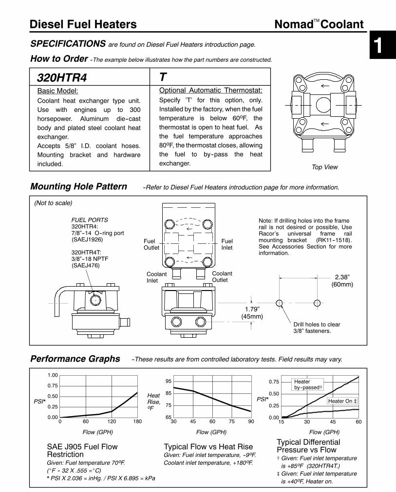
73
Diesel Fuel Heaters
320HTR4Basic Model:Coolant heat exchanger type unit.Use with engines up to 300horsepower. Aluminum die--castbody and plated steel coolant heatexchanger.Accepts 5/8” I.D. coolant hoses.Mounting bracket and hardwareincluded.
Mounting Hole Pattern
SPECIFICATIONS are found on Diesel Fuel Heaters introduction page.
Nomad Coolant
How to Order --The example below illustrates how the part numbers are constructed.
FUEL PORTS320HTR4:7/8”--14 O--ring port(SAEJ1926)
320HTR4T:3/8”--18 NPTF(SAEJ476)
(Not to scale)
--Refer to Diesel Fuel Heaters introduction page for more information.
TOptional Automatic Thermostat:Specify ’T’ for this option, only.Installed by the factory, when the fueltemperature is below 60oF, thethermostat is open to heat fuel. Asthe fuel temperature approaches80oF, the thermostat closes, allowingthe fuel to by--pass the heatexchanger.
Drill holes to clear3/8” fasteners.
Performance Graphs --These results are from controlled laboratory tests. Field results may vary.
Top View
2.38”(60mm)
CoolantInlet
CoolantOutlet
Note: If drilling holes into the framerail is not desired or possible, UseRacor’s universal frame railmounting bracket (RK11--1518).See Accessories Section for moreinformation.
1.79”(45mm)
TM
FuelOutlet
FuelInlet
0.00
0.25
0.50
0.75
15 30 45 60
PSI*
65
75
85
95
30 45 60 75 90
Flow (GPH)
HeatRise,oF
Typical Flow vs Heat RiseGiven: Fuel inlet temperature, --9oF.Coolant inlet temperature, +180oF.
0.00
0.25
0.50
0.75
1.00
0 60 120 180
Flow (GPH)
PSI*
SAE J905 Fuel FlowRestrictionGiven: Fuel temperature 70oF.(_F -- 32 X .555 =_C)* PSI X 2.036 = inHg. / PSI X 6.895 = kPa
Heaterby--passed[
Heater On }
Flow (GPH)
Typical DifferentialPressure vs Flow[ Given: Fuel inlet temperatureis +85oF (320HTR4T.)
} Given: Fuel inlet temperatureis +40oF, Heater on.
1

74
Diesel Fuel Heaters
HEATERBasic Thermoline designationThe unit uses ’oversize’ No.10 highquality fuel hose with an internalheating element. The heaterelement is a conductive polymericcore extruded between two parallelcopper bus wires and is infinitelytemperature self--regulating.In--cab underdash controller / relay(RK 14280--12 or --24) is included.
Product Notes
SPECIFICATIONS are found on Diesel Fuel Heaters introduction page.
Thermoline Heaters
How to Order --The example below illustrates how the part numbers are constructed.
INLET7/8”--14
45_ flare(SAEJ512)
(not to scale)
--Refer to Diesel Fuel Heaters introduction page for more information.
TO RELAY: EITHER WIRE MAY BEUSED FOR HOT OR GROUND.-- Both are Black 10 ga.wires,10 ft. long with 3/8” ring terminals.
0
5
10
15
0 100 200 300 400 500
Performance Graphs
Typical Heat Rise--All models.Given: Heat input (based on fueltemp.in the line) and Flow Rate (of thefuel based on engine speed & type).
Heat input (Watts)
Temp.Rise,oF
These results are from controlled laboratory tests. Field results may vary.
0100200300400500600
--50 0 50 100 150
Temperature oF
PowerinWatts
Typical Power Consumption(Power output decreases asfuel temperature rises)(_F -- 32 X .555 =_C)
500Specify Heater Power (in Watts)’150’ Recommended for cars or
trucks.
’300’ Recommended for engines100 to 200 horsepower.
’500’ Recommended for enginesover 200 horsepower.
24VSpecifyVoltage’12V’ for 12
volts.
’24V’ for 24volts.
OUTLET7/8”--1445_ flare(SAEJ512)
NOTE: THE INLET AND OUTLETFITTINGS ARE 45_ FLARE.Do not use with 37_ flare fittings.Use an adapter listed below:
#14201 --45_male by 1/4”NPT male(SAEJ476)
#14202 --45_male by 3/8”NPT male(SAEJ476)
#14203 --45_ male by 7/8”--14O--ring male(SAEJ514)
5/8” ( No.10 ) SAE100R2 Type A fuel hose
TM
0.0
0.5
1.0
1.5
2.0
0 60 120 180
Fuel Flow (GPH)
PSI*
Typical FuelFlow RestrictionGiven: Fuel temperature 70_F* PSI X 2.036 = inHg.PSI X 6.895 = kPa
150
300500
500300
15060 GPH
30 GPH
Length:See specification page

80
On and Off Highway Accessories Accessories
New Bowl Removal WrenchRacor now offers a hand wrench to remove all metal and see--thru spin--on bowls that feature external ribs. This includesthe following models: 025, 120, all 200 Series, 300 Series, 400 Series, 600 Series and Navistar metal bowls as used onthe 6.9 and 7.3 liter Ford Pickups.
By simply fitting the wrench over the bowl ribs, the bowl can be removed from the replaceable spin--on element with littleeffort. The wrench is made of a corrosion proof high--impact, high--strength engineered polymer.
Order Part Number 22628.
Specialty ProductsPart No. Description Qty.
RK31605 Parker Super O--lube, silicone base, 2 oz. tube 1ParkerSuperO--Lube
Racor coats the exterior ofmost aftermarket products in fourmajor colors:black, white, gold, and beige using a superior powder coating method.However, during the lifetime of the product minor dings and scratches willappear on the coating. Now, Racor offers our customers the availabilityof touch up paint for these occasions.
The touch--up colors are available in 1/2 fluid ounce ’bottles’ that includean applicator brush built right into the cap. The beige color is unique toRacor and is the only one that must be ordered through customer service.BEIGE is Racor part number RK10221.
The black, white, and gold colors are very good matches and are readilyavailable from the following sources: Auto Zone Stores,Checker/Kragen/Schucks Auto Stores, Grand Auto/Al’s Auto Stores,K--Mart, Napa Auto Stores, and Wal--Mart. These three colors arestandard Sherwin--WilliamsDupli--Color* automotive finish colors alreadyoffered to the general public. Source these colors at these locations, asthey will not be stocked by Racor.
Touch-up Paint
Part Numbers:BLACK is Dupli--Color* #SFGM1 (General Motors Black Clearcoat).WHITE is Dupli--Color* #SFGM153 (General Motors Classic White Clearcoat).GOLD is Dupli--Color* #SFGM491 (General Motors Gold Clearcoat).
These products have an approximate shelf life of two years if re--sealed correctly and are considered nonhazardous.They may be shipped via all modes without special precautions or paperwork.
*Dupli--Color is a registered trademark of Dupli--Color Products, The Specialty Division, Division of the Sherwin--Williams Co.
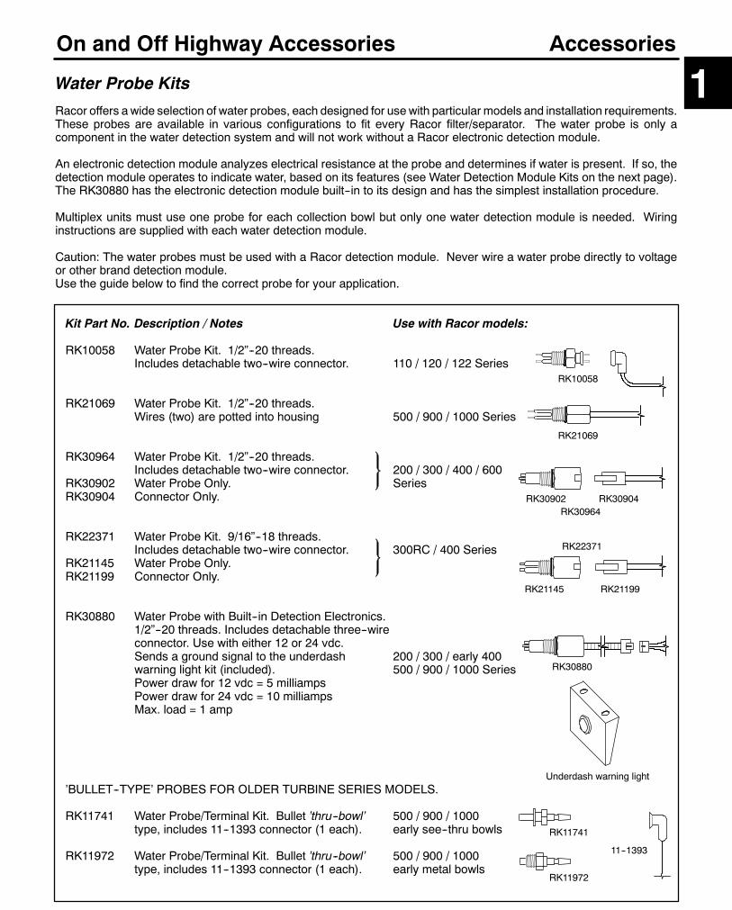
81
On and Off Highway Accessories
Kit Part No. Description / Notes Use with Racor models:
RK10058 Water Probe Kit. 1/2”--20 threads.Includes detachable two--wire connector. 110 / 120 / 122 Series
RK21069 Water Probe Kit. 1/2”--20 threads.Wires (two) are potted into housing 500 / 900 / 1000 Series
RK30964 Water Probe Kit. 1/2”--20 threads.Includes detachable two--wire connector. 200 / 300 / 400 / 600
RK30902 Water Probe Only. SeriesRK30904 Connector Only.
RK22371 Water Probe Kit. 9/16”--18 threads.Includes detachable two--wire connector. 300RC / 400 Series
RK21145 Water Probe Only.RK21199 Connector Only.
RK30880 Water Probe with Built--in Detection Electronics.1/2”--20 threads. Includes detachable three--wireconnector. Use with either 12 or 24 vdc.Sends a ground signal to the underdash 200 / 300 / early 400warning light kit (included). 500 / 900 / 1000 SeriesPower draw for 12 vdc = 5 milliampsPower draw for 24 vdc = 10 milliampsMax. load = 1 amp
’BULLET--TYPE’ PROBES FOR OLDER TURBINE SERIES MODELS.
RK11741 Water Probe/Terminal Kit. Bullet ’thru--bowl’ 500 / 900 / 1000type, includes 11--1393 connector (1 each). early see--thru bowls
RK11972 Water Probe/Terminal Kit. Bullet ’thru--bowl’ 500 / 900 / 1000type, includes 11--1393 connector (1 each). early metal bowls
RK21069
Accessories
RK11741
RK21145
RK11972
Water Probe Kits
RK21199
RK22371
1
11--1393
RK10058
RK30902 RK30904RK30964
RK30880
Racor offers a wide selection of water probes, each designed for use with particular models and installation requirements.These probes are available in various configurations to fit every Racor filter/separator. The water probe is only acomponent in the water detection system and will not work without a Racor electronic detection module.
An electronic detection module analyzes electrical resistance at the probe and determines if water is present. If so, thedetection module operates to indicate water, based on its features (see Water Detection Module Kits on the next page).The RK30880 has the electronic detection module built--in to its design and has the simplest installation procedure.
Multiplex units must use one probe for each collection bowl but only one water detection module is needed. Wiringinstructions are supplied with each water detection module.
Caution: The water probes must be used with a Racor detection module. Never wire a water probe directly to voltageor other brand detection module.Use the guide below to find the correct probe for your application.
Underdash warning light
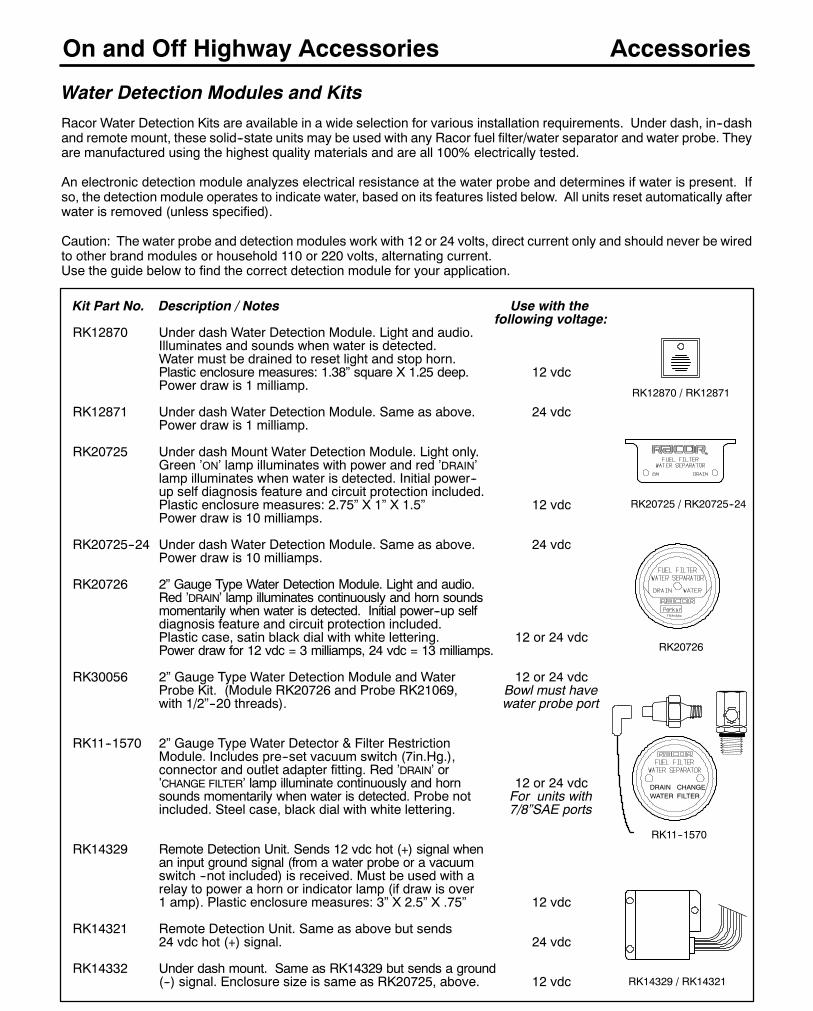
82
On and Off Highway Accessories
Kit Part No. Description / Notes Use with thefollowing voltage:
RK12870 Under dash Water Detection Module. Light and audio.Illuminates and sounds when water is detected.Water must be drained to reset light and stop horn.Plastic enclosure measures: 1.38” square X 1.25 deep. 12 vdcPower draw is 1 milliamp.
RK12871 Under dash Water Detection Module. Same as above. 24 vdcPower draw is 1 milliamp.
RK20725 Under dash Mount Water Detection Module. Light only.Green ’ON’ lamp illuminates with power and red ’DRAIN’lamp illuminates when water is detected. Initial power--up self diagnosis feature and circuit protection included.Plastic enclosure measures: 2.75” X 1” X 1.5” 12 vdcPower draw is 10 milliamps.
RK20725--24 Under dash Water Detection Module. Same as above. 24 vdcPower draw is 10 milliamps.
RK20726 2” Gauge Type Water Detection Module. Light and audio.Red ’DRAIN’ lamp illuminates continuously and horn soundsmomentarily when water is detected. Initial power--up selfdiagnosis feature and circuit protection included.Plastic case, satin black dial with white lettering. 12 or 24 vdcPower draw for 12 vdc = 3 milliamps, 24 vdc = 13 milliamps.
RK30056 2” Gauge Type Water Detection Module and Water 12 or 24 vdcProbe Kit. (Module RK20726 and Probe RK21069, Bowl must havewith 1/2”--20 threads). water probe port
RK11--1570 2” Gauge Type Water Detector & Filter RestrictionModule. Includes pre--set vacuum switch (7in.Hg.),connector and outlet adapter fitting. Red ’DRAIN’ or’CHANGE FILTER’ lamp illuminate continuously and horn 12 or 24 vdcsounds momentarily when water is detected. Probe not For units withincluded. Steel case, black dial with white lettering. 7/8”SAE ports
RK14329 Remote Detection Unit. Sends 12 vdc hot (+) signal whenan input ground signal (from a water probe or a vacuumswitch --not included) is received. Must be used with arelay to power a horn or indicator lamp (if draw is over1 amp). Plastic enclosure measures: 3” X 2.5” X .75” 12 vdc
RK14321 Remote Detection Unit. Same as above but sends24 vdc hot (+) signal. 24 vdc
RK14332 Under dash mount. Same as RK14329 but sends a ground(--) signal. Enclosure size is same as RK20725, above. 12 vdc
Accessories
Water Detection Modules and Kits
Racor Water Detection Kits are available in a wide selection for various installation requirements. Under dash, in--dashand remote mount, these solid--state units may be used with any Racor fuel filter/water separator and water probe. Theyare manufactured using the highest quality materials and are all 100% electrically tested.
An electronic detection module analyzes electrical resistance at the water probe and determines if water is present. Ifso, the detection module operates to indicate water, based on its features listed below. All units reset automatically afterwater is removed (unless specified).
Caution: The water probe and detection modules work with 12 or 24 volts, direct current only and should never be wiredto other brand modules or household 110 or 220 volts, alternating current.Use the guide below to find the correct detection module for your application.
RK20725 / RK20725--24
RK20726
RK12870 / RK12871
RK11--1570
DRAINWATER
CHANGEFILTER
RK14329 / RK14321
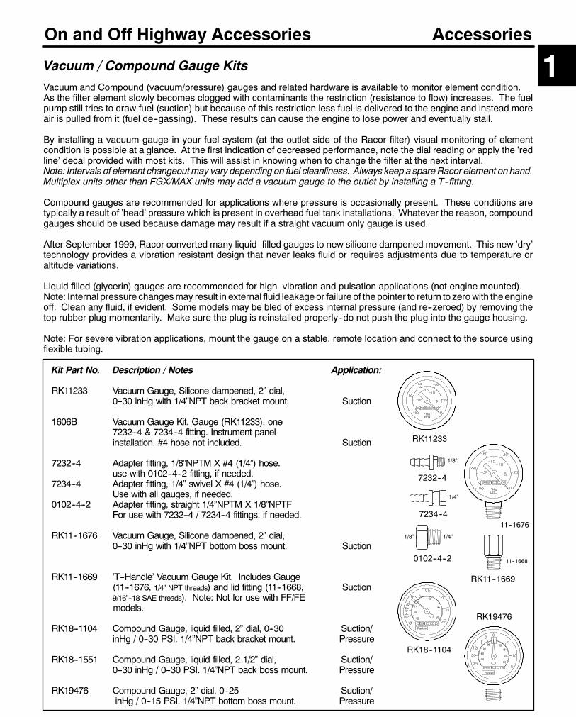
83
On and Off Highway Accessories
Kit Part No. Description / Notes Application:
RK11233 Vacuum Gauge, Silicone dampened, 2” dial,0--30 inHg with 1/4”NPT back bracket mount. Suction
1606B Vacuum Gauge Kit. Gauge (RK11233), one7232--4 & 7234--4 fitting. Instrument panelinstallation. #4 hose not included. Suction
7232--4 Adapter fitting, 1/8”NPTM X #4 (1/4”) hose.use with 0102--4--2 fitting, if needed.
7234--4 Adapter fitting, 1/4” swivel X #4 (1/4”) hose.Use with all gauges, if needed.
0102--4--2 Adapter fitting, straight 1/4”NPTM X 1/8”NPTFFor use with 7232--4 / 7234--4 fittings, if needed.
RK11--1676 Vacuum Gauge, Silicone dampened, 2” dial,0--30 inHg with 1/4”NPT bottom boss mount. Suction
RK11--1669 ’T--Handle’ Vacuum Gauge Kit. Includes Gauge(11--1676, 1/4” NPT threads) and lid fitting (11--1668, Suction9/16”--18 SAE threads). Note: Not for use with FF/FEmodels.
RK18--1104 Compound Gauge, liquid filled, 2” dial, 0--30 Suction/inHg / 0--30 PSI. 1/4”NPT back bracket mount. Pressure
RK18--1551 Compound Gauge, liquid filled, 2 1/2” dial, Suction/0--30 inHg / 0--30 PSI. 1/4”NPT back boss mount. Pressure
RK19476 Compound Gauge, 2” dial, 0--25 Suction/inHg / 0--15 PSI. 1/4”NPT bottom boss mount. Pressure
Accessories
Vacuum / Compound Gauge Kits 1Vacuum and Compound (vacuum/pressure) gauges and related hardware is available to monitor element condition.As the filter element slowly becomes clogged with contaminants the restriction (resistance to flow) increases. The fuelpump still tries to draw fuel (suction) but because of this restriction less fuel is delivered to the engine and instead moreair is pulled from it (fuel de--gassing). These results can cause the engine to lose power and eventually stall.
By installing a vacuum gauge in your fuel system (at the outlet side of the Racor filter) visual monitoring of elementcondition is possible at a glance. At the first indication of decreased performance, note the dial reading or apply the ’redline’ decal provided with most kits. This will assist in knowing when to change the filter at the next interval.Note: Intervals of element changeoutmay vary depending on fuel cleanliness. Always keep a spareRacor element on hand.Multiplex units other than FGX/MAX units may add a vacuum gauge to the outlet by installing a T--fitting.
Compound gauges are recommended for applications where pressure is occasionally present. These conditions aretypically a result of ’head’ pressure which is present in overhead fuel tank installations. Whatever the reason, compoundgauges should be used because damage may result if a straight vacuum only gauge is used.
After September 1999, Racor converted many liquid--filled gauges to new silicone dampened movement. This new ’dry’technology provides a vibration resistant design that never leaks fluid or requires adjustments due to temperature oraltitude variations.
Liquid filled (glycerin) gauges are recommended for high--vibration and pulsation applications (not engine mounted).Note: Internal pressure changesmay result in external fluid leakage or failure of the pointer to return to zerowith theengineoff. Clean any fluid, if evident. Some models may be bled of excess internal pressure (and re--zeroed) by removing thetop rubber plug momentarily. Make sure the plug is reinstalled properly--do not push the plug into the gauge housing.
Note: For severe vibration applications, mount the gauge on a stable, remote location and connect to the source usingflexible tubing.
RK19476
RK18--1104
RK11233
7232--4
7234--4
0102--4--2
11--1676
11--1668
RK11--1669
1/8”
1/4”
1/8” 1/4”

84
On and Off Highway Accessories Accessories
Vacuum Gauge or Switch Adapter Fittings
Fitting Part No. Old Part No. Use with: Thread 1 Fitting end 2 Qty.
913--O6--D6 9010HF6--6DTB 500 Series 9/16”--18 3/8” hose 10Features 1/8”NPTF to attach vacuum gauge hose fitting.
911--O8--D8 New 500/4120R 3/4”--16 3/4”--16 SAE 10911--O10--D10 New 900/1000 7/8”--14 7/8”--14 SAE 109040--10--8DT No change 900/1000 7/8”--14 1/2”--14 NPTF 10
Both above feature 1/4”NPTF to attach vacuum gauge or hose fitting.F2
’913’
F2
T1
T1
1/8”NPTF
1/4”NPTF
’9040 / 911’
Parker AdapterFittings
Parker TeeFitting
1/4”NPTF
FOR RACOR UNITS WITH TAPERED THREAD (NPTF) PORTS. SOURCE FITTINGS FROM THE PARKERHANNIFIN DIVISION NOTED BELOW. CALL 1--800--C--PARKER FOR THE NEAREST DEALER.Tee Fitting Description Hose Products Division Tube Fittings DivisionPort sizes all 3/8”NPTF #012T--6--6 #3/8MROPort sizes all 3/4”NPT #012T--8--8 #1/2MROAdapter Fitting Hose Products Division Tube Fittings Division3/8”NPTF X 1/4”NPTF #0102--6--4 #3/8X1/4PTR3/4”NPTF X 1/4”NPTF #0102--12--4 #3/4X1/4PTR
Top viewshowingcenterthreads.
Kit Part No. Description / Notes
10202 FORD Spin--On Cap Assembly (not a filter). Threads: 16 X 1.5mm,3.43” diameter, 4.4” long. Gasket outside diameter: 2.95” X .30 thick.
11548 CUMMINS Spin--On Cap Assembly (not a filter). Threads: 1”--14,3.63” diameter, 3.5” long. Gasket outside diameter: 2.83” X .22” thick.
22021 FORD Spin--On Cap Assembly (not a filter). Threads: 1”--14,3.63” diameter, 3.5” long. Gasket outside diameter: 3.60” X .25” thick.
Engine Spin-On Filter ’Block-off’ Caps
Mounting Bracket Kits
Kit Part No. Description / Notes Use with:
15205 Automobile & Light Truck Mounting Kit. Features flexibleplated 14 gauge steel arms that can be cut and formed 110 /120 /200to fit many surfaces. Includes mounting hardware. 400 / 500 / 600
RK11--1518 Frame Rail Mounting Bracket Kit. Features anadjustable powder coated 10 gauge steel design to fitframe rails up to 10” in height, 3 3/4” wide and 13/16” 900 / 1000thick. Includes mounting hardware. 6400 / Nomad Vehicle
Frame Rail
15205
RK11--1518
RK20163
RK21030
Vacuum Switch / Connector Kits
Kit Part No. Description / Notes
RK20163 Vacuum Switch Kit. 12 or 24 vdc, non--adjustable, ’NORMALLY OPEN’contacts close at 7 inHg, 1/8”NPT threads. For use with all models.
RK21030 Vacuum Switch Connector Kit (for use with above). Molded connectorwith single 18 AWG., 18” blue wire lead.
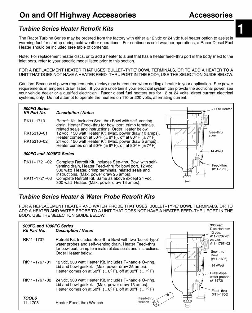
85
On and Off Highway Accessories
500FG SeriesKit Part No. Description / Notes
RK11--1710 Retrofit Kit. Includes See--thru Bowl with self--ventingdrain, Heater Feed--thru for bowl port, crimp terminals,related seals and instructions. Order Heater below.
RK15310--01 12 vdc, 150 watt Heater Kit. (Max. power draw 10 amps).Heater comes on at 50oF (±8o F), off at 80o F (±7o F)
RK15310--02 24 vdc, 150 watt Heater Kit. (Max. power draw 5 amps).Heater comes on at 50oF (±8o F), off at 80o F (±7o F)
900FG and 1000FG Series
RK11--1721--02 Complete Retrofit Kit. Includes See--thru Bowl with self--venting drain, Heater Feed--thru for bowl port, 12 vdc,300 watt Heater, crimp terminals, related seals andinstructions. (Max. power draw 25 amps).
RK11--1721--03 Complete Retrofit Kit. Same as above except 24 vdc,300 watt Heater. (Max. power draw 13 amps).
Accessories
Turbine Series Heater Retrofit Kits 1The Racor Turbine Series may be ordered from the factory with either a 12 vdc or 24 vdc fuel heater option to assist inwarming fuel for startup during cold weather operations. For continuous cold weather operations, a Racor Diesel FuelHeater should be included (see table of contents).
Note: For replacement heater discs, or to add a heater to a unit that has a heater feed--thru port in the body (next to theinlet port), refer to your specific model listed prior to this section.
FOR A REPLACEMENT HEATER THAT USES ’BULLET--TYPE’ BOWL TERMINALS, OR TO ADD A HEATER TO AUNIT THAT DOES NOT HAVE A HEATER FEED--THRU PORT IN THE BODY, USE THE SELECTION GUIDE BELOW.
Caution: Because of power requirements, a relay may be required when adding a heater to your application. See powerrequirements in amperes draw, listed. If you are uncertain if your electrical system can provide the additional power, seeyour vehicle dealer or a qualified electrician. Racor diesel fuel heaters are for 12 or 24 volts, direct current electricalsystems, only. Do not attempt to operate the heaters on 110 or 220 volts, alternating current.
300 wattDisc Heaters:12 vdc.#11--1767--0124 vdc.#11--1767--02
Feed--thru(#11--1700)
See--thruBowl(#11--1606)
Bullet--typewater probes(#11972)
900FG and 1000FG SeriesKit Part No. Description / Notes
RK11--1737 Retrofit Kit. Includes See--thru Bowl with two ’bullet--type’water probes and self--venting drain, Heater Feed--thrufor bowl port, crimp terminals related seals and instructions.Order Heater below.
RK11--1767--01 12 vdc, 300 watt Heater Kit. Includes T--handle O--ring,Lid and bowl gasket. (Max. power draw 25 amps).Heater comes on at 50oF (±8o F), off at 80oF (±7o F)
RK11--1767--02 24 vdc, 300 watt Heater Kit. Includes T--handle O--ring,Lid and bowl gasket. (Max. power draw 13 amps).Heater comes on at 50oF (±8o F), off at 80oF (±7o F)
TOOLS11--1708 Heater Feed--thru Wrench
Disc Heater
Feed--thru(#11--1700)
See--thruBowl
Turbine Series Heater & Water Probe Retrofit Kits
FOR A REPLACEMENT HEATER AND WATER PROBE THAT USES ’BULLET--TYPE’ BOWL TERMINALS, OR TOADD A HEATER AND WATER PROBE TO A UNIT THAT DOES NOT HAVE A HEATER FEED--THRU PORT IN THEBODY, USE THE SELECTION GUIDE BELOW.
Feed--thruwrench
14 AWG
14 AWG

86
On and Off Highway Accessories Accessories
Kit Part No. Description / Notes
500FG Series --May only be used with 500 S/S unit featuring 9/16”-18 ports.
75500FGX Kit Duplex Conversion Kit. Valve fuel ports: 3/4”SAE O--ring boss (SAEJ1926)
900FG and 1000FG Series --May only be used with units featuring 7/8”--14 ports.
73 Kit Duplex Conversion Kit. Manifold tube inlet and outlet: 3/4”NPT (SAEJ476)900 or 1000 Series
75 Kit Duplex Conversion Kit (with Four Ball Valves). Manifold tube inlet andoutlet: 3/4”NPT (SAEJ476). 1000 only.
75FGX Kit Duplex Conversion Kit (with Selector Valve). Valve inlet and outlet:7/8”SAE 37_ male (SAEJ514). 1000 only.
77 Kit Triplex Conversion Kit. Manifold pipe inlet and outlet: 1”NPT (SAEJ476).1000 only.
79 Kit Triplex Conversion Kit (with Six Ball Valves). Manifold Inlet and outlet:1”NPT (SAEJ476). 1000 only.
73 Kit
75 Kit77 Kit 79 Kit75FGX Kit
75500FGX Kit
Kit Part No. Description / Notes
RK11861 Heater Relay Kit for 12 vdc. Remote mount. Handles up to 300 wattsor 25 amps. Includes fuse and holder.
RK11862 Heater Relay Kit for 24 vdc. Remote mount. Handles up to 360 wattsor 15 amps. Includes fuse and holder
RK19490--12 Heavy--Duty Relay Kit for 12 vdc. Under dash mount. Handles up to600 watts or 50 amps.
RK19490--24 Heavy--Duty Relay Kit for 24 vdc. Under dash mount. Handles up to900 watts or 37 amps.
Heater Electrical Relay Kits
The following relay kits may be necessary when installing Racor Heater Kits due to the power demand. Standard OE fuses,wiring and alternators may be unable to carry the load without overheating or potential shorting, creating a serious condition.
Caution: If you are uncertain if your electrical system can provide the additional power draw, consult your equipmentdealer or a qualified electrician.
RESET
DIESEL FUEL HEATERCONTROL
ON/OFF
RK19490--12 / 24
RK11861 / 62
Multiplex Filter/Separator Conversion Kits - Filter/Separators not included.
Racor conversion kits may be used to build a ’manifolded’ unit in order to increase fuel flow or contaminant holdingcapacity. Valved models allow servicing of the fuel filter/water separator, even while the engine is running. Conversionkits are economical alternatives that permit the use of an existing unit. Additional units to complete the system may bepurchased from your dealer as they are not included with these kits.Note: Racor conversion kits are not intended for commercial marine use. See Section 2 for USCG accepted products.
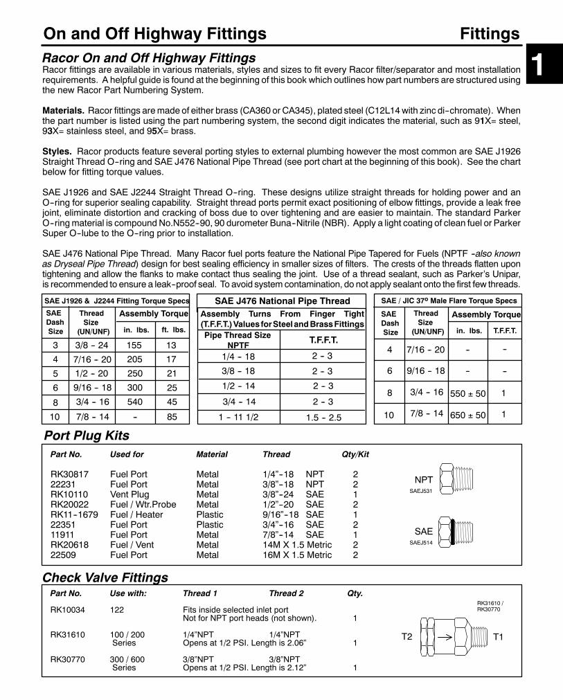
87
On and Off Highway Fittings
Port Plug Kits
Fittings
1
Part No. Used for Material Thread Qty/Kit
RK30817 Fuel Port Metal 1/4”--18 NPT 222231 Fuel Port Metal 3/8”--18 NPT 2RK10110 Vent Plug Metal 3/8”--24 SAE 1RK20022 Fuel / Wtr.Probe Metal 1/2”--20 SAE 2RK11--1679 Fuel / Heater Plastic 9/16”--18 SAE 122351 Fuel Port Plastic 3/4”--16 SAE 211911 Fuel Port Metal 7/8”--14 SAE 1RK20618 Fuel / Vent Metal 14M X 1.5 Metric 222509 Fuel Port Metal 16M X 1.5 Metric 2
NPT
SAE
SAEJ531
SAEJ514
Check Valve Fittings
T1T2
RK31610 /RK30770
Part No. Use with: Thread 1 Thread 2 Qty.
RK10034 122 Fits inside selected inlet portNot for NPT port heads (not shown). 1
RK31610 100 / 200 1/4”NPT 1/4”NPTSeries Opens at 1/2 PSI. Length is 2.06” 1
RK30770 300 / 600 3/8”NPT 3/8”NPTSeries Opens at 1/2 PSI. Length is 2.12” 1
Racor On and Off Highway FittingsRacor fittings are available in various materials, styles and sizes to fit every Racor filter/separator and most installationrequirements. A helpful guide is found at the beginning of this book which outlines how part numbers are structured usingthe new Racor Part Numbering System.
Materials. Racor fittings aremade of either brass (CA360 or CA345), plated steel (C12L14with zinc di--chromate). Whenthe part number is listed using the part numbering system, the second digit indicates the material, such as 91X= steel,93X= stainless steel, and 95X= brass.
Styles. Racor products feature several porting styles to external plumbing however the most common are SAE J1926Straight Thread O--ring and SAE J476 National Pipe Thread (see port chart at the beginning of this book). See the chartbelow for fitting torque values.
SAE J1926 and SAE J2244 Straight Thread O--ring. These designs utilize straight threads for holding power and anO--ring for superior sealing capability. Straight thread ports permit exact positioning of elbow fittings, provide a leak freejoint, eliminate distortion and cracking of boss due to over tightening and are easier to maintain. The standard ParkerO--ringmaterial is compoundNo.N552--90, 90 durometer Buna--Nitrile (NBR). Apply a light coating of clean fuel or ParkerSuper O--lube to the O--ring prior to installation.
SAE J476 National Pipe Thread. Many Racor fuel ports feature the National Pipe Tapered for Fuels (NPTF --also knownas Dryseal Pipe Thread) design for best sealing efficiency in smaller sizes of filters. The crests of the threads flatten upontightening and allow the flanks to make contact thus sealing the joint. Use of a thread sealant, such as Parker’s Unipar,is recommended to ensure a leak--proof seal. To avoid system contamination, do not apply sealant onto the first few threads.
SAE J1926 & J2244 Fitting Torque Specs
SAEDashSize
ThreadSize
(UN/UNF)
Assembly Torque
in. lbs. ft. lbs.
3 3/8 -- 24 155 13
4
5
6
8
10
7/16 -- 20
1/2 -- 20
9/16 -- 18
3/4 -- 16
7/8 -- 14
205
250
300
540
--
17
21
25
45
85
Assembly Turns From Finger Tight(T.F.F.T.)Values forSteelandBrassFittingsPipe Thread Size
NPTFT.F.F.T.
1/4 -- 18
3/8 -- 18
1/2 -- 14
3/4 -- 14
2 -- 3
1.5 -- 2.51 -- 11 1/2
2 -- 3
2 -- 3
2 -- 3
Assembly Torque
in. lbs. T.F.F.T.
4
6
8
10
7/16 -- 20
9/16 -- 18
3/4 -- 16
7/8 -- 14
-- --
-- --
1
1
550 � 50
650 � 50
SAE / JIC 37o Male Flare Torque Specs
SAEDashSize
ThreadSize
(UN/UNF)
SAE J476 National Pipe Thread

88
On and Off Highway Fittings100, 200, 300, 400 & 600 Series Fittings --Package quantity is 10 pcs.
Fittings
Part No. Old Part No. Thread 1 Hose 2 Tube or Hose(SAEJ476) (or thread) Size Number
953--N4--H5 No change 1/4”--18 5/16” 5913--N4--H6 953--N4--H6 1/4”--18 3/8” 6913--N6--H6 953--N6--H6 3/8”--18 3/8” 6
951--N4--H4 RK30815 1/4”--18 1/4” 4951--N4--H5 RK21132 1/4”--18 5/16” 5911--N4--H6 951--N4--H6 1/4”--18 3/8” 6951--N6--H4 New 3/8”--18 1/4” 4951--N6--H5 No change 3/8”--18 5/16” 5911--N6--H6 951--N6--H6 3/8”--18 3/8” 6911--N6--H8 951--N6--H8 3/8”--18 1/2” 8
951--N6--J6 0103--6--6B 3/8”--18 9/16”--18UNF 6951--N6--J8 0103--6--8B 3/8”--18 3/4”--16UNF 8
955--W6--H6 30682--6--6B 9/16”--18UNF 3/8” 6955--W8--H8 30682--8--8B 3/4”--16UNF 1/2” 8
T1T2
T1
T2
T2 T1
T1
500FG (MAX) Series Fittings --Package quantity is 10 pcs.
Fitting Part No. Old Part No. Thread 1 Thread 2 Tube or Hose(SAEJ1926) (or Hose I.D.) Size Number
9010--6--4 No change 9/16”--18 7/16”--20 49010--6--6 No change 9/16”--18 9/16”--18 6913--O8--J6 New 3/4”--16 9/16”--18 6913--O8--J8 9010--8--8 3/4”--16 3/4”--16 8913--O8--J10 9010--8--10 3/4”--16 7/8”--14 10
9020--6--4 No change 9/16”--18 7/16”--20 49020--6--6 No change 9/16”--18 9/16”--18 6911--O8--J6 New 3/4”--16 9/16”--18 6911--O8--J8 9020--8--8 3/4”--16 3/4”--16 8911--O8--J10 9020--8--10 3/4”--16 7/8”--14 10
911--O4--F4 9040--4--4 7/16”--20 1/4”--18 49040--6--4 No change 9/16”--18 1/4”--18 49040--6--6 No change 9/16”--18 3/8”--18 6911--O8--F4 New 3/4”--16 1/4”--18 4911--O8--F6 New 3/4”--16 3/8”--18 6911--O8--F8 9040--8--8 3/4”--16 1/2”--14 8
913--O6--H5 9010HF--6--5/6 9/16”--18 5/16” 5913--O6--H6 9010HF--6--5/6 9/16”--18 3/8” 6913--O8--H5 New 3/4”--16 5/16 5913--O8--H6 New 3/4”--16 3/8” 6913--O8--H82 New 3/4”--16 1/2” 8913--O8--H102 New 3/4”--16 5/8” 10
911--O6--H5/6 9020HF--6--5/6 9/16”--18 5/16--3/8” 5 -- 6911--O8--H62 New 3/4”--16 3/8” 6911--O8--H82 New 3/4”--16 1/2” 8911--O8--H102 New 3/4”--16 5/8” 10
T2
T1
T1
T2
SAE R4Hose I. D.1
T1
T1
T1
T2
’9010 & 913’ SAEElbow
’9020 & 911’ SAEStraight
’9040 & 911’ NPTFemale
’913’ Barbed Elbow
’911’ Barbed Straight
’913’ NPT BeadedElbow
’911’ NPT BarbedStraight
’951’ SAE Adapter
’955’ SAE Swivel
1 Illustration may not represent fitting contour exactly. Parker 800 Series (SAE R4) Push--Lok lowpressure hose recommended. Source from Parker Hannifin Corporation, Hose Products Division.For your local distributor call: (216) 943--5700, E.S.T. 2 Hose bead fitting, requires hose clamp.
91X fittings are made of steel, and 95X fittings are made of brass. Plated steel fittings are recommended for applications exposed to salt spray.
37o

89
On and Off Highway Fittings
Fitting Part No. Adapter Description Thread 1 Thread 2
911--W10--N6 Straight Swivel, SAE X NPTM 7/8”--14 3/8”--18911--W10--N8 Straight Swivel, SAE X NPTM 7/8”--14 1/2”--14911--W10--N12 Straight Swivel, SAE X NPTM 7/8”--14 3/4”--14911--W10--B8 Straight Swivel, SAE X BSPT 7/8”--14 1/2”--14
913--W10--N8 Elbow Swivel, SAE X NPTM 7/8”--14 1/2”--14
911--W10--F8 Straight Swivel, SAE X NPTF 7/8”--14 1/2”--14911--W10--F12 Straight Swivel, SAE X NPTF 7/8”--14 3/4”--14
913--W10--F8 Elbow Swivel, SAE X NPTF 7/8”--14 1/2”--14
Fitting Part No. Adapter Description Thread 1 Hose I.D.(SAE R5)
915--W10--R8 Straight Swivel, SAE X Hose 7/8”--14 13/32” (#8)915--W10--R10 Straight Swivel, SAE X Hose 7/8”--14 1/2” (#10)915--W10--R12 Straight Swivel, SAE X Hose 7/8”--14 5/8” (#12)
917--W10--R8 Elbow Swivel, SAE X Hose 7/8”--14 13/32” (#8)917--W10--R10 Elbow Swivel, SAE X Hose 7/8”--14 1/2” (#10)917--W10--R12 Elbow Swivel, SAE X Hose 7/8”--14 5/8” (#12)
(SAE R4)955--W10--H8 Straight Swivel, SAE X Hose 7/8”--14 1/2” (#8)955--W10--H10 Straight Swivel, SAE X Hose 7/8”--14 5/8” (#10)917--W10--H10 Elbow Swivel, SAE X Hose 7/8”--14 5/8” (#10)
Fittings
T2
75/900FGX (MAX) & 75/1000FGX (MAX) Series Fittings --Package quantity is 1 each.
T2
T2
T2
1
’911’ Straight
’911’ Straight
’913’ Elbow
’913’ Elbow
’915’ Straight
’955’ Straight
’917’ Elbow (R5)
’917’ Elbow (R4)
Hose
Hose
900FG (MAX) & 1000FG (MAX) Series Fittings --Package quantity is 10 pcs.
SAE Elbow Fitting Old Part No. Thread 1 Thread 2 Tube or HosePart No. (SAEJ1926) (or Hose I.D.) Size Number
9010--10--8 No change 7/8”--14 3/4”--16 89010--10--10 No change 7/8”--14 7/8”--14 10
SAE Strt. Fitting9020--10--6 No change 7/8”--14 9/16”--18 69020--10--8 No change 7/8”--14 3/4”--16 89020--10--10 No change 7/8”--14 7/8”--14 10
SAE to NPTF911--O10--F4 9040--10--4 7/8”--14 1/4”--18 4911--O10--F6 9040--10--6 7/8”--14 3/8”--18 6911--O10--F8 9040--10--8 7/8”--14 1/2”--14 8911--O10--F12 9040--10--12 7/8”--14 3/4”--14 12
SAE to Hose913--O10--H5 9010HF--10--6 7/8”--14 5/16” 5913--O10--H6 9010HF--10--8 7/8”--14 3/8” 6913--O10--H8 9010HF--10--10 7/8”--14 1/2” 8913--O10--H10 9010HF--10--12 7/8”--14 5/8 ” 10913--O10--H12 New 7/8”--14 3/4” 12
SAE to Hose911--O10--H5 9020HF--10--6 7/8”--14 5/16” 5911--O10--H6 9020HF--10--8 7/8”--14 3/8” 6911--O10--H8 9020HF--10--10 7/8”--14 1/2” 8911--O10--H10 9020HF--10--12 7/8”--14 5/8” 10911--O10--H12 New 7/8”--14 3/4” 12
T2
T1
T1
T2
SAE R4Hose I. D.1
T1
T1
T1
T2
’9010 & 913’ SAEElbow
’9020 & 911’ SAEStraight
’9040 & 911’ NPTFemale
’913’ Barbed Elbow
’911’ Barbed Straight
1 Illustrationmay not represent fitting contour exactly. Parker 800Series (SAER4) Push--Lok lowpressure hose recommended. Source from Parker Hannifin Corporation, Hose ProductsDivision. For your local distributor call: (216) 943--5700, E.S.T.
Racor Products Section 2 Marine Products
Global FiltrationTechnology
Help & General Information
?
Selection
Gasoline Series
025 & 32013 32020
120/320/660/3120
Diesel Spin On
110A
120RMAM
200 Series
400 Series
Turbine Series
500MA
900MA
1000MA
73/1000MA
75/500MAX
75/900MAX
75/1000MAX
77/1000MA
79/1000MAV
Fuel/Air Seperators
Drinking Water Filters
Air Filtration
Accessories
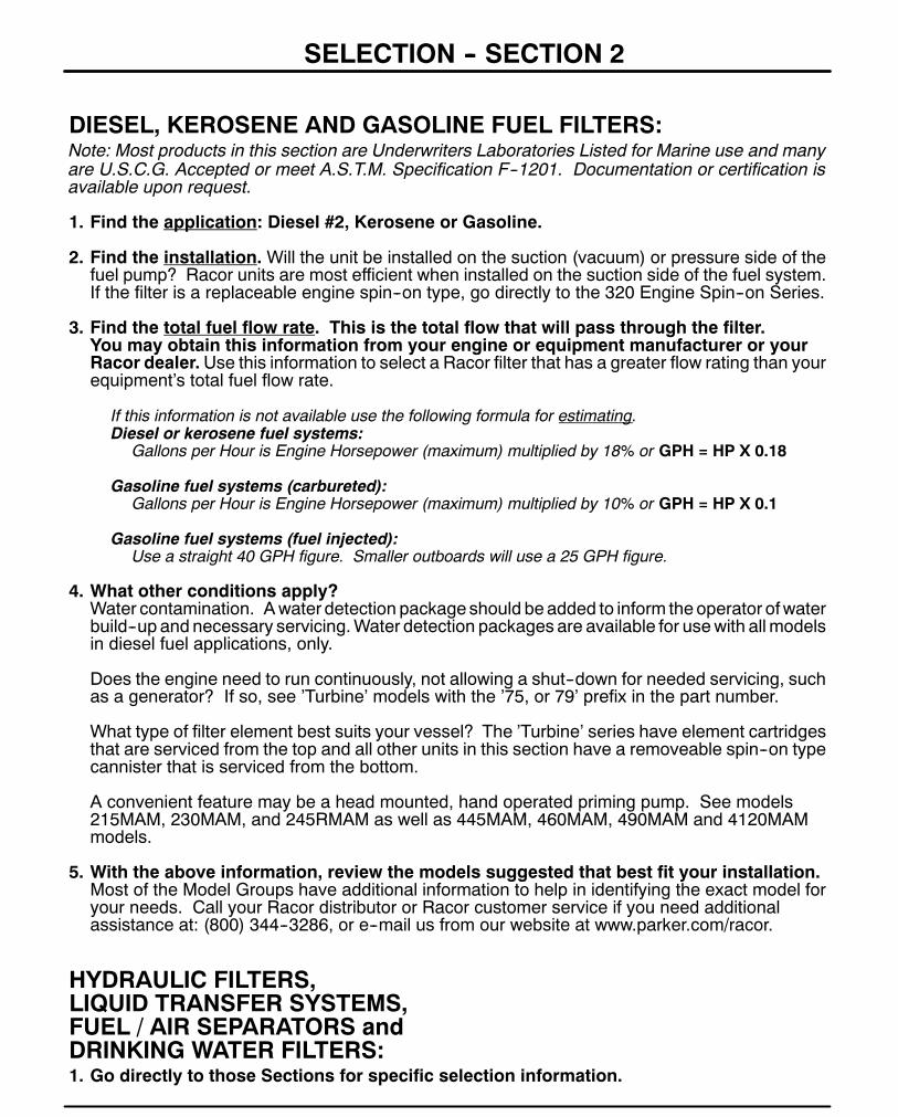
92
SELECTION -- SECTION 2
DIESEL, KEROSENE AND GASOLINE FUEL FILTERS:Note: Most products in this section are Underwriters Laboratories Listed for Marine use and manyare U.S.C.G. Accepted or meet A.S.T.M. Specification F--1201. Documentation or certification isavailable upon request.
1. Find the application: Diesel #2, Kerosene or Gasoline.
2. Find the installation.Will the unit be installed on the suction (vacuum) or pressure side of thefuel pump? Racor units are most efficient when installed on the suction side of the fuel system.If the filter is a replaceable engine spin--on type, go directly to the 320 Engine Spin--on Series.
3. Find the total fuel flow rate. This is the total flow that will pass through the filter.You may obtain this information from your engine or equipment manufacturer or yourRacor dealer.Use this information to select a Racor filter that has a greater flow rating than yourequipment’s total fuel flow rate.
If this information is not available use the following formula for estimating.Diesel or kerosene fuel systems:
Gallons per Hour is Engine Horsepower (maximum) multiplied by 18% or GPH = HP X 0.18
Gasoline fuel systems (carbureted):Gallons per Hour is Engine Horsepower (maximum) multiplied by 10% or GPH = HP X 0.1
Gasoline fuel systems (fuel injected):Use a straight 40 GPH figure. Smaller outboards will use a 25 GPH figure.
4. What other conditions apply?Water contamination. Awater detection package should be added to inform the operator ofwaterbuild--up and necessary servicing.Water detection packages are available for usewith allmodelsin diesel fuel applications, only.
Does the engine need to run continuously, not allowing a shut--down for needed servicing, suchas a generator? If so, see ’Turbine’ models with the ’75, or 79’ prefix in the part number.
What type of filter element best suits your vessel? The ’Turbine’ series have element cartridgesthat are serviced from the top and all other units in this section have a removeable spin--on typecannister that is serviced from the bottom.
A convenient feature may be a head mounted, hand operated priming pump. See models215MAM, 230MAM, and 245RMAM as well as 445MAM, 460MAM, 490MAM and 4120MAMmodels.
5. With the above information, review the models suggested that best fit your installation.Most of the Model Groups have additional information to help in identifying the exact model foryour needs. Call your Racor distributor or Racor customer service if you need additionalassistance at: (800) 344--3286, or e--mail us from our website at www.parker.com/racor.
HYDRAULIC FILTERS,LIQUID TRANSFER SYSTEMS,FUEL / AIR SEPARATORS andDRINKING WATER FILTERS:1. Go directly to those Sections for specific selection information.
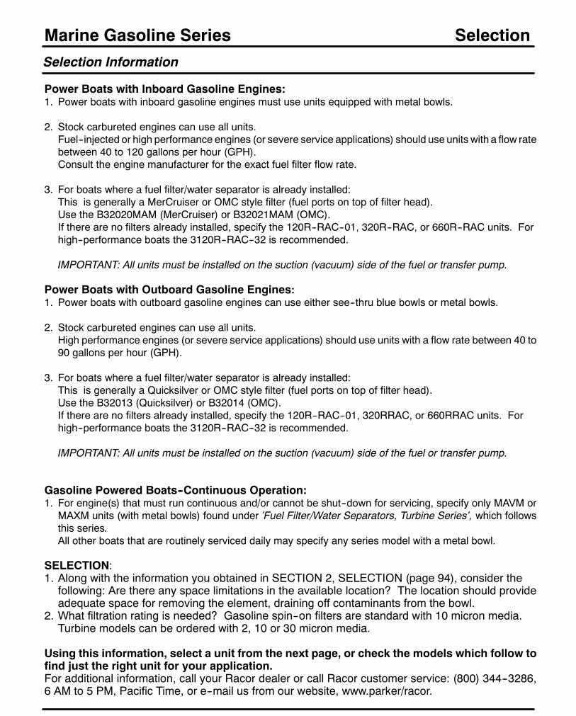
94
Marine Gasoline SeriesSelection Information
Power Boats with Inboard Gasoline Engines:1. Power boats with inboard gasoline engines must use units equipped with metal bowls.
2. Stock carbureted engines can use all units.Fuel--injected or high performance engines (or severe service applications) should use units with a flow ratebetween 40 to 120 gallons per hour (GPH).Consult the engine manufacturer for the exact fuel filter flow rate.
3. For boats where a fuel filter/water separator is already installed:This is generally a MerCruiser or OMC style filter (fuel ports on top of filter head).Use the B32020MAM (MerCruiser) or B32021MAM (OMC).If there are no filters already installed, specify the 120R--RAC--01, 320R--RAC, or 660R--RAC units. Forhigh--performance boats the 3120R--RAC--32 is recommended.
IMPORTANT: All units must be installed on the suction (vacuum) side of the fuel or transfer pump.
Power Boats with Outboard Gasoline Engines:1. Power boats with outboard gasoline engines can use either see--thru blue bowls or metal bowls.
2. Stock carbureted engines can use all units.High performance engines (or severe service applications) should use units with a flow rate between 40 to90 gallons per hour (GPH).
3. For boats where a fuel filter/water separator is already installed:This is generally a Quicksilver or OMC style filter (fuel ports on top of filter head).Use the B32013 (Quicksilver) or B32014 (OMC).If there are no filters already installed, specify the 120R--RAC--01, 320RRAC, or 660RRAC units. Forhigh--performance boats the 3120R--RAC--32 is recommended.
IMPORTANT: All units must be installed on the suction (vacuum) side of the fuel or transfer pump.
Gasoline Powered Boats--Continuous Operation:1. For engine(s) that must run continuous and/or cannot be shut--down for servicing, specify only MAVM or
MAXM units (with metal bowls) found under ’Fuel Filter/Water Separators, Turbine Series’, which followsthis series.All other boats that are routinely serviced daily may specify any series model with a metal bowl.
SELECTION:1. Along with the information you obtained in SECTION 2, SELECTION (page 94), consider thefollowing: Are there any space limitations in the available location? The location should provideadequate space for removing the element, draining off contaminants from the bowl.
2. What filtration rating is needed? Gasoline spin--on filters are standard with 10 micron media.Turbine models can be ordered with 2, 10 or 30 micron media.
Using this information, select a unit from the next page, or check the models which follow tofind just the right unit for your application.For additional information, call your Racor dealer or call Racor customer service: (800) 344--3286,6 AM to 5 PM, Pacific Time, or e--mail us from our website, www.parker/racor.
Selection
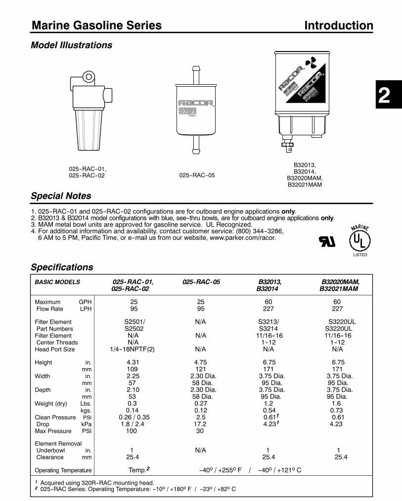
95
Marine Gasoline Series
SpecificationsBASIC MODELS 025-RAC-01, 025-RAC-05 B32013, B32020MAM,
025-RAC-02 B32014 B32021MAM
Maximum GPH 25 25 60 60Flow Rate LPH 95 95 227 227
Filter Element S2501/ N/A S3213/ S3220ULPart Numbers S2502 S3214 S3220ULFilter Element N/A N/A 11/16--16 11/16--16Center Threads N/A 1--12 1--12Head Port Size 1/4--18NPTF(2) N/A N/A N/A
Height in. 4.31 4.75 6.75 6.75mm 109 121 171 171
Width in. 2.25 2.30 Dia. 3.75 Dia. 3.75 Dia.mm 57 58 Dia. 95 Dia. 95 Dia.
Depth in. 2.10 2.30 Dia. 3.75 Dia. 3.75 Dia.mm 53 58 Dia. 95 Dia. 95 Dia.
Weight (dry) Lbs. 0.3 0.27 1.2 1.6kgs. 0.14 0.12 0.54 0.73
Clean Pressure PSI 0.26 / 0.35 2.5 0.611 0.61Drop kPa 1.8 / 2.4 17.2 4.231 4.23Max Pressure PSI 100 30
Element RemovalUnderbowl in. 1 N/A 1 1Clearance mm 25.4 25.4 25.4
Operating Temperature Temp.2 --40o / +255o F / --40o / +121o C
1 Acquired using 320R--RAC mounting head.2 025--RAC Series: Operating Temperature: --10o / +180o F / --23o / +82o C
Model Illustrations
Special Notes
1. 025--RAC--01 and 025--RAC--02 configurations are for outboard engine applications only.2. B32013 & B32014 model configurations with blue, see--thru bowls, are for outboard engine applications only.3. MAM metal bowl units are approved for gasoline service. UL Recognized.4. For additional information and availability, contact customer service: (800) 344--3286,6 AM to 5 PM, Pacific Time, or e--mail us from our website, www.parker.com/racor.
LISTED
025--RAC--01,025--RAC--02
B32013,B32014,
B32020MAM,B32021MAM
2
Introduction
025--RAC--05

96
Marine Gasoline Series
How to Order --The example below illustrates how the part numbers are constructed.
025--RAC--01/02, 025--RAC--05
025-RAC25 GPH (optimum flow rate)Cast aluminum mounting head with 1/4”NPT inlet
and outlet fuel ports. Features one hole for
mounting with up to a 1/4” diameter capscrew.
Reusable, spin--on see--thru collection bowl.
Replacement Service Parts --Elements include replacement bowl O--ring.Note: Replace filter annually or at the first indication of power loss, whichever comesfirst. Always keep an extra filter element on hand.
025-RAC-01 use S2501 250 micron plastic fuel straining element.025-RAC-02 use S2502 10 micron Aquabloct filter element.31391 Replacement See--thru Bowl31185 Replacement Bowl O--ring only (for both models).
SPECIFICATIONS are found on the introduction page.
025--RAC--01/02
Replacement Information
This filter may be used in all suction (vacuum) side fuel system installations or in pressureside installations up to 30 PSI.The filter should be replaced annually or if there is a noticeable loss of power, whichevercomes first. Always carry a spare filter onboard as one tank full of contaminated fuel caneasily plug a filter.
025--RAC--05
- 02Filter Media:’--01’ 250 micron plastic fuel
straining element (#S2501Not for water removal).
’--02’ 10 micron Aquabloctfilter element (#S2502).
025-RAC-05In--line Filter, 25 GPH.
5/16” Hose beads on inlet and outlet fuel
ports with 10 micron filtering media. Secure
hoses with hose clamps (not provided).
Features:D All Stainless Steel constructionD Black ’E’ coating for corrosion
protectionD Only 2.5 PSI restriction @ 25 GPH.D Can withstand up to 30 PSI.
Performance Graphs --Results are from controlled laboratory tests. Field results may vary.
0
25
50
75
100
0 50 100 150
SAE J1839 Water Separation
PercentEfficient
Time (Minutes)
0.00.10.20.30.40.5
0 10 20 30 40
SAE J905 Fuel Flow Restriction*PSI X 2.036 = inHg. / PSI X 6.895 = kPa
Flow (GPH)
PSI*
0
2
4
6
8
0.0 0.5 1.0 1.5
Racor Gasoline Solids Capacity Test(using Fine Test Dust; 25 GPH)
Grams
PSI*
10 mic
250mic 10 mic
10 mic
250mic
WARNING! FOR OUTBOARD ENGINES, PERSONAL WATER CRAFT AND OTHERAPPLICATIONS. DO NOT USE THIS FILTER WITH INBOARD ENGINES OR STERN
DRIVE BOATS -- USE RACOR U.L. LISTED MARINE FILTERS. SEE INDEX.

97
Marine Gasoline Series
How to Order --The blocks below detail the features of these units.
B32013/14, B32020/21MAM
B3201360 GPH.Fits 11/16”--16Quicksilver heads.S3213 10 micronAquabloctmedia& blue see--thrucollection bowl.For outboardengine applicationsonly.
Parts List
Quick Cross Reference Chart - for Racor units with bowlsNote: For replacement filter elements only, see item 1 in parts list below.
Aquapower RACOR6001 B320136031 B320206040 B32014 / B32021
BaldwinBF791 B32013 / B32020MAM
FramPS3808 B32013 / B32020MAM
Quicksilver (Mercury Marine)35--807172 / 35--60494--1 B32020MAM35--805269--1 / 35--807172 / 35--805269--1 B32013
OMC502905 B32014174144 B32021MAM
SPECIFICATIONS are found on the introduction page.
Item/Part No. Description Case Qty.1 20707 O--ring / gasket pack: all units 12 S3213 ’B32013’ Element --10 micron 12
S3214 ’B32014’ Element --10 micron 12S3220UL ’B32020’ Element --10 micron 12S3221UL ’B32021’ Element --10 micron 12
3 RK30747 See--thru Blue Bowl (shown) 1RK30473--02 Metal Bowl & NPT plug, white
powder ’paint’ coating (MAM) 14 RK30476 Plastic Drain Knob 1
RK22099 Drain Gasket918--N6 Metal Plug, 3/8” NPT (MAM) 1
1
1
3
4
B3201460 GPH.Fits 1”--12OMC heads.S3214 10 micronAquabloctmedia& blue see--thrucollection bowl.For outboardengine applicationsonly.
Top View showingcenter threads.
S3213 / S3220UL:11/16”--16
S3214 / S3221UL:1”--12
6.75”(171 mm)
3.75”(95 mm)
2B32020MAM,B32021MAM
Underwriter’s LaboratoriesRecognized Component
B32020MAM60 GPH. Fits 11/16”--16Mercruiser mountingheads. S3220 10 micronAquabloct media withmetal collection bowland 3/8” drain plug.UL Recognized Component
For inboard or outboardengine applications.
B32021MAM60 GPH. Fits 1”--12OMC mounting heads.S3221 10 micronAquabloct media withmetal collection bowland 3/8” drain plug.UL Recognized Component
For inboard or outboardengine applications.
PCM RACORR080020 S3228UL
(without bowl)Sierra18--7845 B320131807850 B32020MAM
Suzuki US99105--2004 S3227
(without bowl)Volvo855686--0 / --2 B32020MAM
Wix33225 B32013 /
B32020MAM
YamahaABA--FUEL--FLTR B32013MAR--23452--00--00 S3220UL
(without bowl)
2
B32013,B32014

98
Marine Gasoline Series
SpecificationsBASIC MODELS 120R-RAC-01 320R-RAC-01 660R-RAC-01 3120R-RAC-32
320R-RAC-02 660R-RAC-02
Maximum GPH 30 60 90 120Flow Rate LPH 114 227 340 454
Filter Element S3240 S3227/ S3232/ S3232ULPart Numbers S3228UL S3232UL
Center Threads M18 X 1.5 1--14 1--14 1--14
Head Port Size 1/4--18NPTF(4) 1/4--18NPTF(3) 3/8--18NPTF(4) 1/2--14NPTF(2)
Height in. 6.5 9.38 11.00 10.38mm 166 238 280 264
Width in. 3.2 4 4.2 4mm 81 102 106 102
Depth in. 3.2 4 4.5 5mm 81 102 114 127
Weight (dry) Lbs. 1.1 2 3 2kgs. 0.5 0.90 1.4 0.90
Clean Pressure PSI 0.15 0.61 0.61 0.15Drop kPa 1.03 4.23 4.23 1.03Max Pressure PSI 7
Element RemovalUnderbowl in. 1 1 1 1Clearance mm 25.4 25.4 25.4 25.4
Operating Temperature --40o / +255o F / --40o / +124o C Temp.1
1 3120R--RAC--32 Operating Temperature: --10o / +180o F / --23o / +82o C
Model Illustrations
Special Notes
1. 120R--RAC--01, 320R--RAC--01, and 660R--RAC--01 configurations with blue, see--thru bowls,are for outboard engine applications only.
3. MAM metal bowl units are approved for gasoline service. UL Recognized.4. 320R--RAC--02, 660R--RAC--02 and 3120R--RAC--32 configurations are approved forinboard engine or outboard engine gasoline service. UL Listed.
5. For additional information and availability, contact customer service: (800) 344--3286,6 AM to 5 PM, Pacific Time, or e--mail us from our website, www.parker.com/racor.
660R--RAC--01,660R--RAC--02
LISTED
320R--RAC--01,320R--RAC--02
Introduction
3120R--RAC--32(side view)
120R--RAC--01

99
Marine Gasoline Series Model 120R--RAC--01
Performance Graphs
0
25
50
75
100
0 50 100 150
SAE J1839 Water Separation
PercentEfficient
Time (Minutes)
SAE J905 Fuel Flow Restriction*PSI X 2.036 = inHg. / PSI X 6.895 = kPa
Flow (GPH)
PSI*
SAE J905 Solids Capacity(using SOFTC--2A; S3240 Element)
--These results are from controlled laboratory tests. Field results may vary.
SPECIFICATIONS are found on the introduction page.
120R--RAC--01
--The circled number corresponds to the item number shown below.Mounting Pattern / Parts List
2120R-RAC-01Fuel Filter / Water Separator Assembly. This unit is designed for smaller gasolineapplications and may handle fuel flows up to 30 gallons per hour (GPH). Theassembly has an anodized base plating and is then coated with a durableelectrostatically applied powder coating for superior corrosion resistance. Thespin--on filter design is simple to replace and the reusable plastic contaminantcollection bowl features a self--venting drain valve for removing unwanted water.
S3240 10
Replacement Service Element --12 per case, element seals included.
Element Part No. Micron Rating
How to Order
0.0
0.1
0.2
0.3
0.4
0 10 20 30 0
2
4
6
8
0 10 20 30 40 50Grams
PSI*
120R
5/16” (8 mm) diameterclearance for fasteners.
1.40”(36 mm) 1
2
3
4
Head top view.The fuel portsare 1/4”--18
NPTF (SAEJ476)
(Not to scale)
.30”(7.8 mm)
6.5”(166mm)
5
Item/Part No. Description Case Qty.
1 RK10214--01 Head, 1/4” NPTF Ports 1918--N4 1/4” steel port plugs 1
2 S3240 Service Element, 10 micron 123 RK10012 Bowl O--ring 14 RK10222 See--thru Bowl / Drain 15 RK30476 Drain Valve Assembly 1
10223 Installation Instructions

100
Marine Gasoline Series
How to Order --The example below illustrates how the part numbers are constructed.
Models 320R--RAC--01/02
- 01
Bowl Configuration:’--01’ for See--thru bowl (outboard engine use only)’--02’ for Metal bowl (inboard or outboard engine
use). UL MARINE LISTED
320R-RAC
Basic Model 60 GPH.Three port head with 1/4” NPTtapered pipe threads, anod-ized base plating, and whitepowder ’paint’ coating.
Performance Graphs
0
25
50
75
100
0 50 100 150
SAE J1839 Water Separation
PercentEfficient
Time (Minutes)
3/8” (10mm) diameterclearance for fasteners.
Mounting Hole Pattern / Parts List
Replacement Service ElementsSERVICE ELEMENT INCLUDES REPLACEMENT TOP AND BOTTOM SEAL.
320R--RAC--01 use S3227, 10 micron.320R--RAC--02 use S3228UL, 10 micron. UL Recognized element.
0.00
0.25
0.50
0.75
1.00
0 15 30 45 60
SAE J905 Fuel Flow Restriction*PSI X 2.036 = inHg. / PSI X 6.895 = kPa
Flow (GPH)
PSI*
0
2
4
6
8
0 10 20 30 40 50 60 70
Racor Gasoline Solids Capacity Test(using SOFTC--2A; 10 mic.element)
Grams
PSI*
These results are from controlled laboratory tests. Field results may vary.
SPECIFICATIONS are found on the introduction page.
LISTED
Item/Part No. Description Case Qty.
1 RK20180 Mounting Head 12. 20707 O--ring / gasket pack: all units 13. S3227 ’01’ Element (10 micron) 12
S3228UL ’02’ Element (10 micron) 124 RK30747 ’01’ See--thru Blue Bowl (shown) 1
RK30473--02 ’02’ Metal Bowl and NPT plug,White powder ’paint’ coating 1
5 RK30476 ’01’ Drain Knob 1918--N6 Steel port Plug, 3/8” NPT 1
22237 Installation Instructions
1
3
2
320R--RAC--01
320R--RAC--02
Head top view. Fuel ports are:1/4”--18 NPT (SAEJ476)
2.00”(51 mm)
OUT
4
5OUT
2

101
Marine Gasoline Series
How to Order --The example below illustrates how the part numbers are constructed.
Models 660R--RAC--01/02
660R-RAC
Basic Model 90 GPH.Four port head with 3/8” NPTtapered pipe threads, anod-ized base plating, and whitepowder ’paint’ coating.
Performance Graphs
0
25
50
75
100
0 50 100 150
SAE J1839 Water Separation
PercentEfficient
Time (Minutes)
3/8” (10mm) diameterclearance for fasteners.
Mounting Hole Pattern / Parts List
Replacement Service ElementsSERVICE ELEMENT INCLUDES REPLACEMENT TOP AND BOTTOM SEAL.
660R--RAC--01 use S3232, 10 micron.660R--RAC--02 use S3232UL, 10 micron. UL Recognized element.
0.00
0.25
0.50
0.75
1.00
0 30 60 90
SAE J905 Fuel Flow Restriction*PSI X 2.036 = inHg. / PSI X 6.895 = kPa
Flow (GPH)
PSI*
0
2
4
6
8
0 10 20 30 40 50 60 70
Racor Gasoline Solids Capacity Test(using SOFTC--2A; 10 mic. element)
Grams
PSI*
These results are from controlled laboratory tests. Field results may vary.
SPECIFICATIONS are found on the introduction page.
LISTED
Item/Part No. Description Case Qty.
1 RK21411 White Mounting Head 12 20707 O--ring / gasket pack: all units 13.S3232 ’01’ Service Element 12
S3232UL ’02’ Service Element 124 RK30747 ’01’ See--thru Blue Bowl (shown) 1
RK30473--02 ’02’ Metal Bowl & NPT plugWhite powder ’paint’ coating 1
5 RK30476 ’01’ Drain Knob (shown) 1918--N6 Steel port plug, 3/8” NPT 1
21385 Installation Instructions
1
3
5
660R--RAC--01
660R--RAC--02
Head top view. Fuel ports are:3/8”--18NPTF (SAEJ476)
2.25”(57 mm)
4
2
2
2
-01
Bowl Configuration:’--01’ for See--thru bowl (outboard engine use only)’--02’ for Metal bowl (inboard or outboard engine
use). UL MARINE LISTED

102
Marine Gasoline Series Model 3120R--RAC--32
Performance Graphs
0
25
50
75
100
0 50 100 150
SAE J1839 Water Separation
PercentEfficient
Time (Minutes)
0.00
0.25
0.50
0.75
1.00
0 30 60 90 120
SAE J905 Fuel Flow Restriction*PSI X 2.036 = inHg. / PSI X 6.895 = kPa
Flow (GPH)
PSI*
0
2
4
6
8
0 40 80 120 160
SAE J905 Solids Capacity(using SOFTC--2A; 3232UL Element)
Grams
PSI*
--These results are from controlled laboratory tests. Field results may vary.
SPECIFICATIONS are found on the introduction page.
LISTED
3120R--RAC--32
--The circled number corresponds to the item number shown below.Mounting Pattern / Parts List
Item/Part No. Description Case Qty.
1 RK30308--01 Filter Head with 1/2” NPT
fuel ports and white powder
’paint’ coating. 1
2 RK30288--01 Mounting Bracket with white
powder ’paint’ coating & fasteners. 1
3 S3232UL Replacement Spin--on
Element, 120 GPH, 10 micron. 12
4 RK30076 Bowl O--ring 20
5 RK30473--02 Replacement Metal Bowl.
White powder ’paint’ coating. 1
6 918--N6 Steel Plug, 3/8” NPT 1
1
2.38”(60.3mm)
3/8” (9.5mm) diameterclearance for fasteners.
3
5
Head top view: Fuelport orientation is
adjustable.Ports are 1/2”NPTtapered threads.
(SAEJ476)
2.25”(57mm)
3120R-RAC-32Fuel Filter / Water Separator Assembly. This unit is designed forhigh--performancegasoline applications andmay handle fuel flowsup to 120gallons per hour (GPH) or 2 gallons perminute. The assembly is coatedwitha durable electrostatically applied powder coating that resists corrosion. Thespin--on filter design is simple to replace and the reusablemetal contaminantcollection bowl features a plug for removing unwanted water.
S3232UL 10 5--1/2” 10--3/8”
Replacement Service Element --12 per case, element seals included.
Element Part No. Micron Rating Element Height Overall Height
How to Order
2
4.00”(102mm)
5.00”(127mm)
4
6
104
Marine Diesel Spin--on Series
Selection Information
GeneralThe Racor Marine Diesel Spin--on Series feature a variety of compact sizes to fit most installations andcramped engine compartments.
Mounting Heads:Theseunits featuremultiple fuel ports andmanyhavemore thanone inlet or outlet. All haveaunitizedmountingbracket. The 200 and 400 Series heads feature a built--in, hand operated fuel priming pump to simplifyservicing procedures.
Filters:All units feature spin--on replaceable filters and contaminant collection bowls except for the high--pressure110A. All units may be specified with an in--bowl water probe when used with diesel or kerosene applications.
High--capacity Aquabloct filter elements stop water and remove solid contamination. A 10 micron filter (orsecondary and even final) is used to filter fuel which is known to be of good quality. A 2 micron filter, used withthe 120Rmodel, (or final filter) is the finest filtration available and is the last filter used prior to engine ingestion.
A simple rule to remember is the finer the filtration, the more frequent the filter change. (Carry extra filters onboard).
Reusable Collection Bowls:The metal bowls used with these models feature an NPT tapered thread plug for removing contaminants. Anoptional UL. Listed shut--off drain valve may be ordered to simplify servicing.
Options --Available for Diesel fuel systems only.Water Probe RK21069. When used with a Racor Water Detection Module, the operator can be alerted of ahigh--water condition, even while the equipment is operating. The bowl is then drained of water at the earliestconvenience. Note: A Racor Water Detection Module is needed to work with this probe. See Accessories.WaterProbeRK30880. Same featuresas above, except the12or 24 vdcelectronic detectionmodule is built--inthe probe housing. Includes a detachable connector. See Accessories. Danger! Do not use water probeswith gasoline applications. This could cause an explosion.
SELECTION1. Along with the information you obtained in SECTION 2, SELECTION (page 94), consider thefollowing: Are there any space limitations in the available location? The location should provideadequate space for removing the element, draining off contaminants from the bowl (and operatingthe primer pump on 200 and 400 Series models).
2. What filtration rating is needed? 2, 10 or 30 micron?3. What options are needed? Water probe and/or a bowl shut--off drain valve?
Using this information, select a unit from the next page, or check the models which follow tofind the right unit for your application.
For additional information, call your Racor dealer or call Racor customer service at (209) 521--7860or (800) 344--3286, 6:00 AM to 5:00 PM, Pacific Time, or e--mail us from our website,www.parker.com/racor.
Selection

105
Marine Diesel Spin--on Series
Specifications
Model Illustrations
Special Notes
1. Above units feature metal bowls and are approved for diesel service and are UL Listed, USCG Accepted.2. Model 110A may be used in pressure applications (up to 100 PSI) and gasoline service. UL Listed.3. The 200RMAM and 400MAM Series units include the head mounted hand priming pump as standard.4. The 4120MAM model features large 3/4”UNF ports for high--flow, low--restriction applications.5. Allow at least 2 inches (51 mm) clearance under the units for element replacement and water collection.6. For additional information and availability, contact customer service: (800) 344--3286, 6 AM to 5 PM,Pacific Time.
LISTED
2
Introduction
120RMAM110A
200RMAM Series
400MAM Series
BASIC MODELS 110A 120RMAM 215RMAM 230RMAM 245RMAM 445MAM 460MAM 490MAM 4120MAM
Maximum GPH 15 / 351 15 15 30 45 45 60 90 120Flow Rate LPH 57 / 1321 57 57 114 170 170 227 341 454
Port Size 1/4”NPT 1/4”NPT 1/4”NPT 1/4”NPT 1/4”NPT 3/8”NPT 3/8”NPT 3/8”NPT 3/4”UNFNumber of Ports 4 4 3 3 3 4 4 4 4
Filter Element R11T R12SUL R15TUL R20TUL R25TUL S3204TUL S3211TUL S3201TUL S3201TUL
Center threads N/A M18 X 1.5 1”--14 1”--14 1”--14 1”--14 1”--14 1”--14 1”--14
Height in./mm 6/152 5.7/145 8.3/211 9.0/229 10.5/267 9.4/239 10.8/275 12.8/324 12.8/324Width in./mm 3.2/81 3.2/81 4/102 4/102 4/102 4.5/114 4.5/114 4.5/114 4.5/114Depth in./mm 3.2/81 3.2/81 4/102 4/102 4/102 4.8/121 4.8/121 4.8/121 4.8/121Weight Lbs./kgs. 1.3/0.59 1.3/0.59 1.8/0.80 2/0.90 2.2/1 2.9/1.3 3.1/1.4 3.3/1.5 3.3/1.5
Clean PSI 0.15 0.15 0.12 0.31 0.61 0.17 0.30 0.35 0.45Press.Drop kPa 1.08 1.08 0.83 2.14 4.21 1.20 2.07 2.41 3.10
Max.Allowable PSI 100 7 30 30 30 15 15 15 15Pressure kPa 689 48 207 207 207 103 103 103 103
Bowl WaterCapacity ml 36 52 58 58 58 58 58 58 58
OperatingTemperature -- 40_ / +255_ F / -- 40_ / +121_ C
1 Flow rate for gasoline applications.

106
Marine Diesel Spin--on Series Models 110A
110A
Performance Graphs
0
25
50
75
100
0 50 100 150
SAE J1839 Water Separation
PercentEfficient
Time (Minutes)
5/16” (8 mm) diameterclearance for fasteners.
Mounting Hole Pattern
Replacement Service ElementSERVICE ELEMENT INCLUDES LID SEAL.
R11T 10 Micron --Recommendedfor Primary or Secondary* Filtration
0.0
0.5
1.0
1.5
2.0
0 3 6 9 12 15
SAE J905 Fuel Flow Restriction*PSI X 2.036 = inHg. / PSI X 6.895 = kPa
Flow (GPH)
PSI*
0
2
4
6
8
0 5 10 15
SAE J905 Solids Capacity(using SOFTC--2A; R11T Element)
Grams
PSI*
--These results are from controlled laboratory tests. Field results may vary by application.
SPECIFICATIONS are found on the introduction page.
LISTED110A
1.25”(32 mm)
5.50”(140 mm)
The circled number corresponds to the item number shown in the parts list below.Parts List
1
3
4
2
5
*Consult engine manufacturer or Racor Distributor.
Head Top View.Fuel ports are:1/4”--18 NPT(SAEJ476). (Not to scale)
Basic Model15 GPH Diesel /35 GPH GasolineTwo piece die--castaluminum construc-tion.
--Refer to Diesel Spin--on Series introduction pagefor filter dimensions.
Item/Part No. Description Case Qty.
1 RK21361 110A Head, 1/4”NPT Ports 1
2 RK10110 Metal Vent Plug, 3/8”--24 UNF 1
3 RK21364 110A Housing 1
4 R11T Replacement Element 12
5 RK20022 Metal Plug, 1/2”--20 UNF 1
RK21363 110A Gasket/O--ring Kit 1
21410 Installation Instructions

107
Marine Diesel Spin--on Series Model 120RMAM
120RMAM
Performance Graphs
0
25
50
75
100
0 50 100 150
SAE J1839 Water Separation
PercentEfficient
Time (Minutes)
5/16” (8 mm) diameterclearance for fasteners.
Mounting Hole Pattern
Replacement Service ElementSERVICE ELEMENT INCLUDES SEALS.
R12SUL 2 Micron --Recommendedfor Secondary (Final) Filtration
0.0
0.5
1.0
1.5
2.0
0 3 6 9 12 15
SAE J905 Fuel Flow Restriction*PSI X 2.036 = inHg. / PSI X 6.895 = kPa
Flow (GPH)
PSI*
0
2
4
6
8
0 10 20 30 40 50
SAE J905 Solids Capacity(using SOFTC--2A; R12T Element)
Grams
PSI*
--These results are from controlled laboratory tests. Field results may vary by application.
SPECIFICATIONS are found on the introduction page.
LISTED
120RMAM
1.25”(32 mm)
5.60”(142 mm)
The circled number corresponds to the item number shown in the parts list below.Parts List
1
3
4
2
Item/Part No. Description Case Qty.
1 RK10117 Head, 1/4” NPT Ports 1
2 RK10006 Head Bolt Assembly 1
3 RK10110 Metal Vent Plug, 3/8”--24 UNF 1
4 R12SUL Replacement Element
2 Micron, UL Recognized 20
5 RK10012 Bowl O--ring 1
6 RK10109 Metal Bowl 1
7 RK20022 Metal Plug, 1/2”--20 UNF 1
8 918--N2 Steel Drain Plug, 1/8”NPT 1
RK12041 Metal Plug, 1/4” NPT 1
RK10063 Gasket/O--ring Kit 1
10218 Installation Instructions, 120RMAM8
*Consult engine manufacturer or Racor Distributor.
7
5
6
Head top view.Fuel ports are:1/4”--18 NPT(SAEJ476). (Not to scale)
Basic Model15 GPHHead and bowl aredie--cast aluminum.
--Refer to Diesel Spin--on Series introduction pagefor filter dimensions.
2

108
Marine Diesel Spin--on Series Model 215, 230, 245RMAM
245RMAM
Performance Graphs
5/16” (8 mm)diameterclearance forfasteners.
Mounting Hole Pattern
Replacement Service ElementSERVICE ELEMENT INCLUDES SEALS.
215 use R15TUL (10 Micron) 12/case230 use R20TUL (10 Micron) 12/case245 use R25TUL (10 Micron) 12/case
--These results are from controlled laboratory tests. Field results may vary by application.
SPECIFICATIONS are found on the introduction page.
LISTED
245RMAMshown
2.00”(51 mm)
The circled number corresponds to the item number shown in the parts list below.Parts List
3
5
6
4
Item/Part No. Description Case Qty.1 RK20046 Head, 1/4” NPT Ports 12 RK20025 Primer Pump Assembly 13 RK20011 Check Ball and Plastic Cap 1
RK20742 Metal Check Ball Cap 14 RK10110 Metal Vent Plug, 3/8”--16 UNF 15 RK12041 Metal Plug, 1/4” NPT 16 See ’Replacement Service Element’ box above7 RK22244 Bowl O--ring 208 RK22368 Beige Metal Bowl (with 3/8 NPT drain
and 1/2”--20 probe ports) 19 RK20022 Metal Plug, 1/2”--20 UNF 110 918--N6 Steel Plug, 3/8” NPT 1
RK20075 Complete Gasket/O--ring Kit 122360 Installation Instructions, 200 Series
910
7
8
215RMAM: 15 GPH230RMAM: 30 GPH245RMAM: 45 GPHIncludes primer pumpand metal bowl.
2
1
Head top view. Fuel ports are:1/4”--18 NPT (SAEJ476).
(Not to scale)
--Refer to Diesel Spin--on Series introduction pagefor filter dimensions.
230RMAMshown
0
25
50
75
100
0 50 100 150
SAE J1839 Water Separation
PercentEfficient
Time (Minutes)
0.00
0.25
0.50
0.75
1.00
0 15 30 45
SAE J905 Fuel Flow Restriction*PSI X 2.036 = inHg. / PSI X 6.895 = kPa
Flow (GPH)
PSI*
0
2
4
6
8
0 50 100 150 200 250 300 350
SAE J905 Solids Capacity(using: SOFTC--2A; 10 mic.Elements)
Grams
PSI*All models
245230215245230215
2158”
(203mm)2308.6”
(218mm)24510”
(256mm)
R153.25”(83mm)R204.00”
102mm)R255.50”
140mm)

109
Marine Diesel Spin--on Series Models 445, 460, 490, 4120MAM
445MAM
Performance Graphs
Replacement Service Elements --Service elements include seals.
445MAM use S3204TUL (10 Micron) 12 per case460MAM use S3211TUL (10 Micron) 12 per case490MAM use S3201TUL (10 Micron) 12 per case4120MAM use S3201TUL (10 Micron) 12 per case
--These results are from controlled laboratory tests. Field results may vary by application.
SPECIFICATIONS are found on the introduction page.
The circled number corresponds to the item number shown.Mounting Hole Pattern / Parts List
1
3
4
2
Item/Part No. Description Case Qty.1 RK22425 Mounting Head, 3/8”NPT 1
RK22270 4120 Mounting Head, 3/4”UNF 12 RK10110 Vent Plug (metal) 13 01SP--6S Metal Plug, 3/8” NPT 14 S3204TUL 445 Service Element, 10 micron 12
S3211TUL 460 Service Element, 10 micron 12S3201TUL 490/4120 Service Element, 10 mic. 12
5 RK30076 Bowl O--ring 206 RK30495 Beige Metal Bowl, 1/4”NPT
& 1/2”UNF Ports 17 RK20022 Metal Plug, 1/2”--20 UNF 18 RK210691 Water Probe, 1/2”--20 UNF 19 RK30880 Water Probe with Electronics 110 918--N4 Steel Plug, 1/4” NPT 111 RK19492 UL Listed Marine Shut--off Valve 1
22490 Installation Instructions, 400 Series1Use with water detection module. See Accessories Section.
7
5
6
445MAM: 45 GPH460MAM: 60 GPH490MAM: 90 GPH4120MAM: 120 GPHThe powder coated headincludes a hand primerpump with 2 inlets & outlets.The metal bowl is standard.
2Water Probe:1
Specify ’P’ for anin--bowl water probe.(Racor part numberRK21069).Omit ’P’ if not desired.
2.25”(57 mm)
0
25
50
75
100
0 50 100 150
SAE J1839 Water Separation
PercentEfficient
Time (Minutes)
0.00
0.25
0.50
0.75
1.00
0 30 60 90 120
SAE J905 Fuel Flow Restriction*PSI X 2.036 = inHg. / PSI X 6.895 = kPa
Flow (GPH)
PSI*
SAE J905 Solids Capacity(using: SOFTC--2A; 10 mic.Elements)
Grams
PSI*
0
2
4
6
8
0 100 200 300 400 500
460445445 460 490 490/4120
All models
4120
8
PElement FiltrationRating: These unitsare standard with a10 micron element.Add ’10’ to the partnumber.
10
1 Order a water detection module separately from the Marine Accessories Section.
490MAM
.78”(20 mm)
4458.62”/219
46010”/254490/412012”/305
91011
3/8” (10 mm) diameterclearance for fasteners.
Head top view.
How to Order --The example below illustrates how the part numbers are constructed.
LISTED
114
Marine Diesel Turbine Series
Selection Information
GeneralRacor Turbine Series Fuel Filter/Water Separators have been protecting engines fromwater, dirt, foulants andother contaminants for over 30 years using a patented three--stage process:1. Separation. The turbine centrifuge separates solids and ’free’ water through centrifugal action.
Although the turbine has no moving parts, over 30% of the contaminants are removed here.2. Coalescing. Smaller water droplets and solids coalesce on the specially designed conical baffle and fall
to the collection bowl.3. Filtration. Engines benefit from near 100% water separation and fuel filtration with Racor’s
proprietary Aquabloct water repelling media.
The units are designed for installation on the suction (vacuum) side of the fuel transfer pump for best efficiencybut may be installed on the pressure side up to 15 PSI.
Filters:High--capacity Aquabloct replaceable cartridge elements stopwater and remove solid contamination and areavailable in 2, 10 or 30micron. Boat owners can specify their filtration needs based on application, fuel quality,operating climates and maintenance schedules.A 30 micron filter (or primary filter) is used to filter raw fuel (or poor quality fuel) before it can be further filteredby finer medias such as a 10 or 2 micron. A 10 micron filter (or secondary and even final) is used to filter fuelwhich is known to be of good quality. A 2 micron filter (or final filter) is the finest filtration available and is thelast filter used prior to engine ingestion.A simple rule to remember is the finer the filtration, the more frequent the filter change. (Carry extra filters onboard).
Collection Bowls:The see--thru bowls used with these models won’t discolor from alcohol, additives or UV light and feature NPTtapered thread plug for removing contaminants. An optional UL. Listed shut--off drain valve may be orderedto simplify servicing. For gasoline or severe service in diesel applications, specify metal bowls, only.
Options --Available for Diesel fuel systems only.Water Probe RK21069. All units may be ordered with an in--bowl water probe to alert the operator of ahigh--water condition, even while the equipment is operating. The bowl is then drained of water at the earliestconvenience. Note: A Racor Water Detection Module is needed to work with this probe. See Accessories.WaterProbeRK30880. Same featuresas above, except the12or 24 vdcelectronic detectionmodule is built--inthe probe housing. Includes a detachable connector. See Accessories.
AccessoriesThe condition of the filter may be monitored using a vacuum restriction gauge. See the Accessories Section.
SELECTION1. Along with the information you obtained in SECTION 2, SELECTION (page 94), consider the following:
Are there any space limitations in the available location? The location should provide adequate overheadspace for removing the element and underneath space for draining off contaminants from the bowl.
2. What filtration rating is needed? 2, 10 or 30 micron?3. What options are needed? Water probe and/or a bowl shut--off drain valve?4. Can the engine be shut down for servicing?
For engine(s) that cannot be shut--down if servicing becomes necessary, specify only MAV or MAX units.
Using this information, select a unit from the following page for your application.
For additional information, call your Racor dealer or call Racor customer service at (209) 521--7860or (800) 344--3286, 6:00 AM to 5:00 PM, Pacific Time, or e--mail us from our website,www.parker.com/racor.
Selection

115
Marine Turbine Series
500MA 500MAM
Specifications
Model Illustrations
Special Notes
1. See--thru bowl MA / MAX / MAV units are approved for Diesel service only. UL Listed, USCG Accepted.2. Metal bowl MAM / MAXM units are approved for Gasoline and Diesel service. UL Listed, USCG Accepted.3. For additional info. and availability, contact customer service at: (800) 344--3286, 6 AM to 5 PM, Pacific Time.
900MA 1000MA
75/500MAX
77/1000MA
75/900MAX
79/1000MAV
73/1000MA
75/1000MAX
LISTED
2
Introduction
BASIC MODELS 500MA 900MA 1000MA 73/1000MA 75/500MAX 75/900MAX 75/1000MAX 77/1000MA 79/1000MAV
Maximum GPH 60 90 180 360 120 180 360 540 540Flow Rate LPH 227 341 681 1363 454 681 1363 2044 2044
Port Size 3/4”--161,2 7/8”--141 7/8”--141 3/4”--143 3/4”--161 7/8”--144 7/8”--144 1”--11 1/23 3/4”--143
Filter Element 2010 Series 2040 Series 2020 Series 2020 Series 2010 Series 2040 Series 2020 Series 2020 Series 2020 Series
Height in./mm 11.5/292 17/432 22/559 22/559 11.5/292 17/432 22/559 22/559 22/559Width in./mm 5.8/147 6/152 6/152 16.5/419 14.5/368 18.8/476 18.8/476 21.5/546 21.5/546Depth in./mm 4.8/122 7/178 7/178 12/305 9.5/241 11/279 11/279 12/305 11.8/300Weight Lbs./kgs. 4/1.7 6/2.7 10/4.5 26/11.8 17/7.7 23/10.4 30/13.6 39/17.7 52/23.6
Clean PSI 0.25 0.34 0.49 1.7 0.70 1.7 3.7 1.7 2.5Pressure Drop kPa 1.72 2.4 3.4 11.7 4.83 11.7 25.5 11.7 17.2
Max. Allowable PSI 15 15 15 15 15 15 15 15 15Pressure kPa 103 103 103 103 103 103 103 103 103
Bowl WaterCapacity ml 110 305 305 610 220 610 610 915 915
Overhead in. 4 5 10 10 4 5 10 10 10Clearance5 mm 102 127 254 254 102 127 254 254 254
OperatingTemperature -- 40_ / +255_ F / -- 40_ / +121_ C
1 SAEJ1926 O--ring boss 2 Effective 1/15/96, call factory for other sizes.3 SAEJ476 (NPT) National Pipe Tapered thread4 SAEJ514 (JIC) Joint Industry Council, 37_ male flare 5 Required for element removal / servicing.
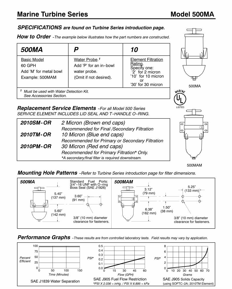
116
Marine Turbine Series
How to Order --The example below illustrates how the part numbers are constructed.
Model 500MA
500MA 10P
1 Must be used with Water Detection Kit.See Accessories Section.
Performance Graphs --These results are from controlled laboratory tests. Field results may vary by application.
0
25
50
75
100
0 50 100 150
SAE J1839 Water Separation
PercentEfficient
Time (Minutes)
3.12”(79 mm)
1.50”(38 mm)
5.25”(133 mm)
3/8” (10 mm) diameterclearance for fasteners.
5.40”(137 mm)
3/8” (10 mm) diameterclearance for fasteners.
3.60”(91 mm)
5.60”(142 mm)
6.38”(162 mm)
Mounting Hole Patterns --Refer to Turbine Series introduction page for filter dimensions.
500MA 500MAM
Replacement Service Elements --For all Model 500 SeriesSERVICE ELEMENT INCLUDES LID SEAL AND T--HANDLE O--RING.
2010SM-OR 2 Micron (Brown end caps)Recommended for Final /Secondary Filtration
2010TM-OR 10 Micron (Blue end caps)Recommended for Primary or Secondary Filtration
2010PM-OR 30 Micron (Red end caps)Recommended for Primary Filtration* Only.*A secondary/final filter is required downstream.
0.00.10.20.30.40.5
0 15 30 45 60
SAE J905 Fuel Flow Restriction*PSI X 2.036 = inHg. / PSI X 6.895 = kPa
Flow (GPH)
PSI*
0
2
4
6
8
0 10 20 30 40 50 60 70
SAE J905 Solids Capacity(using SOFTC--2A; 2010TM Element)
Grams
PSI*
500MA
500MAM
SPECIFICATIONS are found on Turbine Series introduction page.
LISTED
Basic Model60 GPHAdd ’M’ for metal bowlExample: 500MAM
Water Probe.1
Add ’P’ for an in--bowlwater probe.(Omit if not desired).
Element FiltrationRating.Specify one:’2’ for 2 micron’10’ for 10 micron
or’30’ for 30 micron
Standard Fuel Ports:3/4”--16 UNF with O--ringBoss Seal (SAE J1926)

117
Model 500MA
Item Part No. Description Case Qty.
1 RK11888 T--handle 1
11350 T--handle O--ring 10
2 RK15078 Lid 1
3 15005 Lid Gasket 10
4 RK15377--01 Body, 3/4”--16 UNF Ports (MA, effective 1/15/96) 1
RK15082 Body, 9/16”--18 UNF Ports (prior to 1/15/96) 1
5 RK15090 Mounting Bracket, unitized with Bowl Ring (MA) 1
6 15374 Bowl Gasket (supercedes 15009 O--ring--All models) 10
7 RK15013D Turbine Centrifuge / Conical Baffle 1
8 RK15279--01 See--thru Bowl w/ Water Probe Plug, (MA) 1
RK15301--01 Metal Bowl w/1/4”NPT Drain & Water Probe Port 1
9 RK151041 Heat Deflector Shield (MA) 1
10 RK210692 Water Probe Assembly 1
11 RK20022 Metal Water Probe Port Plug 1
12 11340 Drain Fitting O--ring (New Style) 1
13 11041 Bowl Drain Washer (New and Old Style) 10
14 RK19492 Diesel Marine Shut--off Valve Kit. 1
15 RK15300 Mounting Bracket, 3--piece (MAM) 1
16 918--N4 Bowl plug, 1/4” NPT (Old and New Style) 1
17 11--1910 Bowl Drain Fitting (New Style) 1
RK11--1910 Complete Bowl Drain Fitting Kit (New Style) 1
11040 Bowl Drain Fitting (Old Style) 10
18 RK15010B Check Ball w/ Seal 1
19 RK15081--013 Phillips Head Capscrews 10--24 x 1” (4) 1
RK150813 Hex/Washer Head Capscrews 10--24 x 7/8” (4) 1
20 2010SM--OR 2 Micron Element w/ Seals 12
2010TM--OR 10 Micron Element w/ Seals 12
2010PM--OR 30 Micron Element w/ Seals 12
21 RK15079 Return Tube (w/ tapered pipe base threads) 1
22 RK15211 Seal Service Kit (all models-- not shown) 1
15335 Installation Instructions, 500MA
1 For replacement only. The Coast Guard does not accept ’FG’ units
converted to ’MA’ configurations.2 For diesel service only. Must be used with a Water Detection Kit.3 Models built prior to 2/96 use RK15081--01, after 2/96 use RK15081.
( Fuel ports have 1 1/4” square boss on models made after 2/96 ).
4 Units built prior to Fall, 1998.
See Accessories Section.
Marine Turbine Series
FIGURE 1. 500MA Series Cutaway View. The circled number corresponds to the item number shown below.
500MAPModelshown
500MAM 3--Piece Bracket
2
1
21
2
3
4
5
6
7
8
9
12
11
10
13
15
1617
18
19
20
13
Old Style4 New Style
14
1716
Drain Fitting Configurations
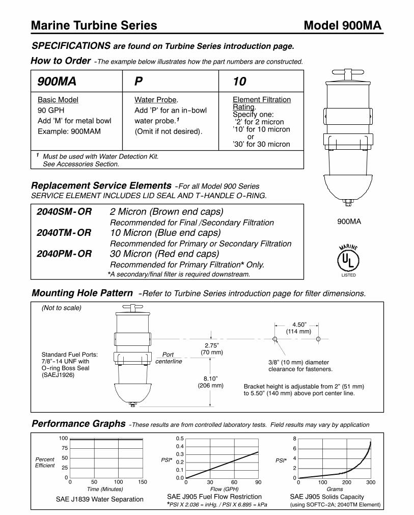
118
Marine Turbine Series
How to Order --The example below illustrates how the part numbers are constructed.
Model 900MA
900MA 10P
1 Must be used with Water Detection Kit.See Accessories Section.
Performance Graphs --These results are from controlled laboratory tests. Field results may vary by application
0
25
50
75
100
0 50 100 150
SAE J1839 Water Separation
PercentEfficient
Time (Minutes)
2.75”(70 mm)
3/8” (10 mm) diameterclearance for fasteners.
4.50”(114 mm)
8.10”(206 mm)
Mounting Hole Pattern --Refer to Turbine Series introduction page for filter dimensions.
(Not to scale)
Replacement Service Elements --For all Model 900 SeriesSERVICE ELEMENT INCLUDES LID SEAL AND T--HANDLE O--RING.
2040SM-OR 2 Micron (Brown end caps)Recommended for Final /Secondary Filtration
2040TM-OR 10 Micron (Blue end caps)Recommended for Primary or Secondary Filtration
2040PM-OR 30 Micron (Red end caps)Recommended for Primary Filtration* Only.*A secondary/final filter is required downstream.
0.00.10.20.30.40.5
0 30 60 90
SAE J905 Fuel Flow Restriction*PSI X 2.036 = inHg. / PSI X 6.895 = kPa
Flow (GPH)
PSI*
0
2
4
6
8
0 100 200 300
SAE J905 Solids Capacity(using SOFTC--2A; 2040TM Element)
Grams
PSI*
SPECIFICATIONS are found on Turbine Series introduction page.
LISTED
900MA
Bracket height is adjustable from 2” (51 mm)to 5.50” (140 mm) above port center line.
Portcenterline
Basic Model90 GPHAdd ’M’ for metal bowlExample: 900MAM
Water Probe.Add ’P’ for an in--bowlwater probe.1
(Omit if not desired).
Element FiltrationRating.Specify one:’2’ for 2 micron’10’ for 10 micron
or’30’ for 30 micron
Standard Fuel Ports:7/8”--14 UNF withO--ring Boss Seal(SAEJ1926)
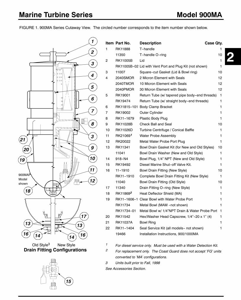
119
Model 900MA
Item Part No. Description Case Qty.1 RK11888 T--handle 1
11350 T--handle O--ring 10
2 RK11005B Lid 1
RK11005B--02 Lid with Vent Port and Plug Kit (not shown) 1
3 11007 Square--cut Gasket (Lid & Bowl ring) 10
4 2040SMOR 2 Micron Element with Seals 12
2040TMOR 10 Micron Element with Seals 12
2040PMOR 30 Micron Element with Seals 12
5 RK19001 Return Tube (w/ tapered pipe body--end threads) 1
RK19474 Return Tube (w/ straight body--end threads) 1
6 RK11815--101 Body Clamp Bracket 1
7 RK19002 Outer Cylinder 1
8 RK11--1679 Plastic Body Plug 1
9 RK11028B Check Ball and Seal 10
10 RK11026D Turbine Centrifuge / Conical Baffle 1
11 RK210691 Water Probe Assembly 1
12 RK20022 Metal Water Probe Port Plug 1
13 RK11341 Bowl Drain Gasket Kit (for New and Old Styles) 10
11041 Bowl Drain Washer (New and Old Style) 1
14 918--N4 Bowl Plug, 1/4” NPT (New and Old Style) 1
15 RK19492 Diesel Marine Shut--off Valve Kit. 1
16 11--1910 Bowl Drain Fitting (New Style) 10
RK11--1910 Complete Bowl Drain Fitting Kit (New Style) 1
11040 Bowl Drain Fitting (Old Style) 10
17 11340 Drain Fitting O--ring (New Style) 1
18 RK118682 Heat Deflector Shield (MA) 1
19 RK11--1606--1 Clear Bowl with Water Probe Port 1
RK11734 Metal Bowl (MAM --not shown) 1
RK11734--01 Metal Bowl w/ 1/4”NPT Drain & Water Probe Port 1
20 RK11542 Hex/Washer Head Capscrew, 1/4”--20 x 1” (4) 1
21 RK11037A Bowl Ring 1
22 RK11--1404 Seal Service Kit (all models-- not shown) 1
19466 Installation Instructions, 900/1000MA
1 For diesel service only. Must be used with a Water Detection Kit.2 For replacement only. The Coast Guard does not accept ’FG’ units
converted to ’MA’ configurations.
3 Units built prior to Fall, 1998
See Accessories Section.
Marine Turbine Series
FIGURE 1. 900MA Series Cutaway View. The circled number corresponds to the item number shown below.
900MAPModelshown
3
4
5
6
3
11
12
13
1
2
21
19
18
20
16
7
8
2
15
9
10
13
1414 16
17
Old Style3 New StyleDrain Fitting Configurations
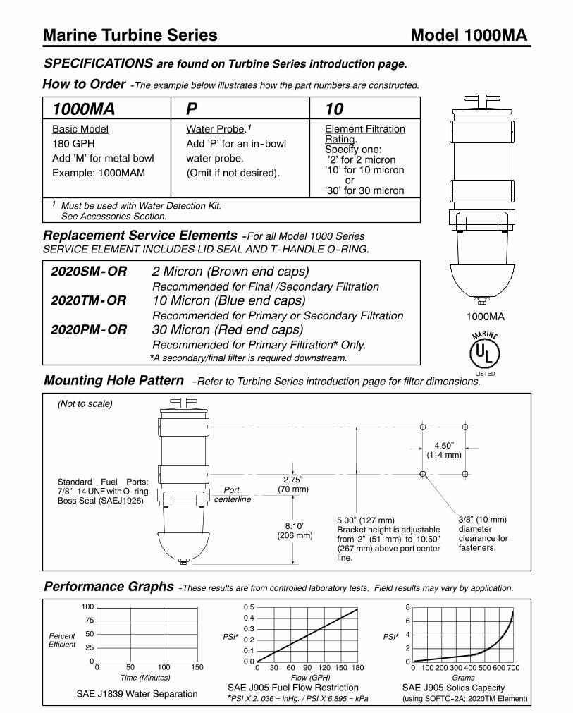
120
Marine Turbine Series
How to Order --The example below illustrates how the part numbers are constructed.
Model 1000MA
1000MA 10P
Performance Graphs --These results are from controlled laboratory tests. Field results may vary by application.
0
25
50
75
100
0 50 100 150
SAE J1839 Water Separation
PercentEfficient
Time (Minutes)
2.75”(70 mm)
3/8” (10 mm)diameterclearance forfasteners.
4.50”(114 mm)
8.10”(206 mm)
Mounting Hole Pattern --Refer to Turbine Series introduction page for filter dimensions.
(Not to scale)
Replacement Service Elements --For all Model 1000 SeriesSERVICE ELEMENT INCLUDES LID SEAL AND T--HANDLE O--RING.
2020SM-OR 2 Micron (Brown end caps)Recommended for Final /Secondary Filtration
2020TM-OR 10 Micron (Blue end caps)Recommended for Primary or Secondary Filtration
2020PM-OR 30 Micron (Red end caps)Recommended for Primary Filtration* Only.*A secondary/final filter is required downstream.
0.00.10.20.30.40.5
0 30 60 90 120 150 180
SAE J905 Fuel Flow Restriction*PSI X 2. 036 = inHg. / PSI X 6.895 = kPa
Flow (GPH)
PSI*
0
2
4
6
8
0 100 200 300 400 500 600 700
SAE J905 Solids Capacity(using SOFTC--2A; 2020TM Element)
Grams
SPECIFICATIONS are found on Turbine Series introduction page.
LISTED
1000MA
5.00” (127 mm)Bracket height is adjustablefrom 2” (51 mm) to 10.50”(267 mm) above port centerline.
Portcenterline
PSI*
Basic Model180 GPHAdd ’M’ for metal bowlExample: 1000MAM
Water Probe.1
Add ’P’ for an in--bowlwater probe.(Omit if not desired).
Element FiltrationRating.Specify one:’2’ for 2 micron’10’ for 10 micron
or’30’ for 30 micron
1 Must be used with Water Detection Kit.See Accessories Section.
Standard Fuel Ports:7/8”--14UNFwithO--ringBoss Seal (SAEJ1926)

121
Model 1000MA
Item Part No. Description Case Qty.
1 RK11888 T--handle 1
11350 T--handle O--ring 10
2 RK11005B Lid 1
RK11005B--02 Lid with Vent Port and Plug Kit (not shown) 1
3 11007 Square--cut Gasket (Lid & Bowl ring) 10
4 RK11815--101 Body Clamp Bracket 1
5 2020SMOR 2 Micron Element with Seals 12
2020TMOR 10 Micron Element with Seals 12
2020PMOR 30 Micron Element with Seals 12
6 RK11008 Return Tube (w/ tapered pipe body--end threads) 1
RK11--1775 Return Tube (w/ straight body--end threads) 1
7 RK11021 Outer Cylinder 1
8 RK11--1679 Plastic Body Plug 1
9 RK11028B Check Ball and Seal 10
10 RK11026D Turbine Centrifuge / Conical Baffle 1
11 RK210691 Water Probe (MA Bowls) 1
12 RK20022 Metal Water Probe Port Plug 1
13 RK11341 Bowl Drain Gasket Kit (for New and Old Styles) 10
11041 Bowl Drain Washer (New and Old Style) 1
14 918--N4 Bowl Plug, 1/4” NPT (New and Old Style) 1
15 RK19492 Shut--off Drain Valve Kit (for diesel use, only) 1
16 11--1910 Bowl Drain Fitting (New Style) 10
RK11--1910 Complete Bowl Drain Fitting Kit (New Style) 1
11040 Bowl Drain Washer (Old Style) 10
17 11340 Drain Fitting O--ring (New Style) 1
18 RK118682 Heat Deflector Shield (MA) 1
19 RK11--1606--1 Clear Bowl with Water Probe Port 1
RK11734 Metal Bowl (MAM --not shown) 1
RK11734--01 Metal Bowl w/ 1/4”NPT Drain & Water Probe Port 1
20 RK11542 Hex/Washer Head Capscrew, 1/4”--20 x 1” (4) 1
21 RK11037A Bowl Ring 1
22 RK11--1404 Seal Service Kit (all models-- not shown) 1
19466 Installation Instructions, 900/1000MA
1 For diesel service only. Must be used with a Water Detection Kit.2 For replacement only. The Coast Guard does not accept ’FG’ units
converted to ’MA’ configurations.
3 Units built prior to Fall, 1998
See Accessories Section.
Marine Turbine Series
FIGURE 1. 1000MA Series Cutaway View. The circled number corresponds to the item number shown below.
1000MAPModel shown
3
5
6
3
10
11
12
1 2
21
19
18
20
4
7
8
2
9
15
13
16
13
1414 16
17
Old Style3 New StyleDrain Fitting Configurations

122
Marine Turbine Series
How to Order --The example below illustrates how the part numbers are constructed.
Model 73/1000MA
73/1000MA 10P
Performance Graphs --These results are from controlled laboratory tests. Field results may vary by application.
0
25
50
75
100
0 50 100 150
SAE J1839 Water Separation
PercentEfficient
Time (Minutes)
2.50”(64 mm)
3/8” (10 mm) diameterclearance for fasteners.
4.50”(114 mm)
8.10”(206 mm)
Mounting Hole Pattern --Refer to Turbine Series introduction page for filter dimensions.
Replacement Service Elements --Order two (2) per unit.SERVICE ELEMENT INCLUDES LID SEAL AND T--HANDLE O--RING.
2020SM-OR 2 Micron (Brown end caps)Recommended for Final /Secondary Filtration
2020TM-OR 10 Micron (Blue end caps)Recommended for Primary or Secondary Filtration
2020PM-OR 30 Micron (Red end caps)Recommended for Primary Filtration* Only.*A secondary/final filter is required downstream.
0.0
0.5
1.0
1.5
2.0
0 60 120 180 240 300 360
SAE J905 Fuel Flow Restriction*PSI X 2.036 = inHg. / PSI X 6.895 = kPa
Flow (GPH)
PSI*
0
2
4
6
8
0 250 500 750 10001250
SAE J905 Solids Capacity(using SOFTC--2A; 2020TM Element)
Grams
SPECIFICATIONS are found on Turbine Series introduction page.
LISTED
73/1000MA
12.00”(305 mm)
INLET
1.75”(45 mm)
OUTLET
(Not to scale)
PSI*
Standard FuelInlet / Outlet:3/4”--14 NPT
Basic Model360 GPHAdd ’M’ for metal bowlExample: 73/1000MAM
Water Probe.1
Add ’P’ for an in--bowlwater probe.(Omit if not desired).
Element FiltrationRating.Specify one:’2’ for 2 micron’10’ for 10 micron
or’30’ for 30 micron
1 For use with Water Detection Kit only.See Accessories Section.
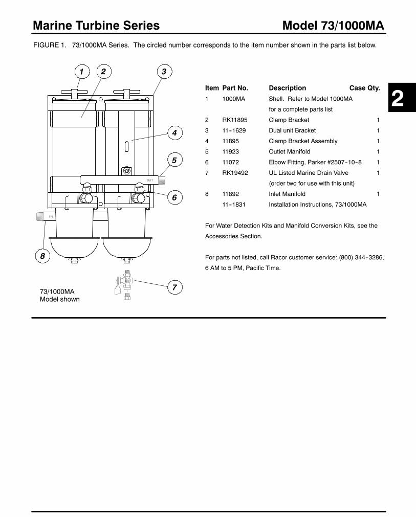
123
Model 73/1000MA
Item Part No. Description Case Qty.
1 1000MA Shell. Refer to Model 1000MA
for a complete parts list
2 RK11895 Clamp Bracket 1
3 11--1629 Dual unit Bracket 1
4 11895 Clamp Bracket Assembly 1
5 11923 Outlet Manifold 1
6 11072 Elbow Fitting, Parker #2507--10--8 1
7 RK19492 UL Listed Marine Drain Valve 1
(order two for use with this unit)
8 11892 Inlet Manifold 1
11--1831 Installation Instructions, 73/1000MA
For Water Detection Kits and Manifold Conversion Kits, see the
Accessories Section.
For parts not listed, call Racor customer service: (800) 344--3286,
6 AM to 5 PM, Pacific Time.
Marine Turbine SeriesFIGURE 1. 73/1000MA Series. The circled number corresponds to the item number shown in the parts list below.
73/1000MAModel shown
5
6
1 2
8
2
7
4
3
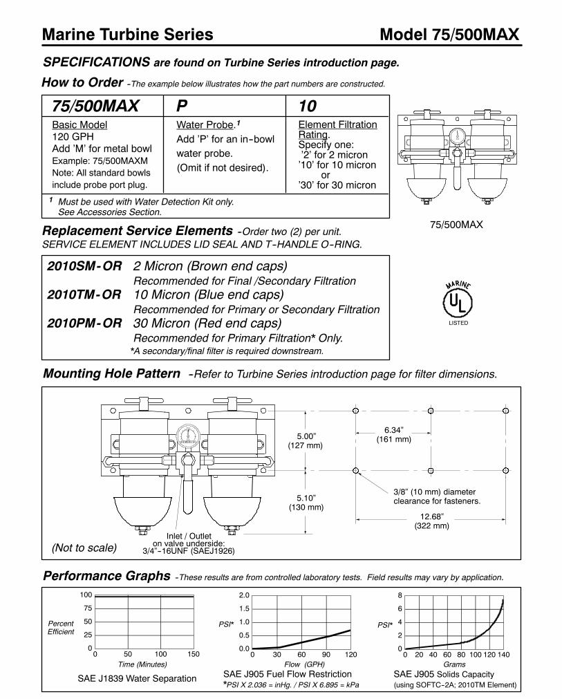
124
Marine Turbine Series
How to Order --The example below illustrates how the part numbers are constructed.
Model 75/500MAX
75/500MAX 10P
Performance Graphs --These results are from controlled laboratory tests. Field results may vary by application.
0
25
50
75
100
0 50 100 150
SAE J1839 Water Separation
PercentEfficient
Time (Minutes)
3/8” (10 mm) diameterclearance for fasteners.
12.68”(322 mm)
5.10”(130 mm)
Mounting Hole Pattern --Refer to Turbine Series introduction page for filter dimensions.
(Not to scale)
Replacement Service Elements --Order two (2) per unit.SERVICE ELEMENT INCLUDES LID SEAL AND T--HANDLE O--RING.
2010SM-OR 2 Micron (Brown end caps)Recommended for Final /Secondary Filtration
2010TM-OR 10 Micron (Blue end caps)Recommended for Primary or Secondary Filtration
2010PM-OR 30 Micron (Red end caps)Recommended for Primary Filtration* Only.*A secondary/final filter is required downstream.
0.0
0.5
1.0
1.5
2.0
0 30 60 90 120
SAE J905 Fuel Flow Restriction*PSI X 2.036 = inHg. / PSI X 6.895 = kPa
Flow (GPH)
PSI*
0
2
4
6
8
0 20 40 60 80 100 120 140
SAE J905 Solids Capacity(using SOFTC--2A; 2010TM Element)
Grams
PSI*
SPECIFICATIONS are found on Turbine Series introduction page.
LISTED
75/500MAX
5.00”(127 mm)
6.34”(161 mm)
Basic Model120 GPHAdd ’M’ for metal bowlExample: 75/500MAXMNote: All standard bowlsinclude probe port plug.
Water Probe.1
Add ’P’ for an in--bowlwater probe.(Omit if not desired).
Element FiltrationRating.Specify one:’2’ for 2 micron’10’ for 10 micron
or’30’ for 30 micron
1 Must be used with Water Detection Kit only.See Accessories Section.
Inlet / Outleton valve underside:
3/4”--16UNF (SAEJ1926)

125
Model 75/500MAX
Item Part No. Description Case Qty.
1 500MA Shell. Refer to Model 500MA
for a complete parts list
2 RK15329 Main Bracket (will not accommodate
piece body clamp brackets) 1
3 RK19476 Gauge Assembly 1
4 RK15378 Body Clamp Bracket, One--Piece 1
RK15300 Body Clamp Bracket, Three--Piece
(See illustration below) 1
5 RK15344 Rigid Tubing Assembly 1
6 RK15321 Valve Assembly 1
RK15389 Valve Service Kit 1
7 RK19492 UL Listed Marine Drain Valve
(order two for use with this unit) 1
15350 Installation Instructions, 75/500MAX
For Fuel Port Adapter Fittings, Water Detection Kits and Manifold
Conversion Kits, see the Accessories Section.
For parts not listed, call Racor customer service: (800) 344--3286.
Marine Turbine Series
FIGURE 1. 75/500MAX Series. The circled number corresponds to the item number shown in the parts list below.
75/500MAXModel shown
2
5
1 2
6
4
3
7
4
RK15300 Three--piece bracket

126
Marine Turbine Series
How to Order --The example below illustrates how the part numbers are constructed.
Model 75/900MAX
75/900MAX 10P
Performance Graphs --These results are from controlled laboratory tests. Filter results may vary by application.
0
25
50
75
100
0 50 100 150
SAE J1839 Water Separation
PercentEfficient
Time (Minutes)
11.00”(279 mm)
Mounting Hole Pattern --Refer to Turbine Series introduction page for filter dimensions.
(Not to scale)
Replacement Service Elements --Order two (2) per unit.SERVICE ELEMENT INCLUDES LID SEAL AND T--HANDLE O--RING.
2040SM-OR 2 Micron (Brown end caps)Recommended for Final /Secondary Filtration
2040TM-OR 10 Micron (Blue end caps)Recommended for Primary or Secondary Filtration
2040PM-OR 30 Micron (Red end caps)Recommended for Primary Filtration* Only.*A secondary/final filter is required downstream.
0.0
0.5
1.0
1.5
2.0
0 60 120 180
SAE J905 Fuel Flow Restriction*PSI X 2.036 = inHg. / PSI X 6.895 = kPa
Flow (GPH)
PSI*
0
2
4
6
8
0 100 200 300 400 500 600
SAE J905 Solids Capacity(using SOFTC--2A; 2040TM Element)
Grams
PSI*
SPECIFICATIONS are found on Turbine Series introduction page.
LISTED
75/900MAX
3.50”(89 mm)
17.63”(448 mm)
Basic Model180 GPHAdd ’M’ for metal bowlExample: 75/900MAXM
Water Probe.1
Add ’P’ for an in--bowlwater probe.(Omit if not desired).
Element FiltrationRating.Specify one:’2’ for 2 micron’10’ for 10 micron
or’30’ for 30 micron
1 Must be used with Water Detection Kit only.See Accessories Section.
Inlet / Outlet:On valve underside.See Note at Right.
NOTE: The Inlet / Outlet Port Male Fittings are7/8”--14UNF threads with 37_ Flare (JIC);SAEJ514. These permanent fittings must notbe removed. Damage to the valve may result.See fittingsselectionchart inAccessoriesSectionto adapt to your fuel system piping requirements.
3/8” (10 mm) diameterclearance for fasteners.

127
Model 75/900MAX
Item Part No. Description Case Qty.
1 900MA Shell. Refer to Model 900MA
for a complete parts list
2 RK19476 Gauge Assembly 1
3 RK19486 Dual unit Bracket 1
4 RK19475 Rigid Tubing Assembly 1
5 RK19492 UL Listed Marine Drain Valve
(order two for use with this unit) 1
6 RK19473 Valve Assembly 1
RK19506 Valve Service Kit 1
19485 Installation Instructions, 75/900MAX
For Fuel Port Adapter Fittings, Water Detection Kits and Manifold
Conversion Kits, see the Accessories Section.
For parts not listed, call Racor customer service: (800) 344--3286,
6 AM to 5 PM, Pacific Time.
Marine Turbine Series
FIGURE 1. 75/900MAX Series. The circled number corresponds to the item number shown in the parts list below.
75/900MAX Model shown
4
1
6
2 3
2
5
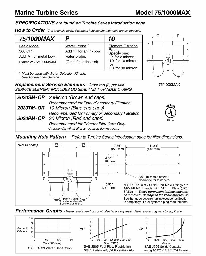
128
Marine Turbine Series
How to Order --The example below illustrates how the part numbers are constructed.
Model 75/1000MAX
75/1000MAX 10P
Performance Graphs --These results are from controlled laboratory tests. Field results may vary by application.
0
25
50
75
100
0 50 100 150
SAE J1839 Water Separation
PercentEfficient
Time (Minutes)
Mounting Hole Pattern --Refer to Turbine Series introduction page for filter dimensions.
Replacement Service Elements --Order two (2) per unit.SERVICE ELEMENT INCLUDES LID SEAL AND T--HANDLE O--RING.
2020SM-OR 2 Micron (Brown end caps)Recommended for Final /Secondary Filtration
2020TM-OR 10 Micron (Blue end caps)Recommended for Primary or Secondary Filtration
2020PM-OR 30 Micron (Red end caps)Recommended for Primary Filtration* Only.*A secondary/final filter is required downstream.
012345
0 60 120 180 240 300 360
SAE J905 Fuel Flow Restriction*PSI X 2.036 = inHg. / PSI X 6.895 = kPa
Flow (GPH)
PSI*
0
2
4
6
8
0 300 600 900 1200
SAE J905 Solids Capacity(using SOFTC--2A; 2020TM Element)
Grams
PSI*
SPECIFICATIONS are found on Turbine Series introduction page.
LISTED
75/1000MAX
17.63”(448 mm)
(Not to scale)
Basic Model360 GPHAdd ’M’ for metal bowlExample: 75/1000MAXM
Water Probe.1
Add ’P’ for an in--bowlwater probe.(Omit if not desired).
Element FiltrationRating.Specify one:’2’ for 2 micron’10’ for 10 micronor’30’ for 30 micron
1 Must be used with Water Detection Kit only.See Accessories Section.
3/8” (10 mm) diameterclearance for fasteners.
NOTE: The Inlet / Outlet Port Male Fittings are7/8”--14UNF threads with 37_ Flare (JIC);SAEJ514. These permanent fittings must notbe removed. Damage to the valve may result.See fittingsselectionchart inAccessoriesSectionto adapt to your fuel system piping requirements.
10.50”(267 mm)
3.88”(98 mm)
7.75”(279 mm)
Inlet / Outlet:On valve underside.See Note at Right.

129
Model 75/1000MAX
Item Part No. Description Case Qty.
1 1000MA Shell. Refer to Model 1000MA
for a complete parts list
2 RK19476 Gauge Assembly 1
3 RK11--1777 Dual unit Bracket 1
4 RK19475 Rigid Tubing Assembly 1
5 RK19492 UL Listed Marine Drain Valve
(order two for use with this unit) 1
6 RK19473 Valve Assembly 1
RK19506 Valve Service Kit 1
19485 Installation Instructions, 75/1000MAX
For Fuel Port Adapter Fittings, Water Detection Kits and Manifold
Conversion Kits, see the Accessories Section.
For parts not listed, call Racor customer service: (800) 344--3286,
6 AM to 5 PM, Pacific Time.
Marine Turbine Series
FIGURE 1. 75/1000MAX Series. The circled number corresponds to the item number shown in the parts list below.
75/1000MAX Model shown
4
1
6
2 3
2
5

130
Marine Turbine Series
How to Order --The example below illustrates how the part numbers are constructed.
Model 77/1000MA
77/1000MA 10P
Performance Graphs --These results are from controlled laboratory tests. Field results may vary by application.
0
25
50
75
100
0 50 100 150
SAE J1839 Water Separation
PercentEfficient
Time (Minutes)
2.50”(64 mm)
3/8”(10 mm)diameterclearanceforfasteners.
5.94”(151 mm)
8.10”(206 mm)
Mounting Hole Pattern --Refer to Turbine Series introduction page for filter dimensions.
Replacement Service Elements --Order three (3) per unit.SERVICE ELEMENT INCLUDES LID SEAL AND T--HANDLE O--RING.
2020SM-OR 2 Micron (Brown end caps)Recommended for Final /Secondary Filtration
2020TM-OR 10 Micron (Blue end caps)Recommended for Primary or Secondary Filtration
2020PM-OR 30 Micron (Red end caps)Recommended for Primary Filtration* Only.*A secondary/final filter is required downstream.
0.0
0.5
1.0
1.5
2.0
0 90 180 270 360 450 540
SAE J905 Fuel Flow Restriction*PSI X 2.036 = inHg. / PSI X 6.895 = kPa
Flow (GPH)
PSI*
0
2
4
6
8
0 500 1000 1500 2000
SAE J905 Solids Capacity(using SOFTC--2A; 2020TM Element)
Grams
PSI*
SPECIFICATIONS are found on Turbine Series introduction page.
LISTED
77/1000MA
INLET
1.75”(45 mm)
17.75”(451 mm)
12.75”(324 mm)
(Not to scale)
Inlet / Outlet:1”--11 1/2 NPT
Basic Model540 GPHAdd ’M’ for metal bowlExample: 77/1000MAM
Water Probe.1
Add ’P’ for an in--bowlwater probe.(Omit if not desired).
Element FiltrationRating.Specify one:’2’ for 2 micron’10’ for 10 micron
or’30’ for 30 micron
1 Must be used with Water Detection Kit only.See Accessories Section.
OUTLET

131
Model 77/1000MA
Item Part No. Description Case Qty.
1 1000MA Shell. Refer to Model 1000MA
for a complete parts list
2 11--1632 Triple unit Bracket 1
3 11895 Clamp Bracket Assembly 1
4 RK11895 Clamp Bracket 1
5 11902 Outlet Manifold 1
6 11072 Elbow Fitting, Parker #2507--10--8 1
7 RK19492 UL Listed Marine Drain Valve
(order three for use with this unit) 1
8 11893 Inlet Manifold 1
11--1831 Installation Instructions, 77/1000MA
For Water Detection Kits and Manifold Conversion Kits, see the
Accessories Section.
For parts not listed, call Racor customer service: (800) 344--3286,
6 AM to 5 PM, Pacific Time.
Marine Turbine Series
FIGURE 1. 77/1000MA Series. The circled number corresponds to the item number shown in the parts list below.
77/1000MA Model shown
5
6
1 2
7
4
2
8
3

132
Marine Turbine Series
How to Order --The example below illustrates how the part numbers are constructed.
Model 79/1000MAV
79/1000MAV 10P
Performance Graphs --These results are from controlled laboratory tests. Field results may vary by application.
0
25
50
75
100
0 50 100 150
SAE J1839 Water Separation
PercentEfficient
Time (Minutes)
3/8”(10 mm)diameterclearanceforfasteners.
8.00”(203 mm)
Mounting Hole Pattern --Refer to Turbine Series introduction page for filter dimensions.
Replacement Service Elements --Order three (3) per unit.SERVICE ELEMENT INCLUDES LID SEAL AND T--HANDLE O--RING.
2020SM-OR 2 Micron (Brown end caps)Recommended for Final /Secondary Filtration
2020TM-OR 10 Micron (Blue end caps)Recommended for Primary or Secondary Filtration
2020PM-OR 30 Micron (Red end caps)Recommended for Primary Filtration* Only.*A secondary/final filter is required downstream.
0
1
2
3
0 90 180 270 360 450 540
SAE J905 Fuel Flow Restriction*PSI X 2.036 = inHg. / PSI X 6.895 = kPa
Flow ( GPH)
PSI*
0
2
4
6
8
0 300 600 900 1200
SAE J905 Solids Capacity(using SOFTC--2A; 2020TM Element)
Grams
PSI*
SPECIFICATIONS are found on Turbine Series introduction page.
LISTED
79/1000MAV
INLET
5.94”(151 mm)
17.75”(451 mm)
12.75”(324 mm)OUTLET
5.50”(140 mm)
(Not to scale)Inlet / Outlet:3/4”--14 NPT
Basic Model540 GPHAdd ’M’ for metal bowlExample: 79/1000MAVM
Water Probe.1
Add ’P’ for an in--bowlwater probe.(Omit if not desired).
Element FiltrationRating.Specify one:’2’ for 2 micron’10’ for 10 micron
or’30’ for 30 micron
1 For use with Water Detection Kit only.See Accessories Section.

133
Model 79/1000MAV
Item Part No. Description Case Qty.
1 1000MA Shell. Refer to Model 1000MA
for a complete parts list
2 11--1632 Triple unit Bracket 1
3 11895 Clamp Bracket 1
4 11--1761 ’U’ Bracket 1
5 19461 Outlet Manifold 1
6 RK11073 1/2” Ball Valve 1
7 11--1626 Formed Tubing Assembly 1
8 RK19492 UL Listed Marine Drain Valve
(order three for use with this unit) 1
9 19460 Inlet Manifold 1
11--1821 Installation Instructions, 79/1000MAV
For Water Detection Kits and Manifold Conversion Kits, see the
Accessories Section.
For parts not listed, call Racor customer service: (800) 344--3286,
6 AM to 5 PM, Pacific Time.
Marine Turbine Series
FIGURE 1. 79/1000MAV Series. The circled number corresponds to the item number shown in the parts list below.
79/1000MAV Model shown
5
6
1 2
7
3
9
4 2
8

142
Marine Fuel / Air Separators
Specifications
Model Illustrations
Special Notes
1. Exercise caution to avoid fuel splash if fueling nozzle is not equipped with automatic shut--off capability.Wrap an absorbant cloth around fill port/nozzle to ensure no spillage.
2. Order Adapter Kit No. RK50033 (1/2”NPTF fittings) to accommodate all other vent line hose sizes.3. UL Listing pending, meets U.S.C.G. pleasure craft requirements.4. For additional information and availability, contact customer service at: (800) 344--3286, 6 AM to 5 PM, Pacific Time.
LG100LG50
BASIC MODELS LG50 LG100
Fuel type Gasoline Diesel/Gasoline
Maximum Flow CapacityCubic feet (air) per minute (CFM) 12 17Gallons per minute (GPM) 90 127Liters per minute (LPM) 341 481
Hose fitting size, I.D. 5/8” 5/8”Optional adapter RK50033 1/2”NPTF 1/2”NPTF
Height in. 6 9 3/4mm 152.4 247.7
Diameter in. 1 3/4 4mm 44.5 101.6
Weight (dry) lbs. 1.2 1.62kgs. 0.54 0.73
Operating Temperature --40o / +255o F / --40o / +121o C
1. GASOLINE Model LG50 The fill flow rate capacity is 12 cubic feet (air) per minute (90 GPM) and can handle mostcommercial fuel dispensing nozzles. The vent line connections are for standard 5/8” I.D. rubber hose.
2. DIESEL OR GASOLINE FUEL Model LG100 The fill flow rate capacity is 17 cubic feet (air) per minute (127 GPM)and handles commercial fuel dispensing nozzles. The vent line connections are for standard 5/8” I.D. rubber hose.
Selection Information
Introduction

143
Marine Fuel / Air Separators Models LG50 & LG100
SPECIFICATIONS are found on Fuel / Air Separator introduction page.
LG50: 1. In the First Stage theventing tank fuel is diffused by theFlow Diverter. Air is allowed tobypass the diverter but fuel isdirected back to the tank.
2. In the Second Stage, vaporcollects on the interior surfacesand coalesces. The fuel returnsdownward by gravity and aircontinues up and out of the unit.
The Safety Relief Valve includesa floating check ball which will notpermit a large in--rush of fuel tobypass. In the event of internalpressure reaching 2.4 PSI, thespring will compress and openthe safety seat.
From fuel tank.
UP, To vent
How the Lifeguard WorksLG50
The LG50 has no serviceable parts. See the Parts List below for fitting alternatives:
Part No. Description Qty.RK50021 LG100 Replacement screen, spring, check ball & seals. 1RK50023 LG100 2--piece Steel Mounting Bracket (not shown) 1
RK50033 Straight Fitting Adapter, 1/2” NPT female (not shown) 1RK50003 Elbow Fitting, 5/8” hose barb (see view at right) 1
TroubleshootingINSPECT FUEL SYSTEM COMPONENTS AND THE OVERBOARD VENT OF OBSTRUCTIONS, ANNUALLY.
These units must be installed vertically (or up to 60_ from vertical) in the vent line with the arrow pointingUP (towards vent).Do not allow loops or low spots where fuel may pool. Flying insects may build nests in vent ports which may alsoobstruct the escaping vapors. These situations may be evident by premature tripping of the fuel nozzle automaticshut--off during refueling or constant fuel filling splash--ups.
In the event of severe fuel tank biological contamination, the units may be fouled and require inspection or cleaning.To disassemble, simply unthread the fittings from the housing and clean only in a fresh solvent bath. Coat the sealswith motor oil and reassemble the unit in reverse order.
LG50 & LG100LG50: 12 CFM, Gasoline.LG100: 17 CFM Gasoline &Diesel Applications.Each unit includes standard5/8” male hose barbs, hoseclamps and instructions.
FEATURES-- Meets USCG pleasure craft requirements.-- Allows fuel tank top--off without overboard spillage.-- Prevents overboard spillage due to agitation.-- Saves fuel costs and prevents possible fines.-- Contains thermal expansion up to 2.4 PSI.-- Prevents maintenance due to fuel stains on vessel.
General Information
2
Note: Use only one elbow fitting with each unitas fitting orientation is random. (Two elbowfittingsmaynotpoint to thedirections youwish).
1
2
LG100: 1. In the First Stage theventing tank fuel is deflected bythe Flow Diverter. Fuel is directeddown to the drain ports and air isallowed to bypass and continuetraveling up.2. The Second Stage defoamsthe fuel through a fine wire meshscreen which filters out largecontaminants. Under the screen,the fuel collects temporarily untilit can flow back down to the fueltank.3. In the Third Stage, vaporcollects on the interior surfacesand coalesces. The fuel returnsdownward by gravity and aircontinues up and out of the unit.The Safety Relief Valve includesa floating check ball which will notpermit a large in--rush of fuel tobypass. In the event of internalpressure reaching 2.4 PSI, thespring will compress and openthe safety seat.
Cutaway viewsare not to scale
LG100
1
3
2
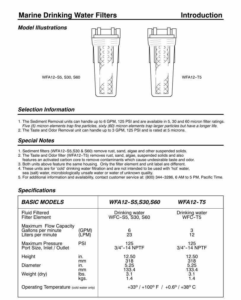
144
Marine Drinking Water Filters
Specifications
Model Illustrations
Special Notes
1. Sediment filters (WFA12--S5,S30 & S60) remove rust, sand, algae and other suspended solids.2. The Taste and Odor filter (WFA12--T5) removes rust, sand, algae, suspended solids and alsofeatures an activated carbon core to remove contaminants which cause undesirable taste and odor.
3. Both units above feature the same housing. Only the filter element and unit label are different.4. These units are for ’cold’ drinking water filtration and are not intended to be used with ’hot’ water,sea (salt) water, microbiologically unsafe water or water of unknown quality.
5. For additional information and availability, contact customer service at: (800) 344--3286, 6 AM to 5 PM, Pacific Time.
WFA12--S5, S30, S60
BASIC MODELS WFA12-S5,S30,S60 WFA12-T5
Fluid Filtered Drinking water Drinking waterFilter Element WFC--S5, S30, S60 WFC--T5
Maximum Flow CapacityGallons per minute (GPM) 6 3Liters per minute (LPM) 23 12
Maximum Pressure PSI 125 125Port Size, Inlet / Outlet 3/4”--14 NPTF 3/4”--14 NPTF
Height in. 12.50 12.50mm 318 318
Diameter in. 5.25 5.25mm 133.4 133.4
Weight (dry) lbs. 3.1 3.1kgs. 1.4 1.4
Operating Temperature (cold water only) +33o / +100o F / +0.6o / +38o C
WFA12--T5
Selection Information
1. The Sediment Removal units can handle up to 6 GPM, 125 PSI and are available in 5, 30 and 60 micron filter ratings.Five (5) micron elements trap fine particles, sixty (60) micron elements trap larger particles but have a longer life.
2. The Taste and Odor Removal unit can handle up to 3 GPM, 125 PSI and is rated at 5 microns.
Introduction

145
Marine Drinking Water Filters
WFA12For cold water filtration only. WFA12 is
the basic model and includes mounting
head, cartridge and transparent sump.Flow Rates: with T5 element: 3 GPM/
180GPH, all others: 6 GPM/360 GPH.
NOTE: The Water Filter may be supported byrigid pipe or tubing. Use the above dimensionsif using the optional mounting bracket.
Mounting Hole Pattern
Replacement Cartridges --Service cartridges DO NOT include head seal.
Filtration / Removal Type Rating.Specify one:-T5 for 5 Micron / Taste & Odor.-S5 for 5 Micron / Sediment.-S30 for 30 Micron / Sediment.-S60 for 60 Micron / Sediment.
SPECIFICATIONS are found on Drinking Water Filter Series introduction page.
2.25”(57 mm)11.50” (292 mm)
Port center linesto bottom.
The circled number corresponds to the item number shown in the parts list below.Parts List
1
Item/Part No. Description Case Qty.1. WFH12 Water Filter Head/Sump (new design) 62. WF--037 Head/Sump Seal (new design) 13. WFC--T5 5 Micron Taste and Odor Cartridge 20
Maximum flow rate is 3 GPM / 180 GPHWFC--S5 5 Micron Sediment Cartridge 20
Maximum flow rate is 6 GPM / 360 GPHWFC--S30 30 Micron Sediment Cartridge 20
Maximum flow rate is 6 GPM / 360 GPHWFC--S60 60 Micron Sediment Cartridge 20
Maximum flow rate is 6 GPM / 360 GPH4. WF--035 Optional Mounting Bracket Kit 15. WF--039 Optional Bowl Wrench (new design) 16. WF--010 Optional Bowl Wrench (old design) 17. WF--009 Head/Sump Seal (old design) 1For parts not listed, call Racor customer service: 800/344--3286, PT.
Head Ports are3/4”--14 NPTF
Model WFA12
WFA12--T5WFA12--S5WFA12--S30WFA12--S60
-S30
WFC-T5 5 Micron, Taste and Odor Removal CartridgeWFC-S5 5 Micron, Sediment Removal CartridgeWFC-S30 30 Micron, Sediment Removal CartridgeWFC-S60 60 Micron, Sediment Removal Cartridge
3
How to Order --The example below illustrates how the part numbers are constructed.
3/8” (9.5 mm) diameterclearance for fasteners.
4
6
Note: Allow 2” (51 mm)below the unit for servicing.
(Not to scale)
--Refer to Drinking Water Filters introduction page for filter dimensions.
2
2
Filter design priorto June 1, 1998
5
7
3

146
Marine Air Filtration
Specifications
BASIC MODELS AF M408512 AF M501012 AF M601212
Max. Air Flow* CFM 800 1200 1600L/s 377.6 566.4 755.2
Outlet Diameter in. 4.00 5.00 6.00mm 101.6 127.0 152.4
Filter Element AF M8040 AF M8050 AF M8060
Length in. 12.50 12.50 12.50mm 317.5 317.5 317.5
Depth in. 9.59 11.14 13.51mm 243.5 282.8 343.2
Hose Barb size in. 1.00 1.25 1.25mm 25.4 25.4 31.75
Weight (dry) Lbs. 4.16 5.03 8.00kgs. 1.89 2.28 3.63
Operating Temperature --40o / +240o F / --40o / +116o C
* Values given are cubic feet per minute (CFM) and liters per second (L/s).
Model Illustrations
Special Notes
1. For additional information and availability, contact customer service at: (800) 344--3286, 6 AM to 5 PM, Pacific Time.
Introduction
AF M601212AF M501012AF M408512
Marine Air Filters/Silencers
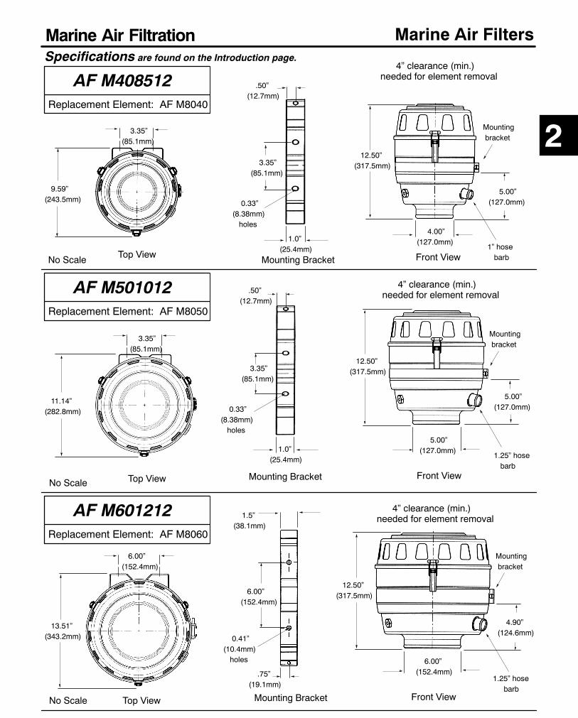
147
Marine Air Filters
AF M501012Replacement Element: AF M8050
Top View
No Scale
Specifications are found on the Introduction page.
Marine Air Filtration
11.14”(282.8mm)
3.35”(85.1mm)
.50”(12.7mm)
12.50”(317.5mm)
No Scale
5.00”(127.0mm)1.0”
(25.4mm)
4” clearance (min.)needed for element removal
5.00”(127.0mm)
1.25” hosebarb
Mountingbracket
3.35”(85.1mm)
0.33”(8.38mm)holes
Mounting Bracket Front View
AF M408512Replacement Element: AF M8040
AF M601212Replacement Element: AF M8060
No Scale
Front View
4.90”(124.6mm)
Mountingbracket
1.25” hosebarb
6.00”(152.4mm)
12.50”(317.5mm)
Mounting Bracket
1.5”(38.1mm)
.75”(19.1mm)
6.00”(152.4mm)
0.41”(10.4mm)holes
Top View
13.51”(343.2mm)
6.00”(152.4mm)
4” clearance (min.)needed for element removal
4” clearance (min.)needed for element removal
12.50”(317.5mm)
4.00”(127.0mm)
5.00”(127.0mm)
1” hosebarb
Mountingbracket
Front View
3.35”(85.1mm)
.50”(12.7mm)
0.33”(8.38mm)holes
1.0”(25.4mm)
Mounting Bracket
9.59”(243.5mm)
3.35”(85.1mm)
Top View
2
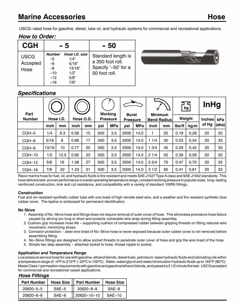
148
Marine Accessories HoseUSCG--rated hose for gasoline, diesel, lube oil, and hydraulic systems for commercial and recreational applications.
How to Order:
CGH -- 5 -- 50USCGAcceptedHose
Standard length isa 350 foot roll.Specify ’--50’ for a50 foot roll.
Specifications
CGH--5
Hose I.D.
Number Hose I.D. size--5 1/4”--6 5/16”--8 13/16”--10 1/2”--12 5/8”--16 7/8”
Hose O.D.WorkingPressure
PartNumber
inch mm
BurstPressure
MinimumBend Radius Weight
inch mm mmpsi psi inchMPa MPa lbs/ft kg/m
Inchesof Hg
kPa(abs)
kg InHg
CGH--6
CGH--8
CGH--10
CGH--12
CGH--16Racormarine hose for fuel, oil, and hydraulic fluids is fire resistant andmeets SAE J1527 Type A class andSAE J1942 standards. Thishosedelivers test--provenperformance inawideoperating temperature range,constantworkingpressure inpopularsizes, long--lastingreinforced construction, kink and cut resistance, and compatibility with a variety of standard 100R5 fittings.
ConstructionFuel and oil--resistant synthetic rubber tube with one braid of high--tensile steel wire, and a weather and fire resistant synthetic bluerubber cover. The layline is embossed for permanent identification.
No Skive1. Assembly of No--Skive hose and fittings does not require removal of outer cover of hose. This eliminates premature hose failure
caused by skiving too long or short and protects vulnerable wire wrap during fitting assembly.2. Cushion grip increases hose life -- supporting cushion of compressed rubber between gripping threads on fitting reduces wire
movement, minimizing stress.3. Corrosion protection -- steel wire braid of No--Skive hose is never exposed because outer rubber cover is not removed before
assembling fitting.4. No--Skive fittings are designed to allow socket threads to penetrate outer cover of hose and grip the wire braid of the hose.5. Simple two step assembly -- attached socket to hose, thread nipple to socket.
Application and Temperature RangeLowpressure servicehose for usewithgasoline, ethanol blends, diesel fuels, petroleum--basehydraulic fluids and lubricating oilswithina temperature rangeof --4oF to 212oF (--20oC to 100oC). Water, water/glycol andwater/oil emulsion hydraulic fluids up to 185oF (85oC).MeetsClass1permeation requirementswithgasolineandgasoline/ethanol blends,andpasseda21/2minute fire test. USCGacceptedfor commercial and recreational vessel applications.
5/8
7/8
16
22
1.08
1.23
27
31
500
500
3,5
3,5
2000
2000
14,0
14,0
2 3/4
3 1/2
70
90
0.47
0.41
0,70
0,61
20
20
33
33
500
500
500
500
3,5
3,5
3,5
3,5
2000
2000
2000
2000
14,0
14,0
14,0
14,0
20
20
20
20
33
33
33
33
1/4
5/16
13/16
1/2
6.3
8
10
12.5
0.58
0.68
0.77
0.92
15
17
20
23
1
1 1/4
1 3/4
2 1/4
25
30
45
55
0.19
0.23
0.28
0.39
0,28
0,34
0,42
0,58
Hose FittingsPart Number
20820--5--5
20820--6--6
Hose Size
SAE--5
SAE--6
Part Number
20820--8--8
20820--10--10
Hose Size
SAE--8
SAE--10
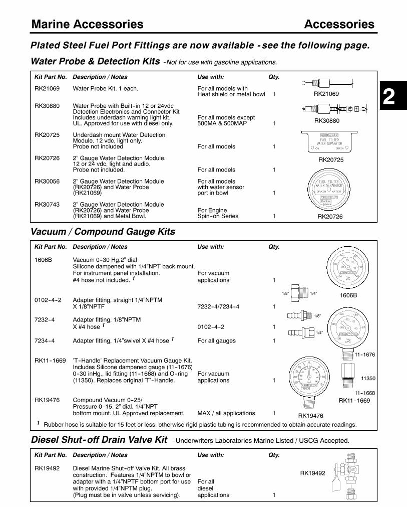
149
Marine Accessories
Kit Part No. Description / Notes Use with: Qty.
RK21069 Water Probe Kit, 1 each. For all models withHeat shield or metal bowl 1
RK30880 Water Probe with Built--in 12 or 24vdcDetection Electronics and Connector KitIncludes underdash warning light kit. For all models exceptUL. Approved for use with diesel only. 500MA & 500MAP 1
RK20725 Underdash mount Water DetectionModule. 12 vdc, light only.Probe not included For all models 1
RK20726 2” Gauge Water Detection Module.12 or 24 vdc, light and audio.Probe not included. For all models 1
RK30056 2” Gauge Water Detection Module For all models(RK20726) and Water Probe with water sensor(RK21069) port in bowl 1
RK30743 2” Gauge Water Detection Module(RK20726) and Water Probe For Engine(RK21069) and Metal Bowl. Spin--on Series 1
Plated Steel Fuel Port Fittings are now available - see the following page.
RK20725
Vacuum / Compound Gauge KitsKit Part No. Description / Notes Use with: Qty.
1606B Vacuum 0--30 Hg.2” dialSilicone dampened with 1/4”NPT back mount.For instrument panel installation. For vacuum#4 hose not included. 1 applications 1
0102--4--2 Adapter fitting, straight 1/4”NPTMX 1/8”NPTF 7232--4/7234--4 1
7232--4 Adapter fitting, 1/8”NPTMX #4 hose 1 0102--4--2 1
7234--4 Adapter fitting, 1/4”swivel X #4 hose 1 For all gauges 1
RK11--1669 ’T--Handle’ Replacement Vacuum Gauge Kit.Includes Silicone dampened gauge (11--1676)0--30 inHg., lid fitting (11--1668) and O--ring For vacuum(11350). Replaces original ’T’--Handle. applications 1
RK19476 Compound Vacuum 0--25/Pressure 0--15. 2” dial. 1/4”NPTbottom mount. UL Approved replacement. MAX / all applications 1
Accessories
RK20726
1606B
RK19476
11--1676
11--1668
11350
RK11--1669
1 Rubber hose is suitable for 15 feet or less, otherwise rigid plastic tubing is recommended to obtain accurate readings.
Diesel Shut-off Drain Valve Kit --Underwriters Laboratories Marine Listed / USCG Accepted.
Kit Part No. Description / Notes Use with: Qty.
RK19492 Diesel Marine Shut--off Valve Kit. All brassconstruction. Features 1/4”NPTM to bowl oradapter with a 1/4”NPTF bottom port for use For allwith provided 1/4”NPTM plug. diesel(Plug must be in valve unless servicing). applications 1
RK19492
2RK30880
RK21069
1/8” 1/4”
1/4”
1/8”
Water Probe & Detection Kits --Not for use with gasoline applications.
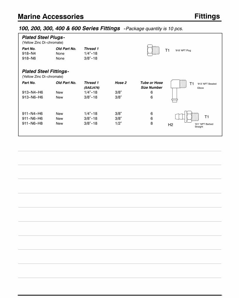
150
Marine Accessories Fittings
100, 200, 300, 400 & 600 Series Fittings --Package quantity is 10 pcs.
Plated Steel Plugs-(Yellow Zinc Di--chromate)
Part No. Old Part No. Thread 1918--N4 None 1/4”--18918--N6 None 3/8”--18
Plated Steel Fittings-(Yellow Zinc Di--chromate)
Part No. Old Part No. Thread 1 Hose 2 Tube or Hose(SAEJ476) Size Number
913--N4--H6 New 1/4”--18 3/8” 6913--N6--H6 New 3/8”--18 3/8” 6
911--N4--H6 New 1/4”--18 3/8” 6911--N6--H6 New 3/8”--18 3/8” 6911--N6--H8 New 3/8”--18 1/2” 8
T1
H2
T1 ’913’ NPT Beaded
Elbow
’911’ NPT BarbedStraight
T1 ’918’ NPT Plug

Racor Products Section 3 Recycling & High Flow
Global FiltrationTechnology
Help & General Information
?
Selection
Introduction
800D-5REC
8250D
812
75812
79812
850
800D-OF3
154
SELECTION -- SECTION 3
DIESEL FUEL FILTERING / RECYCLING / BLENDING:1. Find the location: Portable or Stationary Mount Models.
2. Find the installation.Will the unit be installed on the suction (vacuum) or pressure side of afuel pump? Racor units are most efficient when installed on the suction side of a fuel pump.TheRecycling systems are intended for suction installations however theModel 850may beusedfor pressure installations up to 150 PSI.
3. What other conditions apply?Water contamination is a problem. An in--unit water sensing detector should be added to informthe operator of a rapid build--up of water and necessary servicing. These are available for mostunits. Some models have automatic water draining features. Use with Diesel applications, only.
Is the unit intended to service a fleet of vehicles? The portable 800D--5REC is recommended forfleet use.
With the above information, review the models suggested that best fit your installation.Most of the Model Groups have addition information to help in identifying the exactmodelfor your needs.
Call your Racor distributor or Racor Customer Service if you need additional assistance at(209) 521--7860 or (800) 344--3286, 6:00 AM to 5:00 PM, Pacific Time.
FUEL FILTERING / OIL BLENDING SYSTEMS:1. Go directly to the Fuel Filtering / Blending units for specific selection information.
HYDRAULIC FILTERING SYSTEMS:1. Go directly to the Hydraulic Filtering System Section for specific selection information.
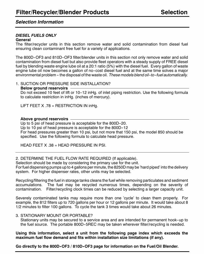
156
Filter/Recycler/Blender Products
Selection Information
DIESEL FUELS ONLYGeneralThe filter/recycler units in this section remove water and solid contamination from diesel fuelensuring clean contaminant free fuel for a variety of applications.
The 800D--OF3 and 810D--OF3 filter/blender units in this section not only remove water and solidcontamination from diesel fuel but also provide fleet operators with a steady supply of FREE dieselfuel by blending waste engine lube oil at a 20:1 ratio (5%) with the diesel fuel. Every gallon of wasteengine lube oil now becomes a gallon of no--cost diesel fuel and at the same time solves a majorenvironmental problem -- the disposal of thewasteoil. Thesemodelsblend oil--to--fuel automatically.
1. SUCTION OR PRESSURE SIDE INSTALLATION?Below ground reservoirsDo not exceed 10 feet of lift or 10--12 inHg. of inlet piping restriction. Use the following formulato calculate restriction in inHg. (inches of mercury).
LIFT FEET X .78 = RESTRICTION IN inHg.
Above ground reservoirsUp to 5 psi of head pressure is acceptable for the 800D--20.Up to 10 psi of head pressure is acceptable for the 800D--12For head pressures greater than 10 psi, but not more that 150 psi, the model 850 should bespecified. Use the following formula to calculate head pressure.
HEAD FEET X .38 = HEAD PRESSURE IN PSI.
2. DETERMINE THE FUEL FLOW RATE REQUIRED (If applicable).Selection should be made by considering the primary use for the unit.For fuel dispensing pumpsup to 4 gallons perminute, the 8250Dmaybe ’hard piped’ into the deliverysystem. For higher dispenser rates, other units may be selected.
Recycling/filtering the fuel in storage tanks cleans the fuel while removing particulates and sedimentaccumulations. The fuel may be recycled numerous times, depending on the severity ofcontamination. Filter/recycling clock times can be reduced by selecting a larger capacity unit.
Severely contaminated tanks may require more than one ’cycle’ to clean them properly. Forexample, the 812 filters up to 720 gallons per hour or 12 gallons per minute. It would take about 81/2 minutes to filter 100 gallons. To cycle the tank 3 times would take about 26 minutes.
3. STATIONARY MOUNT OR PORTABLE?Stationary units may be secured to a service area and are intended for permanent hook--up tothe fuel source. The portable 800D--5REC may be taken wherever filter/recycling is needed.
Using this information, select a unit from the following page index which exceeds themaximum fuel flow demand and fits within installation size limitations (if any).
Go directly to the 800D--OF3 / 810D--OF3 page for information on the Fuel/Oil Blender.
Selection
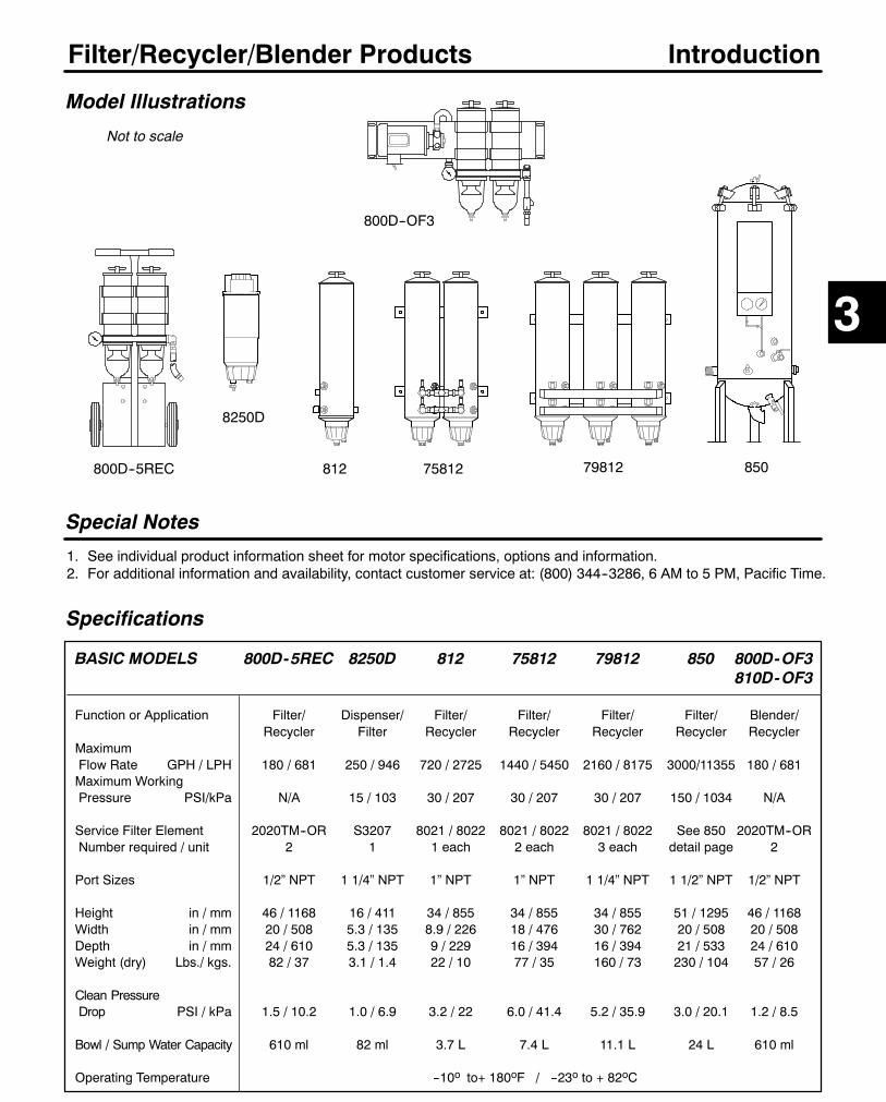
157
Filter/Recycler/Blender Products
Specifications
BASIC MODELS 800D-5REC 8250D 812 75812 79812 850 800D-OF3810D-OF3
Function or Application Filter/ Dispenser/ Filter/ Filter/ Filter/ Filter/ Blender/Recycler Filter Recycler Recycler Recycler Recycler Recycler
MaximumFlow Rate GPH / LPH 180 / 681 250 / 946 720 / 2725 1440 / 5450 2160 / 8175 3000/11355 180 / 681Maximum WorkingPressure PSI/kPa N/A 15 / 103 30 / 207 30 / 207 30 / 207 150 / 1034 N/A
Service Filter Element 2020TM--OR S3207 8021 / 8022 8021 / 8022 8021 / 8022 See 850 2020TM--ORNumber required / unit 2 1 1 each 2 each 3 each detail page 2
Port Sizes 1/2” NPT 1 1/4” NPT 1” NPT 1” NPT 1 1/4” NPT 1 1/2” NPT 1/2” NPT
Height in / mm 46 / 1168 16 / 411 34 / 855 34 / 855 34 / 855 51 / 1295 46 / 1168Width in / mm 20 / 508 5.3 / 135 8.9 / 226 18 / 476 30 / 762 20 / 508 20 / 508Depth in / mm 24 / 610 5.3 / 135 9 / 229 16 / 394 16 / 394 21 / 533 24 / 610Weight (dry) Lbs./ kgs. 82 / 37 3.1 / 1.4 22 / 10 77 / 35 160 / 73 230 / 104 57 / 26
Clean PressureDrop PSI / kPa 1.5 / 10.2 1.0 / 6.9 3.2 / 22 6.0 / 41.4 5.2 / 35.9 3.0 / 20.1 1.2 / 8.5
Bowl / Sump Water Capacity 610 ml 82 ml 3.7 L 7.4 L 11.1 L 24 L 610 ml
Operating Temperature --10o to+ 180oF / --23o to + 82oC
Model Illustrations
Special Notes
1. See individual product information sheet for motor specifications, options and information.2. For additional information and availability, contact customer service at: (800) 344--3286, 6 AM to 5 PM, Pacific Time.
Introduction
800D--5REC
3
850
8250D
800D--OF3
Not to scale
812 75812 79812
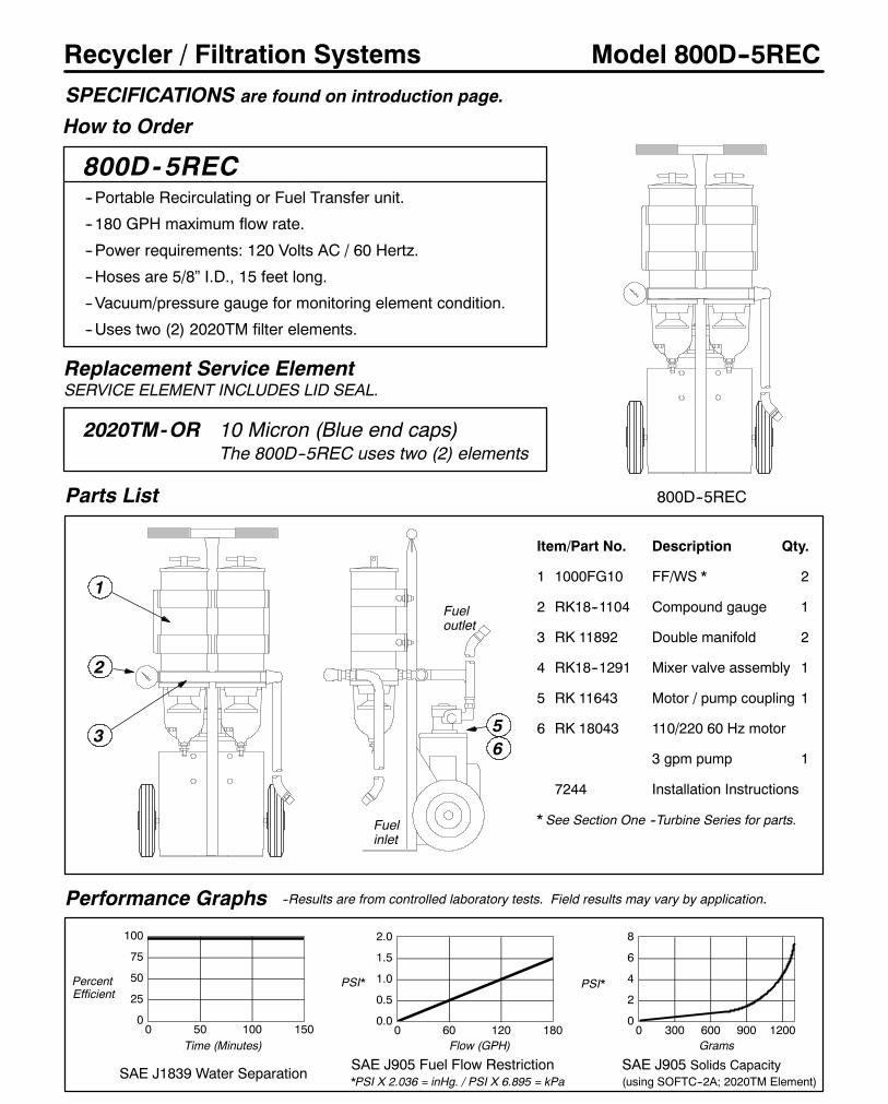
158
Recycler / Filtration Systems
How to Order
Model 800D--5REC
800D- 5REC--Portable Recirculating or Fuel Transfer unit.
-- 180 GPH maximum flow rate.
--Power requirements: 120 Volts AC / 60 Hertz.
--Hoses are 5/8” I.D., 15 feet long.
--Vacuum/pressure gauge for monitoring element condition.
--Uses two (2) 2020TM filter elements.
Performance Graphs
0
25
50
75
100
0 50 100 150
SAE J1839 Water Separation
PercentEfficient
Time (Minutes)
Parts List
Replacement Service ElementSERVICE ELEMENT INCLUDES LID SEAL.
2020TM-OR 10 Micron (Blue end caps)The 800D--5REC uses two (2) elements
0.0
0.5
1.0
1.5
2.0
0 60 120 180
SAE J905 Fuel Flow Restriction*PSI X 2.036 = inHg. / PSI X 6.895 = kPa
Flow (GPH)
PSI*
0
2
4
6
8
0 300 600 900 1200
SAE J905 Solids Capacity(using SOFTC--2A; 2020TM Element)
Grams
PSI*
--Results are from controlled laboratory tests. Field results may vary by application.
SPECIFICATIONS are found on introduction page.
800D--5REC
3
2
Item/Part No. Description Qty.
1 1000FG10 FF/WS * 2
2 RK18--1104 Compound gauge 1
3 RK 11892 Double manifold 2
4 RK18--1291 Mixer valve assembly 1
5 RK 11643 Motor / pump coupling 1
6 RK 18043 110/220 60 Hz motor
3 gpm pump 1
7244 Installation Instructions
* See Section One --Turbine Series for parts.
56
1
Fuelinlet
Fueloutlet
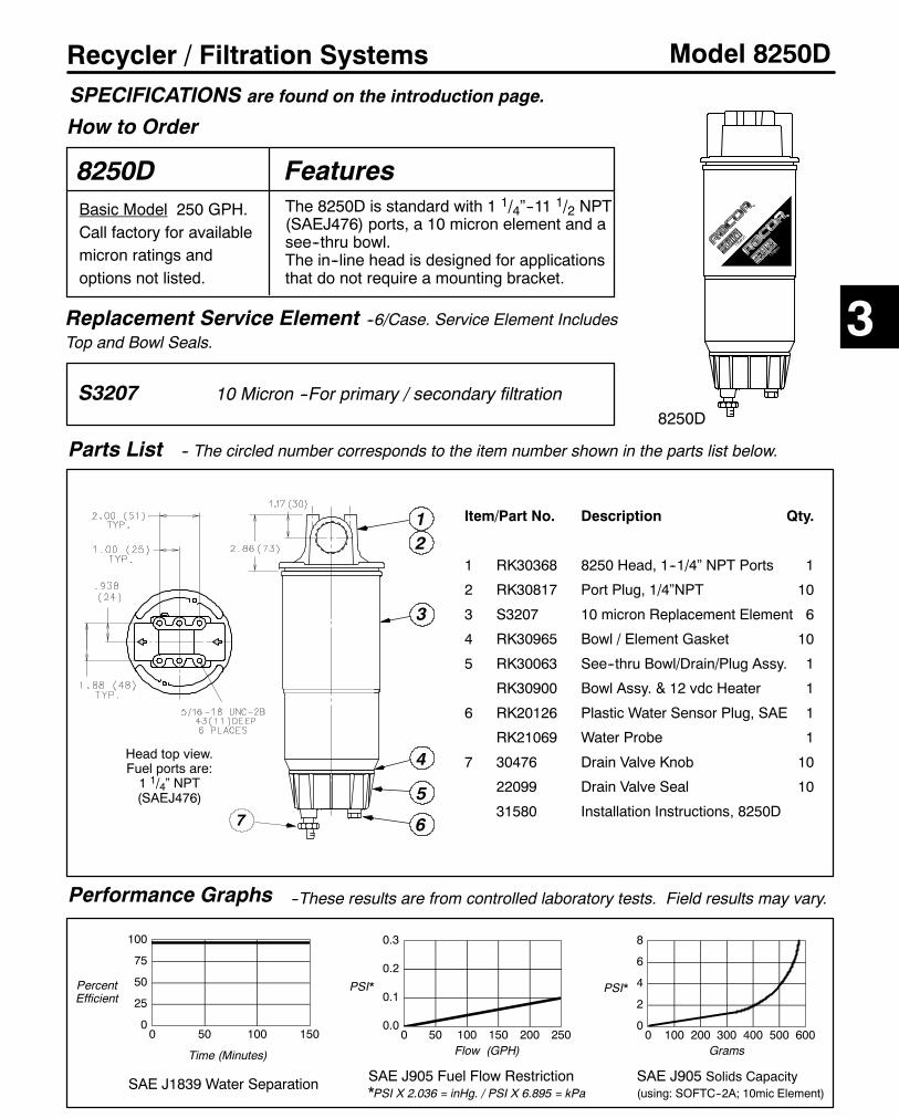
159
Recycler / Filtration Systems Model 8250D
8250D
Performance Graphs
0
25
50
75
100
0 50 100 150
SAE J1839 Water Separation
PercentEfficient
Time (Minutes)
Replacement Service Element --6/Case. Service Element IncludesTop and Bowl Seals.
S3207 10 Micron --For primary / secondary filtration
0.0
0.1
0.2
0.3
0 50 100 150 200 250
SAE J905 Fuel Flow Restriction*PSI X 2.036 = inHg. / PSI X 6.895 = kPa
Flow (GPH)
PSI*
0
2
4
6
8
0 100 200 300 400 500 600
SAE J905 Solids Capacity(using: SOFTC--2A; 10mic Element)
Grams
PSI*
--These results are from controlled laboratory tests. Field results may vary.
8250D
Parts List
1
3
67
4
5
Basic Model 250 GPH.Call factory for availablemicron ratings andoptions not listed.
Head top view.Fuel ports are:1 1/4” NPT(SAEJ476)
-- The circled number corresponds to the item number shown in the parts list below.
The 8250D is standard with 1 1/4”--11 1/2 NPT(SAEJ476) ports, a 10 micron element and asee--thru bowl.The in--line head is designed for applicationsthat do not require a mounting bracket.
Features
Item/Part No. Description Qty.
1 RK30368 8250 Head, 1--1/4” NPT Ports 1
2 RK30817 Port Plug, 1/4”NPT 10
3 S3207 10 micron Replacement Element 6
4 RK30965 Bowl / Element Gasket 10
5 RK30063 See--thru Bowl/Drain/Plug Assy. 1
RK30900 Bowl Assy. & 12 vdc Heater 1
6 RK20126 Plastic Water Sensor Plug, SAE 1
RK21069 Water Probe 1
7 30476 Drain Valve Knob 10
22099 Drain Valve Seal 10
31580 Installation Instructions, 8250D
2
How to Order
SPECIFICATIONS are found on the introduction page.
3

160
Recycler / Filtration Systems Model 812
812BasicModel 720GPH / 2725LPHStationary Fuel Filter / WaterSeparator that uses two standardRacor replacement elements.Installation is on the suction sideof the pump for maximumefficiency and filter life.
Performance Graphs
0
25
50
75
100
0 50 100 150
SAE J1839 Water Separation
PercentEfficient
Time (Minutes)
Parts List
012345
0 144 288 432 576 720
SAE J905 Fuel Flow Restriction* PSI X 2.036 = inHg. / PSI X 6.895 =kPa
Flow (GPH)
PSI*
0
2
4
6
8
0 150 300 450 600 750 900
SAE J905 Solids Capacity(using SOFTC--2A & above elements)
Grams
PSI*
--Results are from controlled laboratory tests. Field results may vary by application.
SPECIFICATIONS are found on System introduction page.
Features-- Inlet/outlet ports: 1” -- 11 1/2 NPTF--Rugged steel housingwith twomountingbrackets, with protective epoxy coating.
--Removeable steel lid with T--handle foreasy element access and fuel priming.
--See--thru collection bowl allows quickvisual inspection.
Item/Part No. Description Qty.
1 RK22682 T--Handle/Lid Assembly 12 RK22609 Lid Gasket 13 RK22610 Element Kit. (1)8021,
(1)8022 and Includes LidGasket 1
4 RK11036 Bowl O--Ring 15 RK16017--01 Bowl Assembly 16 RK30058 Drain Valve Assembly 1
RK21069* Water Probe (Option) 1RK30880 Electronic Water Probe
(Option) 122586 812 Installation Instructions
*Must be used with a Water Detection Module.For parts not shown, call Racor customer service: (800)
344--3286, 6 AM to 5 PM, Pacific Time.
1
2
3
56
4
TOP VIEW
Replacement Service Elements --Order one (1) kit per unit.SERVICE ELEMENT KIT INCLUDES LID SEAL.
RK22610 Element Kit. Includes (1) 40 Micron Filter (upperposition) and (1) Coalescing Filter (lower position)
Overhead clearance requiredfor element removal: 12” / 305mm.
(Not to scale)
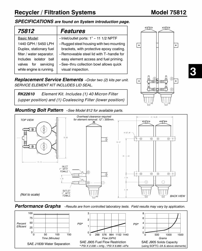
161
Recycler / Filtration Systems Model 75812
75812Basic Model:1440 GPH / 5450 LPHDuplex, stationary fuelfilter / water separator.Includes isolator ballvalves for servicingwhile engine is running.
Performance Graphs
0
25
50
75
100
0 50 100 150
SAE J1839 Water Separation
PercentEfficient
Time (Minutes)
Mounting Bolt Pattern --See Model 812 for available parts.
Replacement Service Elements --Order two (2) kits per unit.SERVICE ELEMENT KIT INCLUDES LID SEAL.
RK22610 Element Kit. Includes (1) 40 Micron Filter(upper position) and (1) Coalescing Filter (lower position)
0
1
2
3
0 288 576 864 1152 1440
SAE J905 Fuel Flow Restriction* PSI X 2.036 = inHg. / PSI X 6.895 =kPa
Flow (GPH)
PSI*
0
2
4
6
8
0 500 1000 1500
SAE J905 Solids Capacity(using SOFTC--2A & above elements)
Grams
PSI*
--Results are from controlled laboratory tests. Field results may vary by application.
SPECIFICATIONS are found on System introduction page.
Features-- Inlet/outlet ports: 1” -- 11 1/2 NPTF--Rugged steel housingwith twomountingbrackets, with protective epoxy coating.
--Removeable steel lid with T--handle foreasy element access and fuel priming.
--See--thru collection bowl allows quickvisual inspection. 3
TOP VIEW
BACK VIEW(Not to scale)
Overhead clearance requiredfor element removal: 12” / 305mm.
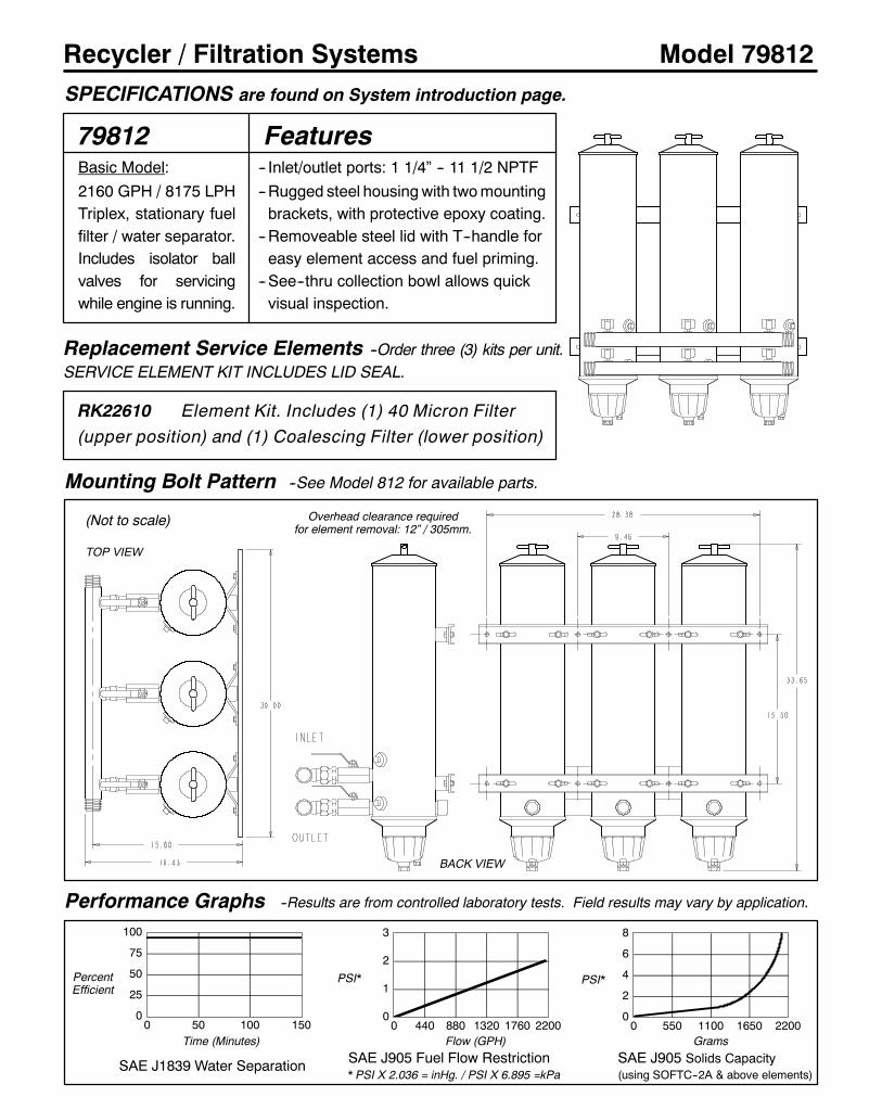
162
Recycler / Filtration Systems Model 79812
79812Basic Model:2160 GPH / 8175 LPHTriplex, stationary fuelfilter / water separator.Includes isolator ballvalves for servicingwhile engine is running.
Performance Graphs
0
25
50
75
100
0 50 100 150
SAE J1839 Water Separation
PercentEfficient
Time (Minutes)
Mounting Bolt Pattern --See Model 812 for available parts.
Replacement Service Elements --Order three (3) kits per unit.SERVICE ELEMENT KIT INCLUDES LID SEAL.
RK22610 Element Kit. Includes (1) 40 Micron Filter(upper position) and (1) Coalescing Filter (lower position)
0
1
2
3
0 440 880 1320 1760 2200
SAE J905 Fuel Flow Restriction* PSI X 2.036 = inHg. / PSI X 6.895 =kPa
Flow (GPH)
PSI*
0
2
4
6
8
0 550 1100 1650 2200
SAE J905 Solids Capacity(using SOFTC--2A & above elements)
Grams
PSI*
--Results are from controlled laboratory tests. Field results may vary by application.
SPECIFICATIONS are found on System introduction page.
Features-- Inlet/outlet ports: 1 1/4” -- 11 1/2 NPTF--Rugged steel housingwith twomountingbrackets, with protective epoxy coating.
--Removeable steel lid with T--handle foreasy element access and fuel priming.
--See--thru collection bowl allows quickvisual inspection.
TOP VIEW
BACK VIEW
(Not to scale) Overhead clearance requiredfor element removal: 12” / 305mm.

163
Recycler / Filtration Systems
How to Order --The example below illustrates how the part numbers are constructed.
Model 850
850Basic Model
3000 GPH
Constructed to
A S M E
guidelines.
Water sight ports
and two manual
drain valves are
standard.
Performance Graphs
0
25
50
75
100
0 50 100 150
SAE J1839 Water Separation
PPMfreewaterEfficient
Time (Minutes)
Mounting Hole Pattern / Parts List
Replacement Service Elements
The 850 typically uses 7 ’8021’ 40 micron filtration elements (upper) and 7 ’8022’ coalescing elements (lower).
RK8023S/CM Includes (7) 8021 40 micron elements and (7) 8022 Coalescing elements.RK18-1669 Includes (14) 8021 40 micron elements.RK18-1683 Includes (7) 8022 Coalescing elements and (7) dual--stage 10/40 micron elements.
0
1
2
3
4
0 600 1200 1800 2400 3000
SAE J905 Fuel Flow Restriction* PSI X 2.036 = inHg. / PSI X 6.895 = kPa
Flow (GPH)
PSI*
0
2
4
6
8
0 500 1000 1500
SAE J905 Solids Capacity(using SOFTC--2A) @ 10 microns
Grams
PSI*
--Results are from controlled laboratory tests. Field results may vary by application.
SPECIFICATIONS are found on System introduction page.
WSOptions’MD’ Basic model with manual drains
’WS’ Manual Drain and Water Probe
’H’ Manual Drain and 1000 watt Heater
’WSH’ Manual Drain, Water Probe and Heater
’SG’ Manual Drain and Switch/gauge
’SGWS’ Manual Drain, Water Probe and Switch/gauge
’SGWSH’ Manual Drain, Water Probe, Heater and Switch/gauge
’AD’ 110 VAC Automatic Drain, Water Probe and Switch/gauge
Item/Part No. Description Qty.
1 RK18--1441 O--Ring, 14” diameter 1
2 18--1369 Pressure Relief Valve 1
3 RK20726 Water Detector Gauge 1
4 RK18--1422 Pressure Gauge 1
5 RK18--1371 Sight Plug 1
6 RK18--1454 Water Probe 1
18--1392 Installation Instructions
For parts not listed, call Racor customer service:
(800) 344--3286, 6 AM to 5 PM, Pacific Time.
1
34
65
--Service elements DO NOT include the tank O--ring. See parts list.
23” (584 mm) overhead clearancerequired for element removal.
2(Backside)
Top View
Outlet:1 1/2”NPT
Inlet:1 1/2”NPT
17.13” (435 mm) 5/8” fastener boltcircle. Three spaced 120o apart.
Bolt Pattern
(Not to scale)
3

164
Blender / Filtration Systems
How to Order --The example below illustrates how the part numbers are constructed.
Model 800D--OF3
800D-OF3 D
Performance Graphs
0
25
50
75
100
0 50 100 150
SAE J1839 Water Separation
PercentEfficient
Time (Minutes)
3/8” (10 mm) diameterclearance for fasteners.
11.75”(298 mm)
Mounting Hole Pattern / Parts List
Replacement Service ElementsSERVICE ELEMENTS INCLUDE LID SEALS.
2020TM-OR 10 Micron (Blue end caps)These models use two (2) elements
0.0
0.5
1.0
1.5
2.0
0 60 120 180
SAE J905 Fuel Flow Restriction*PSI X 2.036 = inHg. / PSI X 6.895 =kPa
Flow (GPH)
PSI*
0
2
4
6
8
0 300 600 900 1200
SAE J905 Solids Capacity(using SOFTC--2A; 2020TM Element)
Grams
PSI*
--Results are from controlled laboratory tests. Field results may vary by application.
SPECIFICATIONS are found on Introduction page.
800--OF3(VAC Motor)
19.75”(502 mm)
Outlet1/2”NPT
5.75”(146 mm)
810--OF3(VDC Motor)
Item/Part No. Description Qty.4 RK18--1291 Mixer valve assembly 15 1000FG10 FF/WS * 26 RK11892 Double manifold 27 RK18--1104 Compound gauge 1
7245 Installation Instructions* See Section One --Turbine Series for parts listing.
7
1 2
5
3
4
Item/Part No. Description Qty.1 RK11643 Motor / pump coupling 12 RK18043 110/220 60 Hz motor/3 gpm pump 1
RK18544 110/220 50 Hz motor/3 gpm pump 1RK18--1144 12 VDC motor/3 gpm pump 1RK18--1145 24 VDC motor/3 gpm pump 1
3 RK18999 Main mounting bracket 1
6Oil inlet
Fuelinlet
Recycler/Blenders: 180 GPH
800D--OF3: VAC Model.
Specify one voltage from D to G.
810D--OF3: VDC Model.
Specify one voltage: A or B.
Motor Voltage: Specify one.’A’ 12 VDC’B’ 24 VDC’D’ 100 VAC / 60 Hz’E’ 110 VAC / 50 Hz’F’ 220 VAC / 60 Hz’G’ 220 VAC / 50 Hz
(Not to scale)

Racor Products Section 4 Interceptor Products
Global FiltrationTechnology
Help & General Information
?
Interceptor Filer Products
OEM Replacement Filters
Fuel Dispensing Filters And Heads
Alpha-numerical Parts List

178
Interceptor Filter Products Navistar 6.9L Filter /Filter Applications
Navistar 6.9l Replacement Fuel FiltersThe Interceptor Direct Replacement Fuel Filter for the Navistar 6.9L diesel engine upgrades the standard fuel filter toa spin--on fuel filter and water separator with a metal bowl. At filter change time, only the spin--on can is replaced: thebowl spins off and is reusable. Interceptor Filter Products meet OEM specifications.
Part Number Description Qty./Case
IN BF811 Replaces standard fuel filter on 6.9L diesel in Ford E & F Series vehicles 12IN F811 Replacement Fuel Filter for above. 12
IN RK30785 Water Sensor Kit for IN BF811 applications. Replaces the OEM water sensor. 1
Navistar 6.9l Complete Replacement AssembliesThe Interceptor 6.9L Diesel Replacement Kits for Ford E & F Series vehicles are designed to upgrade the fuel filtersystem quickly and easily. The kit includes a fuel filter/water separator with an in--filter fuel heater and a water sensorprobe that fits existing circuitry. A more reliable, higher quality, exact fit replacement is guaranteed!
Part Number Description Qty./Case
IN RK30787 Navistar 6.9L Replacement Kit for Ford F Series trucks (uses IN F829B filter). 1IN RK30801 Navistar 6.9L Replacement Kit for Ford E Series vans (uses IN F829B filter). 1
IN RK20567 Replacement Metal Bowl Kit for IN F811, IN F829B, IN F830 and IN F831 1IN RK21057 Replacement Clear Bowl Kit for IN F811, IN F829B, IN F830 and IN F831 1
Replacement Filters For OEM ApplicationsInterceptor Filter Products offers patented replacement filter elements for specific OEM applications and engines.
Part Number Description Qty./Case
IN F829B Navistar 7.3L diesel in Ford E & F Series vehicles, 2 micron. 12IN F830 Navistar 7.3L medium--duty trucks and buses, 40 micron. 12IN F831 Navistar 6400 Series fuel heater/filter/water separators, 40 micron. 6IN F4595 Navistar T444E (7.3L) Powerstroke (model years 1994 to 1999) 12IN F4596 Navistar T444E (7.3L) Powerstroke (model year 1999 to current) 12IN F4597 Ford 550 and 650 with Cat engines and cold weather element 12IN F264 Bosch, Iveco, Deutz, MAN & Volvo fuel filter replacement (center thread: 16M). 12IN F19528 Dodge trucks with Cummins engine, replacement element (model yrs. 1998 & 1999) 12
IN F296 CAV: Replaces CAV7111/296. 24IN F796 CAV: Replaces CAV7111/796. 24
IN F3368 Ford 6.6L/7.8L engines, 1991 -- 1992. 12IN FR26P Ford 6.6L/7.8L engines, 1985 -- 1990. 12
IN F18786 Replaces Stanadyne Fuel Filter No.18667 (square, box--type) 12IN F19797 Replaces Stanadyne Fuel/Water Separator No.19856 (square, box--type) 12
IN F52525 Replaces Webb #52525 / DDC Applications 12
Replacement Filters for DahlPart Number Model / Micron Qty./ Part Number Model / Micron Qty./
IN 101--2 100, 2 micron 18 IN 201--10 200, 10 micron 18IN 101--10 100, 10 micron 18 IN 201--30 200, 30 micron 18IN 101--30 100, 30 micron 18 IN 301--10 300, 10 micron 18IN 201--2 200, 2 micron 18 IN 301--30 300, 30 micron 18

180
Interceptor Filter Products Fuel Dispensing FiltersFuel Dispensing Filters And Filter HeadsInterceptor fuel dispensing filters start protecting engines at the source, removing virtually100% of contaminants from diesel or gasoline, including water, dirt, dust, rust and biologicalmicroorganisms. By trapping this contamination, precision fuel system components areprotected from abrasion and wear. These units are essential for stationary pumps, overheadtanks, marinas and mobile service vehicles.Interceptor fuel dispensing filters offer protection down to 10microns. Flow rates range from15 to 100 GPM. Filter servicing is clean and easy with just a spin.
Interceptor filters feature a super--absorbant, chemically--treated media with two unique features:1. The filter media absorbs 25 times its weight in water and locks it in. It is an effective barrieragainst free and emulsified water.
2. As the media swells with water removed from the fuel, it gradually reduces the flow rate,signaling the need to replace the filter. The absence of a bypass valve insures that fuelsystem will be completely protected.
Interceptor filters are engineered and manufactured under the most up--to--date qualitycontrol processes to meet or exceed original equipment specifications.
Water Absorbing FiltersMaximum operating pressure: 100 PSI / 689.6 kPa1IN FDC filters have a cellulose media and do NOT absorb water. 2Filters with the ’A’ media hold more dirt andwater than standard water absorbing media. More frequent element changes may be necessary.
Filter HeadsMaximum operating pressure: 100 PSI / 689.6 kPa1Head/element seal available: IN GCSG100, packaged 5/kit. 2Dual filter unit. Order two filters when using this model.
INTERCEPTOR
CAV Filter Adapter KitFilter Adapter Kit IN CAV turns old C.A.V. Filter Head, cannister and glass bowl unitsinto a spin--on filter. Fits Ford, Perkins, Massey Ferguson, Saab, Volvo--Penta andmore! This kit allows the use of Interceptor Spin--On Filters that feature the patentedsee--thru, spin--on contaminant collection bowl: IN B32008 or IN B32016. Forengines up to 70 HP.
Part Number Description Applications Qty./Case
IN CAV Adapter Kit Ford, Perkins, Massey,Saab, Volvo--Penta,
Ford Lehman 1
C.A.V. FilterHead
IN CAVAdapter
InterceptorIN B32008 orIN B32016FilterAssembly
IN HH07500
IN FDH125001
IN FDH125DD1,2
1”--12
1 1/2”--16
1 1/4” NPT
3/4“ NPT
1 1/2” NPT
50
100
15 No Bypass 1
1
PartNumber
CenterThread
PortSizes
Fuel FlowRate (GPM)
FilterApplication
BypassSetting
RestrictionGauge
CaseQty.
FDW51125
FDW51125 (2)
1
Optional
1 1/2”--16
FDW3525/FDW3825
GaugePort
No Bypass
No Bypass
Optional
Optional
1/8” NPT
1/8” NPT
1/8” NPT
MicronRating
CenterThread
FilterDiameter
PartNumber
CaseQty.
FilterLength
SolidsCapacity (g)
WaterCapacity (ml)
Typical BetaRating (uM)
IN FDC3510G1
IN FDW3830
1 1/2”--16
3.75 in.
11.0 in.
5.0 in.
IN FDC3530G1
IN FDW3510
IN FDW3510A2
IN FDW3525
IN FDW3810A2
IN FDW3825
10
10
30
10
25
25
25
1”--12
1”--12
1 1/2”--16
3.75 in.
3.75 in.
3.75 in.
5.0 in.
5.0 in.
8.0 in.
8.0 in.
15.58
28.71
247
247
455
10/18
IN FDW51125
10
30
1”--12 3.75 in.
190 / 1226
190 / 1226
350 / 2258
689 / 4444
13.68
56.50 896
14/23
14/23
14/23
1 1/2”--16
1”--12
1”--12
1”--12
3.75 in.
3.75 in.
3.75 in.
5.0 in.
5.0 in.
5.0 in.
5.0 in.
6
12
12
12
Media Area(Sq in. /Sq cm)
N/A
N/A
12
12
12
12
12480 / 3096 9.04 10/18
480 / 3096 9.04 10/18
335 / 2161 13.68 175 10/18
608 / 3923 39.48 315 10/18
350 / 2258 28.71 455 14/23
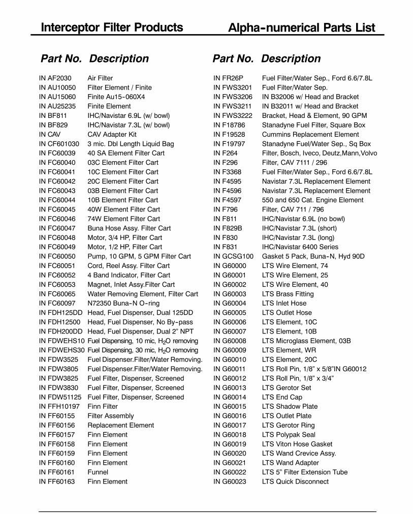
Interceptor Filter Products Alpha--numerical Parts List
185
Part No. Description Part No. Description
IN AF2030 Air FilterIN AU10050 Filter Element / FiniteIN AU15060 Finite Au15--060X4IN AU25235 Finite ElementIN BF811 IHC/Navistar 6.9L (w/ bowl)IN BF829 IHC/Navistar 7.3L (w/ bowl)IN CAV CAV Adapter KitIN CF601030 3 mic. Dbl Length Liquid BagIN FC60039 40 SA Element Filter CartIN FC60040 03C Element Filter CartIN FC60041 10C Element Filter CartIN FC60042 20C Element Filter CartIN FC60043 03B Element Filter CartIN FC60044 10B Element Filter CartIN FC60045 40W Element Filter CartIN FC60046 74W Element Filter CartIN FC60047 Buna Hose Assy. Filter CartIN FC60048 Motor, 3/4 HP, Filter CartIN FC60049 Motor, 1/2 HP, Filter CartIN FC60050 Pump, 10 GPM, 5 GPM Filter CartIN FC60051 Cord, Reel Assy. Filter CartIN FC60052 4 Band Indicator, Filter CartIN FC60053 Magnet, Inlet Assy.Filter CartIN FC60065 Water Removing Element, Filter CartIN FC60097 N72350 Buna--N O--ringIN FDH125DD Head, Fuel Dispenser, Dual 125DDIN FDH12500 Head, Fuel Dispenser, No By--passIN FDH200DD Head, Fuel Dispenser, Dual 2” NPTIN FDWEHS10 Fuel Dispensing, 10 mic, H2O removingIN FDWEHS30 Fuel Dispensing, 30 mic, H2O removingIN FDW3525 Fuel Dispenser.Filter/Water Removing.IN FDW3805 Fuel Dispenser.Filter/Water Removing.IN FDW3825 Fuel Filter, Dispenser, ScreenedIN FDW3830 Fuel Filter, Dispenser, ScreenedIN FDW51125 Fuel Filter, Dispenser, ScreenedIN FFH10197 Finn FilterIN FF60155 Filter AssemblyIN FF60156 Replacement ElementIN FF60157 Finn ElementIN FF60158 Finn ElementIN FF60159 Finn ElementIN FF60160 Finn ElementIN FF60161 FunnelIN FF60163 Finn Element
IN FR26P Fuel Filter/Water Sep., Ford 6.6/7.8LIN FWS3201 Fuel Filter/Water Sep.IN FWS3206 IN B32006 w/ Head and BracketIN FWS3211 IN B32011 w/ Head and BracketIN FWS3222 Bracket, Head & Element, 90 GPMIN F18786 Stanadyne Fuel Filter, Square BoxIN F19528 Cummins Replacement ElementIN F19797 Stanadyne Fuel/Water Sep., Sq BoxIN F264 Filter, Bosch, Iveco, Deutz,Mann,VolvoIN F296 Filter, CAV 7111 / 296IN F3368 Fuel Filter/Water Sep., Ford 6.6/7.8LIN F4595 Navistar 7.3L Replacement ElementIN F4596 Navistar 7.3L Replacement ElementIN F4597 550 and 650 Cat. Engine ElementIN F796 Filter, CAV 711 / 796IN F811 IHC/Navistar 6.9L (no bowl)IN F829B IHC/Navistar 7.3L (short)IN F830 IHC/Navistar 7.3L (long)IN F831 IHC/Navistar 6400 SeriesIN GCSG100 Gasket 5 Pack, Buna--N, Hyd 90DIN G60000 LTS Wire Element, 74IN G60001 LTS Wire Element, 25IN G60002 LTS Wire Element, 40IN G60003 LTS Brass FittingIN G60004 LTS Inlet HoseIN G60005 LTS Outlet HoseIN G60006 LTS Element, 10CIN G60007 LTS Element, 10BIN G60008 LTS Microglass Element, 03BIN G60009 LTS Element, WRIN G60010 LTS Element, 20CIN G60011 LTS Roll Pin, 1/8” x 5/8”IN G60012IN G60012 LTS Roll Pin, 1/8” x 3/4”IN G60013 LTS Gerotor SetIN G60014 LTS End CapIN G60015 LTS Shadow PlateIN G60016 LTS Outlet PlateIN G60017 LTS Gerotor RingIN G60018 LTS Polypak SealIN G60019 LTS Viton Hose GasketIN G60020 LTS Wand Crevice Assy.IN G60021 LTS Wand AdapterIN G60022 LTS 5” Filter Extension TubeIN G60023 LTS Quick Disconnect
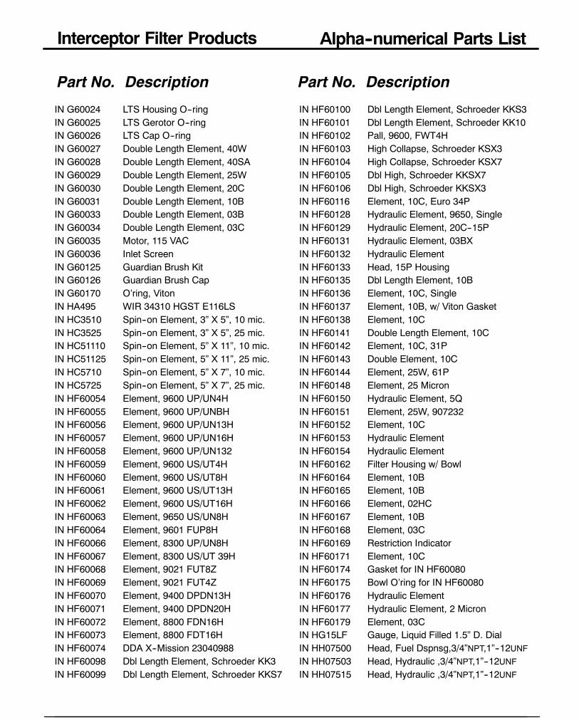
Interceptor Filter Products Alpha--numerical Parts List
186
Part No. Description Part No. Description
IN G60024 LTS Housing O--ringIN G60025 LTS Gerotor O--ringIN G60026 LTS Cap O--ringIN G60027 Double Length Element, 40WIN G60028 Double Length Element, 40SAIN G60029 Double Length Element, 25WIN G60030 Double Length Element, 20CIN G60031 Double Length Element, 10BIN G60033 Double Length Element, 03BIN G60034 Double Length Element, 03CIN G60035 Motor, 115 VACIN G60036 Inlet ScreenIN G60125 Guardian Brush KitIN G60126 Guardian Brush CapIN G60170 O’ring, VitonIN HA495 WIR 34310 HGST E116LSIN HC3510 Spin--on Element, 3” X 5”, 10 mic.IN HC3525 Spin--on Element, 3” X 5”, 25 mic.IN HC51110 Spin--on Element, 5” X 11”, 10 mic.IN HC51125 Spin--on Element, 5” X 11”, 25 mic.IN HC5710 Spin--on Element, 5” X 7”, 10 mic.IN HC5725 Spin--on Element, 5” X 7”, 25 mic.IN HF60054 Element, 9600 UP/UN4HIN HF60055 Element, 9600 UP/UNBHIN HF60056 Element, 9600 UP/UN13HIN HF60057 Element, 9600 UP/UN16HIN HF60058 Element, 9600 UP/UN132IN HF60059 Element, 9600 US/UT4HIN HF60060 Element, 9600 US/UT8HIN HF60061 Element, 9600 US/UT13HIN HF60062 Element, 9600 US/UT16HIN HF60063 Element, 9650 US/UN8HIN HF60064 Element, 9601 FUP8HIN HF60066 Element, 8300 UP/UN8HIN HF60067 Element, 8300 US/UT 39HIN HF60068 Element, 9021 FUT8ZIN HF60069 Element, 9021 FUT4ZIN HF60070 Element, 9400 DPDN13HIN HF60071 Element, 9400 DPDN20HIN HF60072 Element, 8800 FDN16HIN HF60073 Element, 8800 FDT16HIN HF60074 DDA X--Mission 23040988IN HF60098 Dbl Length Element, Schroeder KK3IN HF60099 Dbl Length Element, Schroeder KKS7
IN HF60100 Dbl Length Element, Schroeder KKS3IN HF60101 Dbl Length Element, Schroeder KK10IN HF60102 Pall, 9600, FWT4HIN HF60103 High Collapse, Schroeder KSX3IN HF60104 High Collapse, Schroeder KSX7IN HF60105 Dbl High, Schroeder KKSX7IN HF60106 Dbl High, Schroeder KKSX3IN HF60116 Element, 10C, Euro 34PIN HF60128 Hydraulic Element, 9650, SingleIN HF60129 Hydraulic Element, 20C--15PIN HF60131 Hydraulic Element, 03BXIN HF60132 Hydraulic ElementIN HF60133 Head, 15P HousingIN HF60135 Dbl Length Element, 10BIN HF60136 Element, 10C, SingleIN HF60137 Element, 10B, w/ Viton GasketIN HF60138 Element, 10CIN HF60141 Double Length Element, 10CIN HF60142 Element, 10C, 31PIN HF60143 Double Element, 10CIN HF60144 Element, 25W, 61PIN HF60148 Element, 25 MicronIN HF60150 Hydraulic Element, 5QIN HF60151 Element, 25W, 907232IN HF60152 Element, 10CIN HF60153 Hydraulic ElementIN HF60154 Hydraulic ElementIN HF60162 Filter Housing w/ BowlIN HF60164 Element, 10BIN HF60165 Element, 10BIN HF60166 Element, 02HCIN HF60167 Element, 10BIN HF60168 Element, 03CIN HF60169 Restriction IndicatorIN HF60171 Element, 10CIN HF60174 Gasket for IN HF60080IN HF60175 Bowl O’ring for IN HF60080IN HF60176 Hydraulic ElementIN HF60177 Hydraulic Element, 2 MicronIN HF60179 Element, 03CIN HG15LF Gauge, Liquid Filled 1.5” D. DialIN HH07500 Head, Fuel Dspnsg,3/4”NPT,1”--12UNFIN HH07503 Head, Hydraulic ,3/4”NPT,1”--12UNFIN HH07515 Head, Hydraulic ,3/4”NPT,1”--12UNF

Interceptor Filter Products Alpha--numerical Parts List
187
Part No. Description Part No. Description
IN HH07515MPHead, Multi--port,3/4”NPT,1”--12UNFIN HH07525 Head, Hyd.,3/4”NPT,25 PSI By--passIN HH07525MPHead, Multi--port,3/4”NPT,1”--12UNFIN HH12515L Head, 1 1/4”NPT, 1 1/2”--16UN/LIN HH12515MPHead, Multi--port,1 1/4”NPT, 1 1/2”--16UNIN HH12515R Head, 1 1/4”NPT, 1 1/2”--16UN--RIN HH12525L Head, 1 1/4”LEFT, 25 PSIIN HH12525MPHead, Multi--port,1 1/4”NPT, 1 1/2”--16UNIN HH12525R Head, 1 1/4”NPT, 1 1/2”--16UN/LIN HMG3606 Microglass element, 3” x 6” x 1 1/2”--16IN HM3504A Hydraulic Spin--on, 3 x 5 x 1, 1/2”--16IN HM5710 Hydraulic Element, 5 x 7, Micro GlassIN HN4L10CN Filter AssemblyIN HN92151 O’ringIN HP60077 Filter, Hydraulic Pressure, 20GPMIN HP60078 Element, 10C, 60077 HousingIN HP60079 Element, 10B, 60077 HousingIN HP60080 Filter, Hydraulic DBL, 20 GPMIN HP60081 Element, 10C, 60080 HousingIN HP60082 Double Element, 10B, 60080 HousingIN HP60083 Filter, Hydraulic Pressure, 50GPMIN HP60084 Element, 10C, 60083 HousingIN HP60085 Element, 10B, 60083 HousingIN HP60086 Filter, Hydraulic Pressure, DBL.50 GPMIN HP60087 Element, DBL. 10C, 60086 HousingIN HP60088 Double Element, 10B, 60086 HousingIN HP60089 Rotary IndicatorIN HP60090 Element, DBL. 03C, 60080 HousingIN HP60092 Element, 74W, S SeriesIN HP60093 Element, 20C, 2”IN HP60094 Element, 10Micron, K SeriesIN HP60095 Element, SNGL.03C, 60077 HousingIN HP60096 Element, 9600 FDT8HIN HP60107 High Collapse Element, 10BXIN HP60108 Element, 20C, 60083 HousingIN HP60109 High Collapse, 10B, 60086 HousingIN HP60115 Side Mount Rotary DialIN HP60119 High Collapse, 03B, 60083 HousingIN HP60121 Element, 40CN--2, 10C VitonIN HP60122 Element, 40CN--2, 10B VitonIN HP60123 Element, 50S, 10CIN HP60124 Element, 50P--1, 10BIN HP60139 Double Element, 10B, 2”IN HP60140 Buna Element, 10C
IN HP60145 Element, 03BIN HP60146 Filter HeadIN HP60147 Housing w/ High Collapse ElementIN HRBA11216 Breather Adapter, 1”--12, 1 1/2”--16IN HRBA3416 Breather Adapter, 3/4”--16, 1”--12IN HSSM511 Element, Stainless Steel Mesh,5” x 11”IN HSSM57 Element, Stainless Steel Mesh,5” x 7”IN HW33RB Reservoir Breather, 3”x3”, 10 micron,
water absorbing.IN HW35RB Reservoir Breather, 3”x5”, 10 mircon,
water absorbing.IN HW3510 Spin--on Hydraulic element, 3” X 5”, 10
micron, water absorbing, 1”--12 thread.IN HW3510A Same as above but w/ 1 1/8”--16 thrds.IN HW3525 Spin--on Hydraulic element, 3” X 5”, 25
micron, water absorbing.IN HW3810 Spin--on Hydraulic element, 3” X 8”, 10
micron, water absorbing.IN HW3825 Spin--on Hydraulic element, 3” X 8”, 25
micron, water absorbing.IN HW51110 Spin--onHydraulic element, 5” X 11”, 10
micron, water absorbing.IN HW51125 Spin--onHydraulic element, 5” X 11”, 25
micron, water absorbing.IN HW57RB Reservoir Breather, 5”x7”, 10 micron.
water absorbing.IN HW5710 Spin--on Hydraulic element, 5” X 7”, 10
micron, water absorbing.IN HW5725 Spin--on Hydraulic element, 5” X 7”, 25
micron, water absorbing.IN KX1 Adapter, Hankison to FiniteIN KX22 Kit, Hankison to FiniteIN KX23 Kit, Hankison to FiniteIN KX24 Kit, Hankison to FiniteIN KY1 Adapter, WilkersonIN N72240 Bowl O’ring, 40CN BunaIN PF60178 Filter HousingIN RBA60075 Breather Adapter, ReservoirIN RBA60076 Breather Adapter, ReservoirIN RBTB050 Breather Adapter, 1/2” NPT, 5 x 7IN RB926875B Pipe Nipple, 125 11216 THDBIN RB926876B Pipe Nipple, 075 112THDIN RK20567 Kit, Metal Bowl / Drain, BF811IN RK21044 Kit, Deep Clear Bowl

Interceptor Filter Products Alpha--numerical Parts List
188
Part No. Description Part No. Description
IN RK21057 Kit, Clear Bowl / Drain, BF811IN RK30287 Head, 320, 1”--14 adapterIN RK30475 Kit, 320 Bowl w/o Sensor PortIN RK30480 Kit, 325 Bowl w/o Sensor PortIN RK30785 Kit, Water Detector, 6.9L/BF811IN RK30787 Kit, Retrofit, FF/WS & WIF, 6.9LIN RK30801 Kit, Retrofit, FF/WS ’E’, 6.9LIN SK--12 Repair Kit, John DeereIN SK--16 Repair Kit, John DeereIN S3222 Element, ThermokingIN TA2062 Filter, Allison Transmission, 6 micronIN TA60075Q Filter, Allison Transmission, 6 micronIN TA60076Q Filter, Allison Transmission, 6 micronIN TA6898 Filter, Allison Transmission, 6 micronIN TA6899 Filter, Allison Transmission, 6 micronIN 10CM1002 FilterIN 10CM10025 Filter, Air, 10CM10--025X8IN 10CM15060 Filter, Air , 10CM15--060X4IN 10CU25260 Filter, Air , 10CU25--260X1IN 10C15060 Filter, Air, 10C15--060X4IN 10DP19098 Filter, Air, 10DP19--098IN 10DP30295 Filter, Air, 10DP30--295X1IN 10DS25280 High Temp After Filter, Grade 10IN 10DS85250 Filter, AirIN 10H04013 Filter, Air, 10H04--03X10IN 10H10025 Filter, Air, 10H10025X8IN 10H10070 Filter, Air, 10H10--70X4IN 10H15060 Filter, Air, 10H15--060X4IN 10H20187 Filter, Air, 10H20--187X1IN 10QU10025 H Housing, Replacement ElementIN 10QU51280 Element AssemblyIN 10QU85360 Element Assembly, 8.5 x 36, H SeriesIN 10S04023 Element, Replacement, BalstonIN 101--10 Filter, Diesel, Dahl 101, 10 micronIN 101--2 Filter, Diesel, Dahl 101, 2 micronIN 101--30 Filter, Diesel, Dahl 101, 30 micronIN 14JU10020 Filter, Air, 14JU10--020X10IN 14JU15043 Filter, Air, 14JU15--043X10IN 14JU26075 Filter, Wilk, FRP95273IN 14JU26120 Filter, Air, 14JU26--120IN 201--10 Filter, Diesel, Dahl 201, 10 micronIN 201--2 Filter, Diesel, Dahl 201, 2 micronIN 201--30 Filter, Diesel, Dahl 201, 30 micronIN 3PP14051 Element Assembly, 3PP14--051
IN 3PP15098 Element Assembly, 3PP15--098IN 3PP15198 Element Assembly, 3PP15--198 (20”)IN 3PP19098 Element, Air, 3PP19--098IN 3PP26132 Element Assembly, 3PP26--132x2IN 3PP30143 Element Assembly, 3PP30--143x1IN 3PP30295 Element Assembly, 3PP30--295x1IN 3PU15060 Element Assembly, 3PU15--0600RIN 3PU15095 Element, 1 1/2 x 9 1/2IN 3PU20130 Element Assembly, 3PU20--130X2IN 3PU20187 Element Assembly, 3PU20--187X1IN 3PU25187 Element Assembly, 3PU25--187X1IN 3PU35280 Element Assembly, 3PU35--280X1IN 3PU51280 Element Assembly, 3PU51--280X1IN 3PWC08033 Element, Assembly, J SeriesIN 3PWC23130 Element, Assembly, J SeriesIN 3P70250 Finite Air FilterIN 30060 Spin--on Unit Service GuideIN 301--10 Filter, Diesel, Dahl 301, 10 micronIN 301--30 Filter, Diesel, Dahl 301, 30 micronIN 3222 Spin--on FilterIN 4C10050 Element, H Series, 4C10050X4IN 4C15060 Element, H Series, 4C15060X4IN 6CJ25240 Element Assembly, 6CJ25--240X1IN 6CL25063 Element, 6CL25063X2IN 6CM10050 Element, 6CM10--050X4IN 6CM15095 Element, 6CM15--095X2IN 6CU10021 Element, 6CU10--021X8IN 6CU15060 Element, 6CU15--060X4IN 6CU15095 Element, 6CU15--095ORIN 6CU20130 Element, H Series, 2X13IN 6CU20187 Element, 6CU20--187X1IN 6CU25130 Element AssemblyIN 6CU25187 Element, Hankinson 0713--12IN 6CU25260 Finite FilterIN 6CU25280 Element AssemblyIN 6CU35280 Coalescing Element, 3 MicronIN 6CZ20086 Coalescing Element, 3 MicronIN 6C04023 Element AssemblyIN 6C10025 Element, PIN/QIN 6C10050 Element Assembly, 6C10--050X4IN 6C15060 Element, H Series, 6C15--060x4IN 6C15095 Element Assembly, 6C15095 x 2IN 6C70250 Finite Air FilterIN 6G10025 Particulate Element
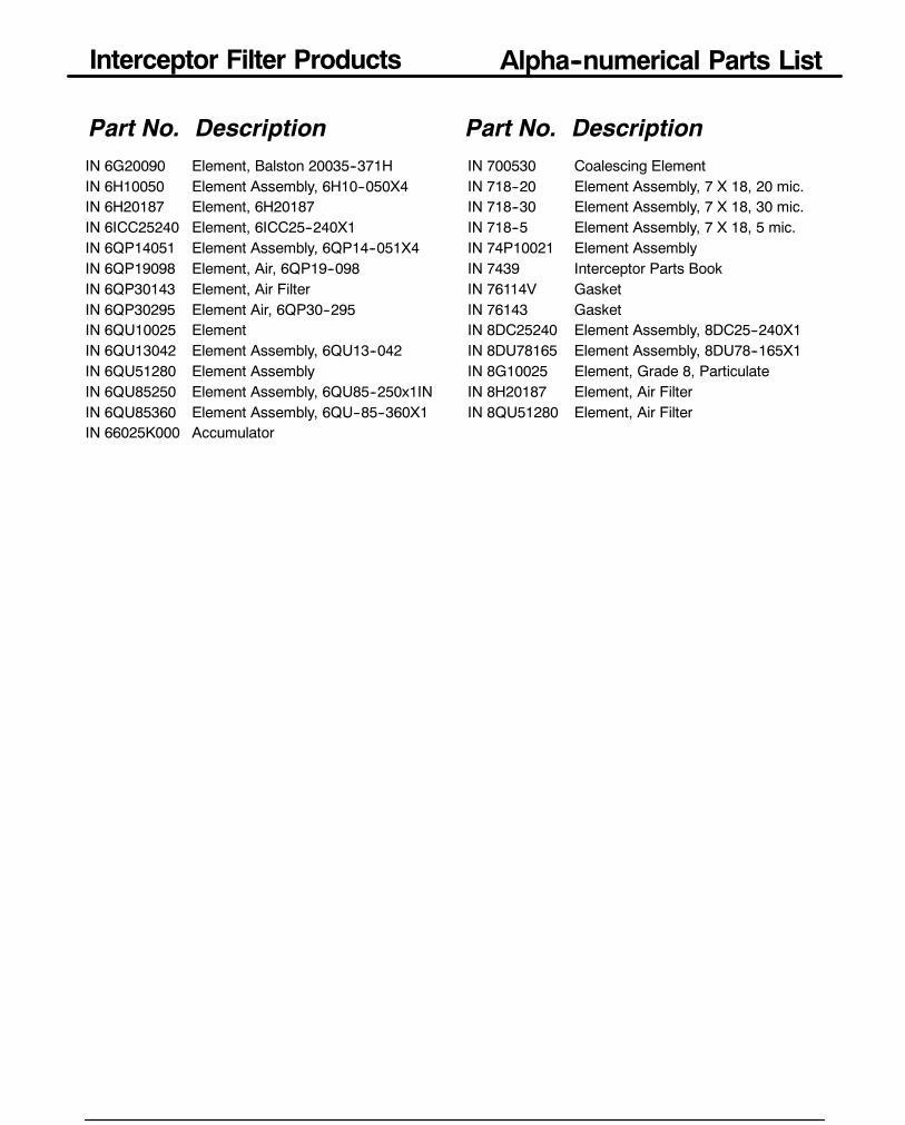
Interceptor Filter Products Alpha--numerical Parts List
189
Part No. Description Part No. DescriptionIN 6G20090 Element, Balston 20035--371HIN 6H10050 Element Assembly, 6H10--050X4IN 6H20187 Element, 6H20187IN 6ICC25240 Element, 6ICC25--240X1IN 6QP14051 Element Assembly, 6QP14--051X4IN 6QP19098 Element, Air, 6QP19--098IN 6QP30143 Element, Air FilterIN 6QP30295 Element Air, 6QP30--295IN 6QU10025 ElementIN 6QU13042 Element Assembly, 6QU13--042IN 6QU51280 Element AssemblyIN 6QU85250 Element Assembly, 6QU85--250x1ININ 6QU85360 Element Assembly, 6QU--85--360X1IN 66025K000 Accumulator
IN 700530 Coalescing ElementIN 718--20 Element Assembly, 7 X 18, 20 mic.IN 718--30 Element Assembly, 7 X 18, 30 mic.IN 718--5 Element Assembly, 7 X 18, 5 mic.IN 74P10021 Element AssemblyIN 7439 Interceptor Parts BookIN 76114V GasketIN 76143 GasketIN 8DC25240 Element Assembly, 8DC25--240X1IN 8DU78165 Element Assembly, 8DU78--165X1IN 8G10025 Element, Grade 8, ParticulateIN 8H20187 Element, Air FilterIN 8QU51280 Element, Air Filter

Racor Products Section 5 Lubrication Filtration Systems
Global FiltrationTechnology
Help & General Information
?
Selection
Full-Flow Cleanable
LFS 35
LFS 62/64
LFS 92
By-Pass Models
Spin-on Series
By-Pass Series
Accessories
Fittings
Troubleshooting
214
Lubrication Filtration Systems
Selection Information
GeneralRacor Lubrication Filtration Systems are permanent, full flow units which contain a reusable,stainless steel wire cloth filter which is designed to effectively trap damaging solids.
An added value of the wire cloth filter is its effectiveness as a visual diagnostic tool to monitorpotential enginewear. Cleanup of thewire cloth filter is easy. The filter can be soft brushed in solventor cleaned in a parts washer, then re--inserted between the permanent housings. Racor LubricationFiltration Systems (LFS) are available in two unique design configurations: A conventional’sandwich’ type and the new ’spin--on’ type.
The standard LFS ’sandwich’ type units utilize a flat disc shaped wire cloth filter that fits betweendie--cast aluminum housings. This cleanable filter design is available in a choice of micron ratingsThe standard oil filter is replaced by an adapter which spins onto the filter header. Adapters areavailable to fit virtually any engine.
The newSpin--on 700 Series feature a cylindrical shaped wire cloth filter that fits inside an aluminumhousing. Thismodel directly replaces the standard oil filter right on the engine ormay also be locatedin a convenient remote location.
Most Racor LFS systems come standard with a warning light feature. When the wire cloth filterreaches its restriction capacity, the system goes into a by--pass mode and the light signals theoperator there is a need for service. Frequency of filter cleansing is determined by the contaminationlevels present in the fluid. The cleaning interval may bemore frequent when first installed. The unitsare rated by the flow rate of the fluid.
The draining, crushing, accounting and related liabilities associated with used spin--on type filterdisposal are eliminated with these permanent filter designs.
1.DETERMINE THE TYPE OF LFS UNIT FOR YOUR APPLICATION:A. REMOTE MOUNT LFSB. SPIN--ON 700 SERIES, ENGINE MOUNTC. BY--PASS FILTRATION, REMOTE MOUNT
2.DETERMINE THE FLOW RATE OF THE FLUID TO BE FILTERED.You may also match a unit by the engine size as follows:LFS35: 6 GPM. Automatic transmissions, small engines, small motorcycles and AC power generators.LFS62 or 64: 20 GPM. Medium / heavy--duty applications, on and off--road and marine equipment.LFS92: 45 GPM. Large diesel engine oil, transmission and low pressure hydraulic return lines.LFS 700 Series. Large diesel engine oil: Caterpillar, Cummins, Detroit Diesel, Mack and Navistar.62 or 64BP: By--pass filtration, up to 20 GPM and 92BP: By--pass filtration up to 45 GPM.LFS 800 Series: By--pass filtration recommended for use with the LFS 700 Series filters.
3.DETERMINE THE DESIRED CLEANLINESS FOR THE SYSTEM:5 Micron: (.0002”) and10 Micron: (.0004”) are Recommended for by--pass oil filtration and hydraulic fluid.
Above filters not for use with full flow lubrication oil supply.28 Micron: (.0011”) Fine filtration recommended for engine oil and transmission filtration.40 Micron: (.0016”) Recommended for primary engine oil and transmission filtration.60 Micron: (.0024”) Recommended for coolant systems and hydraulic return lines.115 Micron: (.0045”) Porous filter, recommended for coolant systems.
Using this information, select a unit from the following page index. Also, refer to the specificliquid filtration unit information pages which follow.
Selection
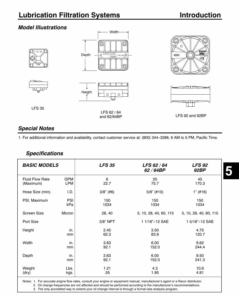
215
Lubrication Filtration Systems
Specifications
Model Illustrations
Special Notes
1. For additional information and availability, contact customer service at: (800) 344--3286, 6 AM to 5 PM, Pacific Time.
Height
Depth
LFS 35LFS 62 / 64and 62/64BP LFS 92 and 92BP
5
Introduction
Width
BASIC MODELS LFS 35 LFS 62 / 64 LFS 9262 / 64BP 92BP
Fluid Flow Rate GPM 6 20 45(Maximum) LPM 22.7 75.7 170.3
Hose Size (min). I.D. 3/8” (#6) 5/8” (#10) 1” (#16)
PSI, Maximum PSI 150 150 150kPa 1034 1034 1034
Screen Size Micron 28, 40 5, 10, 28, 40, 60, 115 5, 10, 28, 40, 60, 115
Port Size 3/8” NPT 1 1/16”--12 SAE 1 5/16”--12 SAE
Height in. 2.45 3.50 4.75mm 62.3 83.9 120.7
Width in. 3.63 6.00 9.62mm 92.1 152.0 244.4
Depth in. 3.63 6.00 9.50mm 92.1 152.0 241.3
Weight Lbs. 1.21 4.3 10.6(dry) kgs. .55 1.95 4.81
Notes: 1. For accurate engine flow rates, consult your engine or equipment manual, manufacturer’s agent or a Racor distributor.2. Oil change frequencies are not affected and should be performed according to the manufacturer’s recommendations.3. The only accredited way to extend your oil change interval is through a formal lube analysis program.
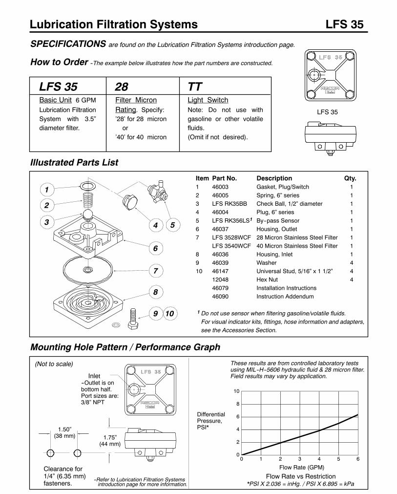
216
Lubrication Filtration Systems
LFS 35Basic Unit 6 GPMLubrication FiltrationSystem with 3.5”diameter filter.
Illustrated Parts List
SPECIFICATIONS are found on the Lubrication Filtration Systems introduction page.
LFS 35
How to Order --The example below illustrates how the part numbers are constructed.
(Not to scale)
--Refer to Lubrication Filtration Systemsintroduction page for more information.
1.50”(38 mm) 1.75”
(44 mm)
0
2
4
6
8
10
0 1 2 3 4 5 6
Mounting Hole Pattern / Performance Graph
Flow Rate (GPM)
DifferentialPressure,PSI*
These results are from controlled laboratory testsusing MIL--H--5606 hydraulic fluid & 28 micron filter.Field results may vary by application.
28Filter MicronRating. Specify:’28’ for 28 micronor
’40’ for 40 micron
TTLight SwitchNote: Do not use withgasoline or other volatilefluids.(Omit if not desired).
LFS 35
Flow Rate vs Restriction*PSI X 2.036 = inHg. / PSI X 6.895 = kPa
Inlet--Outlet is onbottom half.Port sizes are:3/8” NPT
Clearance for1/4” (6.35 mm)fasteners.
8
9 10
7
6
2
1
3 4 5
Item Part No. Description Qty.1 46003 Gasket, Plug/Switch 12 46005 Spring, 6” series 13 LFS RK35BB Check Ball, 1/2” diameter 14 46004 Plug, 6” series 15 LFS RK356LS1 By--pass Sensor 16 46037 Housing, Outlet 17 LFS 3528WCF 28 Micron Stainless Steel Filter 1
LFS 3540WCF 40 Micron Stainless Steel Filter 18 46036 Housing, Inlet 19 46039 Washer 410 46147 Universal Stud, 5/16” x 1 1/2” 4
12048 Hex Nut 446079 Installation Instructions46090 Instruction Addendum
1 Do not use sensor when filtering gasoline/volatile fluids.For visual indicator kits, fittings, hose information and adapters,see the Accessories Section.
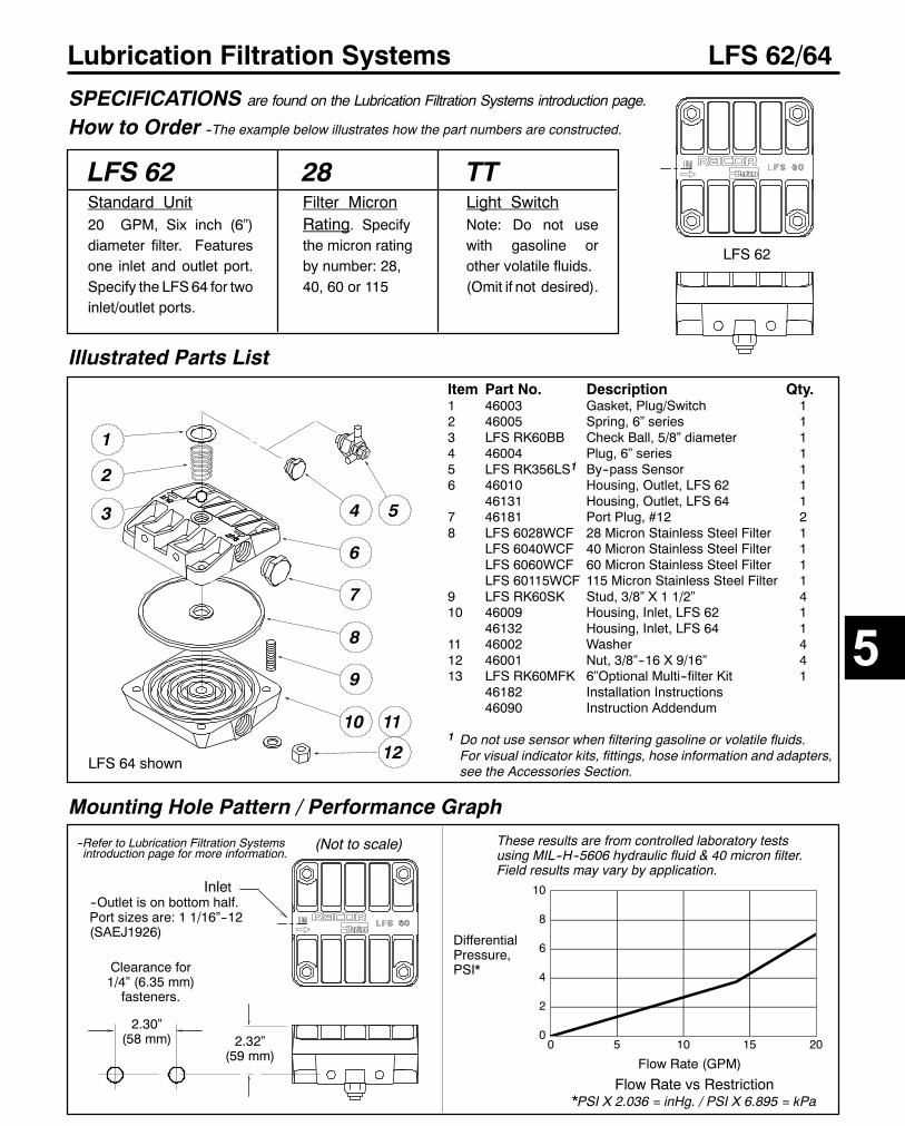
217
Lubrication Filtration Systems
Illustrated Parts List
SPECIFICATIONS are found on the Lubrication Filtration Systems introduction page.
How to Order --The example below illustrates how the part numbers are constructed.
(Not to scale)--Refer to Lubrication Filtration Systemsintroduction page for more information.
2.30”(58 mm) 0
2
4
6
8
10
0 5 10 15 20
Mounting Hole Pattern / Performance Graph
Flow Rate (GPM)
DifferentialPressure,PSI*
These results are from controlled laboratory testsusing MIL--H--5606 hydraulic fluid & 40 micron filter.Field results may vary by application.
Flow Rate vs Restriction*PSI X 2.036 = inHg. / PSI X 6.895 = kPa
Inlet--Outlet is on bottom half.Port sizes are: 1 1/16”--12(SAEJ1926)
Clearance for1/4” (6.35 mm)fasteners.
9
10 11
8
7
2
1
3 4 5
Item Part No. Description Qty.1 46003 Gasket, Plug/Switch 12 46005 Spring, 6” series 13 LFS RK60BB Check Ball, 5/8” diameter 14 46004 Plug, 6” series 15 LFS RK356LS1 By--pass Sensor 16 46010 Housing, Outlet, LFS 62 1
46131 Housing, Outlet, LFS 64 17 46181 Port Plug, #12 28 LFS 6028WCF 28 Micron Stainless Steel Filter 1
LFS 6040WCF 40 Micron Stainless Steel Filter 1LFS 6060WCF 60 Micron Stainless Steel Filter 1LFS 60115WCF 115 Micron Stainless Steel Filter 1
9 LFS RK60SK Stud, 3/8” X 1 1/2” 410 46009 Housing, Inlet, LFS 62 1
46132 Housing, Inlet, LFS 64 111 46002 Washer 412 46001 Nut, 3/8”--16 X 9/16” 413 LFS RK60MFK 6”Optional Multi--filter Kit 1
46182 Installation Instructions46090 Instruction Addendum
1 Do not use sensor when filtering gasoline or volatile fluids.For visual indicator kits, fittings, hose information and adapters,see the Accessories Section.
LFS 62
6
12
LFS 62/64
2.32”(59 mm)
LFS 62Standard Unit20 GPM, Six inch (6”)diameter filter. Featuresone inlet and outlet port.Specify the LFS64 for twoinlet/outlet ports.
28Filter MicronRating. Specifythe micron ratingby number: 28,40, 60 or 115
TTLight SwitchNote: Do not usewith gasoline orother volatile fluids.(Omit if not desired).
LFS 64 shown
5
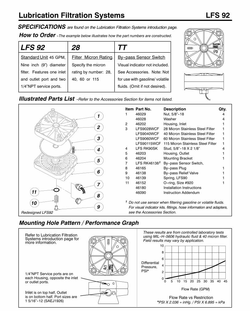
218
Lubrication Filtration Systems
Refer to Lubrication FiltrationSystems introduction page formore information.
0
2
4
6
8
10
0 5 10 15 20 25 30 35 40 45
Mounting Hole Pattern / Performance Graph
Flow Rate (GPM)
DifferentialPressure,PSI*
These results are from controlled laboratory testsusing MIL--H--5606 hydraulic fluid & 40 micron filter.Field results may vary by application.
Flow Rate vs Restriction*PSI X 2.036 = inHg. / PSI X 6.895 = kPa
Inlet is on top half, Outletis on bottom half. Port sizes are1 5/16”--12 (SAEJ1926)
4
3
2
Item Part No. Description Qty.1 46029 Nut, 5/8”--18 4
46028 Washer 42 46202 Housing, Inlet 13 LFS9028WCF 28 Micron Stainless Steel Filter 1
LFS9040WCF 40 Micron Stainless Steel Filter 1LFS9060WCF 60 Micron Stainless Steel Filter 1LFS90115WCF 115 Micron Stainless Steel Filter 1
4 LFS RK90SK Stud, 5/8”--18 X 2 1/8” 45 46203 Housing, Outlet 16 46204 Mounting Bracket 17 LFS RK461381 By--pass Sensor Switch,8 46165 By--pass Plug 19 46138 By--pass Relief Valve 110 46139 Spring, LFS90 111 46152 O--ring, Size #920 1
46180 Installation Instructions46090 Instruction Addendum
1 Do not use sensor when filtering gasoline or volatile fluids.For visual indicator kits, fittings, hose information and adapters,see the Accessories Section.
1
LFS 92
LFS 92StandardUnit 45 GPM,
Nine inch (9”) diameter
filter. Features one inlet
and outlet port and two
1/4”NPT service ports.
28Filter Micron Rating.
Specify the micron
rating by number: 28,
40, 60 or 115
TTBy--pass Sensor Switch
Visual indicator not included.
See Accessories. Note: Not
for use with gasoline/ volatile
fluids. (Omit if not desired).
Illustrated Parts List --Refer to the Accessories Section for items not listed.
SPECIFICATIONS are found on the Lubrication Filtration Systems introduction page.
How to Order --The example below illustrates how the part numbers are constructed.
Redesigned LFS92
1/4”NPT Service ports are oneach Housing, opposite the inletor outlet ports.
8
7
9
11
10
6
5
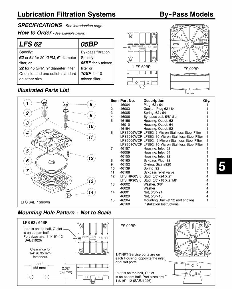
219
Lubrication Filtration Systems
Mounting Hole Pattern - Not to Scale
13
12
1
2
Item Part No. Description Qty.1 46004 Plug, 62 / 64 12 46003 Gasket, Plug 62 / 64 13 46005 Spring, 62 / 64 14 46006 By--pass ball, 5/8” dia. 15 46156 Housing, Outlet, 62 1
46010 Housing, Outlet, 64 146154 Housing, Outlet, 92 1
6 LFS6005WCF LFS62: 5 Micron Stainless Steel Filter 1LFS6010WCF LFS62: 10 Micron Stainless Steel Filter 1LFS9005WCF LFS92: 5 Micron Stainless Steel Filter 1LFS9010WCF LFS92: 10 Micron Stainless Steel Filter 1
7 46157 Housing, Inlet, 62 146009 Housing, Inlet, 64 146155 Housing, Inlet, 92 1
8 46165 By--pass Plug, 92 19 46152 O--ring, Size #920 110 46139 Spring, 92 111 46166 By--pass relief valve 112 LFS RK60SK Stud, 3/8”--24 X 2” 4
LFS RK90SK Stud, 5/8”--18 X 2 1/8” 413 46002 Washer, 3/8” 4
46028 Washer 414 46001 Nut, 3/8”--24 4
46029 Nut, 5/8”--18 415 46204 Mounting Bracket 92 (not shown) 1
46168 Installation Instructions
11
14
LFS 92BP
By--Pass Models
LFS 62Specify:62 or 64 for 20 GPM, 6” diameterfilter, or92 for 45 GPM, 9” diameter filter.One inlet and one outlet, standardon either size.
Illustrated Parts List
SPECIFICATIONS --See introduction page.
How to Order --See example below.
LFS 64BP shown
3
5
10
9
8
4
7
6
2.30”(58 mm)
Inlet is on top half, Outletis on bottom half.Port sizes are: 1 1/16”--12(SAEJ1926)
Clearance for1/4” (6.35 mm)fasteners.
2.32”(59 mm)
05BPBy--pass filtration.Specify:05BP for 5 micronfilter or10BP for 10micron filter.
LFS 62BP
5
Inlet is on top half, Outletis on bottom half. Port sizes are1 5/16”--12 (SAEJ1926)
1/4”NPT Service ports are oneach Housing, opposite the inletor outlet ports.
LFS 92BPLFS 62 / 64BP
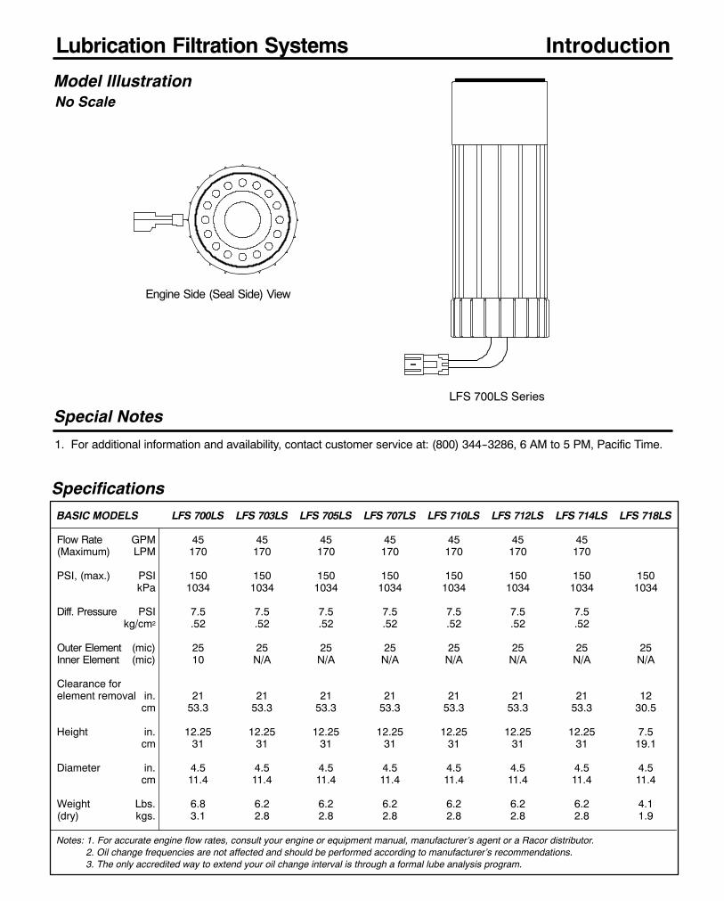
220
Lubrication Filtration Systems
Specifications
BASIC MODELS LFS 700LS LFS 703LS LFS 705LS LFS 707LS LFS 710LS LFS 712LS LFS 714LS LFS 718LS
Flow Rate GPM 45 45 45 45 45 45 45(Maximum) LPM 170 170 170 170 170 170 170
PSI, (max.) PSI 150 150 150 150 150 150 150 150kPa 1034 1034 1034 1034 1034 1034 1034 1034
Diff. Pressure PSI 7.5 7.5 7.5 7.5 7.5 7.5 7.5kg/cm2 .52 .52 .52 .52 .52 .52 .52
Outer Element (mic) 25 25 25 25 25 25 25 25Inner Element (mic) 10 N/A N/A N/A N/A N/A N/A N/A
Clearance forelement removal in. 21 21 21 21 21 21 21 12
cm 53.3 53.3 53.3 53.3 53.3 53.3 53.3 30.5
Height in. 12.25 12.25 12.25 12.25 12.25 12.25 12.25 7.5cm 31 31 31 31 31 31 31 19.1
Diameter in. 4.5 4.5 4.5 4.5 4.5 4.5 4.5 4.5cm 11.4 11.4 11.4 11.4 11.4 11.4 11.4 11.4
Weight Lbs. 6.8 6.2 6.2 6.2 6.2 6.2 6.2 4.1(dry) kgs. 3.1 2.8 2.8 2.8 2.8 2.8 2.8 1.9
Notes: 1. For accurate engine flow rates, consult your engine or equipment manual, manufacturer’s agent or a Racor distributor.2. Oil change frequencies are not affected and should be performed according to manufacturer’s recommendations.3. The only accredited way to extend your oil change interval is through a formal lube analysis program.
Model Illustration
Special Notes
1. For additional information and availability, contact customer service at: (800) 344--3286, 6 AM to 5 PM, Pacific Time.
Introduction
No Scale
Engine Side (Seal Side) View
LFS 700LS Series

221
Lubrication Filtration Systems
0
5
10
15
20
25
0 5 10 15 20 25 30 35 40 45
Applications List --Contact Racor Customer Service for applications not listed.
Flow Rate (GPM)
DifferentialPressure,PSI*
These results are from controlled laboratorytests using Turmco15 fluid & 25 micron filter.Field results may vary by application.
Flow Rate vs Restriction*PSI X 2.036 = inHg. / PSI X 6.895 = kPa
Item Part No. Description Qty.1 LFSRK755 Seal Kit (700--714LS) 1
LFSRK758 Seal Kit (718LS) 12 46502--01 Housing, LFS 710LS 1
46502--02 Housing, LFS 703LS 146502--03 Housing, LFS 707LS 146502--04 Housing, LFS 712LS 146502--05 Housing, LFS 705LS 146502--06 Housing, LFS 700LS 146502--07 Housing, LFS 714LS 146502--08 Housing, LFS 718LS 1
3 LFSRK750 Element, Outer (Dual element only) 14 LFSRK751 Element, Inner (Dual element only) 1
LFSRK759 Element, (703--714LS Series) 1LFSRK757 Element, (718LS only) 1
5 46574 Element Retainer, Outer 16 46521 Spring, Main Compression 17 LFSRK753 End Cap, LFS 700LS Series 1
46539 700 Series Installation Instructions8 46013 Light and Panel Kit, 12V 19 46065 Light Only 1
1
LFS 700LS Series
LFS 700LSModel: Center Mounting Thread. Specify one:
700LS: 2 1/4”--12 710LS: 1 3/8”--16
703LS: 1 1/2”--12 712LS: 1 1/2”--16
705LS: 1 5/8”--12 714LS: 36M X 1.5
707LS: 1 1/8”--16 718LS: 1 1/2”--16
Illustrated Parts List --Refer to the Accessories Section for items not listed.
SPECIFICATIONS are found on the Lubrication Filtration Systems introduction page.
How to Order --The example below illustrates how the part numbers are constructed.
5
LFS 700LS Series
2
3
4
5
6
7
Engine Make Engine Model LFS Model
CATERPILLAR 3116, 3208T, 3304, 3306 LFS 707LS3176, 3406, 3408, 3412, C10, C12 LFS 712LS
CUMMINS All engines using LF--3000combination full flow by--pass filter LFS 700LSC Series, L10, N--14, Big Cam IV230, 240, NTC--250, 290, 300350, 355, 370, 400, All KT LFS 703LS
DETROIT *Series 50 & 60, 1993 MY and on LFS 705LSKTAll 53, 71, 92, 149 Series &Pre ’93 Series 60 LFS 703LS
MACK TRUCK EM--6, EN, ENDT,*EM--7 LFS707LSKTNAVISTAR 6.9, 7.3, 7.3 Power Stroke LFS 718LS
DT--466, 1994 and on LFS 714LS*Some engines use 2 filters. The KT kit provides 2 filter Assemblies.
8
Lubrication Filtration Systems.Spin--on oil filter with cleanableand reusable stainless steelcartridge for diesel engines.Includes internal by--pass (opensat 24 PSID) with differentialpressure sensor switch and panelmount indicator.
9
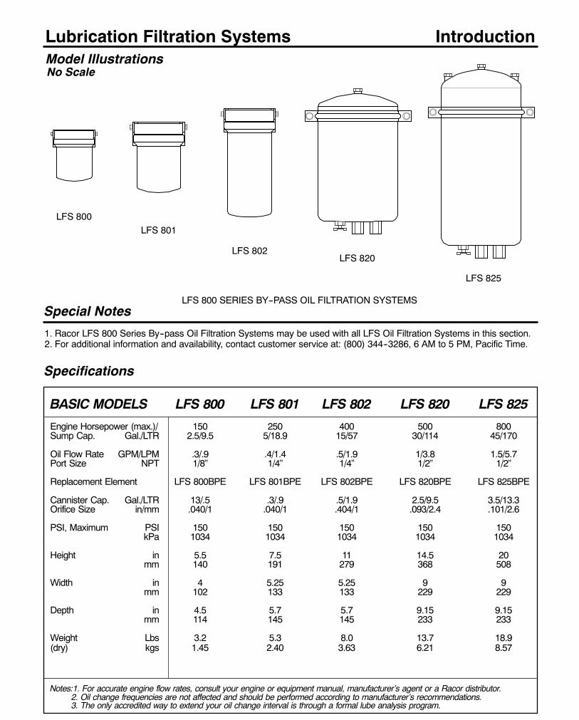
222
Lubrication Filtration Systems
Specifications
Model Illustrations
Special Notes
1. Racor LFS 800 Series By--pass Oil Filtration Systems may be used with all LFS Oil Filtration Systems in this section.2. For additional information and availability, contact customer service at: (800) 344--3286, 6 AM to 5 PM, Pacific Time.
LFS 825
Introduction
LFS 820LFS 802
LFS 801
LFS 800 SERIES BY--PASS OIL FILTRATION SYSTEMS
BASIC MODELS LFS 800 LFS 801 LFS 802 LFS 820 LFS 825
Engine Horsepower (max.)/ 150 250 400 500 800Sump Cap. Gal./LTR 2.5/9.5 5/18.9 15/57 30/114 45/170
Oil Flow Rate GPM/LPM .3/.9 .4/1.4 .5/1.9 1/3.8 1.5/5.7Port Size NPT 1/8” 1/4” 1/4” 1/2” 1/2”
Replacement Element LFS 800BPE LFS 801BPE LFS 802BPE LFS 820BPE LFS 825BPE
Cannister Cap. Gal./LTR 13/.5 .3/.9 .5/1.9 2.5/9.5 3.5/13.3Orifice Size in/mm .040/1 .040/1 .404/1 .093/2.4 .101/2.6
PSI, Maximum PSI 150 150 150 150 150kPa 1034 1034 1034 1034 1034
Height in 5.5 7.5 11 14.5 20mm 140 191 279 368 508
Width in 4 5.25 5.25 9 9mm 102 133 133 229 229
Depth in 4.5 5.7 5.7 9.15 9.15mm 114 145 145 233 233
Weight Lbs 3.2 5.3 8.0 13.7 18.9(dry) kgs 1.45 2.40 3.63 6.21 8.57
Notes:1. For accurate engine flow rates, consult your engine or equipment manual, manufacturer’s agent or a Racor distributor.2. Oil change frequencies are not affected and should be performed according to manufacturer’s recommendations.3. The only accredited way to extend your oil change interval is through a formal lube analysis program.
LFS 800
No Scale

223
Lubrication Filtration Systems
General Information
LFS 700Series
LFSBy--PassUnit
To oil panor valvecover.
Model Part Number Qty./case Seal Kit No.
LFS 800 LFS 800BPE 1 LFS RK46581
LFS 801 LFS 801BPE 1 LFS RK46582
LFS 802 LFS 802BPE 1 LFS RK46582
LFS 820 LFS 820BPE 1 LFS RK46583
LFS 825 LFS 825BPE 1 LFS RK46583
By--Pass Models
801Specify one by engine horsepower.
800: 150 Horsepower
801: 250 Horsepower
802: 400 Horsepower
820: 500+ Horsepower
825: 800+ Horsepower
Replacement Filter Elements / Seals
SPECIFICATIONS -- See introduction page.
How to Order -- See example below.
5Racor By--pass Oil Filtration Systems are unique in their configuration. They feature a spin--onsteel canister mounted to an aluminum head. The cartridge spin--on element is made of a com-puter wound, cotton woven media. The engineered design of the filter element provides moreefficient filtration for a significantly longer period of time than pleated cellulose, stacked discs,and other cartridge filters
When a Racor By--pass Oil Filter is installed with a Racor Full Flow Lubrication Filtration System(LFS), the cost of lube oil, replacement filter, related disposal and maintenance are drasticallyreduced.
Lubrication Filtration
Systems. By--pass
oil filters for gas and
diesel engines.
LFS
LFS 802
LFS 820/825
Bypass Hose Kit Number
LFS 801BHK. Available
for LFS 801 and LFS 802
models.
InletOutlet

224
Lubrication Filtration Systems
Kit Part No. Description / Notes Use with: Qty.
LFS RK356LS Standard By--pass Sensor Switch LFS35, 55 & 60 1Do not use above kits when filtering gasoline or other volatile fluids.
LFS RK46138 By--pass Sensor Switch LFS92 1Do not use above kits when filtering gasoline or other volatile fluids.
LFS RK760 Oil Analysis Kit All Models 1Use this kit to determine extended oil change intervals while usingour By--Pass filtration units.
Fluid By-pass Sensor Switch Kits
Light Display Kits
Accessories/Fittings
TYPICAL ADAPTERKits include seal.
Spin-on Oil Filter Adapter & Replacement O-ring Kits
Complete *Replacement Adapter to Adapter in/out (O’berg No.)Kit Part No. Seal kit Part No. engine threads port threads
LFS CHV--A N/A 1/4”--20 (2)5/16”--18(2) 1/2”--14 NPTF 233LFS 112--36A RK 46169 1”--12 1/2”--14 NPTF 214LFS 11212--48A RK 46045 1 1/2”--12 1 5/16”--12 SAE 212LFS 11216--41A RK 46170 1 1/2”--16 1/2”--14 NPTF 269LFS 11216--48A RK 46045 1 1/2”--16 1 5/16”--12 SAE 219LFS 11216--50A N/A 1 1/2”--16 1 5/16”--12 SAE 247LFS 116--36A RK 46169 1”--16 1/2”--14 NPTF 252LFS 11816--36A RK 46169 1 1/8”--16 1/2”--14 NPTF 225LFS 11816--48A RK 46045 1 1/8”--16 1 5/16”--12 SAE 218LFS 1316--36A RK 46169 13/16”--16 1/2”--14 NPTF 222LFS 13816--48A RK 46045 1 3/8”--16 1 5/16”--12 SAE 210LFS 15812--48A RK 46045 1 5/8”--12 1 5/16”--12 SAE N/ALFS 1815--31A RK 46169 18 mm X 1.5 1/2”--14 NPTF 250LFS 2015--31A** RK 46169 20 mm X 1.5 1/2”--14 NPTF 232LFS 2015--36A RK 46169 20 mm X 1.5 1/2”--14 NPTF 231LFS 2215--31A RK 46169 22 mm X 1.5 1/2”--14 NPTF 223LFS 3416--31A RK 46169 3/4”--16 1/2”--14 NPTF 213LFS 5818--31A RK 46169 5/8”--18 1/2”--14 NPTF 251
*O--ring or gasket should be replaced if adapter is removed from engine, after being in service.RK 46169: Gasket, 2.48”I.D. RK 46045: O--ring, 3.73”I.D. RK 46170: Gasket, 3.10”I.D.**Includes a spacer plate.
Kit Part No. Description / Notes Use with: Qty.
LFS RK356LSK Complete By--pass Light Display KitIncludes By--pass Sensor also. 12 vdc. LFS35, 55, 62 & 64 1
46032 By--pass Light Display only. 12 vdc. LFS 92, 700 Series 146536 Connector Assembly with Relay (not shown) LFS 700 Series 1
LFS RK46134 In--dash Light Display, 12 / 24 vdc.Informs the operator when filterservicing is required. Features a 10 min.timed delay to eliminate false readings.Light stays on until filter is serviced.Panel press--to--test buttons. Fits 2”diameter openings. Includes bracket forunderdash mounting also. Order By--passSensor Switch separately (see above). LFS35, 62, 64, & 92 1
Do not use above kits when filtering gasoline or other volatile fluids.
Portthreads
Adapter toengine threads(not shown).
*O--ring or gasketalso available as a
replacement.
LFS RK356LSK46032
LFS RK46134
LFS RK356LS
LFS RK46138
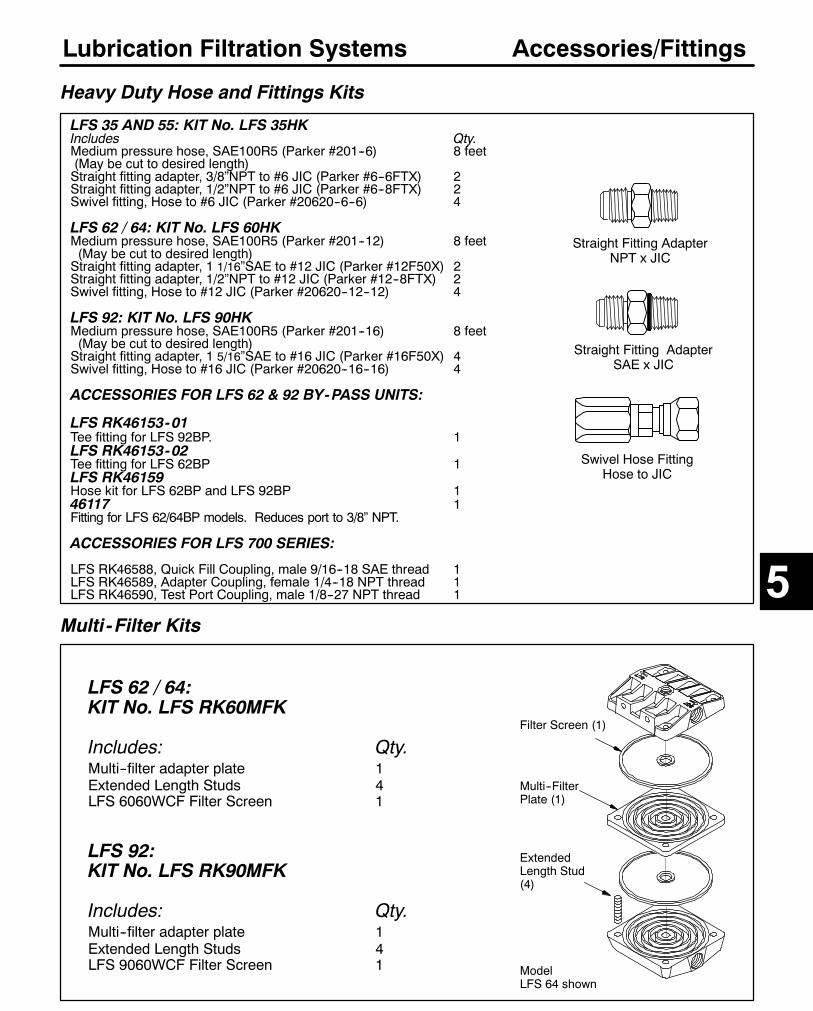
225
Lubrication Filtration Systems
LFS 62 / 64:KIT No. LFS RK60MFK
Includes: Qty.Multi--filter adapter plate 1Extended Length Studs 4LFS 6060WCF Filter Screen 1
LFS 92:KIT No. LFS RK90MFK
Includes: Qty.Multi--filter adapter plate 1Extended Length Studs 4LFS 9060WCF Filter Screen 1
Multi-Filter Kits
Accessories/Fittings
Filter Screen (1)
Multi--FilterPlate (1)
ExtendedLength Stud(4)
ModelLFS 64 shown
LFS 35 AND 55: KIT No. LFS 35HKIncludes Qty.Medium pressure hose, SAE100R5 (Parker #201--6) 8 feet(May be cut to desired length)Straight fitting adapter, 3/8”NPT to #6 JIC (Parker #6--6FTX) 2Straight fitting adapter, 1/2”NPT to #6 JIC (Parker #6--8FTX) 2Swivel fitting, Hose to #6 JIC (Parker #20620--6--6) 4
LFS 62 / 64: KIT No. LFS 60HKMedium pressure hose, SAE100R5 (Parker #201--12) 8 feet(May be cut to desired length)Straight fitting adapter, 1 1/16”SAE to #12 JIC (Parker #12F50X) 2Straight fitting adapter, 1/2”NPT to #12 JIC (Parker #12--8FTX) 2Swivel fitting, Hose to #12 JIC (Parker #20620--12--12) 4
LFS 92: KIT No. LFS 90HKMedium pressure hose, SAE100R5 (Parker #201--16) 8 feet(May be cut to desired length)Straight fitting adapter, 1 5/16”SAE to #16 JIC (Parker #16F50X) 4Swivel fitting, Hose to #16 JIC (Parker #20620--16--16) 4
ACCESSORIES FOR LFS 62 & 92 BY-PASS UNITS:
LFS RK46153-01Tee fitting for LFS 92BP. 1LFS RK46153-02Tee fitting for LFS 62BP 1LFS RK46159Hose kit for LFS 62BP and LFS 92BP 146117 1Fitting for LFS 62/64BP models. Reduces port to 3/8” NPT.
ACCESSORIES FOR LFS 700 SERIES:
LFS RK46588, Quick Fill Coupling, male 9/16--18 SAE thread 1LFS RK46589, Adapter Coupling, female 1/4--18 NPT thread 1LFS RK46590, Test Port Coupling, male 1/8--27 NPT thread 1
Heavy Duty Hose and Fittings Kits
Straight Fitting AdapterNPT x JIC
Straight Fitting AdapterSAE x JIC
Swivel Hose FittingHose to JIC
5

226
Lubrication Filtration SystemsQuick Help Guide: All ModelsALL RACOR LFS MODELS ARE 100% TESTED TO ENSURE A LEAK--PROOF, QUALITY PRODUCT.
In theevent difficulties areexperiencedwith your unit review the followingmost commonquestions askedaboutthe LFS units:
WARNING LAMP REMAINS ILLUMINATED:Q.What causes the warning lamp on the LFS 35, 55, 62, 64, 92, 94, and 700LS Series to stay on and not go off?
A. This lamp indicates that the filter screen is dirty. On initial installations, the screen may appear to clog ina rather short time. This is normal for the first few ’clean--up’ cycles. Thereafter, the frequency should stabilizeand occur less often. If the lamp stays on after a cleaning, investigate the following:
LFS 35, 55, 62, 64, 92, and 94: With the filter halves separated and power supplied to the light switch,depress and release the by--pass mechanism. The light should be on when the by--pass is pushed down andgo out when released. If the light switch does not function as indicated above, it will have to be replaced.
Note: It is important that the clear plastic insulator gasket between the switch and filter body be used andnot distorted due to over tightening of the switch. If this gasket is missing, the warning lamp will stay on.
LFS 700LS Series: The LFS 700 Series light switch is normally closed when the light is off. If the lamp isilluminated, there are several possible reasons: the filter is dirty, there is an open circuit in the endcap, thereis an open circuit in the connector plug, the connector plug is disconnected, there is an open circuit betweenthe endcap and the relay, or there is a bad relay.
WARNING LAMP FLICKERS ON/OFF WHEN ENGINE IS FIRST STARTED:Q. What causes the lamp to flicker on and off when I first start the engine?
A. Thiswill sometimes happen on a coldmorning due to the thicker viscosity of the oil. Pushing cold oil throughthe element can build up enough pressure against the by--pass to cause the light to try to come on. The originalequipment oil filter that you replaced when installing the LFS creates nearly twice the back pressure andgenerally goes into completeby--passunder these conditions. OnlyRacor’s LFS is sensitiveenough to indicatethis insignificant amount of by--pass. The lampmust remain fully illuminated before a serious by--pass occurs.
FILTER CONTAMINATION:Q. When I open the filter it appears clean but the bottom side of it is full of particulates and debris.
A. This filter is plumbed backwards so the contaminants are on the ’wrong’ side. If this happens, the unit willcontinue to filter until plugged and then it will hold the by--pass valve closed, and will not allow the light to comeon. This will stop oil flow to the engine unless there is a built--in, by--pass relief valve in the engine.The Racor engine spin--on filter adapter replacements are marked IN and OUT or have arrows indicating flowdirection. The LFS oil filter housings are also clearly marked IN and OUT or have arrows indicating flowdirection.NOTE: Do not match IN to IN or OUT to OUT! Remember the oil flows out from the engine and in to the filter.Then, it flows out of the filter and back into the engine.
Q. How do I determine which filter to use for a given application?
A. Refer to the LFSapplication guide for remotemount units, the adapter part number and recommended filtersize will be listed. If you have a non listed or specialized application, size the filter by flow rate capacity andthe adapter by comparing the OEM specification for thread and gasket dimensions. The flow rate specs foreach filter are listed the the 7460 brochure and in this parts book.
The application guide for the cleanable Spin--on 700LS Series is on page 221.
For additional assistance, call your Racor Dealer or Racor Customer Service at (209) 521--7860 or (800)344--3286, 6 AM to 5 PM, Pacific Time, or e--mail us from our website, www.parker.com/racor.
Troubleshooting
Racor Products Section 6 Alternative Fuels
Global FiltrationTechnology
Help & General Information
?
Selection
Introduction
FFC-110/110L
FFC-112/112SAE
FFC-113
FFC-114
FFC-115
FFC-116
FFC-119

231
SECTION 6
Model Fuel Filter Pressure Flow Rate Port PageTypes Type PSI SCFM Sizes
FFC--110 CNG, LPG Coalescer 500 25 1/4” NPT 232, 234FFC--110L CNG, LNG, LPG Coalescer 500 50 1/2” NPT 232, 234FFC--112 CNG Coalescer 3600 15 1/4” NPT 232, 235FFC--112--SAE CNG Coalescer 3600 15 9/16” SAE 232, 235FFC--113 CNG, LNG Coalescer 3600 50 1/2” NPT 232, 236FFC--113--NF CNG, LNG Coalescer 3600 50 3/4” SAE 233, 236FFC--114 CNG, LNG Coalescer 3600 50 1/2” NPT 233, 237FFC--114--NF CNG, LNG Coalescer 3600 50 3/4” SAE 233, 237FFC--115 LNG Coalescer 3600 60 1” NPT 233, 238FFC--116 CNG Coalescer 5000 8.4 1/4” NPT 233, 239FFC--119 LPG Prefilter/Strainer 500 N/A 1/4” Inlet
5/8” Outlet 233, 240
IndexAlternative Fuel Filtration Systems
GeneralRacor Alternative Fuel Filtration products are designed to protect critical engine components incompressed natural gas (CNG), liquid natural gas (LNG) and liquid propane gas (LPG) poweredvehicles. Contaminants can be introduced into the vehicle’s fuel tank when being fueled.Contaminants may come from CNG compressors and storage facilities. These units are specificallydesigned to remove oil, water and solid contamination from compressed natural gas. The specialcoalescing filters remove over 95% of all aerosols in the 0.3 to 0.6 micron range.
1. DETERMINE THE ALTERNATE FUEL TO BE FILTERED: CNG, LNG OR LPG.
2. DETERMINE THE SYSTEM PRESSURE FOR THE MOUNTING LOCATION.The pressure may be found by contacting the vehicle or engine manufacturer.To convert kilopascals (kPa) to PSI, divide kPa by 6.8947.
3. DETERMINE THE SYSTEM FLOW RATE IN SCFM*.The flow rate may be found by contacting the vehicle or engine manufacturer.*(Standard Cubic Feet per Minute or SCFM, calculated at 100 PSIG).To convert liters per minute (LPM) to SCFM, multiply LPM by .0353).To convert pounds per hour (PPH) to SCFM, divide PPH by 60 and then divide by .0447.
Using this information, select a unit for service from this page that suits your application andfits within installation size limitations (if any).
Selection
6
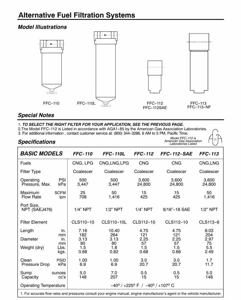
232
Alternative Fuel Filtration Systems
Specifications
BASIC MODELS FFC-110 FFC-110L FFC-112 FFC-112-SAE FFC-113
Fuels CNG, LPG CNG,LNG,LPG CNG CNG CNG,LNG
Filter Type Coalescer Coalescer Coalescer Coalescer Coalescer
Operating PSI 500 500 3,600 3,600 3,600Pressure, Max. kPa 3,447 3,447 24,800 24,800 24,800
Maximum SCFM 25 50 15 15 50Flow Rate lpm 708 1,416 425 425 1,416
Port Size,NPT (SAEJ476) 1/4” NPT 1/2” NPT 1/4” NPT 9/16”--18 SAE 1/2” NPT
Filter Element CLS110--10 CLS110--10L CLS112--10 CLS112--10 CLS113--6
Length in. 7.16 10.40 4.75 4.75 8.03mm 182 264 121 121 204
Diameter in. 3.13 3.13 2.25 2.25 2.97mm 80 80 57 57 75
Weight (dry) Lbs. 1.5 1.8 1.5 1.5 5.5kgs. 0.68 0.82 0.68 0.68 2.49
Clean PSID 1.00 1.00 3.0 3.0 1.7Pressure Drop kPa 6.9 6.9 20.7 20.7 11.7
Sump ounces 5.0 7.0 0.5 0.5 5.0Capacity cc’s 148 207 15 15 148
Operating Temperature --40o / +225o F / --40o / +107o C
1. For accurate flow rates and pressures consult your engine manual, engine manufacturer’s agent or the vehicle manufacturer.
Model Illustrations
Special Notes
1. TO SELECT THE RIGHT FILTER FOR YOUR APPLICATION, SEE THE PREVIOUS PAGE.2.The Model FFC--112 is Listed in accordance with AGA1--85 by the American Gas Association Laboratories.3. For additional information , contact customer service at: (800) 344--3286, 6 AM to 5 PM, Pacific Time.
FFC--110 FFC--112FFC--112SAE
FFC--113FFC--110L
Model FFC--112 isAmerican Gas Association
Laboratories Listed
FFC--113--NF
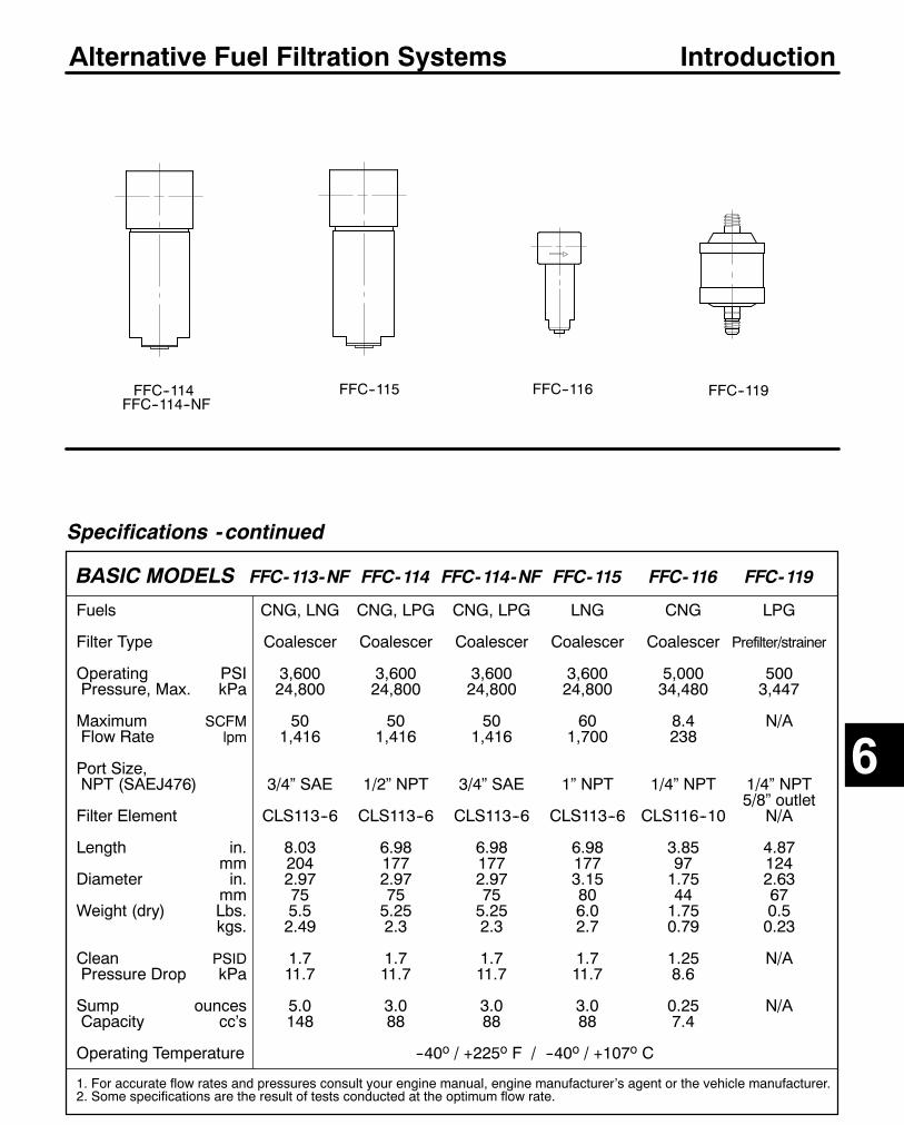
233
Alternative Fuel Filtration Systems
Specifications -continued
BASIC MODELS FFC-113-NF FFC-114 FFC-114-NF FFC-115 FFC-116 FFC-119
Fuels CNG, LNG CNG, LPG CNG, LPG LNG CNG LPG
Filter Type Coalescer Coalescer Coalescer Coalescer Coalescer Prefilter/strainer
Operating PSI 3,600 3,600 3,600 3,600 5,000 500Pressure, Max. kPa 24,800 24,800 24,800 24,800 34,480 3,447
Maximum SCFM 50 50 50 60 8.4 N/AFlow Rate lpm 1,416 1,416 1,416 1,700 238
Port Size,NPT (SAEJ476) 3/4” SAE 1/2” NPT 3/4” SAE 1” NPT 1/4” NPT 1/4” NPT
5/8” outletFilter Element CLS113--6 CLS113--6 CLS113--6 CLS113--6 CLS116--10 N/A
Length in. 8.03 6.98 6.98 6.98 3.85 4.87mm 204 177 177 177 97 124
Diameter in. 2.97 2.97 2.97 3.15 1.75 2.63mm 75 75 75 80 44 67
Weight (dry) Lbs. 5.5 5.25 5.25 6.0 1.75 0.5kgs. 2.49 2.3 2.3 2.7 0.79 0.23
Clean PSID 1.7 1.7 1.7 1.7 1.25 N/APressure Drop kPa 11.7 11.7 11.7 11.7 8.6
Sump ounces 5.0 3.0 3.0 3.0 0.25 N/ACapacity cc’s 148 88 88 88 7.4
Operating Temperature --40o / +225o F / --40o / +107o C
1. For accurate flow rates and pressures consult your engine manual, engine manufacturer’s agent or the vehicle manufacturer.2. Some specifications are the result of tests conducted at the optimum flow rate.
FFC--116
6
FFC--119FFC--115FFC--114
Introduction
FFC--114--NF

234
Alternative Fuel Filtration Systems FFC--110, FFC--110LSPECIFICATIONS are found on Alternative Fuel Filtration introduction page.
Replacement Coalescing Service Elements
FFC--110L
FFC-110FFC--110:25 SCFM/500 PSICoalescer. Black powdercoating on 380 aluminumhead and 6061 cannisterwith standard 1/4” NPTFports and standard Grade10 element.FFC--110L:50 SCFM/500 PSI
FEATURES-- For use with CNG, LPG (FCC--110L: also LNG).-- Durable construction and simple servicing.-- Small size allows for installation versatility.-- Patented filter removes over 95% of all aerosols inthe 0.3 to 0.6 micron range.
-- FFC--110 sump capacity = 5 oz. (148 cc)FFC--110L sump capacity = 7.0 oz. (207 cc) of fluidcontaminants.
-- Assemblies are powder painted for long termcorrosion protection.
Installation Diagram / Dimensional Layout
FFC-110CLS110--04 Grade 4, elementCLS110--3M 3 micron elementCLS110--06 Grade 6, elementCLS110--10 Grade 10, element
FFC--110:Inlet and outletports are:1/4”--18 NPTF(SAEJ476)
FFC--110L:Inlet and outletports are:1/2”--14 NPTF(SAEJ476)
Drain
EngineFuelTank
Shut--offValve Pressure
Regulator
FlowDirection
Installation NoteThe unit should be located in an accessible andprotected location for easy servicing.Use connectors approved by the American GasAssociation and the Department of Transportation.Test the installation for leaks using an approved leakdetection fluid.
Service Note Caution:The unit must not be under pressure duringservicing. Injury to personnel may result. Close theshut--off valve shown in the illustration above andslowly relieve line pressure before attemptingservice.
Replacing the ElementChange the element at the same time as engine oilfilter changes or at least every 3,000 miles.
Draining the HousingDrain the housing every 1,500 miles or asnecessary. With line pressure relieved, open valveand drain until liquid is removed, then close thevalve.
1/4”--20 SAE (2)
1.32”(33 mm)
FFC--110:7.92”
(201 mm)FFC--110L:
10.4”(264 mm)
3.13”(80 mm)
.56”(14mm)
FLOW
FLOW
Typical installation layoutNote: FFC--110 and FFC--110L MaximumOperating pressure is 500 PSI.
FFC-110LCLS110L--04 Grade 4, elementCLS110L--3M 3 micron elementCLS110L--06 Grade 6, elementCLS110L--10 Grade 10, element

235
Alternative Fuel Filtration Systems FFC--112, FFC--112--SAE
SPECIFICATIONS are found on Alternative Fuel Filtration introduction page.
Replacement Service Element
FFC--112FFC--112--SAE
FFC-112FFC--112: 15 SCFM/3,600 PSI,Coalescer. Black anodizedcoating on 6061--T6 aluminumhead and cannister with stan-dard 1/4” NPTF ports andGrade 10 element.
FFC--112--SAE: 9/16”--18 SAEports.
FEATURES-- For use with CNG systems.-- Listed with the American Gas Association.-- Durable construction and simple servicing.-- Small size allows for installation versatility.-- Patented filter removes over 95% of allaerosols in the 0.3 to 0.6 micron range.
-- Sump capacity up to .5 oz. (15 cc) ofcontaminants.
-- Maximum burst pressure of 15,000 PSI.
Installation Diagram / Dimensional Layout
CLS112-10 Grade 10, coalescing service element
FFC--112:Head is 2.25”(57 mm)diameter.Inlet and outletports are: 1/4”--18NPTF(SAEJ476)
FFC--112--SAE:Inlet and outletports are:9/16”--18 SAEO--ring ports(SAEJ1926)
Drain plug
EngineFuelTank
Shut--offValve Pressure
Regulator
FlowDirection
Installation NoteThe unit should be located in an accessible and protectedlocation for easy servicing.Use connectors approved by the American Gas Associationand the Department of Transportation.Maintain at least 3” (76 mm) of clearance below the unit forelement access.Test the installation for leaks using an approved leak detectionfluid.
Service Note Caution:The unit must not be under pressure during servicing. Injury topersonnel may result. Close the shut--off valve shown in theillustration above and slowly relieve line pressure beforeattempting service.
Replacing the ElementChange the element at the same time as engine oil filterchanges or at least every 3,000 miles.
Draining the HousingDrain the housing every 1,500miles or as necessary. With linepressure relieved, remove the drain plug using a 1/4” Allenwrench, then replace the plug.
5/16”--18 SAE (2)
Typical installation layout
American Gas AssociationLaboratories Listed
FFC--112
.50”(13 mm)
4.75”(121 mm)
1.38”(35 mm)
2.13”(54 mm)
1.37”
1.88”(48 mm)
Maintain at least 3” (76 mm) of clear-ance below the unit for element access.
6
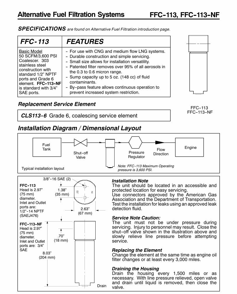
236
Alternative Fuel Filtration Systems FFC--113, FFC--113--NF
SPECIFICATIONS are found on Alternative Fuel Filtration introduction page.
Replacement Service ElementFFC--113
FFC-113Basic Model50 SCFM/3,600 PSICoalescer. 303stainless steelconstruction withstandard 1/2” NPTFports and Grade 6element. FFC--113--NFis standard with 3/4”SAE ports.
FEATURES-- For use with CNG and medium flow LNG systems.-- Durable construction and simple servicing.-- Small size allows for installation versatility.-- Patented filter removes over 95% of all aerosols inthe 0.3 to 0.6 micron range.
-- Sump capacity up to 5 oz. (148 cc) of fluidcontaminants.
-- By--pass feature allows continuous operation toprevent increased system restriction.
Installation Diagram / Dimensional Layout
CLS113-6 Grade 6, coalescing service element
FFC--113Head is 2.97”(75 mm)diameter.Inlet and Outletports are:1/2”--14 NPTF(SAEJ476)
FFC--113--NFHead is 2.97”(75 mm)diameter.Inlet and Outletports are: 3/4”SAE
Drain
EngineFuelTank
Shut--offValve
PressureRegulator
FlowDirection
Installation NoteThe unit should be located in an accessible andprotected location for easy servicing.Use connectors approved by the American GasAssociation and the Department of Transportation.Test the installation for leaks using an approved leakdetection fluid.
Service Note Caution:The unit must not be under pressure duringservicing. Injury to personnel may result. Close theshut--off valve shown in the illustration above andslowly relieve line pressure before attemptingservice.
Replacing the ElementChange the element at the same time as engine oilfilter changes or at least every 3,000 miles.
Draining the HousingDrain the housing every 1,500 miles or asnecessary. With line pressure relieved, open valveand drain until liquid is removed, then close thevalve.
3/8”--16 SAE (2)
1.38”(35 mm)
8.03”(204 mm)
2.63”(67 mm)
.70”(18 mm)
Typical installation layoutNote: FFC--113 Maximum Operatingpressure is 3,600 PSI.
FFC--113--NF

237
Alternative Fuel Filtration Systems FFC--114, FFC--114--NF
SPECIFICATIONS are found on Alternative Fuel Filtration introduction page.
Replacement Service Element FFC--114
FFC-114Basic Model50 SCFM/3,600 PSICoalescer. 303stainless steelconstruction withstandard 1/2” NPTFports and Grade 6element. FFC--114--NFis standard with 3/4”SAE ports.
FEATURES-- For use with CNG and medium flow LPG systems.-- Durable construction and simple servicing.-- Small size allows for installation versatility.-- Patented filter removes over 95% of all aerosols inthe 0.3 to 0.6 micron range.
-- Sump capacity up to 3 oz. (88 cc) of fluidcontaminants.
-- Stainless steel for superior corrosion resistance.-- By--pass feature allows continuous operation toprevent increased system restriction.
Installation Diagram / Dimensional Layout
CLS113-6 Grade 6, coalescing service element
FFC--114Head is 2.97”(75 mm)diameter.Inlet and Outletports are:1/2”--14 NPTF(SAEJ476)
FFC--114--NFHead is 2.97”(75 mm)diameter.Inlet and Outletports are: 3/4”SAE
Drain
EngineFuelTank
Shut--offValve Pressure
Regulator
FlowDirection
Installation NoteThe unit should be located in an accessible andprotected location for easy servicing.Use connectors approved by the American GasAssociation and the Department of Transportation.Test the installation for leaks using an approved leakdetection fluid.
Service Note Caution:The unit must not be under pressure duringservicing. Injury to personnel may result. Close theshut--off valve shown in the illustration above andslowly relieve line pressure before attemptingservice.
Replacing the ElementChange the element at the same time as engine oilfilter changes or at least every 3,000 miles.
Draining the HousingDrain the housing every 1,500 miles or asnecessary. With line pressure relieved, open valveand drain until liquid is removed, then close thevalve.
3/8”--16 SAE (2)
1.38”(35 mm)
6.98”(177 mm)
2.63”(67 mm)
.70”(18 mm)
Typical installation layoutNote: FFC--114 Maximum Operatingpressure is 3,600 PSI.
6
FFC--114--NF
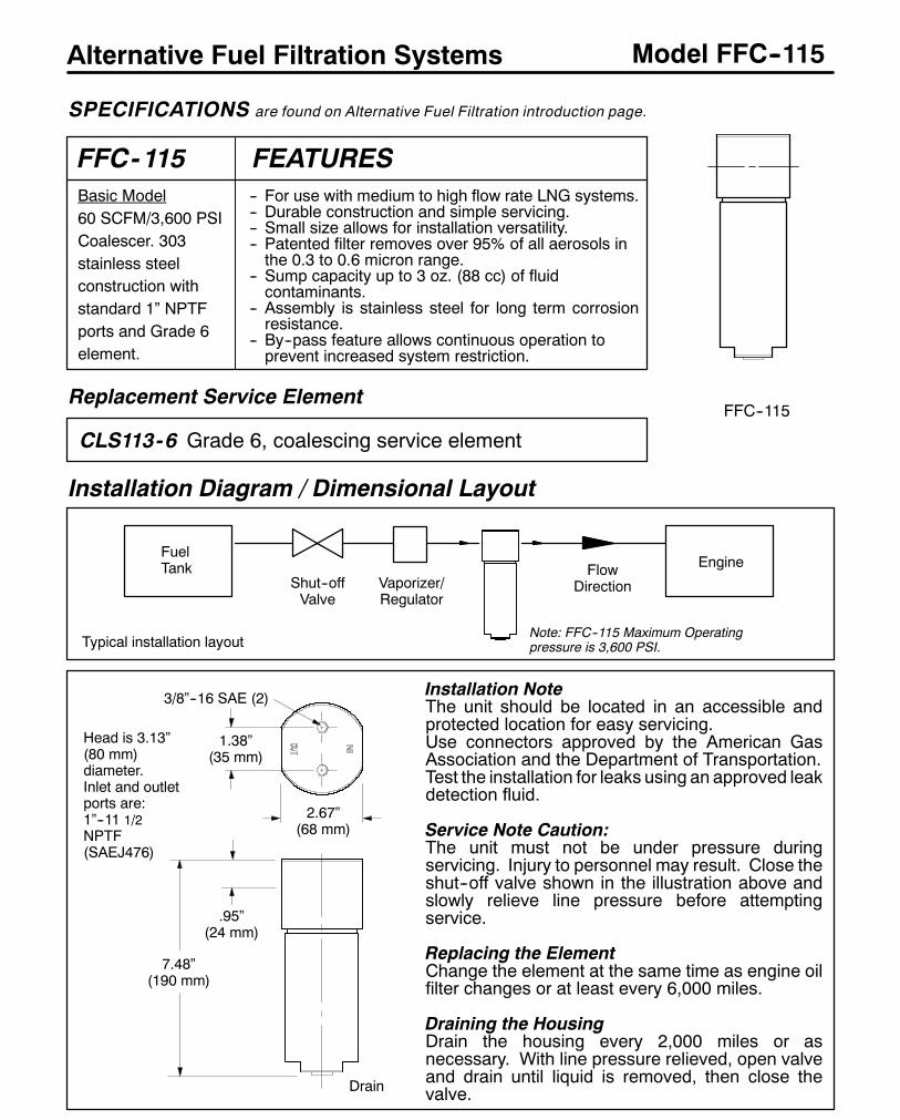
238
Alternative Fuel Filtration Systems Model FFC--115
SPECIFICATIONS are found on Alternative Fuel Filtration introduction page.
Replacement Service ElementFFC--115
FFC-115Basic Model60 SCFM/3,600 PSICoalescer. 303stainless steelconstruction withstandard 1” NPTFports and Grade 6element.
FEATURES-- For use with medium to high flow rate LNG systems.-- Durable construction and simple servicing.-- Small size allows for installation versatility.-- Patented filter removes over 95% of all aerosols inthe 0.3 to 0.6 micron range.
-- Sump capacity up to 3 oz. (88 cc) of fluidcontaminants.
-- Assembly is stainless steel for long term corrosionresistance.
-- By--pass feature allows continuous operation toprevent increased system restriction.
Installation Diagram / Dimensional Layout
CLS113-6 Grade 6, coalescing service element
Head is 3.13”(80 mm)diameter.Inlet and outletports are:1”--11 1/2NPTF(SAEJ476)
Drain
EngineFuelTank
Shut--offValve
FlowDirection
Installation NoteThe unit should be located in an accessible andprotected location for easy servicing.Use connectors approved by the American GasAssociation and the Department of Transportation.Test the installation for leaks using an approved leakdetection fluid.
Service Note Caution:The unit must not be under pressure duringservicing. Injury to personnel may result. Close theshut--off valve shown in the illustration above andslowly relieve line pressure before attemptingservice.
Replacing the ElementChange the element at the same time as engine oilfilter changes or at least every 6,000 miles.
Draining the HousingDrain the housing every 2,000 miles or asnecessary. With line pressure relieved, open valveand drain until liquid is removed, then close thevalve.
3/8”--16 SAE (2)
1.38”(35 mm)
7.48”(190 mm)
2.67”(68 mm)
.95”(24 mm)
Typical installation layoutNote: FFC--115 Maximum Operatingpressure is 3,600 PSI.
Vaporizer/Regulator
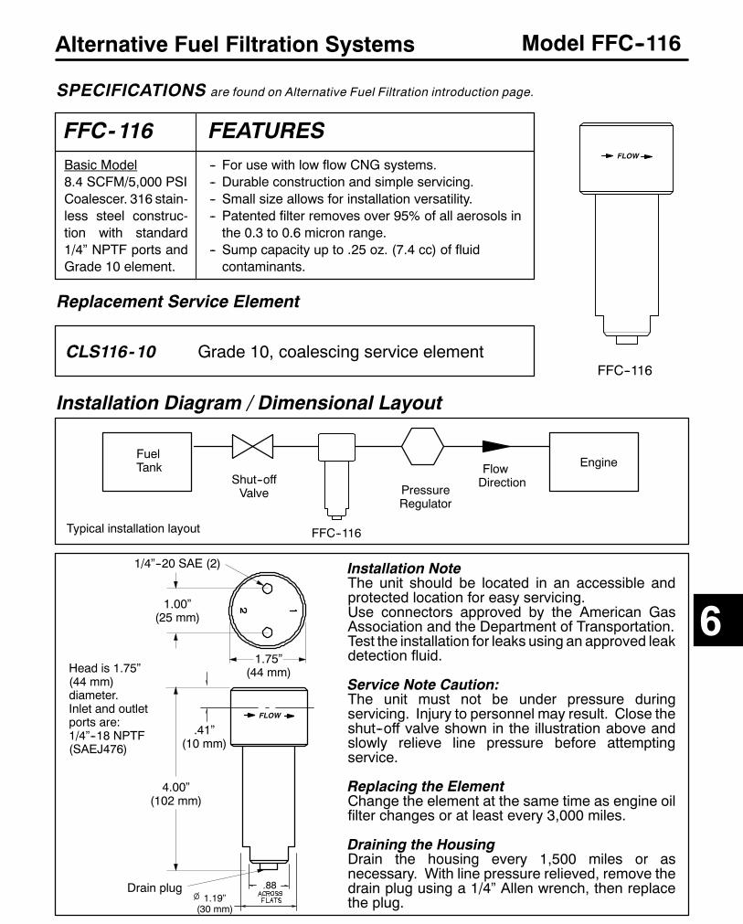
239
Alternative Fuel Filtration Systems Model FFC--116
SPECIFICATIONS are found on Alternative Fuel Filtration introduction page.
Replacement Service Element
FFC--116
FFC-116Basic Model8.4 SCFM/5,000 PSICoalescer. 316 stain-less steel construc-tion with standard1/4” NPTF ports andGrade 10 element.
FEATURES-- For use with low flow CNG systems.-- Durable construction and simple servicing.-- Small size allows for installation versatility.-- Patented filter removes over 95% of all aerosols inthe 0.3 to 0.6 micron range.
-- Sump capacity up to .25 oz. (7.4 cc) of fluidcontaminants.
Installation Diagram / Dimensional Layout
4.00”(102 mm)
FLOW
CLS116-10 Grade 10, coalescing service element
FLOW
Head is 1.75”(44 mm)diameter.Inlet and outletports are:1/4”--18 NPTF(SAEJ476)
Drain plug
1.75”(44 mm)
EngineFuelTank
Shut--offValve Pressure
Regulator
FlowDirection
Installation NoteThe unit should be located in an accessible andprotected location for easy servicing.Use connectors approved by the American GasAssociation and the Department of Transportation.Test the installation for leaks using an approved leakdetection fluid.
Service Note Caution:The unit must not be under pressure duringservicing. Injury to personnel may result. Close theshut--off valve shown in the illustration above andslowly relieve line pressure before attemptingservice.
Replacing the ElementChange the element at the same time as engine oilfilter changes or at least every 3,000 miles.
Draining the HousingDrain the housing every 1,500 miles or asnecessary. With line pressure relieved, remove thedrain plug using a 1/4” Allen wrench, then replacethe plug.
1/4”--20 SAE (2)
1.00”(25 mm)
Typical installation layout FFC--116
.41”(10 mm)
.881.19”
(30 mm)
6
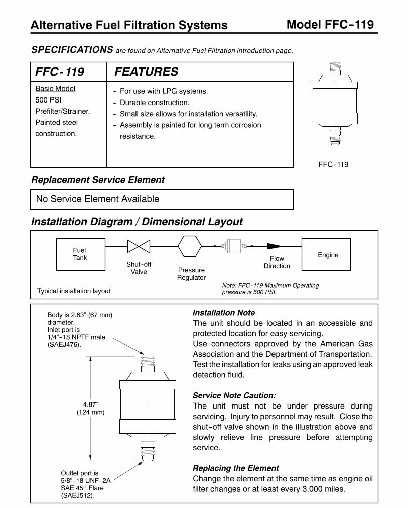
240
Alternative Fuel Filtration Systems Model FFC--119
SPECIFICATIONS are found on Alternative Fuel Filtration introduction page.
Replacement Service Element
FFC--119
FFC-119Basic Model
500 PSIPrefilter/Strainer.Painted steel
construction.
FEATURES-- For use with LPG systems.
-- Durable construction.-- Small size allows for installation versatility.-- Assembly is painted for long term corrosion
resistance.
Installation Diagram / Dimensional Layout
Body is 2.63” (67 mm)diameter.Inlet port is1/4”--18 NPTF male(SAEJ476).
EngineFuelTank
Shut--offValve Pressure
Regulator
FlowDirection
Installation NoteThe unit should be located in an accessible andprotected location for easy servicing.Use connectors approved by the American GasAssociation and the Department of Transportation.Test the installation for leaks using an approved leakdetection fluid.
Service Note Caution:The unit must not be under pressure duringservicing. Injury to personnel may result. Close theshut--off valve shown in the illustration above andslowly relieve line pressure before attemptingservice.
Replacing the ElementChange the element at the same time as engine oilfilter changes or at least every 3,000 miles.
Typical installation layoutNote: FFC--119 Maximum Operatingpressure is 500 PSI.
Outlet port is5/8”--18 UNF--2ASAE 45_ Flare(SAEJ512).
4.87”(124 mm)
No Service Element Available

Racor Products Section 7 Crankcase Ventilation Systems
Global FiltrationTechnology
Help & General Information
?
Selection
CV Products
CV820
CV1000
CCV Products
CCV4500
CCV6000
CCV8000
Accessories
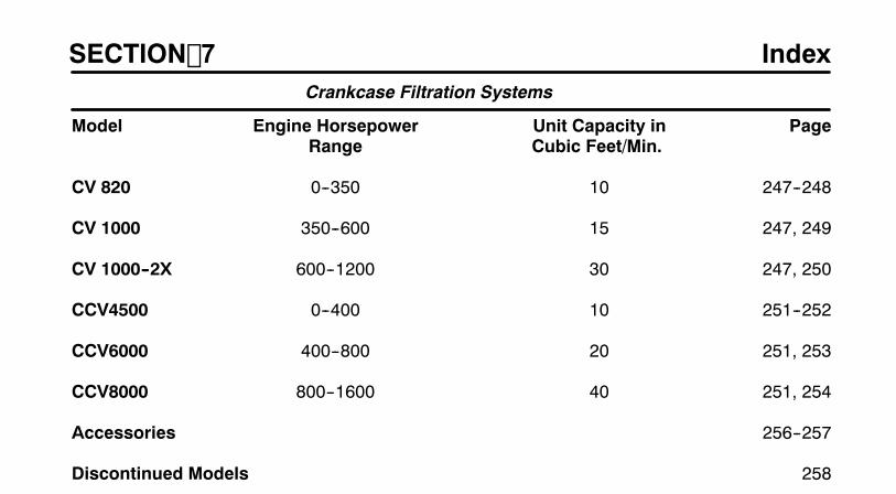
245
SECTION 7
Model Engine Horsepower Unit Capacity in PageRange Cubic Feet/Min.
CV 820 0--350 10 247--248
CV 1000 350--600 15 247, 249
CV 1000--2X 600--1200 30 247, 250
CCV4500 0--400 10 251--252
CCV6000 400--800 20 251, 253
CCV8000 800--1600 40 251, 254
Accessories 256--257
Discontinued Models 258
IndexCrankcase Filtration Systems
GeneralRacor Crankcase Filtration Systems offer an effective means to eliminate contaminated crankcaseemissions. These emissions not only pollute the air and the engine room, they contribute toincreased maintenance costs.Crankcase emissions are a result of high pressure ’blow--by’ around piston rings which eitherescapes into the engine compartment or is ingested back into the engine in closedsystems. Escapedemissions, an oily mist, can accumulate on engine components, compartment surfaces andequipment creating not only increased cleanup but a potential for safety hazards (slipperywalkways)and fuel for potential fires. Emissions can also contribute to increased engine maintenance costsas oily residues build up on critical components such as radiator cores, turbocharger blades,intercoolers and air filters. These residues act as a ’magnet’ for dust, grit and other airbornecontaminants resulting in an accumulation in unacceptable contamination.
Crankcase Filtration Systems utilizes high--efficiency filter media to recycle and remove 70% to 80%of emissions at 0.3 microns and 90% of emissions at 1.0 microns in size. In closed systems, NOxand hydrocarbon emissions are reduced by lowering combustion temperatures. Remaining gasesand vapors are safely returned to the engine’s combustion inlet. Oil that is separated by the mediais collected in the removable sump or drained to the oil pan for easy servicing.
1. DETERMINE THE MAXIMUM HORSEPOWER RATING OF THE ENGINE.
2. DETERMINE WHERE THE UNIT WILL BE MOUNTED. IF SIZE IS A LIMITING FACTOR,CHECK SPECIFICATIONS ON NEXT PAGE FOR UNIT DIMENSIONS.
Using this information, select a unit for service from above which meets or exceeds theengine horsepower and fits within installation size limitations (if any).
Selection
7

247
CV Crankcase Filtration Systems
Specifications
BASIC MODELS CV820 CV1000
Engine Horsepower HP 0--350 350--600Rating, Max. KW 0--260 260--450
Inlet Port Size 1” NPT 1 1/4” NPTOulet Port Size 1” NPT 1 1/4” NPT
Max. Air Flow* CFM 10 15L/s 4.72 7.08
Filter Element CV820SK CV1000SK
Height in. 7.55 8.48mm 192 215
Diameter (depth) in. 6.00 8.14mm 152 207
Weight (dry) Lbs. 2.0 3.0kgs. 0.9 1.4
Sump Capacity: fl. oz. 32 58ml. 946 1720
Operating Temperature --40o / +255o F / --40o / +121o C
* Values given are cubic feet per minute (CFM) and liters per second (L/s).1. For horsepower rating consult your engine manual, engine manufacturer’s agent or a Racor distributor.
Model Illustrations
Special Notes
1. For additional information and availability, contact customer service at: (800) 344--3286, 6 AM to 5 PM, Pacific Time.2. CV units are for Open System applications only.
CV820
7
Introduction
CV1000
CV Style for Open Systems

248
CV Crankcase Filtration Systems Model CV820
SPECIFICATIONS are found on Emission Control Systems introduction page.
Replacement Service Element
CV820Basic Model
For 0--350Horsepowerrated engines.
Unit flow capacity is10 CFM.
FEATURES-- For use with open systems only.
-- Durable construction.-- Compact size allows for installation versatility.-- Replaceable filter media.
-- Removable oil collection sump.Assembly is black anodized for long term corrosion
resistance.
Installation Diagram / Dimensional Layout
CV820SK Service element, includes housing gasket
Body is 6.00” (152 mm)diameter.Either port may be Inlet /outlet:1”--11 1/2 NPT female(SAEJ476).
Service:On units that do not return the oil to the crankcase, check ordrain the sump frequently until a routine service interval isestablished.
Replacing the Element:Change the element every 500 hours or every oil change.Follow instructions supplied with the unit.
Replacement Parts List:Part No. Description Qty.CV820--02 Filter Bottom Assembly 1CV820--09 Mounting Bracket, Stainless Steel 1Optional Parts List:CV7019 90_ Exhaust Elbow (see open system) 1
For parts not listed, call Racor customer service:(800) 344--3286, 6 AM to 5 PM, Pacific Time.
CV820
TypicalOpenSysteminstallation.No scale.
Engine
Draft tubeAir
Cleaner
CV820
Toatmosphere
3.35”(85 mm)
.33” (8 mm)clearancerequired forfasteners.
Quick releaseclamps retaincollectionsump.
Drain valve
Top View
(CV7019)
Oil level

249
CV Crankcase Filtration Systems Model CV1000
SPECIFICATIONS are found on Emission Control Systems introduction page.
Replacement Service Element
CV1000Basic Model
For 350--600Horsepowerrated engines.
Unit flow capacity is15 CFM.
FEATURES-- For use with open systems only.
-- Adjustable body strap bracket.-- Durable design and construction.-- Replaceable filter media.
-- Removable oil collection sump.Assembly is black anodized for long term corrosion
resistance.
Installation Diagram / Dimensional Layout
CV1000SK Service element. Order housing gasket below.
Body is 8.14” (207 mm)diameter.Either port may be Inlet /outlet:1 1/4”--11 1/2 NPT female(SAEJ476).
Service:On units that do not return the oil to the crankcase, check ordrain the sump frequently until a routine service interval isestablished.
Replacing the Element:Change the element every 500 hours or every oil change.Follow instructions supplied with the unit.
Replacement Parts List:Part No. Description Qty.CV1000--02 Filter Bottom Assembly 1CV1000--04 Housing Gasket 1CV1000--09 Mounting Bracket, Stainless Steel 1Optional Parts List:CV7018 90_ Exhaust Elbow 1
For parts not listed, call Racor customer service:(800) 344--3286, 6 AM to 5 PM, Pacific Time.
7
CV1000
TypicalOpenSysteminstallation.No scale.
Engine
Draft tubeAir
Cleaner
CV1000
Toatmosphere
3.35”(85 mm)
.33” (8 mm)clearancerequired forfasteners.
Quick releaseclamps retaincollectionsump.
Drain valve
Top View
(CV7018)
Oil level

251
CCVt Crankcase Filtration Systems
Specifications
BASIC MODELS CCV4500 CCV6000 CCV8000
Engine Horsepower HP 0--400 400--800 800--1600Rating, Max. KW 0--298 298--597 597--1,193
Inlet/Outlet Port Size 1 3/16”--12 SAE 1 5/8”--12 SAE 1 7/8”--12 SAE
Max. Air Flow* CFM 10 20 40L/s 4.72 9.44 18.88
Filter Element CCV55248--06 CCV55274--06 CCV55222--06CCV55248--08 CCV55274--08 CCV55222--08
Height in. 9.25 12.00 13.88mm 235.0 304.8 352.6
Diameter (depth) in. 5.60 7.30 9.30mm 142.2 185.4 236.2
Width in. 7.16 8.59 10.61mm 181.9 218.2 269.5
Weight (dry) Lbs. 3.26 5.01 8.72kgs. 1.48 2.28 3.96
Operating Temperature --40o / +240o F / --40o / +116o C
* Values given are cubic feet per minute (CFM) and liters per second (L/s).1. For horsepower rating consult your engine manual, engine manufacturer’s agent or a Racor distributor.
Model Illustrations
Special Notes
1. For additional information and availability, contact customer service at: (800) 344--3286, 6 AM to 5 PM, Pacific Time.2.All CCV units are for Closed System applications only.
7
Introduction
CCV4500CCV6000 CCV8000
CCV Style for Closed Systems
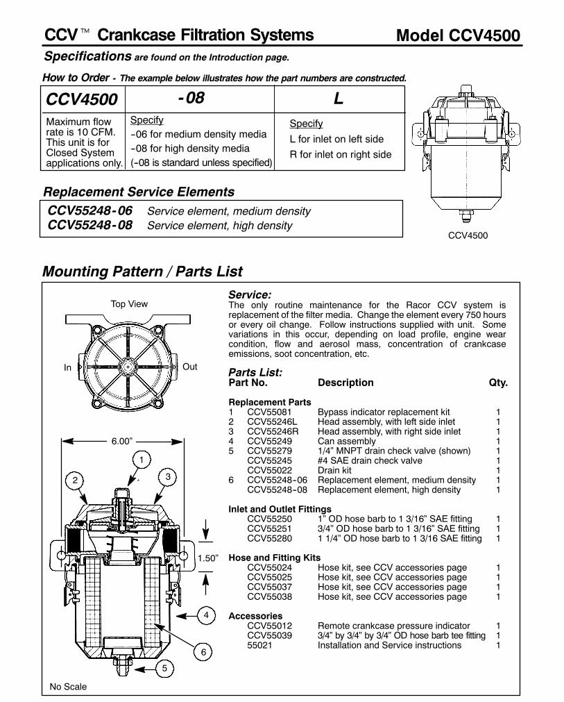
252
Model CCV4500
Replacement Service Elements
CCV4500Maximum flowrate is 10 CFM.This unit is forClosed Systemapplications only.
Mounting Pattern / Parts List
CCV55248-06 Service element, medium densityCCV55248-08 Service element, high density
Service:The only routine maintenance for the Racor CCV system isreplacement of the filter media. Change the element every 750 hoursor every oil change. Follow instructions supplied with unit. Somevariations in this occur, depending on load profile, engine wearcondition, flow and aerosol mass, concentration of crankcaseemissions, soot concentration, etc.
Parts List:Part No. Description Qty.
Replacement Parts1 CCV55081 Bypass indicator replacement kit 12 CCV55246L Head assembly, with left side inlet 13 CCV55246R Head assembly, with right side inlet 14 CCV55249 Can assembly 15 CCV55279 1/4” MNPT drain check valve (shown) 1
CCV55245 #4 SAE drain check valve 1CCV55022 Drain kit 1
6 CCV55248--06 Replacement element, medium density 1CCV55248--08 Replacement element, high density 1
Inlet and Outlet FittingsCCV55250 1” OD hose barb to 1 3/16” SAE fitting 1CCV55251 3/4” OD hose barb to 1 3/16” SAE fitting 1CCV55280 1 1/4” OD hose barb to 1 3/16 SAE fitting 1
Hose and Fitting KitsCCV55024 Hose kit, see CCV accessories page 1CCV55025 Hose kit, see CCV accessories page 1CCV55037 Hose kit, see CCV accessories page 1CCV55038 Hose kit, see CCV accessories page 1
AccessoriesCCV55012 Remote crankcase pressure indicator 1CCV55039 3/4” by 3/4” by 3/4” OD hose barb tee fitting 155021 Installation and Service instructions 1
Top View
- 08 LSpecify--06 for medium density media--08 for high density media(--08 is standard unless specified)
Specify
L for inlet on left sideR for inlet on right side
CCV4500
How to Order - The example below illustrates how the part numbers are constructed.
In Out
No Scale
1
2 3
4
6
5
1.50”
6.00”
Specifications are found on the Introduction page.
CCVt Crankcase Filtration Systems

253
Model CCV6000SPECIFICATIONS are found on Introduction page.
Replacement Service Element
7
CCV6000
Top View
CCV55274-06 Service element, medium densityCCV55274-08 Service element, high density
How to Order - The example below illustrates how the part numbers are constructed.
Mounting Pattern / Parts List
In Out
0.93”
7.50”
No Scale
3
4
5
6
21
CCV6000Maximum flowrate is 20 CFM.This unit is forClosed Systemapplications only.
- 08 LSpecify--06 for medium density media--08 for high density media(--08 is standard unless specified)
Specify
L for inlet on left sideR for inlet on right side
Service:The only routine maintenance for the Racor CCV system isreplacement of the filter media. Change the element every 750 hoursor every oil change. Follow instructions supplied with unit. Somevariations in this occur, depending on load profile, engine wearcondition, flow and aerosol mass, concentration of crankcaseemissions, soot concentration, etc.
Parts List:Part No. Description Qty.
Replacement Parts1 CCV55081 Bypass indicator replacement kit 12 CCV55272L Head assembly, left side inlet 13 CCV55272R Head assembly, right side inlet 14 CCV55275 Can assembly 15 CCV55279 1/4” MNPT drain check valve (shown) 1
CCV55245 #4 SAE drain check valve 1CCV55022 Drain kit 1
6 CCV55274--06 Replacement element, medium density 1CCV55274--08 Replacement element, high density 1
Inlet and Outlet FittingsCCV55267 1 1/2” OD hose barb to 1 5/8” SAE fitting 1CCV55268 1 1/4” OD hose barb to 1 5/8” SAE fitting 1
Hose and Fitting KitsCCV55046 Hose kit, see CCV accessories page 1CCV55047 Hose kit, see CCV accessories page 1CCV55048 Hose kit, see CCV accessories page 1CCV55049 Hose kit, see CCV accessories page 1
AccessoriesCCV55012 Remote crankcase pressure indicator 1CCV55040 1 1/4” by 1 1/4” by 1 1/4” OD hose barb
tee fitting 1CCV55020 1 1/2” by 1 1/4” Bushing Reducer 155021 Installation and Service instructions
CCVt Crankcase Filtration Systems

Model CCV8000SPECIFICATIONS are found on Introduction page.
Replacement Service Element
CCV8000
CCVt Crankcase Filtration Systems
CCV8000Maximum flowrate is 40 CFM.This unit is forClosed Systemapplications only.
- 08 LSpecify--06 for medium density media--08 for high density media(--08 is standard unless specified)
Specify
L for inlet on left sideR for inlet on right side
CCV55222-06 Service element, medium densityCCV55222-08 Service element, high density
Service:The only routine maintenance for the Racor CCV system is replacementof the filter media. Change the element every 750 hours or every oilchange. Follow instructions supplied with unit. Some variations in thisoccur, depending on load profile, enginewear condition, flow andaerosolmass, concentration of crankcase emissions, soot concentration, etc.
Parts List:Part No. Description Qty.
Replacement Parts1 CCV55081 Bypass indicator replacement kit 12 CCV55220L Head assembly, left side inlet 13 CCV55220R Head assembly, right side inlet 14 CCV55223 Can assembly 15 CCV55080 3/8” MNPT drain check valve (shown) 1
CCV55288 #8 SAE drain check valve 1CCV55071 Drain kit 1
6 CCV55222--06 Replacement element, medium density 1CCV55222--08 Replacement element, high density 1
Inlet and Outlet FittingsCCV55218 1 1/2” OD hose barb to 1 7/8” SAE fitting 1
Hose and Fitting KitsCCV55067 Hose kit, see CCV accessories page 1CCV55068 Hose kit, see CCV accessories page 1CCV55069 Hose kit, see CCV accessories page 1
AccessoriesCCV55012 Remote crankcase pressure indicator 1CCV55041 1 1/2” by 1 1/2” by 1 1/2” OD hose barb
tee fitting 1CCV55020 1 1/2” by 1 1/4” Bushing Reducer 155021 Installation and Service instructions
How to Order - The example below illustrates how the part numbers are constructed.
1.06”
9.50”
Top View
In Out
No Scale
3
4
5
6
21
Mounting Pattern / Parts List
254

256
Crankventt Filtration Systems Accessories
Hose Kits(for models CV820 and CV1000 only)
Part No. DescriptionCV1034 5 feet of 3/4” hose, fittings, clamps and tiesCV2034 7 1/2 feet of 3/4” hose, 3/4” Tee fitting, fittings, clamps and tiesCV1100 5 feet of 1” hose, fittings, clamps and tiesCV1114 5 feet of 1 1/4” hose, fittings, clamps and tiesCV2114 7 1/2 feet of 1 1/4” hose, 1 1/4” Tee fitting, fitting, clamps and tiesCV1112 5 feet of 1 1/2” hose, fitting, clamps and tiesCV1200 5 feet of 1 1/2” hose with 2” cuff, fitting, clamps and tiesCV1038 Air Box Drain Hose Kit, 8 feet of 3/8” hose, check valve, fittings, clamps & ties
Open System Exhaust ElbowsPart No. DescriptionCV7022 1 1/4” 90 degree elbow for CV400 filter outlet and clampCV7019 1 1/2” 90 degree elbow for CV820 filter outlet and clampCV7018 2” 90 degree elbow for CV1000 filter outlet and clamp
Closed System PartsPart No. DescriptionCV6022 3/4” barbed fitting assembly for the dirty side of the air filterCV6024 1” barbed fitting assembly for the dirty side of the air filterCV6025 1 1/4” barbed fitting assembly for the dirty side of the air filterCV8021 1” Pressure regulator
Closed System Kits -Dirty SidePart No. DescriptionCV6022CS CV6022 fitting, 5 feet of 3/4” hose, fittings, clamps and tiesCV6024CS CV6024 fitting, 5 feet of 1” hose, fittings, clamps and tiesCV6025CS CV6025 fitting, 5 feet of 1 1/4” hose, fittings, clamps and ties
Closed System Kits -Clean SideCV8021CS CV8021 pressure regulator, 5 feet of 1” hose, clamps and ties
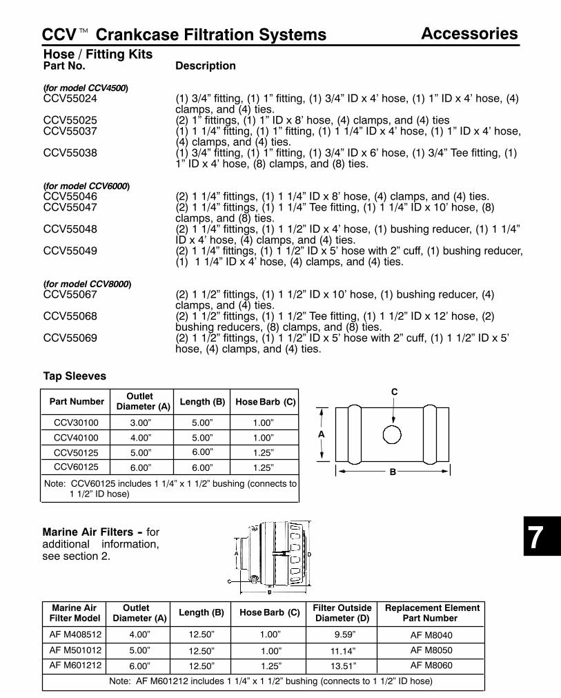
257
CCVt Crankcase Filtration Systems AccessoriesHose / Fitting KitsPart No. Description
(for model CCV4500)CCV55024 (1) 3/4” fitting, (1) 1” fitting, (1) 3/4” ID x 4’ hose, (1) 1” ID x 4’ hose, (4)
clamps, and (4) ties.CCV55025 (2) 1” fittings, (1) 1” ID x 8’ hose, (4) clamps, and (4) tiesCCV55037 (1) 1 1/4” fitting, (1) 1” fitting, (1) 1 1/4” ID x 4’ hose, (1) 1” ID x 4’ hose,
(4) clamps, and (4) ties.CCV55038 (1) 3/4” fitting, (1) 1” fitting, (1) 3/4” ID x 6’ hose, (1) 3/4” Tee fitting, (1)
1” ID x 4’ hose, (8) clamps, and (8) ties.
(for model CCV6000)CCV55046 (2) 1 1/4” fittings, (1) 1 1/4” ID x 8’ hose, (4) clamps, and (4) ties.CCV55047 (2) 1 1/4” fittings, (1) 1 1/4” Tee fitting, (1) 1 1/4” ID x 10’ hose, (8)
clamps, and (8) ties.CCV55048 (2) 1 1/4” fittings, (1) 1 1/2” ID x 4’ hose, (1) bushing reducer, (1) 1 1/4”
ID x 4’ hose, (4) clamps, and (4) ties.CCV55049 (2) 1 1/4” fittings, (1) 1 1/2” ID x 5’ hose with 2” cuff, (1) bushing reducer,
(1) 1 1/4” ID x 4’ hose, (4) clamps, and (4) ties.
(for model CCV8000)CCV55067 (2) 1 1/2” fittings, (1) 1 1/2” ID x 10’ hose, (1) bushing reducer, (4)
clamps, and (4) ties.CCV55068 (2) 1 1/2” fittings, (1) 1 1/2” Tee fitting, (1) 1 1/2” ID x 12’ hose, (2)
bushing reducers, (8) clamps, and (8) ties.CCV55069 (2) 1 1/2” fittings, (1) 1 1/2” ID x 5’ hose with 2” cuff, (1) 1 1/2” ID x 5’
hose, (4) clamps, and (4) ties.
7
Part Number OutletDiameter (A) Length (B) HoseBarb (C)
CCV30100
CCV40100
CCV50125
CCV60125
3.00”
4.00”
5.00”
6.00”
5.00”
5.00”
6.00”
6.00”
1.00”
1.00”
1.25”
1.25”
Note: CCV60125 includes 1 1/4” x 1 1/2” bushing (connects to1 1/2” ID hose)
A
B
C
Tap Sleeves
Marine AirFilter Model
AF M408512
AF M501012
AF M601212
OutletDiameter (A)
Length (B) HoseBarb (C) Filter OutsideDiameter (D)
Note: AF M601212 includes 1 1/4” x 1 1/2” bushing (connects to 1 1/2” ID hose)
4.00”
5.00”
6.00”
12.50”
12.50”
12.50”
1.00”
1.00”
1.25” 13.51”
11.14”
9.59”
Replacement ElementPart Number
AF M8040
AF M8050
AF M8060
Marine Air Filters -- foradditional information,see section 2.

Racor Products Section 8 Air Filters
Global FiltrationTechnology
Help & General Information
?
Introduction
On-Highway
Transit Filters
Replacement Marine Air Filters
Accessories

264
SECTION 8
Selection Information
GeneralRacor Long Life Air Filters feature a multi--stage, depth media treated with a specially formulated compound.Long Life filters are not cleanable and can still:D Hold up to 8 times more contaminants than conventional paper filters.D Provide a minimum of twice the service life of conventional paper filters.D Increase fuel economy due to lower initial restriction.D Prevent corrosion by repelling water.
Twice--the--life GuaranteeParker Hannifin Corporation, Racor Division guarantees that each new Long Life Air Filter Element will provide aminimum of Twice--The--Life service compared to a conventional pleated paper--type air filter element, if it is installedproperly and serviced according to the manufacturer’s recommended procedures.
If any Long Life Air Filter element fails to provide at least Twice--The--Life service of the conventional pleated paper--typeair filter element that the user has been using, Racor will replace the air filter, free of charge. (See Accessories sectionfor details).
When to Change the Long Life FilterThe only reliable way to tell when the filter is ’used up’ is to measure the restriction. An inexpensive restriction gauge,provides a reliable restriction reading at all times.
A word about exhaust smoking. There should be little, if any, significant smoke, black or white coming from the exhaustpipe of a properly warmed engine. A lot of white smoke means that there is excess, unburned fuel being pushed throughthe system. Black smoke indicates incomplete combustion, typically from a restricted air intake. Check for air cleanerand related component blockages.
Superior PerformanceThe condensed report below presents results conducted in accordancewith the SAEJ726 JUN87Air Cleaner TestCode.The results provide airflow pressure drop, efficiency and dust holding capacity using a Long Life, N0387 air filter elementinstalled in a P15--0862 housing. Clean element pressure drop and restriction, initial, incremental and cumulativeefficiency, and dust holding capacity were measured. The efficiency/dust holding capacity test was conducted at 1100SCFM (25_C, 100 kPa) using AC FINE Test Dust at a concentration of 0.25 g/m3 air (0.007 g/ft3 air).
The test was conducted by Southwest Research Institute, an independent scientific laboratory. All of the data belowexcept for the far right column is an excerpt from the Southwest Research Institute test results.
SELECTIONRefer to the Index page for your equipment classification and applicable cross reference table.
For additional information, call your Racor dealer or call Racor customer service at (209) 521--7860 or (800)344--3286, 6:00 AM to 5:00 PM, Pacific Time, or e--mail us from our website www.parker.com/racor.
Introduction
Dust Holding Pressure 0.5 Micron 5 Micron 10 Micron ≥15 Micron Average AverageCapacity Drop, (in. % Efficient % Efficient % Efficient % Efficient % Efficient % Efficient(grams) H2O)
8 5.2 99.82 93.50 99.87 100 97.36 99.20111 5.8 99.55 97.98 99.87 100 99.15 99.73228 6.6 99.66 98.67 99.66 99.98 99.36 99.77413 8.3 99.94 99.98 99.94 99.98 99.97 99.97530 9.9 99.99 99.92 99.96 100 99.96 99.98614 12.3 99.40 99.95 99.96 100 99.97 99.99756 18.5 99.90 99.90 99.96 99.96 99.94 99.95805 23.8 99.98 99.92 99.66 100 99.87 99.98
Dust Type Fine Fine Fine Fine Fine Coarse
AC FINE Test Dust was used in the actual test because it represents the most rigorous conditions. The far right columnis extrapolated data weighted for AC COARSE Test Dust which is more representative of ’over--the--road’ conditions.
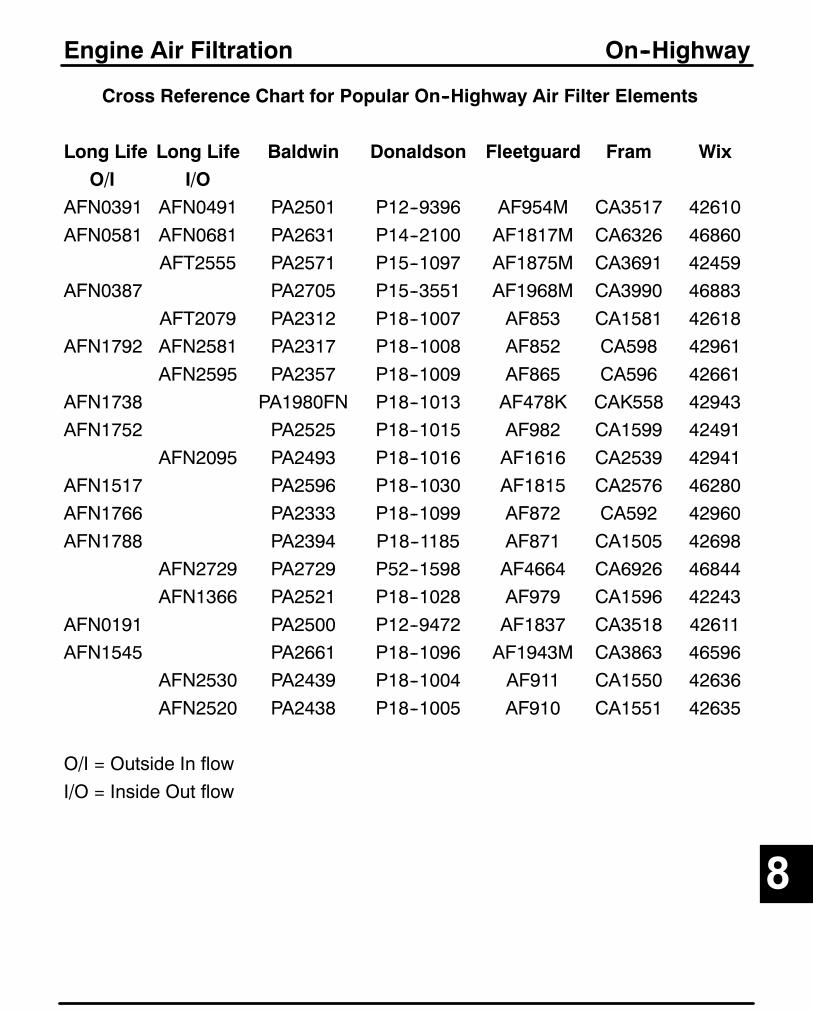
265
Cross Reference Chart for Popular On--Highway Air Filter Elements
Long Life Long Life Baldwin Donaldson Fleetguard Fram WixO/I I/O
AFN0391 AFN0491 PA2501 P12--9396 AF954M CA3517 42610AFN0581 AFN0681 PA2631 P14--2100 AF1817M CA6326 46860
AFT2555 PA2571 P15--1097 AF1875M CA3691 42459AFN0387 PA2705 P15--3551 AF1968M CA3990 46883
AFT2079 PA2312 P18--1007 AF853 CA1581 42618AFN1792 AFN2581 PA2317 P18--1008 AF852 CA598 42961
AFN2595 PA2357 P18--1009 AF865 CA596 42661AFN1738 PA1980FN P18--1013 AF478K CAK558 42943AFN1752 PA2525 P18--1015 AF982 CA1599 42491
AFN2095 PA2493 P18--1016 AF1616 CA2539 42941AFN1517 PA2596 P18--1030 AF1815 CA2576 46280AFN1766 PA2333 P18--1099 AF872 CA592 42960AFN1788 PA2394 P18--1185 AF871 CA1505 42698
AFN2729 PA2729 P52--1598 AF4664 CA6926 46844AFN1366 PA2521 P18--1028 AF979 CA1596 42243
AFN0191 PA2500 P12--9472 AF1837 CA3518 42611AFN1545 PA2661 P18--1096 AF1943M CA3863 46596
AFN2530 PA2439 P18--1004 AF911 CA1550 42636AFN2520 PA2438 P18--1005 AF910 CA1551 42635
O/I = Outside In flowI/O = Inside Out flow
Engine Air Filtration On--Highway
8

266
Cross Reference Chart for Popular Transit use Air Filter Elements
Long Life Long Life AC Air Baldwin Donaldson FleetgrdO/I I/O Refiner
PC185AFT9029 A1035C ARM2301 PA2474 P15--1951 AF1798
AFT1766 A1081C ARM11--8047 PA2333 P18--1099 AF872
AFS2595AFT2595 A579C ARM11--6880 PA2357 P18--1009 AF865
A726CAFT1379 AFT2079 A590C ARM11--7797 PA2312 P18--1007 AF853
AFT1780 AFT2780 A774C ARM12--4490 PA2515 P15--3973 AF995M
AFT2555 A850C ARM13--3754 PA2571 P15--1098 AF4782
AFT2760 ARM15--3972 PA3573 P15--3972 AF4784
AFT1850 ARM52--2874 PA2839 P77--1582 AF1812
AFT1778 ARM11--8039 PA2394 P18--1185 AF871
O/I = Outside In flowI/O = Inside Out flow
Engine Air Filtration Transit Filters

267
Replacement Filters for Marine Air Filter/Silencer Will--Fit Elements
Racor now offers replacement filters for AirSep type marine applications. These filters are directreplacements for the intake air filter portion of competitive air filters/silencers. Also available is thereplacement element for the Vacuum Limiter Air Separator.The filter media for all replacement filters is an oil--impregnated cotton gauze and is sandwiched betweenpleated, epoxy--coated aluminum wire--mesh with molded polyurethane sealing surfaces. This product iscleanable and must be oiled before re--using.
Engine Air Filtration Washable Replacement Filters
8d
D
H
D
H
AF M81xx Series AF M80xx Series
d
Walker Part Number Racor Part Number Dimensions (in inches)(D x H x d)
CD169 N/A 16 x 16 x 16CD170 AF M8145 10 x 8 x 10CD173 N/A 7.5 x 5 x 7.5CD174 AF M8121 7.5 x 6 x 7.5CD175 AF M8122 7.5 x 7 x 7.5CD176 N/A 7.5 x 8 x 7.5CD177 AF M8124 7.5 x 9 x 7.5CD178 AF M8126 7.5 x 10 x 7.5CD180 AF M8010 3” Air Separator ElementCD181 AF M8146 10 x 10 x 10CD182 AF M8143 10 x 12 x 10CD183 AF M8153 12 x 12 x 12CD184 AF M8037 9 x 14 x 6.875CD185 N/A 10 x 14CD186 AF M8152 12 x 7 x 12CD187 AF M8155 12 x 8 x 12CD189 N/A 12 x 14 x 12CD190 AF M8026 7.5 x 10 x 5.125CD194 AF M8021 7.5 x 6 x 5.125CD195 AF M8025 7.5 x 8 x 5.125CD196 AF M8034 9 x 9CD197 AF M8033 9 x 12CD200 AF M8134 9 x 9 x 9CD201 AF M8133 9 x 12 x 9CD202 AF M8141 10 x 6 x 10CD203 AF M8151 12 x 6 x 12CD204 AF M8156 12 x 10 x 12
Detroit Diesel PN.23508033 AF M8033 12” Filter23508034 AF M8034 9” Filter

268
When should you change your Long Life filter?
Long Life filters do a great job of stopping dirt, soot and water before they can contaminant your engines. Such a great
job that a filter that has been in use for awhile will look very dirty like it is already clogged. But that just means it is doing
its job. Remember that every filter change is an opportunity to contaminant your engine, so unnecessary changes
should be avoided. The only way to tell when the filter is ’used up’ is tomeasure the restriction. Your shop has equipment
for precise measurement during service stops. An inexpensive restriction gauge, will give your drivers a restriction
reading your shop can verify when they get back in.
Engine Air Filtration Accessories
Part Number Scale/Description Case Qty.
AF H8500 20 in.H2O 1AF H8501 25 in.H2O 1AF H8502 30 in.H2O 1AF H8510 20 in.H2O, Dash Mount 1AF H8511 25 in.H2O, Dash Mount 1AF H8512 30 in.H2O, Dash Mount 1AF H8520 20 in.H2O, Electric 1AF H8521 25 in.H2O, Electric 1AF H8522 30 in.H2O, Electric 1AF H8530 20 in.H2O, Remote Mount 1AF H8531 25 in.H2O, Remote Mount 1AF H8532 30 in.H2O, Remote Mount 1
FILTERCHANGE
PUSH BUTTON TO RESET
AIR FILTER GAUGEIN H20
252215118
Air Service Restriction Indicator
DDCMarine Intake Silencer FoamWrapPart Number Quantity
AF M8001 6 per package
Foam cover improves filtration and further reducesnoise on Detroit Diesel style intake silencers
Racor Products Section 9 Additives
Global FiltrationTechnology
Help & General Information
?
Selection
Introduction
Conditioner Plus+
Biocide
Winter Plus+
Gasoline Conditioner +
Oil Treatment
Coolant Treatment

273
SECTION 9
Product Application Primary Use Page
Conditioner Plus+ Diesel Fuel Optimizes Performance 275--276
Biocide Diesel Fuel Kills Biological Growth 275, 277
Winter Plus+ Diesel Fuel Lowers Pour Point 275, 278
Conditioner Plus+ Gasoline Optimizes Performance 275, 279
Oil Treatment Lube Oil Reduces Friction 275, 280
Coolant Treatment Coolant Optimizes Performance 275, 281
IndexDiesel, Gasoline, Coolant and Lube Additives
GeneralThe all--new Racor additive line includes products for all climates and seasons. The products include abiocide: a year--’round conditioner and winter additive for diesel engines: a year--’round gasoline conditioner;lube oil treatment and coolant treatment. Racor additives mix well with fuels are not removed by fuel filters.
There are several convenient sizes: our 16 oz. bottle that makes measuring quick and easy, and 1 and 2.5gallon bottles are convenient for larger fuel tanks. The high concentration of active ingredients in Racoradditives allows for higher treatment rates.
Exhaust SmokeIn a properly warmed engine, there should be little, if any, significant smoke, black or white, coming from theexhaust pipe. Black smoke indicates incomplete combustion, typically from a dirty air filter, poor injection (aleaking or dribbling injector), engine overloading or the air intake temperature is too high (poor density).White smokemeans that there is excess, unburned fuel being pushed through the systemor that there iswateringestion (leaky gasket or crack in cylinder head or case).Blue smoke means the engine is burning crankcase oil. Causes can be worn valve guides/stems, broken orworn piston rings, a leak in the turbo or too much oil in the crankcase.
1. FOR OPTIMUM ENGINE PROTECTION AND EFFICIENCY, USE A FUEL AND OILCONDITIONER ALL THE TIME.
2. FOR OPERATIONS IN COLD CLIMATES WHERE DIESEL FUELS MAY GEL, USE DIESELWINTER PLUS+ WITH DIESEL CONDITIONER PLUS+.
3. FOROPERATIONS INHIGHHUMIDITYAREASORWHEREWATER INFUELTANKBOTTOMSIS EVER--PRESENT, USE DIESEL FUEL BIOCIDE WITH DIESEL CONDITIONER PLUS+.
4. FOR OPTIMUM COOLANT SYSTEM PROTECTION AND LUBRICATION, USE COOLANTTREATMENT.
Using this information, select a product from the following pages.
Selection
9
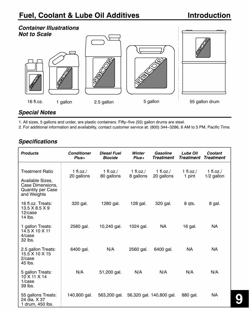
275
Fuel, Coolant & Lube Oil Additives
Specifications
Products Conditioner Diesel Fuel Winter Gasoline Lube Oil CoolantPlus+ Biocide Plus+ Treatment Treatment Treatment
Treatment Ratio 1 fl.oz./ 1 fl.oz./ 1 fl.oz./ 1 fl.oz./ 1 fl.oz./ 1 fl.oz./20 gallons 80 gallons 8 gallons 20 gallons 1 pint 1/2 gallon
Available Sizes,Case Dimensions,Quantity per Caseand Weights
16 fl.oz. Treats: 320 gal. 1280 gal. 128 gal. 320 gal. 8 qts. 8 gal.13.5 X 8.5 X 912/case14 lbs.
1 gallon Treats: 2560 gal. 10,240 gal. 1024 gal. NA 16 gal. NA14.5 X 10 X 114/case32 lbs.
2.5 gallon Treats: 6400 gal. N/A 2560 gal. 6400 gal. NA NA15.5 X 10 X 152/case45 lbs.
5 gallon Treats: N/A 51,200 gal. N/A N/A N/A N/A10 X 11 X 141/case39 lbs.
55 gallons Treats: 140,800 gal. 563,200 gal. 56,320 gal. 140,800 gal. 880 gal. NA24 dia. X 371 drum, 450 lbs.
Container IllustrationsNot to Scale
Special Notes
1. All sizes, 5 gallons and under, are plastic containers. Fifty--five (55) gallon drums are steel.2. For additional information and availability, contact customer service at: (800) 344--3286, 6 AM to 5 PM, Pacific Time.
Introduction
9
55 gallon drum2.5 gallon1 gallon16 fl.oz. 5 gallon

276
Fuel, Coolant & Lube Oil Additives Conditioner Plus+
Part Numbers / Sizes / Treatment
Part No. Size Treatment Case Qty.
ADT 1116 16 fl.oz. 320 gallons 12
ADT 1201 1 gallon 2560 gallons 4
ADT 1325 2.5 gallons 6,400 gallons 2
ADT 1555 55 gallons 140,800 gallons 1 drum
RK 21644 Pour spout extension (for 16 oz. bottle only) 1
Information about Racor Diesel Fuel Conditioner Plus+
During normal use, a diesel engine is subjected to a variety of loads under some of the most unusualconditions and in all types of weather. The performance of the engine is greatly determined by the qualityof fuel it burns. The best way for the operator to ensure that quality fuel is being used is to supplementit with an additive. Racor’s Diesel Fuel Conditioner Plus+ contains all the ingredients, and in the rightproportions, to provide the right protection and maintain fuel quality.
Racor Diesel Conditioner Plus+ is amulti--functional diesel fuel additive for all season use. Its formulationcontains a cetane improver which enhances power delivery, starting, and helps engines run smoother andquieter. Racor Diesel Conditioner Plus+ passes the Cummins L10 superior rating for detergency and theScruffing BOCLE test for lubricity as demonstrated in low and high sulfur fuel. Use with Racor DieselWinter Plus+ in coldweather andRacorDiesel Biocide inwarmclimates toachievemaximumperformancebenefits throughout the year.Contains lubricity additives to reduce friction and improve fuel economyLubricity additives, more than ever, are needed in today’s fuels. By including this important ingredient,friction is significantly reduced, therefore so is the operating temperature of the engine. When an engineruns cooler, it lasts longer and runs more efficiently.Keeps injectors clean and dissolves gums and varnishesRacor’s Conditioner Plus+ wouldn’t be much of a conditioner if it didn’t do a little clean--up work too. Adetergency additive (the strongest in the market) was selected that could actually do some good to cleanup engines and at the same time keep them that way. The fuel then acts as the cleaning agent to removethe buildup of gums, varnishes and other deposits. Clean injectors stop rattling and start providing thespray pattern designed into them at the factory. Nowmore efficient combustion can take place, improvingeconomy and reducing emissions.Stabilizes fuel during prolonged storage and prevents corrosionA very important component of Diesel Conditioner Plus+ is the fuel stabilizer. During prolonged storage,fuel tends to oxidize and degrade. The fuel quality can actually deteriorate to such a point that the engineis easily fouled with contaminant by--products and water. The fuel stabilizer maintains the fuel quality(resistance to degradation) so that it is not susceptible to deterioration. The potential for corrosiveelements is also eliminated by providing a protective coating to bare metal surfaces, keeping water away.Alcohol freeRacor doesn’t add alcohol to our additives. In fact, we add a compound that actually causes water tocoalesce (make larger droplets) so your Racor Fuel Filter/Water Separator becomesmuchmore efficient.Alcohol is damaging to many of the components in fuel systems and is not recommended by most enginemanufacturers.Use InstructionsThis product is most effective when added to the fuel tank, just prior to fueling. Initial Treatment: Add 2oz. of Racor Diesel Conditioner Plus+ for every 20 gallons of fuel (approximately 300 PPM) the first timethe product is used and/or every time the operator determines the injectors require cleaning. MaintenanceTreatment: Add 1 oz. for every 20 gallons of fuel (approximately 150 PPM) at the above treat ratio.Handling and StorageRacor Diesel Conditioner Plus+ may be stored at up to 120oF (49o C). Viscosity of the additive is lowenough to provide good handling under ambient conditions.
16 fl. oz. shown
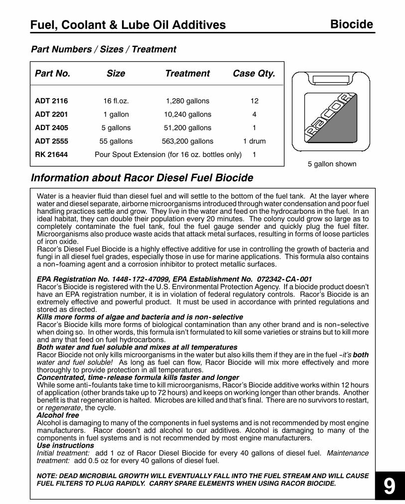
277
Fuel, Coolant & Lube Oil Additives Biocide
Part Numbers / Sizes / Treatment
Part No. Size Treatment Case Qty.
ADT 2116 16 fl.oz. 1,280 gallons 12
ADT 2201 1 gallon 10,240 gallons 4
ADT 2405 5 gallons 51,200 gallons 1
ADT 2555 55 gallons 563,200 gallons 1 drum
RK 21644 Pour Spout Extension (for 16 oz. bottles only) 1
Information about Racor Diesel Fuel Biocide
9
Water is a heavier fluid than diesel fuel and will settle to the bottom of the fuel tank. At the layer wherewater and diesel separate, airbornemicroorganisms introduced throughwater condensation and poor fuelhandling practices settle and grow. They live in the water and feed on the hydrocarbons in the fuel. In anideal habitat, they can double their population every 20 minutes. The colony could grow so large as tocompletely contaminate the fuel tank, foul the fuel gauge sender and quickly plug the fuel filter.Microorganisms also produce waste acids that attack metal surfaces, resulting in forms of loose particlesof iron oxide.Racor’s Diesel Fuel Biocide is a highly effective additive for use in controlling the growth of bacteria andfungi in all diesel fuel grades, especially those in use for marine applications. This formula also containsa non--foaming agent and a corrosion inhibitor to protect metallic surfaces.
EPA Registration No. 1448-172-47099, EPA Establishment No. 072342-CA-001Racor’s Biocide is registered with the U.S. Environmental Protection Agency. If a biocide product doesn’thave an EPA registration number, it is in violation of federal regulatory controls. Racor’s Biocide is anextremely effective and powerful product. It must be used in accordance with printed regulations andstored as directed.Kills more forms of algae and bacteria and is non-selectiveRacor’s Biocide kills more forms of biological contamination than any other brand and is non--selectivewhen doing so. In other words, this formula isn’t formulated to kill some varieties or strains but to kill moreand any that feed on fuel hydrocarbons.Both water and fuel soluble and mixes at all temperaturesRacor Biocide not only kills microorganisms in the water but also kills them if they are in the fuel --it’s bothwater and fuel soluble! As long as fuel can flow, Racor Biocide will mix more effectively and morethoroughly to provide protection in all temperatures.Concentrated, time- release formula kills faster and longerWhile some anti--foulants take time to kill microorganisms, Racor’s Biocide additive works within 12 hoursof application (other brands take up to 72 hours) and keeps on working longer than other brands. Anotherbenefit is that regeneration is halted. Microbes are killed and that’s final. There are no survivors to restart,or regenerate, the cycle.Alcohol freeAlcohol is damaging to many of the components in fuel systems and is not recommended by most enginemanufacturers. Racor doesn’t add alcohol to our additives. Alcohol is damaging to many of thecomponents in fuel systems and is not recommended by most engine manufacturers.Use instructionsInitial treatment: add 1 oz of Racor Diesel Biocide for every 40 gallons of diesel fuel. Maintenancetreatment: add 0.5 oz for every 40 gallons of diesel fuel.
NOTE: DEAD MICROBIAL GROWTH WILL EVENTUALLY FALL INTO THE FUEL STREAM AND WILL CAUSEFUEL FILTERS TO PLUG RAPIDLY. CARRY SPARE ELEMENTS WHEN USING RACOR BIOCIDE.
5 gallon shown

278
Fuel, Coolant & Lube Oil Additives Winter Plus+
Part Numbers / Sizes / Treatment
Part No. Size Treatment Case Qty.
ADT 4116 16 fl.oz. 128 gallons 12ADT 4201 1 gallon 1024 gallons 4ADT 4325 2.5 gallons 2560 gallons 2ADT 4555 55 gallons 56,320 gallons 1RK 21644 Pour Spout Extension (for 16 oz. bottle only) 1Note: This special product activates only after being mixed with diesel fuels.When not in use, store Racor Winter Plus+ above 32_F (0_C).
Information about Racor Diesel Winter Plus+
When diesel fuels are chilled an unusual problem arises:waxing. At about 10_F. and colder, fuel becomesthick and cloudy because paraffin wax crystals (and suspended water ice crystals) take shape. This isknown as the fuel cloud point (so named because the fuel begins to cloud or haze). Paraffin wax actuallytraps the fuel within the crystalline structure, reducing the ability to flow. Fuel filters gradually becomeplugged to thepoint of starving theengineof fuel. (If the fuelwaschilled another ten degrees it would freezecompletely and no longer flow! This is known as the fuel pour point).Racor’s Diesel Winter Plus+ is formulated to combat fuel icing and wax buildup. It retards ice formationand coats the systemwith a slip agent so icewill not cling and form plugs. Its formulation contains a cetaneimprover which enhances power delivery, starting, and helps engines run smoother and quieter.
Inhibits waxing, icing and gellingRacor’s Winter Plus+ modifies the structure of wax crystallization so that they cannot trap the fuel. Thiseffect lowers the pour point of No.2 diesel fuel and provides protection down to --32_F. Engine starting iseasier and continued operation in chilling climates is enhanced.Stabilizes fuel during prolonged storage and prevents corrosionA very important component of Winter Plus+ is the fuel stabilizer. During prolonged storage, fuel tendsto oxidize and degrade. The fuel quality can actually deteriorate to such a point that the engine is easilyfouled with contaminant by--products and water. The fuel stabilizer maintains the fuel quality (resistanceto degradation) so that it is not susceptible to deterioration. The potential for corrosive elements is alsoeliminated by providing a protective coating to bare metal surfaces, keeping water away.Prevents corrosion and is alcohol freeAnother component of Racor’s Winter Plus+ is a corrosion inhibitor that protects bare metal surfaces,protecting the fuel from further contamination. Alcohol is damaging to many of the components in fuelsystems and is not recommended by most engine manufacturers. Racor doesn’t add alcohol to ouradditives. In fact, we add a compound that actually causes water to coalesce (make larger droplets) soyour Racor Fuel Filter/Water Separator becomes much more efficient.
Use InstructionsThis product is most effective when added to the fuel tank, just prior to fueling. Do not add this productto fuel that is already gelled in the tank. Treatment Ratio: One (1) oz. treats 8 gallons of diesel fuel. Typicaltreat level is 530 PPM.
Additional Instructions1. This product activates whenmixed with diesel fuel. When not in use, store product above 32_ F (0_C).2. For extended cold weather operations, a diesel fuel heater may be needed as well. Refer to Section1 for Racor Diesel Fuel Heaters.
2.5 gallon shown

279
Fuel, Coolant & Lube Oil Additives Gas Conditioner Plus+
Part Numbers / Sizes / Treatment
Part No. Size Treatment Case Qty.
ADT 5116 16 fl.oz. 320 gallons 12
ADT 5325 2.5 gallons 6400 gallons 2
ADT 5555 55 gallons 140,800 gallons 1
RK 21644 Pour Spout Extension (for 16 oz. bottle only) 1
Note: Store product in a cool and dry location away from heat.
Information about Racor Gas Conditioner Plus+
9
Racor Gasoline Conditioner Plus+ enhances engine performance by cleaning the fuel injectors orcarburetor and intake systems, providing better combustion and therefore better fuel economy. It can beused with all types of gasoline engines, systems and all gasoline blends. For the best protection, use thisproduct regularly.
Cleans fuel injectors and carburetorsRacor’s Gasoline Conditioner Plus+ contains many fuel modifiers, providing a continuous cleaning actionwhich inhibits and removes carbon buildup and the accumulation of deposits. Gasoline Conditioner Plus+cleans fuel injectors therebymaintaining a proper spray pattern, improving efficiency and reducing injectornoise. Engine starting is easier and continued operation in all kinds of weather is enhanced.
Stabilizes fuel during prolonged storageAn important component of Gasoline Conditioner Plus+ is the fuel stabilizer. During prolonged storage,fuel tends to oxidize and degrade. The fuel quality can actually deteriorate to such a point that the engineis easily fouled with contaminant by--products and water. The fuel stabilizer maintains the fuel quality(resistance to degradation) so that it is not susceptible to deterioration.
Prevents corrosion and is alcohol freeThe potential for corrosive elements is also eliminated by providing a protective coating to bare metalsurfaces, keeping water away. Alcohol is damaging to many of the components in fuel systems and isnot recommended by most engine manufacturers. Racor doesn’t add alcohol to our additives.
Use InstructionsThis product is most effective when added to the fuel tank, just prior to fueling. Additive dosage will vary,depending on the end user’s desire to keep the system clean or to improve performance. Recommendedstandard dosage is one (1) oz. of Racor Gasoline Conditioner Plus+ for every 20 gallons of fuel.
Additional Instructions1. Store this product away from heat or flame in a cool, dry location, away from the reach of children.
1 gallon shown

280
Fuel, Coolant & Lube Oil Additives Lube Oil Treatment
Part Numbers / Sizes / Treatment
Part No. Size Treatment Case Qty.
ADT 7116 16 fl.oz. 2 gallons 12
ADT 7201 1 gallon 16 gallons 2
ADT 7555 55 gallons 880 gallons 1
RK 21644 Pour Spout Extension (for 16 oz. bottle only) 1
Information about Racor Lube Oil Treatment
Racor LubeOil Treatment is a fluorocarbon additive which contains an advanced, highly effective polymerlubricant. It provides a superior thin coating to protect precision engine parts and does not contain PTFEor Teflon* which have been known to fall from suspension and clog precision engine components.Manyof todays leading oil companies are nowslowlymakingway to the retail counterswith their own typesof treatments but only Racor has sourced an independent research laboratory that has developed thisunique product and only Racor may offer it.
Reduces engine wear, noise and heat, increasing power, mileage and engine lifeRacor’s Lube Oil Treatment contains a proprietary ingredient, not available in any other competitiveproduct, that offers superior lubrication even with standard engine oils. A protective barrier reducesfriction, allowing parts to move smoothly. Reducing friction also reduces noise and heat that allowsengines to run quieter and cooler. With continuous use at every oil change, you can assure your engineperformance and extend its useful service life.
Compatible with all motor oils, and with diesel or gasoline enginesThis product works in any grade of motor oil, both petroleum and synthetic, and in any kind of an engine.Put Racor’s Lube Oil Treatment to the test in all of your engines.
Reduces harmful emissions and controls foamingRacor’s Lube Oil Treatment contains modifiers that stabilize oil reactions to crankcase heat and pressureto limit harmful emissions usually lost at crankcase breathers or into clean air intakes. Anti--foamingingredients control crankcase lubrication system foam accumulation.
Use InstructionsThis product may be added to engine oil at any time. Treatment Ratio: two (2) oz. treat one quart of lubeoil. Recommended for use after every four (4) oil changes, andmay be used as often as every oil change.
Additional Instructions1. This product is most effective with continued use.2. Blend using conventional equipment and methods for blending finished fluids. Do not heat over 140oF(60oC) for prolonged periods to avoid possible release of alkyl mercaptans and/or hydrogen sulfide.
*Teflon, is a registered trademark of the E.I. DuPont de Nemours & Co.
55 gallon drum shown
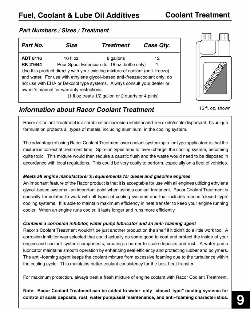
281
Fuel, Coolant & Lube Oil Additives Coolant Treatment
Part Numbers / Sizes / Treatment
Part No. Size Treatment Case Qty.
ADT 8116 16 fl.oz. 8 gallons 12RK 21644 Pour Spout Extension (for 16 oz. bottle only) 1Use this product directly with your existing mixture of coolant (anti--freeze)and water. For use with ethylene glycol--based anti--freeze/coolant only; donot use with EHA or Dexcool type systems. Always consult your dealer orowner’s manual for warranty restrictions.
(1 fl.oz treats 1/2 gallon or 2 quarts or 4 pints)
Information about Racor Coolant Treatment
9
Racor’s Coolant Treatment is a combination corrosion inhibitor and iron oxide/scale dispersant. Its uniqueformulation protects all types of metals, including aluminum, in the cooling system.
The advantage of using Racor Coolant Treatment over coolant system spin--on type applicators is that themixture is correct at treatment time. Spin--on types tend to ’over--charge’ the cooling system, becomingquite toxic. This mixture would then require a caustic flush and the waste would need to be disposed inaccordance with local regulations. This could be very costly to perform, especially on a fleet of vehicles.
Meets all engine manufacturer’s requirements for diesel and gasoline enginesAn important feature of the Racor product is that it is acceptable for use with all engines utilizing ethyleneglycol--based systems --an important point when using a coolant treatment. Racor Coolant Treatment isspecially formulated to work with all types of cooling systems and that includes marine ’closed--type’cooling systems. It is able to maintain maximum efficiency in heat transfer to keep your engine runningcooler. When an engine runs cooler, it lasts longer and runs more efficiently.
Contains a corrosion inhibitor, water pump lubricator and an anti- foaming agentRacor’s Coolant Treatment wouldn’t be just another product on the shelf if it didn’t do a little work too. Acorrosion inhibitor was selected that could actually do some good to coat and protect the inside of yourengine and coolant system components, creating a barrier to scale deposits and rust. A water pumplubricator maintains smooth operation by enhancing seal efficiency and protecting rubber and polymers.The anti--foaming agent keeps the coolant mixture from excessive foaming due to the turbulence withinthe cooling cycle. This maintains better coolant consistency for the best heat transfer.
For maximum protection, always treat a fresh mixture of engine coolant with Racor Coolant Treatment.
Note: Racor Coolant Treatment can be added to water--only “closed--type” cooling systems forcontrol of scale deposits, rust, water pump/seal maintenance, and anti--foaming characteristics.
16 fl. oz. shown


