
*GTA 05-07-013
Rapid FieldClassification Booklet
1 July 2006
HEADQUARTERS, DEPARTMENT OF THE ARMY
DISTRIBUTION: United States Army Training Support Centers.DISTRIBUTION RESTRICTION: Approved for public release; distribution is unlimited.
*This GTA supersedes GTA 05-07-013, 1 January 2003.
new05-07-013.pdf 1 6/14/2006 11:48:54 AMnew05-07-013.pdf 1 6/14/2006 12:31:16 PM
GTA 05-07-013
2
RAPID FIELD CLASSIFICATION BOOKLETPurpose. Bridge and vehicle classification allows vehicle operators to avoid bridge failure due to overloading. Vehicle operators may drive across bridges without restrictions if their vehicles’ class numbers are less than or equal to the bridge class number. Field Manual (FM) 5-170 shows classifications for standard vehicles and the procedure for classifying vehicles. Refer to FM 3-34.343 for a complete discussion of bridge classification procedures. This GTA provides a rapid field method of establishing bridge capacity in the field, but only as a temporary measure. An analytical classification must be performed as soon as possible in order to actually classify the bridge and post a classification sign.
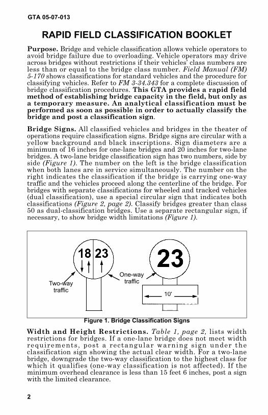
Bridge Signs. All classified vehicles and bridges in the theater of operations require classification signs. Bridge signs are circular with a yellow background and black inscriptions. Sign diameters are a minimum of 16 inches for one-lane bridges and 20 inches for two-lane bridges. A two-lane bridge classification sign has two numbers, side by side (Figure 1). The number on the left is the bridge classification when both lanes are in service simultaneously. The number on the right indicates the classification if the bridge is carrying one-way traffic and the vehicles proceed along the centerline of the bridge. For bridges with separate classifications for wheeled and tracked vehicles (dual classification), use a special circular sign that indicates both classifications (Figure 2, page 2). Classify bridges greater than class 50 as dual-classification bridges. Use a separate rectangular sign, if necessary, to show bridge width limitations (Figure 1).
Figure 1. Bridge Classification Signs
Two-way traffic
One-waytraffic
10'
Width and Height Restrictions. Table 1, page 2, lists width restrictions for bridges. If a one-lane bridge does not meet width requirements, post a rectangular warning sign under the classification sign showing the actual clear width. For a two-lane bridge, downgrade the two-way classification to the highest class for which it qualifies (one-way classification is not affected). If the minimum overhead clearance is less than 15 feet 6 inches, post a sign with the limited clearance.
new05-07-013.pdf 2 6/14/2006 11:48:54 AMnew05-07-013.pdf 2 6/14/2006 12:31:17 PM
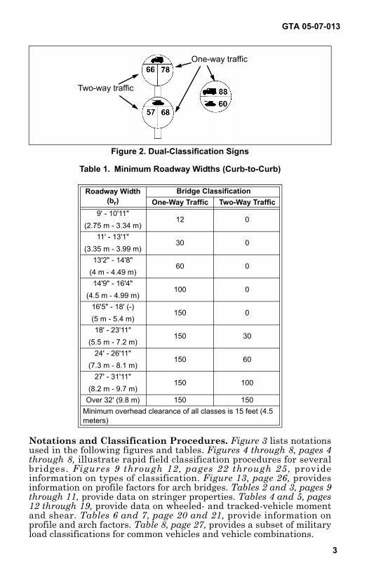
Figure 2. Dual-Classification Signs
Two-way traffic
One-way traffic
Table 1. Minimum Roadway Widths (Curb-to-Curb)
Roadway Width(br)
Bridge ClassificationOne-Way Traffic Two-Way Traffic
9' - 10'11"(2.75 m - 3.34 m)
12 0
11' - 13'1"(3.35 m - 3.99 m)
30 0
13'2" - 14'8"(4 m - 4.49 m)
60 0
14'9" - 16'4"(4.5 m - 4.99 m)
100 0
16'5" - 18' (-)(5 m - 5.4 m)
150 0
18' - 23'11"(5.5 m - 7.2 m)
150 30
24' - 26'11"(7.3 m - 8.1 m)
150 60
27' - 31'11"(8.2 m - 9.7 m)
150 100
Over 32' (9.8 m) 150 150Minimum overhead clearance of all classes is 15 feet (4.5 meters)
GTA 05-07-013
3
Notations and Classification Procedures. Figure 3 lists notations used in the following figures and tables. Figures 4 through 8, pages 4 through 8, illustrate rapid field classification procedures for several bridges. Figures 9 through 12, pages 22 through 25 , provide information on types of classification. Figure 13, page 26, provides information on profile factors for arch bridges. Tables 2 and 3, pages 9 through 11, provide data on stringer properties. Tables 4 and 5, pages 12 through 19, provide data on wheeled- and tracked-vehicle moment and shear. Tables 6 and 7, page 20 and 21, provide information on profile and arch factors. Table 8, page 27, provides a subset of military load classifications for common vehicles and vehicle combinations.
new05-07-013.pdf 3 6/14/2006 11:48:55 AMnew05-07-013.pdf 3 6/14/2006 12:31:17 PM
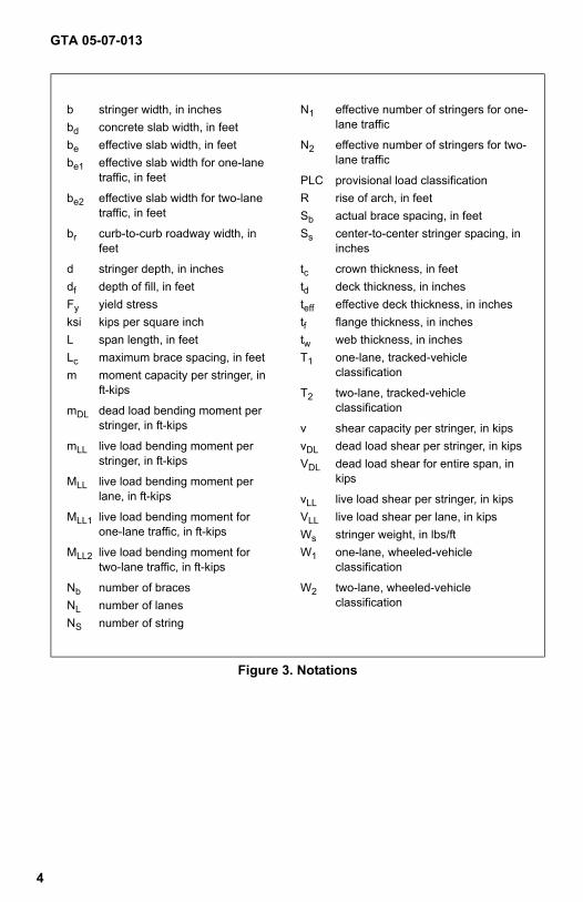
Figure 3. Notations
b stringer width, in inches N1 effective number of stringers for one-lane trafficbd concrete slab width, in feet
be effective slab width, in feet N2 effective number of stringers for two-lane trafficbe1 effective slab width for one-lane
traffic, in feet PLC provisional load classificationbe2 effective slab width for two-lane
traffic, in feetR rise of arch, in feetSb actual brace spacing, in feet
br curb-to-curb roadway width, in feet
Ss center-to-center stringer spacing, in inches
d stringer depth, in inches tc crown thickness, in feetdf depth of fill, in feet td deck thickness, in inchesFy yield stress teff effective deck thickness, in inchesksi kips per square inch tf flange thickness, in inchesL span length, in feet tw web thickness, in inchesLc maximum brace spacing, in feet T1 one-lane, tracked-vehicle
classificationm moment capacity per stringer, in ft-kips T2 two-lane, tracked-vehicle
classificationmDL dead load bending moment per stringer, in ft-kips v shear capacity per stringer, in kips
mLL live load bending moment per stringer, in ft-kips
vDL dead load shear per stringer, in kipsVDL dead load shear for entire span, in
kipsMLL live load bending moment perlane, in ft-kips vLL live load shear per stringer, in kips
MLL1 live load bending moment forone-lane traffic, in ft-kips
VLL live load shear per lane, in kipsWs stringer weight, in lbs/ft
MLL2 live load bending moment fortwo-lane traffic, in ft-kips
W1 one-lane, wheeled-vehicle classification
Nb number of braces W2 two-lane, wheeled-vehicle classificationNL number of lanes
NS number of string
GTA 05-07-013
4
new05-07-013.pdf 4 6/14/2006 11:48:55 AMnew05-07-013.pdf 4 6/14/2006 12:31:17 PM
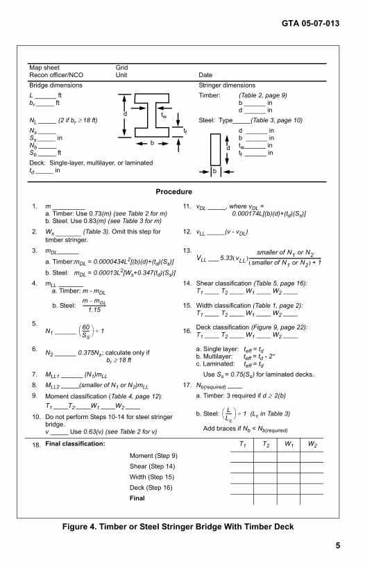
Figure 4. Timber or Steel Stringer Bridge With Timber Deck
Map sheetRecon officer/NCO
GridUnit Date
Bridge dimensions Stringer dimensionsL ______ ftbr _____ ft
Timber: (Table 2, page 9)b ______ ind ______ in
NL _____ (2 if br ≥ 18 ft) Steel: Type_____(Table 3, page 10)Ns _____Ss _____ inNb _____Sb _____ ft
d ______ inb ______ intw______ intf ______ in
Deck: Single-layer, multilayer, or laminatedtd _____ in
Procedure
1. m _________a. Timber: Use 0.73(m) (see Table 2 for m) b. Steel: Use 0.83(m) (see Table 3 for m)
11. vDL _____, where vDL = 0.000174L[(b)(d)+(td)(Ss)]
2. Ws _________ (Table 3). Omit this step for timber stringer.
12. vLL _____(v - vDL)
3. mDL______
a. Timber:mDL = 0.0000434L2[(b)(d)+(td)(Ss)]
b. Steel: mDL = 0.00013L2[Ws+0.347(td)(Ss)]
13.VLL ___
4. mLL _______a. Timber: m - mDL
b. Steel:
14.
15.
Shear classification (Table 5, page 16):T1 ____ T2 ____ W1 ____ W2 ____
Width classification (Table 1, page 2):T1 ____ T2 ____ W1 ____ W2 ____
5.N1 ______ 16. Deck classification (Figure 9, page 22):
T1 ____ T2 ____ W1 ____ W2 ____
6. N2 ______ 0.375Ns ; calculate only if br ≥ 18 ft
a. Single layer: teff = tdb. Multilayer: teff = td - 2 ″c. Laminated: teff = td
7. MLL1 ______ (N1)mLL Use Ss = 0.75(Ss ) for laminated decks.8. MLL2 _____(smaller of N1 or N2)mLL 17. Nb(required) ____9. Moment classification (Table 4, page 12):
T1 ____T2 ____W1 ____W2 ____a. Timber: 3 required if d ≥ 2(b)
b. Steel: (Lc in Table 3)
Add braces if Nb < Nb(required)
10. Do not perform Steps 10-14 for steel stringer bridge.v _____ Use 0.63(v) (see Table 2 for v)
18. Final classification: T1 T2 W1 W2
Moment (Step 9)Shear (Step 14)Width (Step 15)Deck (Step 16)Final
d tw
tfb
b
d
5.33 vLL( )smaller of N1 or N2
smaller of N1 or N2( ) 1+-------------------------------------------------------------------
m mDL–1.15
----------------------
60SS-------
1+
LLc------
1+
GTA 05-07-013
5
new05-07-013.pdf 5 6/14/2006 11:48:55 AMnew05-07-013.pdf 5 6/14/2006 12:31:17 PM
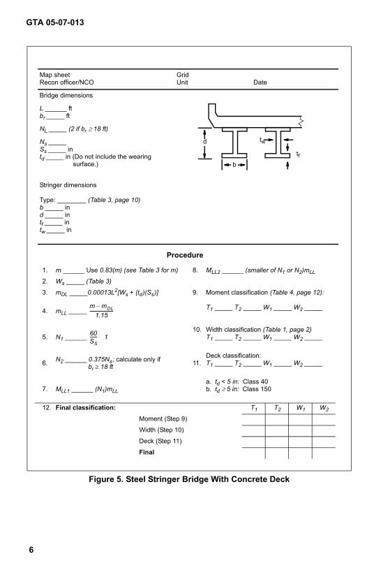
Figure 5. Steel Stringer Bridge With Concrete Deck
Map sheetRecon officer/NCO
GridUnit Date
Bridge dimensions
L ______ ftbr _____ ft
NL _____ (2 if br ≥ 18 ft)
Ns _____Ss _____ intd _____ in (Do not include the wearing
surface.)
Stringer dimensions
Type: ________ (Table 3, page 10)b _____ ind _____ intf _____ intw _____ in
Procedure
1. m ______ Use 0.83(m) (see Table 3 for m) 8. MLL2 ______ (smaller of N1 or N2)mLL
2. Ws _____ (Table 3)
3. mDL _____0.00013L2[Ws + (td )(Ss )] 9. Moment classification (Table 4, page 12):
4. mLL _____ T1 _____ T2 _____ W1 _____ W2 _____
5. N1 ______ 10. Width classification (Table 1, page 2)
T1 _____ T2 _____ W1 _____ W2 _____
6. N2 ______ 0.375Ns ; calculate only if br ≥ 18 ft 11.
Deck classification:T1 _____ T2 _____ W1 _____ W2 _____
7. MLL1 ______ (N1)mLL
a. td < 5 in: Class 40b. td ≥ 5 in: Class 150
12. Final classification: T1 T2 W1 W2
Moment (Step 9)
Width (Step 10)
Deck (Step 11)
Final
d
b
tw
tf
m mDL–1.15
----------------------
60SS------- 1
GTA 05-07-013
6
new05-07-013.pdf 6 6/14/2006 11:48:55 AMnew05-07-013.pdf 6 6/14/2006 12:31:17 PM
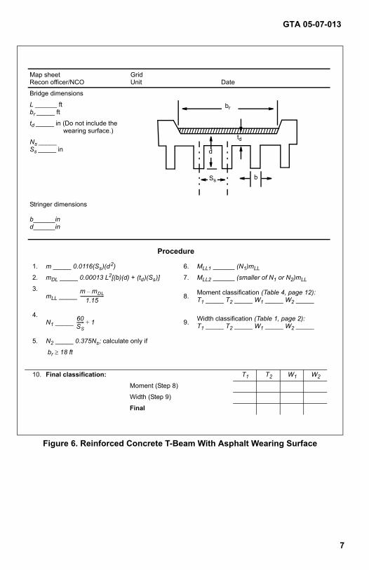
Figure 6. Reinforced Concrete T-Beam With Asphalt Wearing Surface
Map sheetRecon officer/NCO
GridUnit Date
Bridge dimensions
L ______ ftbr _____ ft
td _____ in (Do not include the wearing surface.)
Ns _____Ss _____ in
Stringer dimensions
b______ind______in
Procedure
1. m _____ 0.0116(Ss )(d 2) 6. MLL1 ______ (N1)mLL
2. mDL _____ 0.00013 L2[(b)(d) + (td )(Ss )] 7. MLL2 ______ (smaller of N1 or N2)mLL
3.mLL _____ 8. Moment classification (Table 4, page 12):
T1 _____ T2 _____ W1 _____ W2 _____
4.N1 _____ 9. Width classification (Table 1, page 2):
T1 _____ T2 _____ W1 _____ W2 _____
5. N2 _____ 0.375Ns ; calculate only if
br ≥ 18 ft
10. Final classification: T1 T2 W1 W2
Moment (Step 8)
Width (Step 9)
Final
br
td
d
bSs
m mDL–1.15
----------------------
60SS------- 1+
GTA 05-07-013
7
new05-07-013.pdf 7 6/14/2006 11:48:55 AMnew05-07-013.pdf 7 6/14/2006 12:31:17 PM
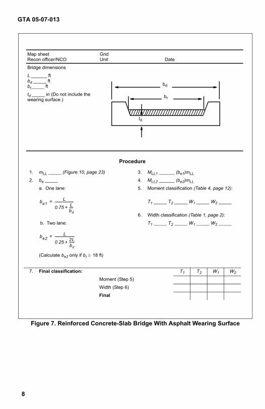
Figure 7. Reinforced Concrete-Slab Bridge With Asphalt Wearing Surface
Map sheetRecon officer/NCO
GridUnit Date
Bridge dimensions
L ______ ftbd _____ ftbr_____ ft
td _____ in (Do not include the wearing surface.)
Procedure
1. mLL _____ (Figure 10, page 23) 3. MLL1 ______ (be1)mLL
2. be _____ 4. MLL2 ______ (be2)mLL
a. One lane: 5. Moment classification (Table 4, page 12):
T1 _____ T2 _____ W1 _____ W2 _____
6. Width classification (Table 1, page 2):
b. Two lane: T1 _____ T2 _____ W1 _____ W2 _____
(Calculate be2 only if br ≥ 18 ft)
7. Final classification: T1 T2 W1 W2
Moment (Step 5)
Width (Step 6)
Final
br
td
bd
be1L
0.75 Lbd-----+
------------------------=
be2L
0.25 2Lbd-------+
-------------------------=
GTA 05-07-013
8
new05-07-013.pdf 8 6/14/2006 11:48:55 AMnew05-07-013.pdf 8 6/14/2006 12:31:17 PM
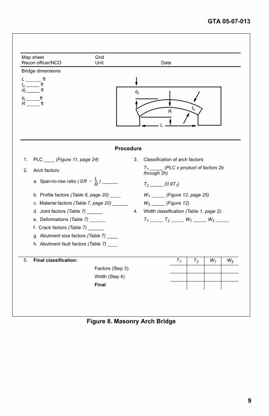
Figure 8. Masonry Arch Bridge
Map sheetRecon officer/NCO
GridUnit Date
Bridge dimensions
L ______ fttc _____ ftdf _____ ft
br _____ft R _____ ft
Procedure
1. PLC ____ (Figure 11, page 24) 3. Classification of arch factors:
2. Arch factors: T1 _____ (PLC x product of factors 2b through 2h)
a. Span-to-rise ratio ( ) ______ T2 _____ (0.9T1)
b. Profile factors (Table 6, page 20) ____ W1 _____ (Figure 12, page 25)
c. Material factors (Table 7, page 20) ______ W2 _____ (Figure 12)
d. Joint factors (Table 7) ______ 4. Width classification (Table 1, page 2):
e. Deformations (Table 7) ______ T1 _____ T2 _____ W1 _____ W2 _____
f. Crack factors (Table 7) ______
g. Abutment size factors (Table 7) ____
h. Abutment fault factors (Table 7) ____
5. Final classification: T1 T2 W1 W2
Factors (Step 3)
Width (Step 4)
Final
df
Rtc
L
SR LR----=
GTA 05-07-013
9
new05-07-013.pdf 9 6/14/2006 11:48:55 AMnew05-07-013.pdf 9 6/14/2006 12:31:17 PM
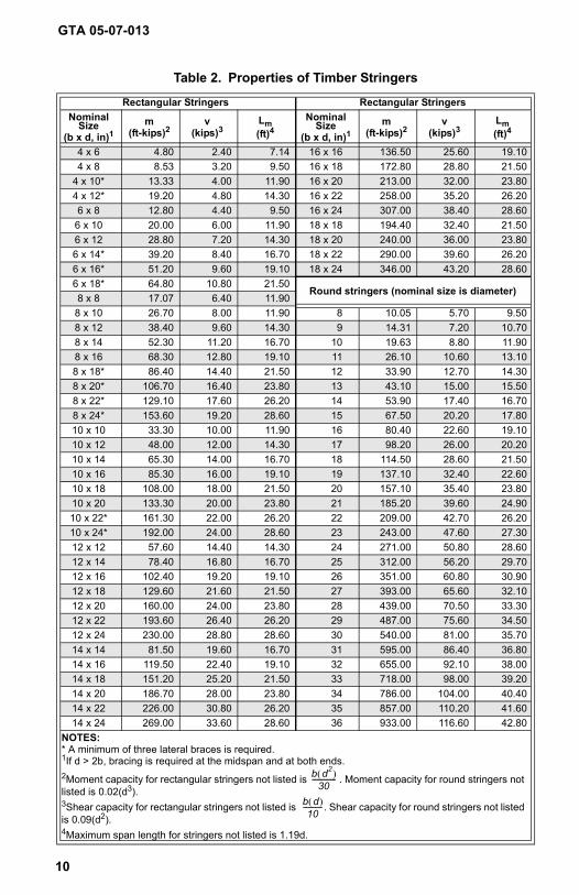
Table 2. Properties of Timber Stringers
Rectangular Stringers Rectangular StringersNominal
Size (b x d, in)1
m(ft-kips)2
v(kips)3
Lm(ft)4
Nominal Size
(b x d, in)1m
(ft-kips)2v
(kips)3Lm(ft)4
4 x 6 4.80 2.40 7.14 16 x 16 136.50 25.60 19.104 x 8 8.53 3.20 9.50 16 x 18 172.80 28.80 21.50
4 x 10* 13.33 4.00 11.90 16 x 20 213.00 32.00 23.804 x 12* 19.20 4.80 14.30 16 x 22 258.00 35.20 26.206 x 8 12.80 4.40 9.50 16 x 24 307.00 38.40 28.606 x 10 20.00 6.00 11.90 18 x 18 194.40 32.40 21.506 x 12 28.80 7.20 14.30 18 x 20 240.00 36.00 23.806 x 14* 39.20 8.40 16.70 18 x 22 290.00 39.60 26.206 x 16* 51.20 9.60 19.10 18 x 24 346.00 43.20 28.606 x 18* 64.80 10.80 21.50
Round stringers (nominal size is diameter)8 x 8 17.07 6.40 11.908 x 10 26.70 8.00 11.90 8 10.05 5.70 9.508 x 12 38.40 9.60 14.30 9 14.31 7.20 10.708 x 14 52.30 11.20 16.70 10 19.63 8.80 11.908 x 16 68.30 12.80 19.10 11 26.10 10.60 13.108 x 18* 86.40 14.40 21.50 12 33.90 12.70 14.308 x 20* 106.70 16.40 23.80 13 43.10 15.00 15.508 x 22* 129.10 17.60 26.20 14 53.90 17.40 16.708 x 24* 153.60 19.20 28.60 15 67.50 20.20 17.8010 x 10 33.30 10.00 11.90 16 80.40 22.60 19.1010 x 12 48.00 12.00 14.30 17 98.20 26.00 20.2010 x 14 65.30 14.00 16.70 18 114.50 28.60 21.5010 x 16 85.30 16.00 19.10 19 137.10 32.40 22.6010 x 18 108.00 18.00 21.50 20 157.10 35.40 23.8010 x 20 133.30 20.00 23.80 21 185.20 39.60 24.9010 x 22* 161.30 22.00 26.20 22 209.00 42.70 26.2010 x 24* 192.00 24.00 28.60 23 243.00 47.60 27.3012 x 12 57.60 14.40 14.30 24 271.00 50.80 28.6012 x 14 78.40 16.80 16.70 25 312.00 56.20 29.7012 x 16 102.40 19.20 19.10 26 351.00 60.80 30.9012 x 18 129.60 21.60 21.50 27 393.00 65.60 32.1012 x 20 160.00 24.00 23.80 28 439.00 70.50 33.3012 x 22 193.60 26.40 26.20 29 487.00 75.60 34.5012 x 24 230.00 28.80 28.60 30 540.00 81.00 35.7014 x 14 81.50 19.60 16.70 31 595.00 86.40 36.8014 x 16 119.50 22.40 19.10 32 655.00 92.10 38.0014 x 18 151.20 25.20 21.50 33 718.00 98.00 39.2014 x 20 186.70 28.00 23.80 34 786.00 104.00 40.4014 x 22 226.00 30.80 26.20 35 857.00 110.20 41.6014 x 24 269.00 33.60 28.60 36 933.00 116.60 42.80
NOTES:* A minimum of three lateral braces is required.1If d > 2b, bracing is required at the midspan and at both ends.2Moment capacity for rectangular stringers not listed is b d2( )
30-------------- . Moment capacity for round stringers not
listed is 0.02(d3).3Shear capacity for rectangular stringers not listed is b d( )
10----------- . Shear capacity for round stringers not listed
is 0.09(d2).4Maximum span length for stringers not listed is 1.19d.
GTA 05-07-013
10
new05-07-013.pdf 10 6/14/2006 11:48:55 AMnew05-07-013.pdf 10 6/14/2006 12:31:17 PM
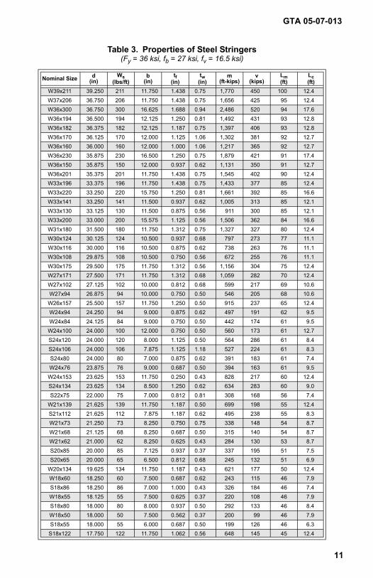
Table 3. Properties of Steel Stringers(Fy = 36 ksi, fb = 27 ksi, fv = 16.5 ksi)
Nominal Size d(in)
Ws(lbs/ft)
b(in)
tf(in)
tw(in)
m(ft-kips)
v(kips)
Lm(ft)
Lc(ft)
W39x211 39.250 211 11.750 1.438 0.75 1,770 450 100 12.4W37x206 36.750 206 11.750 1.438 0.75 1,656 425 95 12.4W36x300 36.750 300 16.625 1.688 0.94 2,486 520 94 17.6W36x194 36.500 194 12.125 1.250 0.81 1,492 431 93 12.8W36x182 36.375 182 12.125 1.187 0.75 1,397 406 93 12.8W36x170 36.125 170 12.000 1.125 1.06 1,302 381 92 12.7W36x160 36.000 160 12.000 1.000 1.06 1,217 365 92 12.7W36x230 35.875 230 16.500 1.250 0.75 1,879 421 91 17.4W36x150 35.875 150 12.000 0.937 0.62 1,131 350 91 12.7W36x201 35.375 201 11.750 1.438 0.75 1,545 402 90 12.4W33x196 33.375 196 11.750 1.438 0.75 1,433 377 85 12.4W33x220 33.250 220 15.750 1.250 0.81 1,661 392 85 16.6W33x141 33.250 141 11.500 0.937 0.62 1,005 313 85 12.1W33x130 33.125 130 11.500 0.875 0.56 911 300 85 12.1W33x200 33.000 200 15.575 1.125 0.56 1,506 362 84 16.6W31x180 31.500 180 11.750 1.312 0.75 1,327 327 80 12.4W30x124 30.125 124 10.500 0.937 0.68 797 273 77 11.1W30x116 30.000 116 10.500 0.875 0.62 738 263 76 11.1W30x108 29.875 108 10.500 0.750 0.56 672 255 76 11.1W30x175 29.500 175 11.750 1.312 0.56 1,156 304 75 12.4W27x171 27.500 171 11.750 1.312 0.68 1,059 282 70 12.4W27x102 27.125 102 10.000 0.812 0.68 599 217 69 10.6W27x94 26.875 94 10.000 0.750 0.50 546 205 68 10.6
W26x157 25.500 157 11.750 1.250 0.50 915 237 65 12.4W24x94 24.250 94 9.000 0.875 0.62 497 191 62 9.5W24x84 24.125 84 9.000 0.750 0.50 442 174 61 9.5
W24x100 24.000 100 12.000 0.750 0.50 560 173 61 12.7S24x120 24.000 120 8.000 1.125 0.50 564 286 61 8.4S24x106 24.000 106 7.875 1.125 1.18 527 224 61 8.3S24x80 24.000 80 7.000 0.875 0.62 391 183 61 7.4W24x76 23.875 76 9.000 0.687 0.50 394 163 61 9.5
W24x153 23.625 153 11.750 0.250 0.43 828 217 60 12.4S24x134 23.625 134 8.500 1.250 0.62 634 283 60 9.0S22x75 22.000 75 7.000 0.812 0.81 308 168 56 7.4
W21x139 21.625 139 11.750 1.187 0.50 699 198 55 12.4S21x112 21.625 112 7.875 1.187 0.62 495 238 55 8.3W21x73 21.250 73 8.250 0.750 0.75 338 148 54 8.7W21x68 21.125 68 8.250 0.687 0.50 315 140 54 8.7W21x62 21.000 62 8.250 0.625 0.43 284 130 53 8.7S20x85 20.000 85 7.125 0.937 0.37 337 195 51 7.5S20x65 20.000 65 6.500 0.812 0.68 245 132 51 6.9
W20x134 19.625 134 11.750 1.187 0.43 621 177 50 12.4W18x60 18.250 60 7.500 0.687 0.62 243 115 46 7.9S18x86 18.250 86 7.000 1.000 0.43 326 184 46 7.4W18x55 18.125 55 7.500 0.625 0.37 220 108 46 7.9S18x80 18.000 80 8.000 0.937 0.50 292 133 46 8.4W18x50 18.000 50 7.500 0.562 0.37 200 99 46 7.9S18x55 18.000 55 6.000 0.687 0.50 199 126 46 6.3
S18x122 17.750 122 11.750 1.062 0.56 648 145 45 12.4
GTA 05-07-013
11
new05-07-013.pdf 11 6/14/2006 11:48:55 AMnew05-07-013.pdf 11 6/14/2006 12:31:18 PM
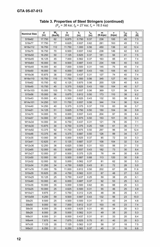
Table 3. Properties of Steel Stringers (continued)(Fy = 36 ksi, fb = 27 ksi, fv = 16.5 ksi)
Nominal Size d(in)
Ws(lbs/ft)
b(in)
tf(in)
tw(in)
m(ft-kips)
v(kips)
Lm(ft)
Lc(ft)
S18x62 17.750 62 6.875 0.750 0.37 238 100 45 7.3S18x77 17.750 77 6.625 0.937 0.62 281 163 45 7.0
W16x112 16.750 112 11.750 1.000 0.56 450 136 42 12.4S16x70 16.750 70 6.500 0.937 0.62 238 146 42 6.9W16x50 16.250 50 7.125 0.625 0.37 181 94 41 7.5W16x45 16.125 45 7.000 0.562 0.37 163 85 41 7.4W16x64 16.000 64 8.500 0.687 0.43 234 106 40 9.0W16x40 16.000 40 7.000 0.500 0.31 145 75 40 7.4S16x50 16.000 50 6.000 0.687 0.43 155 105 40 6.3W16x36 15.875 36 7.000 0.437 0.31 127 74 40 7.4W16x110 15.750 110 11.750 1.000 0.56 345 127 40 12.4S16x62 15.750 62 6.125 0.875 0.56 200 129 40 6.5S16x45 15.750 45 5.375 0.625 0.43 150 104 40 5.7
W15x103 15.000 103 11.750 0.937 0.56 369 121 38 12.4S15x56 15.000 56 5.875 0.812 0.50 173 110 38 6.2S15x43 15.000 43 5.500 0.625 0.43 132 93 38 5.8
W14x101 14.250 101 11.750 0.937 0.56 344 114 36 12.4S14x40 14.250 40 5.375 0.375 0.37 119 83 36 5.7S14x51 14.125 51 5.625 0.750 0.50 150 104 36 5.9S14x70 14.000 70 8.000 0.937 0.43 204 87 35 8.4S14x57 14.000 57 6.000 0.875 0.50 153 101 35 6.3W14x34 14.000 34 6.750 0.437 0.31 121 78 35 7.1W14x30 13.875 30 6.750 0.375 0.25 109 61 35 7.1W14x92 13.375 92 11.750 0.875 0.50 297 96 34 12.4S14x46 13.375 46 5.375 0.687 0.50 126 99 34 5.7S13x35 13.000 35 5.000 0.625 0.37 85 72 33 5.3S13x41 12.625 41 5.125 0.687 0.37 108 104 32 5.4W12x36 12.250 36 6.625 0.565 0.31 103 56 31 7.0S12x65 12.000 65 8.000 0.937 0.43 182 73 30 8.4W12x27 12.000 27 6.500 0.375 0.25 76 44 30 6.9S12x50 12.000 50 5.500 0.687 0.68 113 120 30 5.8S12x32 12.000 32 5.000 0.562 0.37 81 62 30 5.3S12x34 11.250 34 4.750 0.625 0.43 81 72 28 5.0W11x76 11.000 76 11.000 0.812 0.50 202 67 28 11.6S10x29 10.625 29 4.750 0.562 0.31 67 48 27 5.0W10x25 10.125 25 5.750 0.437 0.25 59 38 25 6.1S10x40 10.000 40 6.000 0.687 0.37 92 53 25 6.3S10x35 10.000 35 5.000 0.500 0.62 65 88 25 5.3S10x25 10.000 25 4.625 0.500 0.31 55 46 25 4.9W10x21 9.875 21 5.750 0.312 0.25 48 36 25 6.1W10x59 9.250 59 9.500 0.687 0.43 132 56 23 10.0S9x25 9.500 25 4.500 0.500 0.31 51 43 24 4.8S9x50 9.000 50 7.000 0.812 0.37 103 45 23 7.4S8x35 8.000 35 6.000 0.625 0.31 65 34 20 6.3S8x28 8.000 28 5.000 0.562 0.31 49 35 20 5.3W8x31 8.000 31 8.000 0.437 0.31 61 33 20 8.4W8x44 7.875 44 7.875 0.625 0.75 81 40 20 8.3W7x35 7.125 35 7.125 0.562 0.37 58 37 18 7.5W6x31 6.250 31 6.250 0.562 0.37 45 31 16 6.6
GTA 05-07-013
12
new05-07-013.pdf 12 6/14/2006 11:48:55 AMnew05-07-013.pdf 12 6/14/2006 12:31:18 PM
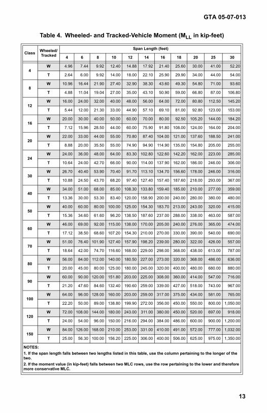
Table 4. Wheeled- and Tracked-Vehicle Moment (MLL in kip-feet)
Class Wheeled/Tracked
Span Length (feet)
4 6 8 10 12 14 16 18 20 25 30
4W 4.96 7.44 9.92 12.40 14.88 17.92 21.40 25.60 30.00 41.00 52.20
T 2.64 6.00 9.92 14.00 18.00 22.10 25.90 29.90 34.00 44.00 54.00
8W 10.96 16.44 21.90 27.40 32.90 38.30 43.60 49.30 54.80 71.00 93.60
T 4.88 11.04 19.04 27.00 35.00 43.10 50.90 59.00 66.80 87.00 106.80
12W 16.00 24.00 32.00 40.00 48.00 56.00 64.00 72.00 80.80 112.50 145.20
T 5.44 12.00 21.30 33.00 44.90 57.10 69.10 81.00 92.80 123.00 153.00
16W 20.00 30.00 40.00 50.00 60.00 70.00 80.00 92.50 105.20 144.00 184.20
T 7.12 15.96 28.50 44.00 60.00 75.90 91.80 108.00 124.00 164.00 204.00
20W 22.00 33.00 44.00 55.00 70.80 87.40 104.00 121.00 137.60 188.50 241.00
T 8.88 20.00 35.50 55.00 74.90 94.90 114.90 135.00 154.80 205.00 255.00
24W 24.00 36.00 48.00 64.00 83.30 102.80 122.60 142.20 162.00 223.00 285.00
T 10.64 24.00 42.70 66.00 90.00 114.00 137.90 162.00 186.00 246.00 306.00
30W 26.70 40.40 53.90 70.40 91.70 113.10 134.70 156.60 178.00 246.00 316.00
T 10.88 24.50 43.70 68.20 97.40 127.40 157.40 187.60 218.00 293.00 367.00
40W 34.00 51.00 68.00 85.00 108.30 133.80 159.40 185.00 210.00 277.00 359.00
T 13.36 30.00 53.30 83.40 120.00 158.90 200.00 240.00 280.00 380.00 480.00
50W 40.00 60.00 80.00 100.00 125.00 154.30 183.70 213.00 243.00 320.00 415.00
T 15.36 34.60 61.60 96.20 138.50 187.60 237.00 288.00 338.00 463.00 587.00
60W 46.00 69.00 92.00 115.00 138.00 170.00 205.00 240.00 276.00 365.00 474.00
T 17.12 38.50 68.60 107.20 154.30 210.00 270.00 330.00 390.00 540.00 690.00
70W 51.00 76.40 101.90 127.40 157.90 198.20 239.00 280.00 322.00 426.00 557.00
T 18.64 42.00 74.70 116.60 168.00 229.00 298.00 368.00 438.00 613.00 787.00
80W 56.00 84.00 112.00 140.00 180.50 227.00 273.00 320.00 368.00 486.00 636.00
T 20.00 45.00 80.00 125.00 180.00 245.00 320.00 400.00 480.00 680.00 880.00
90W 60.00 90.00 120.00 151.80 203.00 225.00 308.00 360.00 414.00 547.00 716.00
T 21.20 47.60 84.60 132.40 190.60 259.00 339.00 427.00 518.00 743.00 967.00
100W 64.00 96.00 128.00 160.00 203.00 259.00 317.00 375.00 434.00 581.00 765.00
T 22.20 50.00 89.00 138.80 199.90 272.00 356.00 450.00 550.00 800.00 1,050.00
120W 72.00 108.00 144.00 180.00 243.00 311.00 380.00 450.00 520.00 697.00 918.00
T 24.00 54.00 96.00 150.00 216.00 294.00 384.00 486.00 600.00 900.00 1,200.00
150W 84.00 126.00 168.00 210.00 253.00 331.00 410.00 491.00 572.00 777.00 1,032.00
T 25.00 56.30 100.00 156.20 225.00 306.00 400.00 506.00 625.00 975.00 1,350.00
GTA 05-07-013
13
NOTES:1. If the span length falls between two lengths listed in this table, use the column pertaining to the longer of the two.2. If the moment value (in kip-feet) falls between two MLC rows, use the row pertaining to the lower and therefore more conservative MLC.
new05-07-013.pdf 13 6/14/2006 11:48:55 AMnew05-07-013.pdf 13 6/14/2006 12:31:18 PM
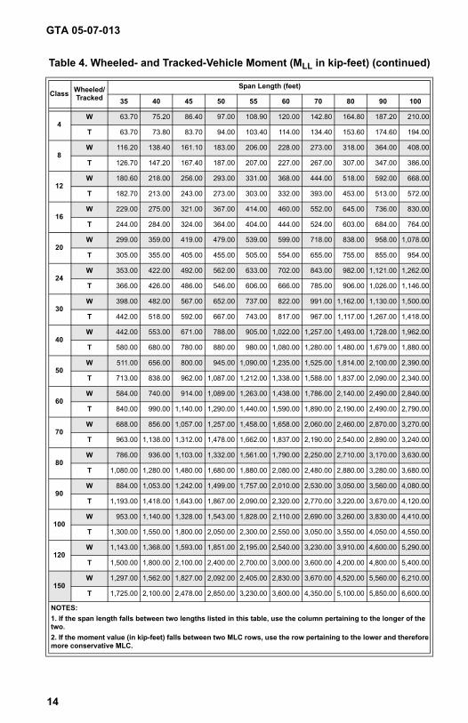
Table 4. Wheeled- and Tracked-Vehicle Moment (MLL in kip-feet) (continued)
Class Wheeled/Tracked
Span Length (feet)
35 40 45 50 55 60 70 80 90 100
4W 63.70 75.20 86.40 97.00 108.90 120.00 142.80 164.80 187.20 210.00
T 63.70 73.80 83.70 94.00 103.40 114.00 134.40 153.60 174.60 194.00
8W 116.20 138.40 161.10 183.00 206.00 228.00 273.00 318.00 364.00 408.00
T 126.70 147.20 167.40 187.00 207.00 227.00 267.00 307.00 347.00 386.00
12W 180.60 218.00 256.00 293.00 331.00 368.00 444.00 518.00 592.00 668.00
T 182.70 213.00 243.00 273.00 303.00 332.00 393.00 453.00 513.00 572.00
16W 229.00 275.00 321.00 367.00 414.00 460.00 552.00 645.00 736.00 830.00
T 244.00 284.00 324.00 364.00 404.00 444.00 524.00 603.00 684.00 764.00
20W 299.00 359.00 419.00 479.00 539.00 599.00 718.00 838.00 958.00 1,078.00
T 305.00 355.00 405.00 455.00 505.00 554.00 655.00 755.00 855.00 954.00
24W 353.00 422.00 492.00 562.00 633.00 702.00 843.00 982.00 1,121.00 1,262.00
T 366.00 426.00 486.00 546.00 606.00 666.00 785.00 906.00 1,026.00 1,146.00
30W 398.00 482.00 567.00 652.00 737.00 822.00 991.00 1,162.00 1,130.00 1,500.00
T 442.00 518.00 592.00 667.00 743.00 817.00 967.00 1,117.00 1,267.00 1,418.00
40W 442.00 553.00 671.00 788.00 905.00 1,022.00 1,257.00 1,493.00 1,728.00 1,962.00
T 580.00 680.00 780.00 880.00 980.00 1,080.00 1,280.00 1,480.00 1,679.00 1,880.00
50W 511.00 656.00 800.00 945.00 1,090.00 1,235.00 1,525.00 1,814.00 2,100.00 2,390.00
T 713.00 838.00 962.00 1,087.00 1,212.00 1,338.00 1,588.00 1,837.00 2,090.00 2,340.00
60W 584.00 740.00 914.00 1,089.00 1,263.00 1,438.00 1,786.00 2,140.00 2,490.00 2,840.00
T 840.00 990.00 1,140.00 1,290.00 1,440.00 1,590.00 1,890.00 2,190.00 2,490.00 2,790.00
70W 688.00 856.00 1,057.00 1,257.00 1,458.00 1,658.00 2,060.00 2,460.00 2,870.00 3,270.00
T 963.00 1,138.00 1,312.00 1,478.00 1,662.00 1,837.00 2,190.00 2,540.00 2,890.00 3,240.00
80W 786.00 936.00 1,103.00 1,332.00 1,561.00 1,790.00 2,250.00 2,710.00 3,170.00 3,630.00
T 1,080.00 1,280.00 1,480.00 1,680.00 1,880.00 2,080.00 2,480.00 2,880.00 3,280.00 3,680.00
90W 884.00 1,053.00 1,242.00 1,499.00 1,757.00 2,010.00 2,530.00 3,050.00 3,560.00 4,080.00
T 1,193.00 1,418.00 1,643.00 1,867.00 2,090.00 2,320.00 2,770.00 3,220.00 3,670.00 4,120.00
100W 953.00 1,140.00 1,328.00 1,543.00 1,828.00 2,110.00 2,690.00 3,260.00 3,830.00 4,410.00
T 1,300.00 1,550.00 1,800.00 2,050.00 2,300.00 2,550.00 3,050.00 3,550.00 4,050.00 4,550.00
120W 1,143.00 1,368.00 1,593.00 1,851.00 2,195.00 2,540.00 3,230.00 3,910.00 4,600.00 5,290.00
T 1,500.00 1,800.00 2,100.00 2,400.00 2,700.00 3,000.00 3,600.00 4,200.00 4,800.00 5,400.00
150W 1,297.00 1,562.00 1,827.00 2,092.00 2,405.00 2,830.00 3,670.00 4,520.00 5,560.00 6,210.00
T 1,725.00 2,100.00 2,478.00 2,850.00 3,230.00 3,600.00 4,350.00 5,100.00 5,850.00 6,600.00
GTA 05-07-013
14
NOTES:1. If the span length falls between two lengths listed in this table, use the column pertaining to the longer of the two.2. If the moment value (in kip-feet) falls between two MLC rows, use the row pertaining to the lower and therefore more conservative MLC.
new05-07-013.pdf 14 6/14/2006 11:48:56 AMnew05-07-013.pdf 14 6/14/2006 12:31:18 PM
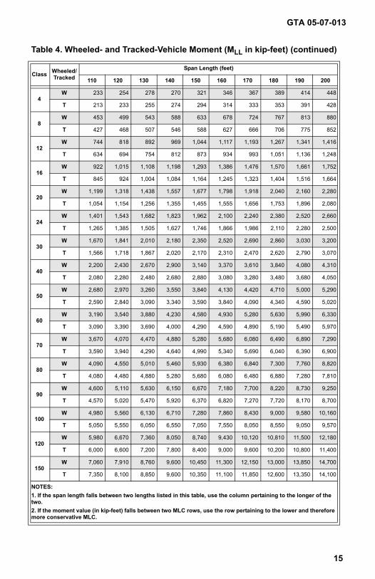
Table 4. Wheeled- and Tracked-Vehicle Moment (MLL in kip-feet) (continued)
Class Wheeled/Tracked
Span Length (feet)
110 120 130 140 150 160 170 180 190 200
4W 233 254 278 270 321 346 367 389 414 448
T 213 233 255 274 294 314 333 353 391 428
8W 453 499 543 588 633 678 724 767 813 880
T 427 468 507 546 588 627 666 706 775 852
12W 744 818 892 969 1,044 1,117 1,193 1,267 1,341 1,416
T 634 694 754 812 873 934 993 1,051 1,136 1,248
16W 922 1,015 1,108 1,198 1,293 1,386 1,476 1,570 1,661 1,752
T 845 924 1,004 1,084 1,164 1,245 1,323 1,404 1,516 1,664
20W 1,199 1,318 1,438 1,557 1,677 1,798 1,918 2,040 2,160 2,280
T 1,054 1,154 1,256 1,355 1,455 1,555 1,656 1,753 1,896 2,080
24W 1,401 1,543 1,682 1,823 1,962 2,100 2,240 2,380 2,520 2,660
T 1,265 1,385 1,505 1,627 1,746 1,866 1,986 2,110 2,280 2,500
30W 1,670 1,841 2,010 2,180 2,350 2,520 2,690 2,860 3,030 3,200
T 1,566 1,718 1,867 2,020 2,170 2,310 2,470 2,620 2,790 3,070
40W 2,200 2,430 2,670 2,900 3,140 3,370 3,610 3,840 4,080 4,310
T 2,080 2,280 2,480 2,680 2,880 3,080 3,280 3,480 3,680 4,050
50W 2,680 2,970 3,260 3,550 3,840 4,130 4,420 4,710 5,000 5,290
T 2,590 2,840 3,090 3,340 3,590 3,840 4,090 4,340 4,590 5,020
60W 3,190 3,540 3,880 4,230 4,580 4,930 5,280 5,630 5,990 6,330
T 3,090 3,390 3,690 4,000 4,290 4,590 4,890 5,190 5,490 5,970
70W 3,670 4,070 4,470 4,880 5,280 5,680 6,080 6,490 6,890 7,290
T 3,590 3,940 4,290 4,640 4,990 5,340 5,690 6,040 6,390 6,900
80W 4,090 4,550 5,010 5,460 5,930 6,380 6,840 7,300 7,760 8,820
T 4,080 4,480 4,880 5,280 5,680 6,080 6,480 6,880 7,280 7,810
90W 4,600 5,110 5,630 6,150 6,670 7,180 7,700 8,220 8,730 9,250
T 4,570 5,020 5,470 5,920 6,370 6,820 7,270 7,720 8,170 8,700
100W 4,980 5,560 6,130 6,710 7,280 7,860 8,430 9,000 9,580 10,160
T 5,050 5,550 6,050 6,550 7,050 7,550 8,050 8,550 9,050 9,570
120W 5,980 6,670 7,360 8,050 8,740 9,430 10,120 10,810 11,500 12,180
T 6,000 6,600 7,200 7,800 8,400 9,000 9,600 10,200 10,800 11,400
150W 7,060 7,910 8,760 9,600 10,450 11,300 12,150 13,000 13,850 14,700
T 7,350 8,100 8,850 9,600 10,350 11,100 11,850 12,600 13,350 14,100
GTA 05-07-013
15
NOTES:1. If the span length falls between two lengths listed in this table, use the column pertaining to the longer of the two.2. If the moment value (in kip-feet) falls between two MLC rows, use the row pertaining to the lower and therefore more conservative MLC.
new05-07-013.pdf 15 6/14/2006 11:48:56 AMnew05-07-013.pdf 15 6/14/2006 12:31:18 PM
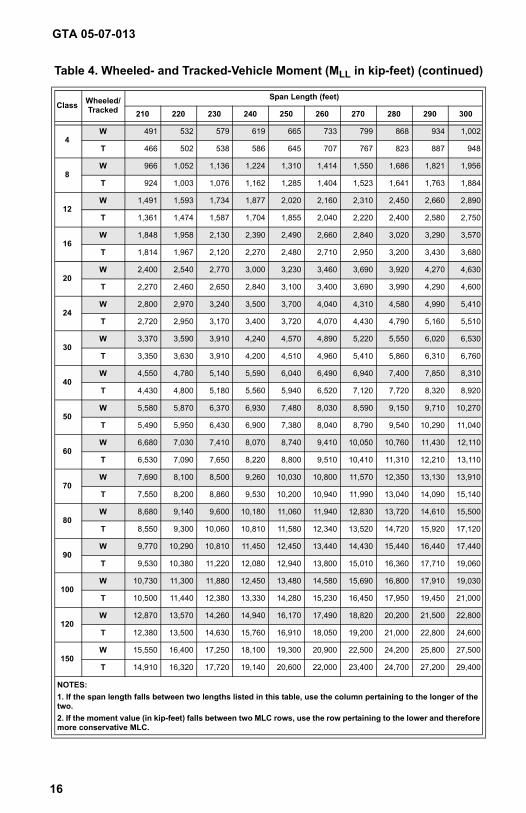
Table 4. Wheeled- and Tracked-Vehicle Moment (MLL in kip-feet) (continued)
Class Wheeled/Tracked
Span Length (feet)
210 220 230 240 250 260 270 280 290 300
4W 491 532 579 619 665 733 799 868 934 1,002
T 466 502 538 586 645 707 767 823 887 948
8W 966 1,052 1,136 1,224 1,310 1,414 1,550 1,686 1,821 1,956
T 924 1,003 1,076 1,162 1,285 1,404 1,523 1,641 1,763 1,884
12W 1,491 1,593 1,734 1,877 2,020 2,160 2,310 2,450 2,660 2,890
T 1,361 1,474 1,587 1,704 1,855 2,040 2,220 2,400 2,580 2,750
16W 1,848 1,958 2,130 2,390 2,490 2,660 2,840 3,020 3,290 3,570
T 1,814 1,967 2,120 2,270 2,480 2,710 2,950 3,200 3,430 3,680
20W 2,400 2,540 2,770 3,000 3,230 3,460 3,690 3,920 4,270 4,630
T 2,270 2,460 2,650 2,840 3,100 3,400 3,690 3,990 4,290 4,600
24W 2,800 2,970 3,240 3,500 3,700 4,040 4,310 4,580 4,990 5,410
T 2,720 2,950 3,170 3,400 3,720 4,070 4,430 4,790 5,160 5,510
30W 3,370 3,590 3,910 4,240 4,570 4,890 5,220 5,550 6,020 6,530
T 3,350 3,630 3,910 4,200 4,510 4,960 5,410 5,860 6,310 6,760
40W 4,550 4,780 5,140 5,590 6,040 6,490 6,940 7,400 7,850 8,310
T 4,430 4,800 5,180 5,560 5,940 6,520 7,120 7,720 8,320 8,920
50W 5,580 5,870 6,370 6,930 7,480 8,030 8,590 9,150 9,710 10,270
T 5,490 5,950 6,430 6,900 7,380 8,040 8,790 9,540 10,290 11,040
60W 6,680 7,030 7,410 8,070 8,740 9,410 10,050 10,760 11,430 12,110
T 6,530 7,090 7,650 8,220 8,800 9,510 10,410 11,310 12,210 13,110
70W 7,690 8,100 8,500 9,260 10,030 10,800 11,570 12,350 13,130 13,910
T 7,550 8,200 8,860 9,530 10,200 10,940 11,990 13,040 14,090 15,140
80W 8,680 9,140 9,600 10,180 11,060 11,940 12,830 13,720 14,610 15,500
T 8,550 9,300 10,060 10,810 11,580 12,340 13,520 14,720 15,920 17,120
90W 9,770 10,290 10,810 11,450 12,450 13,440 14,430 15,440 16,440 17,440
T 9,530 10,380 11,220 12,080 12,940 13,800 15,010 16,360 17,710 19,060
100W 10,730 11,300 11,880 12,450 13,480 14,580 15,690 16,800 17,910 19,030
T 10,500 11,440 12,380 13,330 14,280 15,230 16,450 17,950 19,450 21,000
120W 12,870 13,570 14,260 14,940 16,170 17,490 18,820 20,200 21,500 22,800
T 12,380 13,500 14,630 15,760 16,910 18,050 19,200 21,000 22,800 24,600
150W 15,550 16,400 17,250 18,100 19,300 20,900 22,500 24,200 25,800 27,500
T 14,910 16,320 17,720 19,140 20,600 22,000 23,400 24,700 27,200 29,400
GTA 05-07-013
16
NOTES:1. If the span length falls between two lengths listed in this table, use the column pertaining to the longer of the two.2. If the moment value (in kip-feet) falls between two MLC rows, use the row pertaining to the lower and therefore more conservative MLC.
new05-07-013.pdf 16 6/14/2006 11:48:56 AMnew05-07-013.pdf 16 6/14/2006 12:31:18 PM
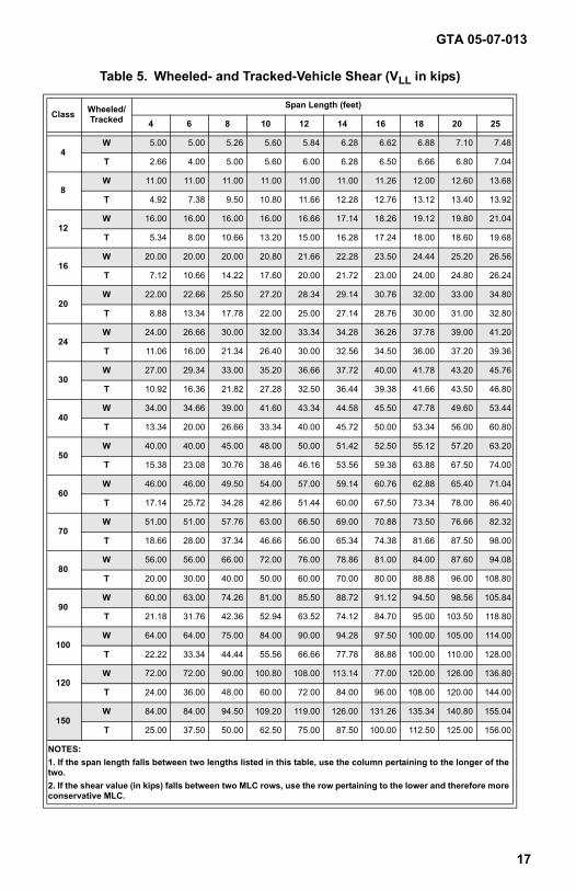
Table 5. Wheeled- and Tracked-Vehicle Shear (VLL in kips)
Class Wheeled/Tracked
Span Length (feet)
4 6 8 10 12 14 16 18 20 25
4W 5.00 5.00 5.26 5.60 5.84 6.28 6.62 6.88 7.10 7.48
T 2.66 4.00 5.00 5.60 6.00 6.28 6.50 6.66 6.80 7.04
8W 11.00 11.00 11.00 11.00 11.00 11.00 11.26 12.00 12.60 13.68
T 4.92 7.38 9.50 10.80 11.66 12.28 12.76 13.12 13.40 13.92
12W 16.00 16.00 16.00 16.00 16.66 17.14 18.26 19.12 19.80 21.04
T 5.34 8.00 10.66 13.20 15.00 16.28 17.24 18.00 18.60 19.68
16W 20.00 20.00 20.00 20.80 21.66 22.28 23.50 24.44 25.20 26.56
T 7.12 10.66 14.22 17.60 20.00 21.72 23.00 24.00 24.80 26.24
20W 22.00 22.66 25.50 27.20 28.34 29.14 30.76 32.00 33.00 34.80
T 8.88 13.34 17.78 22.00 25.00 27.14 28.76 30.00 31.00 32.80
24W 24.00 26.66 30.00 32.00 33.34 34.28 36.26 37.78 39.00 41.20
T 11.06 16.00 21.34 26.40 30.00 32.56 34.50 36.00 37.20 39.36
30W 27.00 29.34 33.00 35.20 36.66 37.72 40.00 41.78 43.20 45.76
T 10.92 16.36 21.82 27.28 32.50 36.44 39.38 41.66 43.50 46.80
40W 34.00 34.66 39.00 41.60 43.34 44.58 45.50 47.78 49.60 53.44
T 13.34 20.00 26.66 33.34 40.00 45.72 50.00 53.34 56.00 60.80
50W 40.00 40.00 45.00 48.00 50.00 51.42 52.50 55.12 57.20 63.20
T 15.38 23.08 30.76 38.46 46.16 53.56 59.38 63.88 67.50 74.00
60W 46.00 46.00 49.50 54.00 57.00 59.14 60.76 62.88 65.40 71.04
T 17.14 25.72 34.28 42.86 51.44 60.00 67.50 73.34 78.00 86.40
70W 51.00 51.00 57.76 63.00 66.50 69.00 70.88 73.50 76.66 82.32
T 18.66 28.00 37.34 46.66 56.00 65.34 74.38 81.66 87.50 98.00
80W 56.00 56.00 66.00 72.00 76.00 78.86 81.00 84.00 87.60 94.08
T 20.00 30.00 40.00 50.00 60.00 70.00 80.00 88.88 96.00 108.80
90W 60.00 63.00 74.26 81.00 85.50 88.72 91.12 94.50 98.56 105.84
T 21.18 31.76 42.36 52.94 63.52 74.12 84.70 95.00 103.50 118.80
100W 64.00 64.00 75.00 84.00 90.00 94.28 97.50 100.00 105.00 114.00
T 22.22 33.34 44.44 55.56 66.66 77.78 88.88 100.00 110.00 128.00
120W 72.00 72.00 90.00 100.80 108.00 113.14 77.00 120.00 126.00 136.80
T 24.00 36.00 48.00 60.00 72.00 84.00 96.00 108.00 120.00 144.00
150W 84.00 84.00 94.50 109.20 119.00 126.00 131.26 135.34 140.80 155.04
T 25.00 37.50 50.00 62.50 75.00 87.50 100.00 112.50 125.00 156.00
GTA 05-07-013
17
NOTES:1. If the span length falls between two lengths listed in this table, use the column pertaining to the longer of the two.2. If the shear value (in kips) falls between two MLC rows, use the row pertaining to the lower and therefore more conservative MLC.
new05-07-013.pdf 17 6/14/2006 11:48:56 AMnew05-07-013.pdf 17 6/14/2006 12:31:19 PM
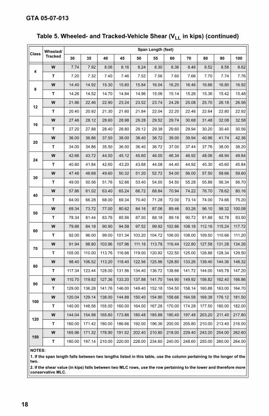
Table 5. Wheeled- and Tracked-Vehicle Shear (VLL in kips) (continued)
Class Wheeled/Tracked
Span Length (feet)
30 35 40 45 50 55 60 70 80 90 100
4W 7.74 7.92 8.06 8.16 8.24 8.30 8.36 8.46 8.52 8.58 8.62
T 7.20 7.32 7.40 7.46 7.52 7.56 7.60 7.66 7.70 7.74 7.76
8W 14.40 14.92 15.30 15.60 15.84 16.04 16.20 16.46 16.66 16.80 16.92
T 14.26 14.52 14.70 14.84 14.96 15.06 15.14 15.26 15.36 15.42 15.48
12W 21.86 22.46 22.90 23.24 23.52 23.74 24.26 25.08 25.70 26.18 26.56
T 20.40 20.92 21.30 21.60 21.84 22.04 22.20 22.46 22.64 22.80 22.92
16W 27.46 28.12 28.60 28.98 29.28 29.52 29.74 30.68 31.48 32.08 32.58
T 27.20 27.88 28.40 28.80 29.12 29.38 29.60 29.94 30.20 30.40 30.56
20W 36.00 36.86 37.50 38.00 38.40 38.72 39.00 39.94 40.96 41.74 42.36
T 34.00 34.86 35.50 36.00 36.40 36.72 37.00 37.44 37.76 38.00 38.20
24W 42.66 43.72 44.50 45.12 45.60 46.00 46.34 46.92 48.06 48.94 49.64
T 40.80 41.84 42.60 43.20 43.68 44.08 44.40 44.92 45.30 45.60 45.84
30W 47.46 48.68 49.60 50.32 51.20 52.72 54.00 56.00 57.50 58.66 59.60
T 49.00 50.56 51.76 52.66 53.40 54.00 54.50 55.28 55.88 56.34 56.70
40W 57.86 61.02 63.40 65.24 66.72 68.84 70.94 74.22 76.70 78.62 80.16
T 64.00 66.28 68.00 69.34 70.40 71.28 72.00 73.14 74.00 74.66 75.20
50W 69.34 73.72 77.00 80.62 84.16 87.06 89.46 93.26 96.10 98.32 100.08
T 78.34 81.44 83.76 85.56 87.00 88.18 89.16 90.72 91.88 92.78 93.50
60W 79.86 84.18 90.90 94.58 97.52 99.92 102.86 108.18 112.16 115.24 117.72
T 92.00 96.00 99.00 101.34 103.20 104.72 106.00 108.00 109.50 110.66 111.20
70W 91.94 98.80 103.96 107.96 111.16 113.78 116.44 122.80 127.58 131.28 134.26
T 105.00 110.00 113.76 116.66 119.00 120.92 122.50 125.00 126.88 128.34 129.50
80W 98.40 106.52 113.20 118.40 122.56 125.96 128.80 133.26 139.40 144.36 148.32
T 117.34 123.44 128.00 131.56 134.40 136.72 138.66 141.72 144.00 145.78 147.20
90W 110.70 119.82 127.36 133.20 137.88 141.70 144.90 149.92 156.82 162.40 166.86
T 129.00 136.28 141.76 146.00 149.40 152.18 154.50 158.14 160.88 163.00 164.70
100W 120.04 129.14 138.00 144.88 150.40 154.90 158.66 164.58 169.38 176.12 181.50
T 140.00 148.56 155.00 160.00 164.00 167.28 170.00 174.28 177.50 180.00 182.00
120W 144.04 154.98 165.60 173.86 180.48 185.88 190.40 197.48 203.20 211.40 217.80
T 160.00 171.42 180.00 186.66 192.00 196.36 200.00 205.80 210.00 213.40 216.00
150W 165.96 171.32 178.90 191.52 202.40 210.80 218.00 229.40 243.20 254.00 262.60
T 180.00 197.14 210.00 220.00 228.00 234.60 240.00 248.60 255.00 260.00 264.00
GTA 05-07-013
18
NOTES:1. If the span length falls between two lengths listed in this table, use the column pertaining to the longer of the two.2. If the shear value (in kips) falls between two MLC rows, use the row pertaining to the lower and therefore more conservative MLC.
new05-07-013.pdf 18 6/14/2006 11:48:56 AMnew05-07-013.pdf 18 6/14/2006 12:31:19 PM
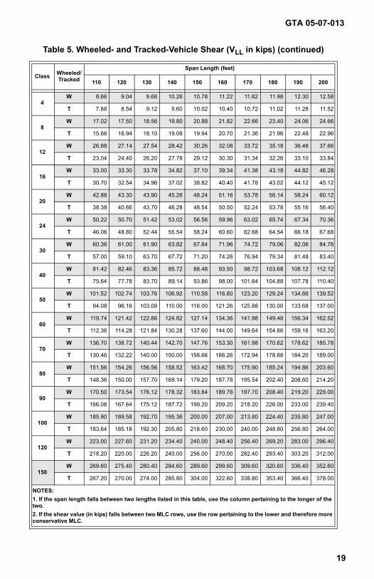
Table 5. Wheeled- and Tracked-Vehicle Shear (VLL in kips) (continued)
Class Wheeled/Tracked
Span Length (feet)
110 120 130 140 150 160 170 180 190 200
4W 8.66 9.04 9.66 10.26 10.78 11.22 11.62 11.98 12.30 12.58
T 7.88 8.54 9.12 9.60 10.02 10.40 10.72 11.02 11.28 11.52
8W 17.02 17.50 18.56 19.80 20.88 21.82 22.66 23.40 24.06 24.66
T 15.66 16.94 18.10 19.08 19.94 20.70 21.36 21.96 22.48 22.96
12W 26.88 27.14 27.54 28.42 30.26 32.08 33.72 35.18 36.48 37.66
T 23.04 24.40 26.20 27.78 29.12 30.30 31.34 32.26 33.10 33.84
16W 33.00 33.30 33.78 34.82 37.10 39.34 41.38 43.18 44.82 46.28
T 30.70 32.54 34.96 37.02 38.82 40.40 41.78 43.02 44.12 45.12
20W 42.88 43.30 43.90 45.26 48.24 51.16 53.78 56.14 58.24 60.12
T 38.38 40.66 43.70 46.28 48.54 50.50 52.24 53.78 55.16 56.40
24W 50.22 50.70 51.42 53.02 56.56 59.96 63.02 65.74 67.34 70.36
T 46.06 48.80 52.44 55.54 58.24 60.60 62.68 64.54 66.18 67.68
30W 60.36 61.00 61.90 63.82 67.84 71.96 74.72 79.06 82.06 84.76
T 57.00 59.10 63.70 67.72 71.20 74.26 76.94 79.34 81.48 83.40
40W 81.42 82.46 83.36 85.72 88.48 93.50 98.72 103.68 108.12 112.12
T 75.64 77.78 83.70 89.14 93.86 98.00 101.64 104.88 107.78 110.40
50W 101.52 102.74 103.76 106.92 110.58 116.80 123.20 129.24 134.66 139.52
T 94.08 96.16 103.08 110.00 116.00 121.26 125.88 130.00 133.68 137.00
60W 119.74 121.42 122.86 124.82 127.14 134.36 141.98 149.48 156.34 162.52
T 112.36 114.28 121.84 130.28 137.60 144.00 149.64 154.66 159.16 163.20
70W 136.70 138.72 140.44 142.70 147.76 153.30 161.98 170.62 178.62 185.78
T 130.46 132.22 140.00 150.00 158.66 166.26 172.94 178.88 184.20 189.00
80W 151.56 154.26 156.56 158.52 163.42 168.70 175.90 185.24 194.86 203.60
T 148.36 150.00 157.70 169.14 179.20 187.78 195.54 202.40 208.60 214.20
90W 170.50 173.54 176.12 178.32 183.84 189.78 197.70 208.40 219.20 229.00
T 166.08 167.64 175.12 187.72 199.20 209.20 218.20 226.00 233.00 239.40
100W 185.90 189.58 192.70 195.36 200.00 207.00 213.80 224.40 235.80 247.00
T 183.64 185.18 192.30 205.80 218.60 230.00 240.00 248.80 256.80 264.00
120W 223.00 227.60 231.20 234.40 240.00 248.40 256.40 269.20 283.00 296.40
T 218.20 220.00 226.20 240.00 256.00 270.00 282.40 293.40 303.20 312.00
150W 269.60 275.40 280.40 284.60 289.60 299.60 309.60 320.60 336.40 352.60
T 267.20 270.00 274.00 285.80 304.00 322.60 338.80 353.40 366.40 378.00
GTA 05-07-013
19
NOTES:1. If the span length falls between two lengths listed in this table, use the column pertaining to the longer of the two.2. If the shear value (in kips) falls between two MLC rows, use the row pertaining to the lower and therefore more conservative MLC.
new05-07-013.pdf 19 6/14/2006 11:48:56 AMnew05-07-013.pdf 19 6/14/2006 12:31:19 PM
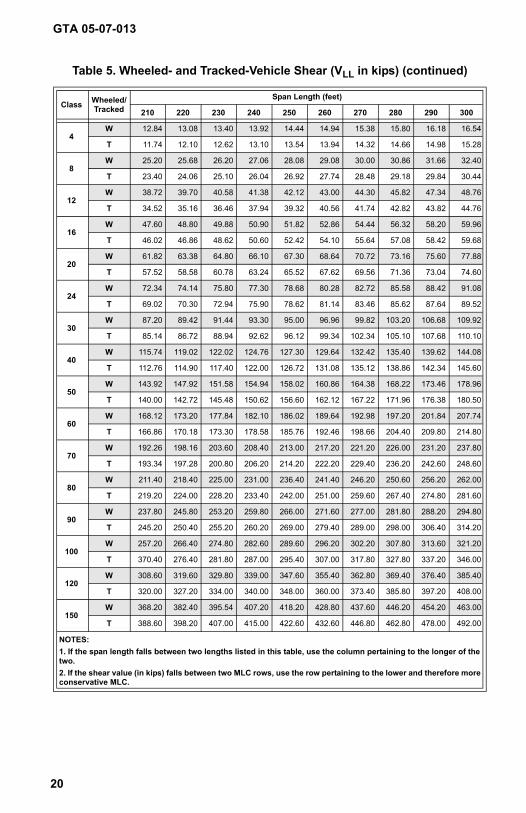
Table 5. Wheeled- and Tracked-Vehicle Shear (VLL in kips) (continued)
Class Wheeled/Tracked
Span Length (feet)
210 220 230 240 250 260 270 280 290 300
4W 12.84 13.08 13.40 13.92 14.44 14.94 15.38 15.80 16.18 16.54
T 11.74 12.10 12.62 13.10 13.54 13.94 14.32 14.66 14.98 15.28
8W 25.20 25.68 26.20 27.06 28.08 29.08 30.00 30.86 31.66 32.40
T 23.40 24.06 25.10 26.04 26.92 27.74 28.48 29.18 29.84 30.44
12W 38.72 39.70 40.58 41.38 42.12 43.00 44.30 45.82 47.34 48.76
T 34.52 35.16 36.46 37.94 39.32 40.56 41.74 42.82 43.82 44.76
16W 47.60 48.80 49.88 50.90 51.82 52.86 54.44 56.32 58.20 59.96
T 46.02 46.86 48.62 50.60 52.42 54.10 55.64 57.08 58.42 59.68
20W 61.82 63.38 64.80 66.10 67.30 68.64 70.72 73.16 75.60 77.88
T 57.52 58.58 60.78 63.24 65.52 67.62 69.56 71.36 73.04 74.60
24W 72.34 74.14 75.80 77.30 78.68 80.28 82.72 85.58 88.42 91.08
T 69.02 70.30 72.94 75.90 78.62 81.14 83.46 85.62 87.64 89.52
30W 87.20 89.42 91.44 93.30 95.00 96.96 99.82 103.20 106.68 109.92
T 85.14 86.72 88.94 92.62 96.12 99.34 102.34 105.10 107.68 110.10
40W 115.74 119.02 122.02 124.76 127.30 129.64 132.42 135.40 139.62 144.08
T 112.76 114.90 117.40 122.00 126.72 131.08 135.12 138.86 142.34 145.60
50W 143.92 147.92 151.58 154.94 158.02 160.86 164.38 168.22 173.46 178.96
T 140.00 142.72 145.48 150.62 156.60 162.12 167.22 171.96 176.38 180.50
60W 168.12 173.20 177.84 182.10 186.02 189.64 192.98 197.20 201.84 207.74
T 166.86 170.18 173.30 178.58 185.76 192.46 198.66 204.40 209.80 214.80
70W 192.26 198.16 203.60 208.40 213.00 217.20 221.20 226.00 231.20 237.80
T 193.34 197.28 200.80 206.20 214.20 222.20 229.40 236.20 242.60 248.60
80W 211.40 218.40 225.00 231.00 236.40 241.40 246.20 250.60 256.20 262.00
T 219.20 224.00 228.20 233.40 242.00 251.00 259.60 267.40 274.80 281.60
90W 237.80 245.80 253.20 259.80 266.00 271.60 277.00 281.80 288.20 294.80
T 245.20 250.40 255.20 260.20 269.00 279.40 289.00 298.00 306.40 314.20
100W 257.20 266.40 274.80 282.60 289.60 296.20 302.20 307.80 313.60 321.20
T 370.40 276.40 281.80 287.00 295.40 307.00 317.80 327.80 337.20 346.00
120W 308.60 319.60 329.80 339.00 347.60 355.40 362.80 369.40 376.40 385.40
T 320.00 327.20 334.00 340.00 348.00 360.00 373.40 385.80 397.20 408.00
150W 368.20 382.40 395.54 407.20 418.20 428.80 437.60 446.20 454.20 463.00
T 388.60 398.20 407.00 415.00 422.60 432.60 446.80 462.80 478.00 492.00
GTA 05-07-013
20
NOTES:1. If the span length falls between two lengths listed in this table, use the column pertaining to the longer of the two.2. If the shear value (in kips) falls between two MLC rows, use the row pertaining to the lower and therefore more conservative MLC.
new05-07-013.pdf 20 6/14/2006 11:48:56 AMnew05-07-013.pdf 20 6/14/2006 12:31:19 PM
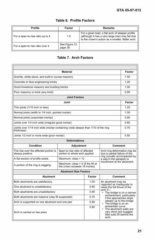
Table 6. Profile Factors
Profile Factor Remarks
For a span-to-rise ratio up to 4 1.0For a given load, a flat arch of steeper profile (although it has a very large rise) may fail due to the crown’s action as a smaller, flatter arch.
For a span-to rise ratio over 4 See Figure 13, page 26.
Table 7. Arch Factors
Material Factors
Material Factor
Granite, white stone, and built-in course masonry 1.50
Concrete or blue engineering bricks 1.20
Good limestone masonry and building blocks 1.00
Poor masonry or brick (any kind) 0.50
Joint Factors
Joint Factor
Thin joints (1/10 inch or less) 1.25
Normal joints (width to 1/4 inch, pointed mortar) 1.00
Normal joints (unpointed mortar) 0.90
Joints over 1/4 inch wide (irregular good mortar) 0.80
Joints over 1/14 inch wide (mortar containing voids deeper than 1/10 of the ring thickness)
0.70
Joints 1/2 inch or more wide (poor mortar) 0.50
Deformations
Condition Adjustment Comment
The rise over the affected portion is always positive
Span-to-rise ratio of affected portion to whole arch applied
Arch ring deformation may be due to partial failure of the ring (usually accompanied by a sag in the parapet) or movement at the abutment.
A flat section of profile exists Maximum: class = 12
A portion of the ring is sagging Maximum: class = 5 (if the fill at the crown exceeds 18 inches)
Abutment Size Factors
Abutment Factor Comment
Both abutments are satisfactory 1.00 An abutment may be regarded as inadequate to resist the full thrust of the arch if—• The bridge is on a narrow
embankment, particularly if the approaches slope steeply up to the bridge.
• The bridge is on an embanked curve.
• The abutment walls are very short and suggest little solid fill behind the arch.
One abutment is unsatisfactory 0.95
Both abutments are unsatisfactory 0.90
Both abutments are massive (clay fill suspected) 0.70
Arch is supported on one abutment and one pier 0.90
Arch is carried on two piers
0.80
GTA 05-07-013
21
new05-07-013.pdf 21 6/14/2006 11:48:57 AMnew05-07-013.pdf 21 6/14/2006 12:31:19 PM
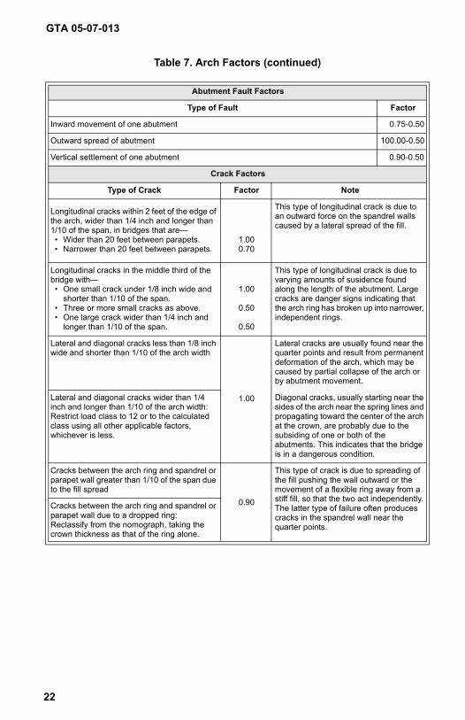
Table 7. Arch Factors (continued)
Abutment Fault Factors
Type of Fault Factor
Inward movement of one abutment 0 .75-0.50
Outward spread of abutment 1 00.00-0.50
Vertical settlement of one abutment 0.90-0 .50
Crack Factors
Type of Crack Factor Note
Longitudinal cracks within 2 feet of the edge of the arch, wider than 1/4 inch and longer than 1/10 of the span, in bridges that are—• Wider than 20 feet between parapets.• Narrower than 20 feet between parapets.
1.000.70
This type of longitudinal crack is due to an outward force on the spandrel walls caused by a lateral spread of the fill.
Longitudinal cracks in the middle third of the bridge with—• One small crack under 1/8 inch wide and
shorter than 1/10 of the span.• Three or more small cracks as above.• One large crack wider than 1/4 inch and
longer than 1/10 of the span.
1.00
0.50
0.50
This type of longitudinal crack is due to varying amounts of susidence found along the length of the abutment. Large cracks are danger signs indicating that the arch ring has broken up into narrower, independent rings.
Lateral and diagonal cracks less than 1/8 inch wide and shorter than 1/10 of the arch width
1.00
Lateral cracks are usually found near the quarter points and result from permanent deformation of the arch, which may be caused by partial collapse of the arch or by abutment movement.
Lateral and diagonal cracks wider than 1/4 inch and longer than 1/10 of the arch width: Restrict load class to 12 or to the calculated class using all other applicable factors, whichever is less.
Diagonal cracks, usually starting near the sides of the arch near the spring lines and propagating toward the center of the arch at the crown, are probably due to the subsiding of one or both of the abutments. This indicates that the bridge is in a dangerous condition.
Cracks between the arch ring and spandrel or parapet wall greater than 1/10 of the span due to the fill spread
0.90
This type of crack is due to spreading of the fill pushing the wall outward or the movement of a flexible ring away from a stiff fill, so that the two act independently. The latter type of failure often produces cracks in the spandrel wall near the quarter points.
Cracks between the arch ring and spandrel or parapet wall due to a dropped ring: Reclassify from the nomograph, taking the crown thickness as that of the ring alone.
GTA 05-07-013
22
new05-07-013.pdf 22 6/14/2006 11:48:57 AMnew05-07-013.pdf 22 6/14/2006 12:31:19 PM
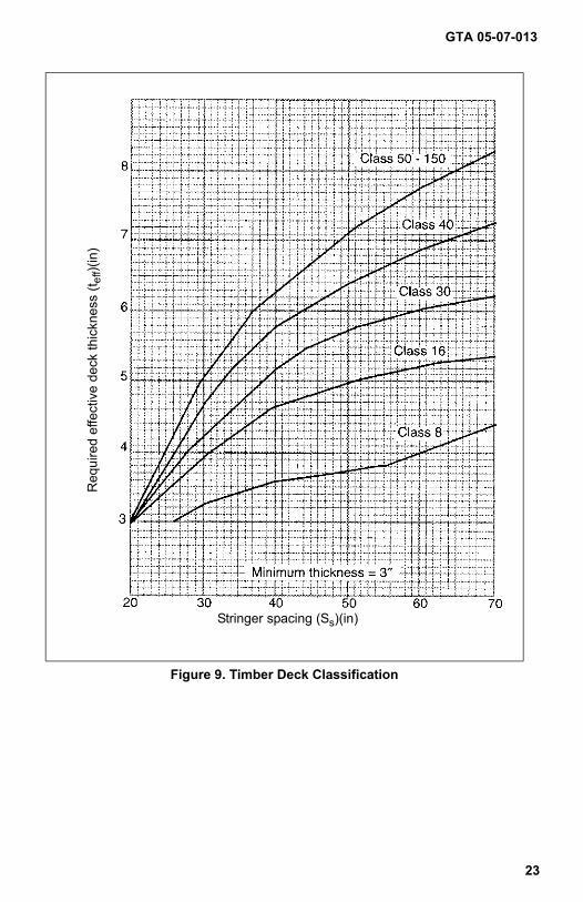
Figure 9. Timber Deck Classification
Stringer spacing (Ss)(in)
Req
uire
d ef
fect
ive
deck
thic
knes
s (t e
ff)(in
)
GTA 05-07-013
23
new05-07-013.pdf 23 6/14/2006 11:48:57 AMnew05-07-013.pdf 23 6/14/2006 12:31:19 PM
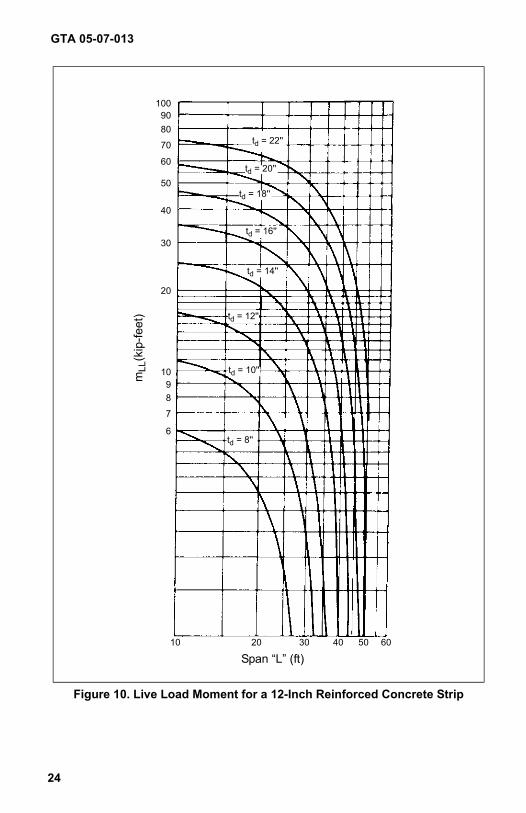
Figure 10. Live Load Moment for a 12-Inch Reinforced Concrete Strip
mLL
(kip
-feet
)
Span “L” (ft)
td = 22''
td = 20''
td = 18''
td = 16''
td = 14''
td = 12''
td = 10''
td = 8''
1009080
70
60
50
40
30
20
1098
7
6
10 20 30 40 50 60
GTA 05-07-013
24
new05-07-013.pdf 24 6/14/2006 11:48:57 AMnew05-07-013.pdf 24 6/14/2006 12:31:19 PM
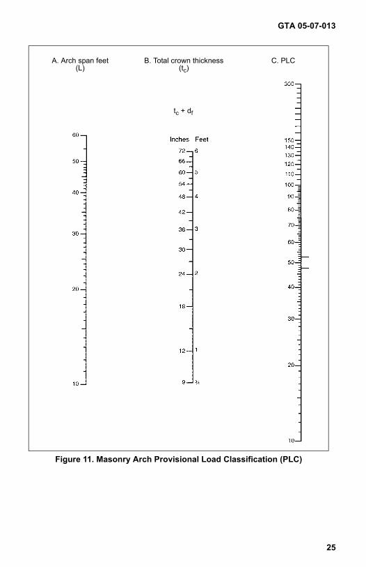
Figure 11. Masonry Arch Provisional Load Classification (PLC)
A. Arch span feet(L)
B. Total crown thickness(tc)
C. PLC
tc + df
GTA 05-07-013
25
new05-07-013.pdf 25 6/14/2006 11:48:57 AMnew05-07-013.pdf 25 6/14/2006 12:31:19 PM
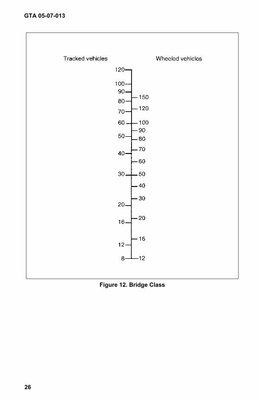
Figure 12. Bridge Class
GTA 05-07-013
26
new05-07-013.pdf 26 6/14/2006 11:48:57 AMnew05-07-013.pdf 26 6/14/2006 12:31:20 PM
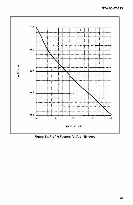
Figure 13. Profile Factors for Arch Bridges
GTA 05-07-013
27
new05-07-013.pdf 27 6/14/2006 11:48:57 AMnew05-07-013.pdf 27 6/14/2006 12:31:20 PM
GTA 05-07-013
28
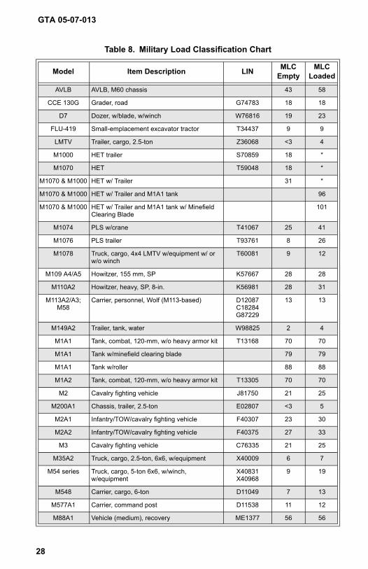
Table 8. Military Load Classification Chart
Model Item Description LIN MLC Empty
MLC Loaded
AVLB AVLB, M60 chassis 43 58
CCE 130G Grader, road G74783 18 18
D7 Dozer, w/blade, w/winch W76816 19 23
FLU-419 Small-emplacement excavator tractor T34437 9 9
LMTV Trailer, cargo, 2.5-ton Z36068 <3 4
M1000 HET trailer S70859 18 *
M1070 HET T59048 18 *
M1070 & M1000 HET w/ Trailer 31 *
M1070 & M1000 HET w/ Trailer and M1A1 tank 96
M1070 & M1000 HET w/ Trailer and M1A1 tank w/ Minefield Clearing Blade
101
M1074 PLS w/crane T41067 25 41
M1076 PLS trailer T93761 8 26
M1078 Truck, cargo, 4x4 LMTV w/equipment w/ or w/o winch
T60081 9 12
M109 A4/A5 Howitzer, 155 mm, SP K57667 28 28
M110A2 Howitzer, heavy, SP, 8-in. K56981 28 31
M113A2/A3; M58
Carrier, personnel, Wolf (M113-based) D12087C18284G87229
13 13
M149A2 Trailer, tank, water W98825 2 4
M1A1 Tank, combat, 120-mm, w/o heavy armor kit T13168 70 70
M1A1 Tank w/minefield clearing blade 79 79
M1A1 Tank w/roller 88 88
M1A2 Tank, combat, 120-mm, w/o heavy armor kit T13305 70 70
M2 Cavalry fighting vehicle J81750 21 25
M200A1 Chassis, trailer, 2.5-ton E02807 <3 5
M2A1 Infantry/TOW/cavalry fighting vehicle F40307 23 30
M2A2 Infantry/TOW/cavalry fighting vehicle F40375 27 33
M3 Cavalry fighting vehicle C76335 21 25
M35A2 Truck, cargo, 2.5-ton, 6x6, w/equipment X40009 6 7
M54 series Truck, cargo, 5-ton 6x6, w/winch, w/equipment
X40831X40968
9 19
M548 Carrier, cargo, 6-ton D11049 7 13
M577A1 Carrier, command post D11538 11 12
M88A1 Vehicle (medium), recovery ME1377 56 56
new05-07-013.pdf 28 6/14/2006 11:48:57 AMnew05-07-013.pdf 28 6/14/2006 12:31:20 PM
GTA 05-07-013
29
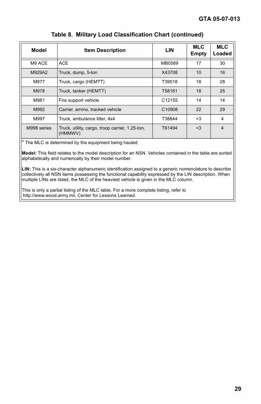
M9 ACE ACE MB0589 17 30
M929A2 Truck, dump, 5-ton X43708 10 16
M977 Truck, cargo (HEMTT) T39518 18 28
M978 Truck, tanker (HEMTT) T58161 18 25
M981 Fire support vehicle C12155 14 14
M992 Carrier, ammo, tracked vehicle C10908 22 29
M997 Truck, ambulance litter, 4x4 T38844 <3 4
M998 series Truck, utility, cargo, troop carrier, 1.25-ton, (HMMWV)
T61494 <3 4
* The MLC is determined by the equipment being hauled.
Model: This field relates to the model description for an NSN. Vehicles contained in the table are sorted alphabetically and numerically by their model number.
LIN: This is a six-character alphanumeric identification assigned to a generic nomenclature to describe collectively all NSN items possessing the functional capability expressed by the LIN description. When multiple LINs are listed, the MLC of the heaviest vehicle is given in the MLC column.
This is only a partial listing of the MLC table. For a more complete listing, refer to http://www.wood.army.mil, Center for Lessons Learned.
Table 8. Military Load Classification Chart (continued)
Model Item Description LIN MLC Empty
MLC Loaded
new05-07-013.pdf 29 6/14/2006 11:48:57 AMnew05-07-013.pdf 29 6/14/2006 12:31:20 PM


