

AASHTOWare BrD 6.8
Reinforced Concrete Structure Tutorial
RC8 - Reinforced Concrete Tee Beam Using BrD LRFD Engine

RC8 - Reinforced Concrete Tee Beam Using BrD LRFD Engine
Last Modified: 8/29/2016 1
30'-0"
4 spaces @ 6'-0" = 24'-0"
8" Including ½” integral wearing surface
26'-6" 1'-9"1'-9"
RC6 – Reinforced Concrete Tee Beam Using Opis LRFD Engine
Elevation
Typical Section
40'-0"
3'-0"3'-0"
6"6"
72"
3.064"
26" 40"
8" Total,
7 ½” Eff.
8-#9
#4 stirrups @ 12"
Jersey Barrier

RC8 - Reinforced Concrete Tee Beam Using BrD LRFD Engine
Last Modified: 8/29/2016 2
40'-0"
20'-0" 20'-0"4
sp
ace
s @
6'-0"
= 2
4'-0"
Framing Plan
Material Properties
Slab Concrete: Class A (US) f'c = 4.0 ksi, modular ratio n = 8
Slab Reinforcing Steel: AASHTO M31, Grade 60 with Fy = 60 ksi
Diaphragm weight = 1.2 kips/.each

RC8 - Reinforced Concrete Tee Beam Using BrD LRFD Engine
Last Modified: 8/29/2016 3
BrD Training
RC6 - Reinforced Concrete Tee Beam Using BrD LRFD Engine
Topics Covered
Reinforced concrete schedule based tee input as girder system.
Export of schedule based reinforced concrete beams to the BrD LRFD analysis engine
BrD LRFD specification checking
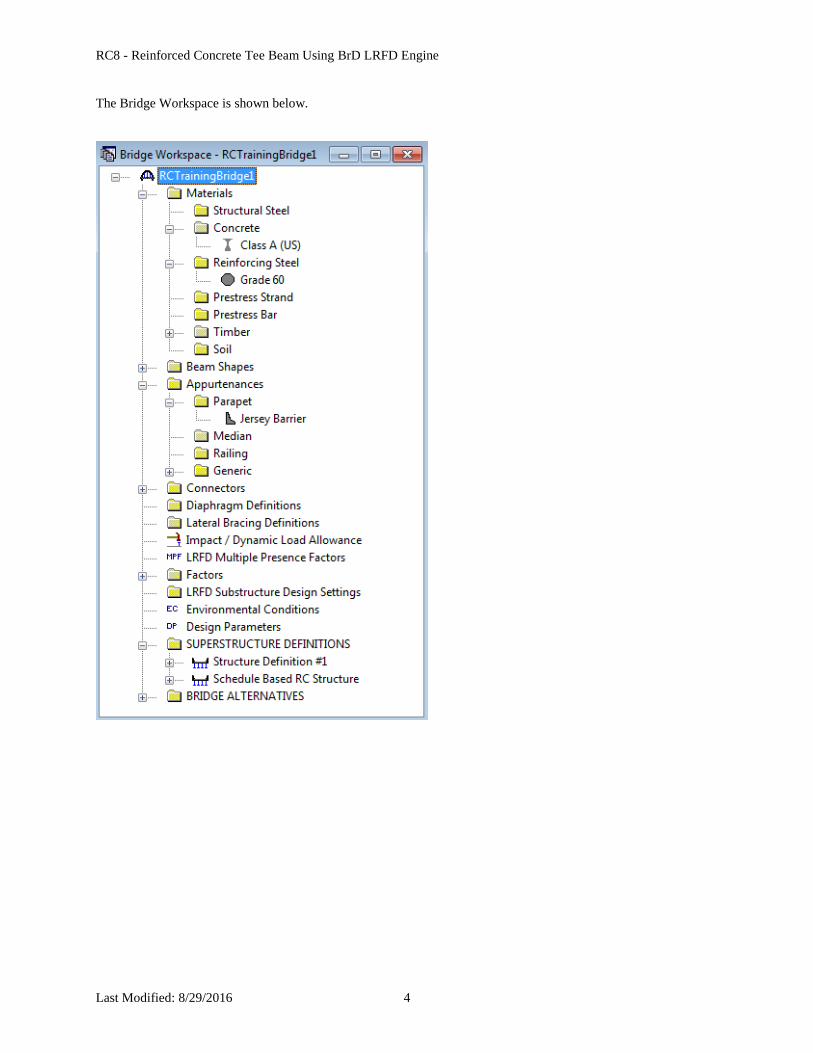
Open the Bridge Workspace for BID 11, “RCTrainingBridge1”.
RC8 - Reinforced Concrete Tee Beam Using BrD LRFD Engine
Last Modified: 8/29/2016 4
The Bridge Workspace is shown below.

RC8 - Reinforced Concrete Tee Beam Using BrD LRFD Engine
Last Modified: 8/29/2016 5
Double click on SUPERSTRUCTURE DEFINITIONS to create a new structure definition. The dialog shown
below will appear.

RC8 - Reinforced Concrete Tee Beam Using BrD LRFD Engine
Last Modified: 8/29/2016 6
Select Girder System and the Structure Definition window will open. Enter the appropriate data as shown below:

RC8 - Reinforced Concrete Tee Beam Using BrD LRFD Engine
Last Modified: 8/29/2016 7
Click Load Case Description to define the dead load cases. Use the “Add Default…” button to create the following
load cases.

RC8 - Reinforced Concrete Tee Beam Using BrD LRFD Engine
Last Modified: 8/29/2016 8
Double-click on Framing Plan Detail to describe the framing plan. Enter the appropriate data as shown below.

RC8 - Reinforced Concrete Tee Beam Using BrD LRFD Engine
Last Modified: 8/29/2016 9
Switch to the Diaphragms tab to enter diaphragm spacing. Enter the following diaphragms for Girder Bay 1 as
shown below:
Click the Copy Bay To button to copy the diaphragms entered for Bay to the other bays.
Click Apply to copy the diaphragms to girder bay 2.
Select Ok to close Structure Framing Plan Details window.

RC8 - Reinforced Concrete Tee Beam Using BrD LRFD Engine
Last Modified: 8/29/2016 10
Next define the structure typical section by double-clicking on Structure Typical Section in the Bridge Workspace
tree. Input the data describing the typical section as shown below. This screen initially shows steel girders as the
default girder type until the member alternatives are defined.
Basic deck geometry:

RC8 - Reinforced Concrete Tee Beam Using BrD LRFD Engine
Last Modified: 8/29/2016 11
The Deck (cont’d) tab is used to enter information about the deck concrete and thickness. The material to be used
for the deck concrete is selected from the list of bridge materials described above.

RC8 - Reinforced Concrete Tee Beam Using BrD LRFD Engine
Last Modified: 8/29/2016 12
Parapets:
The two parapets are described using the Parapet tab. Click New to add a row to the table. The name of the parapet
defaults to the only barrier described for the bridge. Change the “Load Case” to “DC2”. Reinforced concrete
structures only have 1 stage but we will select DC2 here since we want the dead load of the parapets to be uniformly
distributed to all girders and BrD only allows that type of load distribution in stage 2. We will discuss this more
when we review the Superstructure Loads window.
Change “Measure To” to “Back” (we are locating the parapet on the deck by referencing the back of the parapet to
the left edge of the deck). Enter 0.0 for the “Distance at Start” and “Distance at End”. Change the “Front Face
Orientation” to “Right”. The completed tab is shown below.

RC8 - Reinforced Concrete Tee Beam Using BrD LRFD Engine
Last Modified: 8/29/2016 13
Lane Positions:
Select the Lane Position tab. Enter the values shown below or click the “Compute…” button to automatically
compute the lane positions. A dialog showing the results of the computation opens. Click Apply to apply the
computed values. The Lane Position tab is populated as shown below.

RC8 - Reinforced Concrete Tee Beam Using BrD LRFD Engine
Last Modified: 8/29/2016 14
The schematic of the Structure Typical Section is shown below.

RC8 - Reinforced Concrete Tee Beam Using BrD LRFD Engine
Last Modified: 8/29/2016 15
The DL Distribution tab of the Superstructure Loads window is shown below. BrD only provides the “Uniformly to
all girders” distribution option for stage 2 dead loads. Even though reinforced concrete only has 1 stage, we
previously assigned our parapets to stage 2 on the Structure Typical Section window to take advantage of the
uniformly to all girders option. The export to the BrD LRFD analysis engine will uniformly distribute the parapets
to all girders and assign that load to the stage 1 model.

RC8 - Reinforced Concrete Tee Beam Using BrD LRFD Engine
Last Modified: 8/29/2016 16
Define shear reinforcement to be used by the girders. Expand the shear Reinforcement Definitions tree item and
double click on Vertical. Define the stirrup as shown below. Click Ok.

RC8 - Reinforced Concrete Tee Beam Using BrD LRFD Engine
Last Modified: 8/29/2016 17
Create the following Bar Mark Definition to be used for the longitudinal reinforcement in the beam.

RC8 - Reinforced Concrete Tee Beam Using BrD LRFD Engine
Last Modified: 8/29/2016 18
Describing member G2:
The member window shows the data that was generated when the structure definition was created. No changes are
required at this time. After Member Alternatives are defined it will appear in the list of member alternatives.

RC8 - Reinforced Concrete Tee Beam Using BrD LRFD Engine
Last Modified: 8/29/2016 19
Support constraints were generated when the structure definition was created and are shown below.
Defining a Member Alternative:
Double click MEMBER ALTERNATIVES in the tree to create a new alternative. The New Member Alternative
dialog shown below will open. Select Reinforced Concrete for the Material Type and Reinforced Concrete Tee for
the Girder Type.

RC8 - Reinforced Concrete Tee Beam Using BrD LRFD Engine
Last Modified: 8/29/2016 20
Enter the following data in the Member Alternative window:
For a schedule based reinforced concrete member, it is important to enter a value for the End Bearing Locations in
this window. This data describes the distance from the physical end of the beam to the centerline of the end
bearings. It is important for us to enter this value here so that when we assign bar mark definitions to the
reinforcement profile we can start our bars to the left of the first support line and to the right of the last support line.
If our bars start to the left of the first support line and to the right of the last support line, BrD will consider the bars
to be partially developed at the centerline of the bearing. Then the analysis engine will be able to compute the “d”
distance from the extreme compression fiber to the centroid of the tension reinforcement. This “d” value is required
to compute the shear capacity of the section. If the rebar starts at the centerline of the bearing, it will be considered
as zero percent developed at this point so a “d” distance cannot be computed and the shear capacity of the beam will
be zero.

RC8 - Reinforced Concrete Tee Beam Using BrD LRFD Engine
Last Modified: 8/29/2016 21
The BrD LRFD analysis engine will compute live load distribution factors for you. You do not have to enter any
values if you want the BrD engine to compute them for you. We will review the computed values later in this
example.

RC8 - Reinforced Concrete Tee Beam Using BrD LRFD Engine
Last Modified: 8/29/2016 22
Enter the following section properties.
The LRFD effective flange width is computed as follows:
AASHTO LRFD Article 4.6.2.6.1:
For interior beams, effective flange width taken as least of:
o ¼ effective span length = 40’/4 = 10’ = 120”
o 12(ts) + max(web thickness, ½ top flange width) = 12(7.5”) + 36” = 126”
o average spacing of adjacent beams = 6’(12”/’) = 72”
RC8 - Reinforced Concrete Tee Beam Using BrD LRFD Engine
Last Modified: 8/29/2016 23
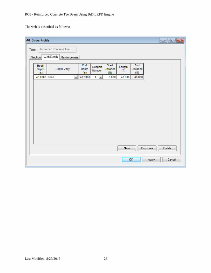
The web is described as follows:
RC8 - Reinforced Concrete Tee Beam Using BrD LRFD Engine
Last Modified: 8/29/2016 24
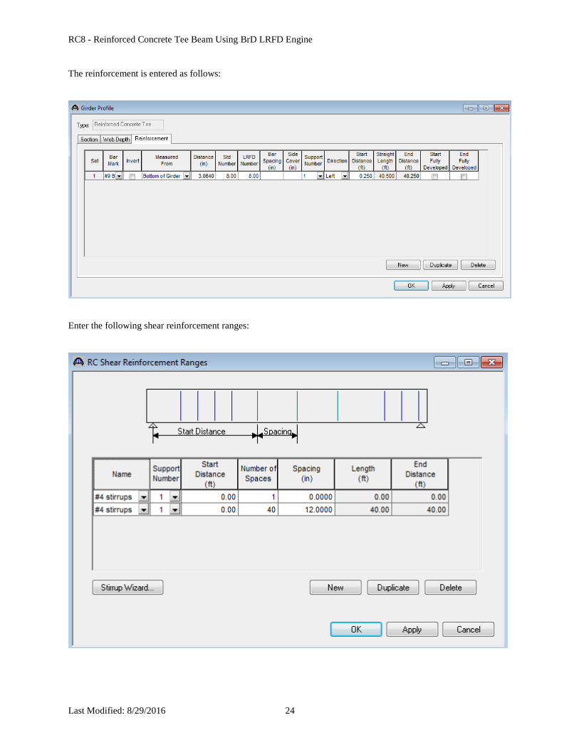
The reinforcement is entered as follows:
Enter the following shear reinforcement ranges:

RC8 - Reinforced Concrete Tee Beam Using BrD LRFD Engine
Last Modified: 8/29/2016 25
To perform a design review, select the View Analysis Settings button on the toolbar to open the window shown
below. Use the “HL-93 Design Review” template to select the vehicles to be used and click Ok.
Next click the Analyze button on the toolbar to perform the design review.

RC8 - Reinforced Concrete Tee Beam Using BrD LRFD Engine
Last Modified: 8/29/2016 26
You should always review the analysis log that is created when you do an analysis with the BrD LRFD engine.
Informational messages are displayed in blue, warning messages are displayed in green and error messages are
displayed in red font.
The following steps are performed when doing a design review using the BrD LRFD analysis engine:
1. Finite element models are generated for the dead load and live load analyses. A Stage 1 FE model is
generated for the dead loads on the reinforced concrete beam. A Stage 3 FE model is generated for the live
load analysis. Reinforced concrete beams only have 1 stage so the Stage 1 and Stage 3 models contain the
same cross section properties.
The model generated by the export to the BrD LRFD analysis engine will contain node points at locations
where the cross section properties change, span tenth points, support locations, and user defined points of
interest.

RC8 - Reinforced Concrete Tee Beam Using BrD LRFD Engine
Last Modified: 8/29/2016 27
2. The Stage 1 FE model is analyzed for the dead load. The Stage 3 FE model is loaded with unit loads at
each node to generate influence lines for the beam. The influence loads are then loaded with the selected
vehicles to find the maximum live load effects.
3. Load combinations are generated for the loadings and specification checks are performed at each of the
nodes in finite element model as well as the locations where schedule based reinforcement is developed.
The report containing the calculations of the rebar development locations is shown below.

RC8 - Reinforced Concrete Tee Beam Using BrD LRFD Engine
Last Modified: 8/29/2016 28
A summary and a detailed report of the computed live load distribution factors are available.

RC8 - Reinforced Concrete Tee Beam Using BrD LRFD Engine
Last Modified: 8/29/2016 29
A summary report of the specification check results is also available. This summary report lists the design ratios for
each spec article at each spec check location point. The design ratio is the ratio of capacity to demand. A design
ratio less than one indicates the demand is greater than the capacity and the spec article fails. A design ratio equal to
99.0 indicates the section is subject to zero demand.
RC8 - Reinforced Concrete Tee Beam Using BrD LRFD Engine
Last Modified: 8/29/2016 30
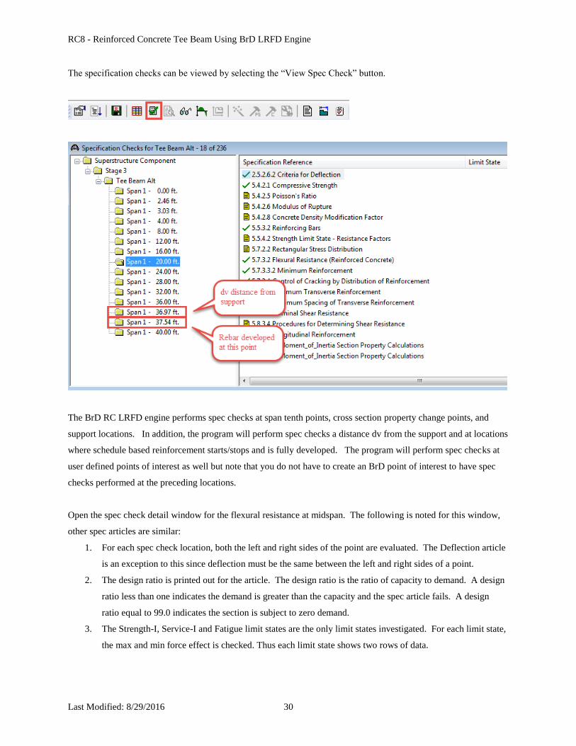
The specification checks can be viewed by selecting the “View Spec Check” button.
The BrD RC LRFD engine performs spec checks at span tenth points, cross section property change points, and
support locations. In addition, the program will perform spec checks a distance dv from the support and at locations
where schedule based reinforcement starts/stops and is fully developed. The program will perform spec checks at
user defined points of interest as well but note that you do not have to create an BrD point of interest to have spec
checks performed at the preceding locations.
Open the spec check detail window for the flexural resistance at midspan. The following is noted for this window,
other spec articles are similar:
1. For each spec check location, both the left and right sides of the point are evaluated. The Deflection article
is an exception to this since deflection must be the same between the left and right sides of a point.
2. The design ratio is printed out for the article. The design ratio is the ratio of capacity to demand. A design
ratio less than one indicates the demand is greater than the capacity and the spec article fails. A design
ratio equal to 99.0 indicates the section is subject to zero demand.
3. The Strength-I, Service-I and Fatigue limit states are the only limit states investigated. For each limit state,
the max and min force effect is checked. Thus each limit state shows two rows of data.

RC8 - Reinforced Concrete Tee Beam Using BrD LRFD Engine
Last Modified: 8/29/2016 31
4. The LL load combination is shown in this column. If the location is not at a node in the FE model (eg, the
node is at a point where the rebar is fully developed), this column will list two load combinations separated
by a comma. The first load combination is the combination considered at the left end and the second load
combination is the combination considered at the right end of the FE element that contains this location.
The resulting load displayed is a linear interpolation between the two displayed load cases.

RC8 - Reinforced Concrete Tee Beam Using BrD LRFD Engine
Last Modified: 8/29/2016 32
Tabular dead load and live load analysis results are available in the Analysis Results window.

RC8 - Reinforced Concrete Tee Beam Using BrD LRFD Engine
Last Modified: 8/29/2016 33
Note these values include dynamic load allowance, distribution factors and any live load scale factor entered on the
Analysis Settings window.
The Method of Solution manual can be accessed from the Help menu in BrD.
You may find different live load values between the BrD LRFD analysis engine
and the BRASS™ LRFD engine due to a difference in how the live load distribution
factors are applied. The BRASS™ engine applies the LL distribution factor based on
the region where the analysis point is located. The BrD engine applies the LL
distribution factor based on the region where the axle is positioned.

RC8 - Reinforced Concrete Tee Beam Using BrD LRFD Engine
Last Modified: 8/29/2016 34


