

Relationship Between Basic Operation of Boolean and Basic Logic Gate
• The basic construction of a logical circuit is gates• Gate is an electronic circuit that emits an output signal
as a result of a simple Boolean operation on its inputs• Logical function is presented through the combination
of gates• The basic gates used in digital logic is the same as the
basic Boolean algebra operations (e.g., AND, OR, NOT,…)

• The package Truth Tables and Boolean Algebra set out the basic principles of logic.
A B F0 0 00 1 01 0 01 1 1
A B F0 0 00 1 11 0 11 1 1
A B F0 0 00 1 11 0 11 1 1
A B F0 0 00 1 01 0 01 1 1
F
F
F
F
Name Graphic Symbol Boolean Algebra Truth Table
AB
AB
AB
AB
A F
AND
OR
NOT
NAND
NOR
F = A . B Or F = AB
F = A + B
_____ F = A + B
____ F = A . B Or F = AB
_ F = A
B F 0 1 1 0
the symbols, algebra signs and the truth table for the gates
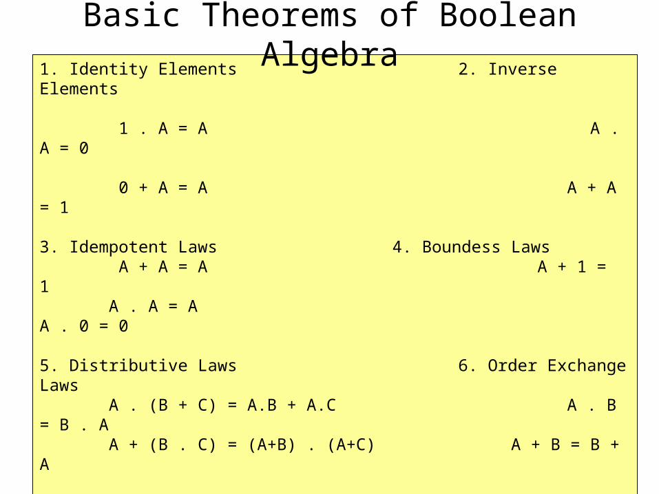
1. Identity Elements 2. Inverse Elements 1 . A = A A . A = 0 0 + A = A A + A = 1 3. Idempotent Laws 4. Boundess Laws A + A = A A + 1 = 1 A . A = A A . 0 = 0 5. Distributive Laws 6. Order Exchange Laws A . (B + C) = A.B + A.C A . B = B . A A + (B . C) = (A+B) . (A+C) A + B = B + A 7. Absorption Laws 8. Associative Laws A + (A . B) = A A + (B + C) = (A + B) + C A . (A + B) = A A . (B . C) = (A . B) . C 9. Elimination Laws 10. De Morgan Theorem A + (A . B) = A + B (A + B) = A . B A . (A + B) = A . B (A . B) = A + B
Basic Theorems of Boolean Algebra

Exercise 1
• Apply De Morgan theorem to the following equations:F = V + A + L
F = A + B + C + D
• Verify the following expressions:
S.T + V.W + R.S.T = S.T + V.W
A.B + A.C + B.A = A.B + A.C

Relationship Between Boolean Function and Logic Circuit
A
B Q
Boolean function Q = AB + B = (NOT A AND B) OR B
Logic circuitA
AB
B= AB + B

Relationship Between Boolean Function and Logic Circuit
• Any Boolean function can be implemented in electronic form as a network of gates called logic circuit
AB
F
A.B = AB
CD C + D
= AB + C + D

G = A . (B + C + D)
A
B
CD
G = A . (B + C + D)
C + D
B + C + D

Truth Table

A
B Q
AAB
B= AB + B
Produce a truth table from the logic circuit
A B A AB Q
0 0 1 0 0
0 1 1 1 1
1 0 0 0 0
1 1 0 0 1

G = A . (B + C + D)
Exercise 2
• Build a truth table for the following Boolean function

Karnaugh Map
• A graphical way of depicting the content of a truth table where the adjacent expressions differ by only one variable
• For the purposes simplification, the Karnaugh map is a convenient way of representing a Boolean function of a small number (up to four) of variables
• The map is an array of 2n squares, representing all possible combination of values of n binary variables
• Example: 2 variables, A and B
A B A B
A B A B
00 01
10 11
BA B
A
B
A
BA
1 0
1
0

0000 0001
0100
1100
1000
AB C D
A B
C D
A B
CD
A B
A B
C DC D
4 variables, A, B, C, D 24 = 16 squares

000 010 110 100
001 011 111 101
AB
C
A B
C
A BC A B A B
000 001
010 011
110 111
100 101
AB C
A B
C
A B
A B
A B
00 01 11 10
0
1
00
01
11
10
0 1
• List combinations in the order 00, 01, 11, 10
C

A B C F
0 0 0 1
0 0 1 0
0 1 0 0
0 1 1 1
1 0 0 1
1 0 1 1
1 1 0 0
1 1 1 0
Truth Table
Karnaugh Map
1 1
1 1
0 0 0 1 1 1 1 0BC
A
0
1
A
A
B CB C B C B C
How to create Karnaugh Map
1. Place 1 in the corresponding square
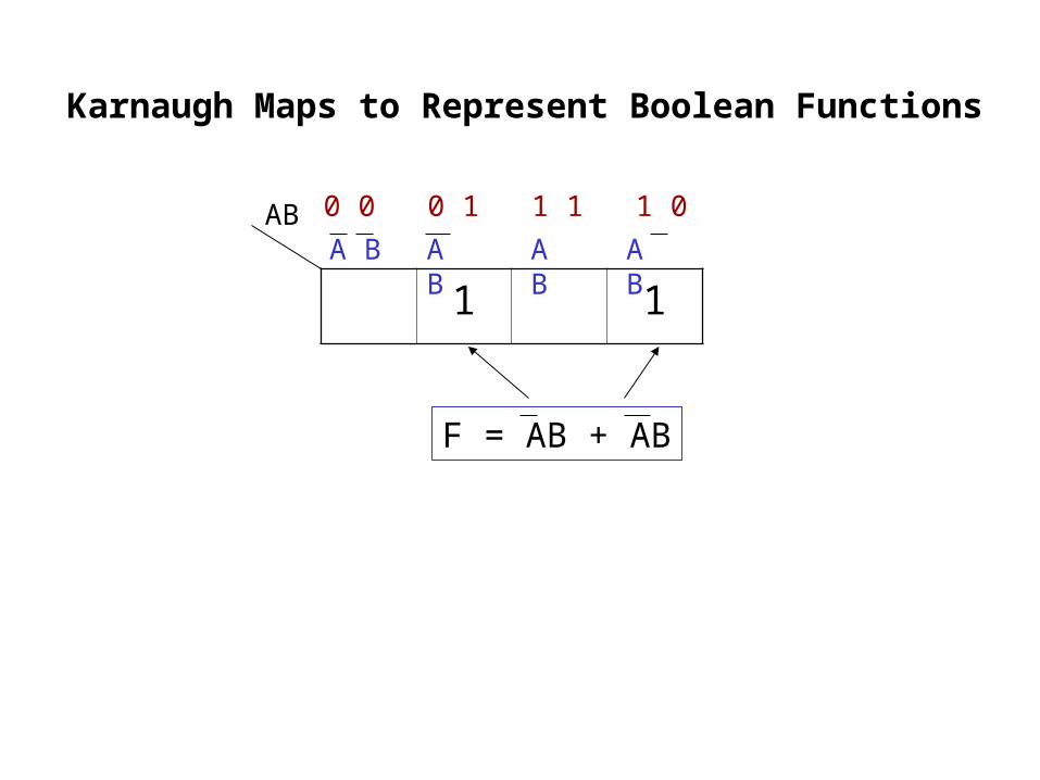
1 1
0 0 0 1 1 1 1 0AB
F = AB + AB
A BA B A B A B
Karnaugh Maps to Represent Boolean Functions
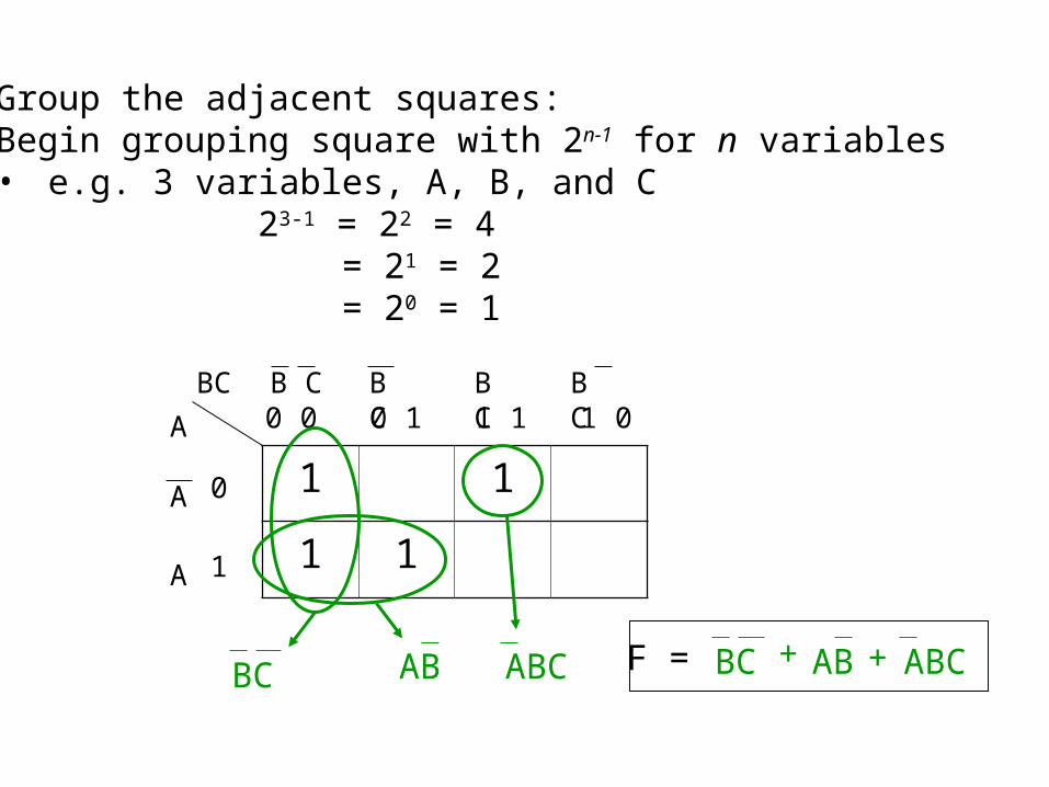
2. Group the adjacent squares:Begin grouping square with 2n-1 for n variables• e.g. 3 variables, A, B, and C
23-1 = 22 = 4 = 21 = 2 = 20 = 1
1 1
1 1
0 0 0 1 1 1 1 0BC
A
0
1
A
A
B CB C B C B C
ABBC ABC F = BC AB ABC+ +

1
1 1 1 1
0 0 0 1 1 1 1 0BC
A
0
1
A
A
B CB C B C B C3 variables: 23-1 = 22 = 4 22-1 = 21 = 2 21-1 = 20 = 1
A
BC
F = A + BC
1 1
1
1
1 1 1
AB 01
01
00
00
CD
11
10
1011
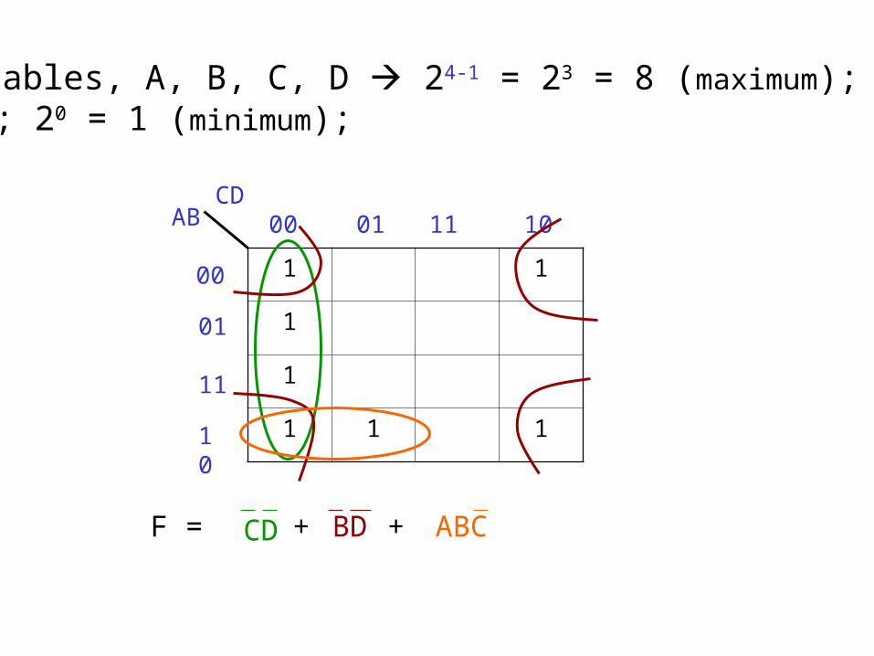
4 variables, A, B, C, D 24-1 = 23 = 8 (maximum); 22 = 4;21 = 2; 20 = 1 (minimum);
CD + BD ABC+F =

The following diagram illustrates some of the possible pairs of values for which simplification is possible:

Karnaugh Map
Boolean Function
Logic Circuit
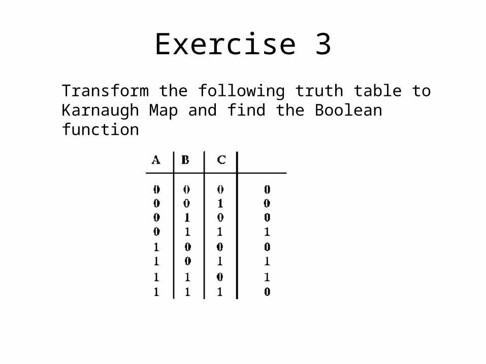
Transform the following truth table to Karnaugh Map and find the Boolean function
Exercise 3


