
Report No. CG-D-29-96
Comparative Analysis of the Reliability ofCarbon Dioxide Fire Suppression Systems
As Required by 46 CFR, SOLAS 11-2, and NFPA 12
Robert ZaloshDouglas Belier
Robert Till
Center for Firesafety StudiesWorcester Polytechnic Institute
Worcester, MA 01609
D.W. Alley
U.S. Coast Guard'Research & Development Center1082 Shennecossett Road
Groton, CT 06340-6096
Final ReportMay 1996
This document is available to the U.S. public through theNational Technical Information Service, Springfield, Virginia 22161
Prepared for:
U.S. Department of TransportationUnited States Coast GuardOffice of Research and DevelopmentWashington, DC 20593-0001
19961213 101 '=0

NOTICE
This document is disseminated under the sponsorship of theDepartment of Transportation in the interest of informationexchange. The United States Government assumes no liabilityfor its contents or use thereof.
The United States Government does not endorse products ormanufacturers. Trade or manufacturers' names appear hereinsolely because they are considered essential to the object ofthis report.
The contents of this report reflect the views of the Coast GuardResearch & Development Center. This report does not consti-tute a standard, specflcat re on.
SGI.T. ntrherj Commanding Officer
United States Coast GuardResearch & Development Center1082 Shennecossett Road
, cGroton, CT 06340-6096
ii

Technical Report Documentation Page1. Report No. 2. Government Accession No. 3. Recipient's Catalog No.
CG-D-29-96
4. Title and Subtitle 5. Report Date
Comparative Analysis of the Reliability of Carbon Dioxide Fire Suppression May 1996
as Required by 46 CFR, SOLAS 11-2, and NFPA 12 6. Performing Organization Code3308.1.96
7. Author(s) 8. Performing Organization Report No.
Robert Zalosh, Douglas Belier, Robert Till, and D.W. Alley R&DC 04/96
9. Performing Organization Name and Address 10. Work Unit No. (TRAIS)
Center for Firesafety Studies Safety and Human Resource Division SHRD Report No. 105Worcester Polytechnic Institute U.S. Coast Guard 11. Contract or Grant No.Worcester, MA 01609 Research and Development Center DTCG39-94-F-E00407
Groton, CT 06340-6096
12. Sponsoring Agency Name and Address 13. Type of Report and Period Covered
U.S. Coast Guard Department of Transportation Final ReportChief, Marine Safety Directorate U.S. Coast GuardWashington, DC 20593 Office of Research and Development
Washington, DC 20593-0001 14. Sponsoring Agency Code
Commandant (G-MMS-4)
15. Supplementary Notes
U.S. Coast Guard Research and Development Center point of contact: LCDR Dave Alley (860) 441-2861.
16. Abstract
Coast Guard regulations governing the design and installation of total flooding carbon dioxide fire suppression systems forshipboard machinery spaces are compared to the equivalent standards promulgated by the International Maritime Organization(IMO) and the National Fire Protection Association (NFPA). Differences among the standards that can affect the reliability of acarbon dioxide system involve: 1) the quantity of carbon dioxide required for a machinery space installation; 2) manual versusautomatic system actuation; 3) requirements for closure of ventilation systems, doors, vents, duct dampers, etc., and 4) requiredcarbon dioxide discharge rates and piping design guidelines to achieve the required discharge rates.
A Failure Modes and Effects Analysis (FMEA) has been conducted for a prototypical modern high pressure carbon dioxidesystem for a large cruise ship. The FMEA has identified seven system components with failure modes that could affect theability of the system to extinguish a machinery space fire. Potential sources of failure rate data for these and other componentsare identified.
Fire incident reports involving machinery spaces equipped with total flooding carbon dioxide systems have been complied andreviewed. The carbon dioxide system extinguished the fire in 35% of those fires and either temporarily extinguished orcontrolled the fire in another 23% of the incidents. The primary reason for the limited effectiveness of the carbon dioxidesystems seems to be carbon dioxide leakage due to either: 1) unclosed doors, vents, ducts, etc.; 2) fire/explosion damagedclosures (particularly in fires with delayed system actuation); and 3) crew or firefighter early re-entry into the machinery spacebefore temperatures have been reduced sufficiently to preclude re-ignition. System failure rate data for land-based carbondioxide systems indicate that high pressure systems have had failure rates in the range of 4% to 53%, whereas low pressuresystems have had failure rates (0.2% to 0.4%) at least an order-of-magnitude lower.
Possible ways to provide improved system reliability and to streamline the Coast Guard standard and make it more compatiblewith the other two standards are presented in the conclusions to this report.
17. Key Words 18. Distribution Statement
Carbon dioxide, C0 2, machinery space, This document is available to the U.S. public throughInternational Maritime Organization (IMO), reliability, the National Technical Information Service,Coast Guard regulations, CO2 high pressure, CO 2 low Springfield, VA 22161.,pressure I
19. Security Classif. (of this report) 20. SECURITY CLASSIF. (of this page) 21. No. of Pages 22. Price
UNCLASSIFIED UNCLASSIFIED
Form DOT F 1700.7 (8/72) Reproduction of form and completed page is authorized
iii QjATm IUSPEOITED 3

(I)
CU 04 U0) - 64 >
ca cgow)) o EN
1~0-
o= m oS222 cW. 12 ' CD :2 CCJ coC
S 3, E~~C cr JU ODJr 0 L 0. D r ) M u0 Vo
E C D
0 a)
'a) 0~ M0N--n Mq 4 C t D 0cc 0-) 0 o 1 0N CI N 0 0 - x V CY
C))
IIo 00L.
LL0 < 0
> CD00 E ~ > ~ 6 LL 9L L LLOL6 9 cc
c L I
Y CD 8) 7 4321 inhe
V)) o
E0 (
co~ 2o E Ia) G) E S
0 --
LL 0
rAO
LU .2 ~ o Eo
0. 0) -50 CC)
L) -0 E. EE ~ Q C-E c Nc
o 0i
Cl)V V) ( C* WD0DD . -
0 C) CDC DC)EE nU) wDEc mr =: a )w0o -.
o 0 YI-( :
o c o =: )lLC0 >0 0 CV toN00 , D
CUCID
0~~C 75 L 0 0
I.a.
0. 0
S2>. *s , E a CU.k
(DM ,V)0 2

TABLE OF CONTENTS
Page
L ist of F igures ............................................................................................................................ vi
L ist of T ables ............................................................................................................................. vi
1. INTRODUCTION ............................................................................................................. 1
2. COMPARISON OF CO2 SYSTEM STANDARDS ........................................................... 22.1 Required CO2 Quantities/Concentrations ..................................................................... 22.2 Actuation Controls and Delay Times ......................................................................... 42.3 Piping and Nozzles ................................................................................................... 52.4 Enclosure Openings and Ventilation ........................................................................... 62.5 Miscellaneous Items ................................................................................................... 7
3. CO 2 SYSTEM HISTORICAL PERFORMANCE ............................................................. 93.1 Statistical Summary from Reference 6 ................................ 93.2 Common System Problems in Fire Incidents ............................................................. 103.3 CO 2 System Asphyxiation Hazard ............................................................................ 11
4. SYSTEM RELIABILITY ANALYSES ......................................................................... 124.1 Failure Modes and Effects Analysis ......................................................................... 124.2 CO2 System and Component Reliability Data Sources ............................................... 14
4.2.1 Machinery Space Fire Incident Database ......................................................... 144.2.2 Stronach (Alcan Aluminum) ........................................................................... 144.2.3 Miller (Navy and FM) ..................................................................................... 164.2.4 Center for Chemical Process Safety ............................................................... 164.2.5 Reliability Analysis Center .............................................................................. 164.2.6 Other Sources .............................................................................................. 16
5. CONCLUSIONS and RECOMMENDATIONS ............................................................. 18
6. R E FE R E N C E S .................................................................................................................... 2 1
APPENDIX A: Regulation Comparison Table .................................................................. A-1
APPENDIX B: CO2 System Failure Modes and Effects Analysis ........................................ B-1
APPENDIX C: CO2 System Pipe Length Limitations ......................................................... C-1
APPENDIX D: Summaries of Representative CO2 System Problems in Selected Incidents ...... D-1
V

List of Figures
Page
1. Comparison of CO 2 Quantities Required .......................................................................... 3
List of Tables
Page
1. CO 2 System Effectiveness ................................................................................................ 92. CO2 System Limited Effectiveness .................................................................................. 103. Critical Components ........................................................................................ ................ 134. Reference 7 Failure Summ ary ......................................................................................... 15
vi

1. INTRODUCTION
Carbon dioxide total flooding fire suppression systems are utilized in engine rooms, generatorrooms, paint lockers, cargo holds, and other enclosed areas on commercial ships. Several
different regulations and standards govern the design and installation of carbon dioxide
suppression systems. The relevant regulations for vessels falling under U.S. Coast Guard
jurisdiction are 46 CFR 34.15 (Ref 1), 46 CFR 76.15, and 46 CFR 95.15, which are prescriptive
standards with detailed design specifications. The relevant standard promulgated by the
International Maritime Organization (IMO), as described in the most recent SOLAS volume
(Ref 2), is a simple performance based standard with minimal design guidance. Both of these
standards differ from the National Fire Protection Association (NFPA) carbon dioxide system
standard (Ref 3) and the equivalent Factory Mutual (FM) standard (Ref 4).
This report is intended to compare the pertinent carbon dioxide (CO 2) system standards and
discuss how the differences may affect system performance and reliability for machinery spaceinstallations. Comparisons are discussed in Section 2, with detailed tables and sample pipe flow
calculations provided in Appendix A and C respectively. Since most shipboard CO2 systems arehigh pressure systems with banks of CO 2 cylinders, the emphasis is on high pressure systems.
One approach to analyzing system reliability and performance is to compile incident reports andstatistics on the historical performance of CO 2 systems. Section 3 provides a summary of CO2
system performance described in Coast Guard incident reports involving engine room fires.
Common system failure modes and responsible system components are identified in those reports.
Report narrative summaries are provided in Appendix D.
Another approach to assessing system reliability is to conduct a Failure Modes and Effects
Analysis in which the consequences of individual component failures are identified. The highpressure CO2 system FMEA is presented in Appendix B. Key results, including the identification
of critical system components that are required for discharge actuation and the delivery of CO2 to
the fire compartment, are summarized in Section 4.1. Potential sources of data on the component
failure rates and failure probabilities are listed in Section 4.2.

2. COMPARISON OF CO2 SYSTEM STANDARDS
Item by item comparisons of the carbon dioxide total flooding system requirements in the Code of
Federal Regulations (Ref. 1), the IMO/SOLAS regulations (Ref. 2), and NFPA 12/FM 4-1 IN
(Refs. 3 and 4) are presented in table form in Appendix A. These comparisons are summarized
here under the categories Required Quantities/Concentrations (Sec 2.1), Discharge Actuation
Controls and Delay Times (Sec 2.2), Piping and Nozzles (Sec 2.3), Enclosure Openings and
Ventilation (Sec 2.4), and Miscellaneous Items (Sec 2.5). Differences that could affect system
reliability are discussed. System reliability refers here to the ability of the system to extinguish a
machinery space fire.
2.1 Required CO2 Quantities/Concentrations
The amount of carbon dioxide required according to the CFR (Ref 1) is specified in terms of a
flooding factor that is defined as the volume of space protected per pound of CO2. The amount
of CO2 required in the IMO/SOLAS regulations is specified in terms of a volumetric
concentration. The relationship between the these two specifications depends on the assumed
specific volume of CO 2, which is taken as 0.56 m3/kg in Reference 2. The IMO specified
volumetric concentration for machinery spaces (40% of the net volume exclusive of machinery
casing volume) is independent of volume, whereas the CFR flooding factors increase with
increasing machinery space net volume.
Figure 1 is a comparison plot of the required mass of CO2 versus machinery space net volume, for
machinery spaces in which the machinery casing volume is no more than 12% of the space gross
volume. When machinery volumes are 2,000 m3 and larger, the required amounts are virtually
identical. At smaller machinery space volumes, the CFR requires more CO2 than IMO/SOLAS.
For example, in a 100 m3 machinery space, the CFR requires about 22% more CO2 than does
IMO.
2

Cfo
00
cc0
-- U 0
0
1 u*
1.~~~CD
(61) zo Saa

Thus, there is no significant difference in required quantities for moderate size and large
machinery spaces, but significantly more CO2 is required by the CFR for small machinery spaces.
The primary difference between the marine (CFR, IMO) and land based (NFPA) required CO2
quantities is that the land based requirements are fuel specific and dependent on whether the
design basis fire is a surface fire or a deep-seated fire. Deep-seated fires and certain flammable
liquids and vapors require substantially higher CO2 concentrations for extinguishment. Most
machinery space fires involve either fuel oil or lubricating oil, and the concentration requirements
for these fires are identical in the land-based and marine standards. Some machinery space fires
involve electrical equipment and cables, which have the potential of becoming deep-seated and
thus NFPA requires higher CO 2 concentrations for these fires than called for in the CFR and IMO
regulations.
2.2 Actuation Controls and Delay Times
Actuation control requirements are virtually the same in the CFR and IMO regulations. In both
cases, two separate control valve actuators are required; one actuator to release the CO 2 and
another actuator to open a valve admitting the CO2 into the desired machinery space. Both
regulations also allow two actuation station locations, with at least one location being in the
vicinity of the machinery space but safely outside it. Neither shipboard regulation allows
automatic release of CO 2 upon detection, whereas the NFPA standard states automatic actuation
is required unless the authority having jurisdiction rules that it "could result in an increased risk."
Furthermore, NFPA 12 specifies only one control actuation to discharge CO2 into the enclosure.
The discharge time for both CFR and IMO CO 2 total flooding applications are identical: 85% of
required amount within 2 minutes. The delay times do, however, differ. The CFR requires a
minimum of 20 seconds while IMO systems must provide a "suitable period before the medium is
released" (Ref. 2). In this aspect IMO and NFPA are similar. NFPA indicates that the delay time
shall be "of sufficient duration to allow for evacuation under "worst case" conditions ...........
(Ref. 3). However, the NFPA requires that drills be performed to determine the minimum time
4

required for personnel to remove themselves from the protected area, after identifying the warning
signal, while IMO does not.
This is a difficult issue: the sooner the system is activated, the more likely the fire will be
controlled. However, because of the asphyxiation hazard discussed in Section 3.3, sufficient time
must be provided for evacuation of personnel, the 20 second minimum delay time in the CFR is
most likely sufficient, given that manual activation of the CO2 system is required. On the other
hand, the approach implied in the NFPA standard is that automatic actuation be utilized with a
conservatively long duration delay to allow evacuation. Presumably, the different approaches to
system actuation stem from different perceptions on whether a fire that is large enough to actuate
an automatic detector can/should be readily extinguished without system discharge.
2.3 Piping and Nozzles
There are important differences in the pipe size specifications in the three standards. The IMO
standard does not provide any pipe size specifications. The CFR standard and the CG guidelines
for plan review and inspection (Ref. 5) specify minimum pipe diameters and minimum and
maximum nozzle orifice. The NFPA standard provides a method for calculating the pressure drop
in pipe segments with known lengths and diameters and design CO2 flow rates. These
calculations are intended to verify that the nozzle pressures will not fall below the NFPA 12
minimum requirements for high pressure systems (300 psig) and low pressure systems (150 psig).
Neither the CFR nor the IMO standards restrict the lengths of CO2 distribution piping. This is a
concern in that there could be excessive pressure drops in long runs of piping. In order to
investigate the pressure drop effects in lengthy pipe runs, calculated pressure drops are shown in
Appendix C for different quantities of CO2 at the minimum and maximum allowable orifice areas
per the CFR standard. The methodology of NFPA 12 is used for these pressure drop calculations.
The results presented in Table C-3 of Appendix C show that under most conditions, when the
distribution piping is of typical lengths, the pressure drop through the nozzles meets or exceeds
the NFPA 300 psi requirement.
5
Nozzle location is another important factor affecting C02 dispersal. Both the CFR and IMO
standards call for uniform spacing of nozzles but give no guidance on allowable distances between
nozzles. The CG inspection guidelines (Ref 5) suggest that nozzles can be located at mid
elevation in the machinery space because most machinery space fires occur at low elevations.
However, there are at least two fires described in Appendix D that involve electrical cable burning
at upper elevations. These upper elevation fires cannot be expected to be extinguished with
nozzles situated at mid elevation as suggested by Reference 5.
The CFR specifies that ferrous pipes must have corrosion protection, inside and out, while IMO
has no such provision. Given that the systems in question are marine-based, and therefore
potentially exposable to a corrosive environment, corrosion protection should be a design
specification. The effect of not explicitly requiring (or having) corrosion protection on the
reliability of the system is expected to be relatively small.
The CFR specifies the allowable branch line diameters, while IMO does not. Once again the IMO
regulations appear to treat this point as a design option; not necessarily within the realm of
regulation. Additionally, the CFR specifies the pipe schedule for given sizes of pipe, while IMO
appears to treat this as another design specification.
2.4 Enclosure Openings and Ventilation
Machinery space bulkhead openings and ventilation systems must be closed prior to CO2
discharge in order to allow CO2 concentrations to reach the levels required for extinguishment.
These closings are also necessary to maintain an inert atmosphere long enough to achieve
sufficient cooling of fire heated equipment, bulkheads, etc. to prevent re-ignition upon air reentry
into the machinery space. Neither the CFR nor the IMO standard specifies a required
concentration hold time, but the NFPA standard does specify hold times for surface fires and
deep-seated fires. Presumably, a CO 2 discharge test is required to demonstrate these hold times.
6

The CFR and IMO standards have somewhat different requirements for sealing off enclosure
openings and ventilation. The CFR requires the mechanical ventilation to be shut down
automatically upon CO 2 system actuation, while the IMO standard stipulates that "means shall be
provided to close all openings which may admit air or allow gas to escape from a protected
space." The CG/CFR regulations (46 CFR 76.15-35) also specify that "means shall be provided
for closing all openings to the space protected from outside such space." Installed closures are
required in the lower portion of the machinery space, but canvas or similar porous material is
allowed for openings in the upper region.
It would seem that the CFR regulations are more stringent than the IMG regulation in this aspect
because of the requirement for automatic shutdown of mechanical ventilation and the provision of
closures from outside the machinery space. However, the allowance of flimsy, porous materials
for openings situated in the upper portion of the space may be less stringent than a strict
interpretation of the IMO regulations. In any event, both the CFR and IMO standards fall far
short of the NFPA standard in demonstrating a specified hold time.
2.5 Miscellaneous Items
The CFR requires that the mechanical ventilation system be automatically shut down upon
activation of the C0 2 system. IMN stipulates that "Means shall be provided to close all openings
which may admit air to or allow gas to escape from a protected space." (Ref. 2, Reg. 5, 1.4).
Presumably the means to close all openings includes turning off any mechanical ventilation;
however, this is not explicitly stated. Since not shutting down the ventilation system would result
in a lower volumetric concentration of CO2, this item could prove to be significant. The CFR
requirement is regarded as being more reliable because it specifically states that the mechanical
ventilation system be automatically shut down. While the IMO regulation does not preclude
automatic mechanical ventilation system shutdown, not specifying it could result in a less reliable
system.
7

The CFR requires an installation inspection. The CFR provides details of tests to check the
leakage from the system after pressurizing the piping, and of blowing down the piping for small
systems. SOLAS has no requirement for installation inspections. Presumably an installation
inspection and system test is part of the installation procedure for IMO compliant CO 2 systems.
However, if it is not, the reliability of IMO compliant CO 2 systems could be significantly
jeopardized.
Minor differences which should not affect the reliability of the systems involve the nozzle
discharge area, and pressure relief for the compartment, distribution manifold, and storage
cylinders. For these items the CFR has a requirement but IMO does not. These items are not
expected to affect the reliability of the CO 2 system. The IMO appears to treat the nozzle
discharge area as a design specification.
The need for compartment pressure relief arises after the CO2 has been released. Not having it
could result in the CO 2 release causing an overpressure condition and thus forming an opening in
the compartment large enough to leak excessive CO2. Not having a pressure relief valve on the
distribution manifold could result in damage to manifold during agent discharge and thus prevent
the CO 2 from reaching the fire space. Not having cylinder pressure relief could result in agent
leakage before a fire, i.e., the CO 2 would be unavailable to fight a fire. Two points are noted for
pressure relief provisions: 1) these overpressurization events are relatively rare when compared
to other possible failure events, and 2) IMO seems to treat pressure relief as a specification of
every design and therefore something that need not be mandated.
8

3. CO2 SYSTEM HISTORICAL PERFORMANCE
3.1 Statistical Summary from Reference 6
Reference 6 provides a discussion of the fire suppression requirements for shipboard machinery
spaces. From this reference, the most common machinery space fire involves a fuel oil spray
ignited by a hot surface.
A total of 26 fires involved the discharge of a CO2 system (132 total machinery space fire
incidents were considered). Table 1 (Table 2.3.2-5 of Reference 6) provides a breakdown of the
machinery space fire incidents involving fixed, total flooding carbon dioxide systems
(CO 2 System) and the reported effectiveness of such systems.
Table 1. CO2 System Effectiveness
CO 2 System Effectiveness Type & Number of Fires Percent (%)
Extinguished Fire Spray (9) 34.6Temporarily Extinguished Fire Spray (3), 15.4
Electrical (1)Controlled Fire Spray (1), 7.7
Electrical (1)Ineffective Spray (5), Pool (2), 42.3
Electrical (1), Other (1),Unknown (2)
A temporarily extinguished fire is a one that was suppressed for a period of at least 20 minutes
and then re-ignited. A controlled fire is one that is confined to its ignition area (i.e., small flames).
The CO 2 System was ineffective against those fires which continued to burn despite the presence
of the CO 2 fire suppression agent.
9
3.2 Common System Problems in Fire Incidents
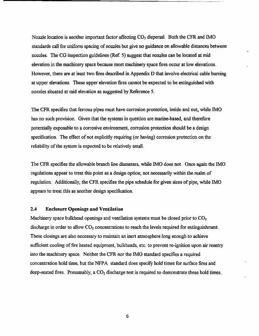
Table 2 (based on Table 2.3.2-6 of Reference 6) provides information concerning why CO 2
systems were less than fully effective. Of the reasons listed, the category "activated too late" may
seem counter intuitive. It would seem reasonable that the longer a fire bums, the less oxygen
would be present and the easier the fire would be to extinguish. The available data does not
support this position. There is a correlation between long delays in activating the CO2 system and
its failure to extinguish the fire. A causal relationship between activation delays and failure to
extinguish has not been established. It is possible that long delay times permit heat distortion of
vents, doors, etc., which precludes the formation of a gas tight enclosure (see Appendix D. 1). If
this is the case, the category "activated too late" is actually a specific case of the category
"excessive agent leakage from space."
Table 2. CO2 System Limited Effectiveness
Reason for Limited Effectiveness of CO2 System No. of %Incidents
Excessive Agent Leakage from Machinery Space 8 47.1Activated Too Late 3 17.6Failure to Discharge When Activated 1 5.9Other 1 5.9Unknown 4 23.5
The excessive agent leakage was typically the result of not closing the vents or doors of the space
prior to discharging the CO2. In two cases, the mechanical ventilation was not shut down (one of
these cases also involved not closing the vents or doors). In at least one case, the door to the
space was opened too soon after the CO 2 was released and thus the CO 2 leaked out before it
could extinguish or inert sufficiently to prevent re-ignition. The actual reason for not being able
to close the vents and/or doors was not provided in the accident reports.
10

One other reason for ineffective suppression, cited in two incidents, is the presence of fire in the
upper region of the machinery space. The CO2 concentrations in these regions may be below the
required values for extinguishment, especially for electrical cable fires.
3.3 CO2 System Asphyxiation Hazard
Personnel exposure to carbon dioxide concentrations of 7 to 10 volume percent or higher results
in loss of consciousness, with death occurring after 5 minutes at a concentration greater than
10 % (SFPE Handbook, 1st edition, p 1-238, 241). Since carbon dioxide system design
concentrations far exceed these concentrations, a primary reliability consideration is the
prevention of system discharge while personnel remain in the machinery space.
None of the fire incidents reviewed in Reference 6 and Appendix D of this report resulted in any
fatalities due to discharge into an occupied machinery space. However, there have been several
inadvertent discharge incidents resulting in fatalities in recent years. Although the authors are not
privy to written accounts and explanations of the causes of these incidents on commercial and
Coast Guard ships, they are more familiar with incidents on Navy ships and land based facilities.
One incident involved three fatalities when a system accidentally discharged while three sailors
were supposed to be doing preventive maintenance on a CO2 system in a paint locker. Another
incident resulted in a fatality when lethal concentrations of CO 2 propagated into an area outside
the enclosure in which a CO 2 system was being discharged during an installation test.
It is ironic that the leading failure mode for CO2 systems in fire incidents, namely excessive
leakage through unclosed openings, is also an important mode of inadvertent exposure of
personnel to potentially lethal CO 2 concentrations during CO2 test discharges. Another failure
mode that could lead to accidental discharge of a system into an occupied enclosure is the
mislabeling (or incorrect tripping) of the actuators for the directional valves that admit CO2 to the
various compartments. This failure mode can occur either during testing or during an intended
discharge, as listed in the Failure Modes and Effects Analysis (Appendix B).
11

4. SYSTEM RELIABILITY ANALYSES
One of the most widely used systems reliability methods is the Failure Modes and Effects Analysis
(FMEA). A FMEA is typically used to identify system component failures that could lead to
system failure and/or unacceptable hazards. It has been used in this study to identify critical CO 2
system components whose failure could lead to the inability of the system to extinguish a
machinery space fire or to inadvertently discharge CO 2 into an occupied area. Results are
summarized in Section 4.1.
After a FMEA or some other type of qualitative systems reliability study indicates that there are
indeed single component failures that could lead to unacceptable consequences, there is
motivation to go to some type of quantitative study such as a Fault Tree Analysis. Quantitative
Fault Tree Analyses require input data on individual component failure rates and system demand
rates, i.e. frequency of operation. The scope of this particular study does not include quantitative
analysis, but it does include a brief overview of relevant system/component failure rate databases
that could eventually be utilized in such an analysis. Results are presented in Section 4.2.
4.1 Failure Modes and Effects Analysis
Appendix B is a FMEA for a prototypical high pressure CO 2 system installed on a modem large
European passenger vessel. This particular system/vessel was selected because it was subjected
to a Coast Guard initial inspection at a local port (Boston) during the course of this investigation
and the system detailed drawings were made available to the authors.
Based on the FMEA tabulation in Appendix B for system discharge in response to manual
actuation, the following critical components have been identified in that their failure (failure mode
specified in Appendix) could lead to either no CO 2 being delivered to the machinery space on fire,
or to a reduced CO2 concentration that would prevent successful extinguishment. Drawings of
the system layout and locations of these components are provided in Appendix B.
12

Seven critical components are listed in Table 3. Three of those components have failure modes
that could prevent any CO2 from being delivered into the intended machinery space. Two of the
three components (directional valves and control panel wiring/switches actuating these valves )
could also deliver CO2 into an unintended, occupied area. In view of the possibility of creating a
potential asphyxiation hazard as well as preventing fire extinguishment, these two components
warrant special consideration about their reliability. Four other components have failure modes
that could result in significantly reduced CO2 concentrations in the machinery space. Many of the
total of 23 components listed in the FMEA for full discharge of the system were considered of
secondary importance, because there was a manual way of working around the failure, if a
crewmember was properly trained and familiar with the system. However, the manual work
around would significantly delay the discharge of CO2 to the point that serious injuries and
damage may be incurred before the fire is extinguished, if indeed it can be extinguished.
Table 3. Critical Components
Component Failure Mode EffectDistribution Piping Fully obstructed No C0 2 Delivered
Directional Valves for Fails closed No C0 2 Delivered and/orDistribution Piping C0 2 Discharge into occupied
area.
Nozzle Obstructed or Improperly Reduced CO2 ConcentrationLocated
C0 2 Cylinders Leaky or not properly refilled Reduced CO2 Concentration
Cylinder Valve Fails Closed or Obstructed Reduced C0 2 ConcentrationVentilation Shutdown Circuit Improperly installed or fails Reduced CO2 Concentration
and Duct Dampers open
Control Panel Wiring/Component Failure No C0 2 Delivered and/or(Switch for Directional Valve C0 2 Discharge into occupied
Actuation) area.
13

4.2 CO2 System and Component Reliability Data Sources
Several sources of system and component reliability data have been identified. These are
discussed in the following sections.
4.2.1 Machinery Space Fire Incident Database
The Machinery Space Fire Incident Database (MSFIdb) developed for Reference 6 is discussed in
Sections 3.1 and 3.2. This database is limited in that system level failures are typically considered.
If the system failed to activate, no indication of the component that actually failed is given in the
database. However, incident reports, which are available for many of the incidents in the
database, sometimes contain the details needed to identify the failed component.
4.2.2 Stronach (Alcan Aluminum)
Reference 7 presents CO2 system failure data gathered from aluminum rolling mills. The CO2
suppression systems installed in these mills are both high and low pressure, with automatic
activation via heat detectors. Stronach distinguished between system failure and system
malfunction. System failure was defined as lack of extinguishment with "single or multiple
discharges of CO2 and with portable fire extinguishers [such that repairs to the mill] must not
exceed twenty-four hours." System malfunction involved a problem with the system that did not
prevent satisfactory extinguishment as defined above.
Two studies were conducted. The first considered data for two low pressure systems between
1972 and 1986. This study found two failures and two malfunctions out of 1,238 activations.
The second study considered data for both low and high pressure systems, obtained between 1981
and 1986. In this study, two failures out of 504 low pressure system activations were logged. Six
failures out of 145 activations of high pressure CO 2 systems were logged. The results of this
reference are summarized in Table 4.
14
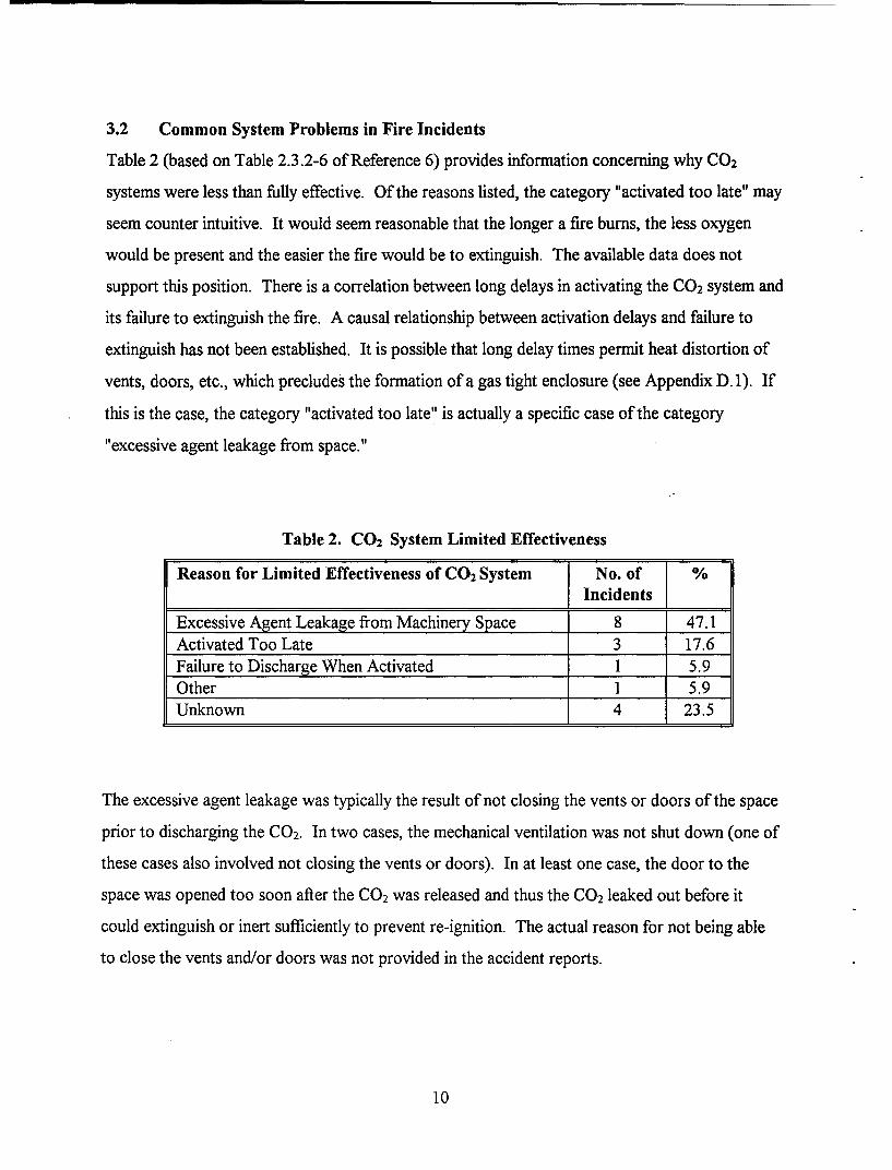
Table 4. Reference 7 Failure Data Summary
System Type Year System Failure System_____(%) Malfunction (%)
Low Pressure 1972-1986 0.16 0.16Low Pressure 1981 - 1986 0.4 0.8High Pressure 1981 - 1986 4.1 14.5
These failure rates are dramatically lower than those for shipboard machinery space incidents.
Furthermore, the failure rate for low pressure systems is an order-of-magnitude lower than for
high pressure systems. As a result of their improved reliability, Stronach recommended that all
new CO 2 systems be low pressure, and that ways of improving the reliability of high pressure
systems be investigated.
4.2.3 Miller (Navy and FM)
Reference 8 presents data that from the U.S. Navy and from Factory Mutual (FM) loss reports.
Few details are provided regarding the type of CO2 system, the areas protected, the number of
demands and failures, and the definition of effective as it pertains to the study.
According to Miller, Navy data for the years 1966 - 1970 indicate that CO2 systems were 96.1%
effective. The corresponding failure rate of 3.9% is remarkably close to the 4.1% failure rate
reported by Stronach for high pressure systems.
Data from FM loss reports indicated a CO2 system failure rate of 53%, or an order-of-magnitude
higher than those cited above. Miller points out that many successful system actuations go
unreported to FM, so there really is no basis for a direct comparison of Navy and industrial
incident failure rates.
15
4.2.4 Center for Chemical Process Safety
Reference 9 is a wealth of reliability data for selected process systems and equipment used in the
chemical process and other industries. Reliability data for flame detectors, pipes, hoses, valves,
and various fire protection/suppression systems are included. However, there was nothing for
C0 2 suppression systems. Sufficient data for individual CO2 system components seems to be
available to provide the basis for a quantitative risk analysis. Data is presented in either failures
per 106 hours or in failures per 10' demands. Various failure modes are considered for each
component, with data presented for several specific failure modes in most cases.
4.2.5 Reliability Analysis Center
Reference 10 is similar to Reference 9 in that many components are considered. While whole
systems are not presented (upon a cursory investigation), sufficient component data seems to be
available to analyze a simple CO2 suppression system. The task becomes one of sifting through all
of the data to extract the appropriate components and their associated failure data. This data is
also presented in terms of failures per hour and failures per demand, depending on the nature of
the component. This reference also provides the population of components that form the basis for
the failure data presented.
If both References 9 and 10 are used together, most (if not all) of the components of a prototype
shipboard CO2 suppression system could be modeled for a quantitative risk analysis.
4.2.6 Other Sources
One source of land based CO 2 system data that has not been investigated because of time/funding
limitations is the Fire Equipment Manufacturers Association. One source originally thought to
contain pertinent data, that in fact does not, is the National Fire Reporting System (NFIRS). This
reporting system deals with land based fires that involved fire department response; any mention
of a CO2 system activation would be incidental. Additionally, the Naval Safety Center fire
incident database was consulted for Reference 6. Of the 310 incidents reported, only 4 involved
the release of a CO2 fire suppression system and there were no failures (i.e., all fires involving a
16

CO2 system were extinguished). Because of this, the Naval Safety Center may not be a good
source of additional data.
17

5. CONCLUSIONS and RECOMMENDATIONS
0 There are three differences between the CG/CFR regulations and IMO/SOLAS
regulations for CO 2 total flooding systems that could affect the reliability of a system to
extinguish a machinery space fire. These differences are: 1) significantly less CO 2 required
by IMO/SOLAS in small machinery spaces; i.e., smaller than about 200 m3; 2) the
IMO/SOLAS regulations do not provide any specifications, guidance, or verification test
for piping designs to achieve the required CO2 flow rates; and 3) the CG/CFR regulations
require automatic shutdown of ventilation systems upon C0 2 system actuations, whereas
the IMO/SOLAS regulations merely stipulate that some means be provided to close
openings that allow air flow into or out of the machinery space.
* There are some significant differences between the CG/CFR regulations and the NFPA
regulations that could render shipboard CO 2 systems more prone to failure (inability to
extinguish) than land based systems. These differences include 1) the NFPA 12 allowance
of automatic discharge following detection, alarm, and a suitable delay time for personnel
evacuation; 2) NFPA 12 description of a calculation method to determine if piping
between the CO2 cylinder and the discharge nozzles is sufficiently short to allow nozzle
pressures to be at or above the minimum required pressures for effective dispersal of C0 2;
3) NFPA 12 stipulation that the required CO 2 concentration for surface fires be achieved
within 1 minute from start of discharge whereas the CFR and IMO regulations stipulate
85% of design concentration be achieved in two minutes; and 4) NFPA 12 provision of
fuel specific required concentrations and flooding factors and more stringent requirements
for deep-seated fires in electrical equipment and wiring; and 5) NFPA 12 requirement for a
20 minute concentration hold requirement for deep-seated fires.
0 Pressure drop calculations for CFR specified minimum flow rates at different pipe lengths
and diameters indicate that nozzle pressures are below the NFPA 12 specified minimum
value (300 psig). Calculations also indicate that the length of distribution piping required
to produce the minimum flow rate specified in the CFR are very long. In most situations
18

when distribution piping is of typical length, the pressure drop through the nozzles of
systems designed to 46 CFR meet or exceed the NFPA 300 psi requirement.
* CO 2 system failure rates from sources in which every discharge is reported are an order-
of-magnitude lower than those from sources in which failure rates are based entirely on
voluntary submittals of fire incident reports.
* The reported failure rate for low pressure systems (0.2 to 0.4 %) is at least one order-of -
magnitude lower than the failure rate for high pressure systems (4% to 53%).
Unfortunately, relatively few low pressure systems are used on ships.
* The most prevalent cause of CO 2 system limited effectiveness (failure to extinguish and/or
prevent re-ignition) in machinery space fires has been excessive leakage of CO2 from the
machinery space. In some fires the leakage is due to unclosed or improperly closed doors,
vents, or ventilation ducts. In other fires, particularly those with delayed CO2 system
actuation, it is due to fire or explosion damaged doors, bulkheads, etc. In still other fires,
the leakage occurs when crew or firefighters enter the machinery space before equipment
and bulkhead temperatures have been reduced below the auto-ignition temperatures of
fuel oil (or other combustible liquid) flammable vapors.
* Excessive leakage can be reduced by requiring 1) enclosure integrity tests (perhaps
utilizing door fan pressurization equipment as described in NFPA 12A and 2001), 2)
earlier CO2 system activation (for example, automatic activation 5 minutes after detection
unless the system is manually recycled during that 5 minute interval), 3) automatic closing
of doors, vents, duct dampers, etc. upon system discharge, and 4) training crew and
firefighters to avoid re-entering the machinery space after a discharge until they are
confident that temperatures are reduced below auto-ignition values. The latter may
require either a few hours wait for fires with extensive burning prior to system activation
or the installation of temperature or CO2 concentration sensors with remote displays.
19
* System inspections should include verification that operating instructions and controls are
posted in the native language of the crew, and that directional valves directing CO2 to the
various enclosures are installed and labeled correctly. Nozzle locations should be situated
to provide near-uniform coverage throughout the machinery space and not just at lower
elevations.
20

6. REFERENCES
1) Code of Federal Regulations, Chapter 46, Subpart 34.15, 10-1-93 Edition.
2) SOLAS Consolidated Edition, 1992, Chapter 11-2, Part A, International Maritime
Organization, London, 1992.
3) Carbon Dioxide Extinguishing Systems, NFPA 12 (93 ed.), National Fire Protection
Association, Quincy, MA, 1993.
4) Carbon Dioxide Extinguishing Systems, Factory Mutual Data Sheet 4-1 1N, Factory
Mutual Engineering and Research, Norwood, MA, 1993.
5) Navigation and Inspection Circular 6-72, Guide to Fixed Fire-Fighting Equipment Aboard
Merchant Vessels, Department of Transportation, U.S. Coast Guard, 1972.
6) Zalosh, R.G., Finnegan, D.M., and Belier, D.K., Fire Suppression Requirements for
Shipboard Machinery Spaces, Draft Final Report: to be published, U.S. Department of
Transportation, United States Coast Guard, Washington, D.C., 1995
7) Stronach, R.I., "Reliability of Carbon Dioxide Extinguishing Systems," presented to the
Fire Suppression Systems Association, Baltimore, MD at their Annual Meeting, Naples,
FL, January 1987.
8) Miller, M.J., "Reliability of Fire Protection Systems," Loss Prevention, Vol. 8, American
Institute of Chemical Engineers, New York, 1974.
9) Guidelines for Process Equipment Reliability Data with Data Tables, Center for Chemical
Process Safety of the American Institute of Chemical Engineers, New York, 1989.
10) Denson, W., Chandler, G., Crowell, W., and Wanner, R., Nonelectronic Parts Reliability
Data, NPRD-91, Reliability Analysis Center, Rome, NY, 1991.
11) Henley, E.J., and Kumamoto, H., Reliability Engineering and Risk Assessment, Prentice-
Hall, Englewood Cliffs, NJ, 1981.
21

[BLANK]

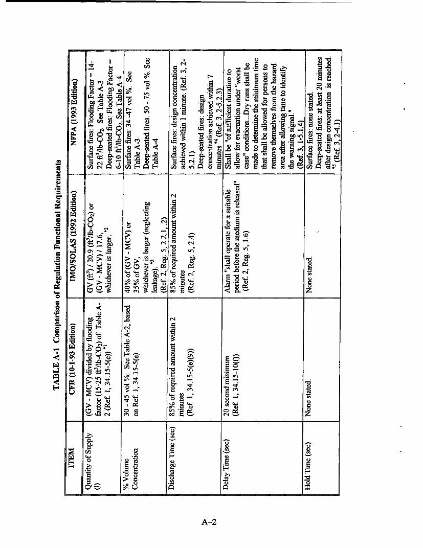
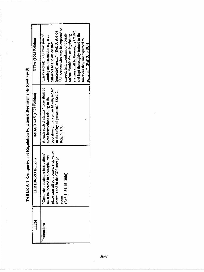
APPENDIX A:
Regulation Comparison Table
The total flooding carbon dioxide fire suppression system requirements according to the Code of
Federal Regulations (Ref. 1, Chapter 46, Subpart 34.15, 10-1-93 Edition), the International
Maritime Organization (Ref. 2, SOLAS, Chapter 11-2, Part A), and the National Fire Protection
Association (Ref. 3, NFPA 12, 1993 edition) have been compared. Additionally, the Factory
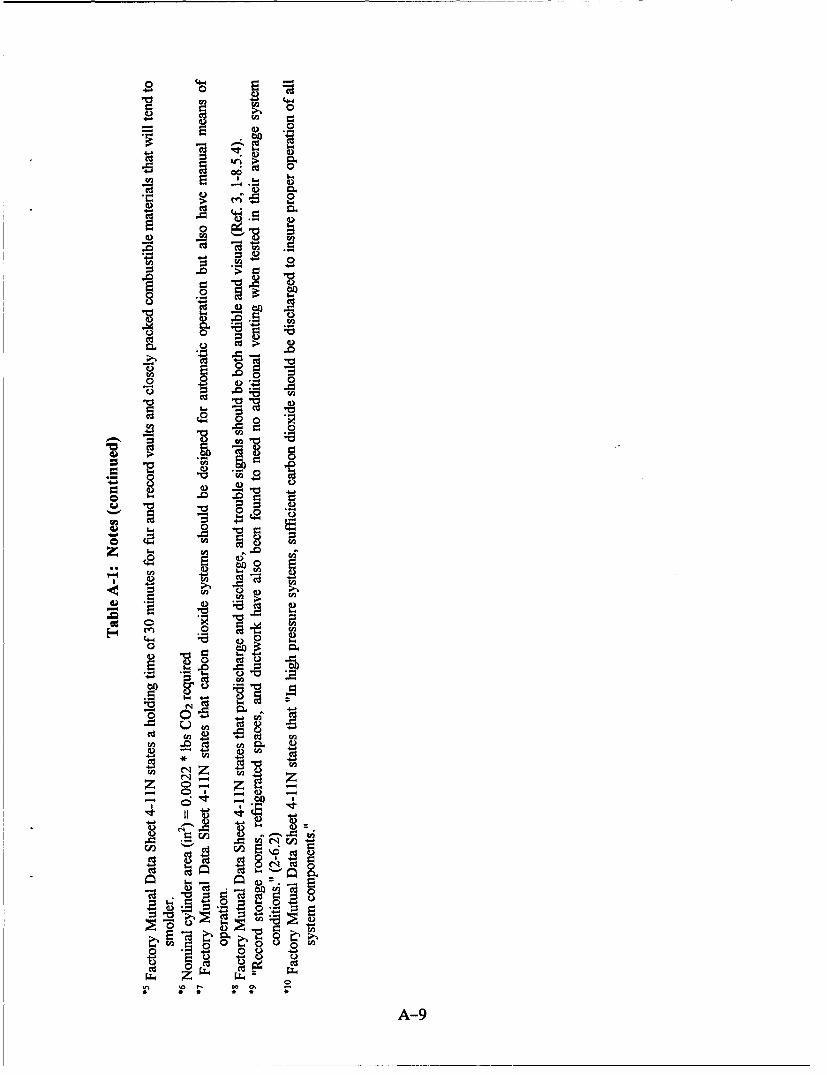
Mutual Engineering and Research Data Sheet 4-1 IN (Ref. 4) has been included via footnoted
differences to NFPA 12. These footnotes are listed following the table.
A-I
- 0 df
II '~z
to G-
44 1
0 0
00
o06o
00
0.
.6 f
____ 0
0
0.
44)
CY,)
C44)4
W4 44 4)4
4-i

ON)
0 0
4~4. 0 .*.0
_~~~ ~~ f0 ~ ~..~0
cdf
) 44 0 C.9
'a. S34 .
"o. 0>
oý 2
o ~ 00
A-3

"04-
o OR~-.
rqs W*-
78 0
o C',,
-, 8 -8 10
Aa00~ .0 N
C6 . "o 0 "
0.5 ) . EE ?- aDg -tA cd u~
Ho " ý30I U. 5
pr i0 0 0
7ý 2Z ýACo' -d O ~ 00- I - 04
'Ell CU
7ý
0C0
lu I UI. ~2t~*
-A-4

er' A
.U2-- 0 0
Ch 16 4. 2 0 ~ .-
-a Co0l w ,>0 o ~0 0
96 wa
z ~
~Q c
0 40. 0=-
000
E2 .2 tE~5 5
0 0 "
cu z
A-5

~~FoI~ ~ Ci2-
aO 4-i c,
Cw In"- 0ý 0t o. U .0 Q-
co
f4
&on
C'
C/)
VI e C
4.- *4~ -~44.-
e) .. 0 (A
-s
A-
4-~
4) . :
0 0 "4- .-
obON 5
AR 0
41
~4 0
A-7

.00
0,8 10
o~~~~~ W____________ s g
- .8 q- p
E! 0%0
o -a
0,4 4
-0 0~ tr-
4) 0,
rg 0 J.
z 40-
0 .0 ...
C- 0 1~0 0
C- 40.~ >
0 40. 49 C-
w 4-40 [,
-2 0 0 0-
0 . *0o________________________4___ 4S o (=Y-
'U2
0-
o l
A-8
""-40 - -0
4 0"
o = 0
40.0
CUd
w w 00
,a 4 r. -a
-3 - .21 9
-e C. 4
SA -9
• g• 0
CU z
-o -o
00A-9

Table A-2 USCG CO2 Factors
GROSS VOLUME *'(ft3) BUT NOT FLOODING CALCULATED %OVER: OVER: FACTOR VOLUME CONC.. 2
(ft3/lb C0 2 )
0 500 15 45.1
500 1,600 16 43.01,600 4,500 18 39.34,500 50,000 20 36.2
50,000 22 33.5Tankships contracted on/after GV 25 30.2
26MAY65; use whichever is
larger: above or...
• i Actually, GV - MCV, as discussed in footnote 1 of Table A-I.
•*2 Assuming one pound of CO2 expands to 9 cubic feet when released, the % volume
concentration of CO 2 (%C0 2) is calculated from:
volume of CO 2 added per volume of space = {log0o[100/(100-%C0 2)]/0.434}
A-10

Table A-3 NFPAIFM CO2 Factors: Surface Fires(NFPA/FM Table 2-3.3)
GROSS VOLUME BUT NOT FLOODING CALCULATED %(ft3) OVER: OVER: FACTOR VOLUME
(ft3/lb C0 2) CONCENTRATION'0 140 14 47.4
141 500 15 45.1501 1,600 16 43.0
1,601 4,500 18 39.34,501 50,000 20 36.2
50,000 22 33.5
"Assuming one pound of CO2 expands to 9 cubic feet when released, the % volume concentration
of CO2 is calculated from:
volume of CO2 added per volume of space = {log0o[l00/(100-%C0 2)]/0.434}
A-11

Table A-4 NFPA/FM CO2 Factors: Deep-seated Fires__LO__DING (NiPA/FMOTable 2-4.2.1)
DESIGN FLOODING HAZARD CALCULATED %CONC. FACTOR (ft3/lb CO2) VOLUME
CONCENTRATION*50 10 Dry electrical hazards in 59.3
general. (Spaces 0-2,000
f t).
50 12 (Spaces greater than 2,000 52.7
ft3).
65 8 Record (bulk paper) storage, 67.5
ducts and covered trenches.
75 6 Fur storage vaults, dust 77.7
collectors.
Assuming one pound of CO 2 expands to 9 cubic feet when released, the % volume concentration
of CO 2 is calculated from:
volume of CO 2 added per volume of space = {logio[ 100/(100-%C0 2)]/0.434}
A-12

Table A-5 CFR Branch Line Sizes (Reference 1, Table 34.15(e)(5))
Max. Quantity of Minimum Pipe Size Max. Quantity of Minimum Pipe SizeCarbon Dioxide (in) Carbon Dioxide (in)Required (bs) Required (bs)
100 V2 2,500 2 /2
225 3/4 4,450 3
300 1 7,100 3 ½2
600 1 ¼4 10,450 4
1,000 1 ½2 15,000 4 /2
2,450 2
A-13

[BLANK]

APPENDIX B:
CO2 System Failure Modes and Effects Analysis
A FMEA is a tabulation of failure modes of equipment and the resulting effects on a system or plant. It
generates a qualitative, systematic reference list of system components, failure modes, and their effects. A
detailed Failure Modes and Effects Analysis (FMEA) was performed for a high pressure CO 2 system in
three modes of operation; full discharge, standby, and installation test. The full FMEA tables for each of
these modes are listed at the end of this appendix.
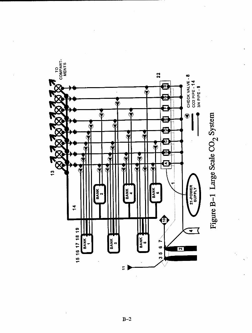
A high pressure CO2 system from a large modem cruise ship was utilized for the FMEA. A diagram of the
system is shown in Figure B-1. The principal dimensions of the ship are 218 meters length overall, 31 m in
beam, and a height above the keel of over 40 m (13 decks). There are eight engine room compartments
protected by the main CO 2 system. As indicated in Table B-i, these eight compartments are served by
various combinations of six banks of 100-lb CO2 cylinders. Activation alarms are sent to the bridge,
engineering control, and the compartments affected. The eight actuation valves for the various
compartments are contained in an enclosed control panel.
Table B-1. Zones of Operation
Zone Bank(s) Total Number of 40 Kg. C0 2 Cylinders
A. Aft Engine Room 1-2-3-4-5-6 91
B. Fore Engine Room 1-34-5 61
C. Engine Casing 1-3-6 59
D. P.E.M. Room 1-4-5 53
E. A.C. Compressor Room 1-3 36
F. Stabilizer Separator Room 2-4 27
G. Engine Control Room 3 8
H. E. G. Control Room 5 5
B-1
< -
0 CL
> W
-L
W 04
IL.
qe~
B-2~

Operating Mode
Operation of the CO2 system in response to a detected fire is described in Table B-2.
Table B-2. Procedure for Normal System Activation
1 Opening of the door on the actuation panel closes contacts on a limit switch that signalsvisual alarms in engineering control, the bridge and the spaces affected by that particularactuation panel.
2 Rotation of the gas release handle (Item 22 in Fig. B-i) for a given compartment on theactuation panel trips a limit switch that drives the relays for the pilot cylinder solenoidvalve, ventilation stop, and automatic door closing.
3 Pilot Cylinders (Item 2) are actuated by a solenoid valve (Item 6), and horns are activatedto warn occupants of the effected compartments.
4 CO2 from the pilot cylinders pressurizes the time delay cylinder (Item 4) over apreselected period of time (usually 35 seconds) to allow for the evacuation of the effectedcompartments.
5 After the time delay, the discharge hose (Item 9) becomes pressurized, and actuates theAutomatic/Manual directions valves (Item 13) opening the large diameter piping from themain CO2 banks to the compartment to be flooded. In addition, the cylinder valves (Item17) are actuated for the banks to be exhausted, allowing the necessary quantity of CO2 to
1 flood the compartment.
All the components are listed by part number within the FMEA for System Actuation, located in the tables
at the end of this appendix.
Standby Mode
Standby mode is the mode that the system is in for the majority of its operating life. It is the mode in which
the system is basically "asleep", waiting to be used.
B-3

Testing
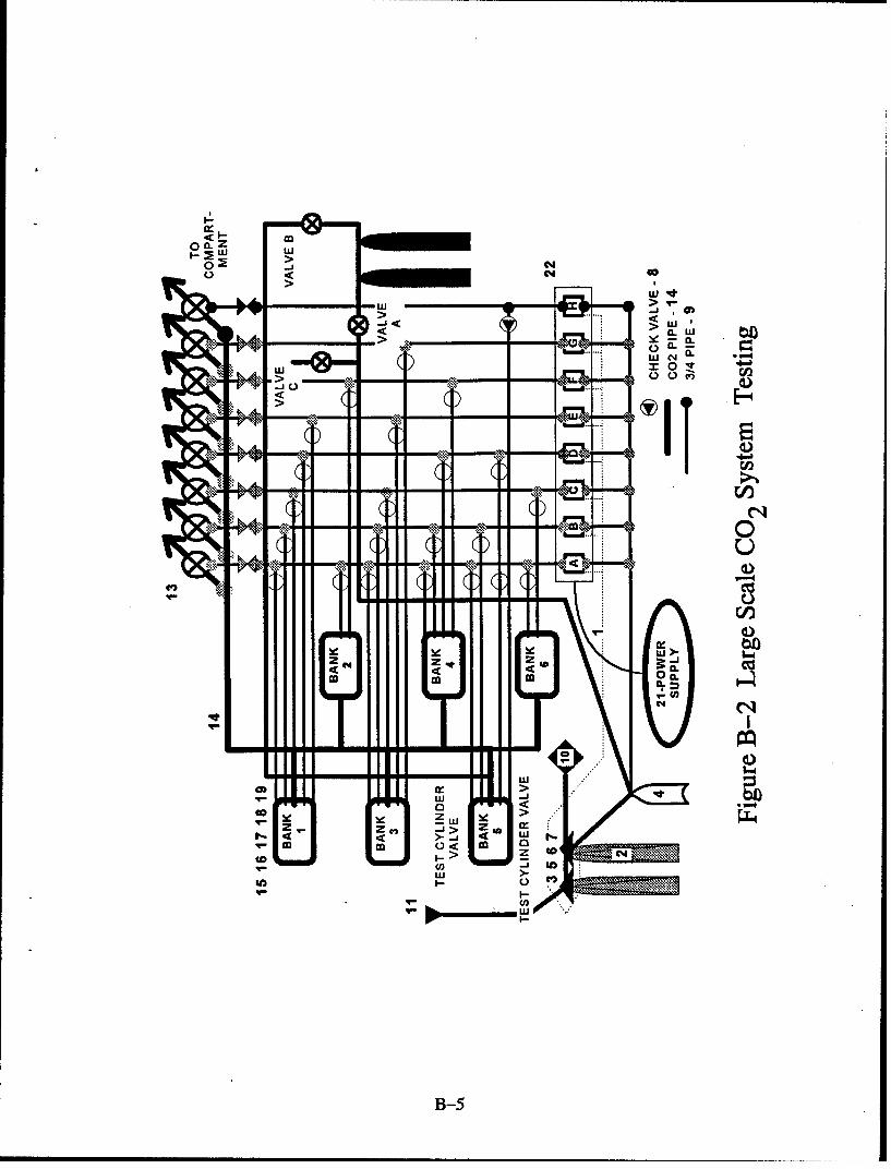
In order to perform this test, the system was modified by disconnecting the bank of CO2 cylinders and
connecting temporary cylinders, as well as three valves. This is shown in Figure B-2. These cylinder
typically contain much less C0 2 than the banks do. These tests are just used to "blow the pipes down", and
insure that the multiple actuation valves are working properly. The test procedure is described as follows
Preparation for the Test
As the ship studied called on U.S. ports, a Coast Guard procedure was prescribed, and is shown below in
Table B-3.
Table B-3
Preparation for Test1 A, B and C temporary valves to be closed.2 Pilot cylinders (Item 2) electronically disconnected.3 Disconnection of the existing flexible hose of the pilot cylinders (Item 3).4 Connection by 10mm alloy pipe, between the temporary CO2 test cylinders, the pilot
cylinders and the main CO2 cylinder banks line.5 For safety reasons, the flexible hoses (items 3 and 16) of the CO2 copilot cylinders and banks
are to be disconnected.
Phase 1 of Testing1 Opening of temporary CO2 test cylinders.2 Opening of the valve in the actuation station (Items 1 and 22) relevant to the chosen room.3 Opening of the A temporary valve to simulate release of CO 2 from the pilot cylinders.4 Checking the pneumatic time delay (Item 4) of the relevant copilot pistons and of the relevant
direction valve (Item 13).
Phase 2 of Testing
1 After the phase 1 checking, opening the B temporary valve.2 Checking the CO2 discharge in the chosen room3 Closing the A and B valves at the end of testing.
Phase 3 of Testing
1 After the conclusion of phase 2, opening of the C temporary valve to discharge the residualC0 2 from the pipes
2 Reset the open pistons of the copilot cylinders3 Connection of all the released pipes and valves.
B-4
<
Oo Z
~LU4 _ __ __ -a. w
L) a.
w C144a
7 c%4 ut :m 0-4
cr~
m
CO4)
B-5

The FMEA Procedure
The columns of the full FMEA tables included the following information:
Table B-4
1 Item number and name2 Operating condition of item in given operating scenario Is the item normally open or closed?
On or off? This is only for the condition in which the system is operating.3 Failure modes. This is a description of how the equipment fails (open, closed, on, off, leaks,
etc.).4 The cause of failure.5 The possible effects of failure on the system.6 Criticality of the failure. How important is it?7 Possible action to reduce failure rate or effect.
A diagram of the system studied is shown in Figure B-1. An example is given to explain how the various
columns listed above were developed. This is a description of the FMEA for Item 13, the automatic/manual
directions valves, is shown below in Table B-5.
B-6

Table B-5
Operating condition of item in given operating scenario: Normally open when the system is actuated.
Failure modes:
Partially obstructedFully obstructed
Cracking (housing)Packing failureManually open to wrong compartment
Cause of failure
IPartially obstructedImproper manufactureImproper installation
IFully obstructedI Improper manufactureImproper installation
[Cracking (housing)Improper manufactureImproper installation
Packing failureImproper manufactureImproper installation
1Manually oEn to wrong compartmentFailure to reset after a test
_Operator opens wrong valve
Possible effects of failure on system
Reduced flow rateNo CO 2 deliveredReduced flow quantity/No flowReduced flow rate! No flow
Criticality
All of these types of failure were deemed to be primary, due to the potential for eitherno flow of CO2 or the potential for exposure of the crew to CO 2 and the resultingdanger that this imposes.
Possible Action to Reduce Failure Rate or Effect.
For most of these problems, regular inspection, proper operating procedure or regularflow testing will result in a minimization of risk.
B-7

A component was considered of primary concern if its failure in operation led to a complete failure of the
system to extinguish the fire, with no possibility of the component being bypassed so that its failure would
be of less consequence. A component was also considered to be of primary concern if its failure threatened
the life of the crew or passengers. A component was considered of secondary importance if its failure in
operation might result in a change in standard operating procedure of the system, but whose failure could
be bypassed in some way.
Conclusions
It appears that many of the mishaps listed above can be remedied by following regular inspection and
testing procedures. There seems to be a very real potential for incorrectly opening a manual valve which
will admit CO2 into an occupied, unwarned compartment full of CO 2, and in fact situations like this do
occur. For the primary concern, failure in full discharge mode, two of those components have failure
modes that could prevent any CO2 from being delivered into the intended machinery space. It is apparent
that these failure modes occur directly from obstructions in the CO2 delivery system. Four other
components have failure modes that could result in significantly reduced CO2 concentrations in the
machinery space. Two other components (directional valves and control panel switches actuating these
valves) have failure modes that could prevent CO2 from being discharged and/or could allow discharge into
an unintended, occupied area.
B-8

APPENDIX C
CO2 System Pipe Length Limitations
The effectiveness of fixed CO2 fire extinguishing systems in combating fires is a function ofnumerous variables. Some of the more important ones include: design CO 2 concentration,discharge time, distribution of the CO2 within the protected space, and hold time. Fire codes andbodies of regulation attempt to address these variables in different ways. This appendix considerswhether Coast Guard Regulations (46 CFR) are sufficient (when compared to NFPA 12) toensure uniform distribution of the CO 2 within the protected space, especially when faced withdistribution piping of varying lengths.
Coast Guard regulations for fixed CO2 systems (46 CFR 34.15-5(e)) specify that "The number,type and location of discharge outlets shall be such as to give a uniform distribution throughoutthe space." NFPA 12 specifies that discharge nozzles must be located to "achieve the bestresults" (NFPA 12 2-5.5). The reader must assume that "achieving the best results includesensuring a uniform distribution of CO2 within the space.
To achieve uniform distribution of CO2 within the protected space, the CO 2 must be uniformlydistributed both vertically and laterally. Lateral distribution is primarily affected by the numberand location of nozzles. Vertical distribution is affected by the number and location of nozzles,and the degree to which the CO2 mixes with the ambient air. In cases where there is poor mixing,the cold CO 2 forms a discrete mass of gas which is heavier than the ambient air. Under theseconditions, settling of the CO2 to the bottom of the compartment may be expected. In instanceswhere the mixing in the vicinity of the nozzle is good, the density difference between the incoming(mixed) gas and the ambient air is low and stratification within the space is minimized.
Neither 46 CFR nor NFPA 12 offer any more concrete guidance concerning the lateraldistribution of the CO 2 than the above, general, uniform distribution requirement; determining thenumber and spacing of nozzles is left to the designer. NFPA 12 does provide some guidancetoward achieving vertical distribution where 46 CFR does not. NFPA 12 requires that thepressure drop across the distribution nozzles be at least 300 psi (2068 kPa) for high pressuresystems, and 150 psi (1034 kPa) for low pressure systems. Pressure drops of these magnitudesare assumed to be sufficient to ensure significant turbulent mixing in the area of the nozzle.
It is, at this point, worthwhile to consider whether the pressure drop requirement in NFPA 12actually results in more uniform vertical distribution of CO2 when compared to 46 CFR systems.Criteria for high pressure systems are used because high pressure systems are much morecommon than low pressure systems in marine use. To make this comparison, two issues must beconsidered. First, the 300 psi specified in NFPA 12 does not represent a mixing "cutoff' (i.e.,mixing at higher pressures, no mixing at lower pressures). 300 psi is that pressure deemed by theNFPA to produce sufficient mixing. Second, pressure drop across the nozzle is not a variablewhich can be controlled independently. The pressure drop is a function of initial storage pressure
C-1

(assumed to be 750 psi (5170 kPa) which is the vapor pressure of liquid CO 2 at 700F (21°C)), thepiping geometry (length and diameter) and the orifice diameter.
While it is the intent of this analysis to compare the abilities of 46 CFR and NFPA 12 to ensureuniform CO2 distribution, in fact it is only comparing pressure drops through the nozzles. Thesepressure drops may only be considered an indicator of CO2 distribution. Ensuring uniform CO2
distribution within a space would require either a fully validated 3D mathematical model or 3Dpost installation CO 2 concentration testing. Neither 46 CFR nor NFPA 12 requires these steps.
The analysis is conducted using system sizing information contained in 46 CFR 34.15-5(Table C-i) and pressure drop calculations contained in NFPA 12. The NFPA required pressuredrop of 300 psi will be used to determine equivalence. The analysis will be conducted in twosections. The first section will consider whether systems which discharge as slowly as permittedby Coast Guard Regulations (85% of the required CO2 within 2 minutes) meet the NFPA pressuredrop requirement. The second section will consider the maximum length of distribution pipingthat will produce a pressure drop at the nozzle of at least 300 psi. English units will be usedthroughout the analysis in keeping with the units used in the CFR. The subscripts min and maxwill be used throughout the following calculations. In all cases the subscript min is associatedwith values derived from the minimum permissible orifice area. The subscript max is associatedwith values derived from the maximum permissible orifice area.
Table C-i
System Size (W) (lb) 300 2500 10450Orifice Size min max min I max min I maxNominal Pipe Dia. (in) 1 2.5 4Inside Dia. (ID) (in) .957 2.32 3.83ID1.2 5 .946 2.86 5.34ID2 .916 5.40 14.6Flow Rate (Q) (lb/min)* 128 1063 6375Orifice Area (in2 ) .23 56 1.93 4.68 8.05 19.5Spec Flow Rate (g) 554 228 550 227 552 227
(lb/min/in2)**
* Q=W* 85% / 2.in
** qm = Q min orifice area** q = Q I max orifice area
Graph C-I was derived from the pressure drop/flow information for high pressure systemscontained in NFPA 12 table 1-10.4.4. From the graph it can be seen that a specific flow rate (q)of 980 lb/min/In2 is necessary to create the 300 psi pressure drop required by NFPA 12. Since
qmin (approx 552 lb/min/in 2) and qmax (227 lb/min/in 2 ) from Table C-I are significantly less than
C-2

980 lb/min/in2, it should be apparent that a CO 2 system operating at the minimum delivery rate
required by 46 CFR can never meet the NFPA pressure drop requirement.
Graph C-i
5000
.E 4000C
3000.0
'm 2000
1000-
0*0 200 400 600 800
Pressure Drop (psi)
The basis for the second part of this analysis is that the actual discharge rate for a system is afunction of both orifice size and pipe geometry and, as a result, the actual discharge time may besignificantly less than the maximum permitted by regulation. It can be seen from Graph C- I that ifthe discharge rate increases (discharge time decreases) that the pressure drop across the nozzleincreases. It is therefore possible for a system designed to 46 CFR specifications to meet theNFPA 300 psi pressure drop requirement.
Determining the conditions under which a system will discharge at a sufficient rate to meet thepressure drop requirement requires that two conditions be simultaneously satisfied. The firstcondition is that the total pressure drop in the system (Pr) is 750 psi. This pressure drop is
produced by two components, the pressure drop through the orifice (P.) and the frictionalpressure drop of the fluid flowing through the distribution piping (Pf) as shown in Equation 1.
PO +Pf~Pt750 psi Equation 1
The second condition which must be satisfied is that the flow rate (Q) through the nozzle and thepipe must be equal. This flow rate is an implicit function of P0 and Pf as shown in Equations 2 and3.
P0 =ffQ, orifice area) Equation 2
C-3

Pf =J(Q, pipe length, pipe diameter) Equation 3
Ideally, the discharge characteristics of a system could be fixed by the simultaneous solution ofthese three equations. In practice, the complexities of these functions requires the employment ofGraphs C-I and C-2 to solve for Po, Pf and Q.
Just as in the first section of this analysis, if 300 psi is selected as the critical pressure dropacross the nozzle, Graph C-I indicates that the specific flow rate will be equal to 980
lb/min/in2. Prior to entering Graph C-2, the specific flow rate must be converted to an actualflow rate (Q) (lb/min) (Table C-2) through the use of the minimum and maximum orificeareas. The calculated Q values along with the pipe diameter information contained inTable C-I and a terminal pressure of 300 psi may be used to enter Graph C-2. The terminalpressure is the pressure at the end of the piping system. It is equal to the pressure dropthrough the orifice since the pressure of the gas after passing through the orifice is 0 psig.
Table C-2. INPUT FOR GRAPH C-2
System Size (W) (lb) 300 2500 10450Orifice Size Min M Max MMin MaxNominal Pipe Dia. (in) 1 2.5 4Inside Dia (ID) (in) .957 2.32 3.83192 .916 5.40 14.6Orifice Area (in2) .23 .56 1.93 4.68 8.05 19.5Spec Flow Rate (g) 554 228 550 227 552 227Qact.a (lb/min)* 225 548 1891 4586 7889 19149Qact.a (ID2) 246 599 350 849 539 1307Terminal Pressure (psi) 300 300 300
* Qactuai = 980 lb/min/in * orifice area (max or min)
The output from Graph C-2 is the equivalent length of pipe required to cause the pressure in thepiping system to drop from the storage pressure (750 psi) to the terminal pressure (300 psi).Table C-3 contains two sets of equivalent pipe length information. These lengths correspond tothe minimum allowable orifice area (L.(ni)) and the maximum allowable orifice area (L.(,). Theequivalent length of pipe consists of the actual length of straight pipe plus additional lengths fortees, elbows, and other fittings. Pipe lengths shorter than those listed in Table C-3 will yieldhigher flow rates, higher pressure drops through the nozzles, and shorter actual discharge times.Conversely, longer pipe runs will result in lower flow rates, lower pressure drops through thenozzle, and longer discharge times.
C-4

00e, 014.4
00o0
-.. Oo Ow
40.
1-00"
lelsd vi ain~sosd leu~wij.l
C-5
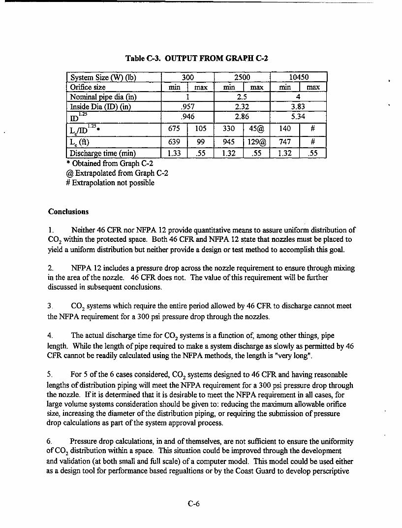
Table C-3. OUTPUT FROM GRAPH C-2
System Size (W) (lb) 300 2500 10450Orifice size min jmax min I max inNominal pipe dia (in) 1 2.5 4Inside Dia (ID) (in) .957 2.32 3.83ID1.25 .946 2.86 5.34
L/ID *125 675 105 330 45@ 140
Le (ft) 639 99 945 129@ 747
Discharge time (min) 1.33 .55 1.32 .55 1.32 .55* Obtained from Graph C-2
@ Extrapolated from Graph C-2# Extrapolation not possible
Conclusions
1. Neither 46 CFR nor NFPA 12 provide quantitative means to assure uniform distribution ofCO2 within the protected space. Both 46 CFR and NFPA 12 state that nozzles must be placed toyield a uniform distribution but neither provide a design or test method to accomplish this goal.
2. NFPA 12 includes a pressure drop across the nozzle requirement to ensure through mixingin the area of the nozzle. 46 CFR does not. The value of this requirement will be furtherdiscussed in subsequent conclusions.
3. CO2 systems which require the entire period allowed by 46 CFR to discharge cannot meetthe NFPA requirement for a 300 psi pressure drop through the nozzles.
4. The actual discharge time for CO2 systems is a function of, among other things, pipelength. While the length of pipe required to make a system discharge as slowly as permitted by 46CFR cannot be readily calculated using the NFPA methods, the length is "very long".
5. For 5 of the 6 cases considered, CO2 systems designed to 46 CFR and having reasonablelengths of distribution piping will meet the NFPA requirement for a 300 psi pressure drop throughthe nozzle. If it is determined that it is desirable to meet the NFPA requirement in all cases, forlarge volume systems consideration should be given to: reducing the maximum allowable orificesize, increasing the diameter of the distribution piping, or requiring the submission of pressuredrop calculations as part of the system approval process.
6. Pressure drop calculations, in and of themselves, are not sufficient to ensure the uniformityof CO2 distribution within a space. This situation could be improved through the developmentand validation (at both small and full scale) of a computer model. This model could be used eitheras a design tool for performance based regualtions or by the Coast Guard to develop perscriptive
C-6

codes. Alternatively, a post installation discharge test which measures the CO2 concentration in
three dimensions could be imposed.
C-7

[BLANKI

APPENDIX D
Summaries of Representative C0 2 System Problems in Selected Incidents
Machinery space fire incidents which involved a CO2 suppression systems discharge that resulted in
extinguishing the fire are not discussed. Only those CO2 discharge incidents which resulted in the fire being
temporarily extinguished, controlled, or not extinguished are summarized below. All quotes are taken from
the accident reports and are not referenced. Authors' comments are provided for each incident described.
D. 1 Enerchem Asphalt
An explosion in the engine room blew open an engine room door. Upon locating the resulting fire,
the chief engineer ordered the dampers in the funnel, the ventilation system, and all the doors into the engine
room closed down. The chief engineer then discharged the CO2 extinguishing system, approximately ten
minutes after the fire started. However, a small amount of smoke was observed escaping through air vents
and around the funnel. Thus, the engine room was not completely sealed. When shore-based fire fighters
entered the engine room, they observed that the fire had re-ignited with "great" intensity.
Authors' Comment: Most likely the reason for not being able to seal the engine room is due to the
initial explosion deforming the doorjamb, and possibly any other closed vent at the time. When an attempt
was made to close the door after the explosion, it did not completely seal. Therefore, after activation of the
CO2 system some CO2 leaked out. This leakage together with the dilution associated with the fire fighter's
entry into the engine room resulted in an insufficient concentration to suppress the fire.
D.2 Protector Alpha
Fuel oil overflowed a diesel tank and was ignited by contact with the exhaust manifold of a ship's
service generator. A subsequent explosion blew open the centerline door. A period of 45 to 55 minutes
after the fire started was required for search and rescue efforts before the C0 2 system was activated.
Additionally, this vessel was manned by Filipinos and had Greek owner's representatives onboard at the
time of the fire. The instructions for the CO2 system were written in German. No one onboard at the time
of the fire could read the CO2 instructions.
Authors' Comment: This incident has two points. The first is that the instructions for the CO2
suppression system must be written in a language all crew members can understand. The second point is
that even if the engine room had been sealed, the effectiveness of the CO2 would probably have been
D-1

limited since the fire was allowed to grow for at least 45 minutes after ignition. This size fire presents a
high challenge to a CO2 system.
D.3 Mara Hope
This fire started in the engine room bilge at approximately 1850 while the vessel was moored at a
repair facility. A shore-based fire department responded and firefighters were told upon their arrival, at
1909, that people were trapped in the engine room. Search and rescue efforts resulted in no persons being
found in the engine room. At 1930 the fire department was notified that all personnel were accounted for
and they began pumping foam into the engine room. Since the foam was not effective, the vessel's fixed
C0 2 system was activated. The C0 2 system was not effective due to the engine room not being sealed.
The fire burned for about 41 hours before being extinguished with high expansion foam.
Authors' Comment: Like the previous case, if the engine room had been properly sealed prior to
discharge, the C0 2 most likely would not have had limited effectiveness due to the length of time between
ignition and activation of the CO2 system; more than 40 minutes in this case.
D.4 Saratoga
Apparently, a hydraulic pump hose ruptured and sprayed hydraulic fluid onto the casing of a diesel
engine thus igniting a large spray fire. The chief engineer pulled the releasing gear for the fixed C0 2 fire
extinguishing system. No crew members saw any C0 2 escaping from the engine room or heard the audible
C0 2 alarm. Therefore, "the C0 2 fire extinguishing system either malfunctioned or failed to activate."
Authors' Comment: This is the only incident (out of 17 incidents described in this appendix) in
which the CO2 system failed to discharge upon an activation attempt.
D.5 Maersk Oakland
The fire was discovered at 2336. After fighting the fire with portable extinguishers, the fire was
declared out of control at 2343. At 0010 "All but one of the ventilation sources to the space were then
secured. The mechanical means of securing the ventilation ducts near the top of the main stack did not
function properly. Tarpaulins were used to partially block this ventilation source into the engine room."
The fixed C0 2 system was activated at 0120 under the supervision of a shore-based fire department. "The
C02 system did not completely extinguish the blaze..."
Authors' Comment: Since this fire burned for one hour and 40 minutes before the C02 system was
activated, there may have been fire damage to various closures including tarpaulins.
D-2

D.6 Princess Tamara
"About 0600 a fire broke out on the main electrical switchboard in the engineroom. The fixed CO2
fire extinguishing system which protected the engineroom was activated, but it did not extinguish the fire
because the crew opened hatches to the engineroom shortly after the CO2 was released." The report states
that this allowed fresh air to enter the engine room and thus supplied the fire with oxygen.
Authors' Comments: This is an obvious case of improper training or negligence since the CG
regulations require closure of all ventilation onpenings.
D.7 Curlew
A fire was discovered about 0600 that engulfed "the entire port side of the engineroom". A
crewmember "notified the master who operated the remote release for the fixed CO2 system in the
engineroom. The engineroom vents were left open." The CURLEW burned and sank.
Authors' Comments: Ostensibly, the ventilation was not secured. The question is whether this was
due to improper training or due to somebody panicking and forgetting to secure the engine room ventilation.
D.8 Madelyn G.
About 1530 a fire was discovered in the engine room and "there were flames throughout the
bilges." The chief engineer said, "after waiting a few minutes to allow everyone to "get clear", he released
the C0 2". "...the ventilation blowers were probably turned off by the release of the CO2. However, a hatch
in the upper level of the engineroom had been left open,..."
Authors' Comment: Another case of not securing the ventilation before discharging the CO2 .
D.9 American Queen
Fire was discovered about 1730. "About 1750, the chief engineer released the CO 2 into the
engineroom and secured the engineroom door." No flames were seen when the engine room door was
opened at 1830. Flames were observed at 1900 when the engine room was again checked. At this point the
vessel was abandoned and subsequently sank.
Authors' Comment: This is an example of a possible re-ignition due to the opening of a door
allowing air entry and CO2 dilution.
D-3

D.I0 Charleston
A lube oil leak occurred during unsupervised and unscheduled work on lube oil pressure gauges.
The lube oil spray contacted the steam turbine casing and ignited. "The fire quickly spread from the
turbogenerator to the upper level of the engineroom. Initial firefighting attempts with portable CO 2
extinguishers were unsuccessful and the intensity of the fire increased. After evacuating the engineroom
and accounting for crewmembers, the fixed CO2 system was activated. The fire was extinguished by the
exhaustion of the lube oil supply."
Authors' Comment: Besides the delayed actuation time, another important factor in this fire may
have been an insufficient C0 2 concetration in the upper region of the engine room.
D.11 Luiua
A lube oil spray fire resulted from negligence of a crew member. This incident has both a letter
report and a Coast Guard vessel accident report (CG-2692). The letter report states: "The fire was
extinguished by shutting down the main engine and flooding the engineroom with carbon dioxide." The
vessel accident report states: "The engine room was then evacuated and the CO2 system was then put into
use to try and put the fire under control. CO2 fire extinguishers were also used to bring the fire under
control."
Authors' Comments: The description of this incident is too cursory to determine the true
effectiveness of the CO2 system. It appears that the fixed C0 2 system controlled the fire sufficiently to
allow the crew to fully extinguish the fire with portable extinguishers.
D. 12 Fidelity
Fire discovered at approximately 1945. When the fire was declared out of control, the main
engine, the generator, and the engine room mechanical ventilation were shut down. Prior to 2009, all
personnel were evacuated from the engine room and all ventilation dampers and entrances to the machinery
space were closed. The master then activated the fixed CO 2 system. At 2200 the machinery space was
checked for flames. Small pockets were found and the space was "immediately vacated and again sealed."
"At 2400 the fire was found to be completely extinguished..."
Authors' Comment: Difficult to assess this scenario. It appears that all the proper steps were
taken prior to the release of the fixed CO 2. This case is listed as a "controlled" fire due to the time between
D-4

when the C0 2 was released and when the space was checked, about two hours. The C0 2 did not fully
extinguish the fire after two hours, but it decreased the size of the fire so that it was no longer a threat to
personnel or equipment.
D.13 Boheme
Fire in the machinery space reported at 1307 onboard this cruise ship while moored and embarking
passengers. Passengers were ordered to disembark and by 1315 had done so. Also at that time the master
remotely closed the engine room door and ordered the manual fire dampers closed. Shore-based fire
department arrived at 1320. At 1345 "...CO 2 cylinders specified for the auxiliary engineroom and control
room were released ...". "The initial application of CO2 did not extinguish the fire. At 1355, the CO2
cylinders specified for the main engine room were diverted to the auxiliary engine room. While the second
application temporarily reduced the flames it did not totally extinguish the fire."
Authors' Comment: It is not clear why the CO2 discharge did not extinguish the fire, but an earlier
actuation would probably have been more effective.
D.14 Neoga
Straight forward; from the accident report: "The CO2 system had little effect in containing or
extinguishing the fire because the crew had failed to close engineroom accesses and vents in order to seal
off oxygen to the fire." This fire also involved a fuel tank that had no external shut off valve. Thus, the
fire burned for almost five days before consuming all the fuel.
Authors' Comment: From the accident report, this appears to have been a fast moving fire, with a
CO 2 system discharge into an engine room with open vents and doors.
D. 15 Weiho Career
Fire started about 0350 while the vessel was moored. Fire department arrived at 0403 and ordered
all personnel off the vessel. Subsequent to the evacuation, "the engineroom CO2 fire extinguishing system
was activated, but it failed to extinguish the fire." "At 0700, additional CO2 supplied by trucks on shore
was applied to the engineroom. About 20 minutes later, foremen entered the deckhouse and extinguished
the fire."
Authors' Comment: No mention is made of the status of the ventilation openings, etc., so it is not
clear why the CO2 wasn't more effective.
D-5

D.16 Jack D. Wofford
Heavy black smoke was observed coming from the engineroom. The engineer "stopped both main
engines, exited and closed the engineroom door and discharged one bank of CO2 bottles into the
engineroom." Ten minutes later he checked the engineroom and found heavy black smoke. He left the
engine room and "discharged the last bank of CO2 bottles into the space. The fire was still not completely
extinguished and had traveled up the bulkhead and through the electrical cable runs...".
Authors' Comment: Factors contributing to the limited effectiveness of the C0 2 system in this fire
appear to be: 1) premature opening of the engine room to see if the fire was out; 2) flame propagation into
the upper region of the engine room where CO2 concentrations may be reduced; and 3) ineffective cable
penetration stops.
D. 17 Scandanavian Sun
As this cruise ship was preparing to disembark passengers after docking, a fire started in the
auxiliary machinery space at about 2300. The report notes "the failure of the crew...to keep closed the
watertight door and the self-closing fire door...". However, the master had ordered closed all automatic fire
doors and stopped all ventilation fans at 2312. After 2324 the chief engineer released CO 2 "into what he
thought was the [auxiliary machinery space]. Five days later Coast Guard investigators determined that the
CO2 had been released into a room not involved in the fire.
Authors' Comment: According to the CG report, the most likely reason the CO2 was released into
the wrong space is because the release mechanisms for the CO2 systems were not adequately labeled.
D.18 Zorra
This was an engine room diesel fuel fire on the U.S.-flagged integrated tug-barge Zorra moored at a berth
in Guanica Bay, Puerto Rico. According to the account in the August 1995 issue of Professional Mariner,
crew "responded quickly to the fire by sealing off the engine room and activating the CO2 system." Puerto
Rican firefighters, assisted by the crew, attempted extinguishment for more than 12 hours before declaring
the fire unmanageable. At that point, the Coast Guard was concerned about the fire igniting dockside
tanks, and decided to tow the vessel away from the dock and ground it outside the shipping channel. The
vessel was a total loss.
D-6

Author's Comments: Although the report said the engine room was sealed, it also describes a thick, black
smoke plume engulfing a nearby school. It is not clear how long the engine room was sealed before the
plume was observed. It is also not clear if there was any confirmation of the C0 2 system discharging, and
how long firefighters waited before entering the engine room for manual firefighting.
D-7


