

RESOURCE ASSET RESOURCE ASSET REGISTRATION FORMREGISTRATION FORM WORKSHOPWORKSHOP
Generation Resources Generation Resources –– NonNon--WindWind
March 13, 2008March 13, 2008

Resource Registration2
LEGAL DISCLAIMER & ADMONITIONLEGAL DISCLAIMER & ADMONITION
ANTITRUST ADMONITIONERCOT strictly prohibits market participants and their employees, who are participating in ERCOT activities, from using their participation in ERCOT activities as a forum for engaging in practices or communications that violate antitrust laws. The ERCOT Board has approved Guidelines for Members of ERCOT Committees, subcommittees, and working Groups to be reviewed and followed by each market participant attending ERCOT meetings. If you have not received a copy of these Guidelines, please take one now, review it at this time, and remember your ongoing obligation to comply with all applicable laws, including antitrust laws.

AGENDAAGENDA
Resource Registration4
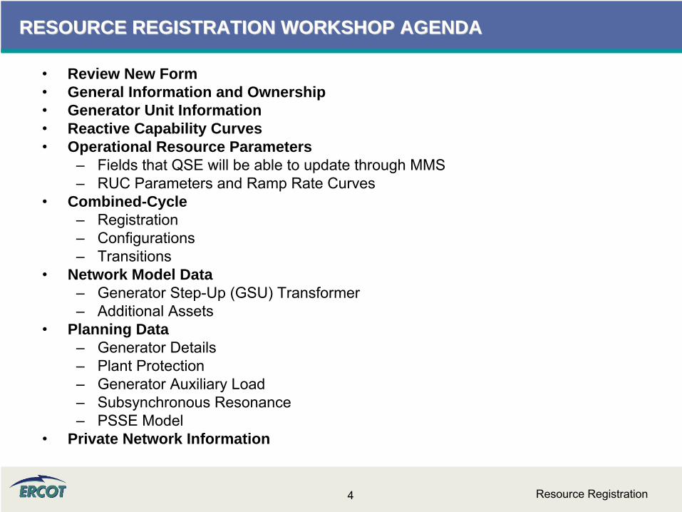
RESOURCE REGISTRATION WORKSHOP AGENDARESOURCE REGISTRATION WORKSHOP AGENDA
•
Review New Form•
General Information and Ownership•
Generator Unit Information•
Reactive Capability Curves•
Operational Resource Parameters–
Fields that QSE will be able to update through MMS–
RUC Parameters and Ramp Rate Curves•
Combined-Cycle –
Registration–
Configurations–
Transitions•
Network Model Data–
Generator Step-Up (GSU) Transformer–
Additional Assets•
Planning Data–
Generator Details–
Plant Protection–
Generator Auxiliary Load–
Subsynchronous Resonance–
PSSE Model •
Private Network Information

NEW FORM NEW FORM -- SAMPLESAMPLE
Resource Registration6
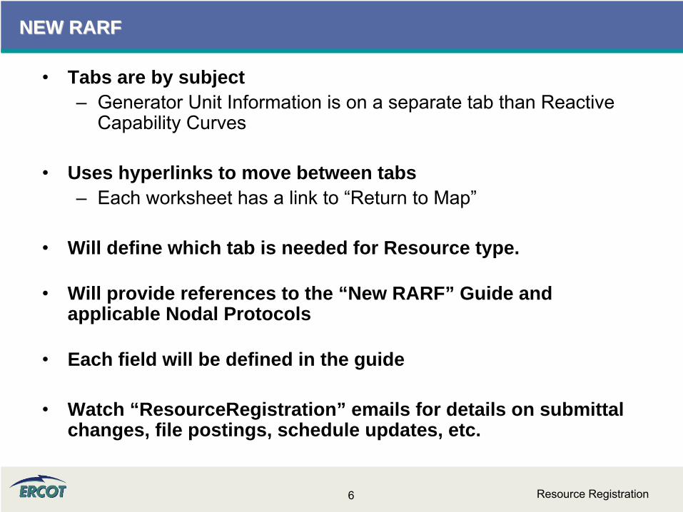
NEW RARFNEW RARF
•
Tabs are by subject–
Generator Unit Information is on a separate tab than Reactive Capability Curves
•
Uses hyperlinks to move between tabs–
Each worksheet has a link to “Return to Map”
•
Will define which tab is needed for Resource type.
•
Will provide references to the “New RARF” Guide and applicable Nodal Protocols
•
Each field will be defined in the guide
•
Watch “ResourceRegistration” emails for details on submittal changes, file postings, schedule updates, etc.

Resource Registration7
NEW RARF NEW RARF –– MAP AND NAVIGATIONMAP AND NAVIGATION

Resource Registration8
NEW RARF NEW RARF –– REACTIVE CAPABILITY CURVE SAMPLEREACTIVE CAPABILITY CURVE SAMPLE

Resource Registration9
NEW RARF NEW RARF –– UNIT INFORMATION SAMPLEUNIT INFORMATION SAMPLE

GENERAL INFORMATION AND GENERAL INFORMATION AND OWNERSHIPOWNERSHIP

Resource Registration11
GENERAL INFORMATIONGENERAL INFORMATION
•
Submittal Information–
Date format shall be MM/DD/YYYY–
Resource Entity name must match ERCOT’s record–
DUNS number is either a 9 digit or 13 digit number
•
Resource Entity Authorized Representative–
As registered with ERCOT–
Responsible for submission of RARF to ERCOT
•
Primary Contact–
Site or facility contact for Generation Resources–
Resource Entity contact for Load Resources–
May be Authorized Representative

Resource Registration12
GENERAL INFORMATIONGENERAL INFORMATION
•
Site info for Generation Resources–
This section does not apply to Load Resources or Block Load Transfers
–
Resource Site Name/Code to be determined jointly with ERCOT
–
Site In-Service Date is the date when plant was commissioned
–
Indicate CMZ where Resource is located.
–
Indicate if Resource is owned by a NOIE and metered
–
Identify TDSP providing service–
Confirm metering scheme and quantity
–
Identify if Generation Load splitting
Resource Registration13
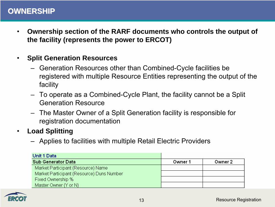
OWNERSHIPOWNERSHIP
•
Ownership section of the RARF documents who controls the output of the facility (represents the power to ERCOT)
•
Split Generation Resources–
Generation Resources other than Combined-Cycle facilities be registered with multiple Resource Entities representing the output of the facility
–
To operate as a Combined-Cycle Plant, the facility cannot be a Split Generation Resource
–
The Master Owner of a Split Generation facility is responsible for registration documentation
•
Load Splitting–
Applies to facilities with multiple Retail Electric Providers

GENERATOR UNIT INFORMATIONGENERATOR UNIT INFORMATION

Resource Registration15
GENERATOR UNIT INFORMATIONGENERATOR UNIT INFORMATION
•
All Generation Resources will have to fill out a Generator Unit Information Tab–
Resource Unit Name & Code to be determined jointly with ERCOT–
Start Date and End Date should be formatted MM/DD/YY

Resource Registration16
GENERATOR UNIT INFORMATIONGENERATOR UNIT INFORMATION
•
CA = Combined-Cycle steam part (includes steam part of integrated coal gasification combined-cycle)
•
CC = Combined-Cycle total unit (use only for plants/generators that are in planning stage, for which specific generator details cannot be provided)
•
CE = Compressed air energy storage•
CS = Combined-Cycle single shaft (combustion turbine and steam turbine share a single generator)
•
CT = Combined-Cycle combustion turbine part (includes combustion turbine part of integrated coal gasification Combined-Cycle)
•
FC = Fuel Cell•
GT = Combustion (gas) turbine (includes jet engine design)
•
HY = Hydraulic turbine (includes turbines associated with delivery of water by pipeline
•
IC = Internal combustion (diesel, piston) engine
•
NA = Unknown at this time (planned units only)
•
OT = Other•
PS = Hydraulic Turbine -
Reversible (pumped storage)
•
PV = Photovoltaic•
ST = Steam Turbine including nuclear, geothermal and solar. Does not include combined-cycle.
•
Physical Unit Type –
used for Reporting Purposes

Resource Registration17
GENERATOR UNIT INFORMATIONGENERATOR UNIT INFORMATION
–
AB = Agriculture Byproducts (biogases, straw, energy crops)
–
BFG = Blast-Furnace Gas–
BIT = Bituminous Coal–
BL = Black liquor–
DFO = Distillate Fuel Oil (diesel, No1 fuel oil, No 2 fuel oil, No 4 fuel oil)
–
GEO = Geothermal–
JF = Jet Fuel–
KER = Kerosene–
LFG = Landfill Gas–
LIG = Lignite–
MSW = Municipal Solid Waste (refuse)–
NA = Not Applicable–
NG = Natural Gas–
NUC = Nuclear (uranium, plutonium, thorium)–
OBG = Other -
Biomass Gas (methane, digester gas)
–
OBL = Other -
Biomass Liquids (ethanol, fish oil, waste alcohol, other gases)
–
OBS = Other -
Biomass Solids (animal manure/waster, medical waste, paper pellets, paper derived fuel)
–
OG = Other -
Gas (butane, coal processes, coke-oven coal, methanol, refinery gas)
–
OO = Other -
Oil (butane, crude, liquid byproducts, oil waste, propane)
–
OTH = Other (batteries, chemicals, hydrogen pitch sulfur, misc technologies)
–
PC = Petroleum Coke–
PG = Propane–
RFO = Residual Fuel Oil (No. 5 and No. 6 fuel oil)–
STM = Steam from other units (NEW)–
SLW = Sludge Waste–
SUB = Sub-bituminous Coal–
SUN = Solar (photovoltaic, thermal)–
T = Tidal (NEW)–
TDF = Tires–
WAT = Water (conventional, pumped storage)–
WDL = Wood/Wood Waste -
Liquids (red liquor, sludge wood spent sulfite liquor, other liquors)
–
WDS = Wood/Wood Waste -
Solids (peat, railroad ties, utility poles, wood chips, other solids)
–
WH = Waste heat –
WND = Wind –
WOC = Waste / Other Coal
•
Fuel Type (Primary & Secondary)–
used for Reporting and Settlement Purposes

Resource Registration18
GENERATOR UNIT INFORMATIONGENERATOR UNIT INFORMATION
•
Fuel Transportation Type – used for Reporting–
CV = Conveyor–
PL = Pipeline–
RR = Railroad–
TK = Truck–
NA = Not Applicable
•
Is Unit Renewable/Offset? – used for Reporting and REC purposes–
RN = Renewable–
OS = Renewable Offset–
NA = Not Applicable

Resource Registration19
GENERATOR UNIT INFORMATION GENERATOR UNIT INFORMATION
•
Resource Category – used for Settlement Purposes
–
Nuclear–
Hydro–
Coal and Lignite–
Combined-Cycle ≤
90 MW–
Combined-Cycle > 90 MW–
Gas Steam -
Supercritical Boiler–
Gas Steam -
Reheat Boiler–
Gas Steam -
Non-reheat or Boiler without air-preheater–
Simple Cycle ≤
90 MW–
Simple Cycle > 90 MW–
Diesel–
Renewable (Wind, Solar, Wave, Fuel Cells)

Resource Registration20
GENERATOR UNIT INFORMATIONGENERATOR UNIT INFORMATION
•
A Renewable Energy Credit (REC) or Offset represents one MWH of renewable energy from an existing facility that may be used in place of a REC to meet renewable energy requirement. See Substantive Rule 25.173(c) (10).
•
See Protocol Section 14.9 to determine if the unit is a certified Renewable Energy Credit (REC) Generator Resource or a certified offset generator.
•
Qualifying Facility–
A qualifying co-generation facility or qualifying renewable small power production facility under regulatory qualification criteria as defined in PURPA, 16 USC §796(18)(B) and §796(17)(C).

Resource Registration21
GENERATOR UNIT INFORMATIONGENERATOR UNIT INFORMATION
•
High Reasonability Limit (HRL)–
An "Out-of-Bounds" maximum MW value chosen by RE and used by ERCOT to alarm/reject data exceeding this value.
•
Low Reasonability Limit (LRL)–
An "Out-of-Bounds" minimum MW value chosen by RE and used by ERCOT to alarm/reject data exceeding this value.
•
High Reasonability Ramp Rate Limit (HRRRL)–
An "Out-of-Bounds" maximum MW/minute value chosen by RE and used by ERCOT to alarm/reject data exceeding this value.
•
Low Reasonability Ramp Rate Limit (LRRRL)–
An "Out-of-Bounds" minimum MW/minute value chosen by RE and used by ERCOT to alarm/reject data exceeding this value.
Resource Registration22
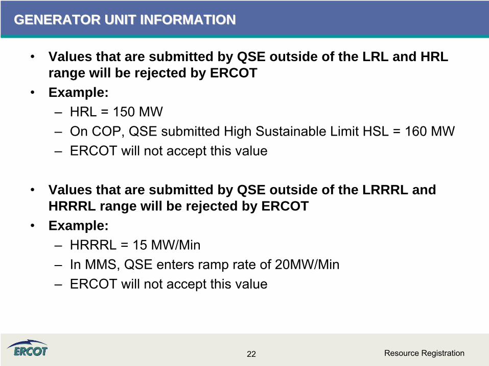
GENERATOR UNIT INFORMATIONGENERATOR UNIT INFORMATION
•
Values that are submitted by QSE outside of the LRL and HRL range will be rejected by ERCOT
•
Example:–
HRL = 150 MW–
On COP, QSE submitted High Sustainable Limit HSL = 160 MW–
ERCOT will not accept this value
•
Values that are submitted by QSE outside of the LRRRL and HRRRL range will be rejected by ERCOT
•
Example:–
HRRRL = 15 MW/Min–
In MMS, QSE enters ramp rate of 20MW/Min–
ERCOT will not accept this value
Resource Registration23
GENERATOR UNIT INFORMATIONGENERATOR UNIT INFORMATION
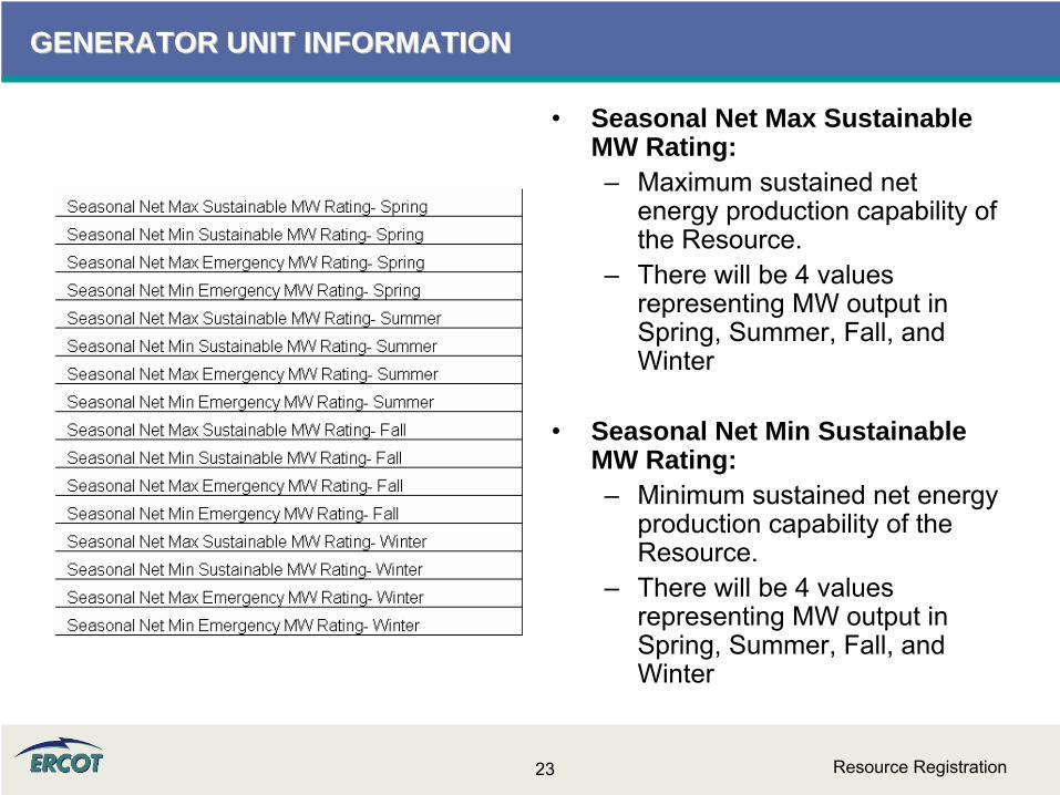
•
Seasonal Net Max Sustainable MW Rating:–
Maximum sustained net energy production capability of the Resource.
–
There will be 4 values representing MW output in Spring, Summer, Fall, and Winter
•
Seasonal Net Min Sustainable MW Rating:–
Minimum sustained net energy production capability of the Resource.
–
There will be 4 values representing MW output in Spring, Summer, Fall, and Winter

Resource Registration24
GENERATOR UNIT INFORMATIONGENERATOR UNIT INFORMATION
•
Seasonal Net Max Emergency MW Rating:–
Limit established by the QSE describing the maximum temporary unsustainable energy production capability of the Resource.
–
This limit must be achievable for a time stated by the QSE, but not less than 30 minutes.
–
There will be 4 values representing MW output in Spring, Summer, Fall, and Winter
•
Seasonal Net Min Emergency MW Rating:–
Limit established by the QSE describing the minimum temporary unsustainable energy production capability of the Resource.
–
This limit must be achievable for a time stated by the QSE, but not less than 30 minutes.
–
There will be 4 values representing MW output in Spring, Summer, Fall, and Winter
Resource Registration25
GENERATOR UNIT INFORMATIONGENERATOR UNIT INFORMATION
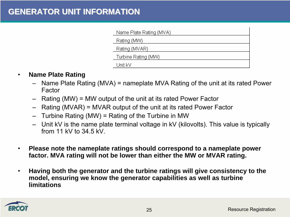
•
Name Plate Rating–
Name Plate Rating (MVA) = nameplate MVA Rating of the unit at its rated Power Factor
–
Rating (MW) = MW output of the unit at its rated Power Factor–
Rating (MVAR) = MVAR output of the unit at its rated Power Factor–
Turbine Rating (MW) = Rating of the Turbine in MW–
Unit kV is the name plate terminal voltage in kV (kilovolts). This value is typically from 11 kV to 34.5 kV.
•
Please note the nameplate ratings should correspond to a nameplate power factor. MVA rating will not be lower than either the MW or MVAR rating.
•
Having both the generator and the turbine ratings will give consistency to the model, ensuring we know the generator capabilities as well as turbine limitations

Resource Registration26
GENERATOR UNIT INFORMATION GENERATOR UNIT INFORMATION –– FAQ FAQ
•
What are the seasonal sustainable and emergency ratings?–
PMAX–
Net = Generation less Auxiliary–
Also the data is used 4.4.9.4.1 Mitigated Offer Cap in calculating the capacity factor of the resource.
•
How are these used by Nodal systems?–
This information is used in planning studies. In addition, the data is used 4.4.9.4.1 Mitigated Offer Cap in calculating the capacity factor of the resource.
•
What if the Emergency MW and Sustainable MW ratings are the same?–
These values can be the same. If this is the case, fill in the same values for corresponding fields.

Resource Registration27
GENERATOR UNIT INFORMATION GENERATOR UNIT INFORMATION –– FAQFAQ
•
What are the High/Low Reasonability Limits?–
An "Out-of-Bounds" value chosen by RE and used by ERCOT to alarm/reject data exceeding the value per Nodal Protocol 3.7.1. This value is used to validate data submitted to ERCOT (Alarms, ICCP, COP).
–
Any submittals such as a High Sustainable Limit in the COP that exceed the High Reasonability Limit will be rejected by ERCOT systems.
REACTIVE CAPABILITY CURVESREACTIVE CAPABILITY CURVES

Resource Registration29
REACTIVE CAPABILITY CURVESREACTIVE CAPABILITY CURVES
•
Reactive Capability is the ability of a Generator unit to supply/absorb Reactive Power (MVAR) to the grid continuously for a given MW operating value without damaging the unit.
•
Reactive Power is required to control voltages under normal and emergency situations in order to prevent voltage collapse of the grid.
•
RE shall conduct reactive capacity qualification tests to verify maximum leading and lagging reactive capability of all Generation Resources required to provide VSS.
•
Reactive Capability tests are performed on initial qualification and at a minimum of once every two years as required by ERCOT.

Resource Registration30
REACTIVE CAPABILITY CURVESREACTIVE CAPABILITY CURVES
•
Figure on the left shows a typical Reactive Capability Curve or D-
Curve of a Generator unit
•
X-axis is MW and Y-axis is MVAR
•
Values above the x-axis (positive VARs) are “LAGGING”
MVARs
•
Values below the x-axis (negative VARs) are “LEADING”
MVARs
•
Straight lines correspond to different power factor (PF) values
•
RE will supply D-Curves for their Generator units to ERCOT

Resource Registration31
REACTIVE CAPABILITY CURVESREACTIVE CAPABILITY CURVES
•
The Reactive Capability Curve, also known as the D-curve, represents the operating limits of the generator
•
ERCOT is asking for nine points of information in order to build the curve
•
Use positive (lagging MVAR) and negative numbers (leading MVAR) as shown to the right
•
If Hydrogen cooled, indicate pressure of Hydrogen in psi
•
Supply 5 increasing MW values of Operating Real Power
–
MW1 (lowest operating), MW2, MW3, MW4, & MW5 (unity)
Resource Registration32
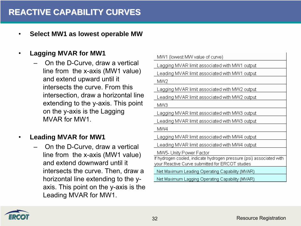
REACTIVE CAPABILITY CURVESREACTIVE CAPABILITY CURVES
•
Select MW1 as lowest operable MW
•
Lagging MVAR for MW1–
On the D-Curve, draw a vertical line from the x-axis (MW1 value) and extend upward until it intersects the curve. From this intersection, draw a horizontal line extending to the y-axis. This point on the y-axis is the Lagging MVAR for MW1.
•
Leading MVAR for MW1–
On the D-Curve, draw a vertical line from the x-axis (MW1 value) and extend downward until it intersects the curve. Then, draw a horizontal line extending to the y-
axis. This point on the y-axis is the Leading MVAR for MW1.
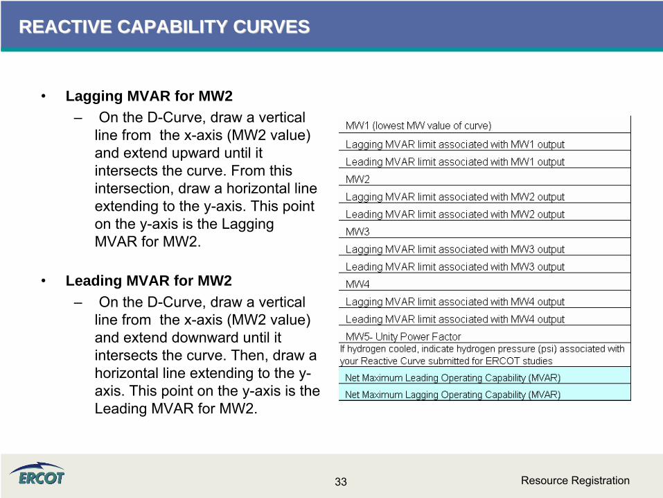
Resource Registration33
REACTIVE CAPABILITY CURVESREACTIVE CAPABILITY CURVES
•
Lagging MVAR for MW2–
On the D-Curve, draw a vertical line from the x-axis (MW2 value) and extend upward until it intersects the curve. From this intersection, draw a horizontal line extending to the y-axis. This point on the y-axis is the Lagging MVAR for MW2.
•
Leading MVAR for MW2–
On the D-Curve, draw a vertical line from the x-axis (MW2 value) and extend downward until it intersects the curve. Then, draw a horizontal line extending to the y-
axis. This point on the y-axis is the Leading MVAR for MW2.

Resource Registration34
REACTIVE CAPABILITY CURVESREACTIVE CAPABILITY CURVES
•
Lagging MVAR for MW3–
On the D-Curve, draw a vertical line from the x-axis (MW3 value) and extend upward until it intersects the curve. From this intersection, draw a horizontal line extending to the y-axis. This point on the y-axis is the Lagging MVAR for MW3.
•
Leading MVAR for MW3–
On the D-Curve, draw a vertical line from the x-axis (MW3 value) and extend downward until it intersects the curve. Then, draw a horizontal line extending to the y-
axis. This point on the y-axis is the Leading MVAR for MW3.

Resource Registration35
REACTIVE CAPABILITY CURVESREACTIVE CAPABILITY CURVES
•
Lagging MVAR for MW4–
On the D-Curve, draw a vertical line from the x-axis (MW4 value) and extend upward until it intersects the curve. From this intersection, draw a horizontal line extending to the y-axis. This point on the y-axis is the Lagging MVAR for MW4.
•
Leading MVAR for MW4–
On the D-Curve, draw a vertical line from the x-axis (MW4 value) and extend downward until it intersects the curve. Then, draw a horizontal line extending to the y-
axis. This point on the y-axis is the Leading MVAR for MW4.

Resource Registration36
REACTIVE CAPABILITY CURVESREACTIVE CAPABILITY CURVES
•
MW5 – Unity Power Factor–
Maximum value of Real Power MW at 1.0 PF. For MW5, Reactive Power (both lagging & leading) is zero (crosses the x-axis).
•
Net Maximum Leading Operating Capability (MVAR)–
Maximum Leading Reactive Power output of the unit independent of Real Power output
•
Net Maximum Lagging Operating Capability (MVAR)–
Maximum Lagging Reactive Power output of the unit independent of Real Power output

Resource Registration37
REACTIVE CAPABILITY CURVESREACTIVE CAPABILITY CURVES
Lagging
Leading
•
Sample input data table
•
Sample D-Curve used to create the data used in the table on left

Resource Registration38
REACTIVE CAPABILITY CURVES REACTIVE CAPABILITY CURVES –– FAQ FAQ
•
Does ERCOT want the Manufacturer’s power curve added as a separate tab to this document?–
Please include Capability Curve as a separate document.
•
For "Net Maximum Leading Operating Capability (MVAR)" and "Net Maximum Lagging Operating Capability (MVAR)", what is "Net"?–
Net is Generation less Auxiliary load.

Resource Registration39
REACTIVE CAPABILITY CURVE REACTIVE CAPABILITY CURVE –– HOW TOHOW TO
MW
5
MW1 should be at lowest operating condition.
MW5 should be where the curve crosses the x-
axis (unity pf)

Resource Registration40
REACTIVE CAPABILITY CURVE REACTIVE CAPABILITY CURVE –– HOW TOHOW TO
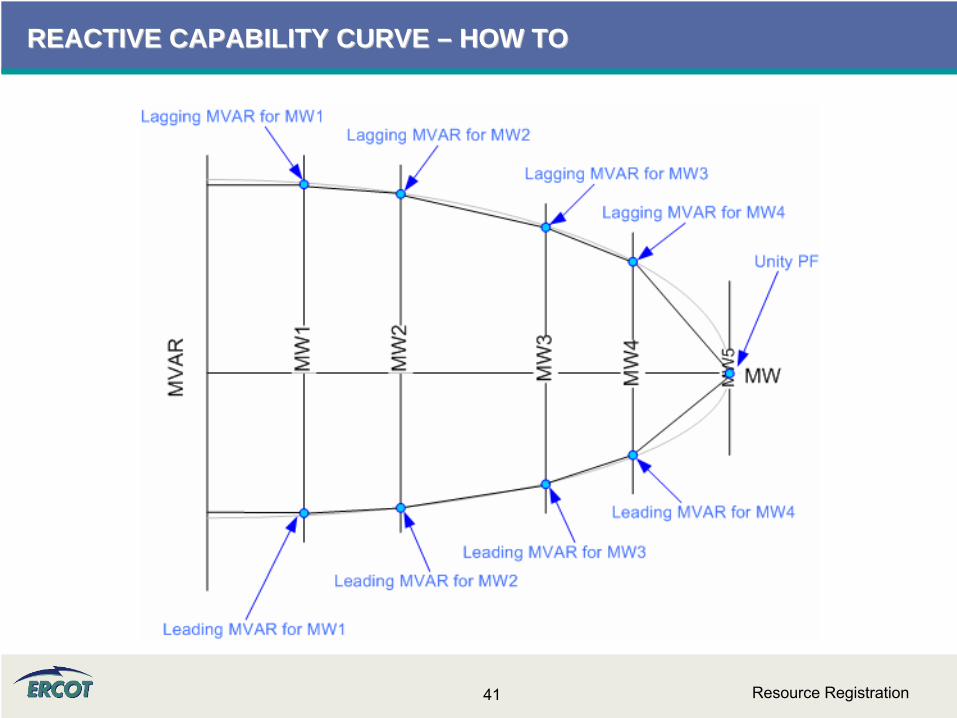
Resource Registration41
REACTIVE CAPABILITY CURVE REACTIVE CAPABILITY CURVE –– HOW TOHOW TO
OPERATIONAL RESOURCE PARAMETERSOPERATIONAL RESOURCE PARAMETERS
Resource Registration43
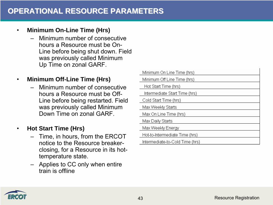
OPERATIONAL RESOURCE PARAMETERSOPERATIONAL RESOURCE PARAMETERS
•
Minimum On-Line Time (Hrs)–
Minimum number of consecutive hours a Resource must be On-
Line before being shut down. Field was previously called Minimum Up Time on zonal GARF.
•
Minimum Off-Line Time (Hrs)–
Minimum number of consecutive hours a Resource must be Off-
Line before being restarted. Field was previously called Minimum Down Time on zonal GARF.
•
Hot Start Time (Hrs)–
Time, in hours, from the ERCOT notice to the Resource breaker-
closing, for a Resource in its hot-
temperature state.
–
Applies to CC only when entire train is offline

Resource Registration44
OPERATIONAL RESOURCE PARAMETERSOPERATIONAL RESOURCE PARAMETERS
•
Intermediate Start Time (Hrs)–
Time interval, in hours, from the ERCOT notice to the Resource breaker-closing, for a Resource in its intermediate temperature state.
–
Applies to CC only when entire train is offline
•
Cold Start Time (Hrs)–
Time interval, in hours, from the ERCOT notice to the Resource breaker-closing, for a Resource in its cold-temperature state.
–
Applies to CC only when entire train is offline
•
Max Weekly Starts–
The maximum number of times a Resource can be started in seven consecutive days under normal operating conditions.

Resource Registration45
OPERATIONAL RESOURCE PARAMETERSOPERATIONAL RESOURCE PARAMETERS
•
Max On Line Time (Hrs)–
Maximum number of consecutive hours a Resource can run before it needs to be shut down.
•
Max Daily Starts–
Maximum number of times a Resource can be started in a 24 hour period under normal operating conditions.
•
Max Weekly Energy–
Maximum amount of energy, in MWh, a Resource can produce in seven consecutive days.

Resource Registration46
OPERATIONAL RESOURCE PARAMETERSOPERATIONAL RESOURCE PARAMETERS

Resource Registration47
OPERATIONAL RESOURCE PARAMETERSOPERATIONAL RESOURCE PARAMETERS
•
Ramp Rate Curve data will be entered for both Normal and Emergency Operations–
Ramp rates are initially submitted in the RARF
–
QSEs will be able to update the ramp rates in Market Management System (MMS)
•
Ramp rates will be in the up and down directions
•
Ramp rate curves are step functions
•
Ten segments/steps to RR curve NEW!!**
** This document still reflects 5 segments.

Resource Registration48
OPERATIONAL RESOURCE PARAMETERSOPERATIONAL RESOURCE PARAMETERS
•
All ramp rate values, including downward rates, should be entered in the RARF as positive values
•
Ramp Rates and curves are critical and must be provided for every unit
•
In the case of Combined-Cycle facilities, Ramp Rates curves are needed for every configuration
•
The values in the RARF are used to build the Ramp Rate step curves
Resource Registration49
OPERATIONAL RESOURCE PARAMETERSOPERATIONAL RESOURCE PARAMETERS
•
Ramp Rate Curves are not tools to restrain the operating range of the unit or configuration
•
Ramp Rate Curves are extended down to zero and up to infinity.
–
Realistically, the curves are limited to LRL and HRL.
–
Further operating restrictions are done as part of the COP and telemetry
•
Ramp Rates should not be zero or negative
•
For ranges where the resource has to be manually ramped; the up and down ramp rate should be a MW rate at which, if requested, the resource can be manually ramped to within a 5 minute period
Resource Registration50
OPERATIONAL RESOURCE PARAMETERSOPERATIONAL RESOURCE PARAMETERS
•
Decimal values are acceptable–
At this time, EDS testing is rounding these values. This issue is being resolved
•
If there is only one ramp rate, then only one MW value needs to be filled in
•
If not all five MW values are used, use only MW1 through MWx as needed–
For example, if there are three rates, then use MW1, MW2, and MW3.
Resource Registration51
OPERATIONAL RESOURCE PARAMETERSOPERATIONAL RESOURCE PARAMETERS
•
The table below further defines the Ramp Rates. It also may help
to sketch your curves to ensure the submitted
data is accurate.
MW1 (MW1/Low to MW5/High end of curve) Covers all MW values between LRL and MW2 Upward RampRate1 (MW/minute) The upward rate of change in MW/minute for any MW value between LRL to MW2 Downward RampRate1 (MW/minute) positive number The downward rate of change in MW/minute for any MW value between LRL and MW2 MW2 Covers all MW values between MW2 and MW3 Upward RampRate2 (MW/minute) The upward rate of change in MW/minute for any MW value between MW2 and MW3 Downward RampRate2 (MW/minute) The downward rate of change in MW/minute for any MW value between MW2 and MW3 MW3 Covers all MW values between MW3 and MW4 Upward RampRate3 (MW/minute) The upward rate of change in MW/minute for any MW value between MW3 and MW4 Downward RampRate3 (MW/minute) The downward rate of change in MW/minute for any MW value between MW3 and MW4 MW4 Covers all MW values between MW4 and MW5 Upward RampRate4 (MW/minute) The upward rate of change in MW/minute for any MW value between MW4 and MW5 Downward RampRate4 (MW/minute) The downward rate of change in MW/minute for any MW value between MW4 and MW5 MW5 Covers all MW values between MW5 and HRL Upward RampRate5 (MW/minute) The upward rate of change in MW/minute for any MW value between MW5 and HRL Downward RampRate5 (MW/minute) The downward rate of change in MW/minute for any MW value between MW5 and HRL
Ramp Rate Curve
Ramp Rate Curve: The rate of change in MW per minute of a Resource, specified by the QSE to ERCOT by up to 10 segrments, each segment represents a single MW per minute value (across the capacity of the Resource) that describe the available rate of change in output for the given range (between HRL and LRL) of output of a Resource.
Resource Registration52
OPERATIONAL RESOURCE PARAMETERSOPERATIONAL RESOURCE PARAMETERS
•
SAMPLE RAMP RATE TABLE AND RAMP RATE CURVE
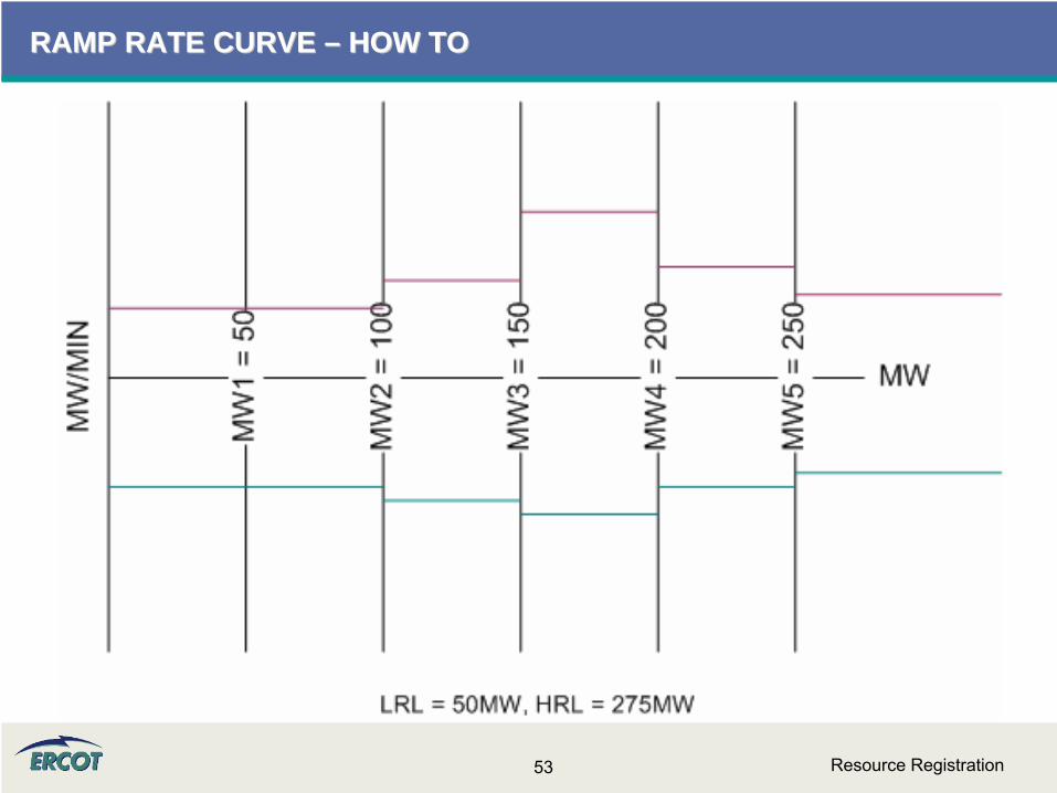
Resource Registration53
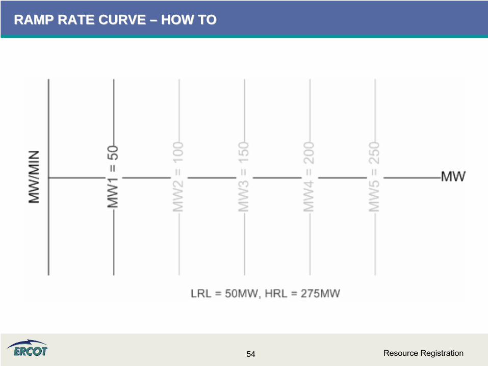
RAMP RATE CURVE RAMP RATE CURVE –– HOW TOHOW TO
Resource Registration54
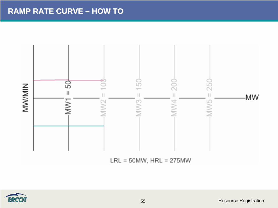
RAMP RATE CURVE RAMP RATE CURVE –– HOW TOHOW TO
Resource Registration55
RAMP RATE CURVE RAMP RATE CURVE –– HOW TOHOW TO

Resource Registration56
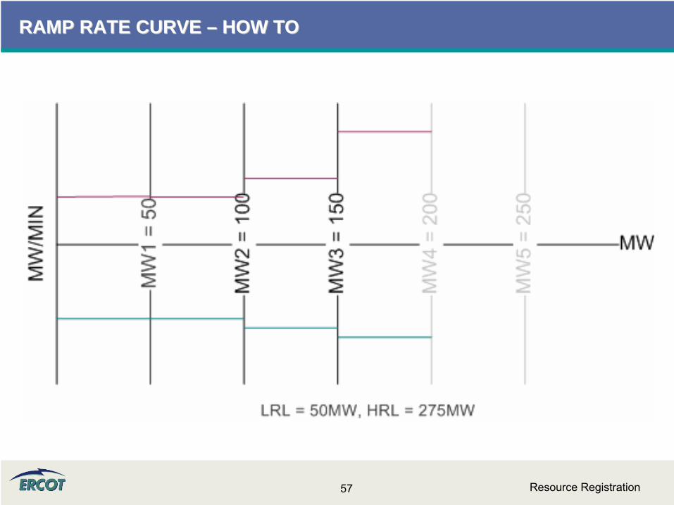
RAMP RATE CURVE RAMP RATE CURVE –– HOW TOHOW TO
Resource Registration57
RAMP RATE CURVE RAMP RATE CURVE –– HOW TOHOW TO

Resource Registration58
RAMP RATE CURVE RAMP RATE CURVE –– HOW TOHOW TO
Resource Registration59
RAMP RATE CURVE RAMP RATE CURVE –– HOW TOHOW TO
Resource Registration60
RAMP RATE CURVE RAMP RATE CURVE –– HOW TOHOW TO
Resource Registration61
OPERATIONAL RESOURCE PARAMETERS OPERATIONAL RESOURCE PARAMETERS –– FAQFAQ
•
What if there are multiple breakers?–Provide time from initiating start to the last breaker to close in achieving the registered configuration.
•
If I enter zero as minimum online time, will I get startup costs if I am pulled offline before I close the breaker?
–5.6.2 RUC Startup Cost Eligibility(d)
The generation breakers must have been closed, as indicated by a telemetered
Resource status of On-Line, for at least one minute during the RUC commitment period or after the determined five-minute open breaker, as indicated by a telemetered
Resource status of Off-Line, in the six hours preceding the first RUC-Committed Hour.

Resource Registration62
OPERATIONAL RESOURCE PARAMETERS OPERATIONAL RESOURCE PARAMETERS –– FAQFAQ
•
Can you input the min interruption and restoration times in minutes or hours? If hours, can you show a fraction of say .25 for 15 min? –
RUC Commitment is hourly, so the values should be in whole hours.
•
For the Max Weekly Starts, can you show a fraction? i.e. if once every 2 weeks is desired, can you insert a 0.5?–
This value, along with the others in this section of the RARF, should only be in whole numbers over a seven day (1-week evaluation period). A fraction or a number representing any period other than the seven day window is not appropriate.
Resource Registration63
OPERATIONAL RESOURCE PARAMETERS OPERATIONAL RESOURCE PARAMETERS –– FAQFAQ
•
What is the definition of ranges for “hot”, “intermediate”, and “cold” starts and cool-downs. And where in those temperature ranges should the turbine starts and ends be?–
Hot conditions vary unit by unit, so this question is difficult to answer. Also, this information can be updated by the QSE through the MMS if found to be inappropriate.
–
Some general thoughts, but not requirements, are that conditions
for a steam unit can be hot through an overnight shutdown and conditions often reflect a unit as cold after a two or three day
shutdown. Intermediate would then be a Resource that has recently been online and for which neither hot nor cold conditions are applicable.
Resource Registration64
OPERATIONAL RESOURCE PARAMETERS OPERATIONAL RESOURCE PARAMETERS –– FAQFAQ
•
For Ramp Rate Curves, the ramp rate varies in different operational scenarios, such as winter, summer etc. What does "Normal" mean?–
ERCOT desires the ramp rate curve from the Low Sustainable Limit (LSL) to the High Sustainable Limit (HSL) and can be entered in 5-pairs at different MW levels.
–
If there are significant changes in operational conditions (derating, unplanned outages, seasonal configuration changes) the ramp rate curves can be updated with the QSE providing a reason code -
but this should be only a few times per year.

Resource Registration65
OPERATIONAL RESOURCE PARAMETERS OPERATIONAL RESOURCE PARAMETERS –– FAQFAQ
•
Does ERCOT want per day or per year data for the "Minimum On/Off Line Time (hrs)" and "Max On Line Time (hrs)"? –
Minimum online and offline time is defined in the Protocols 3.7.1.1(1). This information should be in whole hours. Min Online time represents the minimum number of consecutive hours the Resource must be On-Line before being shut down. Min Offline time is the minimum number of consecutive hours the Resource must be Off-Line before being restarted.
–
When filling out these values for base load units, please make appropriate assumptions.
•
For example, when a unit comes online and needs to be taken offline, provide the minimum time online before it could be taken offline. Then assume it is offline. Provide minimum time it would have to remain offline before it could be brought back on.
–
For Load Resources, the information is required per Nodal Protocols and detailed in 3.7.1.2.
Resource Registration66
OPERATIONAL RESOURCE PARAMETERS OPERATIONAL RESOURCE PARAMETERS –– FAQFAQ
•
What data does ERCOT look for in "Max Weekly Energy"?–
Max Weekly Energy would be the maximum energy a unit can produce during a seven day window, in MWh and would be considered as a constraint by the RUC program in the selection of resources. If you are not aware of special production limits,
you may not have any. An example of a limitation could be production limited in order to meet for environmental requirements.
•
For ‘Maximum Weekly Energy’ on the RARF form, do you want this based on a seasonal rating? If so, which season?–
This should not be seasonal –
but it is a field that the QSE can update in the MMS with supporting information.

Resource Registration67
OPERATIONAL RESOURCE PARAMETERS OPERATIONAL RESOURCE PARAMETERS –– FAQFAQ
•
What is maximum Weekly Energy, specifically for a base load unit?–
For a base load unit, enter the energy for a week (24x7). This is required per Nodal Protocols 3.7.1. This value will be updated by QSE through the MMS.
•
For base load units that we do not intend for frequent starts, how is that filled in on the RARF for the “maximum daily and weekly starts”?–
The maximum starts are to be used as a constraint in RUC for an evaluation in the case that a unit can be brought online by RUC. If the unit were to be (although rare) offline and available to ERCOT for procurement by RUC, this value on the RARF would be the proper constraint to reflect the maximum number of starts for the resource. So the Resource should provide a whole
number value.

COMBINEDCOMBINED--CYCLECYCLE
Resource Registration69
COMBINEDCOMBINED--CYCLECYCLE
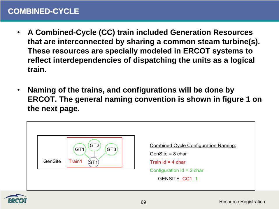
•
A Combined-Cycle (CC) train included Generation Resources that are interconnected by sharing a common steam turbine(s). These resources are specially modeled in ERCOT systems to reflect interdependencies of dispatching the units as a logical train.
•
Naming of the trains, and configurations will be done by ERCOT. The general naming convention is shown in figure 1 on the next page.
GT1 GT3GT2
ST1Train1GenSite
Combined Cycle Configuration Naming:
GenSite = 8 char
Train id = 4 char
Configuration id = 2 char
GENSITE_CC1_1
Resource Registration70
COMBINEDCOMBINED--CYCLECYCLE
•
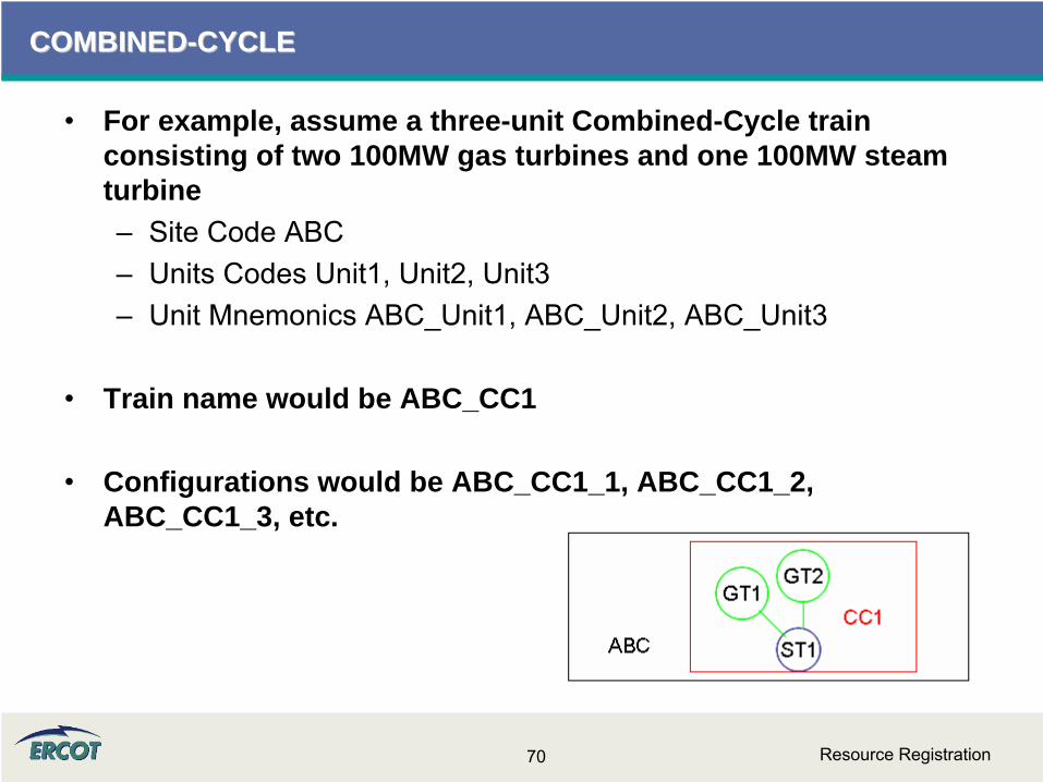
For example, assume a three-unit Combined-Cycle train consisting of two 100MW gas turbines and one 100MW steam turbine–
Site Code ABC–
Units Codes Unit1, Unit2, Unit3–
Unit Mnemonics ABC_Unit1, ABC_Unit2, ABC_Unit3
•
Train name would be ABC_CC1
•
Configurations would be ABC_CC1_1, ABC_CC1_2, ABC_CC1_3, etc.
Resource Registration71
COMBINEDCOMBINED--CYCLECYCLE
•
There is no protocol reference stating a CC must register as a CC or otherwise.
•
The definition in Protocol Section 2 defines a Combined-Cycle Configuration to be:
“Any combination in which a combined-cycle power block can be operated as a separate Resource. Each possible configuration operated as a separate Resource has a distinct set of operating parameters, physical constraints, and Energy Offer Curve.”
•
The CC owner has the option of registering the CC site as combined-cycle or as separate units. However, registering the CC as a train will improve modeling and dispatch.
•
A combustion turbine and steam turbine on a single shaft are considered to be a single generation unit, not a combined-cycle train.
Resource Registration72
COMBINEDCOMBINED--CYCLECYCLE
•
In the Nodal system, combined-cycle resources will not be registered in ERCOT systems as split generation (joint ownership).
•
Combined-Cycle (CC) resources can submit different configurations on the RARF. The number of configurations registered is limited only to operationally unique configurations.
•
There is a limit to the number of CC configurations in one train that can be available operationally (COP). This limit is set by the number of units in the train. A CC train with 3 units would be able to have 3 configurations “available”.
•
Each unit of a CC train needs to have registration parameters entered individually as well.

Resource Registration73
COMBINEDCOMBINED--CYCLECYCLE
•
Name and mnemonic assigned by ERCOT
•
Fuel transportation type and resource category apply to train, not unit level
•
Augmentation is not separate unit or configuration, but included within limits of configurations–
Indicate what augmentation is in service

Resource Registration74
COMBINEDCOMBINED--CYCLECYCLE
•
Unit information data required for units AND configurations
•
Resource parameter data required for configurations, but not for CC units.

Resource Registration75
COMBINEDCOMBINED--CYCLECYCLE
•
Combined-Cycle augmentations should not be a separate configuration. –
Power augmentations should be accounted for in the limits set for any configuration they could be used but is not a separate configuration.
•
Do NOT register every configuration. –
Register operationally unique configurations. For every CT that is reasonable, enter “X”
for the primary CT and enter “A”
for every alternate. At this time, an instruction would identify the
configuration, and the selection of the unit (“X”
or any submitted “A”) is up to the entity.
•
Configurations are entered as increasing MW and unit order.–
The transition matrix will fall out as “increasing”
above the diagonal, and “decreasing”
below the diagonal. Also, it will help to keep start-up costs aligned.
Resource Registration76
COMBINEDCOMBINED--CYCLECYCLE
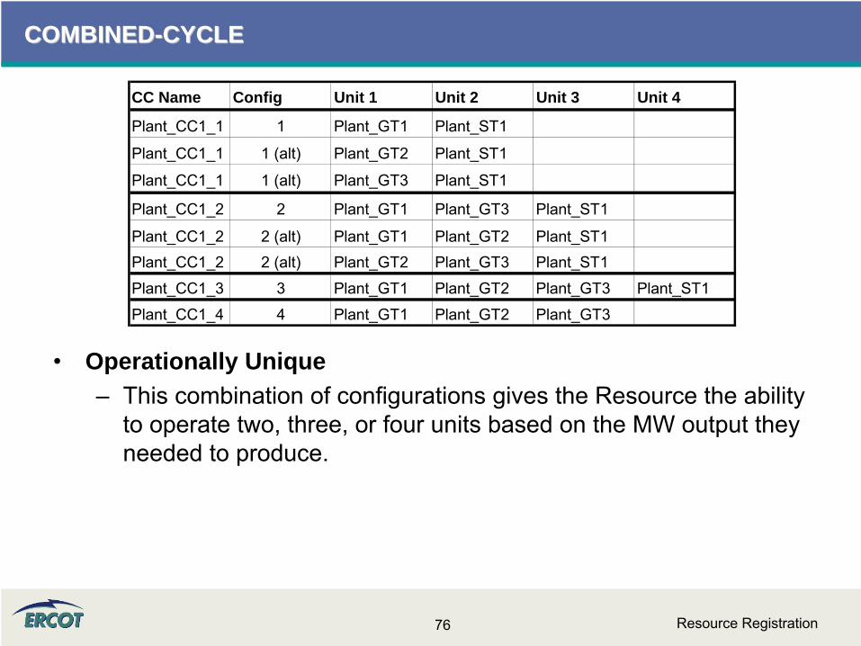
CC Name Config Unit 1 Unit 2 Unit 3 Unit 4
Plant_CC1_1 1 Plant_GT1 Plant_ST1
Plant_CC1_1 1 (alt) Plant_GT2 Plant_ST1
Plant_CC1_1 1 (alt) Plant_GT3 Plant_ST1
Plant_CC1_2 2 Plant_GT1 Plant_GT3 Plant_ST1
Plant_CC1_2 2 (alt) Plant_GT1 Plant_GT2 Plant_ST1Plant_CC1_2 2 (alt) Plant_GT2 Plant_GT3 Plant_ST1
Plant_CC1_3 3 Plant_GT1 Plant_GT2 Plant_GT3 Plant_ST1
Plant_CC1_4 4 Plant_GT1 Plant_GT2 Plant_GT3
•
Operationally Unique–
This combination of configurations gives the Resource the ability to operate two, three, or four units based on the MW output they
needed to produce.

Resource Registration77
COMBINEDCOMBINED--CYCLECYCLE
•
A long Minimum Online Time can have negative effects on RUC and may limit the movement of the train. At this time, there is no way to slow the steamer only.
•
Combined-Cycle in a split-bus situations:–
CC on two voltage levels inside ERCOT would be registered and treated as separate units and not a single train.
–
GT and ST on the same grid could still be treated as combined-
cycle, and an individual GT on a different grid, for example, would be treated as an independent, traditional generator. These
circumstances may lead to a 0-on-1 configuration that can be registered.
–
In a split-bus situations with only the steamer as the odd unit connection, these unit will be treated as simple cycle generators and not a Combined-Cycle Resource.
Resource Registration78
COMBINEDCOMBINED--CYCLECYCLE
•
If a resource is currently registered with a Resource Category of Combined-Cycle, then the resource should be registered as combined-cycle on the RARF.
•
Conversely, if the unit registers as a combined-cycle, then the Resource Category needs to be a Combined-Cycle
•
ERCOT will appoint a particular naming convention for Combined-Cycle units of Private networks. RARF is pre- populated with the mnemonics for currently registered units.

Resource Registration79
COMBINEDCOMBINED--CYCLECYCLE
•
Figure below shows the alternate designation “A” has been used to indicate that specific units can be substituted for others. An “X” symbol indicates unit(s) being used in the CC Train.
•
However, configurations 1, 2, and 3 all result in the same configuration since the alternate unit can substitute for any other GT units. These configurations are not “operationally unique.”
•
The ST can never be an “A” as there is no other unit of the same type on this train. For clarity purposes, this example does not use actual RARF unit types.
CC Unit Type Configuration 1 Configuration 2 Configuration 3 Configuration 4 Configuration 5Plant_GT1 GT X X A XPlant_GT2 GT X A X XPlant_GT3 GT A X X XPlant_ST1 ST X X X X
Unit 5
Resource Registration80
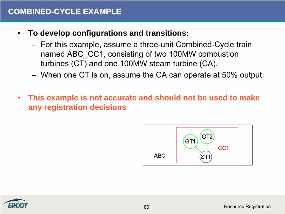
COMBINEDCOMBINED--CYCLE EXAMPLECYCLE EXAMPLE
•
To develop configurations and transitions: –
For this example, assume a three-unit Combined-Cycle train named ABC_CC1, consisting of two 100MW combustion turbines (CT) and one 100MW steam turbine (CA).
–
When one CT is on, assume the CA can operate at 50% output.
•
This example is not accurate and should not be used to make any registration decisions
Resource Registration81
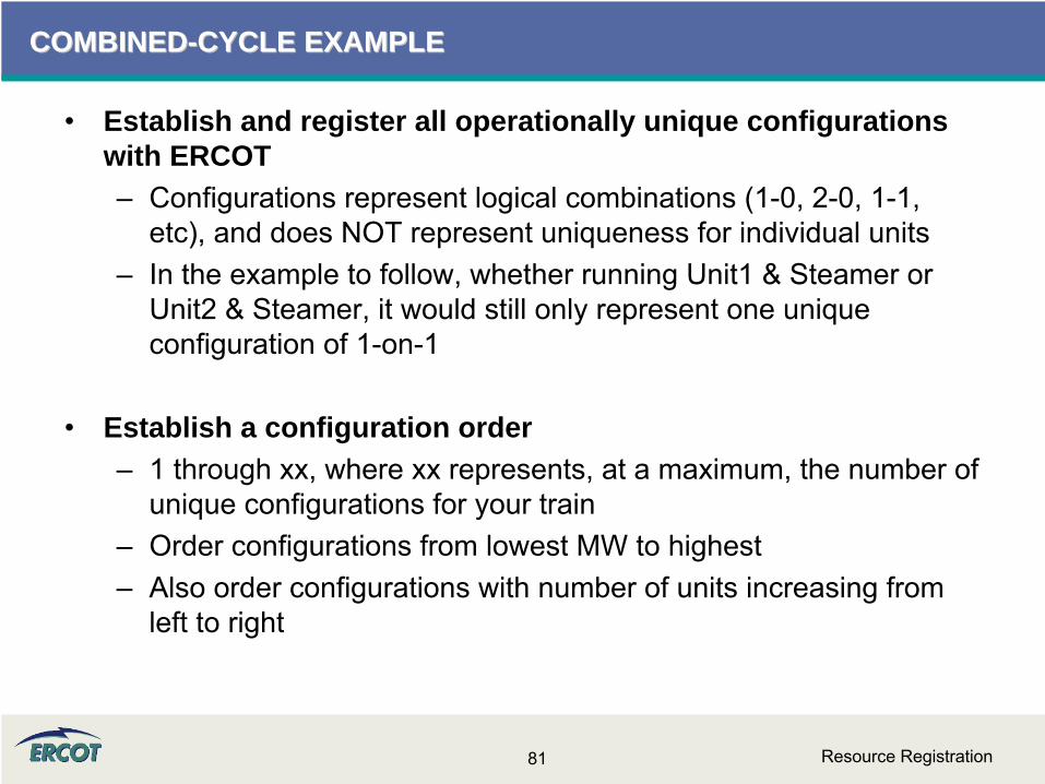
COMBINEDCOMBINED--CYCLE EXAMPLECYCLE EXAMPLE
•
Establish and register all operationally unique configurations with ERCOT–
Configurations represent logical combinations (1-0, 2-0, 1-1, etc), and does NOT represent uniqueness for individual units
–
In the example to follow, whether running Unit1 & Steamer or Unit2 & Steamer, it would still only represent one unique configuration of 1-on-1
•
Establish a configuration order–
1 through xx, where xx represents, at a maximum, the number of unique configurations for your train
–
Order configurations from lowest MW to highest–
Also order configurations with number of units increasing from left to right

Resource Registration82
COMBINEDCOMBINED--CYCLE EXAMPLECYCLE EXAMPLE
•
CC1 can operate in four unique configurations – 1x0, 2x0, 1x1, and 2x1.
•
Each configuration has a different MW output.
•
These configurations and the output have been identified in the table to the right.
•
Applying the configuration order requirement, the yellow cells identify the order that they should be entered into the RARF
MW 1x0 2x0 1x1 2x1Unit 1 CT 100 x x x xUnit 2 CT 100 a x a xUnit 3 CA 100 x x
300 100 200 150 3001 3 2 4
CC1
Resource Registration83
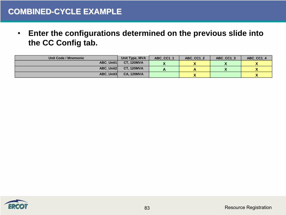
COMBINEDCOMBINED--CYCLE EXAMPLECYCLE EXAMPLE
•
Enter the configurations determined on the previous slide into the CC Config tab.
Unit Code / Mnemonic Unit Type, MVA ABC_CC1_1 ABC_CC1_2 ABC_CC1_3 ABC_CC1_4ABC_Unit1 CT, 120MVA X X X XABC_Unit2 CT, 120MVA A A X XABC_Unit3 CA, 120MVA X X

Resource Registration84
COMBINEDCOMBINED--CYCLE EXAMPLECYCLE EXAMPLE
•
Enter resource parameter information for the configurations. ABC_CC1_1 ABC_CC1_2 ABC_CC1_3 ABC_CC1_4
95 140 190 28530 45 60 755 2 5 22 1 2 1
95 140 190 28530 45 60 75100 150 200 30025 40 55 7095 140 190 285
30 45 60 75100 150 200 30025 40 55 7095 140 190 28530 45 60 75100 150 200 30025 40 55 7095 140 190 28530 45 60 75100 150 200 30025 40 55 70
1 2 1 21 1 1 11 2 1 22 4 2 43 6 3 6
10 5 10 52000 2000 2000 2000
2 1 2 116800
2 2 2 23 3 3 3
30 45 60 755 2 5 22 1 2 1
95 80 95 1005 3 6 32 3 3 3
110 110 1804 5 43 2 3
140 2851 15 5
Low Reasonability Limit (Min Net MW level) High Reasonability Limit (Max Net MW level)
Seasonal Net Min Sustainable MW Rating- Spring Seasonal Net Max Sustainable MW Rating- Spring Low Reasonability Ramp Rate Limit (Min ramp MW/min) High Reasonability Ramp Rate Limit (Max ramp MW/min)
Seasonal Net Min Sustainable MW Rating- Summer
Seasonal Net Max Sustainable MW Rating- Summer Seasonal Net Min Emergency MW Rating- Spring Seasonal Net Max Emergency MW Rating- Spring
Seasonal Net Min Emergency MW Rating- Winter Seasonal Net Max Emergency MW Rating- Winter
Upward RampRate5 (MW/minute) Downward RampRate5 (MW/minute)
MW4 Upward RampRate4 (MW/minute) Downward RampRate4 (MW/minute) MW5
Downward RampRate2 (MW/minute) MW3 Upward RampRate3 (MW/minute) Downward RampRate3 (MW/minute)
Upward RampRate1 (MW/minute) Downward RampRate1 (MW/minute) positive number MW2 Upward RampRate2 (MW/minute)
Field Description
Minimum On Line Time (hrs) Minimum Off Line Time (hrs) Hot Start Time (hrs)
Seasonal Net Min Emergency MW Rating- Fall Seasonal Net Max Emergency MW Rating- Fall Seasonal Net Min Sustainable MW Rating- Fall Seasonal Net Max Sustainable MW Rating- Fall Seasonal Net Min Emergency MW Rating- Summer Seasonal Net Max Emergency MW Rating- Summer
Intermediate Start Time (hrs) Cold Start Time (hrs) Max Weekly Starts Max On Line Time (hrs)
Normal Ramp Rate Curve MW1 (MW1/Low to MW5/High end of curve)
Seasonal Net Min Sustainable MW Rating- Winter Seasonal Net Max Sustainable MW Rating- Winter
Max Daily Starts Max Weekly Energy Hot-to-Intermediate Time (hrs) Intermediate-to-Cold Time (hrs)

Resource Registration85
COMBINEDCOMBINED--CYCLE EXAMPLECYCLE EXAMPLE
•
Construct a state diagram, where each configuration is a “state” represented by a circle.
•
Draw arrows from each configuration to any other that can be reached within the minimum online time.
•
The state diagram should be laid out from left to right, where OFFLINE is furthest to the left, and the highest configuration is represented furthest to the right.
•
Draw arrows between states/configurations to indicate where the train could operate next.
•
If the configurations were assigned correctly–
Arrows to the right should add a unit and increase MW. –
Arrows to the left should indicate decreasing MW and units. •
This diagram will be used to build an accurate transition matrix for the Nodal systems.
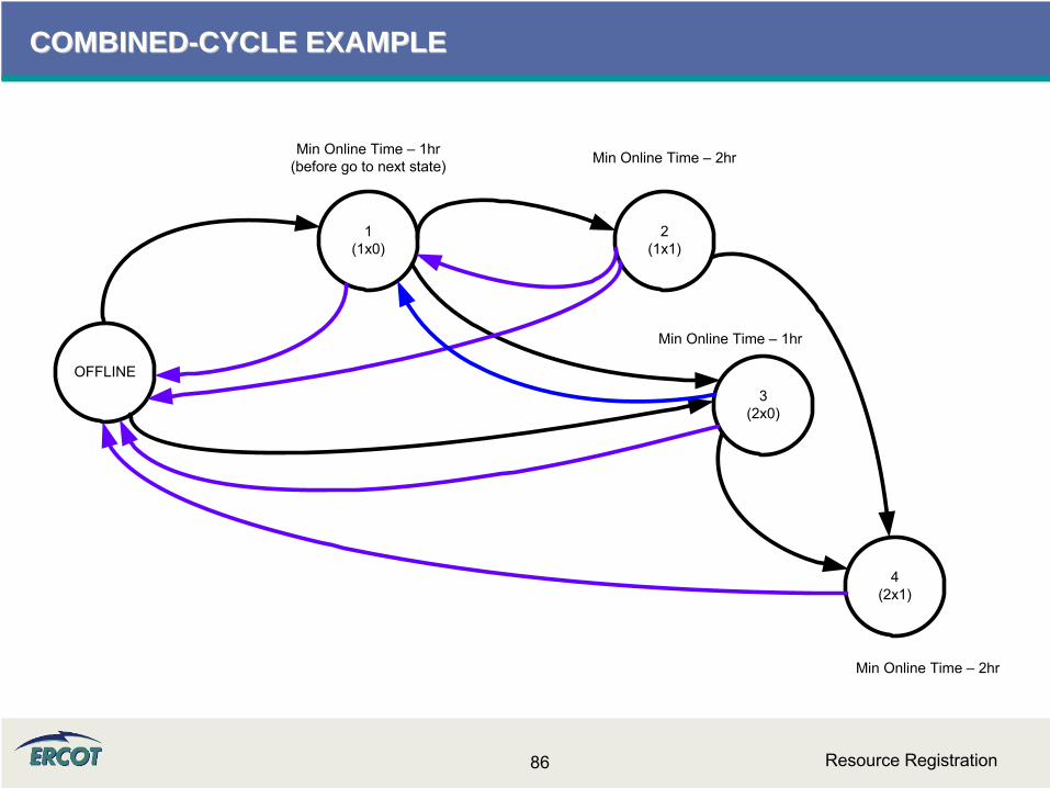
Resource Registration86
COMBINEDCOMBINED--CYCLE EXAMPLECYCLE EXAMPLE
OFFLINE3
(2x0)
4(2x1)
2(1x1)
1(1x0)
Min Online Time – 1hr(before go to next state) Min Online Time – 2hr
Min Online Time – 2hr
Min Online Time – 1hr

Resource Registration87
COMBINEDCOMBINED--CYCLE EXAMPLECYCLE EXAMPLE
•
Go to the RARF transition matrix.•
Referring to the state diagram constructed on the previous slide, each arrow should be an X in the matrix. –
An arrow from left to right will be entered as an X in the transition matrix above the black diagonal –
upward transition–
An arrow from right to left will be entered as an X in the transition matrix below the black diagonal –
downward transition•
Please keep in mind that the train will stay in a configuration for the duration of the minimum online time when transitioning up to the configuration.–
This time is not honored when transitioning down through configurations, i.e. when the previous configuration was higher.
1 2 3 2 3
Offline ABC_CC1_1 ABC_CC1_2 ABC_CC1_3 ABC_CC1_41 Offline X X2 ABC_CC1_1 X X X3 ABC_CC1_2 X X X2 ABC_CC1_3 X X X3 ABC_CC1_4 X
To
From .
Resource Registration88
COMBINEDCOMBINED--CYCLE EXAMPLECYCLE EXAMPLE
OFFLINE3
(2x0)
4(2x1)
2(1x1)
1(1x0)
Min Online Time – 1hr(before go to next state) Min Online Time – 2hr
Min Online Time – 2hr
Min Online Time – 1hr1 2 3 2 3
Offline ABC_CC1_1 ABC_CC1_2 ABC_CC1_3 ABC_CC1_41 Offline X X2 ABC_CC1_1 X X X3 ABC_CC1_2 X X X2 ABC_CC1_3 X X X3 ABC_CC1_4 X
To
From .
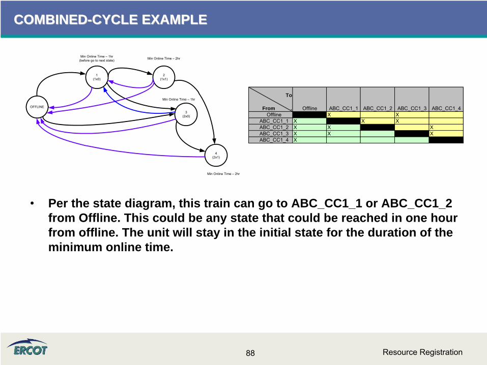
•
Per the state diagram, this train can go to ABC_CC1_1 or ABC_CC1_2 from Offline. This could be any state that could be reached in one hour from offline. The unit will stay in the initial state for the duration of the minimum online time.
Resource Registration89
COMBINEDCOMBINED--CYCLE EXAMPLECYCLE EXAMPLE
OFFLINE3
(2x0)
4(2x1)
2(1x1)
1(1x0)
Min Online Time – 1hr(before go to next state) Min Online Time – 2hr
Min Online Time – 2hr
Min Online Time – 1hr1 2 3 2 3
Offline ABC_CC1_1 ABC_CC1_2 ABC_CC1_3 ABC_CC1_41 Offline X X2 ABC_CC1_1 X X X3 ABC_CC1_2 X X X2 ABC_CC1_3 X X X3 ABC_CC1_4 X
To
From .
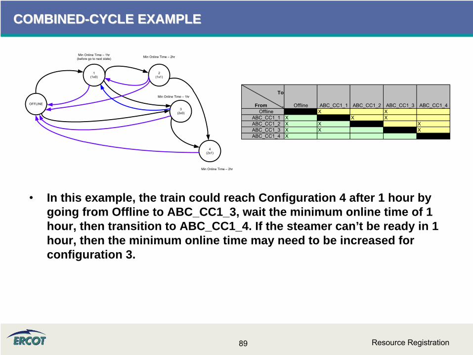
•
In this example, the train could reach Configuration 4 after 1 hour by going from Offline to ABC_CC1_3, wait the minimum online time of 1 hour, then transition to ABC_CC1_4. If the steamer can’t be ready in 1 hour, then the minimum online time may need to be increased for configuration 3.
Resource Registration90
COMBINEDCOMBINED--CYCLE EXAMPLECYCLE EXAMPLE
OFFLINE3
(2x0)
4(2x1)
2(1x1)
1(1x0)
Min Online Time – 1hr(before go to next state) Min Online Time – 2hr
Min Online Time – 2hr
Min Online Time – 1hr1 2 3 2 3
Offline ABC_CC1_1 ABC_CC1_2 ABC_CC1_3 ABC_CC1_41 Offline X X2 ABC_CC1_1 X X X3 ABC_CC1_2 X X X2 ABC_CC1_3 X X X3 ABC_CC1_4 X
To
From .
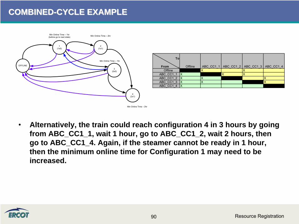
•
Alternatively, the train could reach configuration 4 in 3 hours by going from ABC_CC1_1, wait 1 hour, go to ABC_CC1_2, wait 2 hours, then go to ABC_CC1_4. Again, if the steamer cannot be ready in 1 hour, then the minimum online time for Configuration 1 may need to be increased.

Resource Registration91
COMBINEDCOMBINED--CYCLE CYCLE –– FAQFAQ
•
Do the start times apply to the plant or to the configuration? –
Currently, these times are used to determine if a configuration is available to start up in time for the first interval of the RUC study period. If a unit in the train is already online, start times do
not apply.
•
How do we fill this out for combined-cycle resources, as breaker close is before we reach LSL and before the steamer is on? –
The times are for start-up, not transitional. So time to close breaker is from start-up of the train.
•
What if there are multiple breakers?–
Provide time from initiating start to the last breaker to close in achieving the registered configuration.
Resource Registration92
COMBINEDCOMBINED--CYCLE CYCLE –– FAQFAQ
•
The highest MW the steamer can produce is based on the number of GTs that are running. For the high and low reasonability limits on the steamer - should the HRL represent the total MW that can be produced when ALL units are on or per GT? –
The reasonability limits should be set for each unit, as well as
each configuration and should span the abilities of the unit or configuration –
lowest to highest. The steamer LRL would be the low limit for the steamer output with only one 1 CT running and the HRL would be the high limit on the steamer with all CTs running.
•
Do Combined Cycle augmentations require a separate configuration?–
No. Power augmentations should be accounted for in the reasonability limits set for any configuration they could be used in, but should not be a separate configuration. The COP should reflect limits for actual operating conditions.
Resource Registration93
COMBINEDCOMBINED--CYCLE CYCLE –– FAQFAQ
•
We have CTs that are able to start up in a fraction of an hour. On some of the Resource Parameters, if we use whole numbers we are not representing the resource accurately. Do we still use whole numbers for these types of resources?–
Yes, please use whole numbers as the Resource Parameter section that references start times is used primarily for the Reliability Unit Commitment process, which is hourly.
•
Different turbines of our combined-cycle unit have different minimum loads depending on which configuration is operating. How do you want this expressed when filling out the RARF?–
The Reasonability limits and Sustainable / Emergency MW ratings should be filled out for each unit as well as each configuration.

Resource Registration94
COMBINEDCOMBINED--CYCLE CYCLE –– FAQFAQ
•
Do we need to register every configuration?–
No, we are asking for operationally unique configurations. For every CT that is reasonable, enter “X”
for the primary CT and enter “A”
for every alternate. At this time, an instruction would identify the configuration, and the selection of the unit (“X”
or any submitted “A”) is up to the entity.
•
Why do we need to enter the configurations as increasing MW and unit order?–
This will achieve two things. One, the transition matrix will fall out as “increasing”
above the diagonal, and “decreasing”
below the diagonal. Also, it will help to keep start-up costs aligned.
•
A long Minimum Online Time can have negative effects on RUC and may limit the movement of the train. Is there a way to slow the steamer only?–
Not at this time.
Resource Registration95
COMBINEDCOMBINED--CYCLE CYCLE –– FAQFAQ
•
How should split-bus situations be handled? Are we working with ABB to model split bus configurations better to avoid diverging dispatch instructions? –
Typically, a CC on two voltage levels inside ERCOT would be registered and treated as separate entities. A GT and ST on the
same grid could still be treated as combined cycle, and an individual GT on a different grid, for example, would be treated
as an independent, traditional generator. These circumstances may lead to a 0-on-1 configuration that can be registered.
–
The ABB request will be passed on to NMMS.
•
How should split-bus situations be handled if the (only) steamer is the odd unit connection?–
At this time, these units would all be independent, traditional generators and not combined cycle.
Resource Registration96
COMBINEDCOMBINED--CYCLE CYCLE –– FAQFAQ
•
We have a large Private Network CC, yet we’ll only have small portion of power going to grid. Do we still have to complete all operationally unique configurations? We can only sell power in one configuration. –
TBD
Network Model DataNetwork Model Data
Resource Registration98
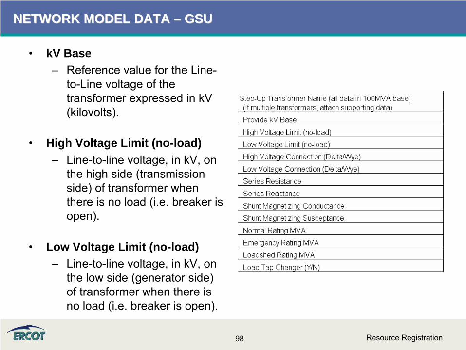
NETWORK MODEL DATA NETWORK MODEL DATA –– GSU GSU
•
kV Base–
Reference value for the Line-
to-Line voltage of the transformer expressed in kV (kilovolts).
•
High Voltage Limit (no-load)–
Line-to-line voltage, in kV, on the high side (transmission side) of transformer when there is no load (i.e. breaker is open).
•
Low Voltage Limit (no-load)–
Line-to-line voltage, in kV, on the low side (generator side) of transformer when there is no load (i.e. breaker is open).
Resource Registration99
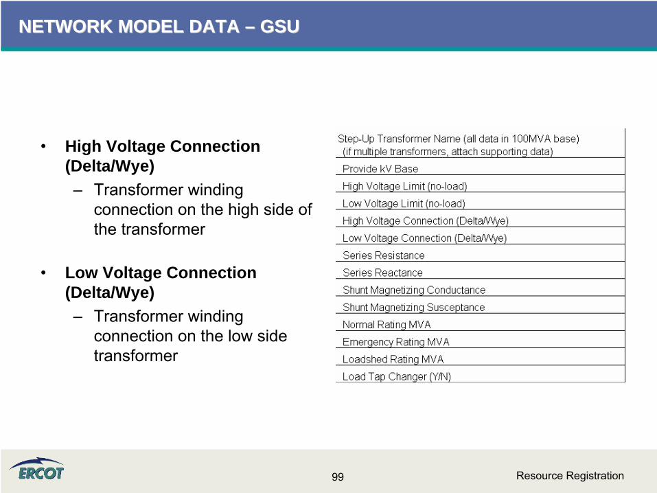
NETWORK MODEL DATA NETWORK MODEL DATA –– GSUGSU
•
High Voltage Connection (Delta/Wye)–
Transformer winding connection on the high side of the transformer
•
Low Voltage Connection (Delta/Wye)–
Transformer winding connection on the low side transformer

Resource Registration100
NETWORK MODEL DATA NETWORK MODEL DATA –– GSUGSU
•
Series Resistance (R1)–
Determined by “short-circuit test”
where the low-voltage side is short-circuited and enough voltage is applied on high-voltage terminals to circulate rated current.
–
This is the winding resistance per phase.
•
Series Reactance (X1)–
Determined by “short-circuit test”
where the low-voltage side is short-circuited and enough voltage is applied on high-voltage terminals to circulate rated current.
–
This is the winding reactance per phase.
•
Series Impedance, Z1 = R1 + jX1
Resource Registration101
NETWORK MODEL DATA NETWORK MODEL DATA –– GSUGSU
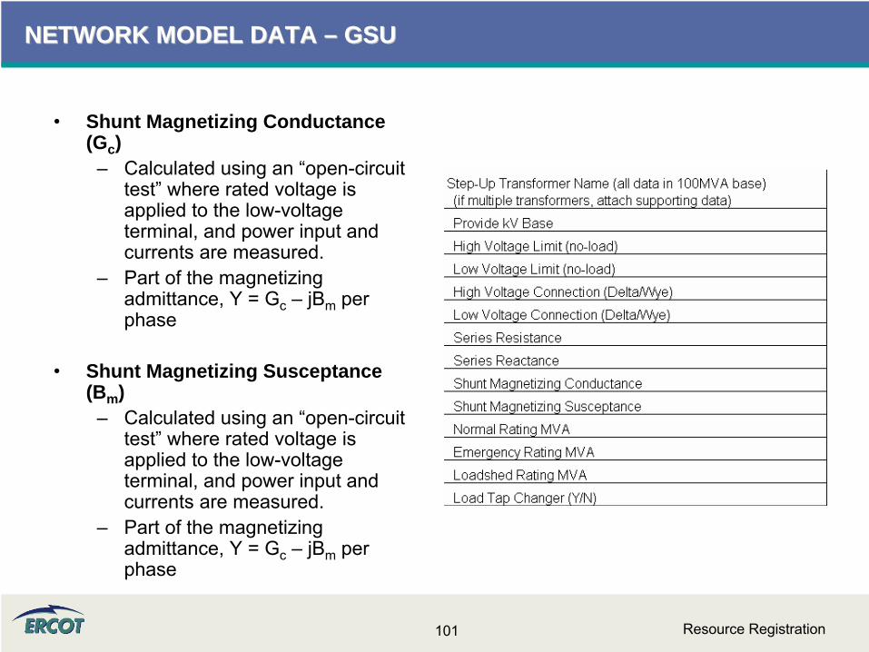
•
Shunt Magnetizing Conductance (Gc )
–
Calculated using an “open-circuit test”
where rated voltage is applied to the low-voltage terminal, and power input and currents are measured.
–
Part of the magnetizing admittance, Y = Gc
– jBm
per phase
•
Shunt Magnetizing Susceptance (Bm )
–
Calculated using an “open-circuit test”
where rated voltage is applied to the low-voltage terminal, and power input and currents are measured.
–
Part of the magnetizing admittance, Y = Gc
– jBm
per phase
Resource Registration102
NETWORK MODEL DATANETWORK MODEL DATA
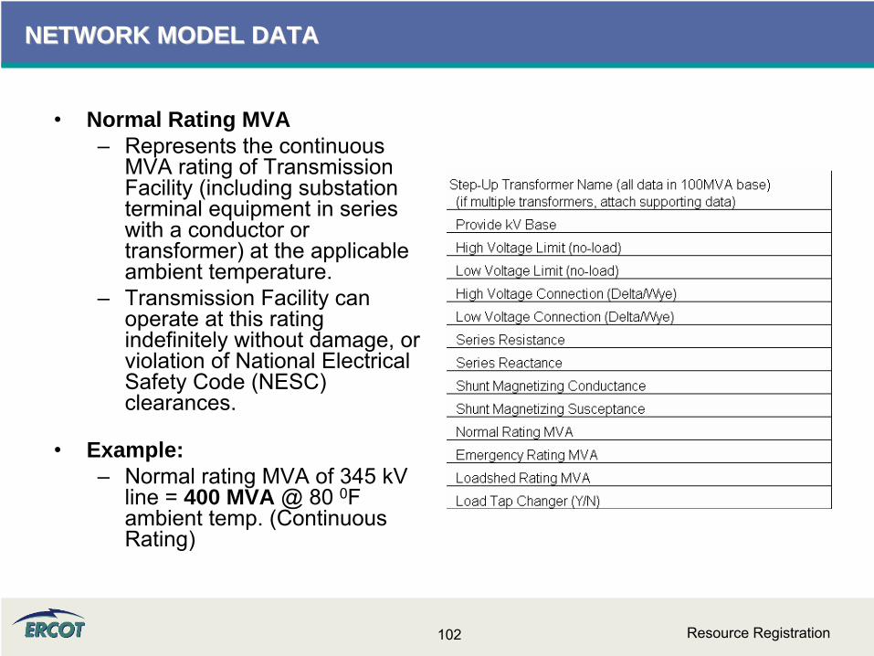
•
Normal Rating MVA–
Represents the continuous MVA rating of Transmission Facility (including substation terminal equipment in series with a conductor or transformer) at the applicable ambient temperature.
–
Transmission Facility can operate at this rating indefinitely without damage, or violation of National Electrical Safety Code (NESC) clearances.
•
Example:–
Normal rating MVA of 345 kV line = 400 MVA @ 80 0F ambient temp. (Continuous Rating)
Resource Registration103
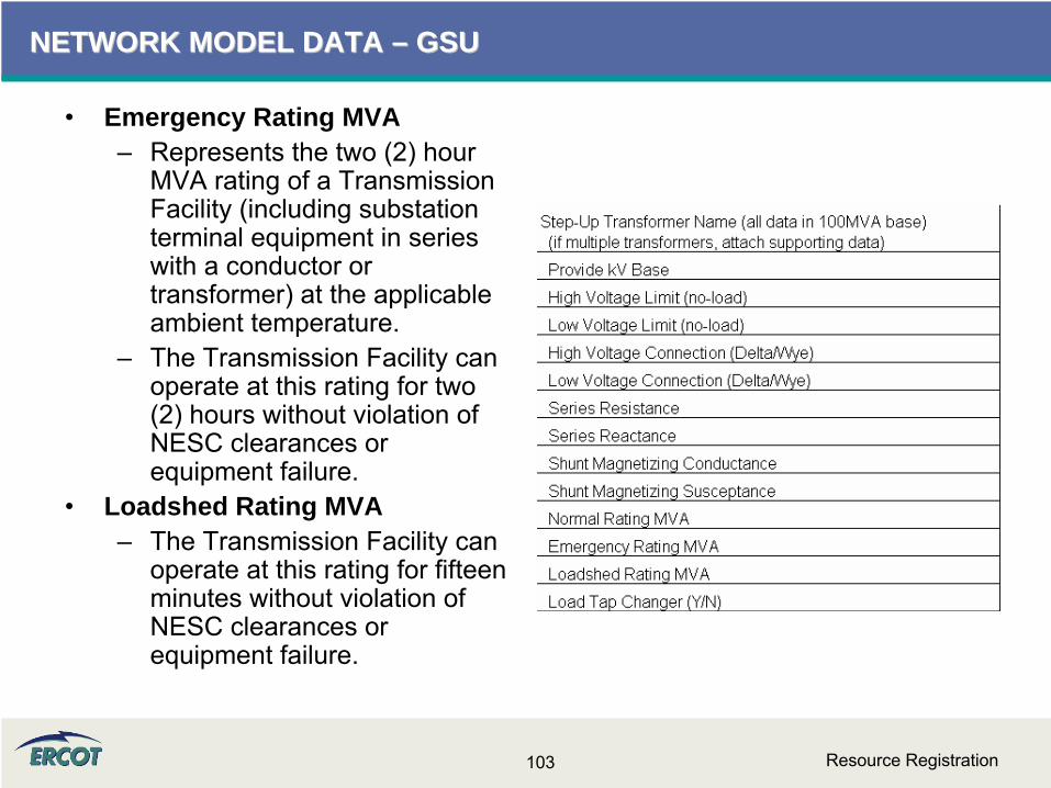
NETWORK MODEL DATA NETWORK MODEL DATA –– GSUGSU
•
Emergency Rating MVA–
Represents the two (2) hour MVA rating of a Transmission Facility (including substation terminal equipment in series with a conductor or transformer) at the applicable ambient temperature.
–
The Transmission Facility can operate at this rating for two (2) hours without violation of NESC clearances or equipment failure.
•
Loadshed Rating MVA–
The Transmission Facility can operate at this rating for fifteen minutes without violation of NESC clearances or equipment failure.

Resource Registration104

Resource Registration105
NETWORK MODEL DATA NETWORK MODEL DATA –– GSU TAP CHANGERGSU TAP CHANGER
•
Complete only section that applies to transformer–
Low side is Generator side–
High side is Transmission side
•
Nominal Voltage is design voltage in KV
•
Use positions not voltages
Resource Registration106
NETWORK MODEL DATA NETWORK MODEL DATA –– GSU FAQGSU FAQ
•
Where will the transformer names be found/listed/available on the RARF?–
Existing transformer names and PTI bus numbers can be found in the ERCOT Branch Data spreadsheet available in the Operations and System Planning secure area of the ERCOT website in the Operations Model data folder.
–
For new REs, the transformer name results can be obtained by one of several methods: The transmission operator dictates the name, the RE determines the name, the transmission and distribution service provider (TDSP) and RE work together to determine a name.

Resource Registration107
NETWORK MODEL DATA NETWORK MODEL DATA –– GSU FAQGSU FAQ
•
What do we do if we have more than one step-up transformer per unit?–
Attach additional transformer information with the RARF submittal.
–
The “New RARF”
will revisit this, allowing transformers to be registered, and then assigned to appropriate units
•
What do we do if we have multiple units for one step-up transformer? –
Enter the transformer information once, and put a reference in the “transformer name”
row for the other units.–
This will also be resolved in the “New RARF”
Resource Registration108
NETWORK MODEL DATA NETWORK MODEL DATA –– GSU FAQGSU FAQ
•
Can you give some detail as to what you are looking for when you ask us to "Provide kV Base”?–
The KV Base is needed to identify the base voltage used in the per unit calculations associated with the transformer data.
–
Electrical systems are often modeled on a per unit basis. In order to make per unit calculations useful to ERCOT, the base for MVA and KV must be disclosed.
–
For the step-up transformer, ERCOT has requested that the MVA Base is 100MVA. Even if the MVA Base is given, the resource needs to provide the kV Base in the RARF.
–
Use “Line-to-Line Voltage”
kV Base for uniformity
Resource Registration109
NETWORK MODEL DATA NETWORK MODEL DATA –– GSU FAQGSU FAQ
•
In the Network Model Transformer Data section, what is needed in the Low Voltage Limit and High Voltage Limit fields?–
The High Voltage Limit and the Low Voltage Limits for the transformers should be the no-load ratings.
–
On the EDS 4 RARF, these fields are labeled as: •
High Voltage Limit (no-load tap)•
Low Voltage Limit (no-load tap)–
These should read: •
High Voltage Limit (no-load)•
Low Voltage Limit (no-load)–
For example, the per-unit nominal voltage is 1.0, the no-load limits could be 1.1.

Resource Registration110
NETWORK MODEL DATA NETWORK MODEL DATA –– GSU FAQGSU FAQ
•
Where can I find existing transformer information? –
Much of the step-up transformer information is available in the ERCOT Branch Data file, which is available from the secure Operations and System Planning Data website, in the Operations Model folder. Please be aware this is a very, very large file.
•
Where do I find the transformer name?–
The Transformer name is in the ERCOT Branch Data file. The information is requested in per-unit. In order to calculate per-unit data, the MVA and KV base must be known. The per-unit data should be calculated with a 100MVA Base, and the (Line-to-Line Voltage) KV Base needs to be submitted. Additional information on the Conductance, Susceptance and MVA ratings can be found in the Glossary (see the Appendix).

Resource Registration111
NETWORK MODEL DATA NETWORK MODEL DATA –– ADDITIONAL ASSETSADDITIONAL ASSETS
•
Applies to ALL generation resources
•
Used to complete the model of the transmission system–
Capture lines and equipment other than the generator and step-up transformer that are owned and/or operated by the generation resource and not part of the operations of the TSP.
–
This information is needed for the ERCOT system model, and is required per the Nodal Protocols in section 3.10.7.
–
Examples include the transmission line to reach the first TSP-modeled substation or a capacitor bank in service between the generator and the TSP switching device.
•
Another resource for existing PTI model information includes the ERCOT Branch Data zip file found in the Operations and System Planning (OSP) secure website–
To login or to register for access for the OSP website, please go to http://oldercot.ercot.com/tmaps/login.cfm
–
Once a user is logged in, select the folder “Operations Model Data”
then select the zip file for ERCOT Branch Data.
Resource Registration112
NETWORK MODEL DATA NETWORK MODEL DATA –– ADDITIONAL ASSETSADDITIONAL ASSETS
Resource Registration113
NETWORK MODEL DATA NETWORK MODEL DATA –– ADDITIONAL ASSETSADDITIONAL ASSETS
Resource Registration114
NETWORK MODEL DATA NETWORK MODEL DATA –– ADDITIONAL ASSETSADDITIONAL ASSETS
Resource Registration115
NETWORK MODEL DATA NETWORK MODEL DATA –– ADDITIONAL ASSETSADDITIONAL ASSETS
•
ERCOT Branch Data can assist with filling this out–
Found in Operations Model Data folder on secure Operations and System Planning Website
–
http://oldercot.ercot.com/tmaps/login.cfm
•
Additional questions should be directed to [email protected] who will redirect to ERCOT Network Modeling
Resource Registration116
NETWORK MODEL DATA NETWORK MODEL DATA –– ADDITIONAL ASSETS FAQADDITIONAL ASSETS FAQ
•
The breaker ownership used to be the TSP and now is part of the generation company. Who should report this information?–
The entity that owns/represents the breaker should report it. –
If the TSP previously provided the information to ERCOT, it should be available in the ERCOT Branch Data file.
–
The generation entity should validate/verify the information if the current model is the source.

PLANNING DATAPLANNING DATA

Resource Registration118
PLANNING DATAPLANNING DATA
•
Identify the MVA base for the generator unit data–
Typically, this is 100 MVA (3-
phase) but not always. Check OEM data.
•
Identify the KV base for the generator unit data–
Typically, this is the Line-to-
Line Terminal Voltage
–
Example: Nameplate rating of Generator is 300 MVA, 13.8 kV, use kV base = 13.8 kV
•
Impedances should be provided in per unit of the machine base identified in this section.

Resource Registration119
PLANNING DATAPLANNING DATA
•
Identify time for breaker clear fault
•
Identify generator protection–
Voltage–
Frequency–
Instantaneous and up to three settings
Resource Registration120
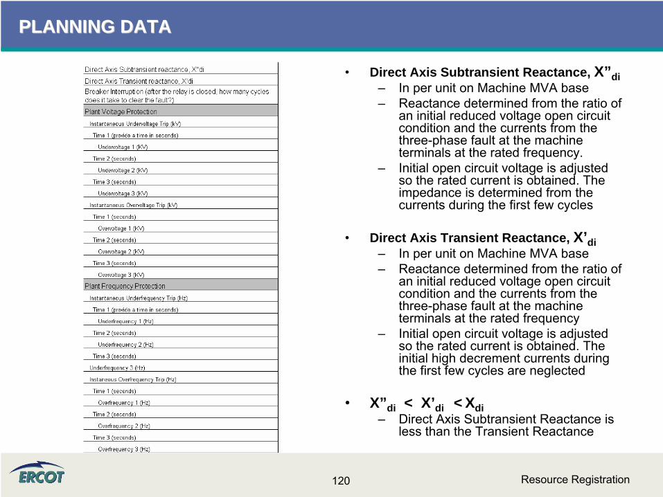
PLANNING DATAPLANNING DATA
•
Direct Axis Subtransient Reactance, X”di–
In per unit on Machine MVA base–
Reactance determined from the ratio of an initial reduced voltage open circuit condition and the currents from the three-phase fault at the machine terminals at the rated frequency.
–
Initial open circuit voltage is adjusted so the rated current is obtained. The impedance is determined from the currents during the first few cycles
•
Direct Axis Transient Reactance, X’di–
In per unit on Machine MVA base–
Reactance determined from the ratio of an initial reduced voltage open circuit condition and the currents from the three-phase fault at the machine terminals at the rated frequency
–
Initial open circuit voltage is adjusted so the rated current is obtained. The initial high decrement currents during the first few cycles are neglected
•
X”di < X’di < Xdi–
Direct Axis Subtransient Reactance is less than the Transient Reactance
Resource Registration121
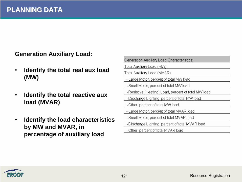
PLANNING DATAPLANNING DATA
Generation Auxiliary Load:
•
Identify the total real aux load (MW)
•
Identify the total reactive aux load (MVAR)
•
Identify the load characteristics by MW and MVAR, in percentage of auxiliary load
Resource Registration122
PLANNING INFORMATION PLANNING INFORMATION -- SITESITE
•
Load Characteristics –
Definition of large and small motor•
By voltage –
Connected 2400/4160V and above are large–
Connected below 2400/4160V are small
•
Percentages of MW should add up to 100%
•
Percentages of MVAR should add up to 100%
•
Load characteristics of generator auxiliary load are not assumed to be the same as the load characteristics of the private networks.
•
Give most information with a reasonable amount of effort–
Guesses and inaccuracies cause model to be inaccurate
Resource Registration123
PLANNING DATAPLANNING DATA
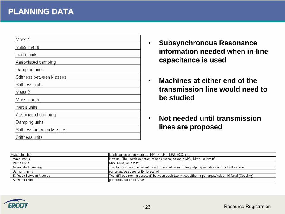
•
Subsynchronous Resonance information needed when in-line capacitance is used
•
Machines at either end of the transmission line would need to be studied
•
Not needed until transmission lines are proposed
Resource Registration124
PLANNING DATAPLANNING DATA
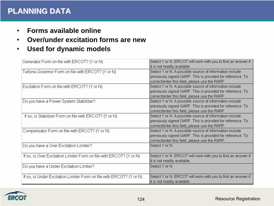
•
Forms available online •
Over/under excitation forms are new•
Used for dynamic models

Resource Registration125
PLANNING DATA PLANNING DATA –– FAQFAQ
•
Does ERCOT want the generator Zero Sequence impedance of just the generator windings, or do they want the generator and the neutral grounding transformer impedance in this blank? –
The impedance should include the machine impedance plus neutral grounding impedance (if any).
–
This section came from the Generation Data Forms Detailed Gen Info-by unit tab for Transient Stability Analysis. ERCOT is looking for generator impedances in R + jX form.

Resource Registration126
PLANNING DATA PLANNING DATA –– FAQFAQ
•
We need a better definition of what is being asked for in the Generation Details Section labeled as "Mutual coupling Armature-Rotor Z". This appears to be asking for the mutual inductance between the stator and the rotor in the generator.–
The three pieces of information –
Armature, Rotor, Mutual Coupling –
should be provided together. –
Alternatively, the Zeq could be submitted in the first row of this section in lieu of the individual impedance components.
–
This section came from the Generation Data Forms Detailed Gen Info-by unit tab for Transient Stability Analysis. ERCOT is looking for the machine impedances in R + jX form.
Resource Registration127
PLANNING DATA PLANNING DATA –– FAQFAQ
•
What is Armature Z? What is Rotor Z? What is Mutual coupling Armature-Rotor Z? –
The Armature impedance would also be the Stator impedance. –
These three components (Armature, Rotor, and Mutual Coupling of Armature and Rotor) are used to calculate an equivalent impedance for the unit, Zeq.
•
Is Machine Impedance the same as Positive Sequence?–
Machine Impedance (Z) row should be the Zeq if available.
Resource Registration128
PLANNING DATA PLANNING DATA –– FAQFAQ
•
Do we need to be including the alarms and operator's guides for manual trip times in this section or is it OK to omit any information based on the fact that these are not automatic trips?–
If there are no automatic trips, please enter N/A and use the comments section to the right to document why.
•
When filling out the RARF, if we have multiple voltage trip settings, one at a higher voltage as a back-up to another, which one do you want?–
The most current version of the RARF has space available to report multiple voltage and frequency trip settings.
•
Breaker Interruption Time (RARF) – What breaker is being referred to?–
The breaker that protects the generator

Resource Registration129
PLANNING DATA PLANNING DATA –– FAQFAQ
•
What is the definition of large motor? Over 1,000 HP, or what size? Or by voltage such as 13.8 KV motor? 480 V motor? What is the definition of small motor? such as less than 10 HP or what size? Or by voltage?–
As a suggestion, split the motors by voltage. Further defined, anything connected to 2400/4160V and higher would be considered large motors. Anything connected below that voltage level would be considered small.
–
This definition should improve accuracy and reduce time, as the motors information could be gathered and summarized beginning with the electrical connection.
•
My Turbine Rating is a curve. The output is based on steam inlet temp. What value do I fill in? –
This should be gross, the maximum MW the turbine is designed for.

Resource Registration130
PLANNING DATA PLANNING DATA –– FAQFAQ
•
The section covering SubSync Resonance is asking for some information that is unavailable. We have mass and inertia information on the Generator rotor/exciter and we have this same type of information on the turbine but we do not have the individual turbine rotating component (LP, HP, IP etc.) or between the generator rotor and exciter rotating elements. Also, we do not have any information on damping or stiffness on any of these items. If this information is necessary, it will require performing a study by the original OEMs and will come at a considerable cost per unit.–
The studies using this information are not completed often right
now, but will become more common as capacitor compensation is used in series on long transmission lines.
–
The studies focus on the units at either end of the lines compensated with the series capacitors to ensure the resonance from these lines won’t excite critical frequencies in the machines in the area at the
end of these lines.
–
Owners of these units will be interested in these studies to prevent equipment damage.
–
ERCOT will accept minimal information in these fields at this time, but as series compensation is installed on our grid, this information will become necessary and critical to system performance.

Resource Registration131
PLANNING DATA PLANNING DATA –– FAQFAQ
•
Will ERCOT be updating their site with all the new manufactures model sheets? Where can we get copies of the latest model sheets?–
PTI Dynamic Models can be found in the Generation Project Interconnection Information folder on the Operations and System Planning secure website at:
http://www.ercot.com/tmaps/ListMaps.cfm?GroupID=50–
In addition, some models can be found on ERCOT.com at:http://www.ercot.com/gridinfo/generation/index.html
–
ERCOT’s standard models are obtained from PSSE manuals–
Non-standard models, typically new generator designs, will have to be generated and submitted by the resource

Private Network InformationPrivate Network Information

Resource Registration133
PRIVATE NETWORK INFORMATIONPRIVATE NETWORK INFORMATION
•
Please note that we are asking for gross totals as well as net values for the specific rows. A simple check would be to follow the equation below:
•
Net Interchange = Gross Capability – Self Serve Load
Resource Registration134
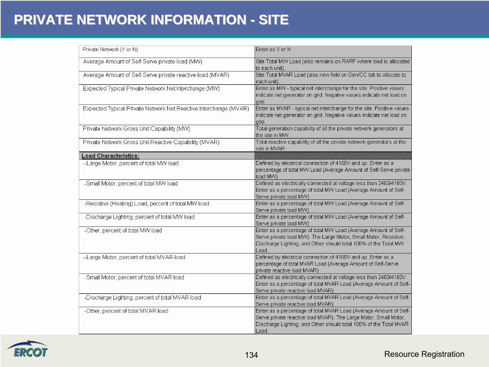
PRIVATE NETWORK INFORMATION PRIVATE NETWORK INFORMATION -- SITESITE
Resource Registration135
PRIVATE NETWORK INFORMATION PRIVATE NETWORK INFORMATION -- SITESITE
•
Load Characteristics PN load–
Definition of large and small motor•
By voltage –
Connected 2400/4160V and above are large–
Connected below 2400/4160V are small
•
Percentages of MW should add up to 100%
•
Percentages of MVAR should add up to 100%
•
Load characteristics of generator auxiliary load are not assumed to be the same as the load characteristics of the private networks.
•
Give most information with a reasonable amount of effort–
Guesses and inaccuracies cause model to be inaccurate

Resource Registration136
PRIVATE NETWORK INFORMATION PRIVATE NETWORK INFORMATION -- UNITUNIT
•
Gross Gen, Load, Net Interchange–
MW and MVAR by unit–
All units should sum to total for site
•
Load trip–
Identify if load trips when unit trips
–
Identify percentage of load (as allocated to that unit) that will trip

Resource Registration137
PRIVATEPRIVATE--USE NETWORK USE NETWORK –– FAQ FAQ
•
Our units are dual-grid (i.e. outside of ERCOT). Are we a private network? –
No, this is not considered a private network. ERCOT will be requesting the information for the tie line into the ERCOT Grid, as well as
other components that are not currently modeled in ERCOT, in order to ensure the model is accurate
•
Does "Private Network" exclude auxiliary/house power in generating stations? –
Yes. Please include all auxiliary/house power in generating stations separately in the Additional Planning Data section under “Generation Auxiliary Load”.
•
For private network, what are the High/Low Reasonability Limits?–
The Highest and Lowest amount of power that could be injected into the ERCOT grid from that unit, depending on unit capabilities and swing of the industrial load behind the fence.


