

RF Ranging for Indoor Tracking and Positioning
WPI Technology Workshop: Precision Indoor Personnel
Location and Tracking for Emergency Responders
Dennis McCrady
Robert Goldberg
Tim Pfister
August 7, 2006
WPI Technology Workshop: Precision Indoor Location and Tracking for Emergency Responders l August 7, 2006 l 2
RF Ranging for Indoor Tracking and Positioning
Agenda
• Background
• RF Ranging System Description
• Keys to Accurate RF Ranging
• RF Ranging Performance
– Laboratory
– Field (Over the Air)
• ITT Software Defined Radios (SDR)
• Conclusions

WPI Technology Workshop: Precision Indoor Location and Tracking for Emergency Responders l August 7, 2006 l 3
RF Ranging for Indoor Tracking and Positioning
Background
• GPS provides excellent accuracy in areas where it can be received
• Satellite navigation improvements are on the horizon
– GPS III and Galileo
– When?
– What improvements will finally be implemented?
• In the meantime, GPS restricted environments require multiple technologies in a blended solution
– Use GPS when available
– Inertial sensors (MEMS are feasible)
– RF ranging systems (TOA, DTOA, AOA)
• Focus on RF ranging (TOA) technology developed at ITT
– Implemented within a direct sequence spread spectrum communication system
– Utilizes waveforms, modem, and networking protocol to facilitate the RF ranging application
WPI Technology Workshop: Precision Indoor Location and Tracking for Emergency Responders l August 7, 2006 l 4
RF Ranging for Indoor Tracking and Positioning
RF Ranging System Description
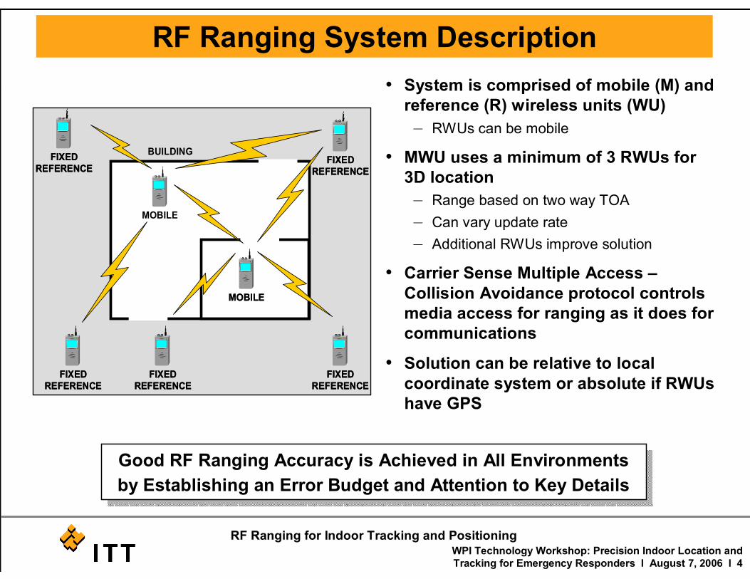
• System is comprised of mobile (M) and reference (R) wireless units (WU)
– RWUs can be mobile
• MWU uses a minimum of 3 RWUs for 3D location
– Range based on two way TOA
– Can vary update rate
– Additional RWUs improve solution
• Carrier Sense Multiple Access –Collision Avoidance protocol controls media access for ranging as it does for communications
• Solution can be relative to local coordinate system or absolute if RWUs have GPS
MOBILE
FIXEDREFERENCE
MOBILE
FIXEDREFERENCE
FIXEDREFERENCE
FIXEDREFERENCE
FIXEDREFERENCE
BUILDING
MOBILE
FIXEDREFERENCE
FIXEDREFERENCE
MOBILEMOBILE
FIXEDREFERENCE
FIXEDREFERENCE
FIXEDREFERENCE
FIXEDREFERENCE
FIXEDREFERENCE
FIXEDREFERENCE
FIXEDREFERENCE
FIXEDREFERENCE
BUILDING
Good RF Ranging Accuracy is Achieved in All Environments
by Establishing an Error Budget and Attention to Key Details

WPI Technology Workshop: Precision Indoor Location and Tracking for Emergency Responders l August 7, 2006 l 5
RF Ranging for Indoor Tracking and Positioning
• No permanent infrastructure
– Two-way ranging eliminates need for synchronized clocks
– 1 ppm clocks are sufficient
– Internal delay calibration
• Use optimum carrier frequency for propagation in buildings and urban areas: 300-450 MHz
• Use the highest achievable bandwidthsupported by the frequency allocation (Crammer Rao Bound):
CRB = 1/(BW x SNR1/2)
• Use a two part TOA ranging waveform: acquisition then TOA synchronization symbols
• Leading edge curve fitting to minimize multipath (MP) effects
• Quadrature Multi-Frequency Ranging (QMFR) for multipath mitigation – ITT patented technique
Keys to Accurate RF Ranging
NIJ-005
Note: 1) 1 <= N1 <= 128
2) 384 <= N2 <= 511
Mod Turn-On & AGC
Setting Times (N1
Symbols, 128 Chips per
Symbol)
TOASynchronization
2 Symbols
(1023 Chips per
Symbol)
Acquisition Sequence (16
Symbols, 128 Chips per
Symbol)
MultipathWindow
(N2 Chi ps)
Mod Turn-Off Time
(10 Symbols, 128 Chips
per Symbol)
TOA Ranging Waveform
Two Part Ranging Waveform Reduces Required Processing
Main PathCorrelationFunction
MultipathCorrelationFunction
Distorted Leading Edge of Correlation
Function(Main Path + Multipath)
NIJ_003
Main PathCorrelationFunction
MultipathCorrelationFunction
Distorted Leading Edge of Correlation
Function(Main Path + Multipath)
NIJ_003
MP Distorts the Correlation Function Used for TOA
WPI Technology Workshop: Precision Indoor Location and Tracking for Emergency Responders l August 7, 2006 l 6
RF Ranging for Indoor Tracking and Positioning
Performance - Laboratory
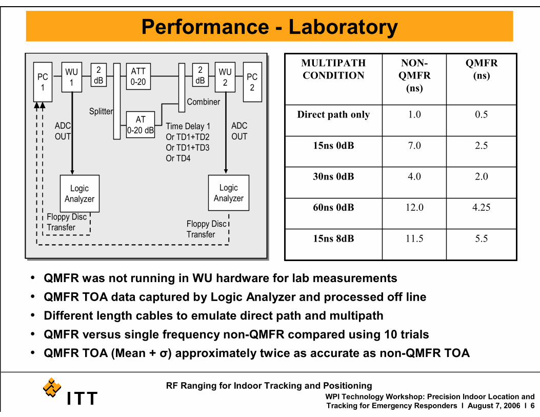
• QMFR was not running in WU hardware for lab measurements
• QMFR TOA data captured by Logic Analyzer and processed off line
• Different length cables to emulate direct path and multipath
• QMFR versus single frequency non-QMFR compared using 10 trials
• QMFR TOA (Mean + σ) approximately twice as accurate as non-QMFR TOA
PC
1
WU
1
2
dB
Logic
Analyzer
ATT
0-20
AT
0-20 dB
2
dBWU
2PC
2
Combiner
Time Delay 1
Or TD1+TD2
Or TD1+TD3
Or TD4
ADC
OUT
Splitter
ADC
OUT
Floppy Disc
Transfer Floppy Disc
Transfer
Logic
Analyzer
PC
1
WU
1
2
dB
Logic
Analyzer
ATT
0-20
AT
0-20 dB
2
dBWU
2PC
2
Combiner
Time Delay 1
Or TD1+TD2
Or TD1+TD3
Or TD4
ADC
OUT
Splitter
ADC
OUT
Floppy Disc
Transfer Floppy Disc
Transfer
Logic
Analyzer
5.511.515ns 8dB
4.2512.060ns 0dB
2.04.030ns 0dB
2.57.015ns 0dB
0.51.0Direct path only
QMFR
(ns)
NON-
QMFR
(ns)
MULTIPATH
CONDITION

WPI Technology Workshop: Precision Indoor Location and Tracking for Emergency Responders l August 7, 2006 l 7
RF Ranging for Indoor Tracking and Positioning
Performance – Field (Over the Air)
• Testing conducted at McKenna MOUT area of Fort Benning, Georgia
• 1 MWU and 5-8 RWUs that included GPS coordinates – QMFR not used
• RWUs were 1-750m from the MWU and the TOA update rate was 1/second
• TOA integrated with IMU and baro – results were driven by TOA accuracy
• Phase 3 waveform improvements resulted in establishing a .5m CEP accuracy limit and greatly improved accuracy in the harsh environments
Metric Phase 2 Measured Performance (m)
Circular Error Probable
Phase 3 Measured Performance (m)
Circular Error Probable
Phase 3 Measured Performance (m)
95 %
Goal (m) 95%
Horizontal Position Accuracy – Open Terrain
Not Measured 0.45 0.70 10
Horizontal PositionAccuracy – Urban Terrain
8.2 3.1 7.9 3
Horizontal Position Accuracy – In Building Terrain
13.8 4.8 7.0 1
Horizontal Position Accuracy – Forest Terrain
66.5 3.9 8.6 10
Vertical Position Accuracy – In Building Terrain
19.9 0.35 1.0 1

WPI Technology Workshop: Precision Indoor Location and Tracking for Emergency Responders l August 7, 2006 l 8
RF Ranging for Indoor Tracking and Positioning
ITT Software Defined Radios

WPI Technology Workshop: Precision Indoor Location and Tracking for Emergency Responders l August 7, 2006 l 9
RF Ranging for Indoor Tracking and Positioning
ITT Sensor Radio
ITT Actively Working on Design for Low Cost Sensor Radio with Production Goal of $500
SDR for Unattended Sensors
3.3” x 3” x 1”
Prototypes
Available

WPI Technology Workshop: Precision Indoor Location and Tracking for Emergency Responders l August 7, 2006 l 10
RF Ranging for Indoor Tracking and Positioning
ITT Wearable Soldier Radio
Technical Description� 1 Mbps and 2.6 Mbps at 1.2 MHz BW
� SCA 2.2 Compliant
� Supports Voice, Data, Video traffic
� UHF 225-450 MHz; Up to 5 W Xmit power
� Range: 2 Km open field, 1 km Urban
� Type III COMSEC, Type 1 Upgradeable
� Internal Commercial GPS Receiver
� Interfaces: Ethernet, USB, RS-232, Headset
� SWAP: 24 Cu In, 1.2 lbs, < 5W avg power
� Includes adaptive power management
� Prototype Available Now
� EDM Available Fall 2006
� Radio (Wearable and Handheld) for Dismounted Soldiers
� Provides CNR voice for dismounted units
� Radio automatically generates position report without the need for attached PDA
� Demonstrated integration with FBCB2 for SA data collection and display
� Demonstrated Tactical Internet interoperation
� Simple HMI minimizes training and operator interaction during mission
Operational Description
WPI Technology Workshop: Precision Indoor Location and Tracking for Emergency Responders l August 7, 2006 l 11
RF Ranging for Indoor Tracking and Positioning
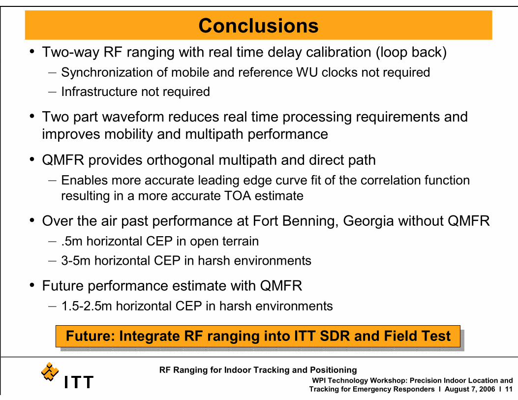
Conclusions• Two-way RF ranging with real time delay calibration (loop back)
– Synchronization of mobile and reference WU clocks not required
– Infrastructure not required
• Two part waveform reduces real time processing requirements and
improves mobility and multipath performance
• QMFR provides orthogonal multipath and direct path
– Enables more accurate leading edge curve fit of the correlation function
resulting in a more accurate TOA estimate
• Over the air past performance at Fort Benning, Georgia without QMFR
– .5m horizontal CEP in open terrain
– 3-5m horizontal CEP in harsh environments
• Future performance estimate with QMFR
– 1.5-2.5m horizontal CEP in harsh environments
Future: Integrate RF ranging into ITT SDR and Field Test
