

Thomas RoserMIT seminar
November 30, 2004
RHIC - the high luminosity hadron collider
RHIC overview
Luminosity and polarization evolution
Performance limitations
Future upgradesRHIC II luminosity upgradeeRHIC
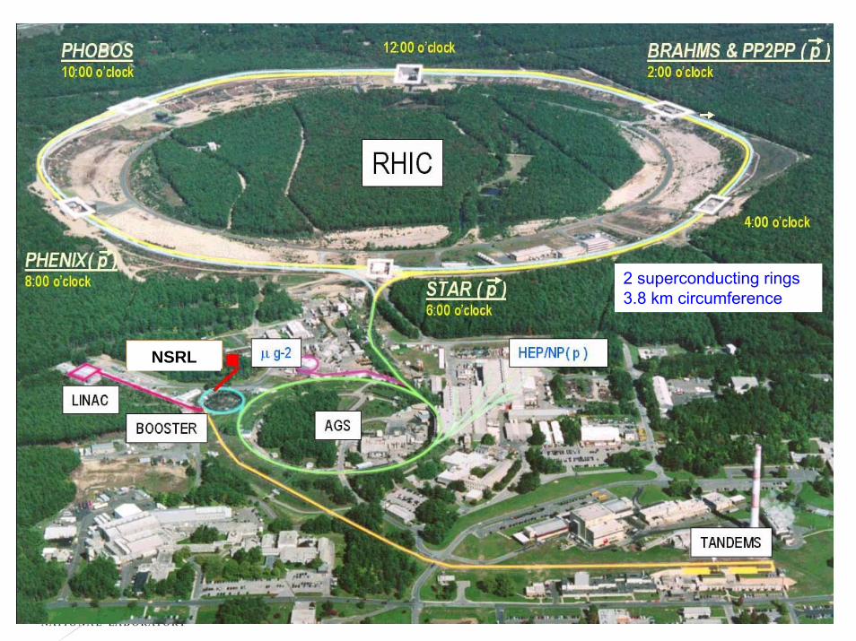
NSRL
2 superconducting rings3.8 km circumference

A Mini-Bang: Nuclear matter at extreme temperatures and density
Colliding gold at 100 + 100 GeV/nucleon (40 TeV total cm energy)Plus: other species (p-p, Cu-Cu (Run-5), …)
asymmetric collisions (d-Au, p-Au (?))several energies (100+100, 65+65, 32+32, 10+10)
a. Formation phase -parton scattering
b. Hot and dense phase -quark-gluon plasma and hadron gas ? → strongly interacting hot dense material
(sQGP)c. Freeze-out –
emission of hadrons
Produce and explore a new state of matter

Hard Scattering at RHIC
p+p →jet+jet (STAR 200 GeV)
Au+Au →???
(STAR 200 GeV/nucleon pair)
pp data
Central Au+Au collisions

RHIC Spin Physics
Spinning Proton Spinning Proton
Spinning Quarks or Gluons
Quark, Gluon, Photon,Electron or Neutrino fromW or Z Decay
• Spin structure functions of gluon and anti-quarks• Parity violation in parton-parton scattering• Requires high beam polarization and high luminosity

Gold Ion Collisions in RHIC
RHIC
AGSBOOSTER
TANDEMS
9 GeV/uQ = +79
1 MeV/uQ = +32
Beam Energy = 100 GeV/u

RHIC design, achieved and enhanced design parameters
Mode No ofbunches
Ions/bunch [109]
β*[m]
Beampolarization
Lpeak[cm-2s-1]
A1A2Lstore ave[cm-2s-1]
Design values (1999)
8×1026
5×1030
15×1026
5×1030
15×1030
30×1026
80×1030
8×1030
4×1030
16×1030
4×1030
p – p 56 170 1 10×1030 10×1030
31×1030
45%
Achieved values (2004)
Enhance design values (2008)
65×103070%
Lstore ave[cm-2s-1]
Au – Au 56 1.0 2 2×1026
p – p 56 100 2 4×1030
Au – Au 45 1.1 1 4×1026
p↑ – p↑ 56 70 1 4×1030
Au – Au 112 1.1 1 8×1026
p↑ – p↑ 112 200 1 65×1030
*
2
23
εβNN
MEf Brev=L
Other high luminosity hadron colliders:achieved goal scaled to 200 GeV
Tevatron (2 TeV) 100×1030 200×1030 20×1030
LHC (14 TeV) 10000×1030 140×1030

RHIC luminosity evolution
Nucleon-pair luminosity A1A2L allows comparison of different species.
Luminosity increased by 2 orders of magnitude in 4 years.
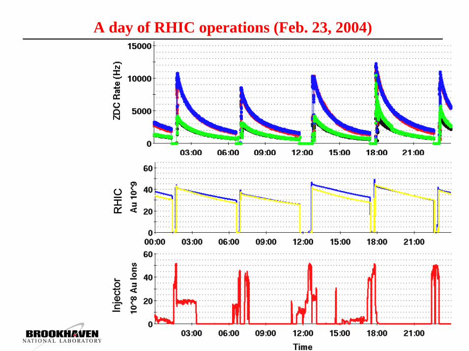
A day of RHIC operations (Feb. 23, 2004)
Inje
ctor
RH
IC

Performance Limitations
Intra-beam scattering (heavy ions)
Dynamic pressure rises
Instabilities
Beam-beam (light ions and protons)
Polarization (protons)
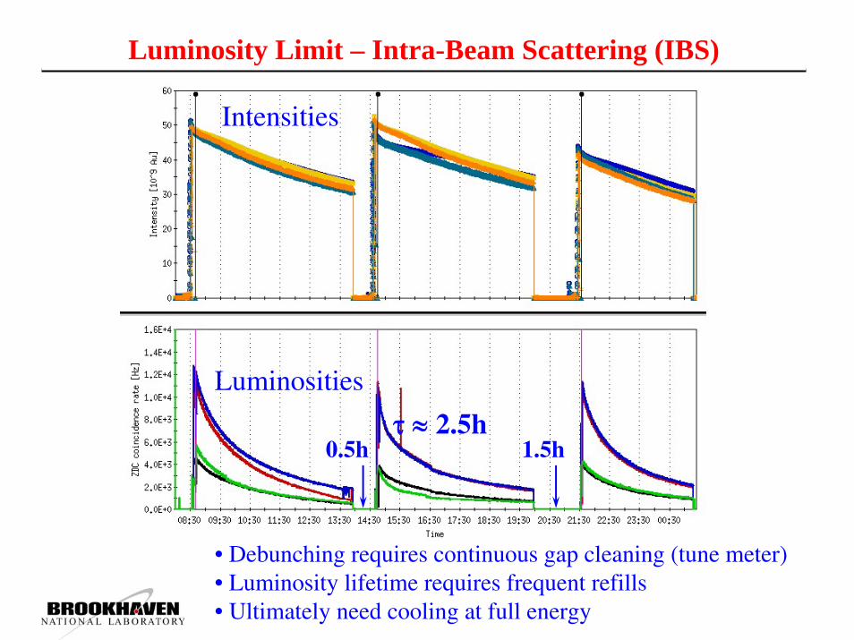
Luminosity Limit – Intra-Beam Scattering (IBS)
• Debunching requires continuous gap cleaning (tune meter)• Luminosity lifetime requires frequent refills• Ultimately need cooling at full energy
Intensities
Luminosities
τ ≈ 2.5h0.5h 1.5h

Intra-Beam Scattering (IBS) in RHIC
Longitudinal and transverse emittance growth agrees well with model
Some additional source of transverse emittance growth
Deuteron and gold beams are different because of IBS
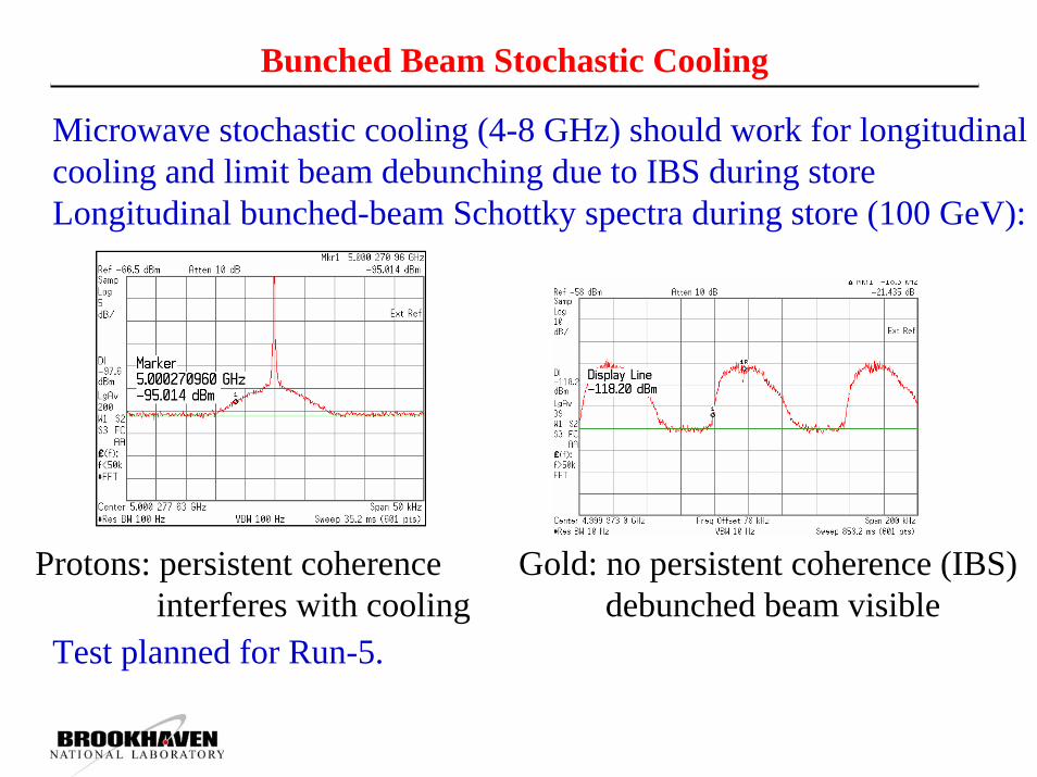
Bunched Beam Stochastic Cooling
Microwave stochastic cooling (4-8 GHz) should work for longitudinal cooling and limit beam debunching due to IBS during storeLongitudinal bunched-beam Schottky spectra during store (100 GeV):
Test planned for Run-5.
Protons: persistent coherenceinterferes with cooling
Gold: no persistent coherence (IBS)debunched beam visible

Luminosity Limits – Dynamic Pressure Rises86·1011 p+ total, 0.78·1011 p+/bunch, 110 bunches, 108 ns spacing
12 min
electron density and pressure rise
total beam intensity
Ubaldo Iriso
All operational relevant pressure rises can be explained by electron clouds
→ NEG (non-evaporative getter) coated beam pipes installed in warm areas

Luminosity Limits – Fast Instability Near TransitionTomographic reconstructionof 2D bunch density
• Fast transverse instability (~ GHz)• High sensitivity around transition• Effect of broadband impedance, electron cloud (?)
• Cures: beam-beam tune spread, octupoles, cross zero-chromaticity before transition (why?)
After instability with ~ 10 ms growth rate
Before instability

Luminosity Limits – Beam-Beam Interaction
Beam lifetime with different number of collisions, ξ=0.003/IP(due to abort gaps some bunches see only 2 or 3 collisions per turn)
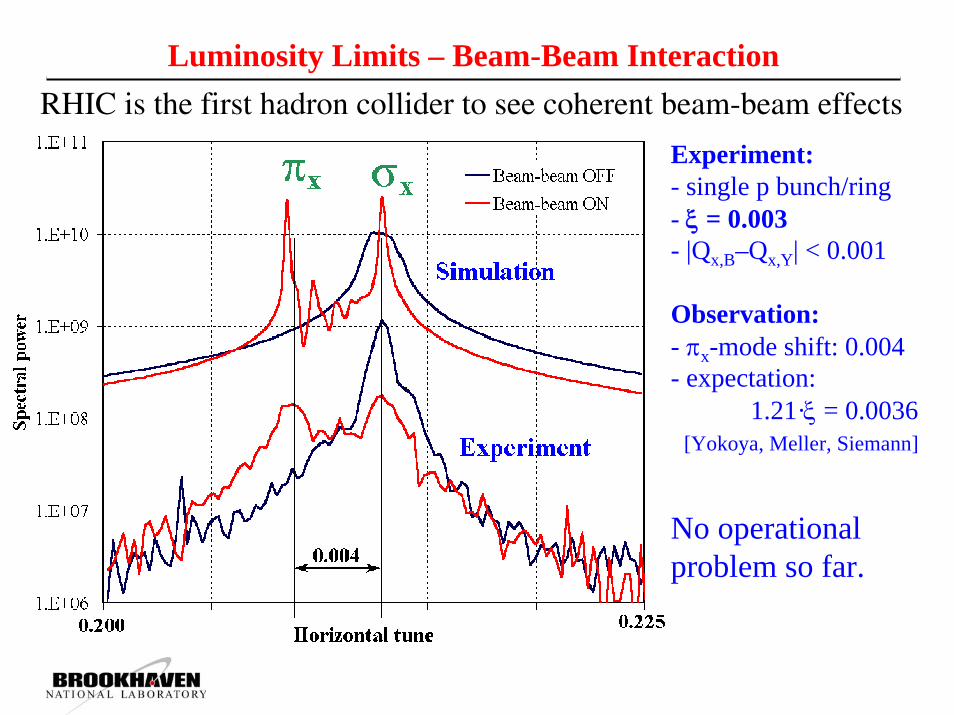
Luminosity Limits – Beam-Beam Interaction
Experiment:- single p bunch/ring- ξ = 0.003- |Qx,B–Qx,Y| < 0.001
Observation:- πx-mode shift: 0.004- expectation:
1.21·ξ = 0.0036[Yokoya, Meller, Siemann]
No operational problem so far.
4096 turn spectraRHIC is the first hadron collider to see coherent beam-beam effects
Luminosity Limits – Betatron Tune Working Point
Loss
rat
e
working point during ramp
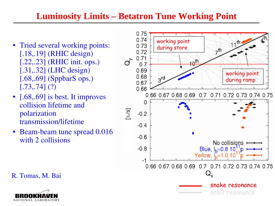
working point during store• Tried several working points:
[.18,.19] (RHIC design)[.22,.23] (RHIC init. ops.)[.31,.32] (LHC design)[.68,.69] (SppbarS ops.)[.73,.74] (?)
• [.68,.69] is best. It improves collision lifetime and polarization transmission/lifetime
• Beam-beam tune spread 0.016 with 2 collisions
R. Tomas, M. Bai Qx
Qy
snake resonanceorbit resonance

RHIC polarized proton accelerator complex
BRAHMS & PP2PP
STAR
PHENIX
AGS
LINACBOOSTER
Pol. H- Source
Spin Rotators(longitudinal polarization)
Solenoid Partial Siberian Snake
Siberian Snakes
200 MeV Polarimeter AGS Internal Polarimeter
Rf Dipole
RHIC pC PolarimetersAbsolute Polarimeter (H↑ jet)
AGS pC PolarimetersStrong AGS Snake
Helical Partial Siberian Snake
PHOBOS
Spin Rotators(longitudinal polarization)
Spin flipper
Siberian Snakes
Installed and commissioned during FY04 runPlan to be commissioned during FY05 runPlan to be installed and commissioned during FY05 run
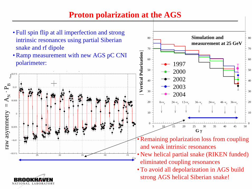
Proton polarization at the AGS
• Full spin flip at all imperfection and strong intrinsic resonances using partial Siberian snake and rf dipole
• Ramp measurement with new AGS pC CNI polarimeter:
• Remaining polarization loss from coupling and weak intrinsic resonances
• New helical partial snake (RIKEN funded) eliminated coupling resonances
• To avoid all depolarization in AGS build strong AGS helical Siberian snake!
raw
asy
mm
etry
= A
N·P
B
Simulation (2003)
G γ5 10 15 20 25 30 35 40 45 50
| Ver
tical
Pol
ariz
atio
n |
0
10
20
30
40
50
60
70
80
0
10
20
30
40
50
60
70
80
Experiment data (2000)
Simulation (2000)Experiment data (2002)
Simulation (2002)Experiment data (2003)
Simulation (2003)
19972000200220032004
24−νy 12+νy0+νy 36−νy 24+νy 48−νy 36+νy
Simulation and measurement at 25 GeV

Strong Partial Siberian Snake in AGS
partial snake resonance
Pola
riza
tion
Intrinsic resonance
Imperfection resonance
desired vertical betatron tune to avoid depolarization
Challenges:1. SC element in warm machine2. Lattice disturbances

New AGS helical snakes
2.6 m
5 % helical snake build at Tokana Industries funded by RIKEN.
• Cold strong snake eliminates all depolarizing resonances in AGS.
• Warm snake avoids polarization mismatch at AGS injection and extraction.
2.6 m
30% s.c. helical snake build at SMD (AIP)Installation: Jan. 2005
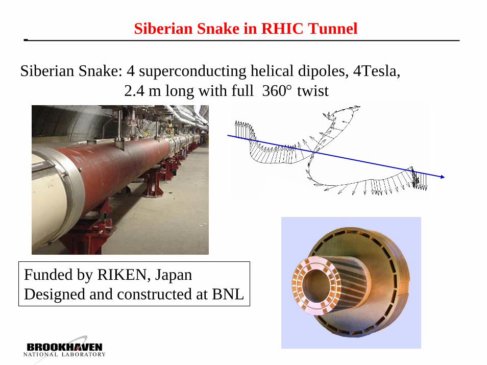
Siberian Snake in RHIC Tunnel
Siberian Snake: 4 superconducting helical dipoles, 4Tesla, 2.4 m long with full 360° twist
Funded by RIKEN, JapanDesigned and constructed at BNL
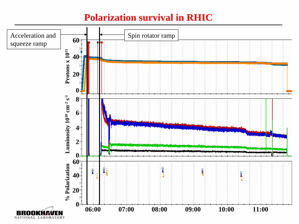
Polarization survival in RHIC
06:00 07:00 08:00 09:00 10:00 11:00
20
40
60
0
20
40
60
0
0
2
4
6
8
% P
olar
izat
ion
Lum
inos
ity 1
030cm
-2s-1
Prot
ons x
1011
Spin rotator rampAcceleration and squeeze ramp

RHIC II luminosity upgrade
Eliminate beam blow-up from intra-beam scattering with electron beam cooling at full energy!What will remain the same:
120 bunch pattern100 ns collision spacing ( ~ same data acquisition system)Only one beam collision between DX magnets
20 m magnet-free space for detectorsNo “mini-beta” quadrupoles
Approx. the same bunch intensityNo new vacuum or instability issuesBackground similar as before upgrade
What changes:Smaller transverse and longitudinal emittance
Smaller vertex regionBeta squeeze during store to level luminosityStore length is limited to ~ 5 hours by “burn-off” due to Au-Au interactions (~ 200 b)
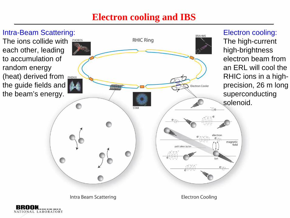
Electron cooling and IBSIntra-Beam Scattering:The ions collide with each other, leadingto accumulation of random energy(heat) derived from the guide fields and the beam’s energy.
Electron cooling:The high-current high-brightness electron beam from an ERL will cool the RHIC ions in a high-precision, 26 m long superconducting solenoid.

RHIC electron cooling
Au ions in RHIC are 100 times more energetic than in a typical cooler ring. Relativistic factors slow the cooling by a factor of γ2. Cooling power needs to be a factor of γ2 higher than typical.
Bunched electron beam requirements for 100 GeV/u gold beams: E = 54 MeV, <I> ~ 100 mA, electron beam power: ~ 5 MW!
Requires high brightness, high power, energy recovering superconducting linac, as demonstrated by JLab for IR FEL. (50 MeV, 5 mA)
First linac based, bunched electron beam cooling system used at a collider
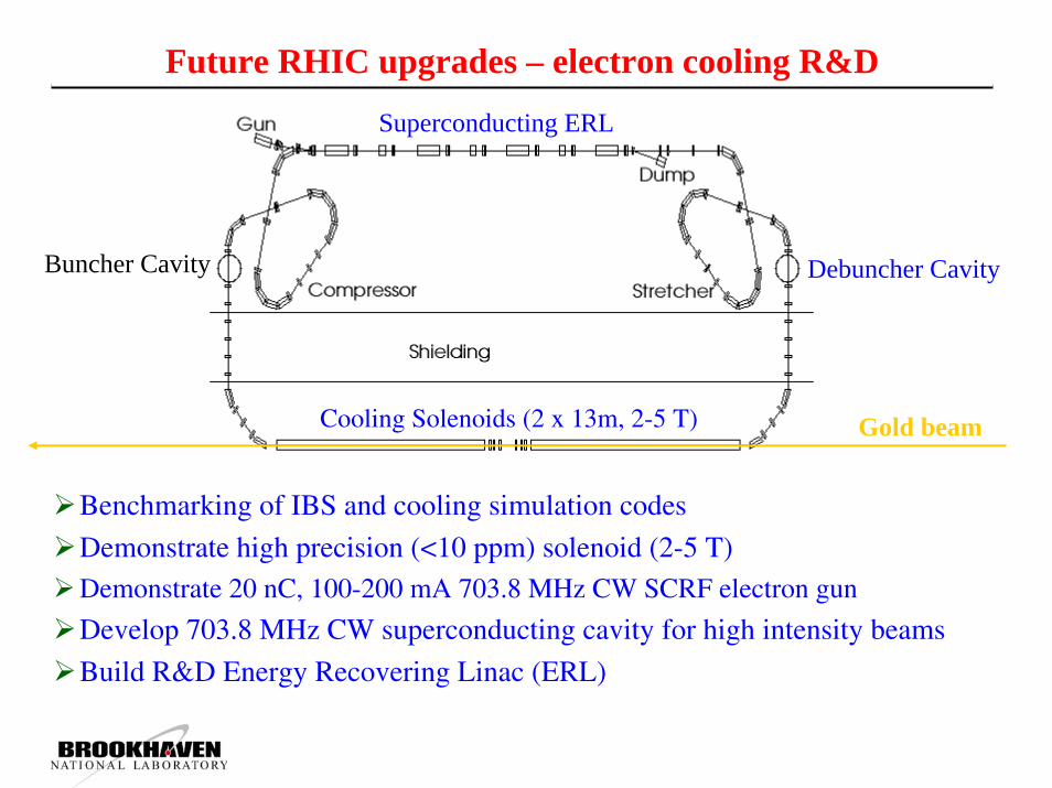
Future RHIC upgrades – electron cooling R&D
Superconducting ERL
Buncher Cavity
Cooling Solenoids (2 x 13m, 2-5 T)
Debuncher Cavity
Gold beam
Benchmarking of IBS and cooling simulation codes
Demonstrate high precision (<10 ppm) solenoid (2-5 T)Demonstrate 20 nC, 100-200 mA 703.8 MHz CW SCRF electron gun
Develop 703.8 MHz CW superconducting cavity for high intensity beams
Build R&D Energy Recovering Linac (ERL)
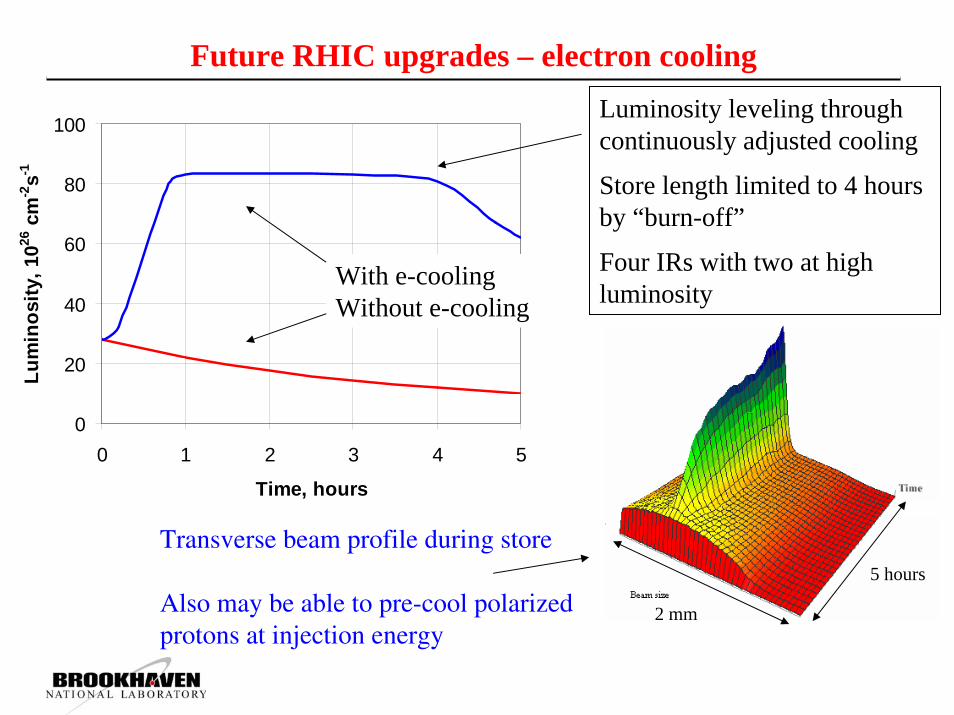
RHIC Luminosity with and without CoolingFuture RHIC upgrades – electron cooling
0
20
40
60
80
100
0 1 2 3 4 5
Time, hours
Lum
inos
ity, 1
026 c
m-2
s-1
With e-coolingWithout e-cooling
Luminosity leveling through continuously adjusted cooling
Store length limited to 4 hours by “burn-off”
Four IRs with two at high luminosity
2 mm
5 hours
Transverse beam profile during store
Also may be able to pre-cool polarized protons at injection energy

RHIC II Luminosities with Electron Cooling
Gold collisions (100 GeV/n x 100 GeV/n): w/o e-cooling with e-coolingEmittance (95%) πµm 15 → 40 15 → 3Beta function at IR [m] 1.0 1.0 → 0.5Number of bunches 112 112Bunch population [109] 1 1 → 0.3Beam-beam parameter per IR 0.0016 0.004Ave. store luminosity [1026 cm-2 s-1] 8 70
Pol. Proton Collision (250 GeV x 250 GeV):Emittance (95%) πµm 20 12Beta function at IR [m] 1.0 0.5Number of bunches 112 112Bunch population [1011] 2 2Beam-beam parameter per IR 0.007 0.012 ?Ave. store luminosity [1032 cm-2 s-1] 1.5 5.0
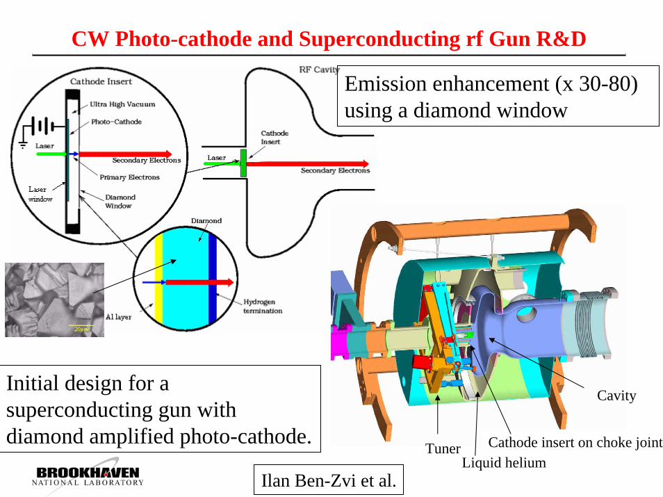
CW Photo-cathode and Superconducting rf Gun R&D
Emission enhancement (x 30-80) using a diamond window
Initial design for a superconducting gun with diamond amplified photo-cathode.
Cavity
Tuner Cathode insert on choke jointLiquid helium
Ilan Ben-Zvi et al.

703.8 MHz CW Superconducting Cavity for High Intensity Beams
2K main line
Inner magnetic shield
Large bore cavity
4” RF shieldedgate valve
2K fill line
He vessel
Vacuum vessel
Fundamental PowerCoupler assembly
HOM ferritedampers
Outer magnetic shield
Thermal shield
Tuner location Space framesupport structure
Vacuum vessel
Cold model tested successfully

Solenoid R&D: <10 ppm Directional Uniformity
Copper Solenoid18 mT; 1.83 m longDipole Corrector
LASER
BEAMSPLITTER
MAGNETICNEEDLE
MIRROR
OPTICALFILTER
POSITION SENSITIVE DETECTOR
5 T design started

Electron-Ion Collider at RHIC: eRHIC• 10 GeV, 0.5 A e-ring with ¼ of RHIC circumference (similar to PEP II HER)• 10 GeV electron beam → s1/2 for e-A : 63 GeV/u; s1/2 for e↑-p↑: 100 GeV• Existing RHIC interaction region allows for typical asymmetric detector• Luminosity: up to 1 × 1033 cm−2s−1 per nucleon
BNL, MIT Batescollaboration
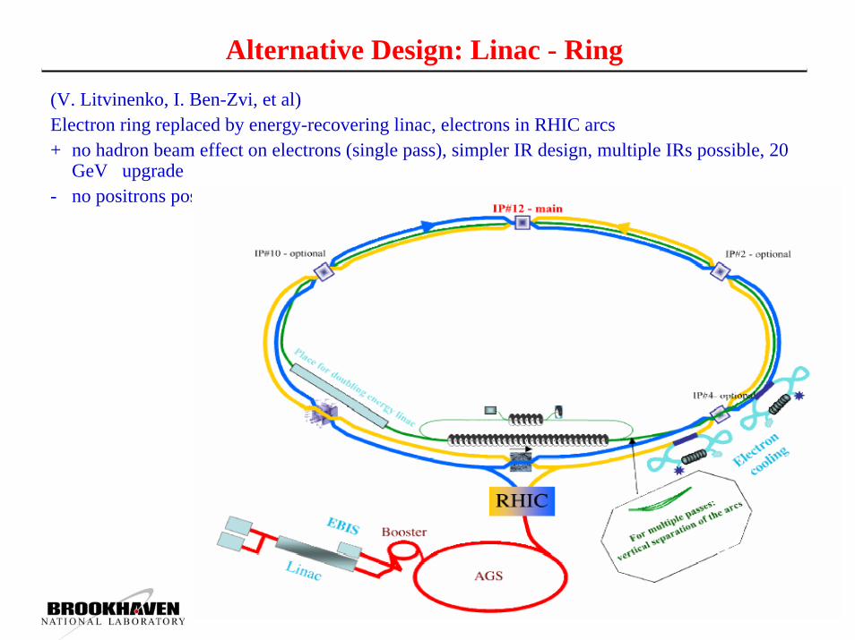
Alternative Design: Linac - Ring(V. Litvinenko, I. Ben-Zvi, et al)Electron ring replaced by energy-recovering linac, electrons in RHIC arcs+ no hadron beam effect on electrons (single pass), simpler IR design, multiple IRs possible, 20
GeV upgrade- no positrons possible, cost
Summary
Since 2000 RHIC has collided, for the first time,Heavy ionsLight on heavy ionsPolarized protons (45% beam polarization)
Heavy ion luminosity increased by factor 100For next 4 years planned:
Factor 2 increase in heavy ion luminosityFactor 2 increase in proton beam polarizationFactor 40 increase in proton luminosity
Future upgrades:RHIC luminosity upgrade using electron cooling at storeElectron-ion collider eRHIC


