

P.O. Box 1871 Plot # 598-1152Dubai Investment Park - Dubai, UAE
Tel. # 04 810-5105Fax. # 04 810-5106
Email: [email protected]: www.faisaljassim.ae
FAISAL JASSIM INDUSTRIES (L.L.C.)
ROUND PRESSURE INDEPENDENT TERMINAL UNITS
GHD
RPITU Round Pressure Independent Terminal Units

GHD-1
ROUND PRESSUREINDEPENDENT TERMINAL UNITS
Material Specifications subject to change as per customer’s demand.
Model RPITU
• Casing 0.9mm (21 gauge) galvanized steel sheet.• Blades are double-skin 0.9mm thick (21 gauge) galvanized steel sheet each• Bearing - Brass Bush 12mm Round• Aluminum Flow Grid.
Powder coating available as optional.
MATERIAL SPECIFICATIONS
• Circular damper blade for better ow management• EDPM gasket on damper blade for low leakage.• Multi-point averaging inlet differential pressure sensor•• Shaft indicator for damper position.• Control components encased in control panel (optional).
Features:
Terminal units also incorporate control compo-nents (VAV actuator, transformer) which are fac-tory tted and calibrated in our in house calibra-tion rig to ensure all RPITU meet the design crite-ria of our customer. This enables the terminal to monitor desired air ow rate as dictated by the thermostat or input signal of 0-10V and compensate instantly for any changes in supply air pres-sure that might tend to alter the supply air volume. Net resultant is a pressure independent variable air volume system.
The complete VAV terminal/silencer assembly has been tested in accordance to AHRI 880.
ROUND PRESSURE INDEPENDENT TERMINAL UNIT
Flow Tech pressure independent terminal units are designed to control air volume ow rate for supply air on variable volume system. These units are designed to supply the air ow rate of condi-tioned air into an occupied zone in response to control signal from a thermostat or building man-agement system. These could also be used as stand alone system.stand alone system.
Flow Tech Terminal units consist of a casing with circular inlet spigot and integral 900mm longattenuator. Circular damper blade and cross ow differential pressure sensor for measuring air volume. The casing design and optimized silencer geometry reduce self-generated noise and mini-mize pressure drop.
Model RPITU

GHD-2
ROUND PRESSUREINDEPENDENT TERMINAL UNITS
DIMENSIONS
Right hand control panel as Standard, Left hand control panel available as optional.
D
400
450
500
550
500
600
650
750
250
250
250
250
250
250
300
300
300
300
300
300
300250900
MODEL
RPITU 15
RPITU 20
RPITU 25
RPITU 30
RPITU 35
RPITU 40
RPITU 50
C L F G
Figure 2
(Sound Attenuator)(VAV)
FIG. 2: VAV TERMINAL UNITS WITH SOUND ATTENUATOR - RPITU-SA
Figure 1
FIG.1: VAV TERMINAL UNITS MODEL - RPITU

GHD-3
ROUND PRESSURE INDEPENDENT TERMINAL UNITS
Selection Guide
1. Units obtained in ac cordance with AHRI Standard 880-2011 and ASHRAE Standard 130-1996.2. Airow is given in Litres/Second, L/S and Cubic Feet/minute, CFM.3. Blank spaces indicate NC’s less than 20. X- Indicates Pressure Drop at attenuator more than 65Pa.4.4. ΔPs is the difference in static pressure from inlet to discharge of the unit.5. ΔPt is the difference in total pressure from inlet to discharge of the unit.6. Pressure is given in Pascals, Pa and Inches of Water Gauge, in.wg.7. NC values are calculated based on typical attenuation values in Appendix E, AHRI Standard 885-2008, “A Procedure for Estimating Occupied Space Sound Levels in the Application of Air Terminals and Air Outlets”. The following chart shows the attenuation deductions that have been used for NC calculations.8. ΔPs for terminal units with electric coil is equal to basic unit. Resistance of the coil elements is negligible.
Radiated Sound is based on a 5/8” mineral ber tile ceiling per AHRI 885-2008 typical attenuation values:
Discharge Sound is based on environmental effect, end reection, ex duct effect, space effect, sound power division and lined duct effect.
PERFORMANCE NOTES
TYPICAL SELECTION GUIDE

GHD-4
ROUND PRESSUREINDEPENDENT TERMINAL UNITS
NC levels presented in the Typical Selection Guide are based on typical attenuation values as outlined in AHRI standard 885-2008, Appendix E. AHRI Standard 885-2008, Appendix E provides typical sound attenuation values for air terminal discharge sound and air terminal radiated sound. The typical attenuation values are recommended for use by manufacturers to estimate application sound levels.
In product catalogs the end use environments are not known and the factors presented in AHRI Standard 885 - 2008 are provided as typical attenuation values. Use of these values will allow better comparison between manufacturers and give the provided as typical attenuation values. Use of these values will allow better comparison between manufacturers and give the end user a value which will be expected to be applicable for many types of spaces.
Following is a detailed description of the typical attenuation values used to determine NC levels.
The typical radiated sound attenuation values for three types of ceilings: TYPE 1 - Glass Fiber; TYPE 2 - Mineral Fiber; TYPE 3 - Solid Gypsum Board.
Since Mineral Fiber tile ceilings are the most common construction used in commercial buildings, the attenua-tion values in the Typical Selection Guide are based on Type 2 - Mineral Fiber.
The table on the right provides the calculation method for the radiated sound total attenuation values based on AHRI Standard 885-2008.
Radiated Sound
For a complete explanation of the attenuation factors and the procedures for calculating room NC levels, please refer to AHRI Standard 885-2008.
The ceiling/space effect assumes the following conditions:1. 5/8” tile, 20lb/ft3 density2. The plenum is at least 3 feet deep3. The plenum space is either wide (over 25ft) or lined with insulation4. The ceiling has no signicant penetration directly under the unit.
Discharge Sound
Octave Band Mid Frequency, HZ.
Environmental EffectCeiling / Space EffectTotal Attenuation Deduction
Large Box(>800 CFM)Environmental Effect5 ft (1.5m) Duct LiningEnd Reflection5 ft (1.5m), 8in(200mm) Flex DuctSpace EffectSpace EffectSound Power DivisionTotal Attenuation Deduction
Medium Box(400 - 800 CFM)Environmental Effect5 ft (1.5m) Duct LiningEnd Reflection5 ft (1.5m), 8in(200mm) Flex DuctSpace EffectSpace EffectSound Power DivisionTotal Attenuation Deduction
Small Box(<400 CFM)Environmental Effect5 ft (1.5m) Duct LiningEnd Reflection5 ft (1.5m), 8in(200mm) Flex DuctSpace EffectSpace EffectSound Power DivisionTotal Attenuation Deduction
Octave Band Mid Frequency, HZ.
Octave Band Mid Frequency, HZ.
Octave Band Mid Frequency, HZ.
TYPICAL SELECTION GUIDE

GHD-5
ROUND PRESSUREINDEPENDENT TERMINAL UNITS
1. Data obtained in accordance with AHRI Standard 880-2011 and ASHRAE Standard 130-1996.2. Airow is given in litres per second. L/S; and cubic feet per minute, CFM.3. Pressure is given in Pascals, Pa; and inches of water gauge, in.wg.4. Blank spaces indicate sound power levels less than 20.
Performance Notes:
RPITU-50
RPITU-40
RPITU-35
RPITU-30
RPITU-25
RPITU-20
RPITU-15
750 Pa (3.0” W.G)Octave Band
500 Pa (2.0” W.G)Octave Band
250 Pa (1.0” W.G)Octave Band
-12Sound Power Levels, LW dB, re 10 Watts
125 Pa (0.5” W.G)Octave Band
AirflowCFM L/S
Model
DISCHARGE SOUND POWER LEVELS

GHD-6
ROUND PRESSUREINDEPENDENT TERMINAL UNITS
1. Data obtained in accordance with AHRI Standard 880-2011 and ASHRAE Standard 130-1996.2. Airow is given in litres per second. L/S; and cubic feet per minute, CFM.3. Pressure is given in Pascals, Pa; and inches of water gauge, in.wg.4. Blank spaces indicate sound power levels less than 20.
Performance Notes:
RPITU-50
RPITU-40
RPITU-35
RPITU-30
RPITU-25
RPITU-20
RPITU-15
750 Pa (3.0” W.G)Octave Band
500 Pa (2.0” W.G)Octave Band
250 Pa (1.0” W.G)Octave Band
-12Sound Power Levels, LW dB, re 10 Watts
125 Pa (0.5” W.G)Octave Band
AirflowCFM L/S
Model
RADIATED SOUND POWER LEVELS

GHD-7
ROUND PRESSUREINDEPENDENT TERMINAL UNITS
1. Data obtained in accordance with AHRI Standard 880-2011 and ASHRAE Standard 130-1996.2. Airow is given in litres per second. L/S; and cubic feet per minute, CFM.3. Pressure is given in Pascals, Pa; and inches of water gauge, in.wg.4. Blank spaces indicate sound power levels less than 20.
Performance Notes:
RPITU-SA50
RPITU-SA40
RPITU-SA35
RPITU-SA30
RPITU-SA25
RPITU-SA20
RPITU-SA15
750 Pa (3.0” W.G)Octave Band
500 Pa (2.0” W.G)Octave Band
250 Pa (1.0” W.G)Octave Band
-12Sound Power Levels, LW dB, re 10 Watts
125 Pa (0.5” W.G)Octave Band
AirflowCFM L/S
Model
DISCHARGE SOUND POWER LEVELS WITH SOUND ATTENUATORS
GHD-8
ROUND PRESSUREINDEPENDENT TERMINAL UNITS
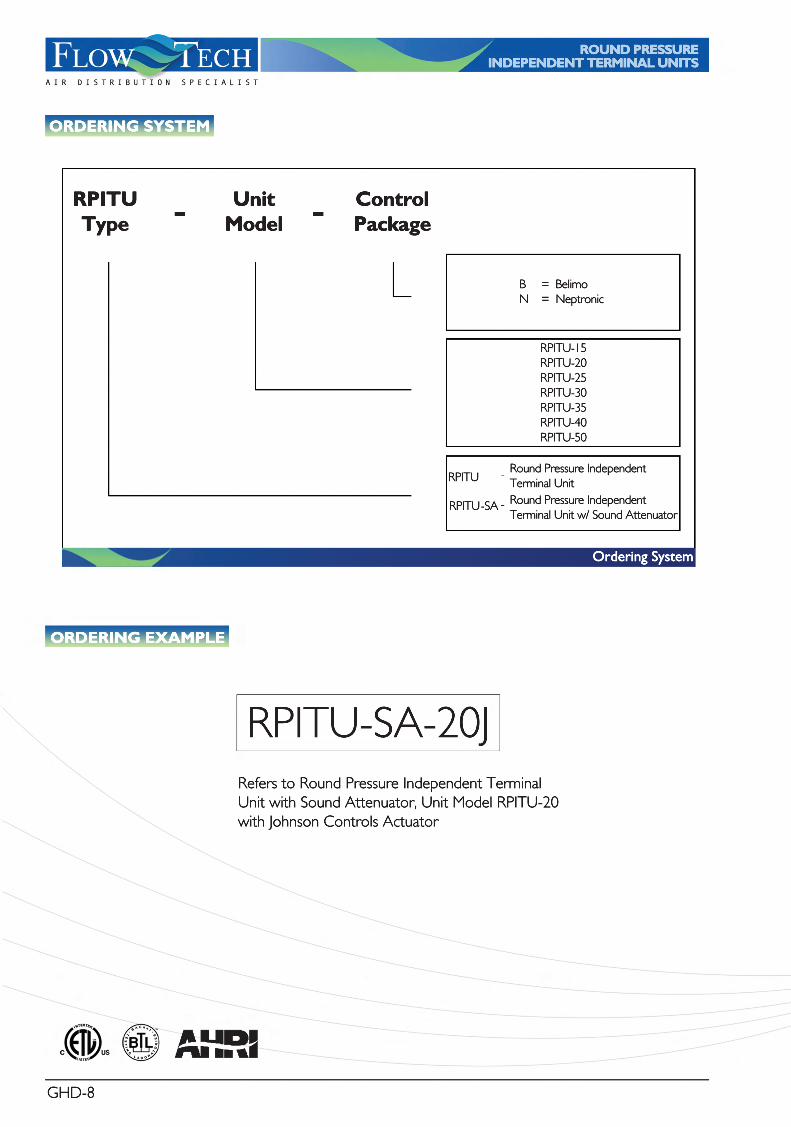
Refers to Round Pressure Independent TerminalUnit with Sound Attenuator, Unit Model RPITU-20with Johnson Controls Actuator
RPITU-SA-20J
ORDERING EXAMPLE
UnitModel
RPITUType - -Control
Package
RPITU
RPITU -SA Round Pressure Independent Terminal Unit w/ Sound Attenuator
Round Pressure Independent Terminal Unit -
-
B = BelimoN = Neptronic
RPITU-15RPITU-20RPITU-25RPITU-30RPITU-35RPITU-40RPITU-50RPITU-50
Ordering System
ORDERING SYSTEM


