

RT12/RT16/RT20/RT24 Operator’s Manual Overview - 1
CMW
Overview
Chapter Contents
Serial Number Location . . . . . . . . . . . . . . . . . . . . . . 2
Intended Use . . . . . . . . . . . . . . . . . . . . . . . . . . . . . . . 3
Equipment Modification . . . . . . . . . . . . . . . . . . . . . . 3
Unit Components . . . . . . . . . . . . . . . . . . . . . . . . . . . 3
Operator Orientation. . . . . . . . . . . . . . . . . . . . . . . . . 4
About This Manual . . . . . . . . . . . . . . . . . . . . . . . . . . 4
• Bulleted Lists. . . . . . . . . . . . . . . . . . . . . . . . . . . . . . . . . . . . . . . . . . . . . . 4
• Numbered Lists . . . . . . . . . . . . . . . . . . . . . . . . . . . . . . . . . . . . . . . . . . . . 4
Overview - 2 RT12/RT16/RT20/RT24 Operator’s ManualSerial Number Location
CMW
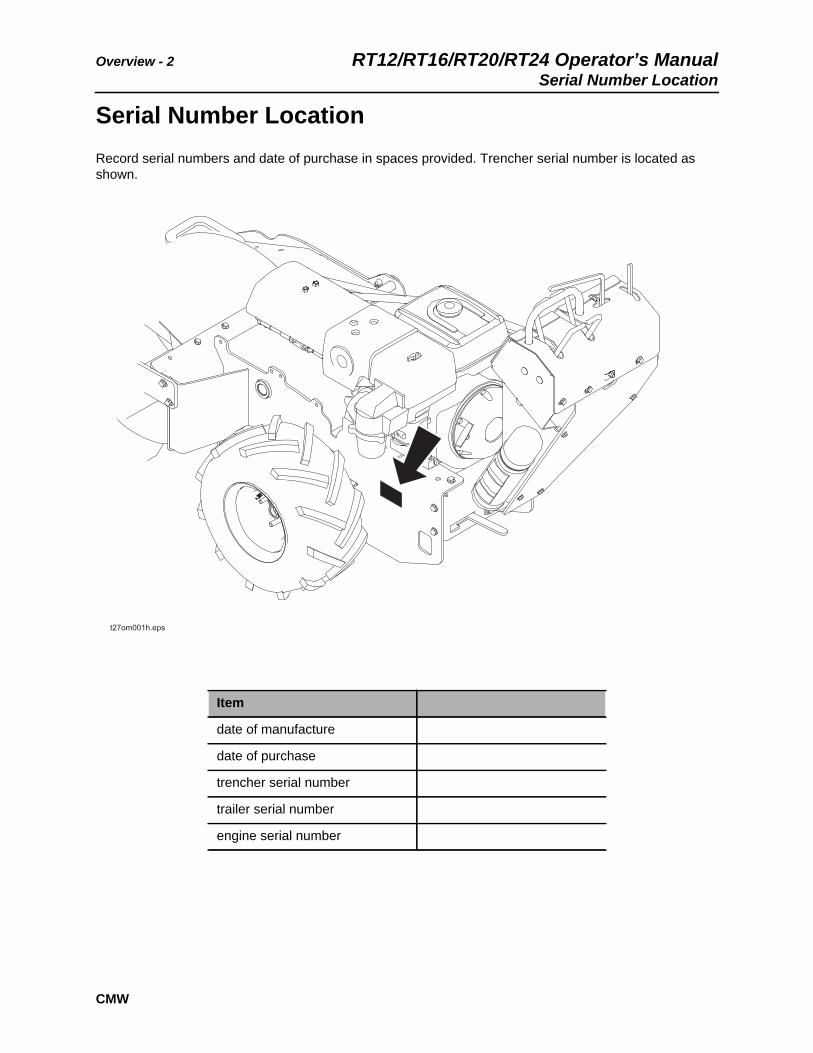
Serial Number LocationRecord serial numbers and date of purchase in spaces provided. Trencher serial number is located as shown.
Item
date of manufacture
date of purchase
trencher serial number
trailer serial number
engine serial number

RT12/RT16/RT20/RT24 Operator’s Manual Overview - 3Intended Use
CMW
Intended UseThe RT12, RT16, RT20, and RT24 pedestrian trenchers are designed to install buried cable and pipe to depths of 48” (1220 mm) and widths of 8” (200 mm). These units are intended for operation in ambient temperatures from 20° to 115°F (-7° to 46°C). Use in any other way is considered contrary to the intended use.
RT12, RT16, RT20, and RT24 units should be used with genuine Ditch Witch chain, teeth, and sprockets. They should be operated, serviced, and repaired only by persons familiar with their particular characteristics and acquainted with the relevant safety procedures.
Equipment ModificationThis equipment was designed and built in accordance with applicable standards and regulations. Modification of equipment could mean that it will no longer meet regulations and may not function properly or in accordance with the operating instructions. Modification of equipment should only be made by competent personnel possessing knowledge of applicable standards, regulations, equipment design functionality/requirements and any required specialized testing.
Unit Components
1. Control console
2. Engine
3. Digging boom and chain
4. Trail wheel
Overview - 4 RT12/RT16/RT20/RT24 Operator’s ManualOperator Orientation
CMW
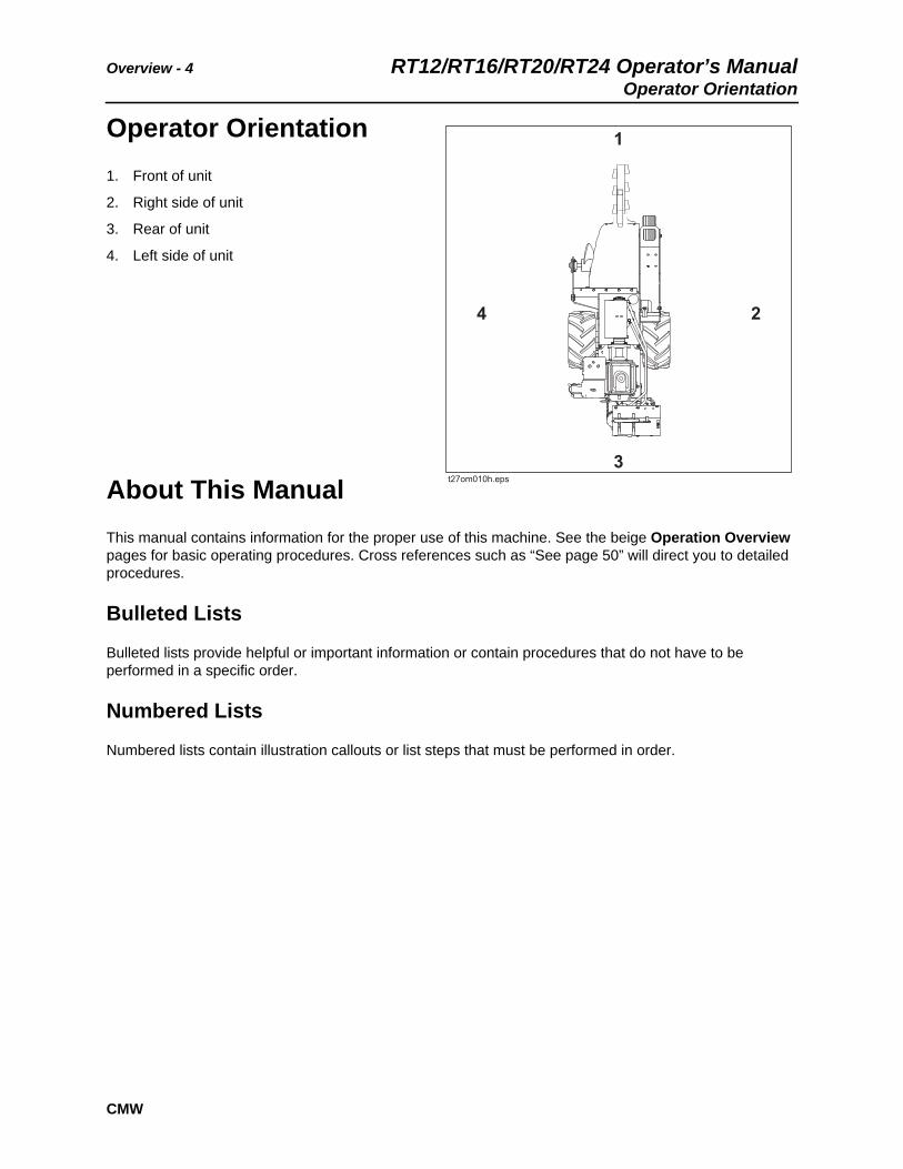
Operator Orientation1. Front of unit
2. Right side of unit
3. Rear of unit
4. Left side of unit
About This ManualThis manual contains information for the proper use of this machine. See the beige Operation Overview pages for basic operating procedures. Cross references such as “See page 50” will direct you to detailed procedures.
Bulleted Lists
Bulleted lists provide helpful or important information or contain procedures that do not have to be performed in a specific order.
Numbered Lists
Numbered lists contain illustration callouts or list steps that must be performed in order.
RT12/RT16/RT20/RT24 Operator’s Manual Foreword - 5
CMW
Foreword
This manual is an important part of your equipment. It provides safety information and operation instructions to help you use and maintain your Ditch Witch equipment.
Read this manual before using your equipment. Keep it with the equipment at all times for future reference. If you sell your equipment, be sure to give this manual to the new owner.
If you need a replacement copy, contact your Ditch Witch dealer. If you need assistance in locating a dealer, visit our website at www.ditchwitch.com or write to the following address:
The Charles Machine Works, Inc.Attn: Marketing DepartmentPO Box 66Perry, OK 73077-0066 USA
The descriptions and specifications in this manual are subject to change without notice. The Charles Machine Works, Inc. reserves the right to improve equipment. Some product improvements may have taken place after this manual was published. For the latest information on Ditch Witch equipment, see your Ditch Witch dealer.
Thank you for buying and using Ditch Witch equipment.

Foreword - 6 RT12/RT16/RT20/RT24 Operator’s Manual
CMW
RT12/RT16/RT20/RT24 Operator’s Manual
Issue number 1.0/OM-12/11Part number 053-2439
Copyright 2011by The Charles Machine Works, Inc.
, Ditch Witch, CMW, and Roto Witch are registered trademarks of The Charles Machine Works, Inc.

RT12/RT16/RT20/RT24 Operator’s Manual Contents - 7
CMW
Contents
Overviewmachine serial number, information about the type of work this machine is designed to perform, basic machine components, and how to use this manual
1
Forewordpart number, revision level, and publication date of this manual, and factory contact information
5
Safetymachine safety alerts and emergency procedures
9
Controlsmachine controls, gauges, and indicators and how to use them
21
Prepareprocedures for inspecting and classifying the jobsite, planning the installation path, and preparing the jobsite for work
31
Driveprocedures for startup, cold start, driving, and shutdown
37
Transportprocedures for lifting, hauling, and towing
41
Trenchprocedures for trenching
49
Drillprocedures for drilling
53
Systems and Equipmentchain, teeth, sprockets, and optional equipment
61
Complete the Jobprocedures for backfilling and restoring the jobsite and rinsing and storing equipment
69
Serviceservice intervals and instructions for this machine including lubrication, replacement of wear items, and basic maintenance
71
Contents - 8 RT12/RT16/RT20/RT24 Operator’s Manual
CMW
Specificationsmachine specifications including weights, measurements, power ratings, and fluid capacities
95
Supportthe warranty policy for this machine, and procedures for obtaining warranty consideration and training
109
Service Recorda record of major service performed on the machine
113
RT12/RT16/RT20/RT24 Operator’s Manual Safety - 9
CMW
Safety
Chapter Contents
Guidelines . . . . . . . . . . . . . . . . . . . . . . . . . . . . . . . . 10
Safety Alert Classifications . . . . . . . . . . . . . . . . . . 11
Safety Alerts . . . . . . . . . . . . . . . . . . . . . . . . . . . . . . 12
Emergency Procedures . . . . . . . . . . . . . . . . . . . . . 15
• Electric Strike Description . . . . . . . . . . . . . . . . . . . . . . . . . . . . . . . . . . . 15
• If an Electric Line is Damaged . . . . . . . . . . . . . . . . . . . . . . . . . . . . . . . 16
• If a Gas Line is Damaged . . . . . . . . . . . . . . . . . . . . . . . . . . . . . . . . . . . 16
• If a Fiber Optic Cable is Damaged . . . . . . . . . . . . . . . . . . . . . . . . . . . . 17
• If Machine Catches on Fire . . . . . . . . . . . . . . . . . . . . . . . . . . . . . . . . . . 17

Safety - 10 RT12/RT16/RT20/RT24 Operator’s ManualGuidelines
CMW
GuidelinesFollow these guidelines before operating any jobsite equipment:
• Complete proper training and read operator’s manual before using equipment.
• Contact your local One-Call (811 in USA) or the One-Call referral number (888-258-0808 in USA and Canada) to have underground utilities located before digging. Also contact any utilities that do not participate in the One-Call service.
• Classify jobsite based on its hazards and use correct tools and machinery, safety equipment, and work methods for jobsite.
• Mark jobsite clearly and keep spectators away.
• Wear personal protective equipment.
• Review jobsite hazards, safety and emergency procedures, and individual responsibilities with all personnel before work begins. Safety videos are available from your Ditch Witch dealer.
• Replace missing or damaged safety shields and safety signs.
• Use equipment carefully. Stop operation and investigate anything that does not look or feel right.
• Do not operate unit where flammable gas may be present.
• Contact your Ditch Witch dealer if you have any question about operation, maintenance, or equipment use.
RT12/RT16/RT20/RT24 Operator’s Manual Safety - 11Safety Alert Classifications
CMW
Safety Alert ClassificationsThese classifications and the icons defined on the following pages work together to alert you to situations which could be harmful to you, jobsite bystanders or your equipment. When you see these words and icons in the book or on the machine, carefully read and follow all instructions. YOUR SAFETY IS AT STAKE.
Watch for the three safety alert levels: DANGER, WARNING and CAUTION. Learn what each level means.
indicates a hazardous situation that, if not avoided, will result in death or serious injury. This signal word is to be limited to the most extreme situations.
indicates a hazardous situation that, if not avoided, could result in death or serious injury.
indicates a hazardous situation that, if not avoided, could result in minor or moderate injury.
Watch for two other words: NOTICE and IMPORTANT.
NOTICE indicates information considered important, but not hazard-related (e.g., messages relating to property damage).
IMPORTANT can help you do a better job or make your job easier in some way.

Safety - 12 RT12/RT16/RT20/RT24 Operator’s ManualSafety Alerts
CMW
Safety Alerts
Moving digging teeth will kill you or cut off arm or leg. Stay away.
Turning shaft will kill you or crush arm or leg. Stay away.
Electric shock. Contacting electric lines will cause death or serious injury. Know location of lines and stay away.
Deadly gases. Lack of oxygen or presence of gas will cause sickness or death. Provide ventilation.
Jobsite hazards could cause death or serious injury. Use correct equipment and work methods. Use and maintain proper safety equipment.
Crushing weight could cause death or serious injury. Use proper procedures and equipment or stay away.
Moving parts could cut off hand or foot. Stay away.

RT12/RT16/RT20/RT24 Operator’s Manual Safety - 13Safety Alerts
CMW
Explosion possible. Serious injury or equipment damage could occur. Follow directions carefully.
Incorrect procedures could result in death, injury, or property damage. Learn to use equipment correctly.
Improper control function could cause death or serious injury. If control does not work as described in instructions, stop machine and have it serviced.
Looking into fiber optic cable could result in permanent vision damage. Do not look into ends of fiber optic or unidentified cable.
Pressurized fluid or air could pierce skin and cause injury or death. Stay away.
Fire or explosion possible. Fumes could ignite and cause burns. No smoking, no flame, no spark.
Moving traffic - hazardous situation. Death or serious injury could result. Avoid moving vehicles, wear high visibility clothing, post appropriate warning signs.

Safety - 14 RT12/RT16/RT20/RT24 Operator’s ManualSafety Alerts
CMW
Hot pressurized cooling system fluid could cause serious burns. Allow to cool before servicing.
Flying objects may cause injury. Wear hard hat and safety glasses.
Hot parts may cause burns. Do not touch until cool.
Exposure to high noise levels may cause hearing loss. Wear hearing protection.
Fall possible. Slips or trips may result in injury. Keep area clean.
Battery acid may cause burns. Avoid contact.
Improper handling or use of chemicals may result in illness, injury, or equipment damage. Follow instructions on labels and in material safety data sheets (MSDS).

RT12/RT16/RT20/RT24 Operator’s Manual Safety - 15Emergency Procedures
CMW
Emergency Procedures
Before operating any equipment, review emergency procedures and check that all safety precautions have been taken.
Electric Strike Description
When working near electric cables, remember the following:
• Electricity follows all paths to ground, not just path of least resistance.
• Pipes, hoses, and cables will conduct electricity back to all equipment.
• Low voltage current can injure or kill. Many work-related electrocutions result from contact with less than 440 volts.
Most electric strikes are not noticeable, but indications of a strike include:
• power outage
• smoke
• explosion
• popping noises
• arcing electricity
If any of these occur, assume an electric strike has occurred.
Jobsite hazards could cause death or serious injury. Use correct equipment and work methods. Use and maintain proper safety equipment.
EMERGENCY SHUTDOWN - Release all controls and turn ignition switch to STOP.
Electric shock. Contacting electric lines will cause death or serious injury. Know location of lines and stay away.
Safety - 16 RT12/RT16/RT20/RT24 Operator’s ManualEmergency Procedures
CMW
If an Electric Line is Damaged
If you suspect an electric line has been damaged and you are near pedestrian unit, DO NOT MOVE and do not touch unit. Take the following actions. The order and degree of action will depend upon the situation.
• Warn people nearby that an electric strike has occurred. Instruct them to leave the area and contact utility.
• Do not allow anyone into area until given permission by utility company.
• Do not allow anyone to touch equipment.
If a Gas Line is Damaged
If you suspect a gas line has been damaged, take the following actions. The order and degree of action will depend on the situation.
• Immediately shut off engine(s), if this can be done safely and quickly.
• Remove any ignition source(s), if this can be done safely and quickly.
• Warn others that a gas line has been cut and that they should leave the area.
• Leave jobsite as quickly as possible.
• Immediately call your local emergency phone number and utility company.
• If jobsite is along street, stop traffic from driving near jobsite.
• Do not return to jobsite until given permission by emergency personnel and utility company.
Fire or explosion possible. Fumes could ignite and cause burns. No smoking, no flame, no spark.
Explosion possible. Serious injury or equipment damage could occur. Follow directions carefully.

RT12/RT16/RT20/RT24 Operator’s Manual Safety - 17Emergency Procedures
CMW
If a Fiber Optic Cable is Damaged
Do not look into cut ends of fiber optic or unidentified cable. Vision damage can occur.
If Machine Catches on Fire
Perform emergency shutdown procedure and then take the following actions. The order and degree of action will depend on the situation.
• Immediately move battery disconnect switch (if equipped) to disconnect position.
• If fire is small and fire extinguisher is available, attempt to extinguish fire.
• If fire cannot be extinguished, leave area as quickly as possible and contact emergency personnel.

Safety - 18 RT12/RT16/RT20/RT24 Operator’s ManualEmergency Procedures
CMW

RT12/RT16/RT20/RT24 Operator’s Manual Operation Overview - 19
CMW
Operation Overview
Chapter Contents
Planning. . . . . . . . . . . . . . . . . . . . . . . . . . . . . . . . . . 20
Trenching. . . . . . . . . . . . . . . . . . . . . . . . . . . . . . . . . 20
Leaving Jobsite. . . . . . . . . . . . . . . . . . . . . . . . . . . . 20

Operation Overview - 20 RT12/RT16/RT20/RT24 Operator’s ManualPlanning
CMW
Planning1. Gather information about jobsite. See page 31.
2. Inspect jobsite. See page 33.
3. Classify jobsite. See page 34.
4. Select best chain type and tooth pattern for your application. See page 62.
5. Consider optional equipment, if necessary. See page 64.
6. Check supplies and prepare equipment. See page 36.
7. Load unit onto trailer. See page 43.
Trenching1. Unload unit from trailer. See page 46.
2. Leave optional backfill blade, if equipped, in stowed position with digging boom low to ground.
3. Start unit. See page 38.
4. Drive to starting point of trench. See page 39.
5. Dig the trench. See page 51.
6. Shut down unit. See page 39.
Leaving Jobsite1. Restore the jobsite. See page 70.
2. Rinse unit and stow tools. See page 70.
3. Load unit onto trailer. See page 43.
RT12/RT16/RT20/RT24 Operator’s Manual Controls - 21
CMW
Controls
Chapter Contents
Control Console . . . . . . . . . . . . . . . . . . . . . . . . . . . 22
RT12 Engine Controls . . . . . . . . . . . . . . . . . . . . . . 26
RT16 Engine Controls . . . . . . . . . . . . . . . . . . . . . . 27
RT20 and RT24 Engine Controls . . . . . . . . . . . . . . 29

Controls - 22 RT12/RT16/RT20/RT24 Operator’s ManualControl Console
CMW
Control Console
1. Digging chain/Roto Witch® control
2. Selector valve control (Roto Witch® option)
3. Boom lift control
4. Speed/direction controls
5. Parking brake lever
6. Hourmeter/tachometer (RT16 option)
6B. Hourmeter (RT 12 option)
7. Ignition Switch (RT12)
8. Throttle switch (RT12)
RT12/RT16/RT20/RT24 Operator’s Manual Controls - 23Control Console
CMW
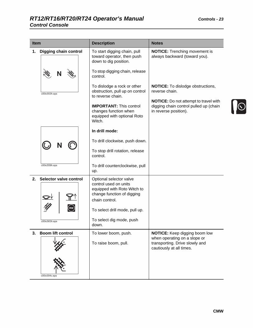
Item Description Notes
1. Digging chain control To start digging chain, pull toward operator, then push down to dig position.
To stop digging chain, release control.
To dislodge a rock or other obstruction, pull up on control to reverse chain.
IMPORTANT: This control changes function when equipped with optional Roto Witch.
In drill mode:
To drill clockwise, push down.
To stop drill rotation, release control.
To drill counterclockwise, pull up.
NOTICE: Trenching movement is always backward (toward you).
NOTICE: To dislodge obstructions, reverse chain.
NOTICE: Do not attempt to travel with digging chain control pulled up (chain in reverse position).
2. Selector valve control Optional selector valve control used on units equipped with Roto Witch to change function of digging chain control.
To select drill mode, pull up.
To select dig mode, push down.
3. Boom lift control To lower boom, push.
To raise boom, pull.
NOTICE: Keep digging boom low when operating on a slope or transporting. Drive slowly and cautiously at all times.

Controls - 24 RT12/RT16/RT20/RT24 Operator’s ManualControl Console
CMW
4. Speed/direction controls
To drive straight forward, push BOTH controls slowly forward.
To drive straight in reverse, pull BOTH controls slowly rearward.
To turn left, move RIGHT speed/direction control for forward or reverse.
To turn right, move LEFT speed/direction control for forward or reverse.
To go faster in any direction, move controls farther from neutral position.
To stop, release controls.
NOTICE: Trenching movement is always backward (toward you).
5. Parking brake To engage parking brake, move lever to the right.
To disengage parking brake, move lever left to notch.
IMPORTANT:
• Move unit slightly to ensure parking brake pins are engaged.
• It might be necessary to move unit slightly to disengage parking brake.
Item Description Notes
RT12/RT16/RT20/RT24 Operator’s Manual Controls - 25Control Console
CMW
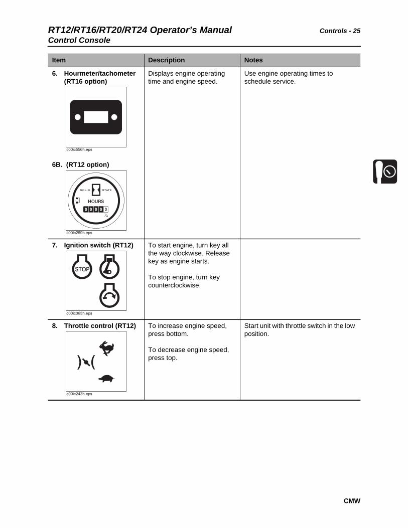
6. Hourmeter/tachometer (RT16 option)
6B. (RT12 option)
Displays engine operating time and engine speed.
Use engine operating times to schedule service.
7. Ignition switch (RT12) To start engine, turn key all the way clockwise. Release key as engine starts.
To stop engine, turn key counterclockwise.
8. Throttle control (RT12) To increase engine speed, press bottom.
To decrease engine speed, press top.
Start unit with throttle switch in the low position.
Item Description Notes
c00ic259h.eps
c00ic243h.eps

Controls - 26 RT12/RT16/RT20/RT24 Operator’s ManualRT12 Engine Controls
CMW
RT12 Engine Controls
1. Fuel shut-off valve
Item Description Notes
1. Fuel shut-off valve To stop fuel flow from fuel tank to engine, slide lever away from engine.
To allow fuel flow, slide lever toward engine.
Close valve when transporting unit to or from jobsite, or whenever machine is parked.
1
t27om070h.eps
RT12/RT16/RT20/RT24 Operator’s Manual Controls - 27RT16 Engine Controls
CMW
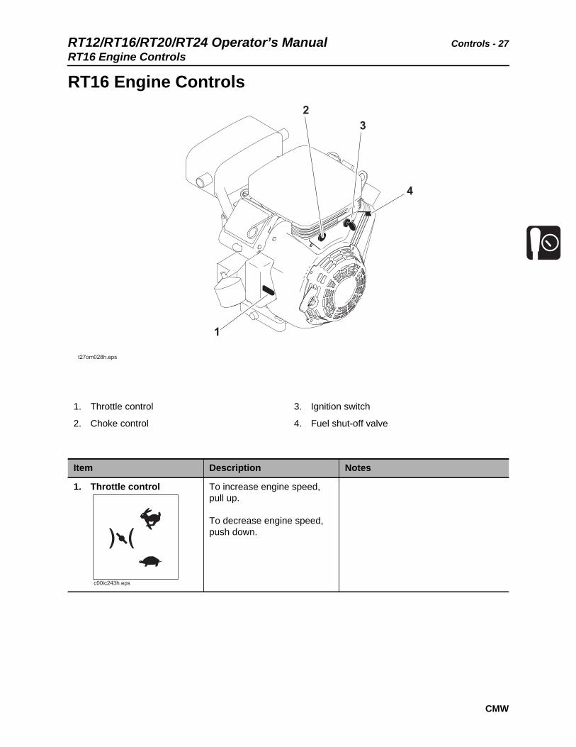
RT16 Engine Controls
1. Throttle control
2. Choke control
3. Ignition switch
4. Fuel shut-off valve
Item Description Notes
1. Throttle control To increase engine speed, pull up.
To decrease engine speed, push down.
c00ic243h.eps

Controls - 28 RT12/RT16/RT20/RT24 Operator’s ManualRT16 Engine Controls
CMW
2. Choke control To close choke valve, pull choke control.
This valve can be closed to enrich air/fuel mixture and help start cold engine.
Open choke valve after engine runs for a few seconds.
3. Ignition switch To start engine, turn key all the way clockwise. Release key as engine starts.
To stop engine, turn key counterclockwise.
4. Fuel shut-off valve To stop fuel flow from fuel tank to engine, turn valve clockwise.
To allow fuel flow, turn valve counterclockwise.
Close valve when transporting unit to or from jobsite, or whenever machine is parked.
Item Description Notes

RT12/RT16/RT20/RT24 Operator’s Manual Controls - 29RT20/RT24 Engine Controls
CMW
RT20/RT24 Engine Controls
1. Throttle control
2. Choke control
3. Ignition switch
4. Oil pressure indicator
5. Hourmeter
Item Description Notes
1. Throttle control To increase engine speed, pull up.
To decrease engine speed, push down.

Controls - 30 RT12/RT16/RT20/RT24 Operator’s ManualRT20/RT24 Engine Controls
CMW
2. Choke control To close choke valve, pull choke control.
This valve can be closed to enrich air/fuel mixture and help start cold engine.
Open choke valve after engine runs for a few seconds.
3. Ignition switch To start engine, turn key all the way clockwise. Release key as engine starts.
To stop engine, turn key counterclockwise.
4. Oil alert Indicator Lights when oil level is too low. Engine will not start.
Check oil level. Add oil as needed.
5. Hourmeter Displays number of hours engine has operated.
Item Description Notes
RT12/RT16/RT20/RT24 Operator’s Manual Prepare - 31
CMW
Prepare
Chapter Contents
Gather Information . . . . . . . . . . . . . . . . . . . . . . . . . 32
• Review Job Plan . . . . . . . . . . . . . . . . . . . . . . . . . . . . . . . . . . . . . . . . . . 32
• Notify One-Call Services . . . . . . . . . . . . . . . . . . . . . . . . . . . . . . . . . . . . 32
• Arrange for Traffic Control. . . . . . . . . . . . . . . . . . . . . . . . . . . . . . . . . . . 32
• Plan for Emergency Services . . . . . . . . . . . . . . . . . . . . . . . . . . . . . . . . 32
Inspect Site . . . . . . . . . . . . . . . . . . . . . . . . . . . . . . . 33
• Identify Hazards . . . . . . . . . . . . . . . . . . . . . . . . . . . . . . . . . . . . . . . . . . 33
Classify Jobsite. . . . . . . . . . . . . . . . . . . . . . . . . . . . 34
• Inspect Jobsite . . . . . . . . . . . . . . . . . . . . . . . . . . . . . . . . . . . . . . . . . . . 34
• Select a Classification . . . . . . . . . . . . . . . . . . . . . . . . . . . . . . . . . . . . . . 34
• Apply Precautions . . . . . . . . . . . . . . . . . . . . . . . . . . . . . . . . . . . . . . . . . 35
Check Supplies and Prepare Equipment . . . . . . . 36
• Supplies . . . . . . . . . . . . . . . . . . . . . . . . . . . . . . . . . . . . . . . . . . . . . . . . 36
• Fluid Levels . . . . . . . . . . . . . . . . . . . . . . . . . . . . . . . . . . . . . . . . . . . . . . 36
• Condition and Function . . . . . . . . . . . . . . . . . . . . . . . . . . . . . . . . . . . . . 36
• Accessories. . . . . . . . . . . . . . . . . . . . . . . . . . . . . . . . . . . . . . . . . . . . . . 36
Prepare - 32 RT12/RT16/RT20/RT24 Operator’s ManualGather Information
CMW
Gather InformationA successful job begins before you dig. The first step in planning is reviewing information already available about the job and jobsite.
Review Job Plan
Review blueprints or other plans. Check for information about existing or planned structures, elevations, or proposed work that may be taking place at the same time.
Notify One-Call Services
Contact your local One-Call (811 in USA) or the One-Call referral number (888-258-0808 in USA and Canada) to have underground utilities located before digging. Also contact any utilities that do not participate in the One-Call service.
Arrange for Traffic Control
If working near a road or other traffic area, contact local authorities about safety procedures and regulations.
Plan for Emergency Services
Have the telephone numbers for local emergency and medical facilities on hand. Check that you will have access to a telephone.
RT12/RT16/RT20/RT24 Operator’s Manual Prepare - 33Inspect Site
CMW
Inspect SiteInspect jobsite before transporting equipment. Check for the following:
• changes in elevation such as hills or other open trenches
• obstacles such as buildings, railroad crossings, or streams
• signs of utilities (See “Inspect Jobsite” on page 34.)
• traffic
• access
• soil type and condition
Identify Hazards
Identify safety hazards and classify jobsite. See “Classify Jobsite” on page 34.
Jobsite hazards could cause death or serious injury. Use correct equipment and work methods. Use and maintain proper safety equipment.
NOTICE:
• Wear personal protective equipment including hard hat, safety eye wear, and hearing protection.
• Do not wear jewelry or loose clothing.
• Notify One-Call and companies which do not subscribe to One-Call.
• Comply with all utility notification regulations before digging or drilling.
• Verify location of previously marked underground hazards.
• Mark jobsite clearly and keep spectators away.
Remember, jobsite is classified by hazards in place -- not by line being installed.
Prepare - 34 RT12/RT16/RT20/RT24 Operator’s ManualClassify Jobsite
CMW
Classify Jobsite
Inspect Jobsite
• Follow U.S. Department of Labor regulations on excavating and trenching (Part 1926, Subpart P) and other similar regulations.
• Contact your local One-Call (811 in USA) or the One-Call referral number (888-258-0808 in USA and Canada) to have underground utilities located before digging. Also contact any utilities that do not participate in the One-Call service.
• Inspect jobsite and perimeter for evidence of underground hazards, such as:
– “buried utility” notices
– utility facilities without overhead lines
– gas or water meters
– junction boxes
– drop boxes
– light poles
– manhole covers
– sunken ground
• Have an experienced locating equipment operator sweep area within 20’ (6 m) to each side of trench path. Verify previously marked line and cable locations.
• Mark location of all buried utilities and obstructions.
• Classify jobsite.
Select a Classification
Jobsites are classified according to underground hazards present.
If working... then classify jobsite as...
within 10’ (3 m) of a buried electric line electric
within 10’ (3 m) of a natural gas line natural gas
in sand or granite which is capable of producing crystalline silica (quartz) dust
crystalline silica (quartz) dust
within 10’ (3 m) of any other hazard other
NOTICE: If you have any doubt about jobsite classification, or if jobsite might contain unmarked hazards, take steps outlined previously to identify hazards and classify jobsite before working.
RT12/RT16/RT20/RT24 Operator’s Manual Prepare - 35Classify Jobsite
CMW
Apply Precautions
Once classified, precautions appropriate for jobsite must be taken.
Electric Jobsite Precautions
Use one or both of these methods.
• Expose line by careful hand digging or soft excavation.
• Have service shut down while work is in progress. Have electric company test lines before returning them to service.
Natural Gas Jobsite Precautions
In addition to positioning equipment upwind from gas lines, use one or both of these methods.
• Expose lines by careful hand digging or soft excavation.
• Have gas shut off while work is in progress. Have gas company test lines before returning them to service.
Crystalline Silica (Quartz) Dust Precautions
NOTICE: Cutting, drilling, or working materials such as concrete, sand, or rock containing quartz may result in exposure to silica dust. Use water spray or other means to control dust. If workers are exposed to dust they must wear appropriate breathing protection. Silica dust may cause lung disease and is known to the State of California to cause cancer.
Other Jobsite Precautions
You may need to use different methods to safely avoid other underground hazards. Talk with those knowledgeable about hazards present at each site to determine which precautions should be taken or if job should be attempted.
Prepare - 36 RT12/RT16/RT20/RT24 Operator’s ManualCheck Supplies and Prepare Equipment
CMW
Check Supplies and Prepare Equipment
Supplies
• fuel
• keys
• personal protective equipment, such as hard hat and safety glasses
Fluid Levels
• fuel
• hydraulic fluid (SAE15W40)
• battery charge
• engine oil
Condition and Function
• digging chain and teeth
• filters (air, oil, hydraulic, and fuel if equipped)
• tires and tracks
• pumps and motors
• hoses and valves
• signs, guards, and shields
Accessories
Fire Extinguisher
If required, mount a fire extinguisher near the power unit but away from possible points of ignition. The fire extinguisher should always be classified for both oil and electric fires. It should meet legal and regulatory requirements.

RT12/RT16/RT20/RT24 Operator’s Manual Drive - 37
CMW
Drive
Chapter Contents
Start Unit . . . . . . . . . . . . . . . . . . . . . . . . . . . . . . . . . 38
Drive . . . . . . . . . . . . . . . . . . . . . . . . . . . . . . . . . . . . . 39
Shut Down . . . . . . . . . . . . . . . . . . . . . . . . . . . . . . . . 39

Drive - 38 RT12/RT16/RT20/RT24 Operator’s ManualStart Unit
CMW
Start Unit1. Check that all controls are in neutral.
2. If necessary, use choke control to start cold engine.
3. Move throttle to 1/4 open.
RT12: Set throttle switch to low.
4. Turn ignition switch to START position to crank engine.
5. Release key when engine starts.
6. Run engine at half throttle or less for five minutes before operating trencher. During warm-up, check that all controls work properly.
Explosion possible.
Using starting fluids will cause ignition in the intake manifold.
IMPORTANT: If engine does not start, turn ignition switch to OFF position and check for fuel blockage or electrical system problems.
EMERGENCY SHUTDOWN: Release controls and turn ignition switch to OFF position.

RT12/RT16/RT20/RT24 Operator’s Manual Drive - 39Drive
CMW
Drive
1. Disengage parking brake.
2. Pull boom control to raise digging boom.
3. Move throttle to 3/4 open.
RT12: Set throttle switch to high/full.
4. Move speed/direction control in direction of preferred travel. Ground speed increases with control movement.
Shut Down1. Release speed/direction controls.
2. Push boom control to lower digging boom, if space allows.
3. Run engine at low idle for three minutes to cool.
4. Turn ignition switch to OFF position.
5. Close fuel shut-off valve.
6. Remove key.
NOTICE: Keep digging boom low when operating on a slope or transporting. Drive slowly and cautiously at all times.
Improper control function could cause death or serious injury. If control does not work as described in instructions, stop machine and have it serviced.
NOTICE: Machine should not be parked on a slope unless chocked, blocked, or parking brake engaged.

Drive - 40 RT12/RT16/RT20/RT24 Operator’s Manual
CMW

RT12/RT16/RT20/RT24 Operator’s Manual Transport - 41
Transport
Chapter Contents
Lift . . . . . . . . . . . . . . . . . . . . . . . . . . . . . . . . . . . . . . 42
• Points . . . . . . . . . . . . . . . . . . . . . . . . . . . . . . . . . . . . . . . . . . . . . . . . . . 42
• Procedure . . . . . . . . . . . . . . . . . . . . . . . . . . . . . . . . . . . . . . . . . . . . . . . 42
Haul . . . . . . . . . . . . . . . . . . . . . . . . . . . . . . . . . . . . . 43
Tow . . . . . . . . . . . . . . . . . . . . . . . . . . . . . . . . . . . . . 46
Transport - 42 RT12/RT16/RT20/RT24 Operator’s ManualLift
Lift
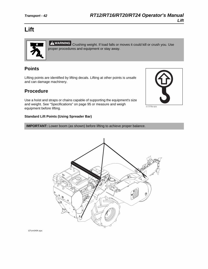
Points
Lifting points are identified by lifting decals. Lifting at other points is unsafe and can damage machinery.
Procedure
Use a hoist and straps or chains capable of supporting the equipment's size and weight. See “Specifications” on page 95 or measure and weigh equipment before lifting.
Standard Lift Points (Using Spreader Bar)
Crushing weight. If load falls or moves it could kill or crush you. Use proper procedures and equipment or stay away.
IMPORTANT: Lower boom (as shown) before lifting to achieve proper balance.

RT12/RT16/RT20/RT24 Operator’s Manual Transport - 43Haul
Haul
Load
1. Disengage parking brake.
2. Start engine.
3. Pull boom control to raise digging boom, but keep it as low as possible.
4. Move unit to rear of trailer and align with ramps or center of trailer bed.
5. Slow engine to low throttle.
6. Move speed/direction control slowly and push to desired speed.
7. Drive unit onto trailer, digging boom first, until tiedown position is reached.
8. Push boom control to lower digging boom, if space allows.
9. Engage parking brake and shutdown unit.
10. Turn fuel shut-off to off position.
11. Tie down unit.
IMPORTANT:
• Unit should be hauled by trailer.
• Transport unit with optional backfill blade, if equipped, in “stowed” position and digging boom lowered.
Crushing weight. If load falls or moves it could kill or crush you. Use proper procedures and equipment or stay away.
NOTICE:
• Load unit with engine in low idle and boom as low as possible.
• Load trailer on level ground.
• Incorrect loading can cause trailer swaying.
• Attach trailer to vehicle before loading or unloading.
• If loading onto a tilt-bed trailer, ensure that tilt latch is secured in the correct position.
• Ten to fifteen percent of total vehicle weight (equipment plus trailer) must be on tongue to help prevent trailer sway.
IMPORTANT: Boom should be facing ramps on trailer.
NOTICE: If loading onto tilt-bed trailer, be prepared for trailer to tilt. Load trencher as far to the front of the trailer as possible.

Transport - 44 RT12/RT16/RT20/RT24 Operator’s ManualHaul
Tie Down
Points
Tiedown points are identified by tiedown decals. Securing to truck or trailer at other points is unsafe and can damage machinery.
Procedure
With Tie-Down Kit on S1A or S2A Trailer
Use pins (shown) to secure front and rear of unit to trailer.

RT12/RT16/RT20/RT24 Operator’s Manual Transport - 45Haul
Without Tie-Down Kit
Loop tiedowns around unit at tiedown points. Make sure tiedowns are tight before transporting.

Transport - 46 RT12/RT16/RT20/RT24 Operator’s ManualTow
Unload
1. Lower trailer or ramps.
2. Remove tiedowns.
3. Open fuel shut-off valve.
4. Start engine.
5. Disengage parking brake.
6. Pull boom control to raise digging boom, but keep it as low as possible.
7. Slow engine to low throttle and slowly back unit down trailer or ramps.
TowUnder normal conditions, unit should not be towed. If unit breaks down and towing is necessary:
• tow for short distances at less than 1 mph (1.6 km/h)
• do not tow for more than 100’ (30 m)
• use no more than 1,300 lb (5800 N) of towing force
Crushing weight. If load falls or moves it could kill or crush you. Use proper procedures and equipment or stay away.
NOTICE:
• Unload unit with engine in low idle and boom as low as possible.
• Unload trailer on level ground.
• Attach trailer to vehicle before loading or unloading.
• If trailer tilts, ensure that tilt latch is secured in the correct position.
NOTICE: If unloading from tilt-bed trailer, be prepared for trailer to tilt.

RT12/RT16/RT20/RT24 Operator’s Manual Transport - 47Tow
Prepare Unit for Towing
1. Ensure parking brake is engaged.
2. Block wheels.
3. Connect to tow point.
4. Turn tow valves (shown) counterclockwise two turns.
5. Unblock wheels.
6. Disengage parking brake.
Return Unit to Normal Operation
1. Engage parking brake.
2. Block wheels.
3. Disconnect from tow point.
4. Turn tow valves clockwise two turns.
5. Unblock wheels.
6. Disengage parking brake.

Transport - 48 RT12/RT16/RT20/RT24 Operator’s ManualTow

RT12/RT16/RT20/RT24 Operator’s Manual Trench - 49
Trench
Chapter Contents
Trench . . . . . . . . . . . . . . . . . . . . . . . . . . . . . . . . . . . 51
Trench - 50 RT12/RT16/RT20/RT24 Operator’s Manual
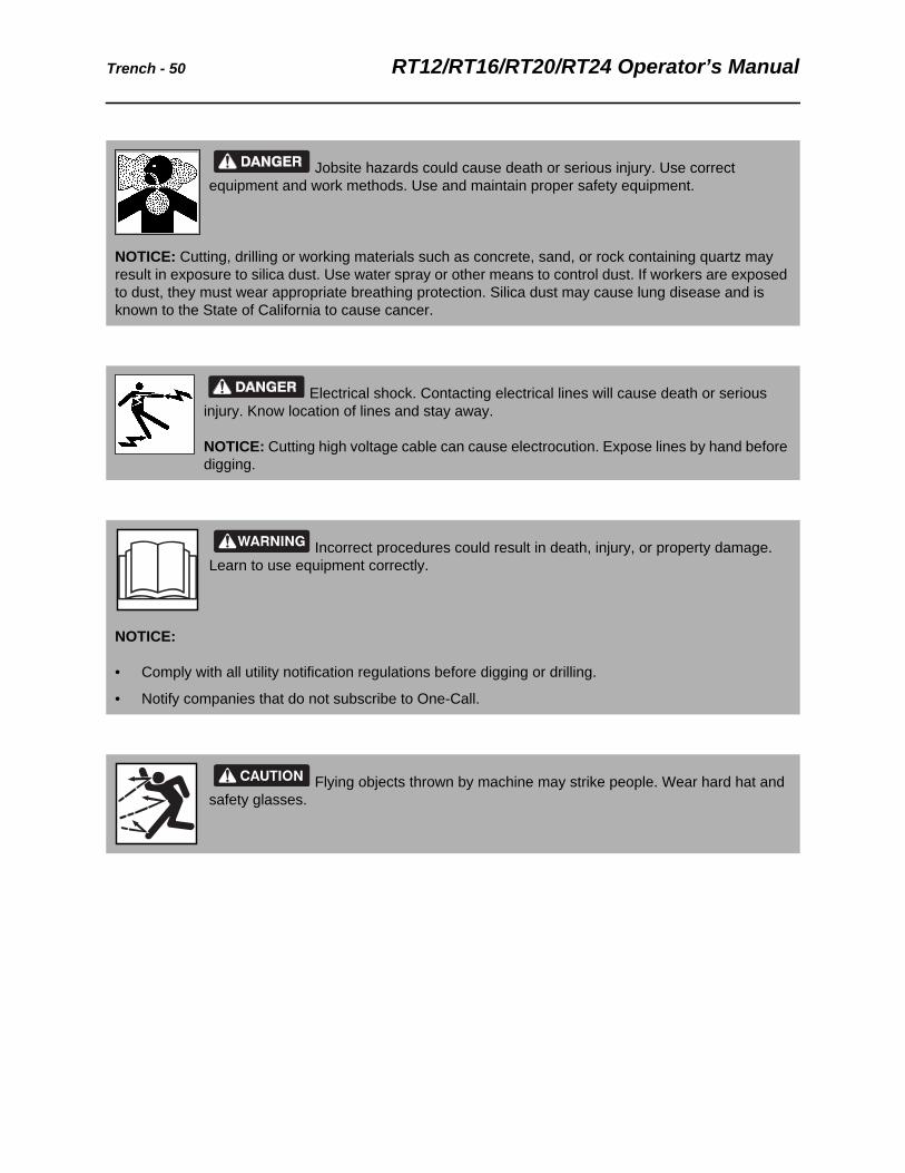
Jobsite hazards could cause death or serious injury. Use correct equipment and work methods. Use and maintain proper safety equipment.
NOTICE: Cutting, drilling or working materials such as concrete, sand, or rock containing quartz may result in exposure to silica dust. Use water spray or other means to control dust. If workers are exposed to dust, they must wear appropriate breathing protection. Silica dust may cause lung disease and is known to the State of California to cause cancer.
Electrical shock. Contacting electrical lines will cause death or serious injury. Know location of lines and stay away.
NOTICE: Cutting high voltage cable can cause electrocution. Expose lines by hand before digging.
Incorrect procedures could result in death, injury, or property damage. Learn to use equipment correctly.
NOTICE:
• Comply with all utility notification regulations before digging or drilling.
• Notify companies that do not subscribe to One-Call.
Flying objects thrown by machine may strike people. Wear hard hat and safety glasses.

RT12/RT16/RT20/RT24 Operator’s Manual Trench - 51Trench
Trench
1. Remove backfill blade, if equipped.
2. Drive trencher to starting point. Move in line with planned trench.
3. Move throttle to half open.
4. Push boom control to lower digging boom to just above ground.
5. Push digging chain control to dig position. DIGGING CHAIN WILL MOVE.
6. Increase engine speed to full throttle.
IMPORTANT:
• Position backfill blade in upright “stowed” position for transporting, keeping digging boom low to the ground. Remove blade for trenching and reinstall for backfilling.
• See “Counterweights” on page 66 for proper counterweights for your unit configuration.
Moving digging teeth will cause death or serious injury. Stay away.
NOTICE:
• Keep everyone at least 6’ (2 m) from machine, digging boom, and its range of movement.
• Machine may move when chain starts to dig. Allow 3’ (1 m) between end of chain and obstacle.
• Digging chain on top side of boom can catch on root or rock, forcing handlebar down suddenly. Stand back from console and hold controls loosely.
EMERGENCY STOP: Release controls and turn ignition switch to OFF position.
IMPORTANT: Trenching movement is toward you.

Trench - 52 RT12/RT16/RT20/RT24 Operator’s ManualTrench
7. Push boom control to slowly lower digging boom to desired trench depth.
8. Move speed/direction control slowly to desired speed.
9. When trench is complete, release speed/direction controls.
10. Move throttle to half open.
11. Pull boom control to raise digging boom to top of trench.
12. Release digging chain control.
13. Reinstall backfill blade in work position for backfilling. After backfilling is completed, position blade in upright “stowed” position for transporting, keeping digging boom low to ground.
14. Drive away from trench.
15. See page 39 for shutdown procedure.
IMPORTANT:
• Do not make sharp turns. Lower boom to full depth when turning.
• If an object becomes lodged in chain, move attachment speed/direction control to neutral and raise boom slightly. Reverse chain direction. If object must be removed manually, turn engine off and engage parking brake.
RT12/RT16/RT20/RT24 Operator’s Manual Drill - 53
CMW
Drill
Chapter Contents
Drilling Attachment. . . . . . . . . . . . . . . . . . . . . . . . . 55
Prepare Jobsite and Equipment . . . . . . . . . . . . . . 55
• Approach Trench. . . . . . . . . . . . . . . . . . . . . . . . . . . . . . . . . . . . . . . . . . 55
• Target Trench . . . . . . . . . . . . . . . . . . . . . . . . . . . . . . . . . . . . . . . . . . . . 55
• Drill Rod and Equipment . . . . . . . . . . . . . . . . . . . . . . . . . . . . . . . . . . . . 56
Drill . . . . . . . . . . . . . . . . . . . . . . . . . . . . . . . . . . . . . . 57
• Using Drill String Guide. . . . . . . . . . . . . . . . . . . . . . . . . . . . . . . . . . . . . 58
Add Rod . . . . . . . . . . . . . . . . . . . . . . . . . . . . . . . . . . 59
Backream. . . . . . . . . . . . . . . . . . . . . . . . . . . . . . . . . 59
Disassemble Joints . . . . . . . . . . . . . . . . . . . . . . . . 60

Drill - 54 RT12/RT16/RT20/RT24 Operator’s Manual
CMW
Turning shaft will kill you or crush arm or leg. Stay away.
NOTICE:
• Keep everybody at least 10’ (3 m) away from drill pipe during operation. Do not straddle trench or drill pipe while drilling.
• If swivel malfunctions, material being installed can rotate.
• To align drill rod when starting a bore, use a guide. Guides are available from your Ditch Witch dealership.
• Keep all persons away from material being installed.
Jobsite hazards could cause death or serious injury. Use correct equipment and work methods. Use and maintain proper safety equipment.
NOTICE: Set up warning barriers and keep people away from equipment and jobsite while drilling.
Incorrect procedures could result in death, injury, or property damage. Learn to use equipment correctly.
Improper control function could cause death or serious injury. If control does not work as described in instructions, stop machine and have it serviced.
NOTICE:
• Do not alter controls.
• Do not tape or tie down switch or lever.
• Improper control function can cause serious injury.
• If releasing control does not stop turning shaft, turn off power supply. Stop drilling. Have unit repaired.
RT12/RT16/RT20/RT24 Operator’s Manual Drill - 55Prepare Jobsite and Equipment
CMW
Prepare Jobsite and Equipment
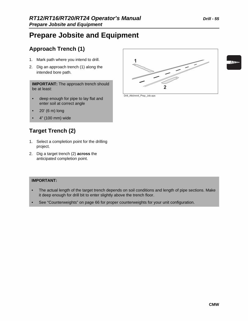
Approach Trench (1)
1. Mark path where you intend to drill.
2. Dig an approach trench (1) along the intended bore path.
Target Trench (2)
1. Select a completion point for the drilling project.
2. Dig a target trench (2) across the anticipated completion point.
IMPORTANT: The approach trench should be at least:
• deep enough for pipe to lay flat and enter soil at correct angle
• 20’ (6 m) long
• 4” (100 mm) wide
IMPORTANT:
• The actual length of the target trench depends on soil conditions and length of pipe sections. Make it deep enough for drill bit to enter slightly above the trench floor.
• See “Counterweights” on page 66 for proper counterweights for your unit configuration.

Drill - 56 RT12/RT16/RT20/RT24 Operator’s ManualPrepare Jobsite and Equipment
CMW
Drill Rod and Equipment
1. Assemble at least 20’ (6 m), but not more than 30’ (9 m), of drill rod.
2. Install drill bit to the cutting end of the drill string.
3. Put drill string in approach trench.
4. Move machine to the approach trench and align the drilling attachment with the intended bore path.
5. Turn off engine.
6. Attach drill string to drilling attachment.
NOTICE: More than 10-15’ (3-4.5 m) of drill rod out of the trench increases the tendency of drill rod to bend.

RT12/RT16/RT20/RT24 Operator’s Manual Drill - 57Drill
CMW
Drill
1. Pull selector valve upward to select drill mode.
2. Start engine and begin clockwise (forward) rotation.
3. Slowly advance machine while maintaining clockwise rotation.
IMPORTANT: For location and description of drilling controls see “Control Console” on page 22.
EMERGENCY SHUTDOWN: Release all controls and turn ignition switch to OFF position.
NOTICE:
• Drilling too quickly causes bit to drift off course and may bend drill rod. After bore path is established, speed may be slightly increased.
• If drill rod starts to bend, stop forward movement of unit and back the unit slightly until rod straightens. Do not drill with bent rod.
• If drill rod hits an obstruction, rotate drill string counterclockwise to back up slightly.
Drill - 58 RT12/RT16/RT20/RT24 Operator’s ManualDrill
CMW
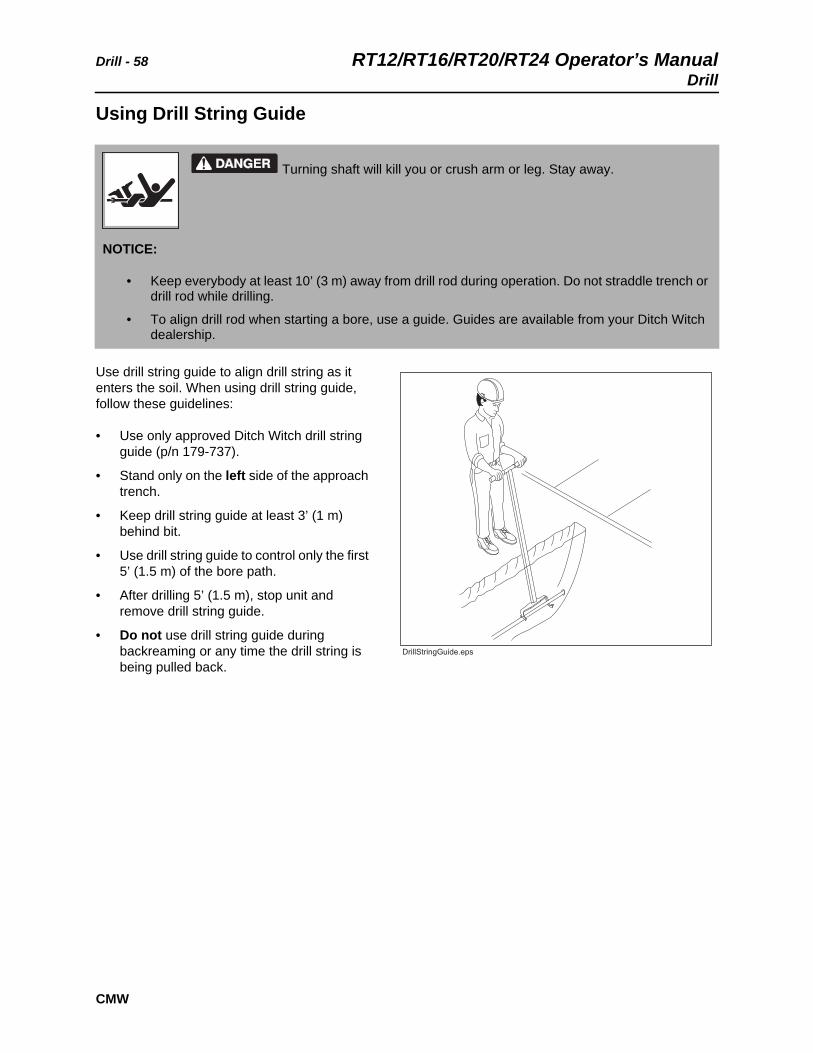
Using Drill String Guide
Use drill string guide to align drill string as it enters the soil. When using drill string guide, follow these guidelines:
• Use only approved Ditch Witch drill string guide (p/n 179-737).
• Stand only on the left side of the approach trench.
• Keep drill string guide at least 3’ (1 m) behind bit.
• Use drill string guide to control only the first 5’ (1.5 m) of the bore path.
• After drilling 5’ (1.5 m), stop unit and remove drill string guide.
• Do not use drill string guide during backreaming or any time the drill string is being pulled back.
Turning shaft will kill you or crush arm or leg. Stay away.
NOTICE:
• Keep everybody at least 10’ (3 m) away from drill rod during operation. Do not straddle trench or drill rod while drilling.
• To align drill rod when starting a bore, use a guide. Guides are available from your Ditch Witch dealership.
RT12/RT16/RT20/RT24 Operator’s Manual Drill - 59Add Rod
CMW
Add Rod
1. Use control to stop drilling attachment.
2. Use ground drive controls to back up unit 6” (150 mm) to loosen drill rod in ground.
3. Disconnect drill rod from drilling attachment.
4. Use ground drive controls to move unit away from bore.
5. Add one drill rod to continue bore.
• Have a helper direct unit operator to align drilling attachment with new rod and stop when drilling attachment and rod are 1” (25 mm) apart.
• Have a helper lightly hold rod and direct unit operator to move unit forward slowly.
• As soon as rod begins to engage drilling attachment, have helper release rod and move hands and arms clear of drilling attachment.
BackreamAfter drill bit enters target trench, the bore hole may be enlarged by changing the drill bit to a backreamer and drawing it back through the initial bore.
1. Turn ignition switch to OFF position.
2. Replace drill bit with backreamer.
3. Start engine and begin clockwise rotation.
4. Slowly back up machine while maintaining rotation.
5. When backreamer exits the bore hole, stop rotation immediately.
IMPORTANT: It is recommended that a helper be used to add drill rod.
IMPORTANT: Always rotate clockwise during backreaming. Rotate counterclockwise only to dislodge a dry bore bit or reamer that has seized in the bore hole.
IMPORTANT:
• Do not try to increase hole size too much in one pass. Several passes using successively larger reamers will save wear on machine.
• During backreaming, keep drill string straight. Sharp bends in the drill rod at the motor coupling can cause rod failure.
Drill - 60 RT12/RT16/RT20/RT24 Operator’s ManualDisassemble Joints
CMW
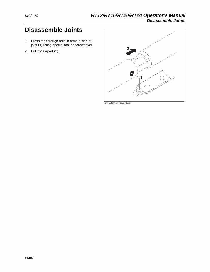
Disassemble Joints1. Press tab through hole in female side of
joint (1) using special tool or screwdriver.
2. Pull rods apart (2).

RT12/RT16/RT20/RT24 Operator’s Manual Systems and Equipment - 61
Systems and Equipment
Chapter Contents
Chain, Teeth, and Sprockets . . . . . . . . . . . . . . . . . 62
• Chain and Tooth Maintenance . . . . . . . . . . . . . . . . . . . . . . . . . . . . . . . 62
• Chain Types . . . . . . . . . . . . . . . . . . . . . . . . . . . . . . . . . . . . . . . . . . . . . 62
• Chain Selection . . . . . . . . . . . . . . . . . . . . . . . . . . . . . . . . . . . . . . . . . . . 63
Optional Equipment . . . . . . . . . . . . . . . . . . . . . . . . 64
• Backfill blade. . . . . . . . . . . . . . . . . . . . . . . . . . . . . . . . . . . . . . . . . . . . . 65
• Drilling attachment . . . . . . . . . . . . . . . . . . . . . . . . . . . . . . . . . . . . . . . . 65
• Counterweights . . . . . . . . . . . . . . . . . . . . . . . . . . . . . . . . . . . . . . . . . . . 66
Systems and Equipment - 62 RT12/RT16/RT20/RT24 Operator’s ManualChain, Teeth, and Sprockets
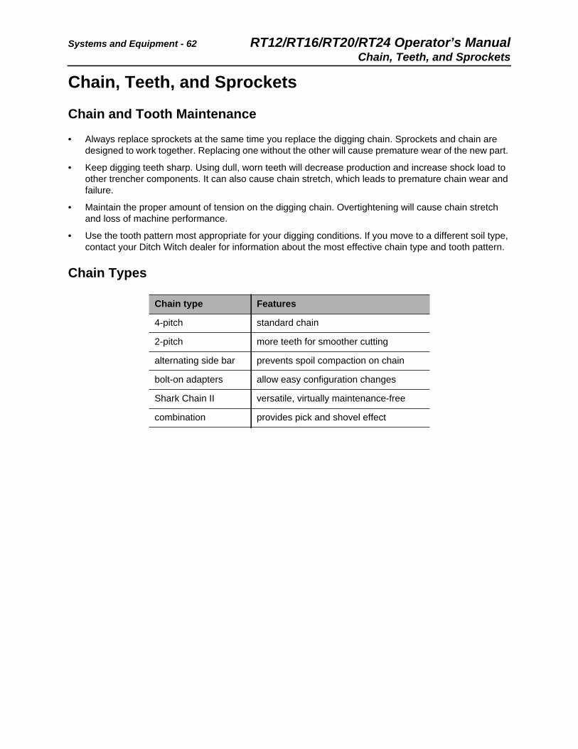
Chain, Teeth, and Sprockets
Chain and Tooth Maintenance
• Always replace sprockets at the same time you replace the digging chain. Sprockets and chain are designed to work together. Replacing one without the other will cause premature wear of the new part.
• Keep digging teeth sharp. Using dull, worn teeth will decrease production and increase shock load to other trencher components. It can also cause chain stretch, which leads to premature chain wear and failure.
• Maintain the proper amount of tension on the digging chain. Overtightening will cause chain stretch and loss of machine performance.
• Use the tooth pattern most appropriate for your digging conditions. If you move to a different soil type, contact your Ditch Witch dealer for information about the most effective chain type and tooth pattern.
Chain Types
Chain type Features
4-pitch standard chain
2-pitch more teeth for smoother cutting
alternating side bar prevents spoil compaction on chain
bolt-on adapters allow easy configuration changes
Shark Chain II versatile, virtually maintenance-free
combination provides pick and shovel effect

RT12/RT16/RT20/RT24 Operator’s Manual Systems and Equipment - 63Chain, Teeth, and Sprockets
Chain Selection
These charts are meant as a guideline only. No one chain type works well in all conditions. See your Ditch Witch dealer for soil conditions and chain recommendations for your area. Ask for the latest Chain, Teeth, and Sprockets Parts Catalog.
• 1 = best
• 2 = better
• 3 = good
• 4 = not recommended
Chain Sandy Soil
Soft Soil Medium Soil
Hard Soil Rocky Soil
Sticky Soil
4-pitch cup tooth 3 1 2 3 4 1
2-pitch cup tooth 2 3 1 1 3 4
bolt-on adaptor, 2-pitch 4 4 3 2 1 4
bolt-on adaptor/cup tooth combo
4 3 2 1 2 4
Shark Chain II 4 3 2 1 1 4
alternating side bar 4 4 4 4 4 1
Soil Description
sandy soil sugar sand, blow sand, or other soils where sand is the predominant component
soft soil sandy loam
medium soil loams, loamy clays
hard soil packed clays, gumbo, all compacted soils
rocky soil chunk rock, glacial till, cobble, rip rap, gravel
sticky soil gumbo, sticky clays

Systems and Equipment - 64 RT12/RT16/RT20/RT24 Operator’s ManualOptional Equipment
Optional EquipmentSee your Ditch Witch dealer for more information about the following optional equipment.
NOTICE: Adding or removing optional equipment changes counterweight requirement. See chart on page 67 or page 68 to ensure you have the correct counterweights for your configuration.
Equipment Description
booms provide depth options of 24” (610-mm), 30” (760-mm), or 48” (1220 mm); each length is available with either an adjustment screw or grease cylinder for tensioning the digging chain
mechanical trench cleaner removes spoils from the trench floor
remote air filter option on RT12 or RT16, provides extra filtering capacity for dusty conditions
turf tires minimize turf disturbance
hourmeter/tachometer displays engine operating times and engine speed
backfill blade cover trench using machine
drilling attachment drill under sidewalks and driveways
counterbalance weights customize unit balance in various configurations
10-tooth sprocket slows digging chain speed to allow teeth time to penetrate into the ground and increase performance in rocky or extremely hard soil
wheel tracks improve traction over rough terrain

RT12/RT16/RT20/RT24 Operator’s Manual Systems and Equipment - 65Optional Equipment
Backfill Blade
The optional backfill blade slides onto a mounting stub (2). When transporting, it is stowed and latched in the upright position using a single pin (1). Remove blade for trenching and reinstall in work position for backfilling.
To use the backfill blade, remove pin (1), slide the blade onto the stub (2) in work position, then secure with pin.
After backfilling is completed, position blade in upright “stowed” position and low to the ground for transporting.
Drilling Attachment
The optional drilling attachment option can be used to drill under obstructions such as sidewalks and driveways. For operational information, see “Drill” on page 53.
NOTICE: Position backfill blade in upright “stowed” position for transporting, keeping digging boom low to the ground. Remove blade for trenching and reinstall for backfilling.
Systems and Equipment - 66 RT12/RT16/RT20/RT24 Operator’s ManualOptional Equipment
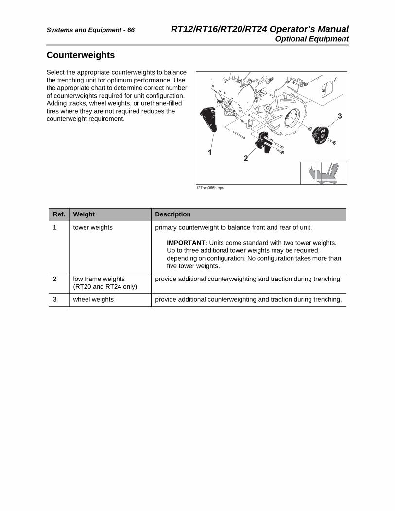
Counterweights
Select the appropriate counterweights to balance the trenching unit for optimum performance. Use the appropriate chart to determine correct number of counterweights required for unit configuration. Adding tracks, wheel weights, or urethane-filled tires where they are not required reduces the counterweight requirement.
Ref. Weight Description
1 tower weights primary counterweight to balance front and rear of unit.
IMPORTANT: Units come standard with two tower weights. Up to three additional tower weights may be required, depending on configuration. No configuration takes more than five tower weights.
2 low frame weights (RT20 and RT24 only)
provide additional counterweighting and traction during trenching
3 wheel weights provide additional counterweighting and traction during trenching.
RT12/RT16/RT20/RT24 Operator’s Manual Systems and Equipment - 67Optional Equipment
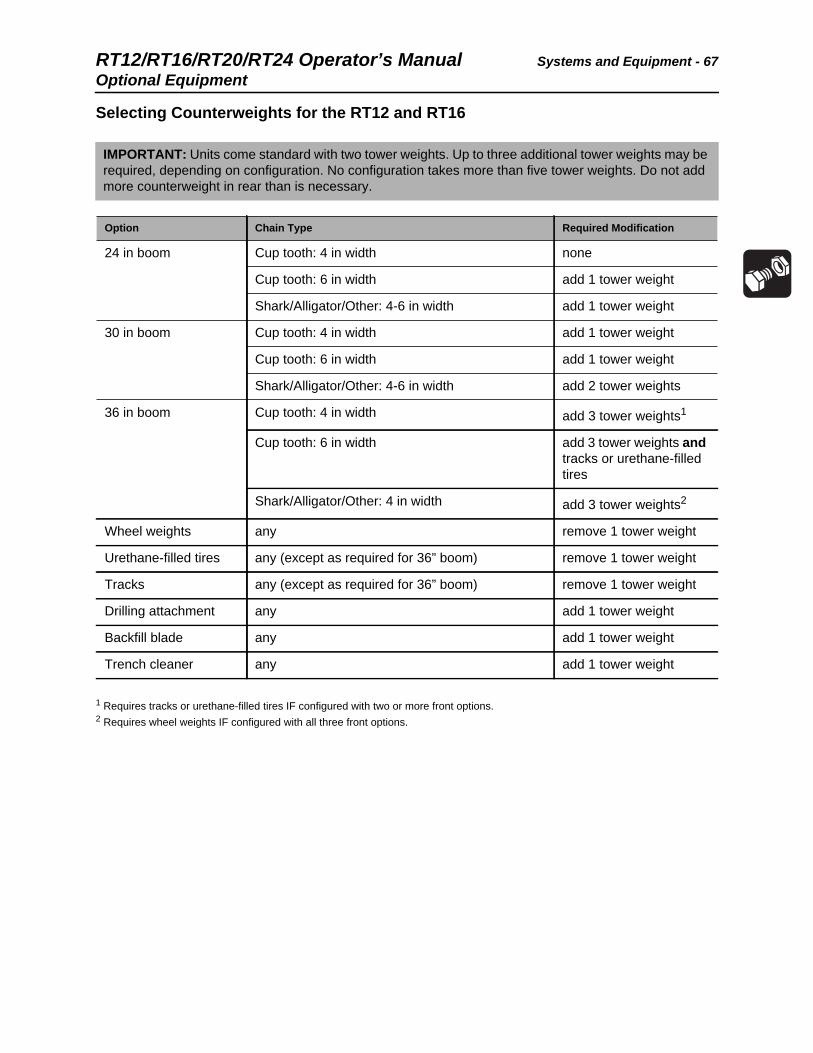
Selecting Counterweights for the RT12 and RT16
1 Requires tracks or urethane-filled tires IF configured with two or more front options.2 Requires wheel weights IF configured with all three front options.
IMPORTANT: Units come standard with two tower weights. Up to three additional tower weights may be required, depending on configuration. No configuration takes more than five tower weights. Do not add more counterweight in rear than is necessary.
Option Chain Type Required Modification
24 in boom Cup tooth: 4 in width none
Cup tooth: 6 in width add 1 tower weight
Shark/Alligator/Other: 4-6 in width add 1 tower weight
30 in boom Cup tooth: 4 in width add 1 tower weight
Cup tooth: 6 in width add 1 tower weight
Shark/Alligator/Other: 4-6 in width add 2 tower weights
36 in boom Cup tooth: 4 in width add 3 tower weights1
Cup tooth: 6 in width add 3 tower weights and tracks or urethane-filled tires
Shark/Alligator/Other: 4 in width add 3 tower weights2
Wheel weights any remove 1 tower weight
Urethane-filled tires any (except as required for 36” boom) remove 1 tower weight
Tracks any (except as required for 36” boom) remove 1 tower weight
Drilling attachment any add 1 tower weight
Backfill blade any add 1 tower weight
Trench cleaner any add 1 tower weight

Systems and Equipment - 68 RT12/RT16/RT20/RT24 Operator’s ManualOptional Equipment
Selecting Counterweights for the RT20 and RT24
1 Requires tracks or urethane-filled tires IF configured with two or more front options.2 Requires wheel weights IF configured with all three front options.
IMPORTANT: Units come standard with two tower weights. Up to three additional tower weights may be required, depending on configuration. No configuration takes more than five tower weights. Do not add more counterweight in rear than is necessary.
Option Chain Type Required Modification
24 in boom Cup tooth: 4 in width none
Cup tooth: 6 in width add 1 tower weight
Cup tooth: 8 in width (RT24 only) add 2 tower weights
Shark/Alligator/Other: 4-6 in width add 1 tower weight
Shark/Alligator/Other: 8 in width (RT24 only)
add 3 tower weights
30 in boom Cup tooth: 4-6 in width add 1 tower weight
Cup tooth: 8 in width (RT24 only) add 2 tower weights
Shark/Alligator/Other: 4-6 in width add 2 tower weights
Shark/Alligator/Other: 8 in width (RT24 only)
add 3 tower weights and tracks or urethane-filled tires
36 in boom Cup tooth: 4 in width add 3 tower weights1
Cup tooth: 6 in width add 3 tower weights and tracks or urethane-filled tires
Cup tooth: 8 in width (RT24 only) add 3 tower weights and tracks or urethane-filled tires2
Shark/Alligator/Other: 4 in width add 3 tower weights and tracks or urethane-filled tires2
48 in boom (RT24 only) Cup tooth: 4-6 in width add 3 tower weights and tracks or urethane-filled tires and wheel weights
Cup tooth: 8 in width add 3 tower weights and tracks or urethane-filled tires and wheel weights and low frame weights
Shark/Alligator/Other: 4 in width add 3 tower weights and tracks or urethane-filled tires and wheel weights and low frame weights
Wheel weights any (except as required for 48” boom) remove 1 tower weight
Urethane-filled tires any (except as required for 36” boom) remove 1 tower weight
Tracks any (except as required for 36” boom) remove 1 tower weight
Drilling attachment any add 1 tower weight
Backfill blade any add 1 tower weight
Trench cleaner any add 1 tower weight
RT12/RT16/RT20/RT24 Operator’s Manual Complete the Job - 69
CMW
Complete the Job
Chapter Contents
Restore Jobsite . . . . . . . . . . . . . . . . . . . . . . . . . . . . 70
Rinse Equipment . . . . . . . . . . . . . . . . . . . . . . . . . . 70
Stow Tools . . . . . . . . . . . . . . . . . . . . . . . . . . . . . . . 70

Complete the Job - 70 RT12/RT16/RT20/RT24 Operator’s ManualRestore Jobsite
CMW
Restore JobsiteAfter product is installed, return spoils to the trench with optional backfill blade, shovels, or small earth-moving equipment. See optional backfill blade on page 65.
Rinse EquipmentSpray water onto equipment to remove dirt and mud. Lubricate all zerks.
Stow ToolsMake sure all bits, pullback devices, and other tools are loaded and properly secured on trailer.
NOTICE: Do not spray water onto operator’s console. Electrical components could be damaged. Wipe down instead.

RT12/RT16/RT20/RT24 Operator’s Manual Service - 71
CMW
Service
Chapter Contents
Precautions . . . . . . . . . . . . . . . . . . . . . . . . . . . . . . . 72
Recommended Lubricants/Service Key . . . . . . . . 73
Oil Temperature Chart . . . . . . . . . . . . . . . . . . . . . . 74
Each Use . . . . . . . . . . . . . . . . . . . . . . . . . . . . . . . . . 76
10 Hour . . . . . . . . . . . . . . . . . . . . . . . . . . . . . . . . . . 83
50 Hour . . . . . . . . . . . . . . . . . . . . . . . . . . . . . . . . . . 88
100 Hour . . . . . . . . . . . . . . . . . . . . . . . . . . . . . . . . . 89
250 Hour . . . . . . . . . . . . . . . . . . . . . . . . . . . . . . . . . 92
As Needed . . . . . . . . . . . . . . . . . . . . . . . . . . . . . . . 93
Service - 72 RT12/RT16/RT20/RT24 Operator’s ManualPrecautions
CMW
Precautions
Welding Precaution
Cleaning Precaution
Incorrect procedures could result in death, injury, or property damage. Learn to use equipment correctly.
NOTICES:
• Unless otherwise instructed, all service should be performed with engine off.
• Refer to engine manufacturer’s manual for engine maintenance instructions.
• Before servicing equipment, lower unstowed attachments to ground.
NOTICE: Welding can damage electronics.
• Disconnect battery at battery disconnect switch before welding to prevent damage to battery.
• Connect welder ground clamp close to welding point and make sure no electronic components are in the ground path.
NOTICE: When cleaning equipment, do not spray electrical components with water.

RT12/RT16/RT20/RT24 Operator’s Manual Service - 73Recommended Lubricants/Service Key
CMW
Recommended Lubricants/Service Key
Proper lubrication and maintenance protects Ditch Witch equipment from damage and failure. Service intervals listed are for minimum requirements. In extreme conditions, service machine more frequently. Use only recommended lubricants.
For more information on engine lubrication and maintenance, see your engine manual.
Item Description
DEO Diesel engine oil meeting API service classification CF-4 or E1-96 and SAE viscosity recommended by engine manufacturer (SAE15W40)
GEO Gasoline engine oil meeting or exceeding API SJ. See oil temperature chart for recommended viscosity grade for each model.
MPG Multipurpose grease meeting ASTM D217 and NLGI 2
MPL Multipurpose gear oil meeting API service classification GL-5 (SAE 80W90)
Check level of fluid or lubricant
Check condition
Filter
Change, replace, adjust, service or test
NOTICE:
• Use only genuine Ditch Witch parts, filters, approved lubricants, TJC, and approved coolants to maintain warranty.
• Use the “Service Record” on page 113 to record all required service to your machine.

Service - 74 RT12/RT16/RT20/RT24 Operator’s ManualEngine Oil Temperature Chart
CMW
Engine Oil Temperature Chart
RT12 Honda IGX390
RT16 Briggs & Stratton
Temperature range anticipated before next oil change
Temperature range anticipated before next oil change
RT12/RT16/RT20/RT24 Operator’s Manual Service - 75Engine Oil Temperature Chart
CMW
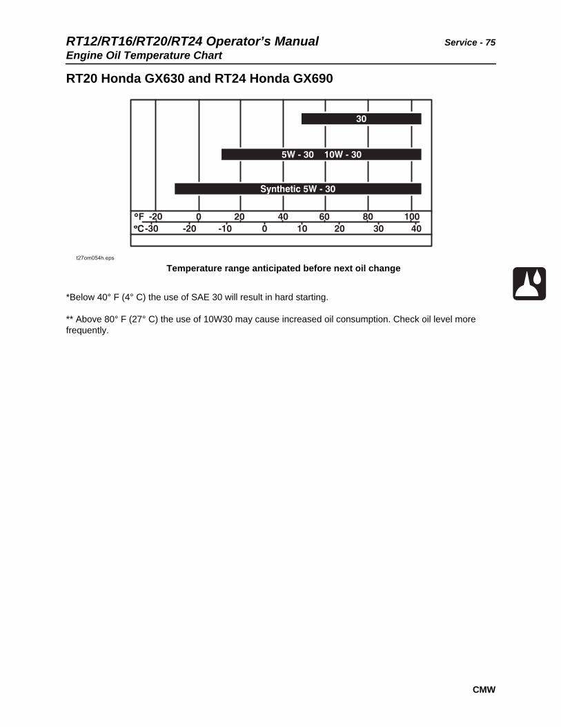
RT20 Honda GX630 and RT24 Honda GX690
*Below 40° F (4° C) the use of SAE 30 will result in hard starting.
** Above 80° F (27° C) the use of 10W30 may cause increased oil consumption. Check oil level more frequently.
Temperature range anticipated before next oil change

Service - 76 RT12/RT16/RT20/RT24 Operator’s ManualEach Use
CMW
Each Use
Check Engine Oil Level
RT12 Honda iGX390
Check engine oil at dipstick before each use. If low, add GEO until oil level is at highest line on dipstick.
Location Task Notes
Engine Check engine oil level GEO
Check air filter elements
Trencher Check hydraulic fluid level DEO (15W30 with PowerUp additive)
Check hydraulic fluid cooler
Check hydraulic hoses
Check rear tire pressures 15 psi (1 bar) bar lug tires22 psi (1.5 bar) turf tires
Check lug nut torque 85 ft•lb (115 N•m)
Check parking brake operation
IMPORTANT: For more information on engine oil, see “Recommended Lubricants/Service Key” on page 73 or see engine manual.
RT12/RT16/RT20/RT24 Operator’s Manual Service - 77Each Use
CMW
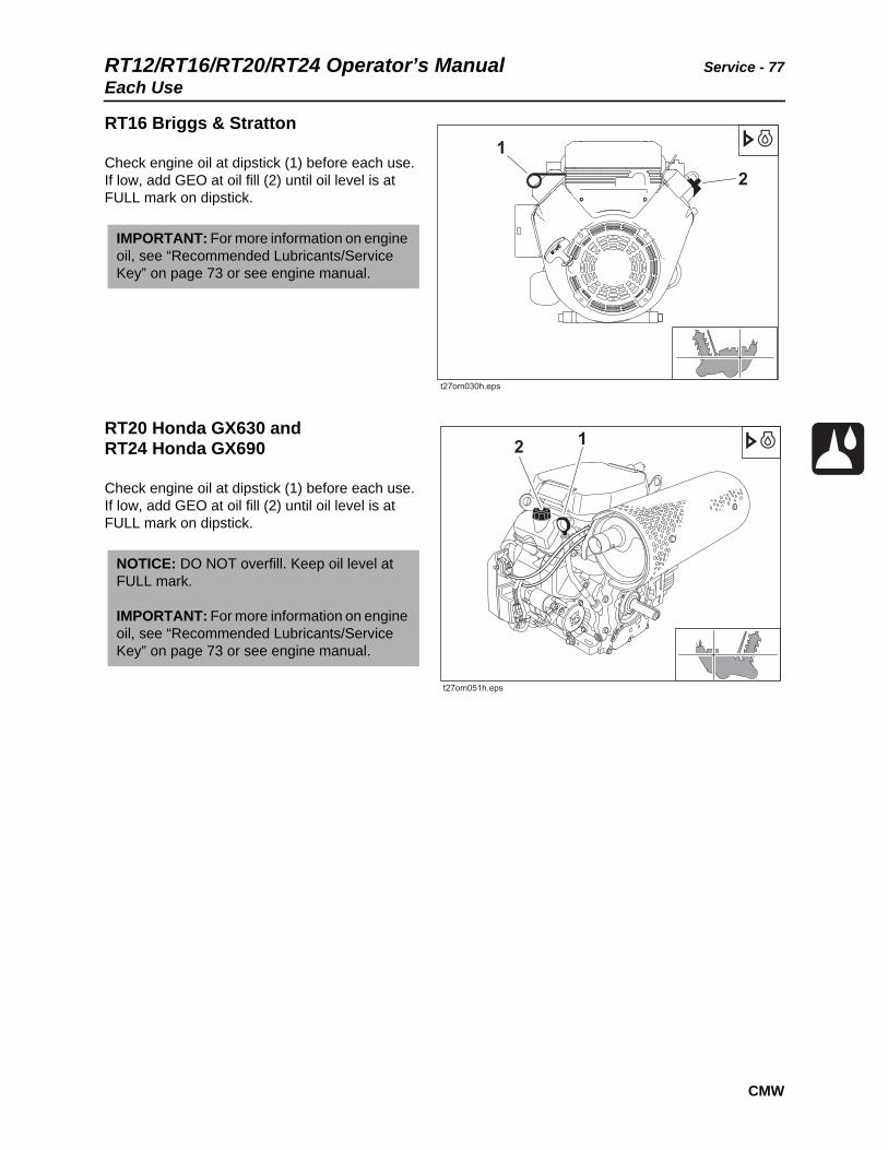
RT16 Briggs & Stratton
Check engine oil at dipstick (1) before each use. If low, add GEO at oil fill (2) until oil level is at FULL mark on dipstick.
RT20 Honda GX630 andRT24 Honda GX690
Check engine oil at dipstick (1) before each use. If low, add GEO at oil fill (2) until oil level is at FULL mark on dipstick.
IMPORTANT: For more information on engine oil, see “Recommended Lubricants/Service Key” on page 73 or see engine manual.
NOTICE: DO NOT overfill. Keep oil level at FULL mark.
IMPORTANT: For more information on engine oil, see “Recommended Lubricants/Service Key” on page 73 or see engine manual.

Service - 78 RT12/RT16/RT20/RT24 Operator’s ManualEach Use
CMW
Check Air Filter Elements
RT12
Check air filter element before each use. Replace element if it is dirty or damaged.
To check:
1. Remove air cleaner cover nut and air cleaner cover.
2. Remove wing nut, air cleaner elements (paper and foam), and air cleaner elbow packing and separate them.
3. Inspect elements for wear and replace if damaged.
4. Inspect air cleaner elbow packing for deterioration and replace if damaged.
RT12 Optional Air Filter
Replace optional air filter as needed.
NOTICE: Change the elements. Do not attempt to clean them.
• Compressed air or water may damage the elements.
• Tapping filter elements to loosen dirt may damage the elements.
NOTICE: Change the elements,. Do not attempt to clean them.
• Compressed air or water may damage the elements.
• Tapping filter elements to loosen dirt may damage the elements.

RT12/RT16/RT20/RT24 Operator’s Manual Service - 79Each Use
CMW
RT16
Check air filter element before each use. Replace element if it is dirty or damaged.
To check:
1. Remove wing nuts and air cleaner cover.
2. Remove element and replace if dirty.
RT20 and RT24
Check air filter element before each use. Replace element if it is dirty or damaged.
To check:
1. Lift latches on plastic cover and remove.
2. Remove wing nut and air cleaner cover.
3. Inspect paper and foam elements. Replace if dirty.
NOTICE: Change the elements. Do not attempt to clean them.
• Compressed air or water may damage the elements.
• Tapping filter elements to loosen dirt may damage the elements.
NOTICE: Change the elements. Do not attempt to clean them.
• Compressed air or water may damage the elements.
• Tapping filter elements to loosen dirt may damage the elements.

Service - 80 RT12/RT16/RT20/RT24 Operator’s ManualEach Use
CMW
Check Hydraulic Fluid Level
With digging boom fully raised, check hydraulic fluid at sight glass (1) before each use. If low, add SAE15W40 with PowerUp additive until fluid level is at mid-level in sight glass. Clean dust from cap (2) by blowing with low pressure air.
Add 16 oz (0.47 L) of Power Up oil additive or equivalent to 8 gal (30.28 L) of SAE15W40 for use as hydraulic fluid. Fill hydraulic reservoir to correct level on sight glass.
Check Hydraulic Fluid Cooler
Check hydraulic fluid cooler before each use. If dirty, clean by blowing with low pressure air. For extensive cleaning, remove cover.
NOTICE:
• Hydraulic reservoir can become pressurized. OPEN SLOWLY.
• Use SAE15W40 with additive for hydraulic fluid in these machines.
• Contact your Ditch Witch dealer for Power Up additive.
RT12/RT16/RT20/RT24 Operator’s Manual Service - 81Each Use
CMW
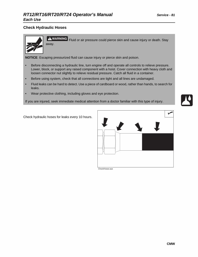
Check Hydraulic Hoses
Check hydraulic hoses for leaks every 10 hours.
Fluid or air pressure could pierce skin and cause injury or death. Stay away.
NOTICE: Escaping pressurized fluid can cause injury or pierce skin and poison.
• Before disconnecting a hydraulic line, turn engine off and operate all controls to relieve pressure. Lower, block, or support any raised component with a hoist. Cover connection with heavy cloth and loosen connector nut slightly to relieve residual pressure. Catch all fluid in a container.
• Before using system, check that all connections are tight and all lines are undamaged.
• Fluid leaks can be hard to detect. Use a piece of cardboard or wood, rather than hands, to search for leaks.
• Wear protective clothing, including gloves and eye protection.
If you are injured, seek immediate medical attention from a doctor familiar with this type of injury.
Service - 82 RT12/RT16/RT20/RT24 Operator’s ManualEach Use
CMW
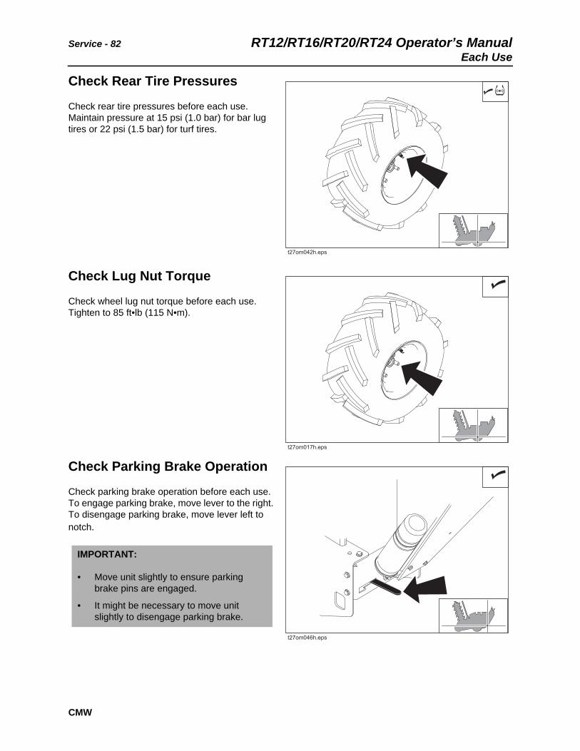
Check Rear Tire Pressures
Check rear tire pressures before each use. Maintain pressure at 15 psi (1.0 bar) for bar lug tires or 22 psi (1.5 bar) for turf tires.
Check Lug Nut Torque
Check wheel lug nut torque before each use. Tighten to 85 ft•lb (115 N•m).
Check Parking Brake Operation
Check parking brake operation before each use. To engage parking brake, move lever to the right. To disengage parking brake, move lever left to notch.
IMPORTANT:
• Move unit slightly to ensure parking brake pins are engaged.
• It might be necessary to move unit slightly to disengage parking brake.

RT12/RT16/RT20/RT24 Operator’s Manual Service - 8310 Hour Service
CMW
10 Hour Service
Change Engine Oil
RT12
Change engine oil after the first 10 hours of operation and every 100 hours thereafter.
1. Drain at plug (1) while oil is still warm.
2. Replace plug.
3. Slowly add GEO at fill (2).
Location Task Notes
Engine Change engine oil Initial, GEO
Trencher Lube pivot MPG
Lube trail wheel MPG
Lube auger bearing MPG
Lube wheel tracks, if equipped MPG
Check digging chain tension MPG
IMPORTANT: Engine oil capacity is 1.16 qts (1.1 L). Do not overfill.
Service - 84 RT12/RT16/RT20/RT24 Operator’s Manual10 Hour Service
CMW
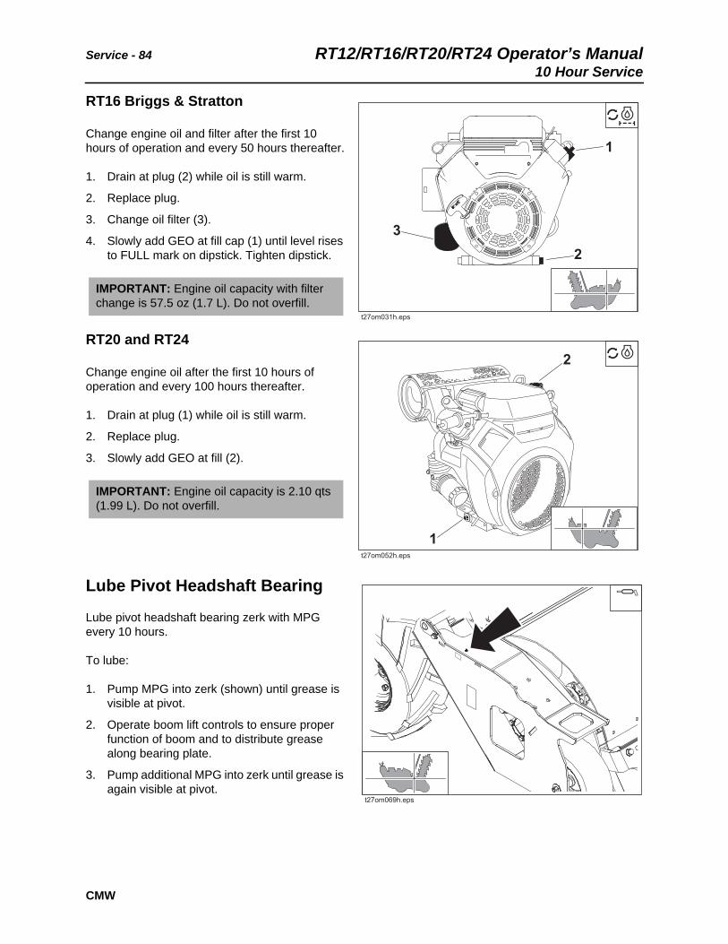
RT16 Briggs & Stratton
Change engine oil and filter after the first 10 hours of operation and every 50 hours thereafter.
1. Drain at plug (2) while oil is still warm.
2. Replace plug.
3. Change oil filter (3).
4. Slowly add GEO at fill cap (1) until level rises to FULL mark on dipstick. Tighten dipstick.
RT20 and RT24
Change engine oil after the first 10 hours of operation and every 100 hours thereafter.
1. Drain at plug (1) while oil is still warm.
2. Replace plug.
3. Slowly add GEO at fill (2).
Lube Pivot Headshaft Bearing
Lube pivot headshaft bearing zerk with MPG every 10 hours.
To lube:
1. Pump MPG into zerk (shown) until grease is visible at pivot.
2. Operate boom lift controls to ensure proper function of boom and to distribute grease along bearing plate.
3. Pump additional MPG into zerk until grease is again visible at pivot.
IMPORTANT: Engine oil capacity with filter change is 57.5 oz (1.7 L). Do not overfill.
IMPORTANT: Engine oil capacity is 2.10 qts (1.99 L). Do not overfill.
t27om069h.eps

RT12/RT16/RT20/RT24 Operator’s Manual Service - 8510 Hour Service
CMW
Lube Pivot Bushing
Lube pivot bushing zerk with MPG every 10 hours.
Lube Trail Wheel
Lube trail wheel zerk with MPG every 10 hours.
Lube Auger Bearing
Lube auger bearing zerk with MPG every 10 hours.

Service - 86 RT12/RT16/RT20/RT24 Operator’s Manual10 Hour Service
CMW
Lube Wheel Tracks
Lube wheel tracks, if equipped, at zerk with MPG every 10 hours.
Check Digging Chain Tension
Check digging chain tension every 10 hours and adjust as needed. With boom horizontal, measure distance A from bottom of boom to chain. When properly tensioned, distance A should be 1.5-2.0” (38-51 mm).
Adjustment Screw:
1. Loosen four clamp bolts (2) so that boom slides freely.
2. Loosen jam nut on adjustment screw (1).
3. To tighten digging chain, turn adjustment screw clockwise. To loosen digging chain, turn counterclockwise.
4. When proper tension is reached, tighten jam nut.
5. Torque clamp bolts to 75 ft•lb (102 N•m).
Grease Cylinder:
NOTICE: Do not overtighten chain. Overtightening will cause chain stretch, loss of machine performance, and possible premature chain failure.
Fluid pressure could pierce skin and cause injury or death. Stay away.
NOTICE: Service digging boom grease cylinder only while standing on opposite side of boom. Wear gloves and safety glasses and cover fitting with cloth when relieving pressure in cylinder.
RT12/RT16/RT20/RT24 Operator’s Manual Service - 8710 Hour Service
CMW
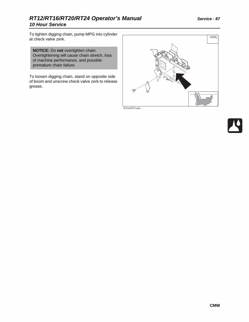
To tighten digging chain, pump MPG into cylinder at check valve zerk.
To loosen digging chain, stand on opposite side of boom and unscrew check valve zerk to release grease.
NOTICE: Do not overtighten chain. Overtightening will cause chain stretch, loss of machine performance, and possible premature chain failure.
Service - 88 RT12/RT16/RT20/RT24 Operator’s Manual50 Hour Service
CMW
50 Hour Service
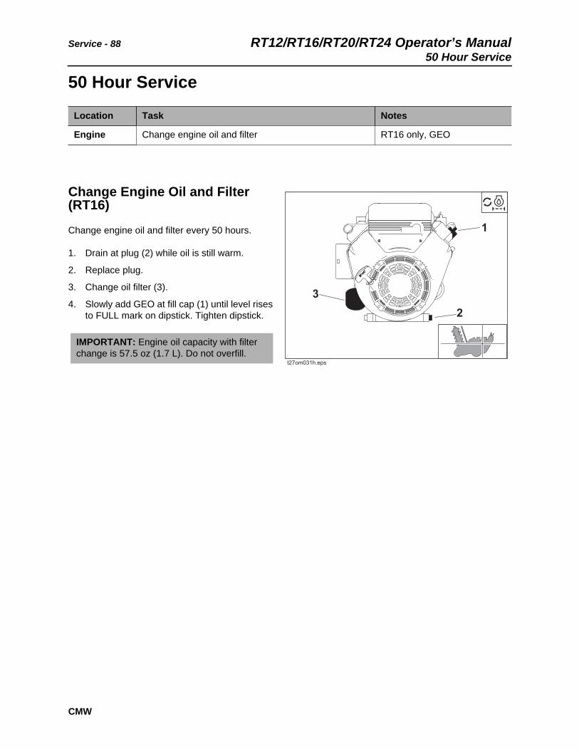
Change Engine Oil and Filter (RT16)
Change engine oil and filter every 50 hours.
1. Drain at plug (2) while oil is still warm.
2. Replace plug.
3. Change oil filter (3).
4. Slowly add GEO at fill cap (1) until level rises to FULL mark on dipstick. Tighten dipstick.
Location Task Notes
Engine Change engine oil and filter RT16 only, GEO
IMPORTANT: Engine oil capacity with filter change is 57.5 oz (1.7 L). Do not overfill.

RT12/RT16/RT20/RT24 Operator’s Manual Service - 89100 Hour Service
CMW
100 Hour Service
Change Engine Oil
RT12
Change engine oil after the first 10 hours of operation and every 100 hours thereafter.
1. Drain at plug (1) while oil is still warm.
2. Replace plug.
3. Slowly add GEO at fill (2).
RT20 and RT24
Change engine oil and filter after the first 10 hours of operation and every 100 hours thereafter.
1. Drain at plug (1) while oil is still warm.
2. Replace plug.
3. Change spin-on oil filter, (3).
4. Slowly add GEO at fill (2).
Location Task Notes
Engine Change engine oil Honda engines, GEO
Change air filter elements
Check spark plug
IMPORTANT: Engine oil capacity is 1.16 qts (1.10 L). Do not overfill.
IMPORTANT: Engine oil capacity is 2.10 qts (1.99 L). Do not overfill.

Service - 90 RT12/RT16/RT20/RT24 Operator’s Manual100 Hour Service
CMW
Change Air Filter Elements
RT12 Standard Air Filter
Change air filter elements every 100 hours.
To change:
1. Remove wing nut (6) and air cleaner cover (5).
2. Remove wing nut (4) and remove elements (2, 3).
3. Reverse procedure to install new elements. Ensure gasket (1) is seated properly.
RT12 Optional Air Filter
Change optional air filter elements, if equipped, every 100 hours.
IMPORTANT: If operating in extremely dusty conditions, change filter more frequently.
NOTICE: Change the elements. Do not attempt to clean them.
• Compressed air or water may damage the elements.
• Tapping filter elements to loosen dirt may damage the elements.
RT12/RT16/RT20/RT24 Operator’s Manual Service - 91100 Hour Service
CMW
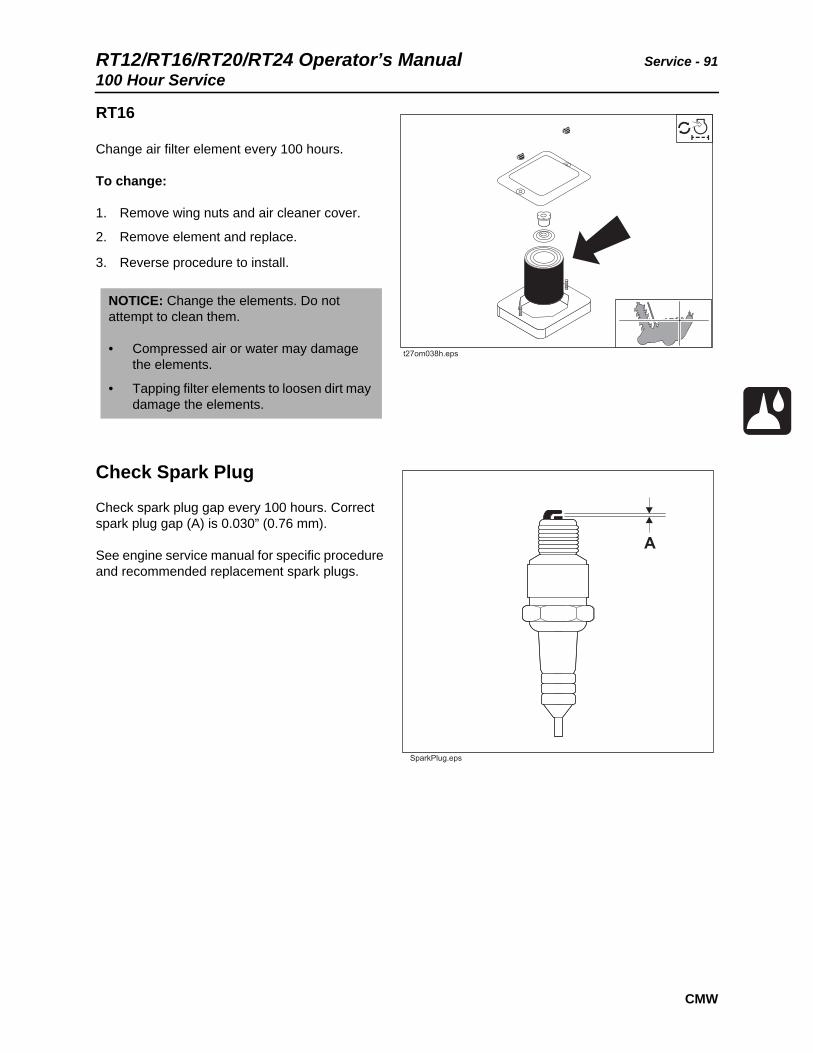
RT16
Change air filter element every 100 hours.
To change:
1. Remove wing nuts and air cleaner cover.
2. Remove element and replace.
3. Reverse procedure to install.
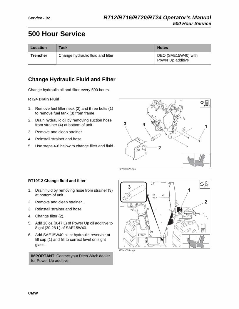
Check Spark Plug
Check spark plug gap every 100 hours. Correct spark plug gap (A) is 0.030” (0.76 mm).
See engine service manual for specific procedure and recommended replacement spark plugs.
NOTICE: Change the elements. Do not attempt to clean them.
• Compressed air or water may damage the elements.
• Tapping filter elements to loosen dirt may damage the elements.
Service - 92 RT12/RT16/RT20/RT24 Operator’s Manual500 Hour Service
CMW
500 Hour Service
Change Hydraulic Fluid and Filter
Change hydraulic oil and filter every 500 hours.
RT24 Drain Fluid
1. Remove fuel filler neck (2) and three bolts (1) to remove fuel tank (3) from frame.
2. Drain hydraulic oil by removing suction hose from strainer (4) at bottom of unit.
3. Remove and clean strainer.
4. Reinstall strainer and hose.
5. Use steps 4-6 below to change filter and fluid.
RT10/12 Change fluid and filter
1. Drain fluid by removing hose from strainer (3) at bottom of unit.
2. Remove and clean strainer.
3. Reinstall strainer and hose.
4. Change filter (2).
5. Add 16 oz (0.47 L) of Power Up oil additive to 8 gal (30.28 L) of SAE15W40.
6. Add SAE15W40 oil at hydraulic reservoir at fill cap (1) and fill to correct level on sight glass.
Location Task Notes
Trencher Change hydraulic fluid and filter DEO (SAE15W40) with Power Up additive
IMPORTANT: Contact your Ditch Witch dealer for Power Up additive.

RT12/RT16/RT20/RT24 Operator’s Manual Service - 93As Needed
CMW
As Needed
Check Battery
Keep battery case and terminals clean. Remove all corrosion from terminals with a wire brush, or use a weak solution of baking soda and water to clean terminals. Check battery charge frequently during cold weather.
Replace In-Line Fuel Filter
See engine service manual for procedure.
Location Task Notes
Engine Check battery
Replace in-line fuel filter
Trencher Adjust wheel track tension (if equipped)

Service - 94 RT12/RT16/RT20/RT24 Operator’s ManualAs Needed
CMW
Adjust Wheel Track Tension
Adjust wheel track tension, if equipped, when tracks are replaced.
To adjust:
1. Loosen clamp screws (2) and locknuts.
2. Tighten tension screws (1) to 38 ft•lb (52 N•m).
3. Tighten clamp screws (2) and locknuts to 67 ft•lb (90.8 N•m).

RT12/RT16/RT20/RT24 Operator’s Manual Specifications - 95
CMW
Specifications
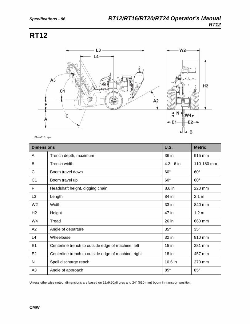
Specifications - 96 RT12/RT16/RT20/RT24 Operator’s ManualRT12
CMW
RT12
Unless otherwise noted, dimensions are based on 18x9.50x8 tires and 24” (610-mm) boom in transport position.
Dimensions U.S. Metric
A Trench depth, maximum 36 in 915 mm
B Trench width 4.3 - 6 in 110-150 mm
C Boom travel down 60° 60°
C1 Boom travel up 60° 60°
F Headshaft height, digging chain 8.6 in 220 mm
L3 Length 84 in 2.1 m
W2 Width 33 in 840 mm
H2 Height 47 in 1.2 m
W4 Tread 26 in 660 mm
A2 Angle of departure 35° 35°
L4 Wheelbase 32 in 810 mm
E1 Centerline trench to outside edge of machine, left 15 in 381 mm
E2 Centerline trench to outside edge of machine, right 18 in 457 mm
N Spoil discharge reach 10.6 in 270 mm
A3 Angle of approach 85° 85°

RT12/RT16/RT20/RT24 Operator’s Manual Specifications - 97RT12
CMW
General
Ditch Witch model RT12, self-propelled, hydrostatic, pedestrian, skid steered, two wheel drive rigid frame, chain type trencher.
Operational U.S. Metric
Vehicle speeds
Equipped with tires:
Maximum transit forward 280 fpm 85.3 m/min
Maximum transit reverse 114 fpm 34.7 m/min
Equipped with wheel tracks:
Maximum transit forward 198 fpm 60 m/min
Maximum transit reverse 97 fpm 29.5 m/min
Digging chain speed:
10 tooth sprocket 324 fpm 98.7 m/min
12 tooth sprocket 389 fpm 118.5 m/min
Spoils handling (single, open-end auger):
Outer diameter 12 in 305 mm
Inner diameter 4 in 102mm
Length 9 in 229 mm
Operating weight (with 33,000-lb [14 969-kg] test, two-pitch digging chain and 24” [610-mm] roller boom)
1020 lb 463 kg
Operating weight (with 35,000-lb [15 876-kg] test, 4.6” [117 mm] Combo Shark digging chain, RotoWitch, backfill blade, tracks and trench cleaner)
1461 lb 664 kg
Power U.S. Metric
Engine: Honda 11.7hp iGX390, gasoline
Cooling medium: air
Number of cylinders: one
Displacement 23.7 in3 389 cm3
Torque @ 2500 rpm 19.5 ft-lb 26.4 N-m
Gross power @ 3600 rpm 11.7 hp 8.7 kW
Rated speed 3600 rpm 3600 rpm

Specifications - 98 RT12/RT16/RT20/RT24 Operator’s ManualRT12
CMW
Maximum tilt angle* 20° 20°
*Exceeding these operational angles will cause engine damage. This DOES NOT IMPLY machine is stable to maximum angle of safe engine operation.
Battery
200 CCA, 12V, reserve capacity 32 min
Power Train U.S. Metric
Ground drive transmission: hydrostatic, infinitely variable from zero to maximum, speed and direction controlled with dual levers
Digging chain drive: hydraulic direct drive, lever-operated, one speed forward and reverse
Trencher drive: hydraulic direct drive
Pump drive: direct drive from engine
Spoils handling drive: mechanical, attached to and rotates with headshaft
Tires:
Drive: 18x9.50x8 bar lug 12 psi 83 kPa
Drive: 18x9.50x8 turf NHS 22 psi 152 kPa
Trail: 13x5.00x6
Hydraulic System U.S. Metric
Tandem pump capacity @ 3600 rpm:
To digging drive 7.8 gpm 29.5 L/min
To ground drive 11.4 gpm 43 L/min
Total 19.2 gpm 72.5 L/min
Fluid Capacities U.S. Metric
Hydraulic reservoir 8 gal 30 L
Hydraulic system 8.5 gal 32 L
Fuel tank 1.7 gal 6.4 L
Engine oil 1.6 qt 1.1 L
Noise Levels
Operator ear 90 dBA sound pressure per ISO 6394
Exterior 102 dBA sound power per ISO 6393
Power U.S. Metric

RT12/RT16/RT20/RT24 Operator’s Manual Specifications - 99RT12
CMW
Vibration Levels
Vibration at the operator’s hand during normal operation is 6.639 m/s2
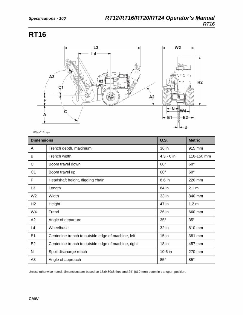
Specifications - 100 RT12/RT16/RT20/RT24 Operator’s ManualRT16
CMW
RT16
Unless otherwise noted, dimensions are based on 18x9.50x8 tires and 24” (610-mm) boom in transport position.
Dimensions U.S. Metric
A Trench depth, maximum 36 in 915 mm
B Trench width 4.3 - 6 in 110-150 mm
C Boom travel down 60° 60°
C1 Boom travel up 60° 60°
F Headshaft height, digging chain 8.6 in 220 mm
L3 Length 84 in 2.1 m
W2 Width 33 in 840 mm
H2 Height 47 in 1.2 m
W4 Tread 26 in 660 mm
A2 Angle of departure 35° 35°
L4 Wheelbase 32 in 810 mm
E1 Centerline trench to outside edge of machine, left 15 in 381 mm
E2 Centerline trench to outside edge of machine, right 18 in 457 mm
N Spoil discharge reach 10.6 in 270 mm
A3 Angle of approach 85° 85°

RT12/RT16/RT20/RT24 Operator’s Manual Specifications - 101RT16
CMW
General
Ditch Witch model RT16, self-propelled, hydrostatic, pedestrian, skid steered, two wheel drive rigid frame, chain type trencher.
Operational U.S. Metric
Vehicle speeds
Equipped with tires:
Maximum transit forward 280 fpm 85.3 m/min
Maximum transit reverse 114 fpm 34.7 m/min
Equipped with wheel tracks:
Maximum transit forward 198 fpm 60 m/min
Maximum transit reverse 97 fpm 29.5 m/min
Digging chain speed:
10 tooth sprocket 324 fpm 98.7 m/min
12 tooth sprocket 389 fpm 118.5 m/min
Spoils handling (single, open-end auger):
Outer diameter 12 in 305 mm
Inner diameter 4 in 102mm
Length 9 in 229 mm
Operating weight (with 33,000-lb [14 969-kg] test, 4.4” [112 mm] four-pitch digging chain and 24” [610-mm] roller boom)
962 lb 437 kg
Operating weight (with 35,000-lb [15 876-kg] test, 4.6” [117 mm] Combo Shark digging chain, RotoWitch, backfill blade, tracks and trench cleaner)
1461 lb 664 kg
Power U.S. Metric
Engine: Briggs & Stratton VanguardTM V-Twin 4 stroke overhead valve
Fuel: gasoline
Cooling medium: air
Number of cylinders: two
Displacement 29.23 in3 479 cm3
Bore 2.68 in 68 mm
Stroke 2.60 in 66 mm
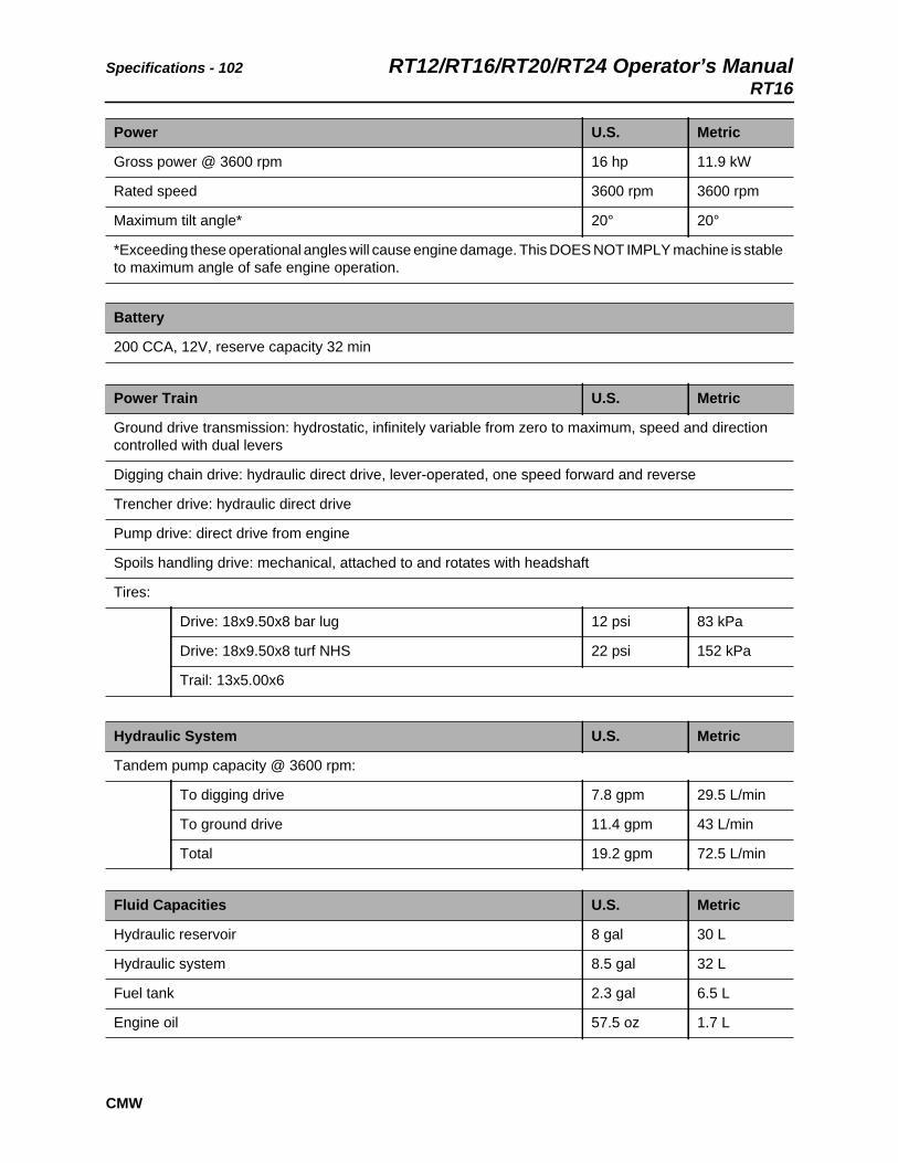
Specifications - 102 RT12/RT16/RT20/RT24 Operator’s ManualRT16
CMW
Gross power @ 3600 rpm 16 hp 11.9 kW
Rated speed 3600 rpm 3600 rpm
Maximum tilt angle* 20° 20°
*Exceeding these operational angles will cause engine damage. This DOES NOT IMPLY machine is stable to maximum angle of safe engine operation.
Battery
200 CCA, 12V, reserve capacity 32 min
Power Train U.S. Metric
Ground drive transmission: hydrostatic, infinitely variable from zero to maximum, speed and direction controlled with dual levers
Digging chain drive: hydraulic direct drive, lever-operated, one speed forward and reverse
Trencher drive: hydraulic direct drive
Pump drive: direct drive from engine
Spoils handling drive: mechanical, attached to and rotates with headshaft
Tires:
Drive: 18x9.50x8 bar lug 12 psi 83 kPa
Drive: 18x9.50x8 turf NHS 22 psi 152 kPa
Trail: 13x5.00x6
Hydraulic System U.S. Metric
Tandem pump capacity @ 3600 rpm:
To digging drive 7.8 gpm 29.5 L/min
To ground drive 11.4 gpm 43 L/min
Total 19.2 gpm 72.5 L/min
Fluid Capacities U.S. Metric
Hydraulic reservoir 8 gal 30 L
Hydraulic system 8.5 gal 32 L
Fuel tank 2.3 gal 6.5 L
Engine oil 57.5 oz 1.7 L
Power U.S. Metric
RT12/RT16/RT20/RT24 Operator’s Manual Specifications - 103RT16
CMW
Noise Levels
Operator 96 dBA sound pressure per ISO 6394
Exterior 100 dBA sound power per ISO 6393
Vibration Levels
Vibration at the operator’s hand during normal operation is 3.387 m/s2
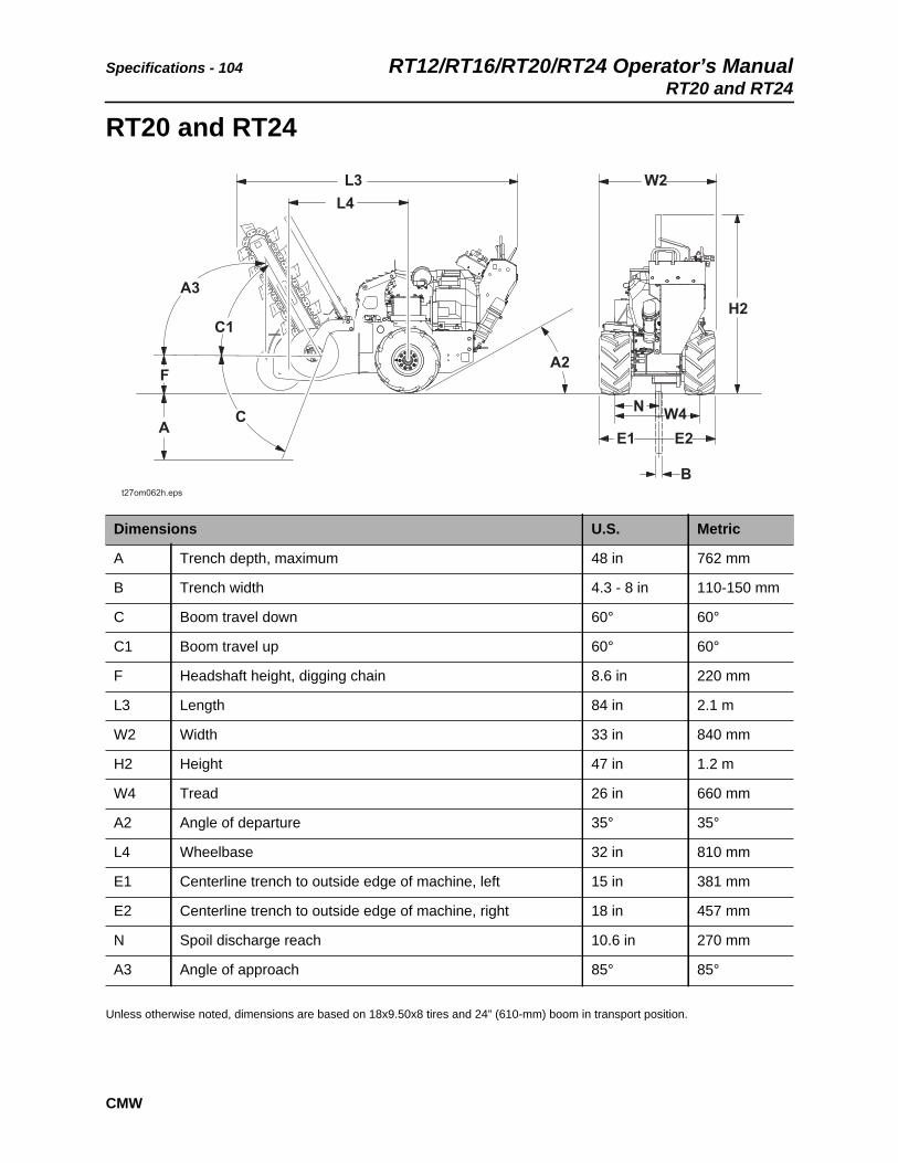
Specifications - 104 RT12/RT16/RT20/RT24 Operator’s ManualRT20 and RT24
CMW
RT20 and RT24
Unless otherwise noted, dimensions are based on 18x9.50x8 tires and 24” (610-mm) boom in transport position.
Dimensions U.S. Metric
A Trench depth, maximum 48 in 762 mm
B Trench width 4.3 - 8 in 110-150 mm
C Boom travel down 60° 60°
C1 Boom travel up 60° 60°
F Headshaft height, digging chain 8.6 in 220 mm
L3 Length 84 in 2.1 m
W2 Width 33 in 840 mm
H2 Height 47 in 1.2 m
W4 Tread 26 in 660 mm
A2 Angle of departure 35° 35°
L4 Wheelbase 32 in 810 mm
E1 Centerline trench to outside edge of machine, left 15 in 381 mm
E2 Centerline trench to outside edge of machine, right 18 in 457 mm
N Spoil discharge reach 10.6 in 270 mm
A3 Angle of approach 85° 85°

RT12/RT16/RT20/RT24 Operator’s Manual Specifications - 105RT20 and RT24
CMW
General
Ditch Witch model RT24, self-propelled, hydrostatic, pedestrian, skid steered, two-wheel drive, rigid frame, chain-type trencher.
Operational U.S. Metric
Vehicle speeds
Equipped with 18” tires:
Maximum transit forward 243 fpm 74 m/min
Maximum transit reverse 97 fpm 30 m/min
Equipped with tracks:
Maximum transit forward 169 fpm 51 m/min
Maximum transit reverse 68 fpm 21 m/min
Digging chain speed at 3600 rpm 420 fpm 12/m/min
Spoils handling (single, open-end auger):
Outer diameter 17 in 432 mm
Inner diameter 4 in 101 mm
Length 8.75 in 222 mm
Operating weight, maximum (with 33,000-lb [14 969-kg] test, 8” two-pitch cup-tooth digging chain on 48” boom, RotoWitch, backfill blade, 3 tower weights, tracks, trench cleaner, and low frame weight)
1601 lb 726 kg
Operating weight, minimum (with 33,000-lb [14 969-kg] test, 4.4” two-pitch digging chain on 24” roller boom, and 18” tires)
1079 lb 489 kg
Power U.S. Metric
RT20 Engine: Honda GX630RT24Engine: Honda GX690
Fuel: gasoline
Cooling medium: air
Number of cylinders: two
Displacement 42 in3 688 cm3
Bore 3.1 in 78 mm
Stroke 2.8 in 72 mm
RT24: Manufacturer’s net power rating 22.3 hp 16.6 kW
RT20: Manufacturer’s net power rating 20.8 hp 15.5 kW
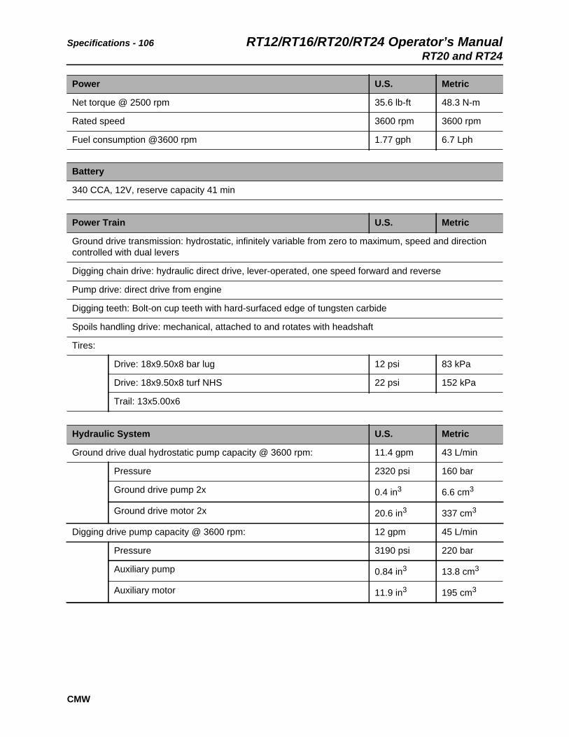
Specifications - 106 RT12/RT16/RT20/RT24 Operator’s ManualRT20 and RT24
CMW
Net torque @ 2500 rpm 35.6 lb-ft 48.3 N-m
Rated speed 3600 rpm 3600 rpm
Fuel consumption @3600 rpm 1.77 gph 6.7 Lph
Battery
340 CCA, 12V, reserve capacity 41 min
Power Train U.S. Metric
Ground drive transmission: hydrostatic, infinitely variable from zero to maximum, speed and direction controlled with dual levers
Digging chain drive: hydraulic direct drive, lever-operated, one speed forward and reverse
Pump drive: direct drive from engine
Digging teeth: Bolt-on cup teeth with hard-surfaced edge of tungsten carbide
Spoils handling drive: mechanical, attached to and rotates with headshaft
Tires:
Drive: 18x9.50x8 bar lug 12 psi 83 kPa
Drive: 18x9.50x8 turf NHS 22 psi 152 kPa
Trail: 13x5.00x6
Hydraulic System U.S. Metric
Ground drive dual hydrostatic pump capacity @ 3600 rpm: 11.4 gpm 43 L/min
Pressure 2320 psi 160 bar
Ground drive pump 2x 0.4 in3 6.6 cm3
Ground drive motor 2x 20.6 in3 337 cm3
Digging drive pump capacity @ 3600 rpm: 12 gpm 45 L/min
Pressure 3190 psi 220 bar
Auxiliary pump 0.84 in3 13.8 cm3
Auxiliary motor 11.9 in3 195 cm3
Power U.S. Metric

RT12/RT16/RT20/RT24 Operator’s Manual Specifications - 107RT20 and RT24
CMW
Fluid Capacities U.S. Metric
Hydraulic reservoir 8 gal 30 L
Hydraulic system 8.5 gal 32 L
Fuel tank 3.5 gal 13 L
Engine oil 2.10 qts 1.99 L
Noise Levels
Operator 93 dBA sound pressure per ISO 6394
Exterior 102 dBA sound power per ISO 6393
Vibration Levels
Vibration at the operator’s hand during normal operation is 5.82 m/s2

Specifications - 108 RT12/RT16/RT20/RT24 Operator’s ManualRT20 and RT24
CMW

RT12/RT16/RT20/RT24 Operator’s Manual Support - 109Procedure
CMW
Support
ProcedureNotify your dealer immediately of any malfunction or failure of Ditch Witch equipment.
Always give model, serial number, and approximate date of your equipment purchase. This information should be recorded and placed on file by the owner at the time of purchase.
Return damaged parts to dealer for inspection and warranty consideration if in warranty time frame.
Order genuine Ditch Witch replacement or repair parts from your authorized Ditch Witch dealer. Use of another manufacturer's parts may void warranty consideration.
Resources
Publications
Contact your Ditch Witch dealer for publications and videos covering safety, operation, service, and repair of your equipment.
Ditch Witch Training
For information about on-site, individualized training, contact your Ditch Witch dealer.

Warranty - 110 RT12/RT16/RT20/RT24 Operator’s Manual
CMW
Warranty
Ditch Witch Equipment and Replacement PartsLimited Warranty Policy
Subject to the limitation and exclusions herein, free replacement parts will be provided at any authorized Ditch Witch dealership for any Ditch Witch equipment or parts manufactured by The Charles Machine Works, Inc. (CMW) that fail due to a defect in material or workmanship within one (1) year of first commercial use (Exception: 2 years for all SK5 attachments). Free labor will be provided at any authorized Ditch Witch dealership for installation of parts under this warranty during the first year following “initial commercial” use of the serial-numbered Ditch Witch equipment on which it is installed. The customer is responsible for transporting their equipment to an authorized Ditch Witch dealership for all warranty work.
Exclusions from Product Warranty• All incidental or consequential damages.
• All defects, damages, or injuries caused by misuse, abuse, improper installation, alteration, neglect, or uses other than those for which products were intended.
• All defects, damages, or injuries caused by improper training, operation, or servicing of products in a manner inconsistent with manufacturer’s recommendations.
• All engines and engine accessories (these are covered by original manufacturer’s warranty).
• Tires, belts, and other parts which may be subject to another manufacturer’s warranty (such warranty will be available to purchaser).
• ALL IMPLIED WARRANTIES NOT EXPRESSLY STATED HEREIN, INCLUDING ANY WARRANTY OF FITNESS FOR A PARTICULAR PURPOSE AND MERCHANTABILITY.
IF THE PRODUCTS ARE PURCHASED FOR COMMERCIAL PURPOSES, AS DEFINED BY THE UNIFORM COMMERCIAL CODE, THEN THERE ARE NO WARRANTIES WHICH EXTEND BEYOND THE FACE HEREOF AND THERE ARE NO IMPLIED WARRANTIES OF ANY KIND WHICH EXTEND TO A COMMERCIAL BUYER. ALL OTHER PROVISIONS OF THIS LIMITED WARRANTY APPLY INCLUDING THE DUTIES IMPOSED.
Ditch Witch products have been tested to deliver acceptable performance in most conditions. This does not imply they will deliver acceptable performance in all conditions. Therefore, to assure suitability, products should be operated under anticipated working conditions prior to purchase.
Defects will be determined by an inspection within thirty (30) days of the date of failure of the product or part by CMW or its authorized dealer. CMW will provide the location of its inspection facilities or its nearest authorized dealer upon inquiry. CMW reserves the right to supply remanufactured replacements parts under this warranty as it deems appropriate.
Extended warranties are available upon request from your local Ditch Witch dealer or CMW.
Some states do not allow exclusion or limitation of incidental or consequential damages, so above limitation of exclusion may not apply. Further, some states do not allow exclusion of or limitation of how long an implied warranty lasts, so the above limitation may not apply. This limited warranty gives product owner specific legal rights and the product owner may also have other rights which vary from state to state.
For information regarding this limited warranty, contact CMW’s Product Support department, P.O. Box 66, Perry, OK 73077-0066, or contact your local Ditch Witch dealer.
First version: 1/91; Latest version: 7/05


RT12/RT16/RT20/RT24 Operator’s Manual Service Record - 113
CMW
Service Record
Service Performed Date Hours

CMW
Service Record - 114 RT12/RT16/RT20/RT24 Operator’s Manual
Service Performed Date Hours


