
www.smthelp.comEmail: [email protected]:+86-139 23898396Tel: +86-755-83203237Fax:+86-755-23240492Skype ID: angela7140
Prepare by: Angela Guo
Eyelet Pin InsertEyelet Pin Insert S-7000S-7000
Eyelet Pin InsertEyelet Pin Insert S-7000S-7000
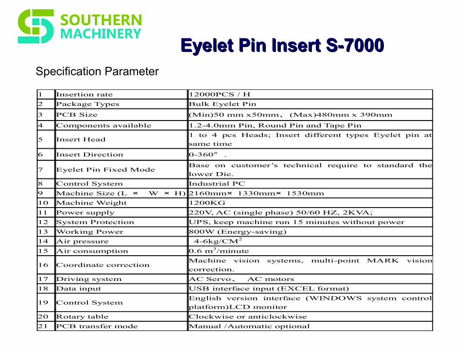
1 Insertion rate 12000PCS / H
2 Package Types Bulk Eyelet Pin
3 PCB Size (Min)50 mm x50mm、(Max)480mm x 390mm
4 Components available 1.2-4.0mm Pin, Round Pin and Tape Pin
5 Insert Head 1 to 4 pcs Heads; Insert different types Eyelet pin at
same time
6 Insert Direction 0-360° .
7 Eyelet Pin Fixed Mode Base on customer’s technical require to standard the
lower Die.
8 Control System Industrial PC
9 Machine Size (L × W × H) 2160mm× 1330mm× 1530mm
10 Machine Weight 1200KG
11 Power supply 220V, AC (single phase) 50/60 HZ, 2KVA;
12 System Protection UPS, keep machine run 15 minutes without power
13 Working Power 800W (Energy-saving)
14 Air pressure 4-6kg/CM2
15 Air consumption 0.6 m3/minute
16 Coordinate correction Machine vision systems, multi-point MARK vision
correction.
17 Driving system AC Servo、 AC motors
18 Data input USB interface input (EXCEL format)
19 Control System English version interface (WINDOWS system control
platform)LCD monitor
20 Rotary table Clockwise or anticlockwise
21 PCB transfer mode Manual /Automatic optional
Specification Parameter
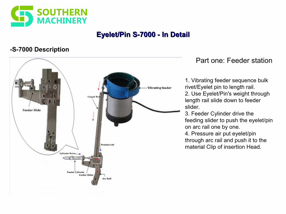
-S-7000 Description
Eyelet/PinEyelet/Pin S-7000S-7000 - In Detail - In Detail
Part one: Feeder station
1. Vibrating feeder sequence bulk rivet/Eyelet pin to length rail.2. Use Eyelet/Pin's weight through length rail slide down to feeder slider.3. Feeder Cylinder drive the feeding slider to push the eyelet/pin on arc rail one by one. 4. Pressure air put eyelet/pin through arc rail and push it to the material Clip of insertion Head.

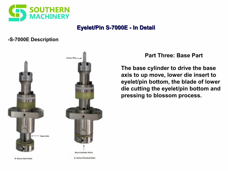
-S-7000E Description
Eyelet/PinEyelet/Pin S-7000ES-7000E - In Detail - In Detail
Part Two: Insertion Part
1. Head Cylinder drive the insertion rod and under pressure, guide pin through eyelet/pin pisitioning.2. Conical part of slide nozzle will push rocker arm with material clamping to opening to both sides, Slide nozzle will press Eyelet/pin to the through hole of PCB.
Eyelet/PinEyelet/Pin S-7000ES-7000E - In Detail - In Detail
-S-7000E Description
Part Three: Base Part
The base cylinder to drive the base axis to up move, lower die insert to eyelet/pin bottom, the blade of lower die cutting the eyelet/pin bottom and pressing to blossom process.
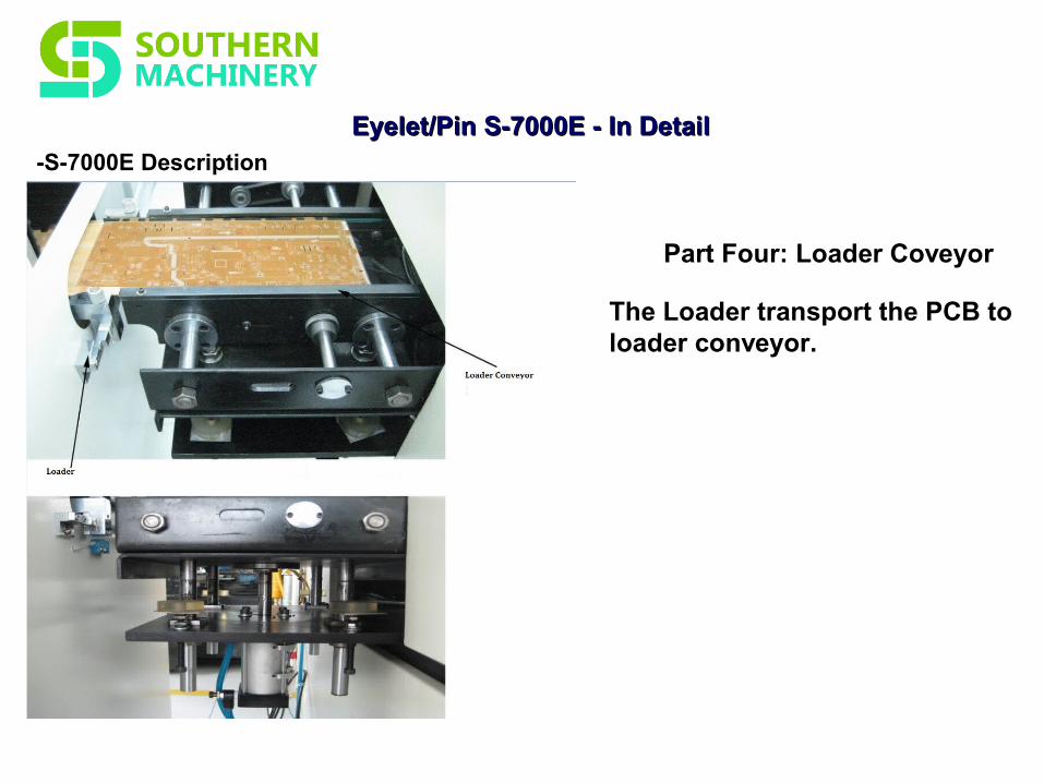
Eyelet/PinEyelet/Pin S-7000ES-7000E - In Detail - In Detail-S-7000E Description
Part Four: Loader Coveyor
The Loader transport the PCB to loader conveyor.
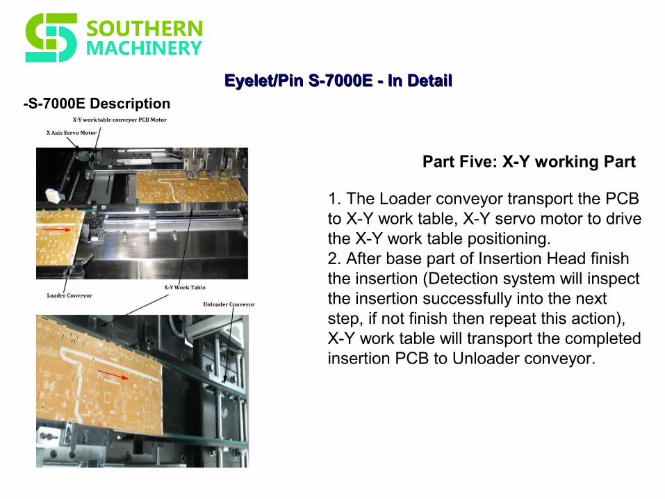
Eyelet/PinEyelet/Pin S-7000ES-7000E - In Detail - In Detail-S-7000E Description
Part Five: X-Y working Part
1. The Loader conveyor transport the PCB to X-Y work table, X-Y servo motor to drive the X-Y work table positioning.2. After base part of Insertion Head finish the insertion (Detection system will inspect the insertion successfully into the next step, if not finish then repeat this action), X-Y work table will transport the completed insertion PCB to Unloader conveyor.
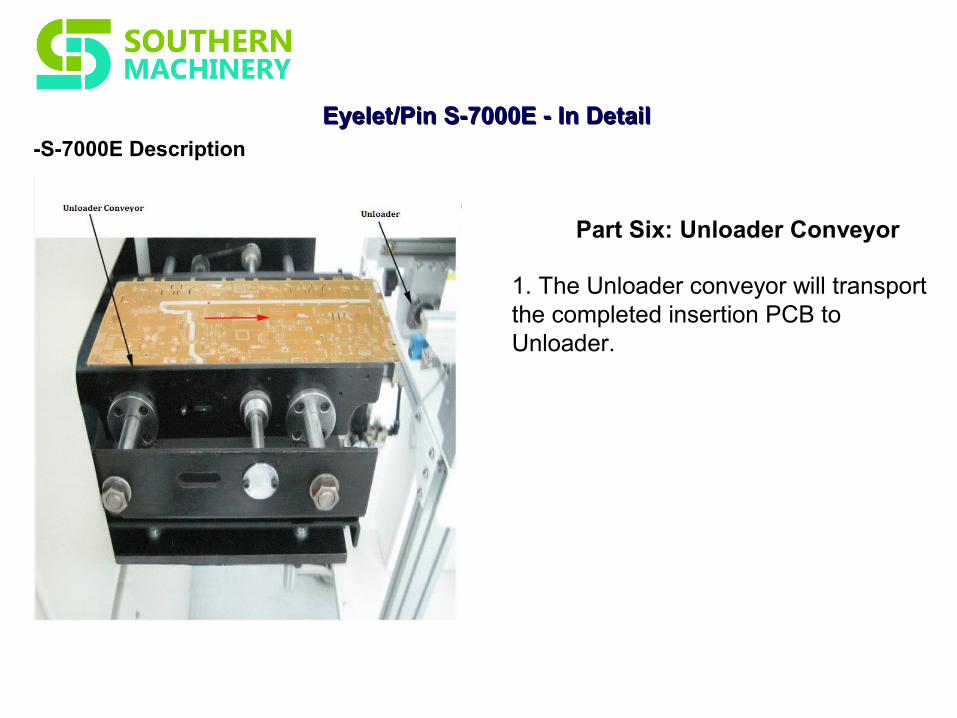
Eyelet/PinEyelet/Pin S-7000ES-7000E - In Detail - In Detail-S-7000E Description
Part Six: Unloader Conveyor
1. The Unloader conveyor will transport the completed insertion PCB to Unloader.

Eyelet/PinEyelet/Pin Insertion PCBInsertion PCB
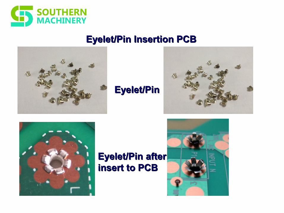
Eyelet/PinEyelet/Pin Insertion PCBInsertion PCB
Eyelet/PinEyelet/Pin
Eyelet/PinEyelet/Pin after after insert to PCBinsert to PCB
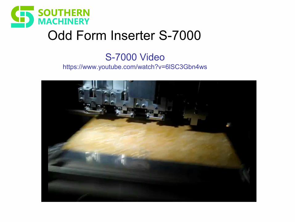
Odd Form Inserter S-7000
S-7000 Videohttps://www.youtube.com/watch?v=6lSC3Gbn4ws
Our customers


