
RANDOM*SOURCE
RANDOMSOURCE.NET 1
Serge NTO
SERGE New Timbral Oscillator (NTO) for Eurorack
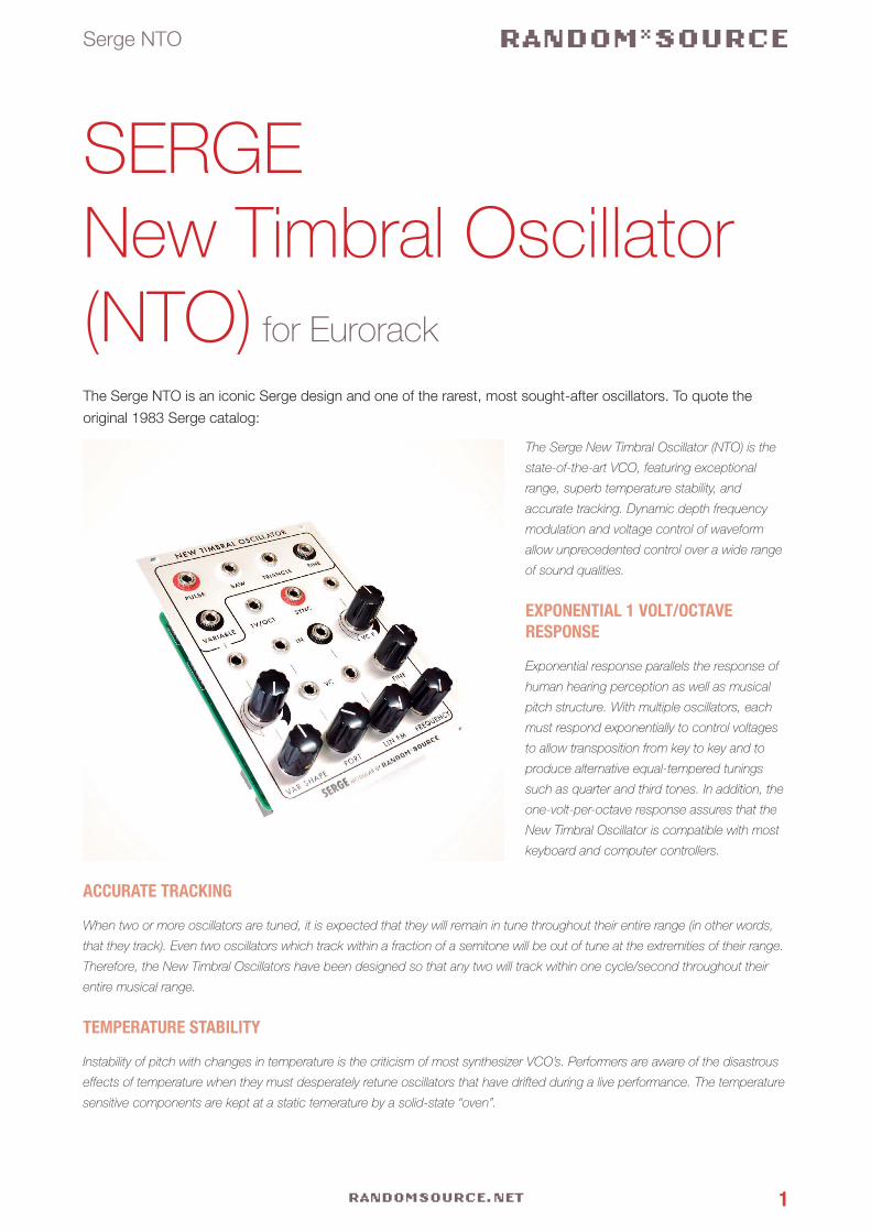
The Serge NTO is an iconic Serge design and one of the rarest, most sought-after oscillators. To quote the
original 1983 Serge catalog:
The Serge New Timbral Oscillator (NTO) is the
state-of-the-art VCO, featuring exceptional
range, superb temperature stability, and
accurate tracking. Dynamic depth frequency
modulation and voltage control of waveform
allow unprecedented control over a wide range
of sound qualities.
EXPONENTIAL 1 VOLT/OCTAVE RESPONSE
Exponential response parallels the response of
human hearing perception as well as musical
pitch structure. With multiple oscillators, each
must respond exponentially to control voltages
to allow transposition from key to key and to
produce alternative equal-tempered tunings
such as quarter and third tones. In addition, the
one-volt-per-octave response assures that the
New Timbral Oscillator is compatible with most
keyboard and computer controllers.
ACCURATE TRACKING
When two or more oscillators are tuned, it is expected that they will remain in tune throughout their entire range (in other words,
that they track). Even two oscillators which track within a fraction of a semitone will be out of tune at the extremities of their range.
Therefore, the New Timbral Oscillators have been designed so that any two will track within one cycle/second throughout their
entire musical range.
TEMPERATURE STABILITY
Instability of pitch with changes in temperature is the criticism of most synthesizer VCO’s. Performers are aware of the disastrous
effects of temperature when they must desperately retune oscillators that have drifted during a live performance. The temperature
sensitive components are kept at a static temerature by a solid-state “oven”.
RANDOM*SOURCE
RANDOMSOURCE.NET 2
Serge NTO
WIDE FREQUENCY RANGE
The frequency range covers from below 16 to 16Khz. With control voltages, the range can be further extended from less than 0.1
Hz (10 sec/cycle) to greater than 100,000 Hz.
VARIETY OF WAVEFORM OUTPUTS
In addition to three standard waveforms (sine, triangle and sawtooth) of exceptional purity, the New Timbral Oscillator offers a
variable waveform output providing an amazingly varied range of sounds, unavailable on any other synthesizer. This waveform is
voltage controllable, allowing dynamic control of sound quality.
DYNAMIC DEPTH LINEAR FREQUENCY MODULATION
Dynamic depth frequency modulation is now available to the analog synthesist. Frequency modulation (FM), the modulation of
one oscillator by another, generates both harmonic overtones (found in most acoustic instrument sounds) and non-harmonic
overtones (bells, percussive, and electronic timbres). By varying the amplitude of the modulating oscillator, the richness or com-
plexity of the sound can be varied. However, with conventional FM, an annoying pitch shift occurs. With the New Timbral Oscilla-
tor, Linear FM avoids this pitch shift, making it possible to maintain accurate pitch control while changing the quality of sound. A
built-in VCA assures accuracy and provides dynamic voltage control of Linear FM Depth. Of course, conventional exponential FM
is also available on the New Timbral Oscillator.
The New Timbral Oscillator offers two voltage control inputs calibrated to one volt per octave and one variable voltage control
input. One of the calibrated inputs incorporates a variable Portamento. This allows gliding from pitch to pitch at a voltage-control-
lable rate, set at each oscillator rather than from the controller (such as a keyboard), and therefore independently variable at each
New Timbral Oscillator. All of the output levels are “hot”, greater than +4 db to ensure maximum signal-to-noise ratio.
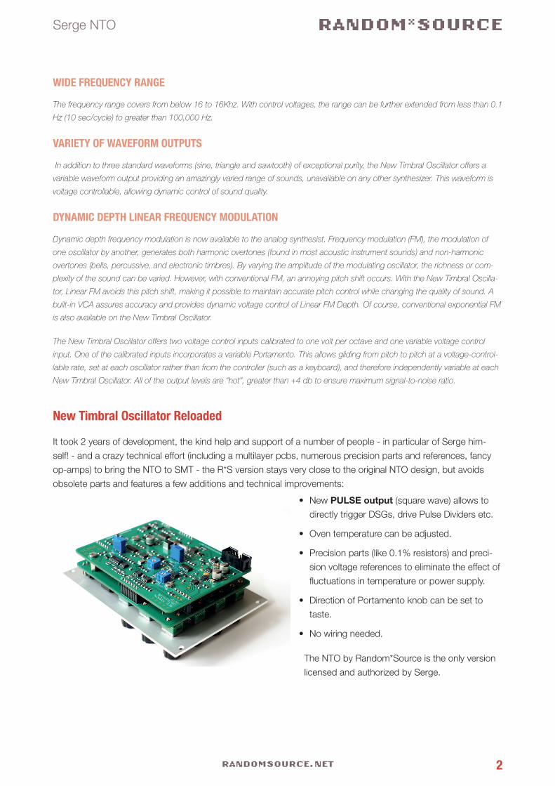
New Timbral Oscillator Reloaded
It took 2 years of development, the kind help and support of a number of people - in particular of Serge him-
self! - and a crazy technical effort (including a multilayer pcbs, numerous precision parts and references, fancy
op-amps) to bring the NTO to SMT - the R*S version stays very close to the original NTO design, but avoids
obsolete parts and features a few additions and technical improvements:
• New PULSE output (square wave) allows to
directly trigger DSGs, drive Pulse Dividers etc.
• Oven temperature can be adjusted.
• Precision parts (like 0.1% resistors) and preci-
sion voltage references to eliminate the effect of
fluctuations in temperature or power supply.
• Direction of Portamento knob can be set to
taste.
• No wiring needed.
The NTO by Random*Source is the only version
licensed and authorized by Serge.
RANDOM*SOURCE
RANDOMSOURCE.NET 3
Serge NTO
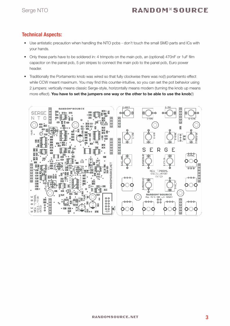
Technical Aspects:• Use antistatic precaution when handling the NTO pcbs - don’t touch the small SMD parts and ICs with
your hands.
• Only these parts have to be soldered in: 4 trimpots on the main pcb, an (optional) 470nF or 1uF film
capacitor on the panel pcb, 5 pin stripes to connect the main pcb to the panel pcb, Euro power
header.
• Traditionally the Portamento knob was wired so that fully clockwise there was no(!) portamento effect
while CCW meant maximum. You may find this counter-intuitive, so you can set the pot behavior using
2 jumpers: vertically means classic Serge-style, horizontally means modern (turning the knob up means
more effect). You have to set the jumpers one way or the other to be able to use the knob(!)
RANDOM*SOURCE
RANDOMSOURCE.NET 4
Serge NTO
Bill of Materials
Trimmers2 20k
(25k also works for
TEMP)
TEMP, HF-COMP
Single-turn recommended
Trimpot (Bourns 3362P, Vishay T73YP203KT20 or
anything that matches the footprint) to adjust the oven
temperature and the high-frequency compensation.
1 100R 1V/Oct
Single- or Multiturn
Trimpot (Bourns 3362P, Vishay T73YP101KT20 or
anything that matches the footprint) to adjust the tra-
cking of the 1V/Oct inputs. I find single turn sufficient.
1 50k FM
Single- or Multiturn
Trimpot (Bourns 3362P or Vishay T73YP503KT20 or
anything that matches the footprint) (see FM Calibra-
tion).
Misc1 470nF Film cap on panel pcb (or 1uF Film), 5mm lead spacing, e.g. WIMA MK2-5
1 Euro Power
connector
MTA-100 power connector, Reichelt: WSL 10G
1
3
1
SIL header 4 pol
SIL header 6 pol
SIL header 7pol
connectors to link main pcb to panel pcb
4
8
10mm standoffs +
matching screws
spacers - hight should match
the SIL headers / connectors
Not absolutely necessary
13 Thonkiconn Jacks 3.5mm Jack Sockets (PJ301M-12) from Thonk
1 Potentionmeter
100k or more
(50k works, too)
linear (B100K, B250K or B500K)
for VC F (Exponential FM)
Alpha 9mm vertical pcb mount -
value determines knob sensitivity in the center
(range is always the same)
6 Potentionmeter
50k or 100k
linear (B50K or B100K) Alpha 9mm vertical pcb mount
available from Thonk, Tayda
RANDOM*SOURCE
RANDOMSOURCE.NET 5
Serge NTO
Building
This is simply a suggestion - you might find a different workflow more practical:
1. Solder the trimmers and the power connector onto the main pcb.
2. Solder the 470nF film cap onto the panel pcb. This capacitor is to remove any DC offsets from the signal
going into the (black) Linear FM input. It is in parallel to a 100n C0G cap already installed (increasing a
470nF cap effectively to 570nF), so even if you do not install the additional film cap, the LIN FM should
still work. The size of this cap (combination) affects the behavior of (very) low frequency signals going in,
however, there is another capacitor later in the audio path, so the effect is limited. Also, for normal audio
rates, it should not make much or any difference, only if you use frequencies like 20Hz. So no need to
worry about the size of this cap much. 470nF should work fine.
3. Solder pins and install 2 jumpers in the middle of the panel pcb setting the direction of the Portamento
knob. Make sure you install the pins on the right side (not where the pots and jacks sit) so that you can
change them without having to unmount the panel pcb.
4. Add spacers / standoffs (10mm) to the panel pcb. Spacers are not really necessary as the connectors
firmly hold the main pcb anyway, but if you choose to add them, this is a good time.
5. Main pcb and panel pcb are to be connected through precision SIP socket and pins. It is recommended
to use the pins on the main pcb (facing down, soldered from above) and the pin sockets on the panel
pcb (standing up, soldered from the front panel side). Break or cut off the pieces you need and stick them
together so that main pcb and component pcb form a nice sandwich (don‘t solder yet). Check that you
didn‘t leave out any pins / holes and that the sockets are all on the same side (panel pcb). Also make sure
the pcbs have the right orientation (so that the pots will sit outside!). Solder all the pins in while keeping
the sandwich together - this avoids any misalignments.
6. Carefully separate the sandwich - if you used precision sockets, this may not to too easy - they stick
together nicely (giving a good connection).
7. Mount the Thonkiconn jacks and the potentiometer onto the panel pcb. Pots should sit on the printed
side - this side faces the front panel. Don‘t solder them in yet.
8. Carefully mount the pcb (with the pots and jacks inserted) onto the front panel. You may then have to
wiggle each pot a bit to get the pots through. Make sure the threads of the pots go through completely
and the pots sit right at the front panel. Screw the jacks and pots onto the panel.
9. Once everything is nicely in place, solder the pots and jacks onto the pcb (while the front panel is at-
tached).
10. Mount the main pcb onto the panel pcb and fasten it using screws / spacers if desired.
11. Connect a power cord supplying +12V, GND, GND, -12V to the power-header on the main board and
double check the direction of the power header before you turn power on. You should be ready to go :-)
RANDOM*SOURCE
RANDOMSOURCE.NET 6
Serge NTO
CalibrationCalibration should be pretty easy if you follow these steps - please beware that tracking is dependent of the
oven temperature, i.e. changing the oven temperature requires (re-)calibration of the 1V/Oct trimmer!
Oven Temperature and Tracking
Connect the SAW output to speakers so you can listen to any changes. Turn the TEMP trimmer all the way
down (i.e. set the temperature as low as possible) - the pitch of the oscillator goes down as you lower the tem-
perature. This base temperature saves energy and should work well in normal (climatic) conditions. The module
will probably draw around 105mA now (depending on environment). Now feed a 1V/Octave signal into one of
the inputs and calibrate the 1V/OCT trimmer. Do not touch the TEMP trimmer again (or you’ll have to calibrate
the 1V/Oct again!).
Beware that changing the 1V/OCT trimmer by nature always affects the pitch: start out with A1, for example,
by playing that note on the keyboard and setting the pitch of the NTO to A1 (using COARSE and FINE knobs).
Then play A2 on the keyboard to see how far off the pitch is (most likely you get a fequency too high or too
low, i.e. the tracking is too steep or not steep enough). If you now change the 1V/OCT trimmer, you will move
A1 away from the pitch you set before at the same time - however, you will increase or decrease the frequency
range that a 1 octave jump in the keyboard (i.e. 1V into the 1V/Oct input) will cause. This is completely normal,
so the goal is to set the trimmer so that the distance is one octave regardless of the pitch. So one approach is
to keep jumping up and down 1 or 2 octaves and adjust the trimmer so that the range gets very close to the
desired 1 or 2 octaves (without worrying about pitch being in tune) - any once that is fairly close to use FINE and
COARSE to set the pitch precisely and then fine-adjust the trimmer for the desired precision.
If you’re obsessed about getting the maximum tracking possible, make sure you have a precision voltage source
(most keyboards are only roughly 1V/Oct - 1 cent corresponds to 1/1200th of a Volt) and that you also have a
very precise frequency counter / tuner - many tuners are not very exact in higher frequencies. However, if you
want to NTO to track over a normal, musically useable range, you should be able to get good results by ear or
with a tuner very quickly.
HF Compensation
The HF trimmer has a very subtle effect on higher frequencies - it will bring up those by a few Hz, which might
be barely audible, so you may not notice its effect unless you have a fairly precise frequency counter. I personally
do not care too much about HF adjustment and noticed that software tuners (e.g. in logic) do not seem to be
able to handle the high frequencies affected by compensation, anyway. So HF trimming is rather optional.
RANDOM*SOURCE
RANDOMSOURCE.NET 7
Serge NTO
FM
Exponential FM is the input in the bottom left corner (with an attenuverter marked “VC F”). This is basically an
(internal) CV processor going into a (hidden) 1V/Oct inout. There is nothing to calibrate here.
Linear FM: Unlike the PCO, the NTO offers voltage control over the LInear FM (this is a unique NTO feature).
The Linear FM section comprises the 2 jacks above the LIN FM knob. Input is the top (black) jack underneath
the 1V/Oct in the center, VC input is the jack below. The FM trimmer on the pcb eliminates bleeding of a CV sig-
nal for the LIN FM section. To calibrate, feed a signal at audio range into the white VC input (middle jack) for
LIN FM without any audio (FM input) signal going into the black input above and listen to the SAW output (pitch
of the VCO). Adjust the trimmer so that the effect of the CV signal is as little as possible.
Power Consumption
Depending on the oven setting (and environmental temperature), the NTO draws about 95mA to 115mA.
Please note that a good power supply is essential for VCO performance.
(Last Change: 14. May 2017, 3:58 PM)
SERGE Modular by Random*Source. Module and circuit under license from Serge Tcherepnin. All rights reserved.


