
www.saihyd.com [email protected]
Crankshaft DesignRadial Piston Hydraulic Motors
GM SERIESTECHNICAL CATALOG
CONTENTS PAGE
Motor Displacement Table 2
Motor Characteristics & Technical Data 3
GM05 Series 9
GM1 Series 13
GM2 Series 17
GM3/GM3A Series 21
GM4 Series 25
GM5A Series 29
GM6 Series 33
L7 Series 37
MOTOR - GEARBOX COMBINATION
GR Series 41
DISTRIBUTORS & SAE FLANGES
Distributor Valves 46
SAE Flanges 52
REVA090102ED5
2
GM
��� ��������� ��� ��� ��� ��� ��� ��� ���
������ ��� �� � ���� ���� ���� ����� ����� ����� ����� �����
������� ���� �� ���� ���� ���� ���� ���� ���� ����
��� ����� � ���� ���� ���� ���� ���� ��� ���
�� ! ���� �� �� �� �� �� �� �� ��
��� ��������� ��� �� ��� �� ��� ��� ��� ����
������ ��� �� � ���� ����� ����� ����� ����� ����� ����� ����� �����
������� ���� �� ���� ���� ���� ���� ���� ���� ���� ����
��� ����� � ��� ��� ��� ��� ��� ��� ��� ���
�� ! ���� �� ��� ��� ��� ��� ��� ��� ��� ���
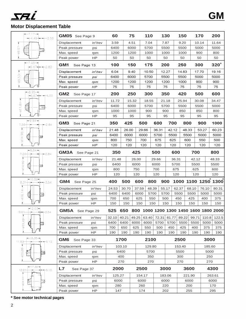
Motor Displacement Table
A3MG 12egaPeeS 053 524 005 006 007 008
tnemecalpsiD ni 3 ver/ 84.12 00.62 66.92 13.63 21.24 33.84
erusserpkaeP isp 0046 0006 0006 0075 0055 0055
deeps.xaM mpr 008 057 007 576 526 006
rewopkaeP PH 021 021 021 021 021 021
4MG 52egaPeeS 004 005 006 008 009 0001 0011 0521 0031
tnemecalpsiD ni 3 ver/ 35.42 07.03 95.73 93.84 71.55 73.26 01.86 01.67 13.08
erusserpkaeP isp 0046 0046 0006 0075 0075 0055 0055 0005 0005
deeps.xaM mpr 007 056 526 055 005 054 524 004 573
rewopkaeP PH 051 051 051 051 051 051 051 051 051
A5MG 92egaPeeS 525 056 008 0001 0021 0031 0541 0061 0081 0002
tnemecalpsiD ni 3 ver/ 01.23 12.04 52.94 04.36 13.27 77.18 22.98 17.99 8.011 5.221
erusserpkaeP isp 0046 0046 0006 0006 0075 0075 0055 0055 0005 0005
deeps.xaM mpr 007 056 526 055 005 054 524 004 573 573
rewopkaeP PH 091 091 091 091 091 091 091 091 091 091
6MG 33egaPeeS 0071 0012 0052 0003
tnemecalpsiD ni 3 ver/ 01.301 08.921 04.351 06.581
erusserpkaeP isp 0046 0075 0055 0005
deeps.xaM mpr 004 053 003 052
rewopkaeP PH 072 072 072 072
7L 73egaPeeS 0002 0052 0003 0063 0034
tnemecalpsiD ni 3 ver/ 72.521 71.451 60.381 09.122 16.362
erusserpkaeP isp 0006 0006 0006 0006 0006
deeps.xaM mpr 082 062 022 002 071
rewopkaeP PH 741 471 202 552 592
50MG 9egaPeeS 06 57 011 031 051 071 002
tnemecalpsiD ni 3 ver/ 95.3 15.4 40.7 78.7 02.9 41.01 46.11
erusserpkaeP isp 0046 0006 0075 0055 0055 0005 0005
deeps.xaM mpr 0021 0021 0001 0001 0001 009 008
rewopkaeP PH 05 05 05 05 05 05 05
2MG 71egaPeeS 002 052 003 053 024 005 006
tnemecalpsiD ni 3 ver/ 27.11 23.51 55.81 81.12 49.52 80.03 74.43
erusserpkaeP isp 0046 0006 0075 0075 0055 0055 0005
deeps.xaM mpr 0001 0001 009 009 058 058 008
rewopkaeP PH 59 59 59 59 59 59 59
*
* *
* See motor technical pages
3
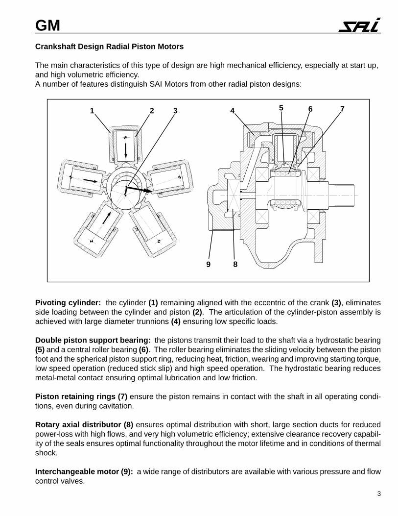
GMCrankshaft Design Radial Piston Motors
The main characteristics of this type of design are high mechanical efficiency, especially at start up,and high volumetric efficiency.A number of features distinguish SAI Motors from other radial piston designs:
Pivoting cylinder: the cylinder (1) remaining aligned with the eccentric of the crank (3), eliminatesside loading between the cylinder and piston (2). The articulation of the cylinder-piston assembly isachieved with large diameter trunnions (4) ensuring low specific loads.
Double piston support bearing: the pistons transmit their load to the shaft via a hydrostatic bearing(5) and a central roller bearing (6). The roller bearing eliminates the sliding velocity between the pistonfoot and the spherical piston support ring, reducing heat, friction, wearing and improving starting torque,low speed operation (reduced stick slip) and high speed operation. The hydrostatic bearing reducesmetal-metal contact ensuring optimal lubrication and low friction.
Piston retaining rings (7) ensure the piston remains in contact with the shaft in all operating condi-tions, even during cavitation.
Rotary axial distributor (8) ensures optimal distribution with short, large section ducts for reducedpower-loss with high flows, and very high volumetric efficiency; extensive clearance recovery capabil-ity of the seals ensures optimal functionality throughout the motor lifetime and in conditions of thermalshock.
Interchangeable motor (9): a wide range of distributors are available with various pressure and flowcontrol valves.
1 32 4 5 6 7
89
4
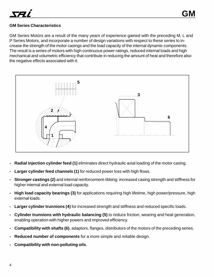
GMGM Series Characteristics
GM Series Motors are a result of the many years of experience gained with the preceding M, L andP Series Motors, and incorporate a number of design variations with respect to these series to in-crease the strength of the motor casings and the load capacity of the internal dynamic components.The result is a series of motors with high continuous power ratings, reduced internal loads and highmechanical and volumetric efficiency that contribute in reducing the amount of heat and therefore alsothe negative effects associated with it.
- Radial injection cylinder feed (1) eliminates direct hydraulic axial loading of the motor casing.
- Larger cylinder feed channels (1) for reduced power loss with high flows.
- Stronger castings (2) and internal reinforcement ribbing: increased casing strength and stiffness forhigher internal and external load capacity.
- High load capacity bearings (3) for applications requiring high lifetime, high power/pressure, highexternal loads.
- Larger cylinder trunnions (4) for increased strength and stiffness and reduced specific loads.
- Cylinder trunnions with hydraulic balancing (5) to reduce friction, wearing and heat generation,enabling operation with higher powers and improved efficiency.
- Compatibility with shafts (6), adaptors, flanges, distributors of the motors of the preceding series.
- Reduced number of components for a more simple and reliable design.
- Compatibility with non-polluting oils.
1
2
3
4
5
6
5
GMPRESSURE RATINGSAll the motors are rated at a nominal continuous pressurerating of 3,650 psi. The continuous and average operatingpressure, however, should be chosen in function of the re-quired bearing lifetime (see bearing lifetime graphs).The peak operating pressures are given in the relativedisplacement tables. The motors may work at peak pres-sures for periods not exceeding 1% per minute, no morethan 10 times per hour.
BACK-PRESSUREThe motors are capable of operating with high back-pres-sures with high efficiency, e.g. for series circuit applica-tions.The allowable pressures vary in function piston diameterand other factors. If the motors are required for an appli-cation with back pressure contact the technical depart-ment for further details.Typical allowable back-pressure
Port A Port BCont. 3,000 psi 2,200 psiPeak 5,000 psi 5,000 psi
CASE PRESSUREContinuous case pressure: 15 psiPeak case pressure: 75 psiThe case pressure is independent of the return line pres-sure.For higher pressures (up to 350 psi) contact the technicaldepartment.
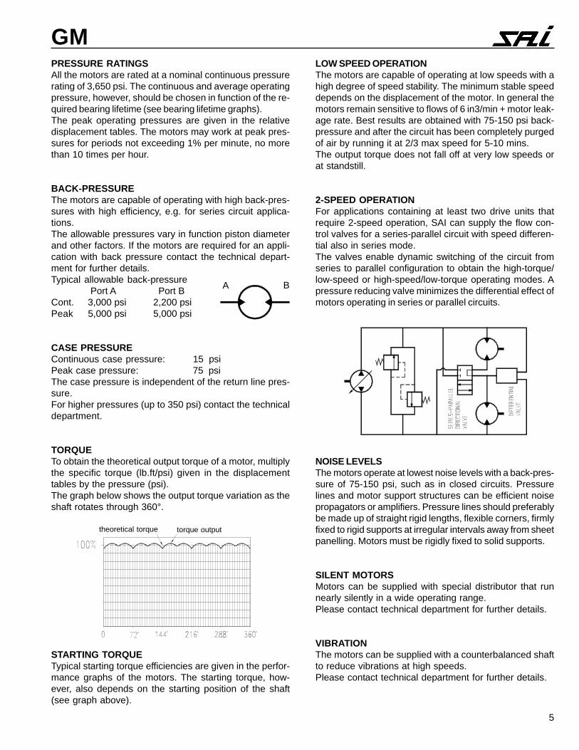
TORQUETo obtain the theoretical output torque of a motor, multiplythe specific torque (lb.ft/psi) given in the displacementtables by the pressure (psi).The graph below shows the output torque variation as theshaft rotates through 360°.
STARTING TORQUETypical starting torque efficiencies are given in the perfor-mance graphs of the motors. The starting torque, how-ever, also depends on the starting position of the shaft(see graph above).
theoretical torque torque output
LOW SPEED OPERATIONThe motors are capable of operating at low speeds with ahigh degree of speed stability. The minimum stable speeddepends on the displacement of the motor. In general themotors remain sensitive to flows of 6 in3/min + motor leak-age rate. Best results are obtained with 75-150 psi back-pressure and after the circuit has been completely purgedof air by running it at 2/3 max speed for 5-10 mins.The output torque does not fall off at very low speeds orat standstill.
2-SPEED OPERATIONFor applications containing at least two drive units thatrequire 2-speed operation, SAI can supply the flow con-trol valves for a series-parallel circuit with speed differen-tial also in series mode.The valves enable dynamic switching of the circuit fromseries to parallel configuration to obtain the high-torque/low-speed or high-speed/low-torque operating modes. Apressure reducing valve minimizes the differential effect ofmotors operating in series or parallel circuits.
NOISE LEVELSThe motors operate at lowest noise levels with a back-pres-sure of 75-150 psi, such as in closed circuits. Pressurelines and motor support structures can be efficient noisepropagators or amplifiers. Pressure lines should preferablybe made up of straight rigid lengths, flexible corners, firmlyfixed to rigid supports at irregular intervals away from sheetpanelling. Motors must be rigidly fixed to solid supports.
SILENT MOTORSMotors can be supplied with special distributor that runnearly silently in a wide operating range.Please contact technical department for further details.
VIBRATIONThe motors can be supplied with a counterbalanced shaftto reduce vibrations at high speeds.Please contact technical department for further details.
A B
6
GMCAVITATIONThe design of the motors ensures they are not damagedif subjected to cavitation, even for prolonged periods oftime.The motors will rotate normally even with empty cylinders(i.e. no oil - air, or vacuum), which is useful for disconnect-ing the motor from the hydraulic circuit (see below).
OPERATION IN FREEWHEELING AND AS HYDRAULICBRAKETransitions from normal motor operating mode to free-wheeling and hydraulic braking mode can be carried outdynamically.
DISCONNECTION FROM HYDRAULIC CIRCUITThe motors can be disconnected from the hydraulic anddriven externally (freewheeling, free fall, in case of break-down, etc.) at speeds of up to the max. speeds given.For higher speeds please contact our technical office.
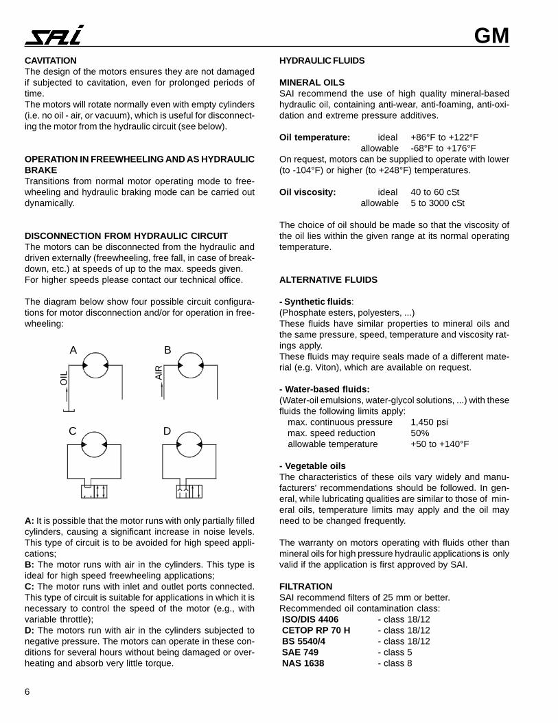
The diagram below show four possible circuit configura-tions for motor disconnection and/or for operation in free-wheeling:
A: It is possible that the motor runs with only partially filledcylinders, causing a significant increase in noise levels.This type of circuit is to be avoided for high speed appli-cations;B: The motor runs with air in the cylinders. This type isideal for high speed freewheeling applications;C: The motor runs with inlet and outlet ports connected.This type of circuit is suitable for applications in which it isnecessary to control the speed of the motor (e.g., withvariable throttle);D: The motors run with air in the cylinders subjected tonegative pressure. The motors can operate in these con-ditions for several hours without being damaged or over-heating and absorb very little torque.
HYDRAULIC FLUIDS
MINERAL OILSSAI recommend the use of high quality mineral-basedhydraulic oil, containing anti-wear, anti-foaming, anti-oxi-dation and extreme pressure additives.
Oil temperature: ideal +86°F to +122°F allowable -68°F to +176°F
On request, motors can be supplied to operate with lower(to -104°F) or higher (to +248°F) temperatures.
Oil viscosity: ideal 40 to 60 cSt allowable 5 to 3000 cSt
The choice of oil should be made so that the viscosity ofthe oil lies within the given range at its normal operatingtemperature.
ALTERNATIVE FLUIDS
- Synthetic fluids:(Phosphate esters, polyesters, ...)These fluids have similar properties to mineral oils andthe same pressure, speed, temperature and viscosity rat-ings apply.These fluids may require seals made of a different mate-rial (e.g. Viton), which are available on request.
- Water-based fluids:(Water-oil emulsions, water-glycol solutions, ...) with thesefluids the following limits apply: max. continuous pressure 1,450 psi max. speed reduction 50% allowable temperature +50 to +140°F
- Vegetable oilsThe characteristics of these oils vary widely and manu-facturers' recommendations should be followed. In gen-eral, while lubricating qualities are similar to those of min-eral oils, temperature limits may apply and the oil mayneed to be changed frequently.
The warranty on motors operating with fluids other thanmineral oils for high pressure hydraulic applications is onlyvalid if the application is first approved by SAI.
FILTRATIONSAI recommend filters of 25 mm or better.Recommended oil contamination class: ISO/DIS 4406 - class 18/12 CETOP RP 70 H - class 18/12 BS 5540/4 - class 18/12 SAE 749 - class 5 NAS 1638 - class 8
A B
C D
OIL AIR
7
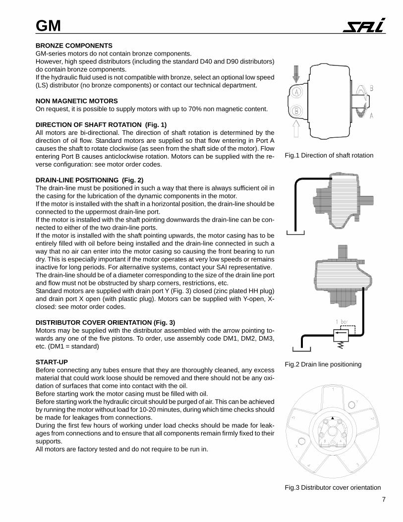
GMBRONZE COMPONENTSGM-series motors do not contain bronze components.However, high speed distributors (including the standard D40 and D90 distributors)do contain bronze components.If the hydraulic fluid used is not compatible with bronze, select an optional low speed(LS) distributor (no bronze components) or contact our technical department.
NON MAGNETIC MOTORSOn request, it is possible to supply motors with up to 70% non magnetic content.
DIRECTION OF SHAFT ROTATION (Fig. 1)All motors are bi-directional. The direction of shaft rotation is determined by thedirection of oil flow. Standard motors are supplied so that flow entering in Port Acauses the shaft to rotate clockwise (as seen from the shaft side of the motor). Flowentering Port B causes anticlockwise rotation. Motors can be supplied with the re-verse configuration: see motor order codes.
DRAIN-LINE POSITIONING (Fig. 2)The drain-line must be positioned in such a way that there is always sufficient oil inthe casing for the lubrication of the dynamic components in the motor.If the motor is installed with the shaft in a horizontal position, the drain-line should beconnected to the uppermost drain-line port.If the motor is installed with the shaft pointing downwards the drain-line can be con-nected to either of the two drain-line ports.If the motor is installed with the shaft pointing upwards, the motor casing has to beentirely filled with oil before being installed and the drain-line connected in such away that no air can enter into the motor casing so causing the front bearing to rundry. This is especially important if the motor operates at very low speeds or remainsinactive for long periods. For alternative systems, contact your SAI representative.The drain-line should be of a diameter corresponding to the size of the drain line portand flow must not be obstructed by sharp corners, restrictions, etc.Standard motors are supplied with drain port Y (Fig. 3) closed (zinc plated HH plug)and drain port X open (with plastic plug). Motors can be supplied with Y-open, X-closed: see motor order codes.
DISTRIBUTOR COVER ORIENTATION (Fig. 3)Motors may be supplied with the distributor assembled with the arrow pointing to-wards any one of the five pistons. To order, use assembly code DM1, DM2, DM3,etc. (DM1 = standard)
START-UPBefore connecting any tubes ensure that they are thoroughly cleaned, any excessmaterial that could work loose should be removed and there should not be any oxi-dation of surfaces that come into contact with the oil.Before starting work the motor casing must be filled with oil.Before starting work the hydraulic circuit should be purged of air. This can be achievedby running the motor without load for 10-20 minutes, during which time checks shouldbe made for leakages from connections.During the first few hours of working under load checks should be made for leak-ages from connections and to ensure that all components remain firmly fixed to theirsupports.All motors are factory tested and do not require to be run in.
Fig.1 Direction of shaft rotation
Fig.2 Drain line positioning
Fig.3 Distributor cover orientation
8
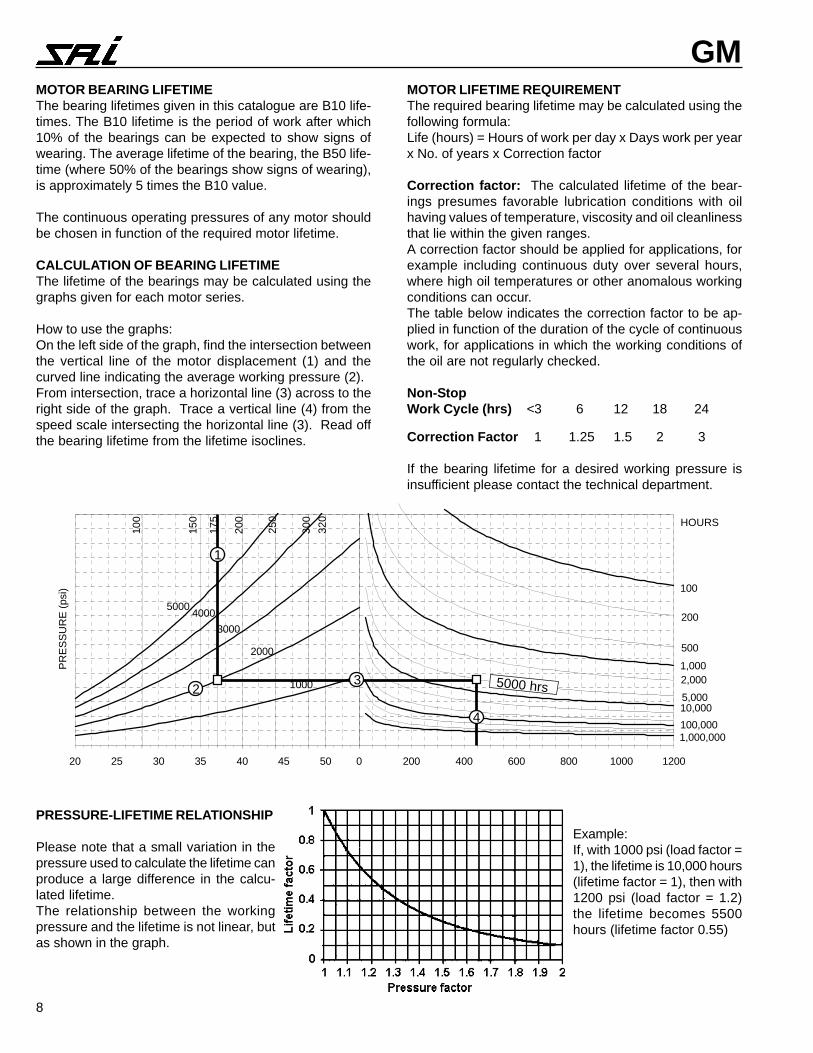
GMMOTOR BEARING LIFETIMEThe bearing lifetimes given in this catalogue are B10 life-times. The B10 lifetime is the period of work after which10% of the bearings can be expected to show signs ofwearing. The average lifetime of the bearing, the B50 life-time (where 50% of the bearings show signs of wearing),is approximately 5 times the B10 value.
The continuous operating pressures of any motor shouldbe chosen in function of the required motor lifetime.
CALCULATION OF BEARING LIFETIMEThe lifetime of the bearings may be calculated using thegraphs given for each motor series.
How to use the graphs:On the left side of the graph, find the intersection betweenthe vertical line of the motor displacement (1) and thecurved line indicating the average working pressure (2).From intersection, trace a horizontal line (3) across to theright side of the graph. Trace a vertical line (4) from thespeed scale intersecting the horizontal line (3). Read offthe bearing lifetime from the lifetime isoclines.
MOTOR LIFETIME REQUIREMENTThe required bearing lifetime may be calculated using thefollowing formula:Life (hours) = Hours of work per day x Days work per yearx No. of years x Correction factor
Correction factor: The calculated lifetime of the bear-ings presumes favorable lubrication conditions with oilhaving values of temperature, viscosity and oil cleanlinessthat lie within the given ranges.A correction factor should be applied for applications, forexample including continuous duty over several hours,where high oil temperatures or other anomalous workingconditions can occur.The table below indicates the correction factor to be ap-plied in function of the duration of the cycle of continuouswork, for applications in which the working conditions ofthe oil are not regularly checked.
Non-StopWork Cycle (hrs) <3 6 12 18 24
Correction Factor 1 1.25 1.5 2 3
If the bearing lifetime for a desired working pressure isinsufficient please contact the technical department.
0 200 400 600 800 1000 1200
100
1,000
10,000
100,0001,000,000
200
500
2,000
5,000
HOURS
20 25 30 35 40 45 50
PR
ES
SU
RE
(ps
i)
200
250
300
320
4000
2000
1000
3000
5000
175
150
100
1
2 5000 hrs3
4
PRESSURE-LIFETIME RELATIONSHIP
Please note that a small variation in thepressure used to calculate the lifetime canproduce a large difference in the calcu-lated lifetime.The relationship between the workingpressure and the lifetime is not linear, butas shown in the graph.
Example:If, with 1000 psi (load factor =1), the lifetime is 10,000 hours(lifetime factor = 1), then with1200 psi (load factor = 1.2)the lifetime becomes 5500hours (lifetime factor 0.55)
9
GM05
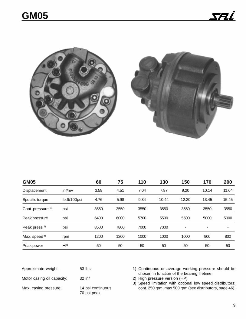
GM05 60 75 110 130 150 170 200
Displacement in3/rev 3.59 4.51 7.04 7.87 9.20 10.14 11.64
Specific torque lb.ft/100psi 4.76 5.98 9.34 10.44 12.20 13.45 15.45
Cont. pressure 1) psi 3550 3550 3550 3550 3550 3550 3550
Peak pressure psi 6400 6000 5700 5500 5500 5000 5000
Peak press 2) psi 8500 7800 7000 7000 - - -
Max. speed 3) rpm 1200 1200 1000 1000 1000 900 800
Peak power HP 50 50 50 50 50 50 50
1) Continuous or average working pressure should bechosen in function of the bearing lifetime.
2) High pressure version (HP).3) Speed limitation with optional low speed distributors:
cont. 250 rpm, max 500 rpm (see distributors, page 46).
Approximate weight: 53 lbs
Motor casing oil capacity: 32 in3
Max. casing pressure: 14 psi continuous70 psi peak
10
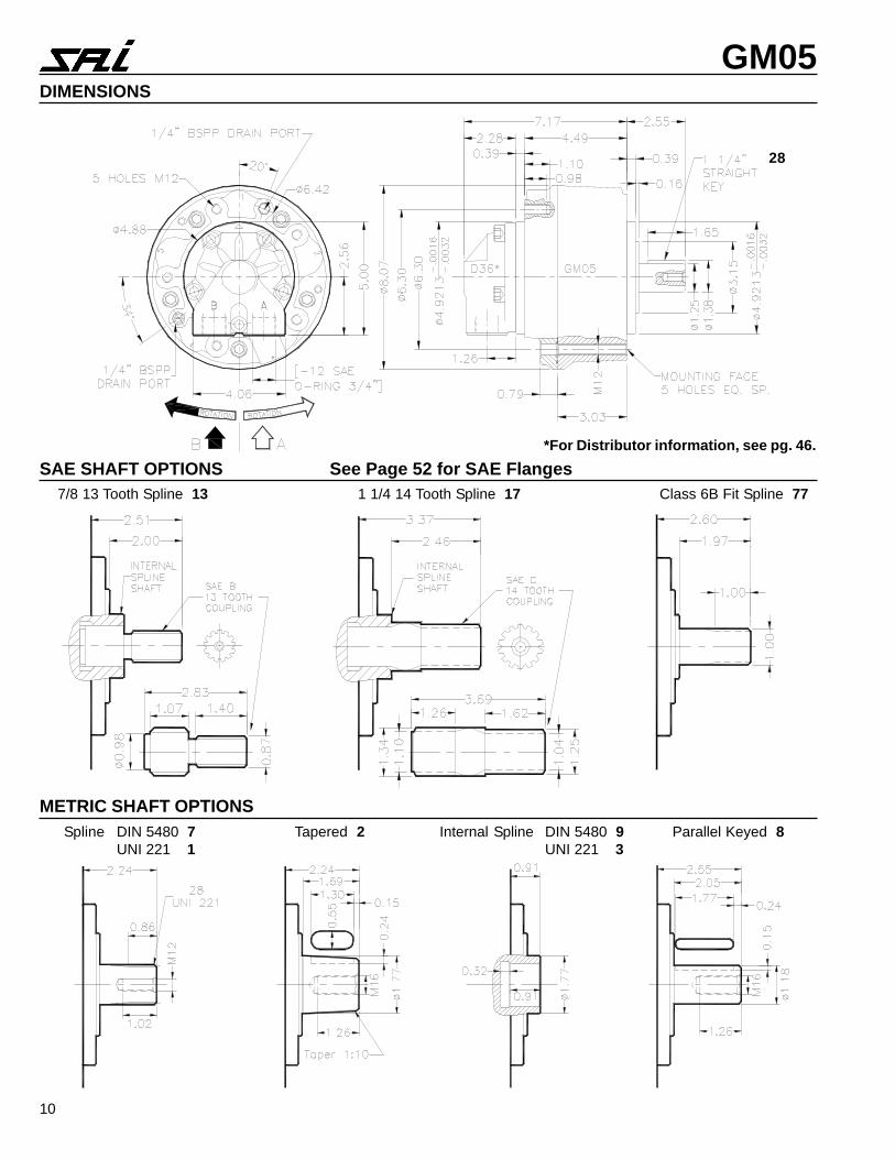
GM05DIMENSIONS
SAE SHAFT OPTIONS See Page 52 for SAE Flanges
28
7/8 13 Tooth Spline 13 1 1/4 14 Tooth Spline 17 Class 6B Fit Spline 77
METRIC SHAFT OPTIONSSpline DIN 5480 7
UNI 221 1Tapered 2 Internal Spline DIN 5480 9
UNI 221 3Parallel Keyed 8
*For Distributor information, see pg. 46.
11
GM05
MECHANICAL EFFICIENCY
0
1000
2000
3000
4000
5000
6000
7000
0 200 400 600 800 1000 1200
SPEED (rpm)
PR
ES
SU
RE
(ps
i)
92%
85%
89%
91%
VOLUMETRIC EFFICIENCY
0
5
10
15
20
25
30
0 200 400 600 800 1000 1200SPEED (rpm)
LEA
KA
GE
RA
TE
- (
cu.in
/min
)
5000 psi
1500 psi
3000 psi
4500 psi
IDLING AND BOOST PRESSURE
0
100
200
300
400
0 200 400 600 800 1000 1200
SPEED (rpm)
PR
ES
SU
RE
(ps
i) idling pressure
boost pressure
STARTING AND LOW SPEED TORQUE
0 5 10 15 20 25
SPEED (rpm)
TO
RQ
UE
92%
92%
90%
87%
6000 psi
4500 psi
3000 psi
1500 psi
SHAFT SPEED (rpm)
MOTOR DISPLACEMENT B10 LIFETIME
PISTON Ø (mm)
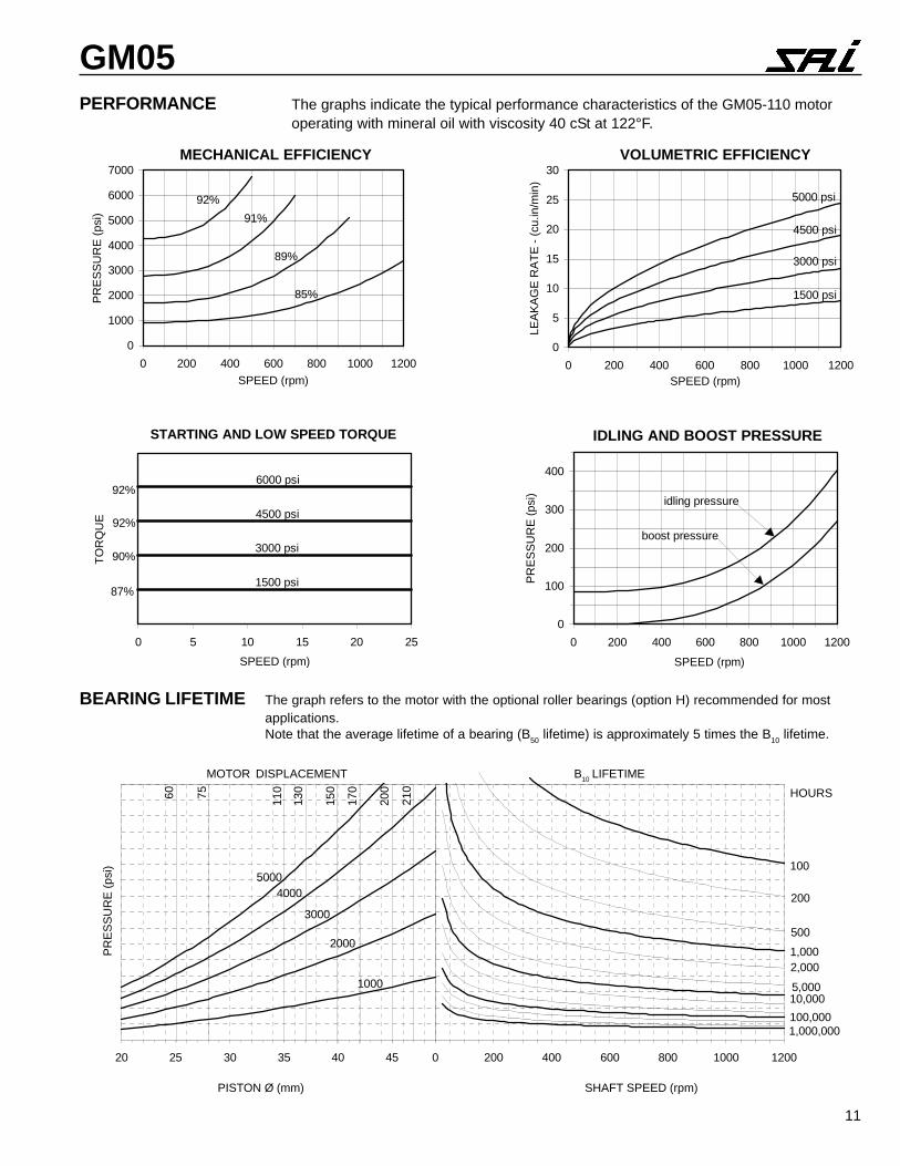
PERFORMANCE The graphs indicate the typical performance characteristics of the GM05-110 motoroperating with mineral oil with viscosity 40 cSt at 122°F.
BEARING LIFETIME The graph refers to the motor with the optional roller bearings (option H) recommended for mostapplications.Note that the average lifetime of a bearing (B50 lifetime) is approximately 5 times the B10 lifetime.
0 200 400 600 800 1000 1200
100
1,000
10,000
100,0001,000,000
200
500
2,000
5,000
HOURS
20 25 30 35 40 45
PR
ES
SU
RE
(ps
i)
150
170
200
110
4000
2000
1000
3000
5000
1307560 210
12
GM05
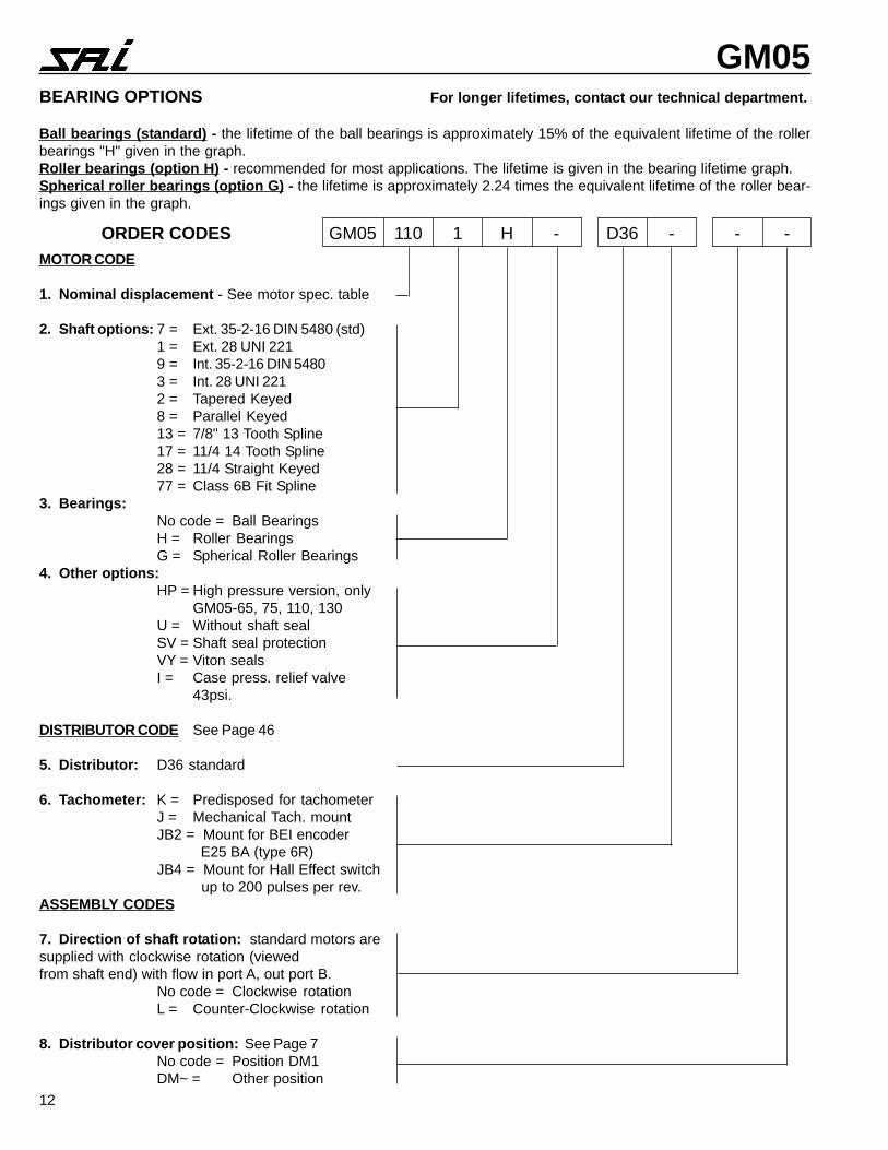
ORDER CODES GM05 110 1 H - D36 - - -MOTOR CODE
1. Nominal displacement - See motor spec. table
2. Shaft options: 7 = Ext. 35-2-16 DIN 5480 (std)1 = Ext. 28 UNI 2219 = Int. 35-2-16 DIN 54803 = Int. 28 UNI 2212 = Tapered Keyed8 = Parallel Keyed13 = 7/8" 13 Tooth Spline17 = 11/4 14 Tooth Spline28 = 11/4 Straight Keyed77 = Class 6B Fit Spline
3. Bearings:No code = Ball BearingsH = Roller BearingsG = Spherical Roller Bearings
4. Other options:HP = High pressure version, only
GM05-65, 75, 110, 130U = Without shaft sealSV = Shaft seal protectionVY = Viton sealsI = Case press. relief valve
43psi.
DISTRIBUTOR CODE See Page 46
5. Distributor: D36 standard
6. Tachometer: K = Predisposed for tachometerJ = Mechanical Tach. mountJB2 = Mount for BEI encoder
E25 BA (type 6R)JB4 = Mount for Hall Effect switch
up to 200 pulses per rev.ASSEMBLY CODES
7. Direction of shaft rotation: standard motors aresupplied with clockwise rotation (viewedfrom shaft end) with flow in port A, out port B.
No code = Clockwise rotationL = Counter-Clockwise rotation
8. Distributor cover position: See Page 7No code = Position DM1DM~ = Other position
BEARING OPTIONS For longer lifetimes, contact our technical department.
Ball bearings (standard) - the lifetime of the ball bearings is approximately 15% of the equivalent lifetime of the rollerbearings "H" given in the graph.Roller bearings (option H) - recommended for most applications. The lifetime is given in the bearing lifetime graph.Spherical roller bearings (option G) - the lifetime is approximately 2.24 times the equivalent lifetime of the roller bear-ings given in the graph.
13
GM1
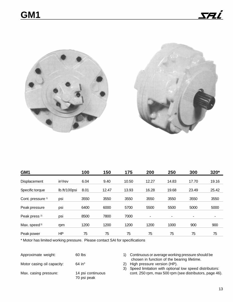
GM1 100 150 175 200 250 300 320*
Displacement in3/rev 6.04 9.40 10.50 12.27 14.83 17.70 19.16
Specific torque lb.ft/100psi 8.01 12.47 13.93 16.28 19.68 23.49 25.42
Cont. pressure 1) psi 3550 3550 3550 3550 3550 3550 3550
Peak pressure psi 6400 6000 5700 5500 5500 5000 5000
Peak press 2) psi 8500 7800 7000 - - - -
Max. speed 3) rpm 1200 1200 1200 1200 1000 900 900
Peak power HP 75 75 75 75 75 75 75
Approximate weight: 60 lbs
Motor casing oil capacity: 64 in3
Max. casing pressure: 14 psi continuous70 psi peak
1) Continuous or average working pressure should be chosen in function of the bearing lifetime.
2) High pressure version (HP).3) Speed limitation with optional low speed distributors:
cont. 250 rpm, max 500 rpm (see distributors, page 46).
* Motor has limited working pressure. Please contact SAI for specifications
14
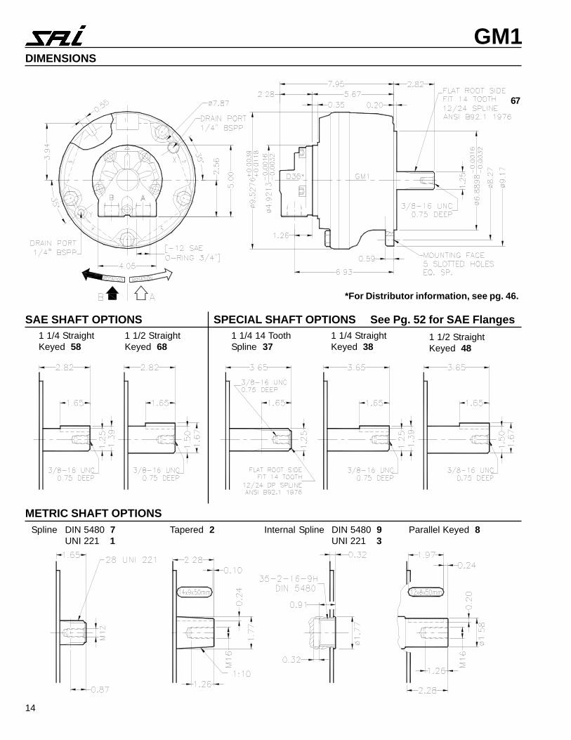
GM1DIMENSIONS
SAE SHAFT OPTIONS SPECIAL SHAFT OPTIONS See Pg. 52 for SAE Flanges
67
1 1/4 StraightKeyed 58
1 1/2 StraightKeyed 68
1 1/4 14 ToothSpline 37
METRIC SHAFT OPTIONSSpline DIN 5480 7
UNI 221 1Tapered 2 Internal Spline DIN 5480 9
UNI 221 3Parallel Keyed 8
1 1/4 StraightKeyed 38
1 1/2 StraightKeyed 48
*For Distributor information, see pg. 46.
15
GM1
0 200 400 600 800 1000 1200
100
1,000
10,000
100,0001,000,000
200
500
2,000
5,000
HOURS
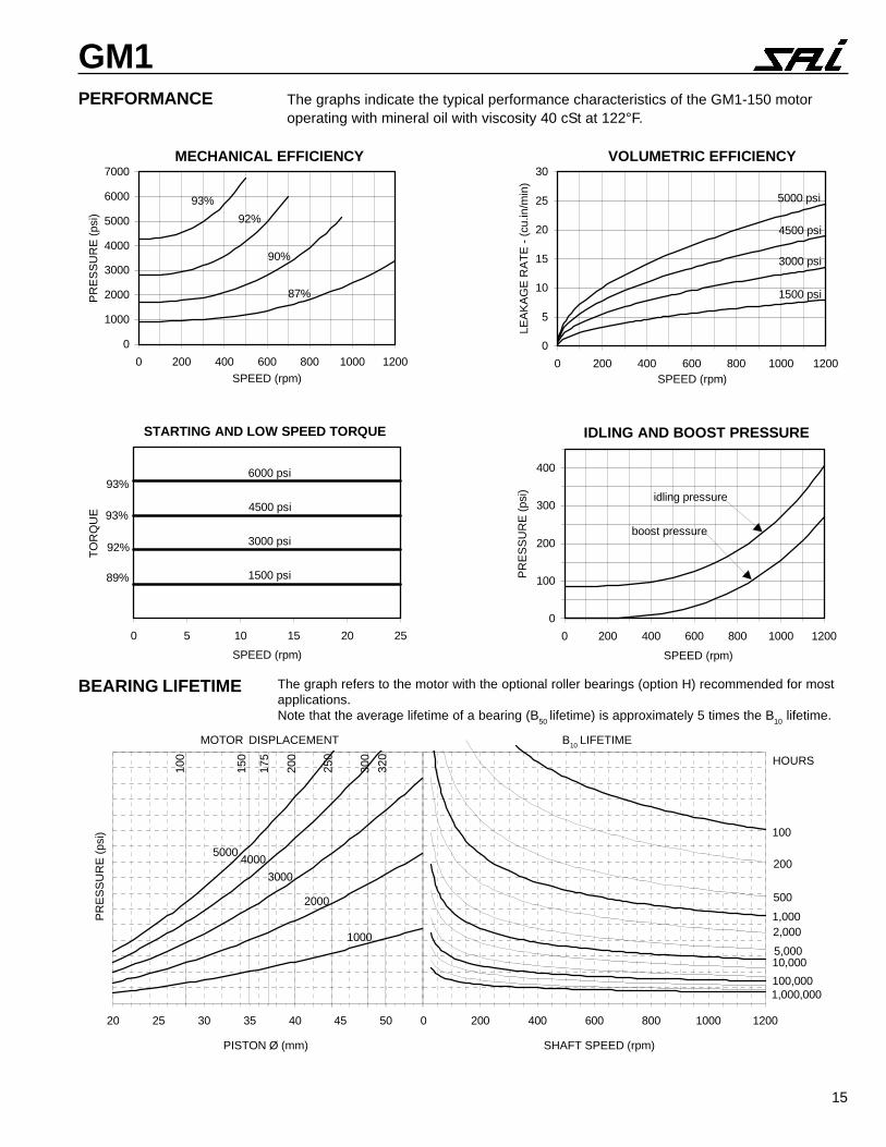
PERFORMANCE The graphs indicate the typical performance characteristics of the GM1-150 motoroperating with mineral oil with viscosity 40 cSt at 122°F.
VOLUMETRIC EFFICIENCY
0
5
10
15
20
25
30
0 200 400 600 800 1000 1200SPEED (rpm)
LEA
KA
GE
RA
TE
- (
cu.in
/min
)
5000 psi
1500 psi
3000 psi
4500 psi
IDLING AND BOOST PRESSURE
0
100
200
300
400
0 200 400 600 800 1000 1200
SPEED (rpm)
PR
ES
SU
RE
(ps
i) idling pressure
boost pressure
STARTING AND LOW SPEED TORQUE
0 5 10 15 20 25
SPEED (rpm)
TO
RQ
UE
93%
93%
92%
89%
6000 psi
4500 psi
3000 psi
1500 psi
MECHANICAL EFFICIENCY
0
1000
2000
3000
4000
5000
6000
7000
0 200 400 600 800 1000 1200
SPEED (rpm)
PR
ES
SU
RE
(ps
i)
93%
87%
90%
92%
SHAFT SPEED (rpm)PISTON Ø (mm)
The graph refers to the motor with the optional roller bearings (option H) recommended for mostapplications.Note that the average lifetime of a bearing (B50 lifetime) is approximately 5 times the B10 lifetime.
BEARING LIFETIME
MOTOR DISPLACEMENT B10 LIFETIME
20 25 30 35 40 45 50
PR
ES
SU
RE
(ps
i)
200
250
300
320
4000
2000
1000
3000
5000
175
150
100
16
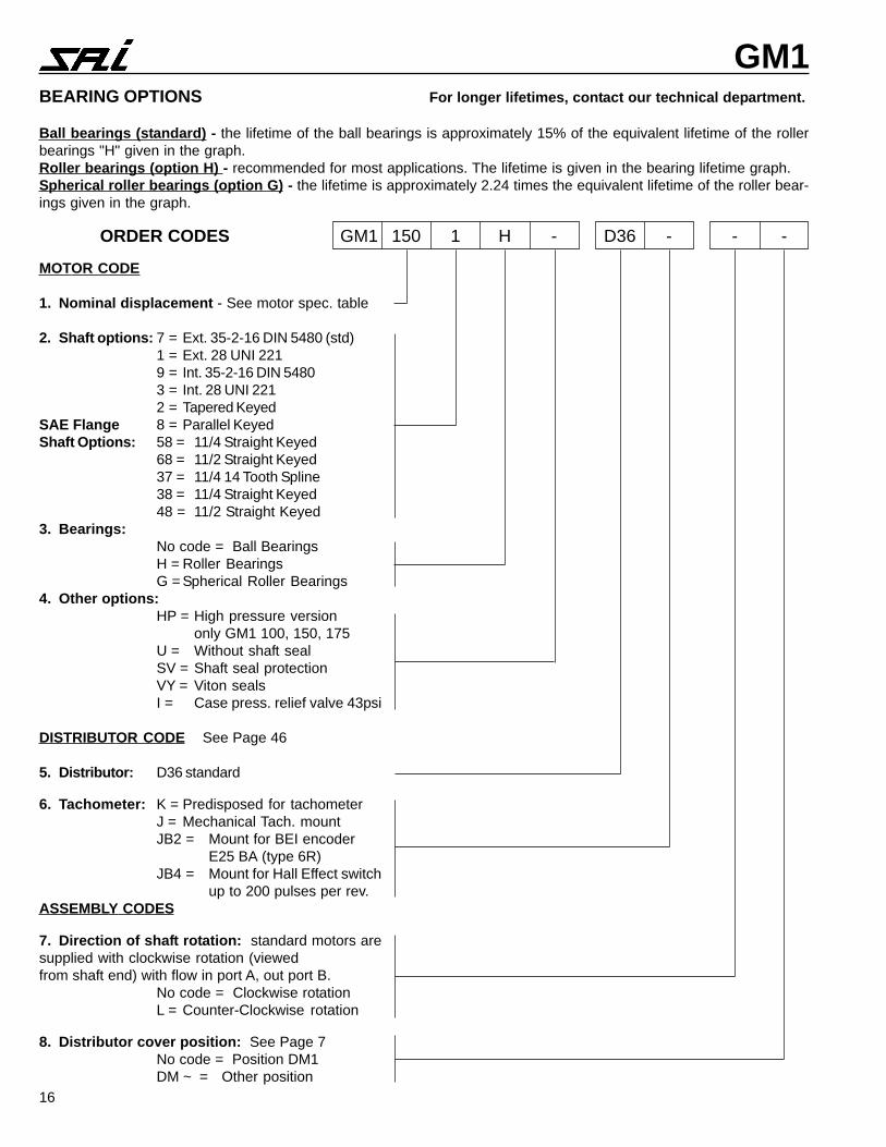
GM1BEARING OPTIONS For longer lifetimes, contact our technical department.
Ball bearings (standard) - the lifetime of the ball bearings is approximately 15% of the equivalent lifetime of the rollerbearings "H" given in the graph.Roller bearings (option H) - recommended for most applications. The lifetime is given in the bearing lifetime graph.Spherical roller bearings (option G) - the lifetime is approximately 2.24 times the equivalent lifetime of the roller bear-ings given in the graph.
ORDER CODES GM1 150 1 H - D36 - - -
MOTOR CODE
1. Nominal displacement - See motor spec. table
2. Shaft options: 7 = Ext. 35-2-16 DIN 5480 (std)1 = Ext. 28 UNI 2219 = Int. 35-2-16 DIN 54803 = Int. 28 UNI 2212 = Tapered Keyed
SAE Flange 8 = Parallel KeyedShaft Options: 58 = 11/4 Straight Keyed
68 = 11/2 Straight Keyed37 = 11/4 14 Tooth Spline38 = 11/4 Straight Keyed48 = 11/2 Straight Keyed
3. Bearings:No code = Ball BearingsH = Roller BearingsG = Spherical Roller Bearings
4. Other options:HP = High pressure version
only GM1 100, 150, 175U = Without shaft sealSV = Shaft seal protectionVY = Viton sealsI = Case press. relief valve 43psi
DISTRIBUTOR CODE See Page 46
5. Distributor: D36 standard
6. Tachometer: K = Predisposed for tachometerJ = Mechanical Tach. mountJB2 = Mount for BEI encoder
E25 BA (type 6R)JB4 = Mount for Hall Effect switch
up to 200 pulses per rev.ASSEMBLY CODES
7. Direction of shaft rotation: standard motors aresupplied with clockwise rotation (viewedfrom shaft end) with flow in port A, out port B.
No code = Clockwise rotationL = Counter-Clockwise rotation
8. Distributor cover position: See Page 7No code = Position DM1DM ~ = Other position
17
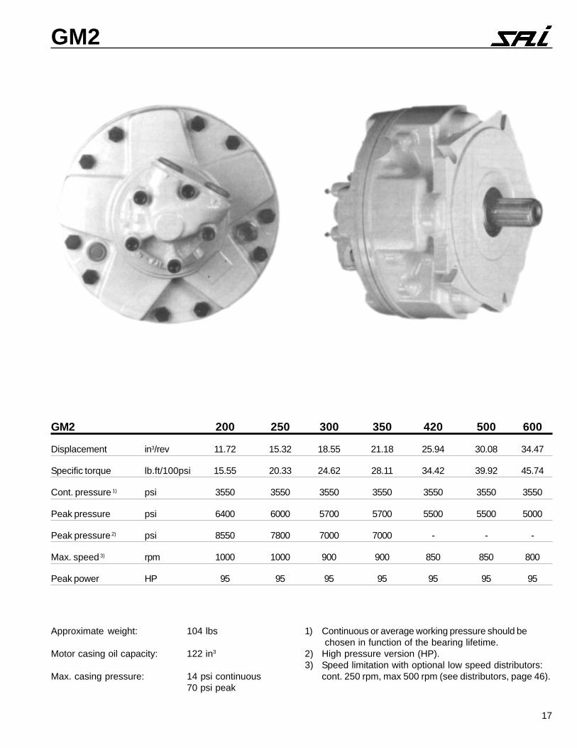
GM2
Approximate weight: 104 lbs
Motor casing oil capacity: 122 in3
Max. casing pressure: 14 psi continuous70 psi peak
1) Continuous or average working pressure should be chosen in function of the bearing lifetime.
2) High pressure version (HP).3) Speed limitation with optional low speed distributors:
cont. 250 rpm, max 500 rpm (see distributors, page 46).
GM2 200 250 300 350 420 500 600
Displacement in3/rev 11.72 15.32 18.55 21.18 25.94 30.08 34.47
Specific torque lb.ft/100psi 15.55 20.33 24.62 28.11 34.42 39.92 45.74
Cont. pressure 1) psi 3550 3550 3550 3550 3550 3550 3550
Peak pressure psi 6400 6000 5700 5700 5500 5500 5000
Peak pressure 2) psi 8550 7800 7000 7000 - - -
Max. speed 3) rpm 1000 1000 900 900 850 850 800
Peak power HP 95 95 95 95 95 95 95
18
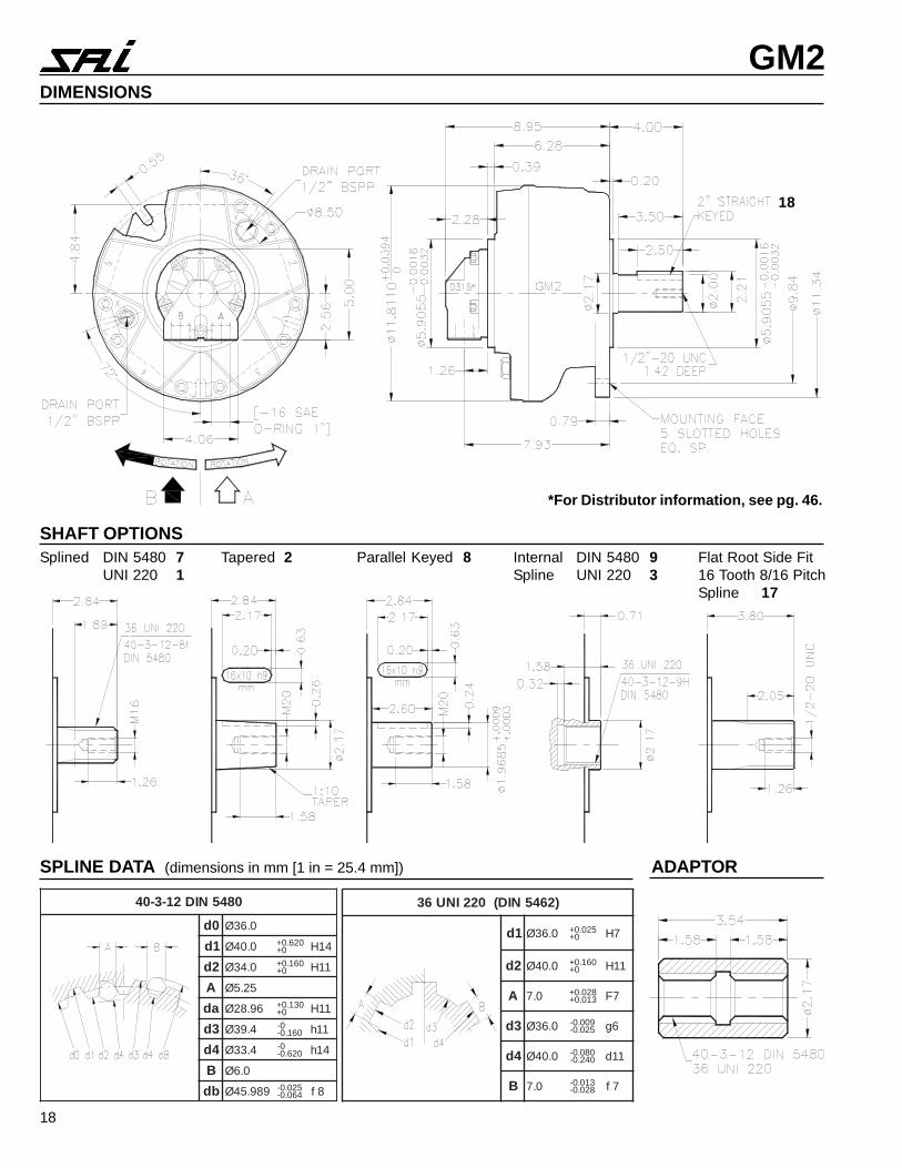
GM2DIMENSIONS
18
SHAFT OPTIONSSplined DIN 5480 7
UNI 220 1Tapered 2 Parallel Keyed 8 Internal DIN 5480 9
Spline UNI 220 3Flat Root Side Fit16 Tooth 8/16 PitchSpline 17
SPLINE DATA (dimensions in mm [1 in = 25.4 mm]) ADAPTOR
*For Distributor information, see pg. 46.
0845NID21-3-04
0d 0.63Ø
1d 0.04Ø 026.0+0+ 41H
2d 0.43Ø 061.0+0+ 11H
A 52.5Ø
ad 69.82Ø 031.0+0+ 11H
3d 4.93Ø 0-061.0- 11h
4d 4.33Ø 0-026.0- 41h
B 0.6Ø
bd 989.54Ø 520.0-460.0- 8f
)2645NID(022INU63
1d 0.63Ø 520.0+0+ 7H
2d 0.04Ø 061.0+0+ 11H
A 0.7 820.0+310.0+ 7F
3d 0.63Ø 900.0-520.0- 6g
4d 0.04Ø 080.0-042.0- 11d
B 0.7 310.0-820.0- 7f
19
GM2
MECHANICAL EFFICIENCY
0
1000
2000
3000
4000
5000
6000
0 200 400 600 800 1000
SPEED (rpm)
PR
ES
SU
RE
- (
psi) 93%
88%
91%
92%
VOLUMETRIC EFFICIENCY
0
5
10
15
20
25
30
0 200 400 600 800 1000
SPEED (rpm)
LEA
KA
GE
RA
TE
(cu
.ins/
min
) 6000 psi
1500 psi
3000 psi
4500 psi
STARTING AND LOW SPEED TORQUE
0 5 10 15 20 25
SPEED (rpm)
TO
RQ
UE
93%
93%
92%
89%
6000 psi
4500 psi
3000 psi
1500 psi
IDLING AND BOOST PRESSURE
0
100
200
300
400
0 200 400 600 800 1000
SPEED (rpm)
PR
ES
SU
RE
(ps
i)
idling pressure
boost pressure
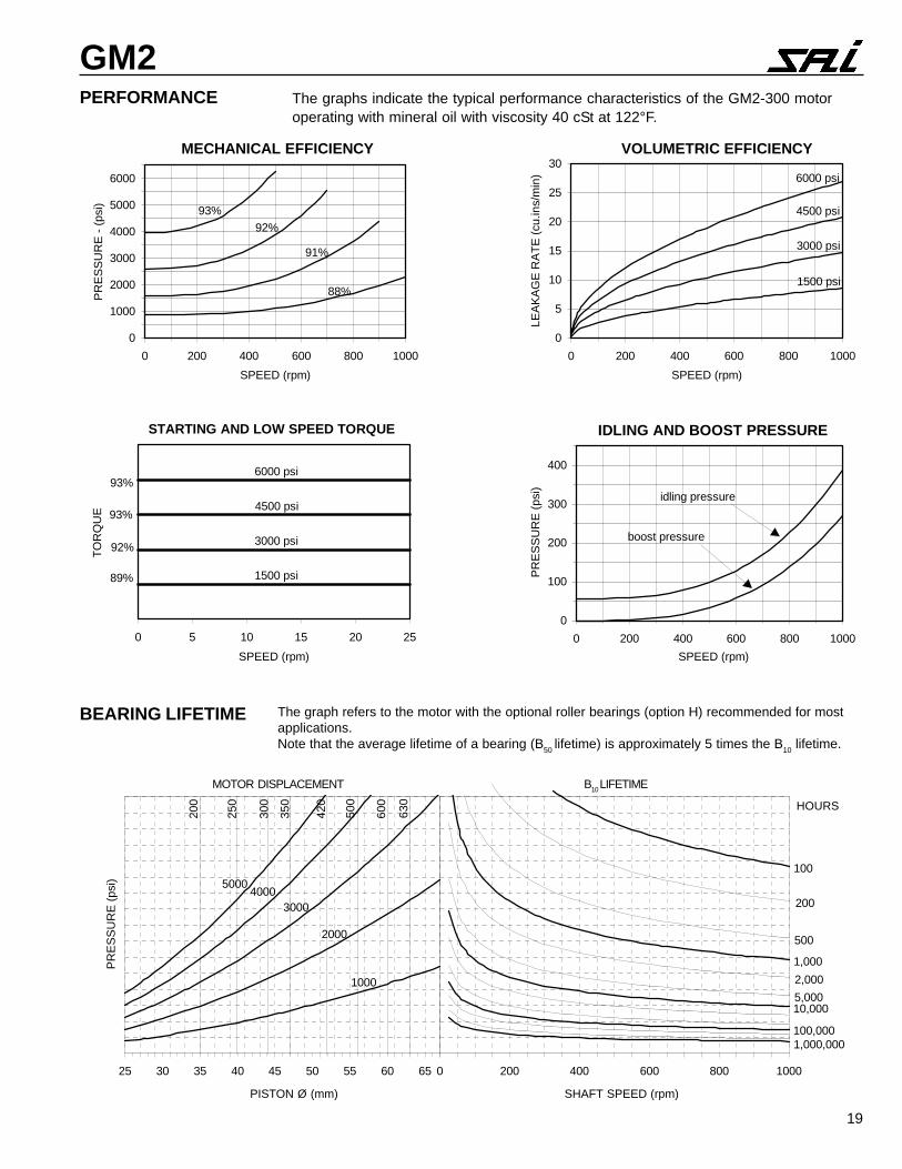
BEARING LIFETIME The graph refers to the motor with the optional roller bearings (option H) recommended for mostapplications.Note that the average lifetime of a bearing (B50 lifetime) is approximately 5 times the B10 lifetime.
25 30 35 40 45 50 55 60 65
PR
ES
SU
RE
(ps
i)
420
500
600
630
4000
2000
1000
3000
5000
350
300
250
200
0 200 400 600 800 1000
100
1,000
10,000
100,0001,000,000
200
500
2,000
5,000
HOURS
SHAFT SPEED (rpm)PISTON Ø (mm)
PERFORMANCE The graphs indicate the typical performance characteristics of the GM2-300 motoroperating with mineral oil with viscosity 40 cSt at 122°F.
MOTOR DISPLACEMENT B10 LIFETIME
20
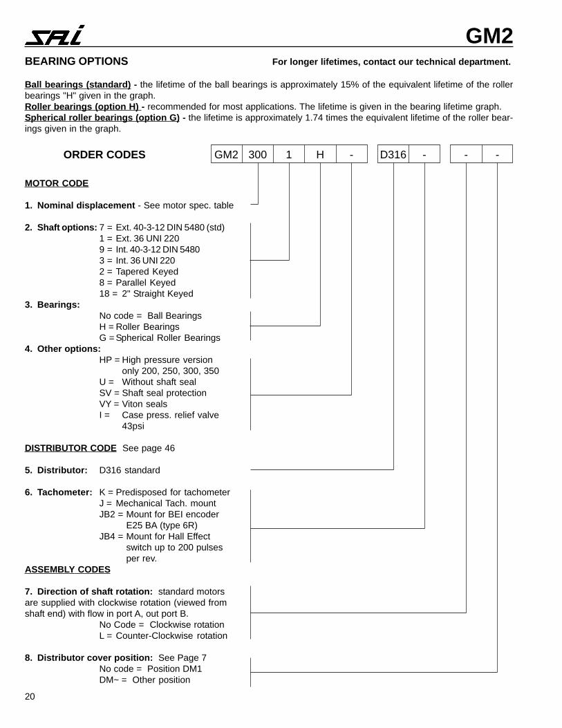
GM2BEARING OPTIONS For longer lifetimes, contact our technical department.
Ball bearings (standard) - the lifetime of the ball bearings is approximately 15% of the equivalent lifetime of the rollerbearings "H" given in the graph.Roller bearings (option H) - recommended for most applications. The lifetime is given in the bearing lifetime graph.Spherical roller bearings (option G) - the lifetime is approximately 1.74 times the equivalent lifetime of the roller bear-ings given in the graph.
MOTOR CODE
1. Nominal displacement - See motor spec. table
2. Shaft options: 7 = Ext. 40-3-12 DIN 5480 (std)1 = Ext. 36 UNI 2209 = Int. 40-3-12 DIN 54803 = Int. 36 UNI 2202 = Tapered Keyed8 = Parallel Keyed18 = 2" Straight Keyed
3. Bearings:No code = Ball BearingsH = Roller BearingsG = Spherical Roller Bearings
4. Other options:HP = High pressure version
only 200, 250, 300, 350U = Without shaft sealSV = Shaft seal protectionVY = Viton sealsI = Case press. relief valve
43psi
DISTRIBUTOR CODE See page 46
5. Distributor: D316 standard
6. Tachometer: K = Predisposed for tachometerJ = Mechanical Tach. mountJB2 = Mount for BEI encoder
E25 BA (type 6R)JB4 = Mount for Hall Effect
switch up to 200 pulsesper rev.
ASSEMBLY CODES
7. Direction of shaft rotation: standard motorsare supplied with clockwise rotation (viewed fromshaft end) with flow in port A, out port B.
No Code = Clockwise rotationL = Counter-Clockwise rotation
8. Distributor cover position: See Page 7No code = Position DM1DM~ = Other position
ORDER CODES GM2 300 1 H - D316 - - -
21
GM3/GM3A
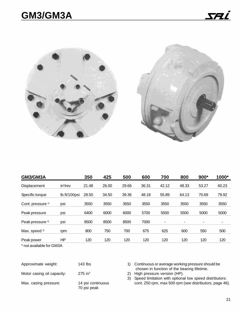
Approximate weight: 143 lbs
Motor casing oil capacity: 275 in3
Max. casing pressure: 14 psi continuous70 psi peak
1) Continuous or average working pressure should be chosen in function of the bearing lifetime.
2) High pressure version (HP).3) Speed limitation with optional low speed distributors:
cont. 250 rpm, max 500 rpm (see distributors, page 46).
GM3/GM3A 350 425 500 600 700 800 900* 1000*
Displacement in3/rev 21.48 26.00 29.66 36.31 42.12 48.33 53.27 60.23
Specific torque lb.ft/100psi 28.50 34.50 39.36 48.18 55.89 64.13 70.69 79.92
Cont. pressure 1) psi 3550 3550 3550 3550 3550 3550 3550 3550
Peak pressure psi 6400 6000 6000 5700 5500 5500 5000 5000
Peak pressure 2) psi 8500 8500 8500 7000 - - - -
Max. speed 3) rpm 800 750 700 675 625 600 550 500
Peak power HP 120 120 120 120 120 120 120 120
* not available for GM3A
22
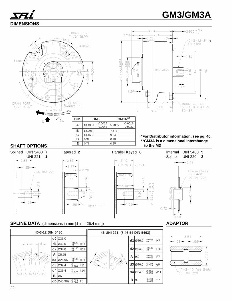
GM3/GM3ADIMENSIONS
7
SHAFT OPTIONSSplined DIN 5480 7
UNI 221 1Tapered 2 Parallel Keyed 8 Internal DIN 5480 9
Spline UNI 220 3
SPLINE DATA (dimensions in mm [1 in = 25.4 mm]) ADAPTOR
*For Distributor information, see pg. 46.**GM3A is a dimensional interchange to the M3
0845NID21-3-04
0d 0.63Ø
1d 0.04Ø 026.0+0+ 41H
2d 0.43Ø 061.0+0+ 11H
A 52.5Ø
ad 69.82Ø 031.0+0+ 11H
3d 4.93Ø 0-061.0- 11h
4d 4.33Ø 0-026.0- 41h
B 0.6Ø
bd 989.54Ø 520.0-460.0- 8f
)3645NID45-64-8(122INU64
1d 0.64Ø 520.0+0+ 7H
2d 0.45Ø 091.0+0+ 11H
A 0.9 820.0+310.0+ 7F
3d 0.64Ø 900.0-520.0- 6g
4d 0.45Ø 001.0-092.0- 11d
B 0.9 310.0-820.0- 7f
.MID 3MG A3MG
A 1334.015200.0-5400.0-
5509.56100.0-2300.0-
B 502.21 776.7
C 564.31 348.9
D 93.0 02.0
E 97.0 55.0
**
23
GM3/GM3A
0 200 400 600 800
100
1,000
10,000
100,0001,000,000
200
500
2,000
5,000
HOURS
35 40 45 50 55 60 65
PR
ES
SU
RE
(ps
i)
600
700
800
4000
2000
1000
3000
5000
425
350
1000500
900
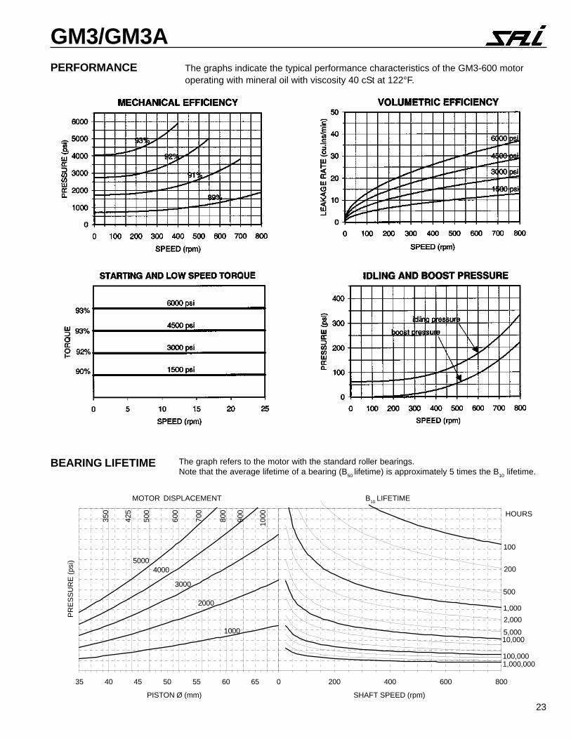
PERFORMANCE The graphs indicate the typical performance characteristics of the GM3-600 motoroperating with mineral oil with viscosity 40 cSt at 122°F.
The graph refers to the motor with the standard roller bearings.Note that the average lifetime of a bearing (B50 lifetime) is approximately 5 times the B10 lifetime.
BEARING LIFETIME
SHAFT SPEED (rpm)PISTON Ø (mm)
MOTOR DISPLACEMENT B10 LIFETIME
24
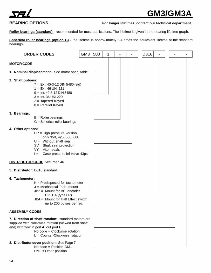
GM3/GM3ABEARING OPTIONS For longer lifetimes, contact our technical department.
Roller bearings (standard) - recommended for most applications. The lifetime is given in the bearing lifetime graph.
Spherical roller bearings (option G) - the lifetime is approximately 5.4 times the equivalent lifetime of the standardbearings.
MOTOR CODE
1. Nominal displacement - See motor spec. table
2. Shaft options:7 = Ext. 40-3-12 DIN 5480 (std)1 = Ext. 46 UNI 2219 = Int. 40-3-12 DIN 54803 = Int. 36 UNI 2202 = Tapered Keyed8 = Parallel Keyed
3. Bearings:E = Roller bearingsG = Spherical roller bearings
4. Other options:HP = High pressure version
only 350, 425, 500, 600U = Without shaft sealSV = Shaft seal protectionVY = Viton sealsI = Case press. relief valve 43psi
DISTRIBUTOR CODE See Page 46
5. Distributor: D316 standard
6. Tachometer:K = Predisposed for tachometerJ = Mechanical Tach. mountJB2 = Mount for BEI encoder
E25 BA (type 6R)JB4 = Mount for Hall Effect switch
up to 200 pulses per rev.
ASSEMBLY CODES
7. Direction of shaft rotation: standard motors aresupplied with clockwise rotation (viewed from shaftend) with flow in port A, out port B.
No code = Clockwise rotationL = Counter-Clockwise rotation
8. Distributor cover position: See Page 7No code = Position DM1DM~ = Other position
ORDER CODES GM3 500 1 - - D316 - - -
25
GM4
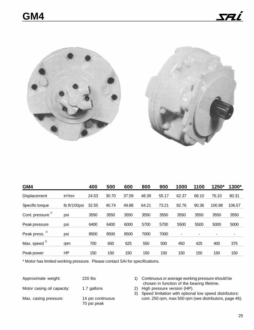
Approximate weight: 220 lbs
Motor casing oil capacity: 1.7 gallons
Max. casing pressure: 14 psi continuous70 psi peak
1) Continuous or average working pressure should be chosen in function of the bearing lifetime.
2) High pressure version (HP).3) Speed limitation with optional low speed distributors:
cont. 250 rpm, max 500 rpm (see distributors, page 46).
GM4 400 500 600 800 900 1000 1100 1250* 1300*
Displacement in3/rev 24.53 30.70 37.59 48.39 55.17 62.37 68.10 76.10 80.31
Specific torque lb.ft/100psi 32.55 40.74 49.88 64.21 73.21 82.76 90.36 100.98 106.57
Cont. pressure 1)
psi 3550 3550 3550 3550 3550 3550 3550 3550 3550
Peak pressure psi 6400 6400 6000 5700 5700 5500 5500 5000 5000
Peak press. 2)
psi 8500 8500 8500 7000 7000 - - - -
Max. speed 3)
rpm 700 650 625 550 500 450 425 400 375
Peak power HP 150 150 150 150 150 150 150 150 150
* Motor has limited working pressure. Please contact SAI for specifications.
26
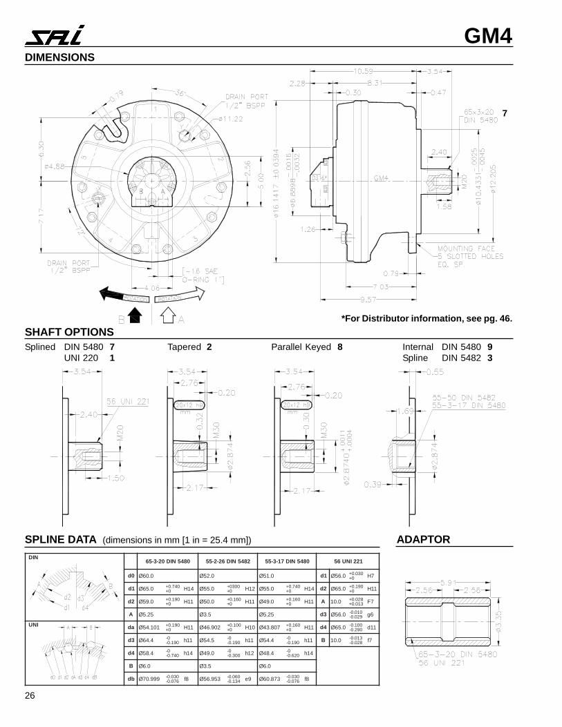
GM4DIMENSIONS
7
SHAFT OPTIONSSplined DIN 5480 7
UNI 220 1Tapered 2 Parallel Keyed 8 Internal DIN 5480 9
Spline DIN 5482 3
SPLINE DATA (dimensions in mm [1 in = 25.4 mm]) ADAPTOR
*For Distributor information, see pg. 46.
NID0845NID02-3-56 2845NID62-2-55 0845NID71-3-55 122INU65
0d 0.06Ø 0.25Ø 0.15Ø 1d 0.65Ø 030.0+0+ 7H
1d 0.56Ø 047.0+0+ 41H 0.55Ø 0030+
0+ 21H 0.55Ø 047.0+0+ 41H 2d 0.56Ø 091.0+
0+ 11H
2d 0.95Ø 091.0+0+ 11H 0.05Ø 061.0+
0+ 11H 0.94Ø 061.0+0+ 11H A 0.01 820.0+
310.0+ 7F
A 52.5Ø 5.3Ø 52.5Ø 3d 0.65Ø 010.0-920.0- 6g
INU ad 101.45Ø 091.0+0+ 11H 209.64Ø 001.0+
0+ 01H 708.34Ø 061.0+0+ 11H 4d 0.56Ø 001.0-
092.0- 11d
3d 4.46Ø 0-091.0- 11h 5.45Ø 0-
091.0- 11h 4.45Ø 0-091.0- 11h B 0.01 310.0-
820.0- 7f
4d 4.85Ø 0-047.0- 41h 0.94Ø 0-
003.0- 21h 4.84Ø 0-026.0- 41h
B 0.6Ø 5.3Ø 0.6Ø
bd 999.07Ø 030.0-670.0- 8f 359.65Ø 060.0-
431.0- 9e 378.06Ø 030.0-670.0- 8f
27
GM4
0 100 200 300 400 500 600 700
100
1,000
10,000
100,0001,000,000
200
500
2,000
5,000
HOURS
35 40 45 50 55 60 65 70 75
PR
ES
SU
RE
(ps
i)
4000
2000
1000
3000
5000
400
500
600
800
1100
1250
1300
900
1000
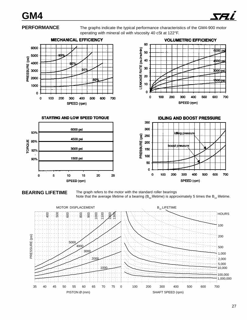
PERFORMANCE The graphs indicate the typical performance characteristics of the GM4-900 motoroperating with mineral oil with viscosity 40 cSt at 122°F.
SHAFT SPEED (rpm)PISTON Ø (mm)
MOTOR DISPLACEMENT B10 LIFETIME
BEARING LIFETIME The graph refers to the motor with the standard roller bearingsNote that the average lifetime of a bearing (B50 lifetime) is approximately 5 times the B10 lifetime.
28
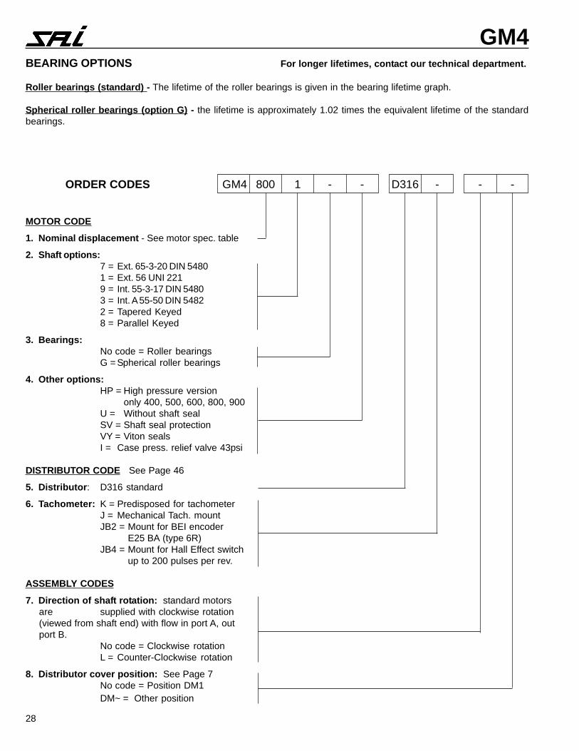
GM4BEARING OPTIONS For longer lifetimes, contact our technical department.
Roller bearings (standard) - The lifetime of the roller bearings is given in the bearing lifetime graph.
Spherical roller bearings (option G) - the lifetime is approximately 1.02 times the equivalent lifetime of the standardbearings.
MOTOR CODE
1. Nominal displacement - See motor spec. table
2. Shaft options:7 = Ext. 65-3-20 DIN 54801 = Ext. 56 UNI 2219 = Int. 55-3-17 DIN 54803 = Int. A 55-50 DIN 54822 = Tapered Keyed8 = Parallel Keyed
3. Bearings:No code = Roller bearingsG = Spherical roller bearings
4. Other options:HP = High pressure version
only 400, 500, 600, 800, 900U = Without shaft sealSV = Shaft seal protectionVY = Viton sealsI = Case press. relief valve 43psi
DISTRIBUTOR CODE See Page 46
5. Distributor: D316 standard
6. Tachometer: K = Predisposed for tachometerJ = Mechanical Tach. mountJB2 = Mount for BEI encoder
E25 BA (type 6R)JB4 = Mount for Hall Effect switch
up to 200 pulses per rev.
ASSEMBLY CODES
7. Direction of shaft rotation: standard motorsare supplied with clockwise rotation(viewed from shaft end) with flow in port A, outport B.
No code = Clockwise rotationL = Counter-Clockwise rotation
8. Distributor cover position: See Page 7No code = Position DM1DM~ = Other position
ORDER CODES GM4 800 1 - - D316 - - -
29
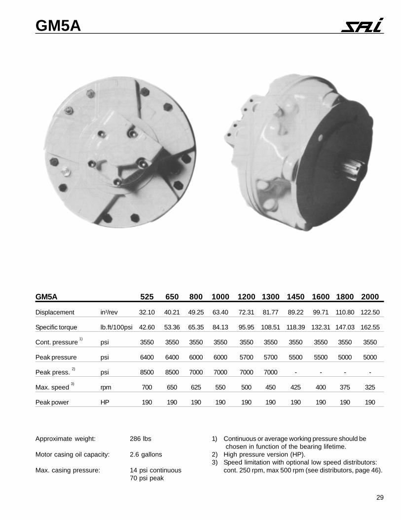
GM5A
Approximate weight: 286 lbs
Motor casing oil capacity: 2.6 gallons
Max. casing pressure: 14 psi continuous70 psi peak
1) Continuous or average working pressure should be chosen in function of the bearing lifetime.
2) High pressure version (HP).3) Speed limitation with optional low speed distributors:
cont. 250 rpm, max 500 rpm (see distributors, page 46).
GM5A 525 650 800 1000 1200 1300 1450 1600 1800 2000
Displacement in3/rev 32.10 40.21 49.25 63.40 72.31 81.77 89.22 99.71 110.80 122.50
Specific torque lb.ft/100psi 42.60 53.36 65.35 84.13 95.95 108.51 118.39 132.31 147.03 162.55
Cont. pressure 1)
psi 3550 3550 3550 3550 3550 3550 3550 3550 3550 3550
Peak pressure psi 6400 6400 6000 6000 5700 5700 5500 5500 5000 5000
Peak press. 2)
psi 8500 8500 7000 7000 7000 7000 - - - -
Max. speed 3)
rpm 700 650 625 550 500 450 425 400 375 325
Peak power HP 190 190 190 190 190 190 190 190 190 190
31
GM5A
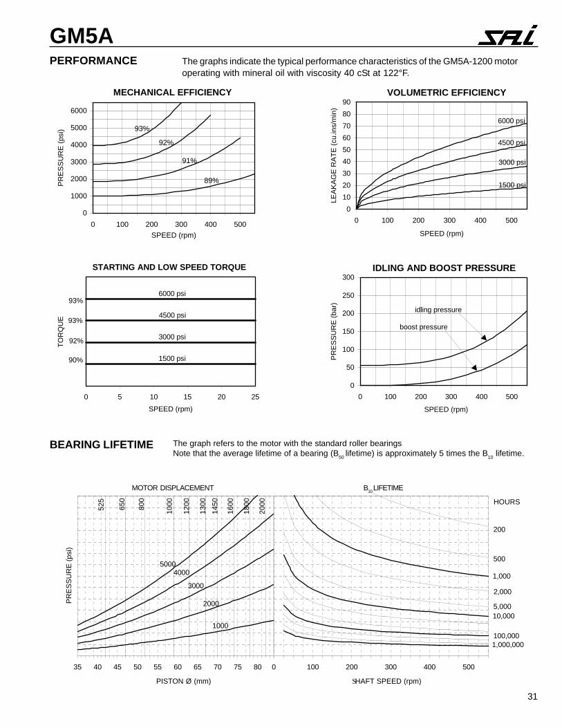
BEARING LIFETIME The graph refers to the motor with the standard roller bearingsNote that the average lifetime of a bearing (B50 lifetime) is approximately 5 times the B10 lifetime.
PERFORMANCE The graphs indicate the typical performance characteristics of the GM5A-1200 motoroperating with mineral oil with viscosity 40 cSt at 122°F.
MECHANICAL EFFICIENCY
0
1000
2000
3000
4000
5000
6000
0 100 200 300 400 500
SPEED (rpm)
PR
ES
SU
RE
(ps
i) 93%
89%
91%
92%
VOLUMETRIC EFFICIENCY
0
10
20
30
40
50
60
70
80
90
0 100 200 300 400 500
SPEED (rpm)
LEA
KA
GE
RA
TE
(cu
.ins/
min
)
6000 psi
1500 psi
3000 psi
4500 psi
STARTING AND LOW SPEED TORQUE
0 5 10 15 20 25
SPEED (rpm)
TO
RQ
UE
93%
93%
92%
90%
6000 psi
4500 psi
3000 psi
1500 psi
IDLING AND BOOST PRESSURE
0
50
100
150
200
250
300
0 100 200 300 400 500
SPEED (rpm)
PR
ES
SU
RE
(ba
r)
idling pressure
boost pressure
SHAFT SPEED (rpm)PISTON Ø (mm)
35 40 45 50 55 60 65 70 75 80
PR
ES
SU
RE
(ps
i)
4000
2000
1000
3000
5000
525
650
800
1000
1200
1300
1450
1600
1800
2000
0 100 200 300 400 500
1,000
10,000
100,0001,000,000
200
500
2,000
5,000
HOURS
MOTOR DISPLACEMENT B10 LIFETIME
32
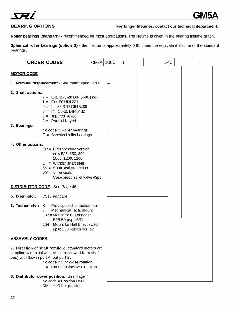
GM5ABEARING OPTIONS For longer lifetimes, contact our technical department.
Roller bearings (standard) - recommended for most applications. The lifetime is given in the bearing lifetime graph.
Spherical roller bearings (option G) - the lifetime is approximately 0.91 times the equivalent lifetime of the standardbearings.
MOTOR CODE
1. Nominal displacement - See motor spec. table
2. Shaft options:7 = Ext. 65-3-20 DIN 5480 (std)1 = Ext. 56 UNI 2219 = Int. 55-3-17 DIN 54803 = Int. 55-50 DIN 54822 = Tapered Keyed8 = Parallel Keyed
3. Bearings:No code = Roller bearingsG = Spherical roller bearings
4. Other options:HP = High pressure version
only 525, 650, 800,1000, 1200, 1300
U = Without shaft sealSV = Shaft seal protectionVY = Viton sealsI = Case press. relief valve 43psi
DISTRIBUTOR CODE See Page 46
5. Distributor: D316 standard
6. Tachometer: K = Predisposed for tachometerJ = Mechanical Tach. mountJB2 = Mount for BEI encoder
E25 BA (type 6R)JB4 = Mount for Hall Effect switch
up to 200 pulses per rev.
ASSEMBLY CODES
7. Direction of shaft rotation: standard motors aresupplied with clockwise rotation (viewed from shaftend) with flow in port A, out port B.
No code = Clockwise rotationL = Counter-Clockwise rotation
8. Distributor cover position: See Page 7No code = Position DM1DM~ = Other position
ORDER CODES GM5A 1000 1 - - D40 - - -
33
GM6
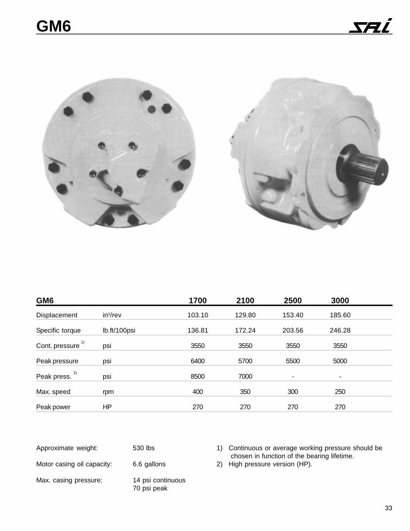
Approximate weight: 530 lbs
Motor casing oil capacity: 6.6 gallons
Max. casing pressure: 14 psi continuous70 psi peak
1) Continuous or average working pressure should be chosen in function of the bearing lifetime.
2) High pressure version (HP).
GM6 1700 2100 2500 3000
Displacement in3/rev 103.10 129.80 153.40 185.60
Specific torque lb.ft/100psi 136.81 172.24 203.56 246.28
Cont. pressure 1)
psi 3550 3550 3550 3550
Peak pressure psi 6400 5700 5500 5000
Peak press. 2)
psi 8500 7000 - -
Max. speed rpm 400 350 300 250
Peak power HP 270 270 270 270
34
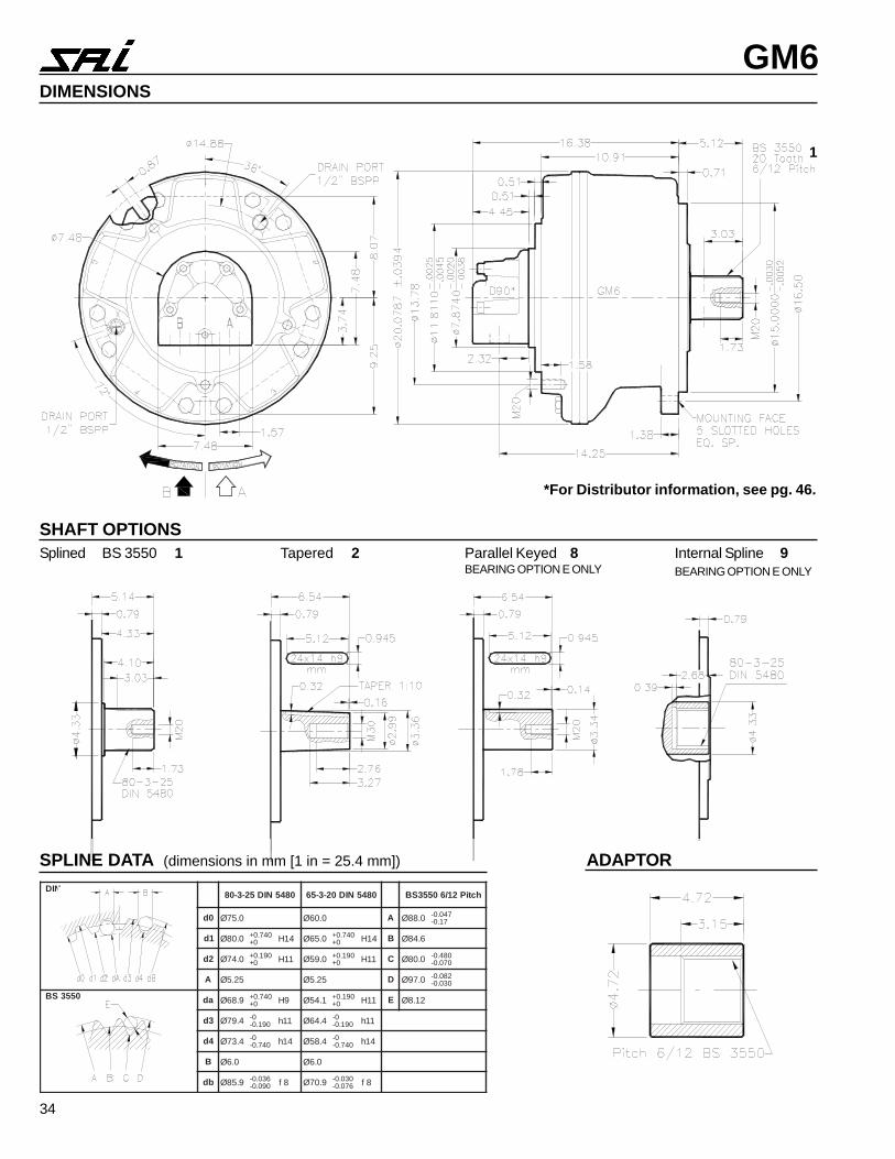
GM6DIMENSIONS
1
SPLINE DATA (dimensions in mm [1 in = 25.4 mm]) ADAPTOR
*For Distributor information, see pg. 46.
NID0845NID52-3-08 0845NID02-3-56 hctiP21/60553SB
0d 0.57Ø 0.06Ø A 0.88Ø 740.0-71.0-
1d 0.08Ø 047.0+0+ 41H 0.56Ø 047.0+
0+ 41H B 6.48Ø
2d 0.47Ø 091.0+0+ 11H 0.95Ø 091.0+
0+ 11H C 0.08Ø 084.0-070.0-
A 52.5Ø 52.5Ø D 0.79Ø 280.0-030.0-
0553SB ad 9.86Ø 047.0+0+ 9H 1.45Ø 091.0+
0+ 11H E 21.8Ø
3d 4.97Ø 0-091.0- 11h 4.46Ø 0-
091.0- 11h
4d 4.37Ø 0-047.0- 41h 4.85Ø 0-
047.0- 41h
B 0.6Ø 0.6Ø
bd 9.58Ø 630.0-090.0- 8f 9.07Ø 030.0-
670.0- 8f
SHAFT OPTIONSSplined BS 3550 1 Tapered 2 Parallel Keyed 8
BEARING OPTION E ONLYInternal Spline 9BEARING OPTION E ONLY
35
GM6
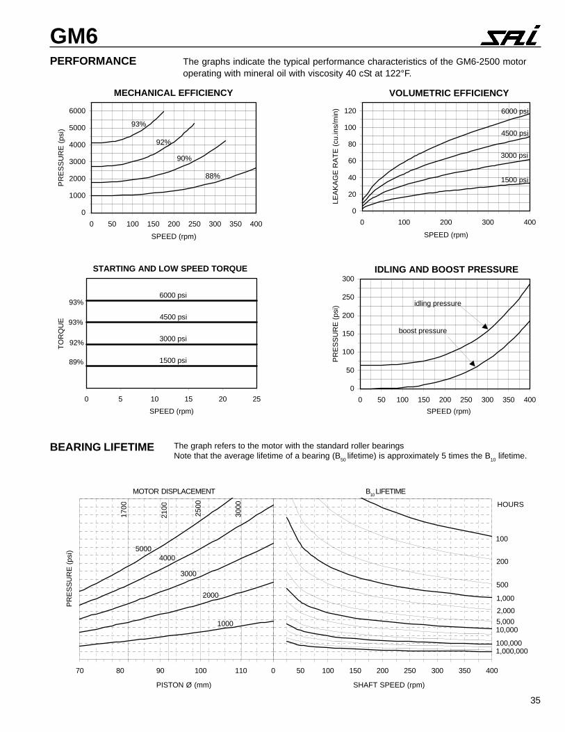
BEARING LIFETIME The graph refers to the motor with the standard roller bearingsNote that the average lifetime of a bearing (B50 lifetime) is approximately 5 times the B10 lifetime.
PERFORMANCE The graphs indicate the typical performance characteristics of the GM6-2500 motoroperating with mineral oil with viscosity 40 cSt at 122°F.
MECHANICAL EFFICIENCY
0
1000
2000
3000
4000
5000
6000
0 50 100 150 200 250 300 350 400
SPEED (rpm)
PR
ES
SU
RE
(ps
i)
93%
88%
90%
92%
VOLUMETRIC EFFICIENCY
0
20
40
60
80
100
120
0 100 200 300 400
SPEED (rpm)
LEA
KA
GE
RA
TE
(cu
.ins/
min
) 6000 psi
1500 psi
3000 psi
4500 psi
STARTING AND LOW SPEED TORQUE
0 5 10 15 20 25
SPEED (rpm)
TO
RQ
UE
93%
93%
92%
89%
6000 psi
4500 psi
3000 psi
1500 psi
IDLING AND BOOST PRESSURE
0
50
100
150
200
250
300
0 50 100 150 200 250 300 350 400
SPEED (rpm)
PR
ES
SU
RE
(ps
i) idling pressure
boost pressure
SHAFT SPEED (rpm)PISTON Ø (mm)
70 80 90 100 110
PR
ES
SU
RE
(ps
i)
3000
4000
2000
1000
3000
5000
2500
2100
1700
0 50 100 150 200 250 300 350 400
100
1,000
10,000
100,0001,000,000
200
500
2,000
5,000
HOURS
MOTOR DISPLACEMENT B10 LIFETIME
36
GM6BEARING OPTIONS
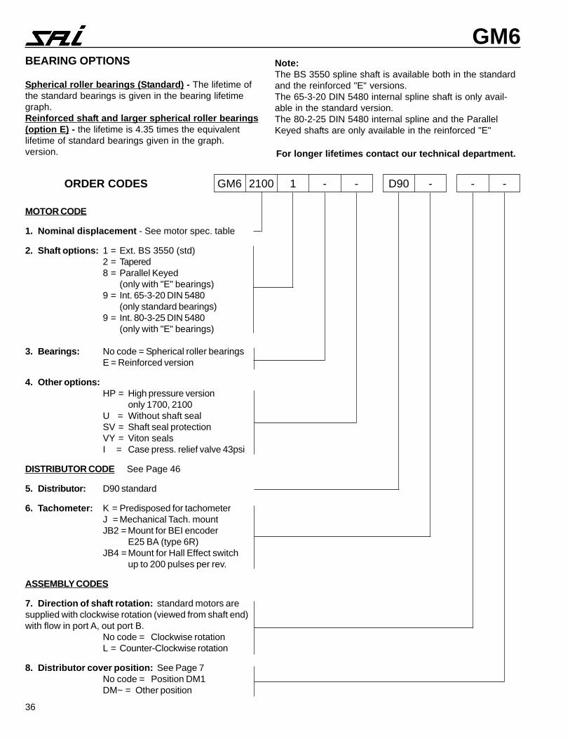
Spherical roller bearings (Standard) - The lifetime ofthe standard bearings is given in the bearing lifetimegraph.Reinforced shaft and larger spherical roller bearings(option E) - the lifetime is 4.35 times the equivalentlifetime of standard bearings given in the graph.version. For longer lifetimes contact our technical department.
Note:The BS 3550 spline shaft is available both in the standardand the reinforced "E" versions.The 65-3-20 DIN 5480 internal spline shaft is only avail-able in the standard version.The 80-2-25 DIN 5480 internal spline and the ParallelKeyed shafts are only available in the reinforced "E"
MOTOR CODE
1. Nominal displacement - See motor spec. table
2. Shaft options: 1 = Ext. BS 3550 (std)2 = Tapered8 = Parallel Keyed
(only with "E" bearings)9 = Int. 65-3-20 DIN 5480
(only standard bearings)9 = Int. 80-3-25 DIN 5480
(only with "E" bearings)
3. Bearings: No code = Spherical roller bearingsE = Reinforced version
4. Other options:HP = High pressure version
only 1700, 2100U = Without shaft sealSV = Shaft seal protectionVY = Viton sealsI = Case press. relief valve 43psi
DISTRIBUTOR CODE See Page 46
5. Distributor: D90 standard
6. Tachometer: K = Predisposed for tachometerJ = Mechanical Tach. mountJB2 = Mount for BEI encoder
E25 BA (type 6R)JB4 = Mount for Hall Effect switch
up to 200 pulses per rev.
ASSEMBLY CODES
7. Direction of shaft rotation: standard motors aresupplied with clockwise rotation (viewed from shaft end)with flow in port A, out port B.
No code = Clockwise rotationL = Counter-Clockwise rotation
8. Distributor cover position: See Page 7No code = Position DM1DM~ = Other position
ORDER CODES GM6 2100 1 - - D90 - - -
30
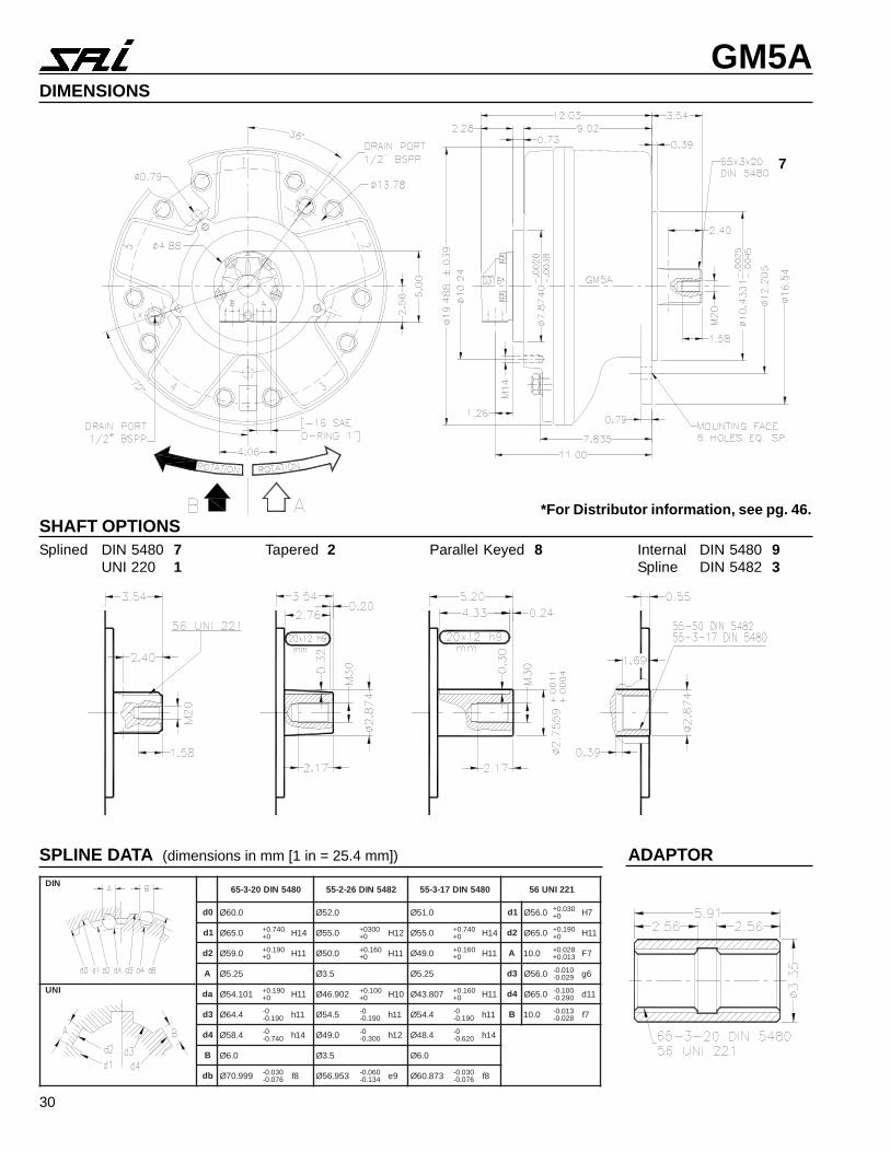
GM5ADIMENSIONS
7
SHAFT OPTIONSSplined DIN 5480 7
UNI 220 1Tapered 2 Parallel Keyed 8 Internal DIN 5480 9
Spline DIN 5482 3
SPLINE DATA (dimensions in mm [1 in = 25.4 mm]) ADAPTOR
*For Distributor information, see pg. 46.
NID0845NID02-3-56 2845NID62-2-55 0845NID71-3-55 122INU65
0d 0.06Ø 0.25Ø 0.15Ø 1d 0.65Ø 030.0+0+ 7H
1d 0.56Ø 047.0+0+ 41H 0.55Ø 0030+
0+ 21H 0.55Ø 047.0+0+ 41H 2d 0.56Ø 091.0+
0+ 11H
2d 0.95Ø 091.0+0+ 11H 0.05Ø 061.0+
0+ 11H 0.94Ø 061.0+0+ 11H A 0.01 820.0+
310.0+ 7F
A 52.5Ø 5.3Ø 52.5Ø 3d 0.65Ø 010.0-920.0- 6g
INU ad 101.45Ø 091.0+0+ 11H 209.64Ø 001.0+
0+ 01H 708.34Ø 061.0+0+ 11H 4d 0.56Ø 001.0-
092.0- 11d
3d 4.46Ø 0-091.0- 11h 5.45Ø 0-
091.0- 11h 4.45Ø 0-091.0- 11h B 0.01 310.0-
820.0- 7f
4d 4.85Ø 0-047.0- 41h 0.94Ø 0-
003.0- 21h 4.84Ø 0-026.0- 41h
B 0.6Ø 5.3Ø 0.6Ø
bd 999.07Ø 030.0-670.0- 8f 359.65Ø 060.0-
431.0- 9e 378.06Ø 030.0-670.0- 8f
37
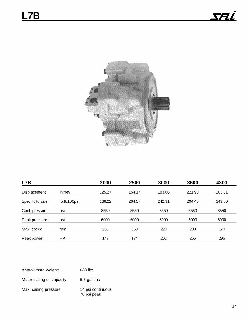
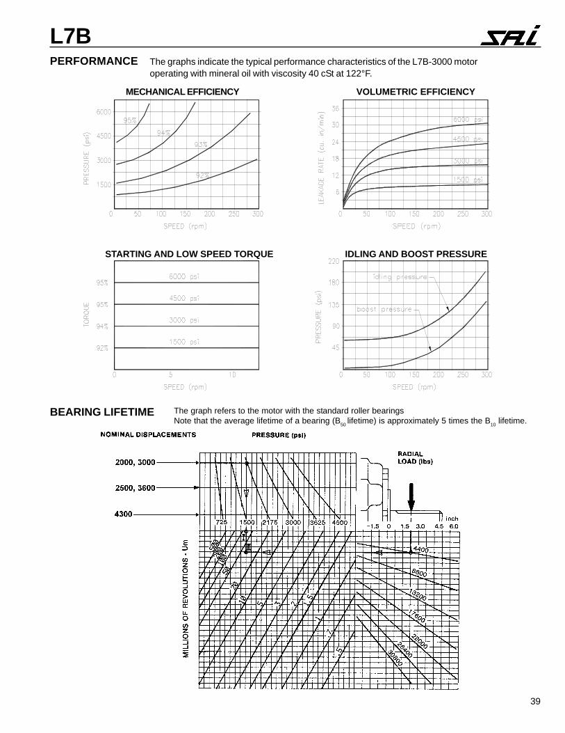
L7B
Approximate weight: 638 lbs
Motor casing oil capacity: 5.6 gallons
Max. casing pressure: 14 psi continuous70 psi peak
L7B 2000 2500 3000 3600 4300
Displacement in3/rev 125.27 154.17 183.06 221.90 263.61
Specific torque lb.ft/100psi 166.22 204.57 242.91 294.45 349.80
Cont. pressure psi 3550 3550 3550 3550 3550
Peak pressure psi 6000 6000 6000 6000 6000
Max. speed rpm 280 260 220 200 170
Peak power HP 147 174 202 255 295
38
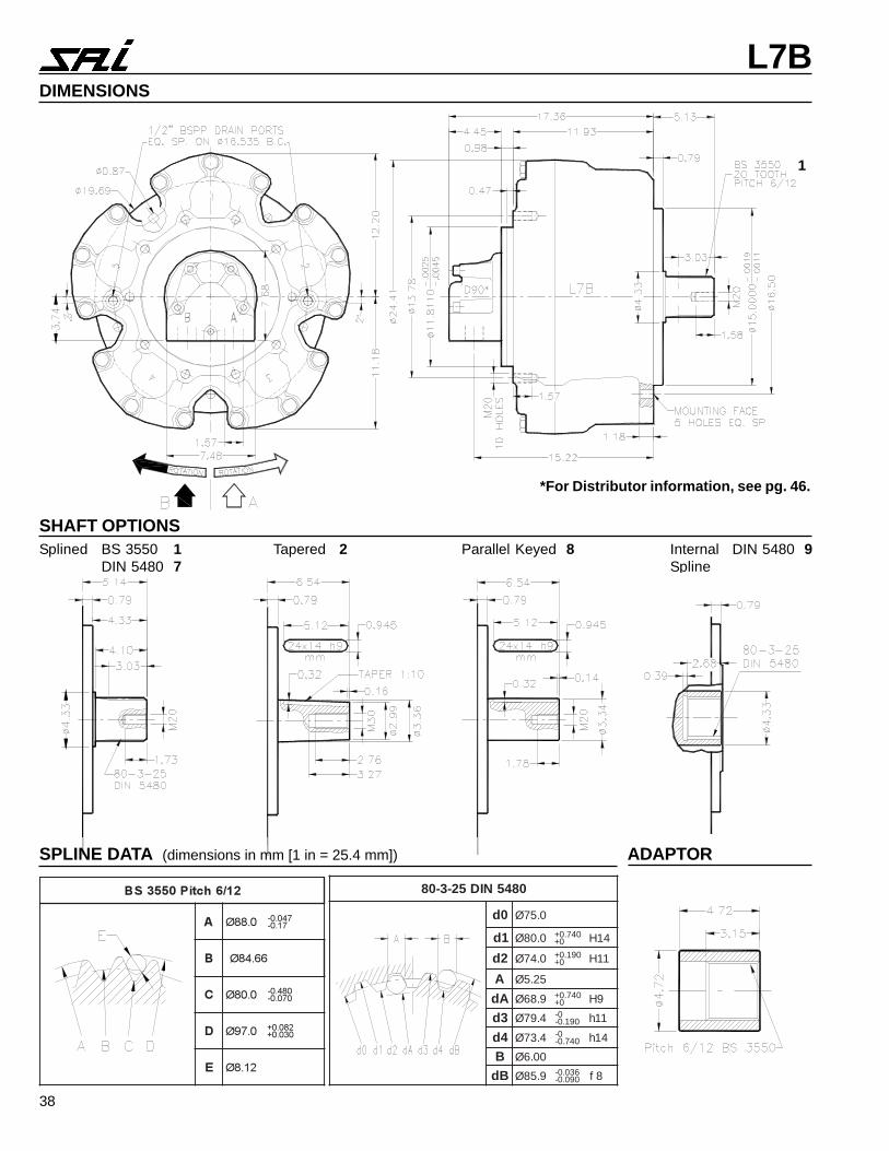
L7BDIMENSIONS
1
SHAFT OPTIONSSplined BS 3550 1
DIN 5480 7Tapered 2 Parallel Keyed 8 Internal DIN 5480 9
Spline
SPLINE DATA (dimensions in mm [1 in = 25.4 mm]) ADAPTOR
����������� �
� ����� �����������
� ����
� ����� ������������
� ���� ������� ����
� �����
*For Distributor information, see pg. 46.
0845NID52-3-08
0d 0.57Ø
1d 0.08Ø 047.0+0+ 41H
2d 0.47Ø 091.0+0+ 11H
A 52.5Ø
Ad 9.86Ø 047.0+0+ 9H
3d 4.97Ø 0-091.0- 11h
4d 4.37Ø 0-047.0- 41h
B 00.6Ø
Bd 9.58Ø 630.0-090.0- 8f
39
L7B
BEARING LIFETIME The graph refers to the motor with the standard roller bearingsNote that the average lifetime of a bearing (B50 lifetime) is approximately 5 times the B10 lifetime.
PERFORMANCE The graphs indicate the typical performance characteristics of the L7B-3000 motoroperating with mineral oil with viscosity 40 cSt at 122°F.
MECHANICAL EFFICIENCY VOLUMETRIC EFFICIENCY
STARTING AND LOW SPEED TORQUE IDLING AND BOOST PRESSURE
40
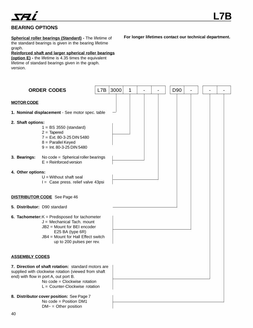
L7BBEARING OPTIONS
Spherical roller bearings (Standard) - The lifetime ofthe standard bearings is given in the bearing lifetimegraph.Reinforced shaft and larger spherical roller bearings(option E) - the lifetime is 4.35 times the equivalentlifetime of standard bearings given in the graph.version.
For longer lifetimes contact our technical department.
MOTOR CODE
1. Nominal displacement - See motor spec. table
2. Shaft options:1 = BS 3550 (standard)2 = Tapered7 = Ext. 80-3-25 DIN 54808 = Parallel Keyed9 = Int. 80-3-25 DIN 5480
3. Bearings: No code = Spherical roller bearingsE = Reinforced version
4. Other options:U = Without shaft sealI = Case press. relief valve 43psi
DISTRIBUTOR CODE See Page 46
5. Distributor: D90 standard
6. Tachometer:K = Predisposed for tachometerJ = Mechanical Tach. mountJB2 = Mount for BEI encoder
E25 BA (type 6R)JB4 = Mount for Hall Effect switch
up to 200 pulses per rev.
ASSEMBLY CODES
7. Direction of shaft rotation: standard motors aresupplied with clockwise rotation (viewed from shaftend) with flow in port A, out port B.
No code = Clockwise rotationL = Counter-Clockwise rotation
8. Distributor cover position: See Page 7No code = Position DM1DM~ = Other position
ORDER CODES L7B 3000 1 - - D90 - - -

41
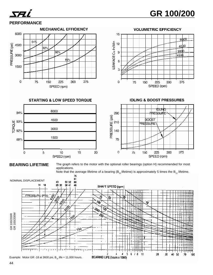
GR 100/200
SPECIFICATION DATA PERFORMANCE DATA
GR 100R / GR 100W GR 100-200R / GR 100-200W
GR 200R / GR 200W GR 200R / GR 200W
GR 200R / GR 200W
MAX. FLOW AND PRESSURE MUST NOT OCCUR SIMULTANEOUSLY.REFER TO LIFE CHART FOR B10 LIFE.
* RATIO 4.125** RATIO 5.167
��������
������������� ��
����������� ��
������� ���
�� �
�����������������
�������
�� �
�� ����� ������ � � � ���� ���� ���!
�� ���!� �"#��� #�� " ���� ���� ���!
�" �$��� �����" �"��# ���! ���� ���!
� $ � � �#��� "#�"$ ���! ���! ���!
��������
�������������� ��
����������� ��
������� ���
�� �
�����������������
�������
�� �
�� !"�� ��$��� �$� ���� ���� ���!
#� ���� �! �#� �#��! ���� ���� ���!
$! "�� �!��$! �"�#� ���� ���� ���!
!� �$� �!"�!� #!��� ���� ���� ���!
#� "!�$ �#��#� �"��� ���� ���� ���!
�� #���� �$$��� � ��� ���� ���� ���!
#� ! ��� ����#� ����" ���� �� � ���!
!� #���� ���"�!� $ �$" ���� ���� ���!
�" ! ��� ������" ����# ���! ���� ���!
��������
�������������� ��
����������� ��
������� ���
�� �
�����������������
�������
�� �
�� !"�� ��$��� �$� ���� ���� ��#�
#� ���� �! �#� �#��! ���� ���� ��#�
$! "�� �!��$! �"�#� ���� ���� ��#�
!� �$� �!"�!� #!��� ���� ���� ��#�
#� "!�$ �#��#� �"��� ���� �� � ��#�
�� #���� �$$��� � ��� �� ! ���� ��#�
#� ! ��� ����#� ����" ���! �� ! ��#�
!� #���� ���"�!� $ �$" ��!! ��!! ��#�
%���&���'
� ! � # !� "� �! �! #! !� "�
����� &���'%����(��������������
$��� �� �� �" �!� �#� ��! ��� �"�
! �#� !� �! #� "$ ��� !$� ��! ##! "��
!��$!� �
���� �� !" �$ �!� ��� "#� �! #�! �#!
!"�!� �� #! "� �# !�� ��� #"� "$� �!! !�!
#��#� " !� �! #� � �$ $�� ��� "� �$� ��!
$$��� � �� �! �� �" "# #�� $!� ��� � � �$�
���#� ��� $ #� #� "� � �$ ��� !�� ��� � �
�"�!� ��� ��# � �� !� $" # ��� �!� $�� "��
%���&���'
� ! � # !� "� �! �! #! !� "�
����� &���'%����(��������������
����� � �� �! !� �" �# ��� "!� �� $"� $#�
"#��� ��� $ #� "� �� ! �$ #�� "!� ��� !"�
����" ��� �� ���� $! �� $� � $# ��� $�� ���
#��� � " !� �! � �� !" � # ��� !��
Note: The GR Series replaces the PR Series
42
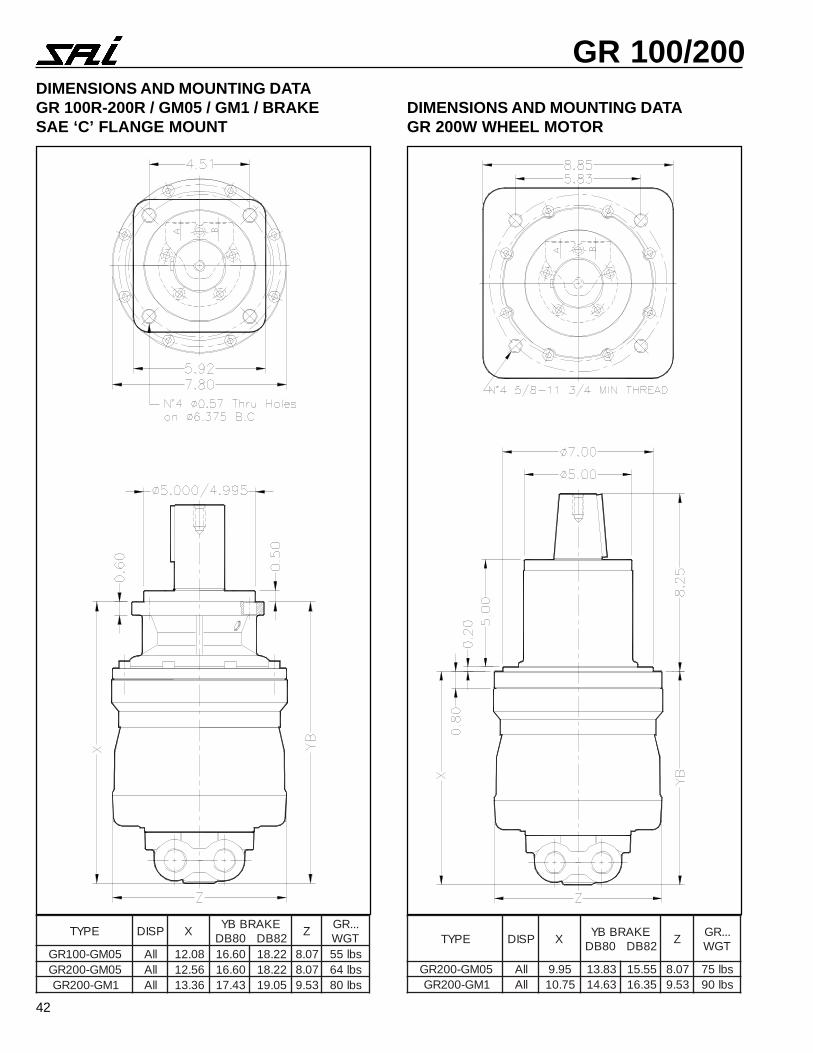
GR 100/200DIMENSIONS AND MOUNTING DATAGR 100R-200R / GM05 / GM1 / BRAKESAE ‘C’ FLANGE MOUNT
DIMENSIONS AND MOUNTING DATAGR 200W WHEEL MOTOR
EPYT PSID XEKARBBY
28BD08BDZ
...RGTGW
50MG-001RG llA 80.21 06.61 22.81 70.8 sbl5550MG-002RG llA 65.21 06.61 22.81 70.8 sbl461MG-002RG llA 63.31 34.71 50.91 35.9 sbl08
EPYT PSID XEKARBBY
28BD08BDZ
...RGTGW
50MG-002RG llA 59.9 38.31 55.51 70.8 sbl571MG-002RG llA 57.01 36.41 53.61 35.9 sbl09
43
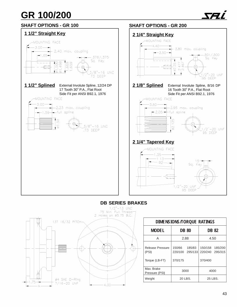
GR 100/200SHAFT OPTIONS - GR 100 SHAFT OPTIONS - GR 200
1 1/2” Straight Key 2 1/4” Straight Key
1 1/2” Splined 2 1/8” Splined
2 1/4” Tapered Key
External Involute Spline, 12/24 DP17 Tooth 30o P.A., Flat RootSide Fit per ANSI B92.1, 1976
External Involute Spline, 8/16 DP16 Tooth 30o P.A., Flat RootSide Fit per ANSI B92.1, 1976
SGNITAREUQROT/SNOISNEMID
LEDOM 08BD 28BD
A 88.2 05.4
erusserPesaeleR)ISP(
)TF-BL(euqroT
38/58166/051331/592001/022
571/073
002/581851/051513/592042/022
004/073
ekarB.xaM)ISP(erusserP
0003 0004
thgieW .SBL02 .SBL52
DB SERIES BRAKES
44
GR 100/200
BEARING LIFETIME The graph refers to the motor with the optional roller bearings (option H) recommended for mostapplications.Note that the average lifetime of a bearing (B50 lifetime) is approximately 5 times the B10 lifetime.
PERFORMANCE
NOMINAL DISPLACEMENT
GR
100
/200
RG
R 1
00/2
00W
Example: Motor GR -18 at 3600 psi, B10 life = 11,000 hours.
45
GR 100/200
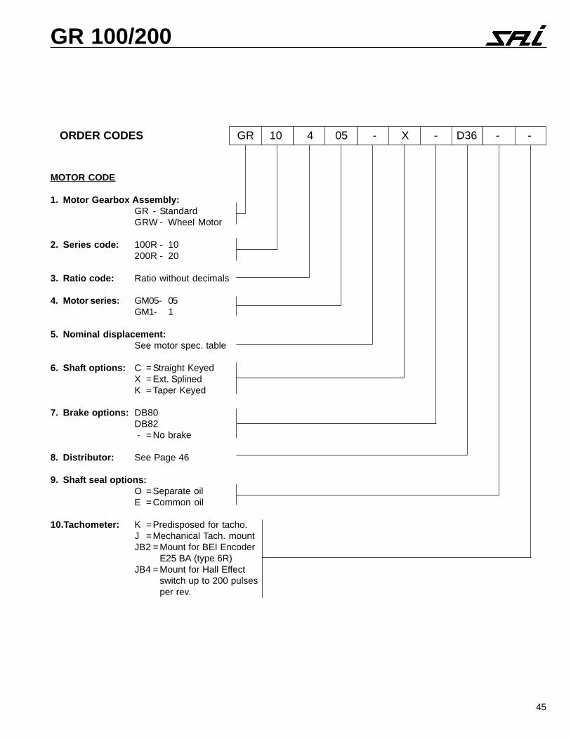
MOTOR CODE
1. Motor Gearbox Assembly:GR - StandardGRW - Wheel Motor
2. Series code: 100R - 10200R - 20
3. Ratio code: Ratio without decimals
4. Motor series: GM05- 05GM1- 1
5. Nominal displacement:See motor spec. table
6. Shaft options: C = Straight KeyedX = Ext. SplinedK = Taper Keyed
7. Brake options: DB80DB82 - = No brake
8. Distributor: See Page 46
9. Shaft seal options:O = Separate oilE = Common oil
10.Tachometer: K = Predisposed for tacho.J = Mechanical Tach. mountJB2 = Mount for BEI Encoder
E25 BA (type 6R)JB4 = Mount for Hall Effect
switch up to 200 pulsesper rev.
ORDER CODES GR 10 4 05 - X - D36 - -
46
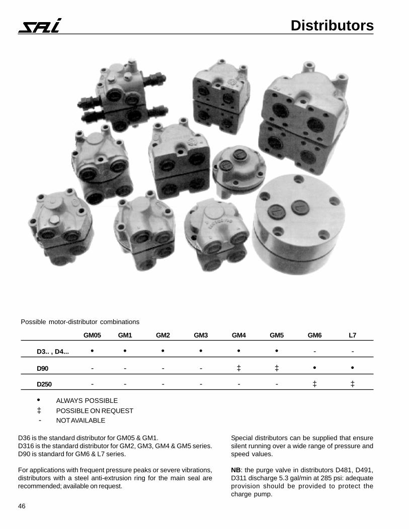
Distributors
Possible motor-distributor combinations
GM05 GM1 GM2 GM3 GM4 GM5 GM6 L7
D3.. , D4... • • • • • • - -
D90 - - - - ‡ ‡ • •
D250 - - - - - - ‡ ‡
• ALWAYS POSSIBLE
‡ POSSIBLE ON REQUEST - NOT AVAILABLE
D36 is the standard distributor for GM05 & GM1.D316 is the standard distributor for GM2, GM3, GM4 & GM5 series.D90 is standard for GM6 & L7 series.
For applications with frequent pressure peaks or severe vibrations,distributors with a steel anti-extrusion ring for the main seal arerecommended; available on request.
Special distributors can be supplied that ensuresilent running over a wide range of pressure andspeed values.
NB: the purge valve in distributors D481, D491,D311 discharge 5.3 gal/min at 285 psi: adequateprovision should be provided to protect thecharge pump.
47
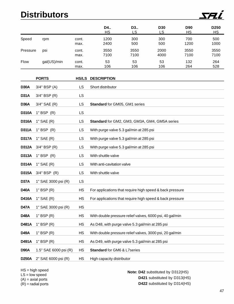
DistributorsD4.. D3.. D30 D90 D250HS LS LS HS HS
Speed rpm cont. 1200 300 300 700 500max. 2400 500 500 1200 1000
Pressure psi cont. 3550 3550 2000 3550 3550max. 7100 7100 4000 7100 7100
Flow gal(US)/min cont. 53 53 53 132 264max. 106 106 106 264 528
HS = high speedLS = low speed(A) = axial ports(R) = radial ports
PORTS HS/LS DESCRIPTION
D30A 3/4" BSP (A) LS Short distributor
D31A 3/4" BSP (R) LS
D36A 3/4" SAE (R) LS Standard for GM05, GM1 series
D310A 1" BSP (R) LS
D316A 1" SAE (R) LS Standard for GM2, GM3, GM3A, GM4, GM5A series
D311A 1" BSP (R) LS With purge valve 5.3 gal/min at 285 psi
D317A 1" SAE (R) LS With purge valve 5.3 gal/min at 285 psi
D312A 3/4" BSP (R) LS With purge valve 5.3 gal/min at 285 psi
D313A 1" BSP (R) LS With shuttle valve
D314A 1" SAE (R) LS With anti-cavitation valve
D315A 3/4" BSP (R) LS With shuttle valve
D37A 1" SAE 3000 psi (R) LS
D40A 1" BSP (R) HS For applications that require high speed & back pressure
D416A 1" SAE (R) HS For applications that require high speed & back pressure
D47A 1" SAE 3000 psi (R) HS
D48A 1" BSP (R) HS With double pressure relief valves, 6000 psi, 40 gal/min
D481A 1" BSP (R) HS As D48, with purge valve 5.3 gal/min at 285 psi
D49A 1" BSP (R) HS With double pressure relief valves, 3000 psi, 20 gal/min
D491A 1" BSP (R) HS As D49, with purge valve 5.3 gal/min at 285 psi
D90A 1.5" SAE 6000 psi (R) HS Standard for GM6 & L7series
D250A 2" SAE 6000 psi (R) HS High capacity distributor
Note: D42 substituted by D312(HS)
D421 substituted by D313(HS)
D422 substituted by D314(HS)
48
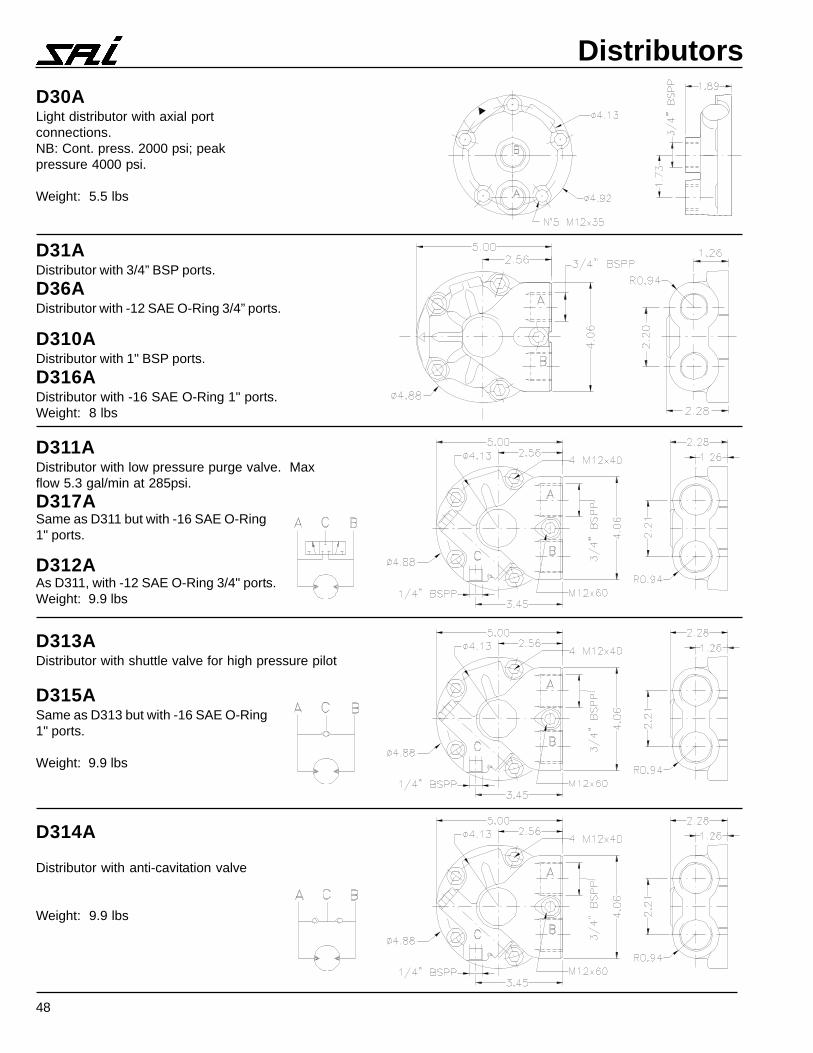
DistributorsD30ALight distributor with axial portconnections.NB: Cont. press. 2000 psi; peakpressure 4000 psi.
Weight: 5.5 lbs
D311ADistributor with low pressure purge valve. Maxflow 5.3 gal/min at 285psi.
D317ASame as D311 but with -16 SAE O-Ring1" ports.
D312AAs D311, with -12 SAE O-Ring 3/4" ports.Weight: 9.9 lbs
D313ADistributor with shuttle valve for high pressure pilot
D315ASame as D313 but with -16 SAE O-Ring1" ports.
Weight: 9.9 lbs
D314A
Distributor with anti-cavitation valve
Weight: 9.9 lbs
D31ADistributor with 3/4” BSP ports.
D36ADistributor with -12 SAE O-Ring 3/4” ports.
D310ADistributor with 1" BSP ports.
D316ADistributor with -16 SAE O-Ring 1" ports.Weight: 8 lbs
49
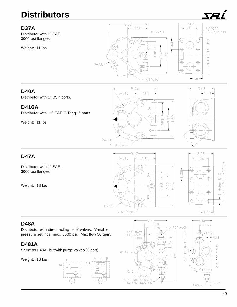
DistributorsD37ADistributor with 1” SAE,3000 psi flanges
Weight: 11 lbs
D40ADistributor with 1” BSP ports.
D416ADistributor with -16 SAE O-Ring 1” ports.
Weight: 11 lbs
D47A
Distributor with 1” SAE,3000 psi flanges
Weight: 13 lbs
D48ADistributor with direct acting relief valves. Variablepressure settings, max. 6000 psi. Max flow 50 gpm.
D481ASame as D48A, but with purge valves (C port).
Weight: 13 lbs
50
Distributors
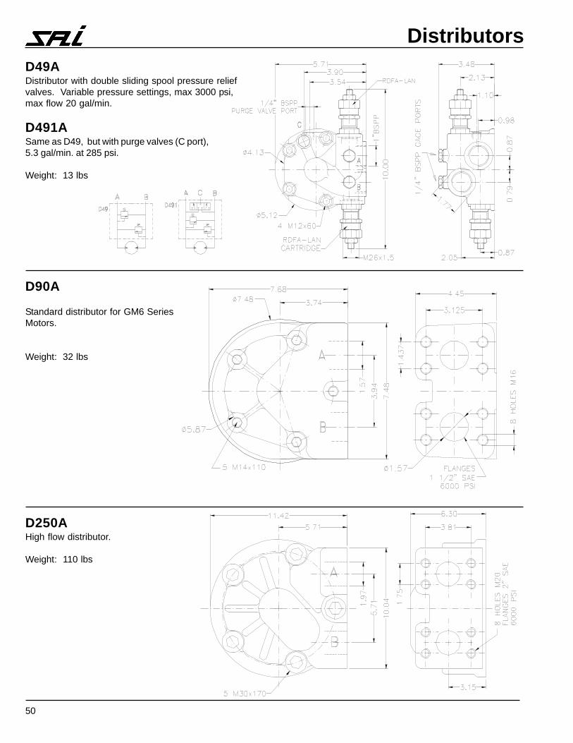
D250AHigh flow distributor.
Weight: 110 lbs
D90A
Standard distributor for GM6 SeriesMotors.
Weight: 32 lbs
D49ADistributor with double sliding spool pressure reliefvalves. Variable pressure settings, max 3000 psi,max flow 20 gal/min.
D491ASame as D49, but with purge valves (C port),5.3 gal/min. at 285 psi.
Weight: 13 lbs
51
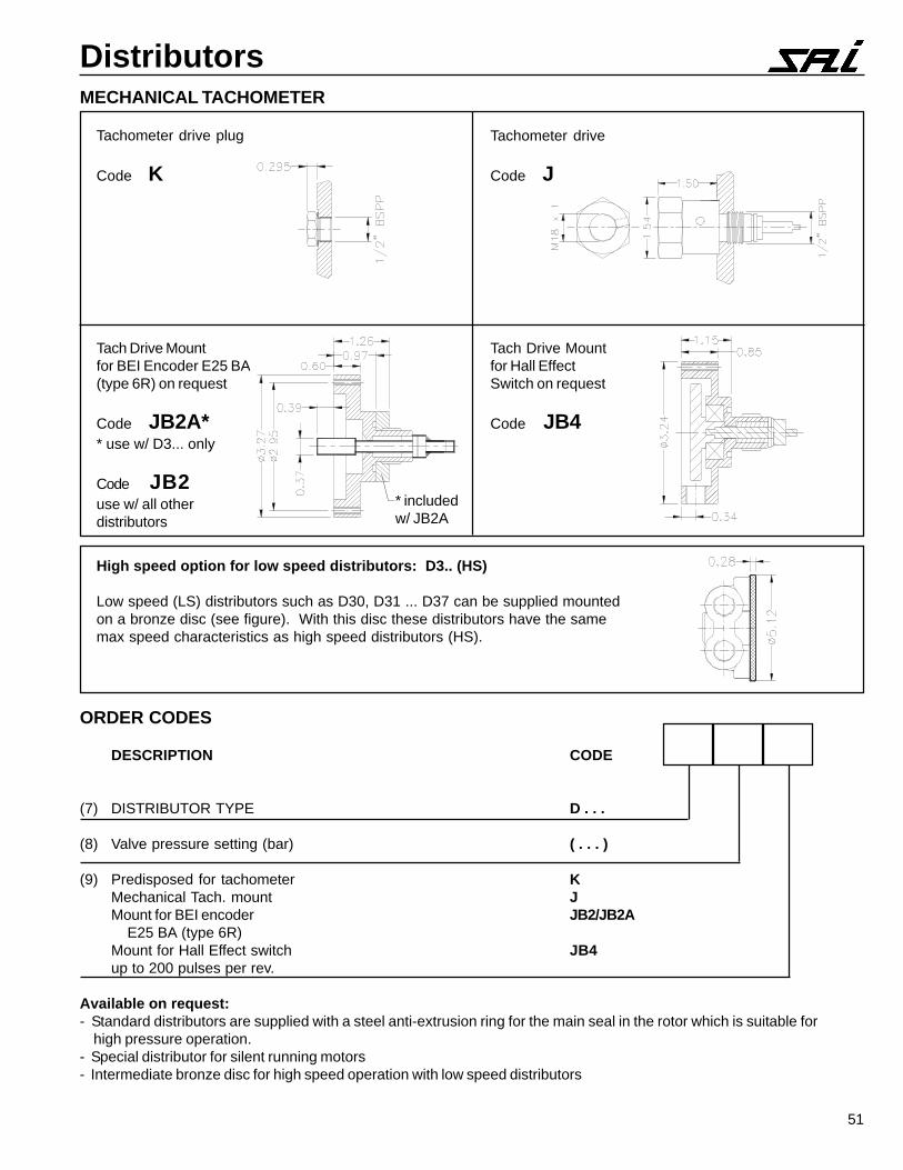
DistributorsMECHANICAL TACHOMETER
Tachometer drive plug
Code K
Tachometer drive
Code J
Tach Drive Mountfor BEI Encoder E25 BA(type 6R) on request
Code JB2A** use w/ D3... only
Code JB2use w/ all otherdistributors
Tach Drive Mountfor Hall EffectSwitch on request
Code JB4
High speed option for low speed distributors: D3.. (HS)
Low speed (LS) distributors such as D30, D31 ... D37 can be supplied mountedon a bronze disc (see figure). With this disc these distributors have the samemax speed characteristics as high speed distributors (HS).
ORDER CODES
DESCRIPTION CODE
(7) DISTRIBUTOR TYPE D . . .
(8) Valve pressure setting (bar) ( . . . )
(9) Predisposed for tachometer KMechanical Tach. mount JMount for BEI encoder JB2/JB2A E25 BA (type 6R)Mount for Hall Effect switch JB4up to 200 pulses per rev.
Available on request:- Standard distributors are supplied with a steel anti-extrusion ring for the main seal in the rotor which is suitable for high pressure operation.- Special distributor for silent running motors- Intermediate bronze disc for high speed operation with low speed distributors
* includedw/ JB2A
52
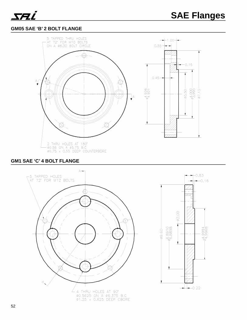
SAE FlangesGM05 SAE ‘B’ 2 BOLT FLANGE
GM1 SAE ‘C’ 4 BOLT FLANGE


