

2/02
SCHOLARLY PAPER SUBMISSION/APPROVAL FORM Systems Engineering (ENSE)
This is to verify that Kevin Luft has (printed name of student)
submitted a scholarly paper for completion of degree requirements for the non-thesis option for the
MS degree in systems engineering. Our signatures below indicate that we have read the
scholarly paper and approve it as submitted/with minor modifications.
Printed name/Academic advisor Signature (date)
Printed name/Second reader Signature (date)
NOTE: A COPY OF THE APPROVED SCHOLARLY PAPER MUST BE ATTACHED TO THIS FORM PRIOR TO SUBMISSION TO THE EDUCATION OFFICE

Date: ____5/29/2006________
5 7 2 __ 3 1 __ 6 8 2 9 Luft, Kevin___________________________________ Student ID Number Print Full Name (Last, First, Middle)
M S S E
2155 Scott’s Crossing Ct. Apt. 101 ________ Graduate Program Initial Term (GEMS use only) Address Annapolis, MD 21401-8260_________________________ Degree Sought: Master of Science_____________________ City, State, ZIP [email protected]_____________________________ (443) 454-4240________________________________ Email Address (Area Code) Telephone The student named above is a candidate for the Master’s degree in ________Systems Engineering__________ without thesis, and who seeks the degree at the _____Summer 2006_______(semester/year) Commencement has met all the requirements of the graduate program including (if applicable): Seminar or Research Papers Date Completed Multidisciplinary System Design Optimization 7/27/2006
Comprehensive Examinations Date Completed
ENSE 623 – Systems Engineering Design Project Final Exam 12/17/2003
________________________________________________________ ______________________________________________ Advisor (Print Name then Sign) Date Telephone extension and Email Address ________________________________________________________ ______________________________________________ Director of Graduate Program (Print Name then Sign) Date Telephone extension and Email Address Please return this form to:
Graduate Enrollment Management Services 2123 Lee Building • University of Maryland
College Park, Maryland 20742-5121 301.405.0376 Voice • 301.314.9305 FAX
UNIVERSITY OF MARYLAND, COLLEGE PARK Graduate Enrollment Management Services
CERTIFICATION OF MASTER’S DEGREE WITHOUT THESIS
Revised 9/01
ABSTRACT
Title of Document: MULTI-DISCIPLINARY SYSTEM DESIGN
OPTIMIZATION Kevin Luft
Master of Engineering Management Old Dominion University, Virginia Master of Science, Systems Engineering, 2006 University of Maryland, College Park
Directed By: Dr. Mark Austin
Department of Civil and Environmental Engineering and Institute for Systems Research University of Maryland, College Park
Multidisciplinary System Design Optimization is a new name for a time tested process that grows increasingly complicated as the size and complexity of modern systems evolve. Derived from the Multidisciplinary Design Optimization techniques of the aerospace industry and benefiting from decades of experience and evolution, its purpose is to achieve an “optimal” design in a more general sense by considering additional aspects of the system development lifecycle. As the concept of an optimal design continues to evolve—and as systems grow larger, more complicated and interrelated—the processes for finding optimal designs will evolve. This adaptation increasingly requires the input of diverse teams of experts in far flung locations and utilizes the latest technologies. Using these techniques to make appropriate tradeoffs and find an optimal design—in both objective and subjective contexts—is an essential but difficult task.
i

MULTI-DISCIPLINARY SYSTEM DESIGN OPTIMIZATION
By
Kevin Luft
Scholarly paper submitted to the Faculty of the Graduate School of the University of Maryland, College Park, in partial fulfillment
of the requirements for the degree of Master of Science
2006 Advisor: Dr. Mark Austin
ii

© Copyright by Kevin Luft
2006
iii

Table of Contents
Table of Contents......................................................................................................... iv 1. Introduction.............................................................................................................. 1 2. The System Development Process: An Overview................................................... 2
Modeling and Simulation........................................................................................ 4 Decomposition ........................................................................................................ 8 Exploring the Design Space.................................................................................... 9 Quantitative Optimization Techniques ................................................................. 10
3. Multi-Disciplinary System Design Optimization .................................................. 12 Background........................................................................................................... 12 Fundamental Approaches to MSDO..................................................................... 15 Tools to Support MSDO ....................................................................................... 21 Challenges............................................................................................................. 24
4. Conclusion ............................................................................................................. 26 Bibliography ............................................................................................................... 27
iv
1. Introduction
Multidisciplinary System Design Optimization (MSDO) is a new name for a
time tested process that grows increasingly complicated as the size and complexity of
modern systems evolve. As systems become ever larger, more complex, and
interrelated, new design techniques must evolve to enable the system development
process. Concurrent, multi-disciplinary, computer aided design and manufacturing
will continue to become increasingly necessary. Using these techniques to make
appropriate tradeoffs and find an optimal design—in both objective and subjective
contexts—is an essential but difficult task.
The design process is both qualitative and quantitative.1 System design is
both art and science—creative, unstructured activities must mesh with rigorous,
quantitative methodologies to achieve an optimal design from a system lifecycle
perspective. As needs changed over time, the focus on maximum performance was
“superseded by a new quest for a balance among performance, life-cycle cost,
reliability, maintainability, vulnerability, and other ‘-ilities.’”2 Government and
industry are placing greater emphasis on the need to implement high quality, efficient
processes that can deliver systems quickly, just-in-time for their intended use.
But achieving a balanced design for a large, complex system requires the
input and expertise of large teams of domain experts, most of whom have difficulty
communicating and collaborating with other specialists.
1 AIAA Technical Committee on Multidisciplinary Design Optimization, White Paper on Current State of the Art (January 15, 1991), Foreword. < http://endo.sandia.gov/AIAA_MDOTC/sponsored /aiaa_paper.html> 2 Ibid.
1

2. The System Development Process: An Overview
The design process—when distilled to its simplest form—is only three steps:
analysis, synthesis, and evaluation. The process is sequential, cyclical or iterative,
and recursive. More specifically, the design process includes conceptual design,
preliminary design, and detailed design, followed by a production and construction
phase. In a systems engineering context, the general phases are further specified to
include planning and analysis, systems (logical) architecting, detailed (physical)
design, and build and test. Throughout the process, the desired end state or goals
must be clear, and the designers must maintain some idea of their current progress
toward those goals.
The Institute for Systems Research (ISR) at the University of Maryland,
College Park (UMCP) has completed considerable research on the system
development process with partners in industry and government as part of various
programs, and as a National Science Foundation Engineering Research Center. The
results indicate a number of problems with current system development techniques
commonly used throughout industry and point to a number of necessary
improvements. Some problems with current processes include poorly defined
relationship between design abstractions; difficulty evaluating the complete design
space due to its size and complexity; premature commitment to technologies; poor
support for design changes, which become increasingly difficult and problematic as
the process continues; lack of a standardized modeling technique; infrequent reuse of
2

previously existing knowledge, designs, and components; and poor support for
product line development.3
ISR advocates the use of formal models, abstraction and decomposition to
mitigate these challenging problems. These techniques allow design formalization
and early detection of errors, permit separation of design concerns, support synthesis
from modular components, and encourage reuse and tool support at all levels of
abstraction.4 Perhaps the single most important finding of ISR’s research is that
standardized modeling tools must be developed to enable proper system
decomposition and facilitate communication between disciplines. Standardized
modeling tools also encourage appropriate abstraction, which is essential to design in
general, and to team-based design in particular.
The Unified Modeling Language (UML) is poised to be this standard.
Modularity—decomposing systems into distinct modules with clearly defined
interfaces—is another key concept that can help mitigate many of the shortcomings of
the current system development lifecycle (SDLC). Finally, validation and
verification processes must be spread across all phases of the SDLC to make change
simpler and less expensive and to identify problems earlier. This means moving
verification processes into both the logical and physical design phases, and
performing validation throughout the lifecycle, instead of just at the end.
3 Mark Austin, Systems Engineering Principles, (College Park, MD: Course Notes, Fall 2005), 29-36. 4 Ibid, 37-45.
3
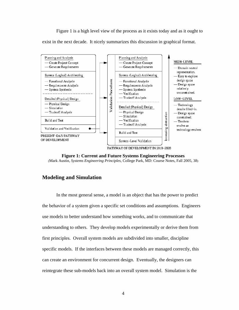
Figure 1 is a high level view of the process as it exists today and as it ought to
exist in the next decade. It nicely summarizes this discussion in graphical format.
Figure 1: Current and Future Systems Engineering Processes (Mark Austin, Systems Engineering Principles, College Park, MD: Course Notes, Fall 2005, 38)
Modeling and Simulation
In the most general sense, a model is an object that has the power to predict
the behavior of a system given a specific set conditions and assumptions. Engineers
use models to better understand how something works, and to communicate that
understanding to others. They develop models experimentally or derive them from
first principles. Overall system models are subdivided into smaller, discipline
specific models. If the interfaces between these models are managed correctly, this
can create an environment for concurrent design. Eventually, the designers can
reintegrate these sub-models back into an overall system model. Simulation is the
4

process of exercising a model to predict system response given a specific set of
inputs.5
The distinction between different types of models—and between analysis and
design models in particular—is made clear by Papalambros and Wilde in Principles
of Optimal Design.6 Analysis models are simply descriptive models of some aspect
of an overall design—a grouping of variables, parameters, and constants, for
example. The results of these analyses are combined to form a design model, which
is predictive. Both types of models are necessary in MSDO. Analysis and design
models can be used on subsystems by discipline-specific teams and during overall
system integration by multidisciplinary teams.
The Unified Modeling Language (UML) provides a powerful set of tools for
use in creating both analysis and design models. It is the cornerstone of modeling
within the Systems Engineering program at UMCP and an industry standard within
the software development community. Researchers are currently developing
industrial software to perform automated transformations between UML models and
can already demonstrate some limited transformations.7 Model transformations
support several techniques that hold promise on multiple levels of the system
development process.
The first technique—model checking—makes a determination about the
consistency of two diagrams, generally at a lower level of abstraction. At higher
5 Oliver de Weck and Karen Wilcox, Multidisciplinary System Design Optimization Lecture Notes (Cambridge, MA: MIT Open CourseWare, Spring 2004), Session 3, 4. < http://ocw.mit.edu/OcwWeb /Aeronautics-and -Astronautics/16-888Spring-2004/LectureNotes/index.htm> 6 Panos Y. Papalambros, and Douglas J. Wilde, Principles of Optimal Design. (New York, NY: Cambridge University Press, 2000), 6. 7 P. Selonen, K. Koskimies, M. Sakkinen, M, “Transformations between UML Diagrams,” Journal of Database Management 14 (July-September 2003), 38.
5
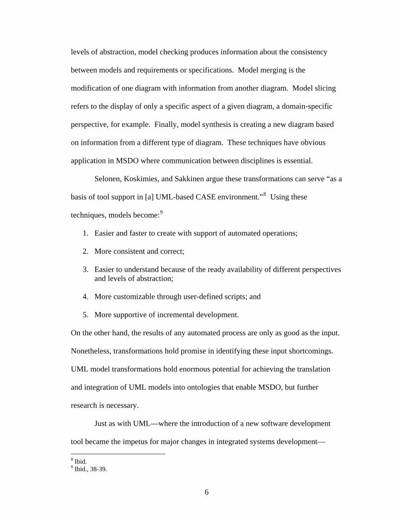
levels of abstraction, model checking produces information about the consistency
between models and requirements or specifications. Model merging is the
modification of one diagram with information from another diagram. Model slicing
refers to the display of only a specific aspect of a given diagram, a domain-specific
perspective, for example. Finally, model synthesis is creating a new diagram based
on information from a different type of diagram. These techniques have obvious
application in MSDO where communication between disciplines is essential.
Selonen, Koskimies, and Sakkinen argue these transformations can serve “as a
basis of tool support in [a] UML-based CASE environment.”8 Using these
techniques, models become:9
1. Easier and faster to create with support of automated operations; 2. More consistent and correct; 3. Easier to understand because of the ready availability of different perspectives
and levels of abstraction; 4. More customizable through user-defined scripts; and 5. More supportive of incremental development.
On the other hand, the results of any automated process are only as good as the input.
Nonetheless, transformations hold promise in identifying these input shortcomings.
UML model transformations hold enormous potential for achieving the translation
and integration of UML models into ontologies that enable MSDO, but further
research is necessary.
Just as with UML—where the introduction of a new software development
tool became the impetus for major changes in integrated systems development— 8 Ibid. 9 Ibid., 38-39.
6

advances in software performance modeling and model checking stand to further
revolutionize systems engineering. Engineers would achieve huge gains if they are
able to convert all UML representations of system structure and behavior into an
integrated software model and automatically check it as part of the system
verification and validation process.
By accomplishing this translation early in the development cycle, the many
benefits of system testing will affect all following stages of system development.
Inconsistencies in the software model will translate back into UML-based models or
textual (or other) descriptions. Furthermore, it may be possible for the process to
generate counter examples, an ability that already exists in several software model
checking systems.10 This feedback will allow engineers to correct discrepancies. In
this manner, the UML system model and associated requirements can be refined and a
test plan developed that incorporates various verification and validation tasks as early
as appropriate.
This could be a powerful tool, especially in connection with the development
of automated requirement traceability management and display software within ISR
and with the continued development of the semantic web. The ultimate, long-term
goal is an integrated CASE environment that is an order of magnitude more useful
and user friendly than those currently available.
10 W. Adrion, M. Branstaqd, & J. Cherniavsky, “Validation, Verification, and Testing of Computer Systems,” Computing Surveys 14 (June 1982); W. Chan et al., “Model Checking Large Software Specifications,” IEEE Transaction s on Software Engineering, 24 (July 1998).
7
Decomposition
As discussed, engineers and designers develop models experimentally or
derive them from first principles. If the system is new and they have no similar
experience on which to base decisions, a different approach is necessary. In this case,
the system might be decomposed into modules that are discipline specific or have
some other logical relationship. For example, a certain software package may be well
suited to handle certain parts of the system—even if traditionally managed by
different disciplines—which can then be allocated to the same module for ease of
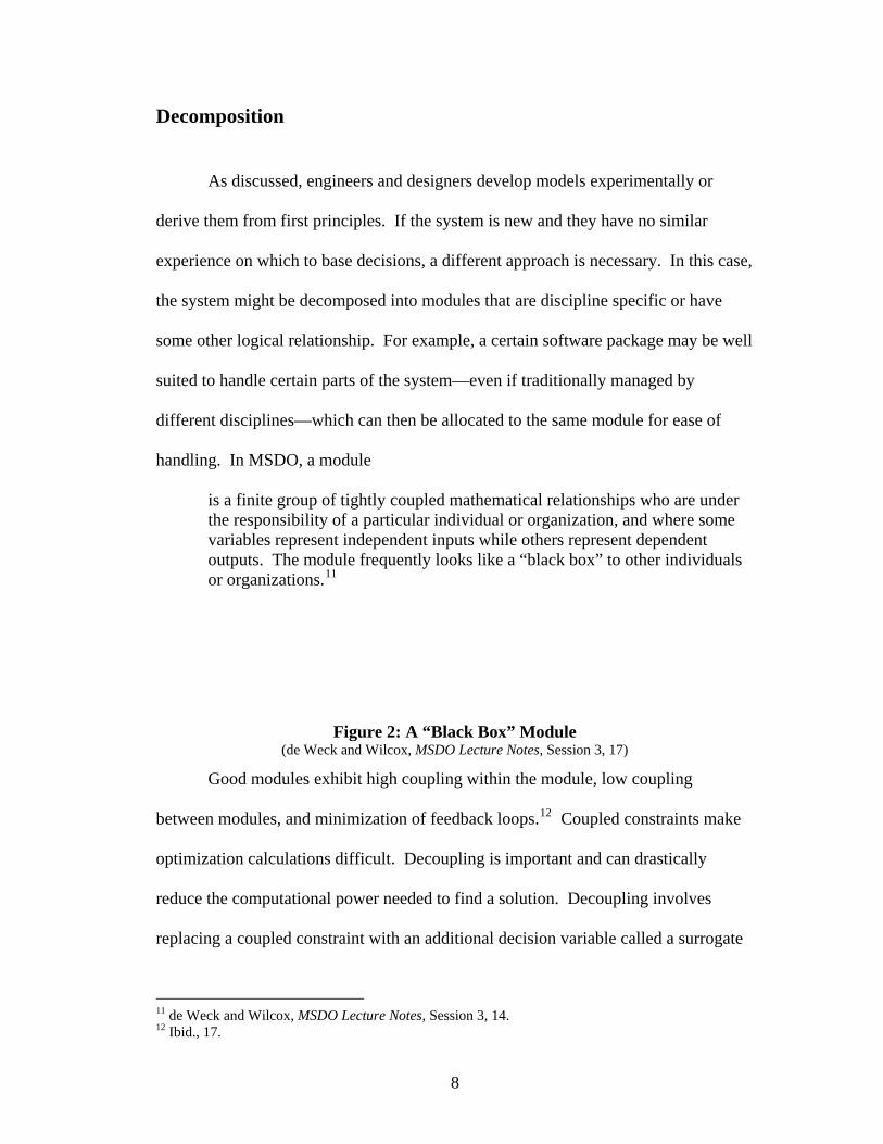
handling. In MSDO, a module
is a finite group of tightly coupled mathematical relationships who are under the responsibility of a particular individual or organization, and where some variables represent independent inputs while others represent dependent outputs. The module frequently looks like a “black box” to other individuals
11
Good modules exhi
or organizations.
bit high coupling within the module, low coupling
between modules, and minimization of feedback loops. Coupled constraints make
optimization calculations difficult. Decoupling is important and can drastically
reduce the computational power needed to find a solution. Decoupling involves
replacing a coupled constraint with an additional decision variable called a surrogate
Figure 2: A “Black Box” Module (de Weck and Wilcox, MSDO Lecture Notes, Session 3, 17)
12
11 de Weck and Wilcox, MSDO Lecture Notes, Session 3, 14. 12 Ibid., 17.
8

variable. Regardless of how the system is decomposed, module inputs and outputs—
or interfaces—must be strictly defined to allow any sort of concurrent engineering
work to occur.
After a system is decomposed into logical and physical models, it must then
be recomposed into a whole by ordering and arranging the modules to produce a full
system model. Combining these modules into an overall system model is not easy.
The Design Structure Matrix or N2 Matrix are excellent tools that can assist systems
engineers in these processes. Benchmarking and validating the component modules
or simulations against known cases or empirical data improves their predictive power
and usefulness. Further, benchmarking and validating the full system model—as a
collection of interconnected modules—is also essential.
Exploring the Design Space
There are many different techniques for exploring the design space. Design of
experiments is a group of statistical tools needed to accomplish a comprehensive
evaluation of the design space. It is particularly useful for unique problems with little
precedent. This approach is typically used before running an optimization because it
allows the designer to predetermine an achievable range of variables and objectives,
to limit the scope of the optimization problem to make it feasible.
Initially, a full or fractional factorial approach might be most appropriate to
sample the design space. The full factorial approach is comprehensive, but the
number of experiments grows exponentially as the number of factors and levels for
those factors increase. An alternative is to use a fractional factorial design, which
9
limits the number of experiments but can potentially obscure relationships. Another
alternative is to use an orthogonal array to select a specific subset of a full factorial
experiment where the factors are orthogonal. This approach will not capture all
interactions, but is efficient and balanced.13 The results of these techniques are
measures of the main effect that each factor has on the overall objective and the
interactions between factors.
Once the design space has been explored and a feasible problem bounded,
optimization techniques can assist designers in identifying and evaluating potential
solutions. Defining what “optimal” means in terms of potential solutions will depend
on a number of factors, some scientific, some organizational.
Quantitative Optimization Techniques
The goal of optimization is to achieve some objective function by changing
design variables, given a series of parameters and constraints. The objective function
is the system response or other characteristic the designer is attempting to optimize.
Mathematically, this means either maximizing or minimizing a function. Designers
adjust design variables to achieve the desired effect on the objective. Parameters are
fixed quantities affecting the objective function that are outside the control of the
designer. Examples include natural laws and previously fixed design variables.
Constraints represent the boundaries of the design space; they are used to confine the
search for the optimal solution. This means a particular solution may only be locally
optimal—that is, optimal only within the region of the constrained design space—
13 de Weck and Wilcox, MSDO Lecture Notes, Session 5, 15.
10

while an unexamined globally optimal solution might also exist just outside the local
region. The problem of verifying that a particular solution is indeed a globally
optimal solution is the focus of significant research. Figure 3 presents the basic
A detailed discussion of the numerous math
formulation of a simplified optimization problem.
es available
today f
lated
of the
till
Figure 3: A Basic Optimization Problem (de Weck and Wilcox, MSDO Lecture Notes, Session 2, 20)
ematical techniqu
or optimization is beyond the scope of this paper. De Weck and Wilcox
briefly cover many of these techniques—including numerical optimization, simu
annealing, genetic algorithms, particle swarm optimization, and goal programming—
in their course at MIT.14 Each has unique advantages and disadvantages. Specialists
have devoted considerable study to determining which techniques are best in
particular situations and developing frameworks for the consistent application
appropriate techniques. One other key point is that an optimal design is only optimal
“within the scope of the mathematical model describing it and the inevitable
subjective judgment of the modeler.”15 In other words, a human being must s
interpret the results of any optimization.
14 The materials for this course at MIT are an excellent resource; they are freely available as part of MIT’s Open Courseware program and were used extensively in this paper. 15 Papalambros and Wilde, Principles of Optimal Design, 1.
11
3. Multi-Disciplinary System Design Optimization
Background
MSDO in the context of this paper has its origins in the Multidisciplinary
Design Optimization (MDO) techniques developed by the aerospace industry over the
last 40 years. MDO presumably originated in the aerospace industry because of the
tight coupling between a handful of disciplines, including aerodynamics, structures,
materials, and the like. In the very early days, a single designer meshed all these
concerns into a practical body of knowledge gained largely through experience and
focused through the lens of a solid engineering background. Research developments
in the separate fields during the 1930s complicated the picture, forcing the senior
design engineer to become an early version of today’s systems engineer. He used
practical judgment to coordinate the concerns of many specialists in order to achieve
a working, flying design.
During the late 60s and early 70s, computers began to take an active role in
design. The Department of Defense (DoD) changed its procurement policies to focus
on balanced designs that achieved an optimal mix of performance, cost,
manufacturability, reliability, and maintainability, among other considerations. This
shift was primarily due to the rapid growth in the number of design requirements and
emphasis on reducing life-cycle cost, which is largely determined during the
conceptual and advanced development phases of the traditional system development
process. In fact, Boeing claims that it incurred fully 85% of the determined life-cycle
12
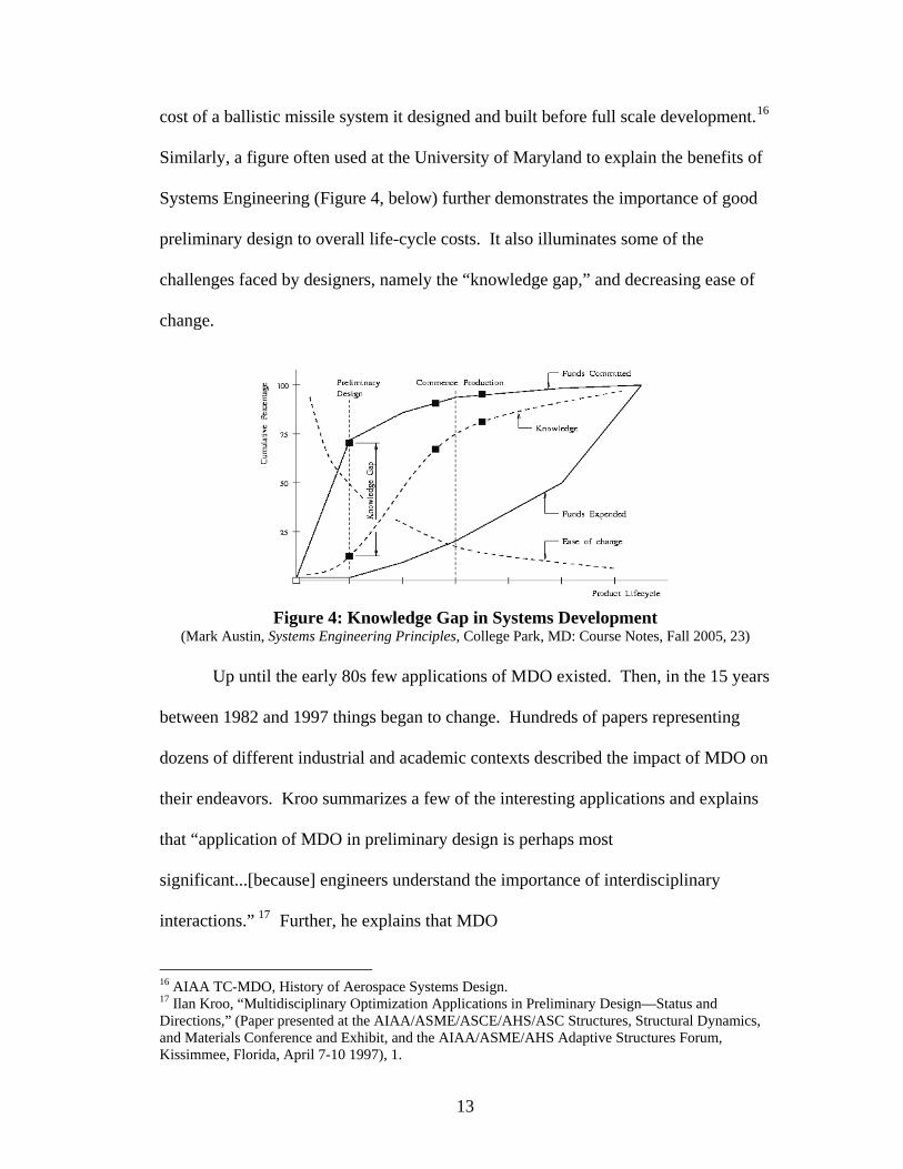
cost of a ballistic missile system it designed and built before full scale development.16
igure 4, below) further demonstrates the importance of good
preliminary design to overall life-cycle costs. It also illuminates some of the
challen of
0s few applications of MDO existed. Then, in the 15 years
betwee
nd explains
17
Similarly, a figure often used at the University of Maryland to explain the benefits of
Systems Engineering (F
ges faced by designers, namely the “knowledge gap,” and decreasing ease
change.
Up until the early 8
Figure 4: Knowledge Gap in Systems Development (Mark Austin, Systems Engineering Principles, College Park, MD: Course Notes, Fall 2005, 23)
n 1982 and 1997 things began to change. Hundreds of papers representing
dozens of different industrial and academic contexts described the impact of MDO on
their endeavors. Kroo summarizes a few of the interesting applications a
that “application of MDO in preliminary design is perhaps most
significant...[because] engineers understand the importance of interdisciplinary
interactions.” Further, he explains that MDO
16 AIAA TC-MDO, History of Aerospace Systems Design. 17 Ilan Kroo, “Multidisciplinary Optimization Applications in Preliminary Design—Status and Directions,” (Paper presented at the AIAA/ASME/ASCE/AHS/ASC Structures, Structural Dynamics, and Materials Conference and Exhibit, and the AIAA/ASME/AHS Adaptive Structures Forum, Kissimmee, Florida, April 7-10 1997), 1.
13

is a formalization of the preliminary design process, enforcing rational trade-
encourages careful and explicit problem formulation…and can reduce the 18
areas for
offs rather than ad-hoc or historically-mandated priorities. The MDO process
likelihood of costly redesign later in the product development cycle.
As emphasis shifted to productivity, quality, and global competitiveness
across industries during the 80s and 90s, the DoD continued to revise its acquisition
processes and drive change in the aerospace industry—and across the defense
industry in general. In an effort to align traditionally disparate design disciplines and
organize the growing MDO movement into a coherent force, the American Institute
of Aeronautics and Astronautics (AIAA) formed a Technical Committee on
Multidisciplinary Design Optimization (TC-MDO) in 1991. Their self-stated purpose
was to focus “diverse disciplinary design technologies…into a concerted action” to
improve the performance, manufacturability, serviceability, and life-cycle cost
effectiveness of aerospace vehicles.19 They intended to achieve this goal by
reviewing then recent advancements in mathematically based MDO and suggesting
further research.
aft
.” 20 In 1995,
Balling and Sobieszczanski-Sobieski published a unified overview of MDO,
consolidating nomenclature and discussing the primary techniques of the rapidly
In 1990, Sobieszczanski-Sobieski published what many consider the seminal
work on MDO. He advocated the adaptation of a formal systems approach to aircr
design, enabling organizations to “exploit interdisciplinary synergism while dividing
the large design task into smaller, concurrently executable tasks, without being
limited to formalism of the top-down, hierarchical decomposition
18 AIAA TC-MDO, History of Aerospace Systems Design. 19 Ibid. 20 Jaorslaw Sobieszczanski-Sobieski, “Sensitivity Analysis and Multidisciplinary Optimization for
rcraft 27 (December, 1990). Aircraft Design: Recent Advances and Results,” Journal of Ai
14

developing field.21 This signaled the legitimacy of MDO and emphasized its
practical importance.
More recently, concurrent engineering (CE) is taking center stage. CE is a
systematic approach to the integrated, concurrent design of products and related processes, including manufacturing and supportability [that] emphasizes from the outset consideration of all elements of the product life
with traceability to user requirements. [It is the] modern application of
Fundamental Approaches to MSDO
e extension and application of MDO techniques to
system
plish
cycle from concept through disposal, including quality, cost, and schedule
systems engineering in an integrated computing environment.22
As a part of CE, an integrated design process must communicate information
generated within the design team to everyone who needs it. This is especially true of
design variable changes because each discipline affected by the change must evaluate
the impact and provide feedback to the entire team.
Understanding the historical underpinnings of MSDO is important. A review
of the progression of technology, influences, and techniques provides the necessary
background for a deeper discussion of MSDO.
MSDO is simply th
s. There are two fundamentally different approaches to MSDO. The first is
distributed analysis, based on discipline-specific analysis using non-hierarchical
decomposition and system level optimization. The second is distributed design,
involving discipline-specific modeling and hierarchical decomposition to accom
design tasks. Importantly, this process involves disciplinary teams in design
21 R. J. Balling and J. Sobieszczanski-Sobieski, “Optimization of Coupled Systems: A Critical
. TC-MDO, History of Aerospace Systems Design.
Overview of Approaches,” AIAA Journal 34 (January 1996)22 AIAA
15

processes—as opposed to relegating them to supporting analysis tasks—and incl
optimization at both the subsystem and system levels.
udes
l
izer
ecome a bottleneck due to the large amount of data that must
change
structur pline
by anot
during
istributed design techniques seek to eliminate these disadvantages. There
are two types of distributed design. In concurrent subspace optimization (CSSO), the
design problem is logically divided into disciplinary groups that each have
responsibility for satisfying constraints while achieving an overall objective. The
second type—collaborative optimization (CO)—involves disciplinary groups working
to meet system wide goals assigned by a coordinator with overall responsibility while
still satisfying local constraints. Often, a subsystem optimization routine minimizes
the difference between local variables and assigned local targets. Later, a system
ization results to achieve an “optimal”
solution. Optimization occurs at both the sub-system and system levels with both
types of distributed design.
23
With distributed analysis, the design process is controlled by a system leve
optimizer with centralized authority. This arrangement causes the central optim
and chief designer to b
hands. Additionally, many organizations have changed their organizational
es to allow for greater decentralization. Constraints imposed on one disci
her are not always popular. Distributed analysis was the dominant paradigm
the first half of the 20th century.
D
24
wide optimization utilizes the subsystem optim
23 de Weck and Wilcox, MSDO Lecture Notes, Session 4, 3. 24 Ibid., 13.
16
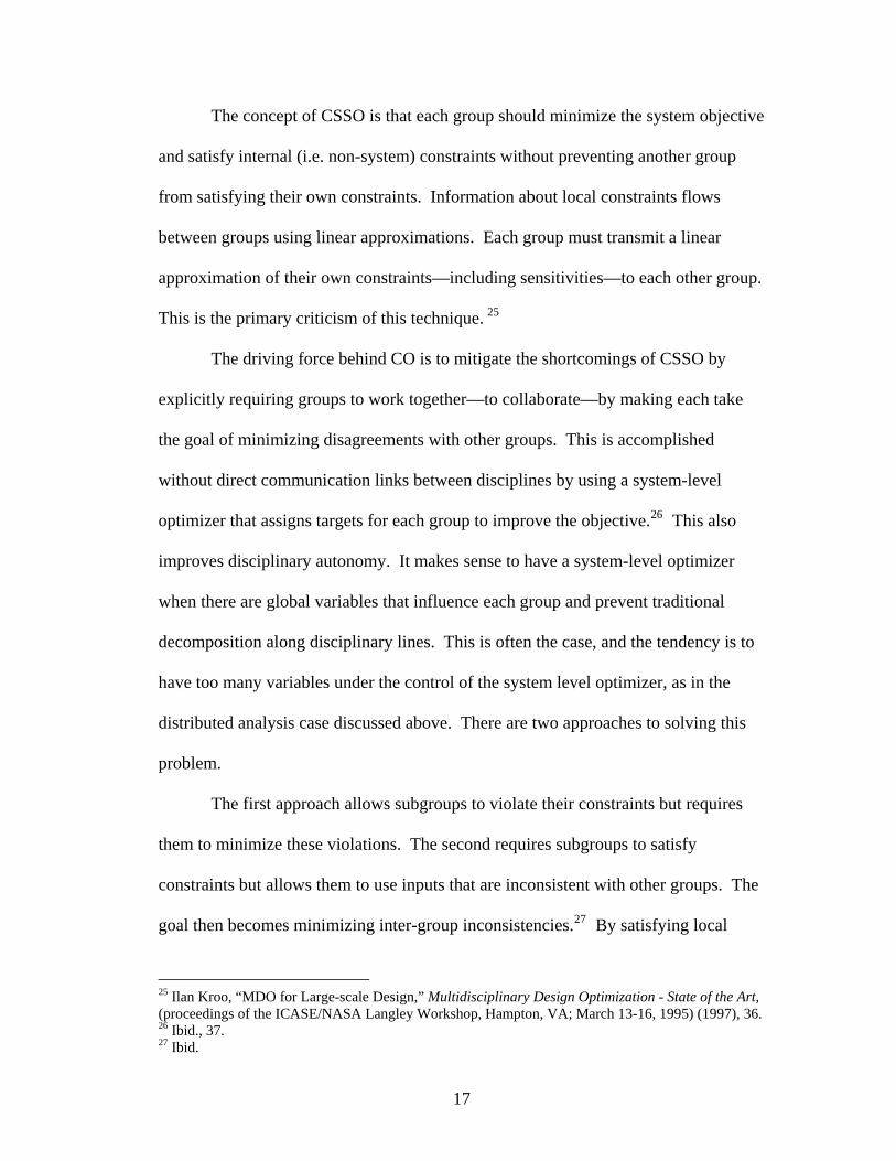
The concept of CSSO is that each group should minimize the system objec
and satisfy internal (i.e. non-system) constraints without preventing another group
from satisfying their own constraints. Information about local constraints flows
between groups using linear approximations. Each group must transmit a line
approximation of their own constraints—including sensitivities—to each other group.
This is the primary criticism of this technique.
tive
ar
nce each group and prevent traditional
decomp
ing this
25
The driving force behind CO is to mitigate the shortcomings of CSSO by
explicitly requiring groups to work together—to collaborate—by making each take
the goal of minimizing disagreements with other groups. This is accomplished
without direct communication links between disciplines by using a system-level
optimizer that assigns targets for each group to improve the objective.26 This also
improves disciplinary autonomy. It makes sense to have a system-level optimizer
when there are global variables that influe
osition along disciplinary lines. This is often the case, and the tendency is to
have too many variables under the control of the system level optimizer, as in the
distributed analysis case discussed above. There are two approaches to solv
problem.
The first approach allows subgroups to violate their constraints but requires
them to minimize these violations. The second requires subgroups to satisfy
constraints but allows them to use inputs that are inconsistent with other groups. The
goal then becomes minimizing inter-group inconsistencies.27 By satisfying local
25 Ilan Kroo, “MDO for Large-scale Design,” Multidisciplinary Design Optimization - State of the Art, (proceedings of the ICASE/NASA Langley Workshop, Hampton, VA; March 13-16, 1995) (1997), 36. 26 Ibid., 37. 27 Ibid.
17

constraints, transmission of discipline-specific information to other groups is
unnecessary. A subspace optimizer satisfies local constraints and minimizes
discrepancies between disciplines. The system level optimizer drives eliminates these
discrep
tive,
and recursive. It parallels the spiral design model—all of the steps from the
framework are applied at each stage of the SDLC. The process begins with
tradespace exploration to bound the problem and determine a range of potential
solutions. Then it goes immediately to modeling. Much of the discussion to this
point has been about the various organizational and scientific techniques for dividing
ancies by providing target values for shared parameters.
A framework for the generalized MSDO process adapted from MIT course
materials is shown in Figure 5, below. Notice that the process is sequential, itera
Figure 5: The MSDO Framework (de Weck and Wilcox, MSDO Lecture Notes, Session 2, 23)
responsibilities between disciplines within the simulation model block of Figure 5.
18
Once a preliminary solution is achieved, the model is tested using various
optimization algorithms and other special techniques. Then the process begins aga
perhaps with a more focused exploration of the design space using design of
experiment techniques.
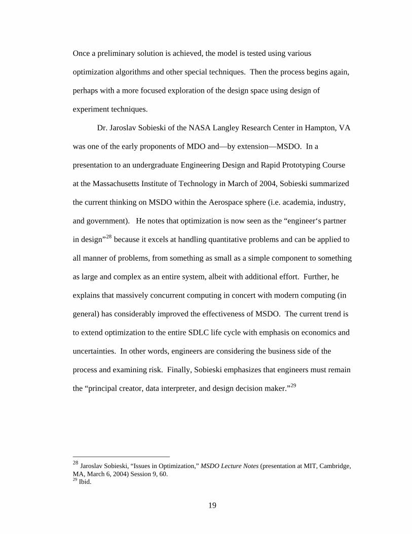
Dr. Jaroslav Sobieski of the NASA Langley Research Center in Hampton, VA
was one of the early proponents of MDO and—by extension—MS
in,
DO. In a
present
the current thinking on MSDO within the Aerospace sphere (i.e. academia, industry,
and government). He notes that optimization is now seen as the “engineer‘s partner
in design”28 because it excels at handling quantitative problems and can be applied to
all manner of problems, from something as small as a simple component to something
as large and complex as an entire system, albeit with additional effort. Further, he
explains that massively concurrent computing in concert with modern computing (in
general) has considerably improved the effectiveness of MSDO. The current trend is
to extend optimization to the entire SDLC life cycle with emphasis on economics and
uncertainties. In other words, engineers are considering the business side of the
process and examining risk. Finally, Sobieski emphasizes that engineers must remain
the “principal creator, data interpreter, and design decision maker.”29
ation to an undergraduate Engineering Design and Rapid Prototyping Course
at the Massachusetts Institute of Technology in March of 2004, Sobieski summarized
28 Jaroslav Sobieski, “Issues in Optimization,” MSDO Lecture Notes (presentation at MIT, Cambridge, MA, March 6, 2004) Session 9, 60. 29 Ibid.
19

Multidisciplinary design is typically associated with the traditional
engineering disciplines and specialties. Within the aerospace context, those might
include aerodynamics, propulsion, structures, and controls. But there are other
lifecycle areas to consider, including manufacturability, supportability, and
Design for value is another approach to MSDO that recognizes these concerns, as
depicted in Figure 6.
cost.30
The design for value model brings an economic perspective to MSDO.
Unfortunately, “value” is difficult to define because it depends heavily on the
application and stakeholders involved. Numerous financial metrics are available for
measuring value, each with attendant shortcomings. Net present value, payback
period and return on investment are some possible metrics, but each clarifies some
aspects of the value proposition while obscuring others. Finally, the inputs to these
Figure 6: Design for Value Approach MSDO Lecture Notes(de Weck and Wilcox, , Session 24, 37)
30 de Weck and Wilcox, MSDO Lecture Notes, Session 16, 6.
20
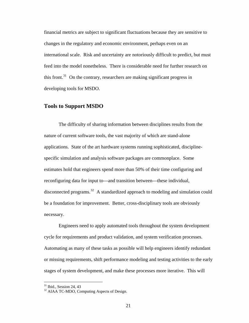
financial metrics are subject to significant fluctuations because they are sensitive to
changes in the regulatory and economic environment, perhaps even on an
international scale. Risk and uncertainty are notoriously difficult to predict, but must
feed into the model nonetheless. There is considerable need for further research on
this front.31 On the contrary, researchers are making significant progress in
developing tools for MSDO.
Tools to Support MSDO
The difficulty of sharing information between disciplines results from the
nature of current software tools, the vast majority of which are stand-alone
applications. State of the art hardware systems running sophisticated, discipline-
specific simulation and analysis software packages are commonplace. Some
estimates hold that engineers spend more than 50% of their time configuring and
reconfiguring data for input to—and transition between—these individual,
disconnected programs.32 A standardized approach to modeling and simulation could
be a foundation for improvement. Better, cross-disciplinary tools are obviously
necessary.
Engineers need to apply automated tools throughout the system development
cycle for requirements and product validation, and system verification processes.
Automating as many of these tasks as possible will help engineers identify redundant
or missing requirements, shift performance modeling and testing activities to the early
stages of system development, and make these processes more iterative. This will
31 Ibid., Session 24, 43
TC-MDO, Computing Aspects of Design. 32 AIAA
21
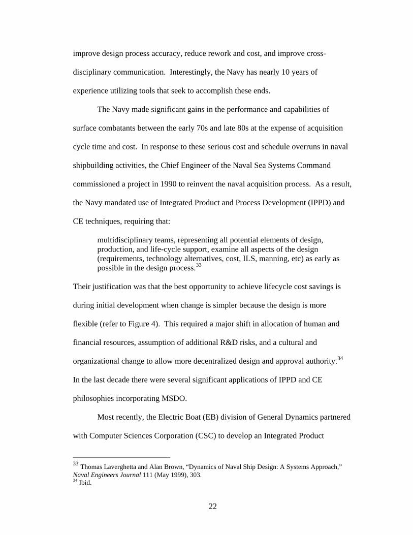
improv ss-
n response to these serious cost and schedule overruns in naval
shipbuilding activities, the Chief Engineer of the Naval Sea Systems Command
commissioned a project in 1990 to reinvent the naval acquisition process. As a result,
the Navy mandated use of Integrated Product and Process Development (IPPD) and
CE techniques, requiring that:
multidisciplinary teams, representing all potential elements of design, production, and life-cycle support, examine all aspects of the design (requirements, technology alternatives, cost, ILS, manning, etc) as early as possible in the design process.33
Their justification was that the best opportunity to achieve lifecycle cost savings is
during initial development when change is simpler because the design is more
flexible (refer to Figure 4). This required a major shift in allocation of human and
financial resources, assumption of additional R&D risks, and a cultural and
organiz .34
ered
e design process accuracy, reduce rework and cost, and improve cro
disciplinary communication. Interestingly, the Navy has nearly 10 years of
experience utilizing tools that seek to accomplish these ends.
The Navy made significant gains in the performance and capabilities of
surface combatants between the early 70s and late 80s at the expense of acquisition
cycle time and cost. I
ational change to allow more decentralized design and approval authority
In the last decade there were several significant applications of IPPD and CE
philosophies incorporating MSDO.
Most recently, the Electric Boat (EB) division of General Dynamics partn
with Computer Sciences Corporation (CSC) to develop an Integrated Product
33 Thomas Laverghetta and Alan Brown, “Dynamics of Naval Ship Design: A Systems Approach,” Naval Engineers Journal 111 (May 1999), 303. 34 Ibid.
22

Development Environment (IPDE) for the design and construction of the Navy’s
newest class of submarines, the USS Virginia. To achieve this end, EB ch
apply a CE approach within the framework of an IPDE, which provided the system
architecture needed to integrate the necessary engineering and business processes.
But first, EB had to re-engineer and redefine their processes and organization
align with CE principles. Wisely, EB chose
ose to
s to
to fully integrate their new, fully-digital
design and engineering environment with pre-existing construction systems to
revolutionize their entire system development processes (instead of just the front
end). T
ss”
art
gle
k-
”35
its systems engineering and architecture tools are useful in other
industr
he team achieved impressive results.
USS Virginia marked the first submarine ever designed in a “paperle
environment. The project achieved a 35% reduction in the design cycle time, in p
by maintaining a configuration controlled 3D virtual submarine design in a sin
digital database shared by all teams. They made extensive use of “electronic moc
ups” to virtually eliminate costly and time consuming physical mock-ups.
CSC claims their “IPDE is a revolutionary expansion of traditional CAD/CAM
interfaces resulting in a world class solution for digital design and manufacturing
and stresses
ies.
EB’s system allowed stakeholders from all phases of the system lifecycle—
shipbuilders, operators, engineers (doubtless from various domains of expertise),
designers and even vendors—to influence the ultimate design. The team achieved
important synergies by integrating construction and manufacturing perspectives into
orporation, “CSC Works With General Dynamics to Build Digital Design
defense/casestudies/1266.shtml>35 Computer Sciences CSolution” <http://www.csc.com/industries/aerospace
23

the design process. Notably, they matched the design to construction processe
facilities which enabled a smoother transition to production and reduced the
of changes late in the SDLC.
s and
number
ccess using IPPD in
the soft
Challenges
ry.
ntage of simplifications, but often requires high rate
2.
ow, bringing increased computation time.
lowing
e
2.
rike a balance between quantitative and qualitative methods and “allow for or
36 There are other examples of su
ware industry.
MSDO faces several challenges moving into the first decade of the 21st centu
Kroo predicted several issues facing MDO in the late 90s.37 MSDO must adapt to the
same challenges:
1. Optimization takes advafidelity disciplinary models to capture complex effects and ensure accuresults.
As models become more detailed and systems more complex, the degrees offreedom and dimensionality gr
3. Communication between team members in different locations is increasingly
difficult as teams and systems grow in size and complexity. 4. Many optimization algorithms themselves are poorly documented or ill suited
for various scenarios. Wilcox and de Weck further explore the challenges of MSDO, listing the fol
concerns,38 some of which parallel Kroo’s discussion:
1. Designers must balance size and fidelity to develop workable, error fremodels.
Engineers need tools to reduce the amount of time spent transferring data between applications (estimated at 50-80%).
3. Despite assertions to the contrary by some engineers, designers must st
gn—Status and Directions,” 3-4. ck and Wilcox, MSDO Lecture Notes, Session 25, 19.
36 Ibid. 37 Kroo, “MDO Applications in Preliminary Desi38 de We
24

creativity, intuition and ‘beauty,’ while leveraging rigorous, quantitative to39
dimensions a challenge.
5. There are many high level system architecture aspects conspicuously absent
environmental sustainability,”
ols in the design process.”
4. The limits of human perception make data visualization in multiple
from early design, including: “staged deployment, safety and security, [and]
s of
40 to name a few.
MSDO faces many of the same challenges that Systems Engineering faces.
Continued research and effort will doubtless improve the field, as will awarenes
these issues and discussion amongst engineering disciplines.
39 Ibid. 40 Ibid.
25

4. Conclusion
chnique. Derived from the Multidisciplinary Design
chniques of the aerospace industry and benefiting from decades of
experience and evolution, its purpose is to achieve an “optimal” design in a more
gen
em lifecycle—and as systems grow larger, more complicated and
inte
adaptation increasingly requires the input of diverse teams of experts in far flung
loca n
lifecycle perspective to concurren
man fa stems in demand
tod
Multidisciplinary System Design Optimization is a relatively new name and
application for a time tested te
Optimization te
eral sense.
As the concept of an optimal design continues to evolve to capture additional
aspects of the syst
rrelated—the processes for finding optimal designs will also evolve. This
tio s and utilizes the latest technologies. As such, applying a broad system
t, multi-disciplinary, computer aided design and
cturing is increasingly necessary in achieving the balanced syu
ay. MSDO stands poised to continue this ongoing revolution in systems
engineering.
26

Biblio
Alexandrov, Natalia M. and Robert Michael Lewis. “Analytical and Computational
oyne,
ishing
Application in Vehicle
Kroo, Ilan. “Multidisciplinary Optimization Applications in Preliminary Design—
Status and Directions.” Paper presented at the AIAA/ASME/ASCE/AHS/ASC Structures, Structural Dynamics, and Materials Conference and Exhibit, and the AIAA/ASME/AHS Adaptive Structures Forum, Kissimmee, Florida, April 7-10 1997.
Kroo, Ilan and Valerie Manning. “Collaborative Optimization: Status and
Directions.” Paper presented at the AIAA/NASA/ISSMO Symposium on Multidisciplinary Analysis and Optimization, Long Beach, California, September 6-8 2000.
Laverghetta, Tom and Alan Brown. “Dynamics of Naval Ship Design: A Systems
Approach.” Naval Engineers Journal 111 (1999): 307-324. Madni, Azad M., Carla Madni, an Weiwen Lin. “IDEON/IPPD: an Ontology for
Systems Engineering Process Design and Management.” IEEE (1998): 2597-2602.
Matthews, Clifford. Case Studies in Engineering Design. New York: John Wiley &
Sons Inc., 1998. Sydenham, Peter H. Systems Approach to Engineering Design. Norwood, MA:
Artech House, Inc., 2004.
graphy
Aspects of Collaborative Optimization for Multidisciplinary Design.” AIAA Journal 40 (2002): 301-309.
R. D., M. A. Rosenman, A. D. Radford, M. Balachandran, and J. S. Gero. CKnowledge-Based Design Systems. New York: Addison-Wesley PublCompany, 1990.
Kodiyalam, S. J. Sobieszcanski-Sobieski. “Multidisciplinary Design Optimization –
Some Formal Methods, Framework Requirements, andDesign.” Int. J. Vehicle Design Special Issue (2001): 3-22.
27


