

KUTAI ELECTRONICS INDUSTRY CO., LTD.
TEL : +886-7-8121771 FAX : +886-7-8121775 Website : www.kutai.com.tw
Headquarters : No.3, Lane 201, Chien Fu St., Chyan Jenn Dist., Kaohsiung 80664, TAIWAN
IVT-1260 & IVT-2460
Generator Auxiliary Excitation Booster Operation Manual
(Patent Pending)
The IVT-1260 / IVT-2460 is used to boost motor starting capacity in shunt generators. It achieves boosting power by converting DC battery power to an AC source for use by the AVR. It boosts the motor capacity of shunt generators like a PMG, augmenting the generator’s ability to handle a larger motor starting current, thereby exceeding its normal motor starting capabilities. It is easy to install, allowing the unit to be integrated to the generator excitation systems quickly.
Applicable for generator no-load excitation voltage between 20 50 Vdc. Suitable for full wave AVR equipped with Auxiliary power input.
Applicable AVR Models (More models adding continuously):
KUTAI EA08A, EA448, ADVR-12, ADVR-2200M Basler AVC63-12, AVC125-10, CATERPILLAR VR6

___________________________________________________________________________________________
2 IVT-1260 & IVT-2460
SECTION 1 : SPECIFICATION
Sensing Input (S1, S2) Static Power Dissipation
Voltage 80 600 Vac, 1 phase Less than 1 watt (hibernate Less than 0.5 watts)
Frequency 50/60 Hz
Efficiency
Power Output (OUT1, OUT2) greater than 90% @ Full load
Voltage 180 Vac, 1 phase
Max. Output 500VA Environment
Frequency 400/480 Hz Operation Temperature -40 to +70 ˚C
Storage Temperature -40 to +85 ˚C
Battery Power (Input B+, B-) Relative Humidity Max. 95%
Voltage IVT-1260 12 Vdc (8 18 Vdc) / 60A Vibration 3 Gs @ 100 2K Hz
IVT-2460 24 Vdc (16 36 Vdc) / 30A
Protections Battery Voltage Reverse Polarity Dimensions
Battery Current Limit 115.0 (L) x 115.0 (W) x 98.5 (H) mm
Fuse Spec. IVT-1260 (60A) / IVT-2460 (30A)
Weight
Typical System Response 2400 g +/- 2%
10 ms
SECTION 2 : OUTLINE / SIZE
Accessories : 1. Connection wires ( White x 2, Brown x 2 ) 2. Screw bolt M6L20 x 4
___________________________________________________________________________________________
IVT-1260 & IVT-2460 3
SECTION 3 : DESCRIPTION
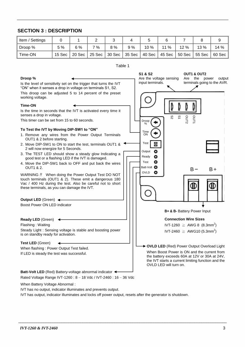
Item / Settings 0 1 2 3 4 5 6 7 8 9
Droop % 5 % 6 % 7 % 8 % 9 % 10 % 11 % 12 % 13 % 14 %
Time-ON 15 Sec 20 Sec 25 Sec 30 Sec 35 Sec 40 Sec 45 Sec 50 Sec 55 Sec 60 Sec
Table 1
Droop %
Is the level of sensitivity set on the trigger that turns the IVT “ON” when it senses a drop in voltage on terminals S1, S2.
This droop can be adjusted 5 to 14 percent of the preset working voltage.
Time-ON
Is the time in seconds that the IVT is activated every time it senses a drop in voltage.
This timer can be set from 15 to 60 seconds.
To Test the IVT by Moving DIP-SW1 to “ON”
1. Remove any wires from the Power Output Terminals OUT1 & 2 before starting.
2. Move DIP-SW1 to ON to start the test, terminals OUT1 & 2 will now energize for 5 Seconds.
3. The TEST LED should show a steady glow Indicating a good test or a flashing LED if the IVT is damaged.
4. Move the DIP-SW1 back to OFF and put back the wires OUT1 & 2.
WARNING !! When doing the Power Output Test DO NOT
touch terminals (OUT1 & 2). These emit a dangerous 180 Vac / 400 Hz during the test. Also be careful not to short these terminals, as you can damage the IVT.
Output LED (Green)
Boost Power ON LED indicator
Ready LED (Green)
Flashing : Waiting
Steady Light : Sensing voltage is stable and boosting power is on standby ready for activation.
Test LED (Green)
When flashing : Power Output Test failed.
If LED is steady the test was successful.
Batt-Volt LED (Red) Battery-voltage abnormal indicator Rated Voltage Range IVT-1260 : 8 18 Vdc / IVT-2460 : 16 36 Vdc
When Battery Voltage Abnormal :
IVT has no output, indicator illuminates and prevents output.
IVT has output, indicator illuminates and locks off power output, resets after the generator is shutdown.
OVLD LED (Red) Power Output Overload Light
When Boost Power is ON and the current from the battery exceeds 60A at 12V or 30A at 24V, the IVT starts a current limiting function and the OVLD LED will turn on.
Connection Wire Sizes
IVT-1260 ≧ AWG 8 (8.3mm2)
IVT-2460 ≧ AWG10 (5.3mm2)
B+ & B- Battery Power Input
S2
S1
OU
T2
OU
T1
B +B
Time
Test
Output
Ready
Test
Batt-Volt
OVLD
ON
Droop%
S1 & S2
Are the voltage sensing input terminals.
OUT1 & OUT2
Are the power output terminals going to the AVR.
___________________________________________________________________________________________
4 IVT-1260 & IVT-2460
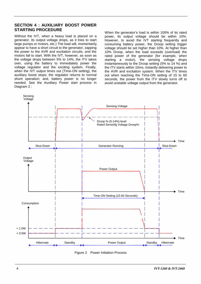
SECTION 4 : AUXILIARY BOOST POWER STARTING PROCEDURE
Without the IVT, when a heavy load is placed on a generator, its output voltage drops, as it tries to start large pumps or motors, etc.) The load will, momentarily, appear to have a short circuit to the generator, zapping the power to the AVR and excitation circuits, and the motors fail to start. With the IVT, however, as soon as the voltage drops between 5% to 14%, the ITV takes over, using the battery to immediately power the voltage regulator and the exciting system. Finally, when the IVT output times out (Time-ON setting), the auxiliary boost stops; the regulator returns to normal shunt operation; and, battery power is no longer needed. See the Auxiliary Power start process in Diagram 2 :
When the generator’s load is within 100% of its rated power, its output voltage should be within 10%. However, to avoid the IVT starting frequently and consuming battery power, the Droop setting trigger voltage should be set higher than 10%. At higher than 10% Droop, when the load exceeds (overload) the rated power of the generator (for example, when starting a motor), the sensing voltage drops instantaneously to the Droop setting (5% to 14 %) and the ITV starts within 10ms, instantly delivering power to the AVR and excitation system. When the ITV times out when reaching the Time-ON setting of 15 to 60 seconds, the power from the ITV slowly turns off to avoid unstable voltage output from the generator.
Time
Time
Hibernate Standby Power Output Standby
SensingVoltage
Consumption
Sensing Voltage
Droop % (5-14%) levelRated Sensinfg Voltage Droop%
Power Output
Time-ON Setting (15-60 Seconds)
Time
< 1.0W
< 0.5W
Shut-Down Generator Running Shut-Down
Hibernate
OutputVoltage
Figure 2 Power Initiation Process
___________________________________________________________________________________________
IVT-1260 & IVT-2460 5
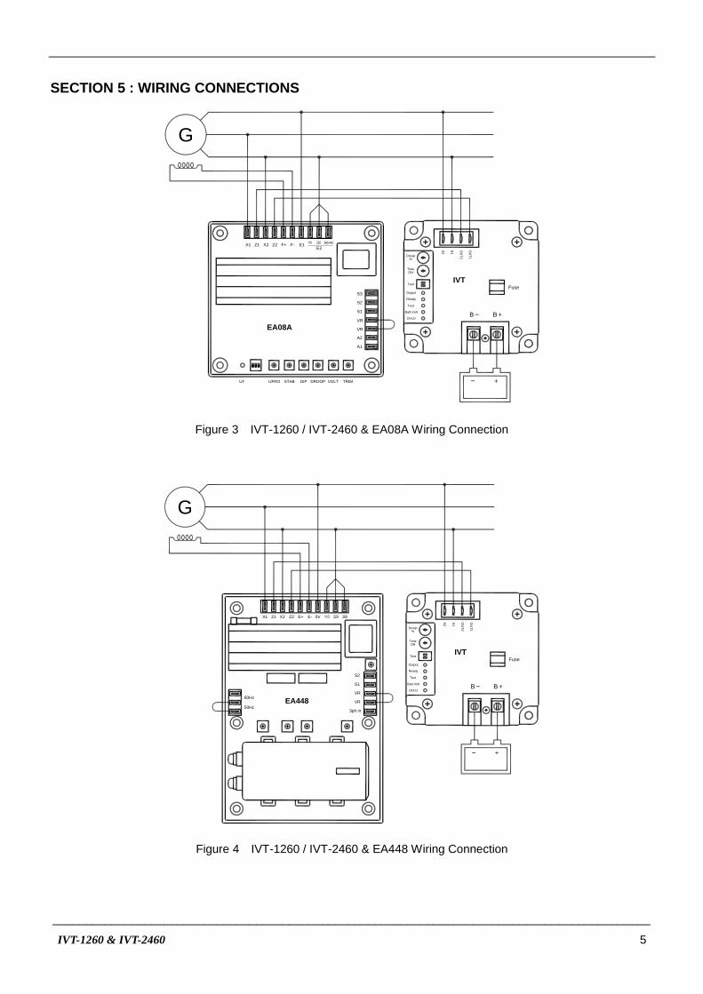
SECTION 5 : WIRING CONNECTIONS
G
+
S2
S1
OU
T2
OU
T1
B +B
Fuse
A2
A1
S1
VR
VR
S2
S3
UF UFRO DIPSTAB DROOP TRIM
Z2 F-F+X1 X2Z1E2
E1
VOLT
EA08A
Time
Test
Output
Ready
Test
Batt-Volt
OVLD
ON
Droop%
IVT
Figure 3 IVT-1260 / IVT-2460 & EA08A Wiring Connection
G
+
S2
S1
OU
T2
OU
T1
B +B
Fuse
EA448
Z2 E-E+X1 X2Z1 0V
60Hz
50Hz
S2
S1
VR
VR
3ph in
Time
Test
Output
Ready
Test
Batt-Volt
OVLD
ON
Droop%
IVT
Figure 4 IVT-1260 / IVT-2460 & EA448 Wiring Connection

___________________________________________________________________________________________
6 IVT-1260 & IVT-2460
+
OU
T1
OU
T2
+
B B
IVT
S2
S1
Fuse
Time
Test
Output
Ready
Test
Batt-Volt
OVLD
ON
Droop%
Armature
Exciter field
C.T
N:5Aor1A
S2-S3 N:1AS1-S2 N:5A
ADVR-08
S
T
R
Stator windings
Figure 5 IVT-1260 / IVT-2460 & ADVR-08 Wiring Connection
+
S2
S1
OU
T2
OU
T1
B +B
Fuse
G
F+ 30 28F-
ADVR-12
222426 20
9 7 6a8 55a6 4 G3 2
Time
Test
Output
Ready
Test
Batt-Volt
OVLD
ON
Droop%
IVT
Figure 6 IVT-1260 / IVT-2460 & ADVR-12 Wiring Connection

___________________________________________________________________________________________
IVT-1260 & IVT-2460 7
+
OU
T1
OU
T2
+
B B
IVT
S2
S1
E2
S
R
N
T
CT.
Fuse
E1
Excite
r
Stator Wires
Generator
P1E3 P2 F+ F-
A2
A1
VR2
VR1
Set the DIP SW Correctly
P4
P3
C2
C1
Shunt with IVT wiring diagram
Time
Test
Output
Ready
Test
Batt-Volt
OVLD
ON
Droop%
ADVR-2200M
ON ON
Figure 7 IVT-1260 / IVT-2460 & ADVR-2200M Wiring Connection
ATTENTION
1. All AC voltage readings are average value only.
2. IVT-1260 / IVT-2460 highest auxiliary output power is 500 VA.
3. IVT-1260 / IVT-2460 can combine with an auxiliary power AVR.
※ Use only the replacement fuses specified in this user manual.
※ Appearance and specifications of products are subject to change for improvement without prior notice.


