

SELECTIVE HEAT SINTERING VERSUS LASER SINTERING: COMPARISON OF
DEPOSITION RATE, PROCESS ENERGY CONSUMPTION AND COST
PERFORMANCE
M. Baumers*, C. Tuck*, and R. Hague*
*3D Printing Research Group (3DPRG), Faculty of Engineering, University of Nottingham,
Nottingham, NG7 2RD, UK
Abstract
The Selective Heat Sintering (SHS) process has become available as a low cost
alternative to Laser Sintering (LS) for the additive deposition of polymer objects. While both
processes belong to the powder bed fusion variant of Additive Manufacturing (AM) technology,
their operating principles vary significantly: SHS employs a thermal print head to selectively
fuse material powder, whereas the LS approach utilizes a laser beam coupled with a
galvanometer. Based on a series of build experiments, this research compares these technology
variants along three dimensions of process efficiency: deposition rate (measured in cm³/h),
specific process energy consumption (MJ/kg) and specific cost ($/cm³). To ensure that both
platforms are assessed under the condition of efficient technology utilization, an automatic
build volume packing algorithm is employed to configure a subset of build experiments.
Beyond reporting absolute and relative process performance, this paper additionally
investigates how sensitive the compared processes are to a variation in the degree of capacity
utilization and discusses the application of different levels of indirect cost in models of low cost
AM.
Introduction
As defined by the ASTM (2012), the term Additive Manufacturing (AM) describes a
group of technologies capable of combining materials to manufacture complex products in a
single process step. An important additional feature of the technology is that it permits the
deposition of multiple components in parallel (Ruffo et al., 2006) and does so without the need
for tooling of any kind (Hague et al., 2004). It has been noted that this one-step character lends
AM technology with an unprecedented level of transparency in terms of raw material and
energy consumption, and also cost (Baumers et al., 2013).
Above most other factors, the cost effectiveness of a new technology is a key
determinant of technology adoption decisions for commercial applications (see, for example,
Stoneman, 2002). To allow the ex-ante estimation of AM cost performance, a number of cost
estimators have been developed for various additive processes (Alexander et al., 1998;
Hopkinson and Dickens, 2003; Byun and Lee, 2006; Ruffo et al., 2006; Wilson, 2006; Munguia,
2009). As argued by Baumers et al. (2013), the assessment of AM cost and energy consumption
can be structured alongside each other. By studying both aspects in conjunction, it is possible
to implement a single methodology to make statements on both the private cost performance of
the technology as well the environmental impact.
A recent development in the AM industry is the emergence of low cost additive
platforms that aim to replicate the capability of more established processes, in the manufacture
of complex components. According to Gibson et al. (2010), the recent wave of low cost AM
109

systems is due to the expiry of the protection of key items of intellectual property and patents.
As part of an attempt an attempt to improve the understanding of the impact of this development
in the area of powder bed fusion technology, which carries great significance for the additive
manufacture of end-use products (Ruffo et al., 2006), this paper constructs an inter-process
comparison of machine productivity, process energy consumption and financial cost. In this
comparison, a Laser Sintering (LS) system is compared to the recently introduced Selective
Heat Sintering (SHS) process.
As shown Figure 1, the SHS process operates by selectively fusing a thin layer of
polymer powder via a thermal print head assembly. This assembly, which operates
bidirectionally, incorporates thermal printheads (a), powder deposition mechanisms (b), and
layer heaters (c). Material is built up in an internal build volume (d), the floor of which is a
vertically movable build platform (e). Fresh powder is supplied via scoops to the powder
deposition mechanism from powder containers (f). The print head assembly is separated from
the build surface by a thermally conductive sheet (g). This sheet is fed from a fresh sheet roll
(h) to a used sheet roll (i) during the process.
Figure 1: Schematic of the SHS process
Figure 2 shows a schematic diagram of LS. In LS, a laser system (a) is used to deflect a CO2
laser beam to selectively sinter powder material. Fresh powder is gravity fed from powder
containers (b) and infrared heating elements (c) are employed to preheat the build material.
Before each preheating and exposure process a powder wiper (d) spreads a fine layer of powder
over the build area (e), which is located over the vertically moveable build platform (f).
Additional build volume heating is performed by resistance heating elements (g); excess
unsintered material is discarded into overflow bins (h). Table 1 summarizes key characteristics
of the investigated SHS platform, the Blueprinter, and the LS system, an EOSINT P100.
110
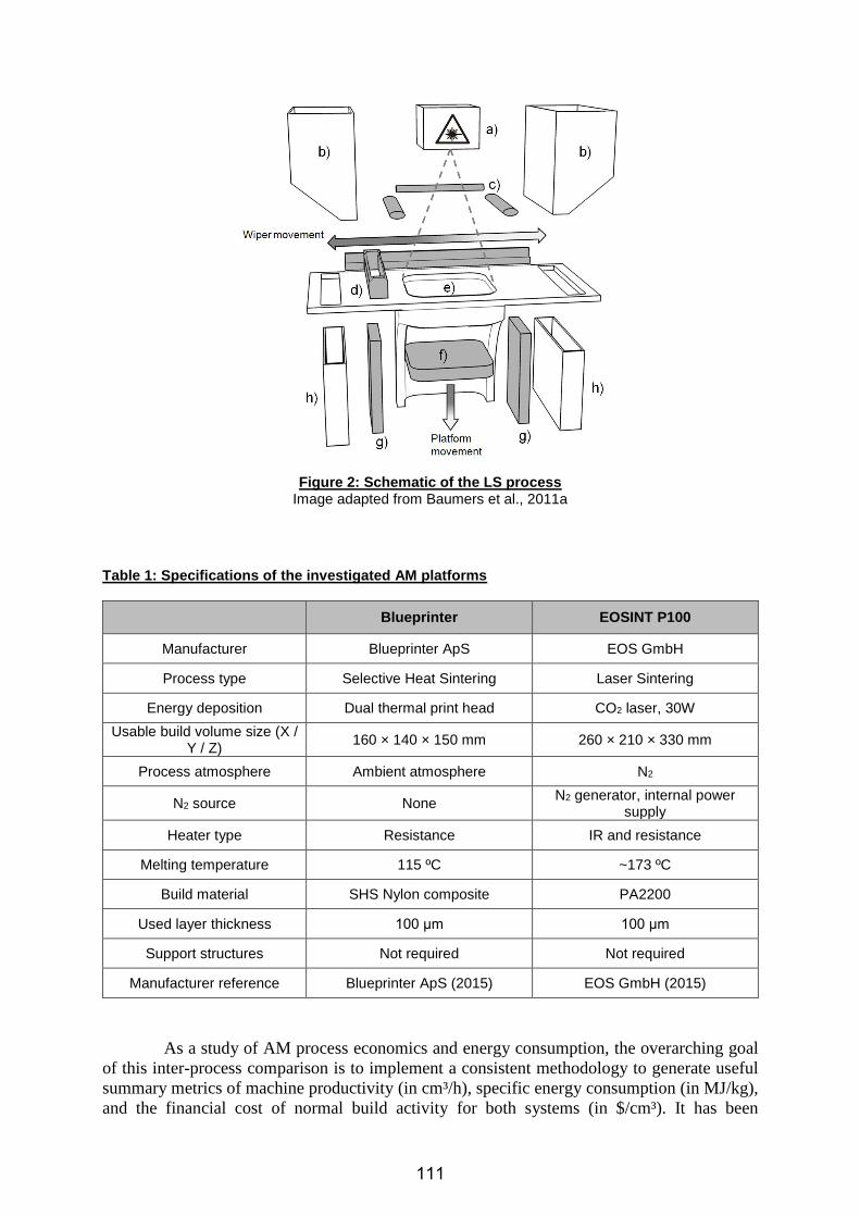
Figure 2: Schematic of the LS process Image adapted from Baumers et al., 2011a
Table 1: Specifications of the investigated AM platforms
Blueprinter EOSINT P100
Manufacturer Blueprinter ApS EOS GmbH
Process type Selective Heat Sintering Laser Sintering
Energy deposition Dual thermal print head CO2 laser, 30W
Usable build volume size (X / Y / Z)
160 × 140 × 150 mm 260 × 210 × 330 mm
Process atmosphere Ambient atmosphere N2
N2 source None N2 generator, internal power
supply
Heater type Resistance IR and resistance
Melting temperature 115 ºC ~173 ºC
Build material SHS Nylon composite PA2200
Used layer thickness 100 μm 100 μm
Support structures Not required Not required
Manufacturer reference Blueprinter ApS (2015) EOS GmbH (2015)
As a study of AM process economics and energy consumption, the overarching goal
of this inter-process comparison is to implement a consistent methodology to generate useful
summary metrics of machine productivity (in cm³/h), specific energy consumption (in MJ/kg),
and the financial cost of normal build activity for both systems (in $/cm³). It has been
111

demonstrated that powder bed fusion, in terms of energy consumption and cost, is sensitive to
variation in degrees of capacity utilization (Baumers et al., 2011b). To provide some clarity as
to whether SHS is sensitive to an underutilization of the available build capacity, as
demonstrated for LS, this research performs two build experiments on both platforms: an initial
single part build is performed to assess how well the platform performs if the available build
volume in not fully used up and a second experiment reflecting a fully occupied build volume.
As this paper forms a study of AM resource consumption, aspects relating to the mechanical
performance, integrity, surface quality, material characteristics, build failure and post
processing are omitted in this paper.
Methodology
The potential sensitivity of summary metrics of AM process performance to a variation
of the degree of capacity utilization, implies that a consistent methodology should be applied
to build experiments yielding such data. Thus, the experimental approach used in this paper is
to record the process performance for the competing AM processes in two specifically designed
build experiments:
- The initial build experiment performed on both systems analyses the deposition of
a single test specimen in the available build space. To limit deviation from efficient
technology operation, this geometry is located in the center of the available build
space in the X/Y plane and as close to the build platform as possible.
- The second build investigates the performance of the AM platform for full capacity
operation. Both SHS and LS allow the filling of the build volume via unconstrained
three dimensional placement of parts, resulting in three dimensional packing
configurations.
Due to AM platforms normally being single-machine electricity driven systems, the
measurement of energy inputs to individual build experiments is not complex. Process energy
consumption was recorded using a digital power meter (Yokogawa CW240) attached to the
multi-phase or single phase AC power supply. Energy consumption was monitored throughout
the entire build process, including any fixed process steps preceding and following the actual
build activity. These could be for example, bed heating or energy consumption during
machine’s cool down phase. In terms of the recorded electricity consumption data, the focus
lies on mean real power consumed per 1 second measurement cycle (measured in W) and the
total cumulative electric energy consumed (measured in Wh).
The implementation of power monitoring experiments with consistent packing
efficiency is based on a test part, as shown in Figure 3. Used in previous research, the ‘spider’
shape has been designed to have a relatively large footprint in the X/Y dimensions, thereby
limiting overall packing density and enabling fast and economical experiments.
112
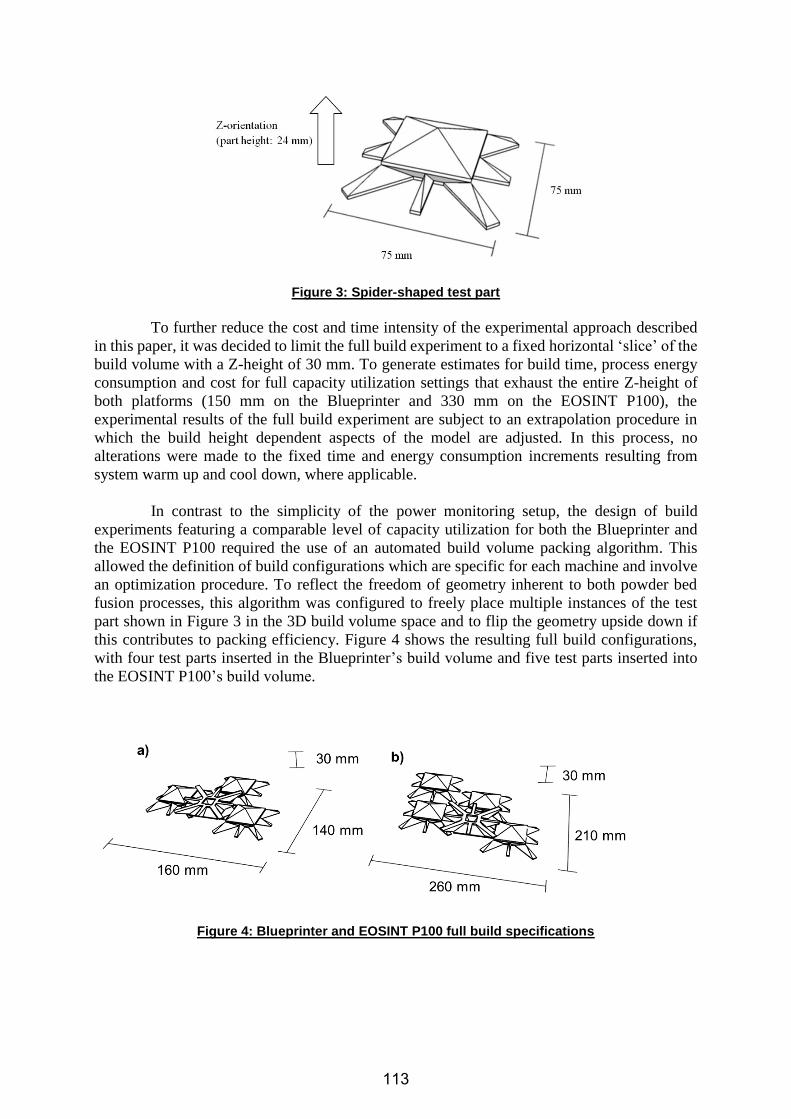
Figure 3: Spider-shaped test part
To further reduce the cost and time intensity of the experimental approach described
in this paper, it was decided to limit the full build experiment to a fixed horizontal ‘slice’ of the
build volume with a Z-height of 30 mm. To generate estimates for build time, process energy
consumption and cost for full capacity utilization settings that exhaust the entire Z-height of
both platforms (150 mm on the Blueprinter and 330 mm on the EOSINT P100), the
experimental results of the full build experiment are subject to an extrapolation procedure in
which the build height dependent aspects of the model are adjusted. In this process, no
alterations were made to the fixed time and energy consumption increments resulting from
system warm up and cool down, where applicable.
In contrast to the simplicity of the power monitoring setup, the design of build
experiments featuring a comparable level of capacity utilization for both the Blueprinter and
the EOSINT P100 required the use of an automated build volume packing algorithm. This
allowed the definition of build configurations which are specific for each machine and involve
an optimization procedure. To reflect the freedom of geometry inherent to both powder bed
fusion processes, this algorithm was configured to freely place multiple instances of the test
part shown in Figure 3 in the 3D build volume space and to flip the geometry upside down if
this contributes to packing efficiency. Figure 4 shows the resulting full build configurations,
with four test parts inserted in the Blueprinter’s build volume and five test parts inserted into
the EOSINT P100’s build volume.
Figure 4: Blueprinter and EOSINT P100 full build specifications
113

Results and Discussion
The research approach selected for this inter-process comparison aims to meet three
goals: firstly, it intends to present reliable experimental data on build time and process energy
consumption. Secondly, it aims to specify and compare summary metrics based on full capacity
utilization for machine productivity (deposition rate in cm³/h), process energy consumption
(specific energy consumption in MJ/kg) and cost estimates derived from an appropriate cost
model (specific cost in $/cm³). Thirdly, it aims to use these summary metrics of process
efficiency to compare differences in the sensitivity of both platforms to capacity
underutilization, which has been analyzed in financial terms (Ruffo et al., 2006) and for energy
inputs (Baumers et al., 2011b). It is important to note that this study ignores any technical
aspects relating to mechanical properties, material performance and deposition accuracy.
Additionally, the cost model proposed below ignores any ill-structured costs associated with
advanced manufacturing, such as those relating to build failure, error prevention, quality,
machine setup, waiting time, idleness and inventory (see, for example, Son, 1991).
The experimental results reached in this study are reported in Table 2. As can be seen,
both platforms required a considerable amount of time to complete each build experiment,
ranging from 581.60 min for the single part build on the EOSINT P100 to 887.77 min required
by the Blueprinter to complete the full build experiment, as shown above in Figure 4a. While
the EOSINT P100 required extensive warm up procedures, ranging from 149.93 min to 184.92
min, and operator determined cool down times, ranging from 300.00 min to 480.00 min, the
Blueprinter required only short system warm up times of 15.68 min for the single part build and
15.52 min for the full build, and no system cool down at all. At this point it is important to note
that both platforms allow the operator to remove the build volume, also referred to as powder
cake, after completion of the build for a rapid turnaround. This aspect is ignored in this study.
Due to the large amounts of unused machine capacity in both of the full build
experiments, the deposition rates measured in the experiments are not reflective of efficient
technology utilization and are therefore of little relevance for comparison to the literature. The
same applies to the observed specific energy consumption rate. However, the build energy
consumption rates, corresponding to mean real power consumption, observed on the EOSINT
P100 (1,395 W and 1,420 W) correspond well to matching measurements from the literature
(1,300 W, Kellens et al., 2010b). This indicates an accurate measurement setup.
114

Table 2: Experimental build time and power monitoring results
Blueprinter EOSINT P100
Single part Full build Single part Full build
Build time and
productivity
Total duration 659.00 min 887.77 min 581.60 min 833.64 min
Warm up 15.68 min 15.52 min 149.93 min 184.92 min
Deposition time 643.32 min 872.25 min 131.67 min 168.72 min
Cool down* N/A N/A 300.00 min 480.00 min
Deposition volume†
29.48 cm³ 117.92 cm³ 29.48 cm³ 147.40 cm³
Deposition rate 2.68 cm³/h 7.97 cm³/h 3.04 cm³/h 10.61 cm³/h
Energy consumption
Total energy consumption
15.14 MJ 20.71 MJ 33.41 MJ 42.44 MJ
Warm up energy
consumption 0.59 MJ 0.59 MJ 16.51 MJ 18.40 MJ
Deposition process energy
14.55 MJ 20.13 MJ 11.01 MJ 14.37 MJ
Cool down energy
N/A N/A 5.88 MJ 9.66 MJ
Deposition energy
consumption rate
377 J/s 385 J/s 1,395 J/s 1,420 J/s
Specific energy consumption†
466.88 MJ/kg 159.66 MJ/kg 1122.09 MJ/kg 285.07 MJ/kg
* Cool down duration based on operator discretion † Estimated, assuming density of 1.01 g/cm³ (PA2200) and 1.1 g/cm³ (SHS Nylon composite)
The next step in the analysis is the extrapolation of the experimental results obtained
in the full build experiments to the full Z-height of both machines. As described above, this is
done by keeping process elements relating to warm up and cool down (where applicable) fixed
and modifying the Z-height dependent process elements, which are net deposition time and
deposition energy consumption, to match the systems’ Z-height (150 mm on the Blueprinter
and 330 mm on the EOSINT P100). This resulted in the addition of four extra 30 mm Z-
increments containing an additional 16 parts on the Blueprinter and the addition of ten extra 30
mm Z-increments containing an additional 50 parts on the EOSINT P100. The extrapolated full
capacity model is therefor based on a total deposition volume of 589.60 cm³ on the Blueprinter
and a deposition volume of 1621.40 cm³ on the EOSINT P100. Table 3 reports results of the
extrapolated model.
115
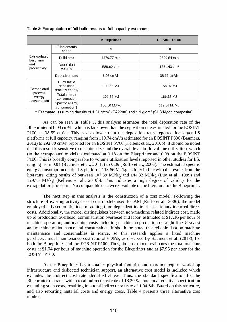
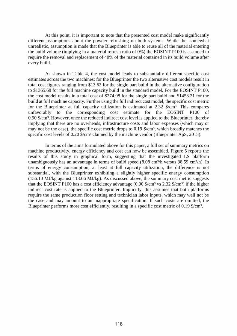
Table 3: Extrapolation of full build results to full capacity estimates
Blueprinter EOSINT P100
Extrapolated build time and productivity
Z-increments added
4 10
Build time 4376.77 min 2520.84 min
Deposition volume
589.60 cm³ 1621.40 cm³
Deposition rate 8.08 cm³/h 38.59 cm³/h
Extrapolated process energy
consumption
Cumulative deposition
process energy 100.65 MJ 158.07 MJ
Total energy consumption
101.24 MJ 186.13 MJ
Specific energy
consumption† 156.10 MJ/kg 113.66 MJ/kg
† Estimated, assuming density of 1.01 g/cm³ (PA2200) and 1.1 g/cm³ (SHS Nylon composite)
As can be seen in Table 3, this analysis estimates the total deposition rate of the
Blueprinter at 8.08 cm³/h, which is far slower than the deposition rate estimated for the EOSINT
P100, at 38.59 cm³/h. This is also lower than the deposition rates reported for larger LS
platforms at full capacity, ranging from 110.74 cm³/h estimated for an EOSINT P390 (Baumers,
2012) to 292.80 cm³/h reported for an EOSINT P760 (Kellens et al., 2010b). It should be noted
that this result is sensitive to machine size and the overall level build volume utilization, which
(in the extrapolated model) is estimated at 0.18 on the Blueprinter and 0.09 on the EOSINT
P100. This is broadly comparable to volume utilization levels reported in other studies for LS,
ranging from 0.04 (Baumers et al., 2011a) to 0.09 (Ruffo et al., 2006). The estimated specific
energy consumption on the LS platform, 113.66 MJ/kg, is fully in line with the results from the
literature, citing results of between 107.39 MJ/kg and 144.32 MJ/kg (Luo et al., 1999) and
129.73 MJ/kg (Kellens et al., 2010b). This indicates a high degree of validity for the
extrapolation procedure. No comparable data were available in the literature for the Blueprinter.
The next step in this analysis is the construction of a cost model. Following the
structure of existing activity-based cost models used for AM (Ruffo et al., 2006), the model
employed is based on the idea of adding time dependent indirect costs to any incurred direct
costs. Additionally, the model distinguishes between non-machine related indirect cost, made
up of production overhead, administration overhead and labor, estimated at $17.16 per hour of
machine operation, and machine costs including machine depreciation (straight line, 8 years)
and machine maintenance and consumables. It should be noted that reliable data on machine
maintenance and consumables is scarce, so this research applies a fixed machine
purchase/annual maintenance cost ratio of 6.05%, as observed by Baumers et al. (2013), for
both the Blueprinter and the EOSINT P100. Thus, the cost model estimates the total machine
costs at $1.04 per hour of machine operation for the Blueprinter and at $7.95 per hour for the
EOSINT P100.
As the Blueprinter has a smaller physical footprint and may not require workshop
infrastructure and dedicated technician support, an alternative cost model is included which
excludes the indirect cost rate identified above. Thus, the standard specification for the
Blueprinter operates with a total indirect cost rate of 18.20 $/h and an alternative specification
excluding such costs, resulting in a total indirect cost rate of 1.04 $/h. Based on this structure,
and also reporting material costs and energy costs, Table 4 presents three alternative cost
models.
116

Table 4: Cost model elements and comparison
Blueprinter
Blueprinter, alt. cost model
EOSINT P100
Data source
Single part Full build Single part
Full build Single part
Full build
Non-machine indirect cost
rate 17.16 $/h None 17.16 $/h
Adapted from Ruffo et al.,
2006
Machine purchase
$27995.00 $214469.90 Own data
Depreciation period
8 years Adapted from Ruffo et al.,
2006
Annual operating
time 5000 h
Adapted from Ruffo et al.,
2006 Estimated cost rate of
maintenance and
consumables*
0.34 $/h 2.60 $/h Own estimate
Total machine cost
rate† 1.04 $/h 7.95 $/h Own estimate
Total indirect cost rate
18.20 $/h 1.04 $/h 25.11 $/h Own estimate
Total indirect costs
$199.91 $1327.68 $11.42 $75.86 $243.50 $1055.39 Own estimate
Material refresh ratio
0% 40% Own estimate
Material consumption‡
0.03 kg 0.64 kg 0.03 kg 0.64 kg 0.42 kg 5.57 kg Based on a Z-height of 30.00mm
Raw material price
53.90 $/kg 70.42 $/kg Own data
Total material cost
$1.75 $34.96 $1.75 $34.96 $29.58 $392.24
Estimate based on net build volume size so likely
to be an underestimati
on
Energy price 0.03 $/MJ Own data
Energy costs $0.45 $3.04 $0.45 $3.04 $1.00 $5.58 Own estimate
Total cost $202.11 $1365.68 $13.62 $113.86 $274.08 $1453.21 Own estimate
Specific cost, per cm³
$6.86 $2.32 $0.46 $0.19 $9.30 $0.90 Own estimate
Specific cost, per part
$202.11 $68.28 $13.62 $5.69 $274.08 $26.42 Own estimate
* Based on a machine purchase/annual maintenance cost ratio of 6.05% adapted from Baumers et al. (2013) † Sum of cost rate of maintenance, consumables and depreciation costs
‡ Based on a density for unconsolidated powder of 0.6 (Ruffo et al., 2006), and the usable build volume sizes
listed in Table 1, assuming a cuboid build volume shape in both platforms
117
At this point, it is important to note that the presented cost model make significantly
different assumptions about the powder refreshing on both systems. While the, somewhat
unrealistic, assumption is made that the Blueprinter is able to reuse all of the material entering
the build volume (implying in a material refresh ratio of 0%) the EOSINT P100 is assumed to
require the removal and replacement of 40% of the material contained in its build volume after
every build.
As shown in Table 4, the cost model leads to substantially different specific cost
estimates across the two machines: for the Blueprinter the two alternative cost models result in
total cost figures ranging from $13.62 for the single part build in the alternative configuration
to $1365.68 for the full machine capacity build in the standard model. For the EOSINT P100,
the cost model results in a total cost of $274.08 for the single part build and $1453.21 for the
build at full machine capacity. Further using the full indirect cost model, the specific cost metric
for the Blueprinter at full capacity utilization is estimated at 2.32 $/cm³. This compares
unfavorably to the corresponding cost estimate for the EOSINT P100 of
0.90 $/cm³. However, once the reduced indirect cost level is applied to the Blueprinter, thereby
implying that there are no overheads, infrastructure costs and labor expenses (which may or
may not be the case), the specific cost metric drops to 0.19 $/cm³, which broadly matches the
specific cost levels of 0.20 $/cm³ claimed by the machine vendor (Blueprinter ApS, 2015).
In terms of the aims formulated above for this paper, a full set of summary metrics on
machine productivity, energy efficiency and cost can now be assembled. Figure 5 reports the
results of this study in graphical form, suggesting that the investigated LS platform
unambiguously has an advantage in terms of build speed (8.08 cm³/h versus 38.59 cm³/h). In
terms of energy consumption, at least at full capacity utilization, the difference is not
substantial, with the Blueprinter exhibiting a slightly higher specific energy consumption
(156.10 MJ/kg against 113.66 MJ/kg). As discussed above, the summary cost metric suggests
that the EOSINT P100 has a cost efficiency advantage (0.90 $/cm³ vs 2.32 $/cm³) if the higher
indirect cost rate is applied to the Blueprinter. Implicitly, this assumes that both platforms
require the same production floor setting and technician labor inputs, which may well not be
the case and may amount to an inappropriate specification. If such costs are omitted, the
Blueprinter performs more cost efficiently, resulting in a specific cost metric of 0.19 $/cm³.
118

Figure 5: Comparing summary metrics of the combined model
Unambiguously, this research demonstrates that both the SHS and LS are highly
sensitive to to the degree of machine capacity utilization, with all three types of metric
(productivity, process energy and cost) benefitting substantially from the exploitation of the
available Z-height and density of parts in the build volume, as discussed by Telenko and
Seepersad (2010).
Conclusions
After presenting the results of the experimental portion of this research into resource
consumption characteristics of the Blueprinter and the EOSINT P100, this paper has presented
a set of summary metrics of system productivity, process energy consumption and specific cost.
These metrics indicate that if an identical workshop setting and dedicated technician support is
assumed, the EOSINT P100 appears to be at an advantage. Additionally, it is demonstrated that
both platforms are sensitive to capacity underutilization. This highlights the requirement for
methodologies that fill the available build volume, for example via automated build volume
packing techniques.
Beyond this, the real insight gleaned in this research relates to cost model design. Low
cost platforms such as Makerbot, Formlabs and also the Blueprinter are not designed for the
production facility environment. Therefore cost models reflecting such an infrastructure (see,
for example, Ruffo et al., 2006), including dedicated labor inputs, may be inappropriate. As
observed in this research, the application of such a cost model, with high levels of indirect cost
in particular, leads to high specific cost levels (2.32 $/cm³) despite the Blueprinter being
marketed as a low cost AM system. For this reason, further research into methodologies
capturing the value proposition of low cost AM systems is urgently required.
119

Acknowledgments
The authors wish to acknowledge the support given by AM technician Joseph White
during the experimental phase of this research and the contributions made by summer intern
Jack Jones to error checking the presented model estimates.
References
1. Alexander, P., Allen, S., and Dutta, D., 1998. Part orientation and build cost determination in
layered manufacturing, Computer-Aided Design, 30 (5), pp. 343-356.
2. ASTM, 2012. “ASTM F2792 - 12e1 Standard Terminology for Additive Manufacturing
Technologies,” www.astm.org/Standards/F2792.htm.
3. Baumers, M., Tuck, C., Wildman, R., Ashcroft, I., Rosamond, R., and Hague, R., 2013.
Transparency built-in: energy consumption and cost estimation for Additive Manufacturing,
Journal of Industrial Ecology, 17(3) (2013) pp.418-431.
4. Baumers, M., 2012. Economic aspects of additive manufacturing: benefits, costs and energy
consumption. PhD thesis. Loughborough University.
5. Baumers M., Tuck, C., Bourell, D., Sreenivasan, R., Hague, R., 2011a. Sustainability of
additive manufacturing: measuring the energy consumption of the laser sintering process.
Proceedings of the Institution of Mechanical Engineers Part B: Journal of Engineering
Manufacture.225 (12), pp. 2228-2239.
6. Baumers, M., Tuck, C., Wildman, R., Ashcroft, I., and Hague, R., 2011b. Energy inputs to
additive manufacturing: does capacity utilization matter?, Proceedings of the Solid Freeform
Fabrication (SFF) Symposium 2011. The University of Texas at Austin.
7. Blueprinter ApS, 2015. [Corporate Website]. Available from: http://www.blueprinter.dk/
[Accessed: 01.07.2015].
8. Byun, H., Lee, K. H., 2006. Determination of the optimal build direction for different rapid
prototyping processes using multi-criterion decision making, Robotics and Computer-
Integrated Manufacturing, 22 (1), pp.69-80.
9. Munguia, F. J., 2009. RMADS: Development of a concurrent Rapid Manufacturing Advice
System, Ph.D. thesis, Universitat Politecnica de Catalunya, Barcelona, Spain.
10. EOS GmbH, 2015. [Corporate Website]. Available from: http://www.eos.info/ [Accessed:
01.07.2015].
11. Gibson, I., Rosen, D., W., Stucker, B., 2010, Additive Manufacturing Technology – Rapid
Prototyping to Direct Digital Manufacturing. Springer, New York.
12. Hague, R., Mansour, S., and Saleh, N., 2004. Material and design considerations for Rapid
Manufacturing. International Journal of Production Research, 42 (22), pp. 4691-4708.
13. Hopkinson, N., and Dickens, P., 2003. Analysis of rapid manufacturing -using layer
manufacturing processes for production. Proceedings of the Institution of Mechanical
Engineers, Part C: Journal of Mechanical Engineering Science. 217 (C1), pp. 31-39.
120

14. Kellens, K., Dewulf, W., Deprez, W., Yasa, E., and Duflou, J., 2010a. Environmental analysis
of SLM and SLS manufacturing processes. Proceedings of LCE2010 Conference. Hefei,
China, 19 - 21.05.2010, pp. 423 -428.
15. Kellens, K., Yasa, E., Dewulf, W., Duflou, J., 2010b. Environmental Assessment of Selective
Laser Melting and Selective Laser Sintering. Going Green – CARE INNOVATION 2010,
Vienna, Austria, 8 – 11.11.2010.
16. Luo, Y., Ji, Z., Leu, M. C., and Caudill, R., 1999. Environmental Performance Analysis of
Solid Freeform Fabrication Processes. Proceedings of the 1999 IEEE International
Symposium on Electronics and the Environment, pp 1-6.
17. Ruffo, M., Tuck, C., and Hague, R., 2006. Cost estimation for rapid manufacturing – laser
sintering production for low to medium volumes. Proceedings of IMech E Part B: Journal of
Engineering Manufacture, 220(9), pp.1417-1427.
18. Son, Y. K., 1991. A cost estimation model for advanced manufacturing systems. International
Journal of Production Research, 29(3), pp. 441-452.
19. Stoneman, P., 2002. The Economics of Technological Diffusion. Oxford: Blackwell.
20. Telenko, C., and Seepersad, C. C., 2010. Assessing Energy Requirements and Material Flows
of Selective Laser Sintering of Nylon Parts. Proceedings of the Solid Freeform Fabrication
Symposium 2010, Austin, USA, 8 – 10.08.2010, pp. 289-297.
21. Wilson, J. O., 2006. Selection for rapid manufacturing under epistemic uncertainty, Master’s
thesis. Georgia Institute of Technology, Atlanta, USA.
121


