
1
Ordering Information: Amplifier Units, Connectors and Accessories
Amplifier Units
Amplifier Units with Cables
Amplifier Units with Connectors
Amplifier Unit Connectors (Order Separately)Note Stickers for Connectors are included as accessories.
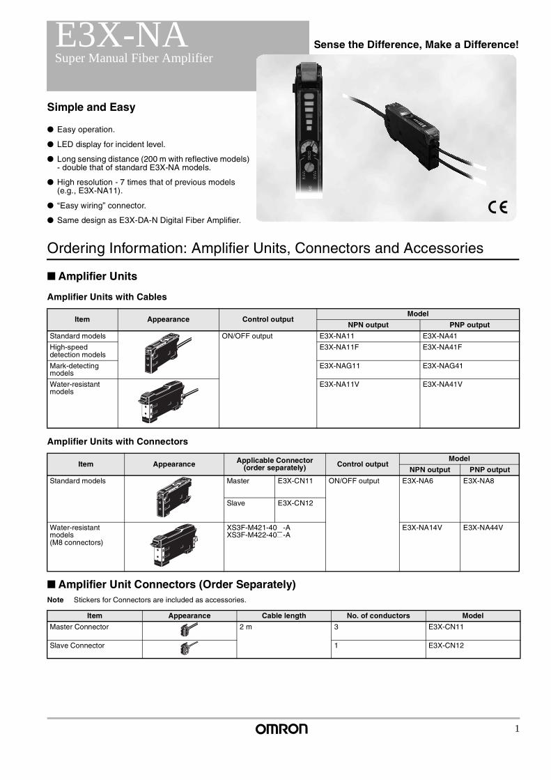
E3X-NA Sense the Difference, Make a Difference!Super Manual Fiber Amplifier
Simple and Easy
Easy operation.
LED display for incident level.
Long sensing distance (200 m with reflective models) - double that of standard E3X-NA models.
High resolution - 7 times that of previous models (e.g., E3X-NA11).
“Easy wiring” connector.
Same design as E3X-DA-N Digital Fiber Amplifier.
Item Appearance Control outputModel
NPN output PNP output
Standard models ON/OFF output E3X-NA11 E3X-NA41
High-speed detection models
E3X-NA11F E3X-NA41F
Mark-detecting models
E3X-NAG11 E3X-NAG41
Water-resistant models
E3X-NA11V E3X-NA41V
Item Appearance Applicable Connector (order separately) Control output
Model
NPN output PNP output
Standard models Master E3X-CN11 ON/OFF output E3X-NA6 E3X-NA8
Slave E3X-CN12
Water-resistant models(M8 connectors)
XS3F-M421-40@-AXS3F-M422-40@-A
E3X-NA14V E3X-NA44V
Item Appearance Cable length No. of conductors Model
Master Connector 2 m 3 E3X-CN11
Slave Connector 1 E3X-CN12
2
E3X-NA Super Manual Fiber Amplifier
Combining Amplifier Units and ConnectorsRefer to the following tables when placing an order. Basically, Amplifier Units and Connectors are sold separately.
Sensor I/O Connectors (Order Separately)
Accessories (Order Separately)
Mounting Brackets
End Plate
Size Cable specifications Appearance Cable type Model
M8 Standard cable Straight connector 2 m Four-core cable XS3F-M421-402-A
5 m XS3F-M421-405-A
L-shaped connector 2 m XS3F-M422-402-A
5 m XS3F-M422-405-A
Amplifier Units
Type NPN PNP
Standard models E3X-NA6 E3X-NA8 +
Applicable Connectors (Order Separately)
Master Connector Slave Connector
E3X-CN11 (3-wire) E3X-CN12 (1-wire)
Amplifier Units (5 Units) + 1 Master Connector + 4 Slave Connectors
When Using 5 Amplifier Units
Appearance Applicable models Model Quantity
E3X-NA@E3X-NA@FE3X-NAG@
E39-L143 1
E3X-NA@V E39-L148
Appearance Model Quantity
PFP-M 1
3
Super Manual Fiber Amplifier E3X-NA
Specifications: Amplifier Units
Ratings/Characteristics
Note When there are 8 or more Units mounted side-by-side, the response time will be 350 µs max.
Amplifier Unit Connectors
Item
Amplifier Units with Cables Amplifier Units with Connectors
Standard modelsHigh-speed detection models
Mark-detecting models
Water-resistant models
Standard models
Water-resistant models (M8 connectors)
Output typeNPN output E3X-NA11 E3X-NA11F E3X-NAG11 E3X-NA11V E3X-NA6 E3X-NA14V
PNP output E3X-NA41 E3X-NA41F E3X-NAG41 E3X-NA41V E3X-NA8 E3X-NA44V
Light source (wavelength) Red LED (680 nm) Green LED (520 nm)
Red LED (680 nm)
Supply voltage 12 to 24 VDC ±10%, ripple (p-p): 10% max.
Current consumption 35 mA max. 35 mA max.(for 24-VDC power supply)
35 mA max.
Control output NPN/PNP (depends on model) open collector; load current: 50 mA max.; residual voltage: 1 V max.; Light ON/Dark ON mode selector
Response time 200 µs max. for operation and reset respectively (See note.)
Operation: 20 µs max.Reset: 30 µs max.
200 µs max. for operation and reset respectively (See note.)
Sensitivity adjustment 8-turn sensitivity adjuster (with indicator)
Circuit protection Reverse polarity, output short-circuit, mutual inter-ference prevention (opti-cally synchronized)
Reverse polari-ty, output short-circuit
Reverse polarity, output short-circuit, mutual interference prevention (optically synchronized)
Timer function OFF-delay timer: 40 ms (fixed)
Ambient illumination(receiver side)
Incandescent lamp:10,000 lux max.Sunlight: 20,000 lux max.
Ambient temperature Operating: Groups of 1 to 3 Amplifiers: −25°C to 55°CGroups of 4 to11 Amplifiers: −25°C to 50°CGroups of 12 to16 Amplifiers: −25°C to 45°C (with no icing or condensation)
Storage: −30°C to 70°C (with no icing or condensation)
Ambient humidity Operating and storage: 35% to 85% (with no condensation)
Insulation resistance 20 MΩ min. (at 500 VDC)
Dielectric strength (destruction) 1,000 VAC at 50/60 Hz for 1 minute 500 VAC at 50/60 Hz for 1 minute
Vibration resistance (destruction)
10 to 55 Hz with a 1.5-mm double amplitude for 2 hrs each in X, Y and Z directions
Shock resistance (destruction) 500 m/s2, for 3 times each in X, Y and Z directions
Enclosure rating IEC60529 IP50 (with Protective Cover attached) IEC60529 IP66 (with Protective Cover attached)
IEC60529 IP50 (with Protective Cover attached)
IEC60529 IP66 (with Protective Cover at-tached)
Connection method Pre-wired (standard cable length: 2 m) Connector M8 connector
Weight (packed state) Approx. 100 g Approx. 110 g Approx. 55 g Approx. 65 g
Material Case Polybutylene terephthalate (PBT)
Cover Polycarbonate Polyethersulfone (PES)
Polycarbonate Polyethersulfone (PES)
Accessories Instruction Sheet
Item E3X-CN11 E3X-CN12
Rated current 2.5 A
Rated voltage 50 V
Contact resistance 20 mΩ max. (20 mVDC max., 100 mA max.)(The above figure is for connection to the Amplifier Unit and the adjacent Connector. It does not include the con-ductor resistance of the cable.)
Number of insertions (destruction)
50 times (for connection to the Amplifier Unit and the adjacent Connector)
Material Housing Polybutylene terephthalate (PBT)
Contact Phosphor bronze/gold-plated nickel
Weight (packed state) Approx. 55 g Approx. 25 g
4
E3X-NA Super Manual Fiber Amplifier
Ordering Information: Fiber Units
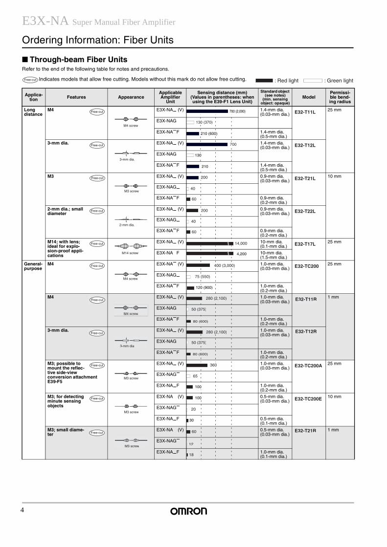
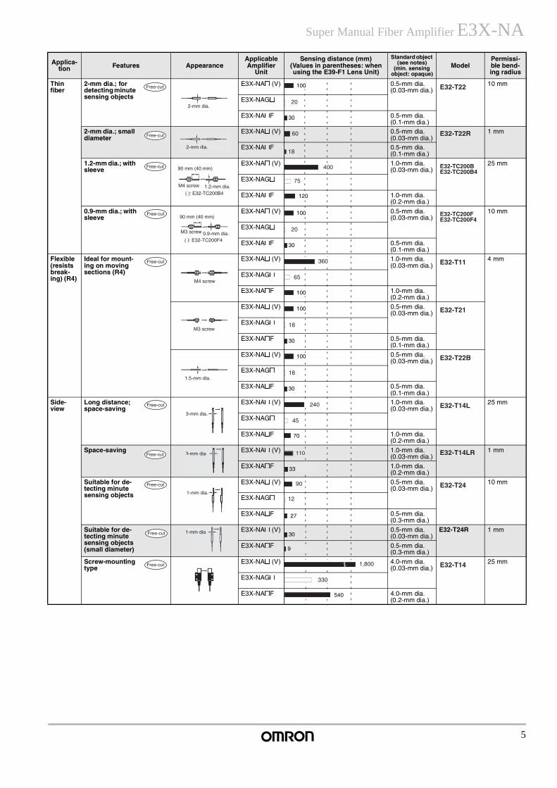
Through-beam Fiber UnitsRefer to the end of the following table for notes and precautions.
Indicates models that allow free cutting. Models without this mark do not allow free cutting.
Applica-tion Features Appearance
Applicable Amplifier
Unit
Sensing distance (mm)(Values in parentheses: when using the E39-F1 Lens Unit)
Standard object (see notes)
(min. sensing object: opaque)
ModelPermissi-ble bend-ing radius
Long distance
M4 E3X-NA@ (V) 1.4-mm dia.(0.03-mm dia.)
25 mm
E3X-NAG@
E3X-NA@F 1.4-mm dia.(0.5-mm dia.)
3-mm dia. E3X-NA@ (V) 1.4-mm dia.(0.03-mm dia.)
E3X-NAG@
E3X-NA@F 1.4-mm dia.(0.5-mm dia.)
M3 E3X-NA@ (V) 0.9-mm dia.(0.03-mm dia.)
10 mm
E3X-NAG@
E3X-NA@F 0.9-mm dia.(0.2-mm dia.)
2-mm dia.; small diameter
E3X-NA@ (V) 0.9-mm dia.(0.03-mm dia.)
E3X-NAG@
E3X-NA@F 0.9-mm dia.(0.2-mm dia.)
M14; with lens; ideal for explo-sion-proof appli-cations
E3X-NA@ (V) 10-mm dia.(0.1-mm dia.)
25 mm
E3X-NA@F 10-mm dia.(1.5-mm dia.)
General-purpose
M4 E3X-NA@ (V) 1.0-mm dia.(0.03-mm dia.)
25 mm
E3X-NAG@
E3X-NA@F 1.0-mm dia.(0.2-mm dia.)
M4 E3X-NA@ (V) 1.0-mm dia.(0.03-mm dia.)
1 mm
E3X-NAG@
E3X-NA@F 1.0-mm dia.(0.2-mm dia.)
3-mm dia. E3X-NA@ (V) 1.0-mm dia.(0.03-mm dia.)
E3X-NAG@
E3X-NA@F 1.0-mm dia.(0.2-mm dia.)
M3; possible to mount the reflec-tive side-view conversion attachment E39-F5
E3X-NA@ (V) 1.0-mm dia.(0.03-mm dia.)
25 mm
E3X-NAG@
E3X-NA@F 1.0-mm dia.(0.2-mm dia.)
M3; for detecting minute sensing objects
E3X-NA@ (V) 0.5-mm dia.(0.03-mm dia.)
10 mm
E3X-NAG@
E3X-NA@F 0.5-mm dia.(0.1-mm dia.)
M3; small diame-ter
E3X-NA@ (V) 0.5-mm dia.(0.03-mm dia.)
1 mm
E3X-NAG@
E3X-NA@F 1.0-mm dia.(0.1-mm dia.)
Free-cut : Red light : Green light
Free-cut
M4 screw
700 (2,000) E32-T11L
130 (370)
210 (600)
Free-cut
3-mm dia.
700 E32-T12L
130
210
Free-cut
M3 screw
200 E32-T21L
40
60
Free-cut
2-mm dia.
200 E32-T22L
40
60
Free-cut
M14 screw
14,000 E32-T17L
4,200
Free-cut
M4 screw
400 (3,000) E32-TC200
75 (550)
120 (900)
Free-cut
M4 screw
280 (2,100) E32-T11R
50 (375)
80 (600)
Free-cut
3-mm dia.
280 (2,100) E32-T12R
50 (375)
80 (600)
Free-cut
M3 screw
360 E32-TC200A
65
100
Free-cut
M3 screw
100 E32-TC200E
20
30
Free-cut
M3 screw
60 E32-T21R
12
18
5
Super Manual Fiber Amplifier E3X-NA
Thin fiber
2-mm dia.; for detecting minute sensing objects
E3X-NA@ (V) 0.5-mm dia.(0.03-mm dia.)
10 mm
E3X-NAG@
E3X-NA@F 0.5-mm dia.(0.1-mm dia.)
2-mm dia.; small diameter
E3X-NA@ (V) 0.5-mm dia.(0.03-mm dia.)
1 mm
E3X-NA@F 0.5-mm dia.(0.1-mm dia.)
1.2-mm dia.; with sleeve
E3X-NA@ (V) 1.0-mm dia.(0.03-mm dia.)
25 mm
E3X-NAG@
E3X-NA@F 1.0-mm dia.(0.2-mm dia.)
0.9-mm dia.; with sleeve
E3X-NA@ (V) 0.5-mm dia.(0.03-mm dia.)
10 mm
E3X-NAG@
E3X-NA@F 0.5-mm dia.(0.1-mm dia.)
Flexible (resists break-ing) (R4)
Ideal for mount-ing on moving sections (R4)
E3X-NA@ (V) 1.0-mm dia.(0.03-mm dia.)
4 mm
E3X-NAG@
E3X-NA@F 1.0-mm dia.(0.2-mm dia.)
E3X-NA@ (V) 0.5-mm dia.(0.03-mm dia.)
E3X-NAG@
E3X-NA@F 0.5-mm dia.(0.1-mm dia.)
E3X-NA@ (V) 0.5-mm dia.(0.03-mm dia.)
E3X-NAG@
E3X-NA@F 0.5-mm dia.(0.1-mm dia.)
Side-view
Long distance; space-saving
E3X-NA@ (V) 1.0-mm dia.(0.03-mm dia.)
25 mm
E3X-NAG@
E3X-NA@F 1.0-mm dia.(0.2-mm dia.)
Space-saving E3X-NA@ (V) 1.0-mm dia.(0.03-mm dia.)
1 mm
E3X-NA@F 1.0-mm dia.(0.2-mm dia.)
Suitable for de-tecting minute sensing objects
E3X-NA@ (V) 0.5-mm dia.(0.03-mm dia.)
10 mm
E3X-NAG@
E3X-NA@F 0.5-mm dia.(0.3-mm dia.)
Suitable for de-tecting minute sensing objects (small diameter)
E3X-NA@ (V) 0.5-mm dia.(0.03-mm dia.)
E32-T24R 1 mm
E3X-NA@F 0.5-mm dia.(0.3-mm dia.)
Screw-mounting type
E3X-NA@ (V) 4.0-mm dia.(0.03-mm dia.)
25 mm
E3X-NAG@
E3X-NA@F 4.0-mm dia.(0.2-mm dia.)
Applica-tion Features Appearance
Applicable Amplifier
Unit
Sensing distance (mm)(Values in parentheses: when using the E39-F1 Lens Unit)
Standard object (see notes)
(min. sensing object: opaque)
ModelPermissi-ble bend-ing radius
Free-cut
2-mm dia.
100 E32-T22
20
30
Free-cut
2-mm dia.
60 E32-T22R
18
Free-cut
M4 screw
90 mm (40 mm)
1.2-mm dia.( ): E32-TC200B4
400 E32-TC200BE32-TC200B4
75
120
Free-cut
M3 screw
90 mm (40 mm)
( ): E32-TC200F40.9-mm dia.
100 E32-TC200FE32-TC200F4
20
30
Free-cut
M4 screw
360 E32-T11
65
100
M3 screw
100 E32-T21
18
30
1.5-mm dia.
100 E32-T22B
18
30
Free-cut
3-mm dia.
240 E32-T14L
45
70
Free-cut 3-mm dia. 110 E32-T14LR
33
Free-cut
1-mm dia.
90 E32-T24
12
27
Free-cut 1-mm dia. 30
9
Free-cut 1,800 E32-T14
330
540
6
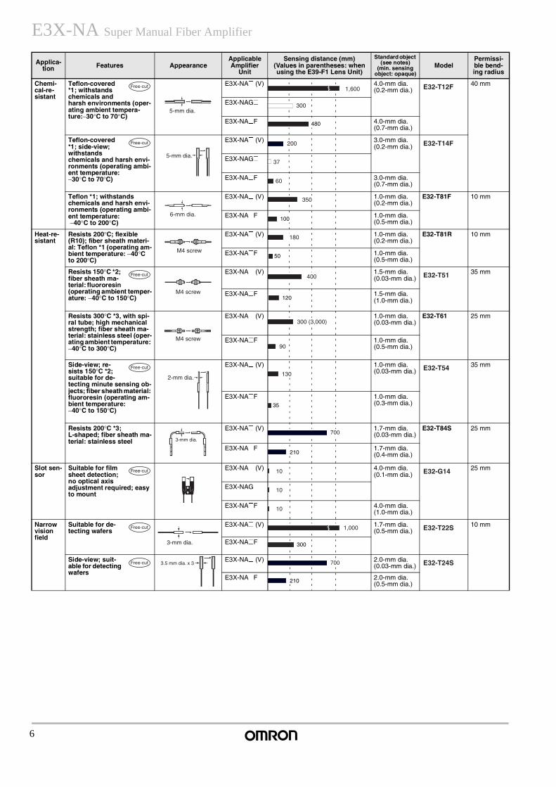
E3X-NA Super Manual Fiber Amplifier
Chemi-cal-re-sistant
Teflon-covered *1; withstands chemicals and harsh environments (oper-ating ambient tempera-ture:−30°C to 70°C)
E3X-NA@ (V) 4.0-mm dia.(0.2-mm dia.)
40 mm
E3X-NAG@
E3X-NA@F 4.0-mm dia.(0.7-mm dia.)
Teflon-covered *1; side-view; withstands chemicals and harsh envi-ronments (operating ambi-ent temperature: −30°C to 70°C)
E3X-NA@ (V) 3.0-mm dia.(0.2-mm dia.)
E3X-NAG@
E3X-NA@F 3.0-mm dia.(0.7-mm dia.)
Teflon *1; withstands chemicals and harsh envi-ronments (operating ambi-ent temperature: −40°C to 200°C)
E3X-NA@ (V) 1.0-mm dia.(0.2-mm dia.)
E32-T81F 10 mm
E3X-NA@F 1.0-mm dia.(0.5-mm dia.)
Heat-re-sistant
Resists 200°C; flexible (R10); fiber sheath materi-al: Teflon *1 (operating am-bient temperature: −40°C to 200°C)
E3X-NA@ (V) 1.0-mm dia.(0.2-mm dia.)
E32-T81R 10 mm
E3X-NA@F 1.0-mm dia.(0.5-mm dia.)
Resists 150°C *2; fiber sheath ma-terial: fluororesin (operating ambient temper-ature: −40°C to 150°C)
E3X-NA@ (V) 1.5-mm dia.(0.03-mm dia.)
35 mm
E3X-NA@F 1.5-mm dia.(1.0-mm dia.)
Resists 300°C *3, with spi-ral tube; high mechanical strength; fiber sheath ma-terial: stainless steel (oper-ating ambient temperature: −40°C to 300°C)
E3X-NA@ (V) 1.0-mm dia.(0.03-mm dia.)
E32-T61 25 mm
E3X-NA@F 1.0-mm dia.(0.5-mm dia.)
Side-view; re-sists 150°C *2; suitable for de-tecting minute sensing ob-jects; fiber sheath material: fluororesin (operating am-bient temperature: −40°C to 150°C)
E3X-NA@ (V) 1.0-mm dia.(0.03-mm dia.)
35 mm
E3X-NA@F 1.0-mm dia.(0.3-mm dia.)
Resists 200°C *3; L-shaped; fiber sheath ma-terial: stainless steel
E3X-NA@ (V) 1.7-mm dia.(0.03-mm dia.)
E32-T84S 25 mm
E3X-NA@F 1.7-mm dia.(0.4-mm dia.)
Slot sen-sor
Suitable for film sheet detection; no optical axis adjustment required; easy to mount
E3X-NA@ (V) 4.0-mm dia.(0.1-mm dia.)
25 mm
E3X-NAG@
E3X-NA@F 4.0-mm dia.(1.0-mm dia.)
Narrow vision field
Suitable for de-tecting wafers
E3X-NA@ (V) 1.7-mm dia.(0.5-mm dia.)
10 mm
E3X-NA@F
Side-view; suit-able for detecting wafers
E3X-NA@ (V) 2.0-mm dia.(0.03-mm dia.)
E3X-NA@F 2.0-mm dia.(0.5-mm dia.)
Applica-tion Features Appearance
Applicable Amplifier
Unit
Sensing distance (mm)(Values in parentheses: when using the E39-F1 Lens Unit)
Standard object (see notes)
(min. sensing object: opaque)
ModelPermissi-ble bend-ing radius
Free-cut
5-mm dia.
E32-T12F
300
480
Free-cut
5-mm dia.
200 E32-T14F
37
60
6-mm dia.
350
100
M4 screw
180
50
Free-cut
M4 screw
400 E32-T51
120
M4 screw
300 (3,000)
90
Free-cut
2-mm dia.130
E32-T54
35
3-mm dia.700
210
Free-cut 10 E32-G14
10
10
Free-cut
3-mm dia.
1,000 E32-T22S
300
Free-cut 3.5 mm dia. x 3 700 E32-T24S
210
1,600
7
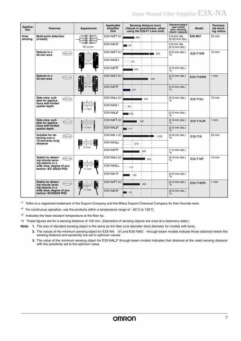
Super Manual Fiber Amplifier E3X-NA
*1 Teflon is a registered trademark of the Dupont Company and the Mitsui Dupont Chemical Company for their fluoride resin.
*2 For continuous operation, use the products within a temperature range of −40°C to 130°C.
*3 Indicates the heat-resistant temperature at the fiber tip.
*4 These figures are for a sensing distance of 100 mm. (Diameters of sensing objects are ones at a stationary state.)
Note: 1. The size of standard sensing object is the same as the fiber core diameter (lens diameter for models with lens).
2. The values of the minimum sensing object for E3X-NA@ (V) and E3X-NAG@ through-beam models indicate those obtained where thesensing distance and sensitivity are set to optimum values.
3. The value of the minimum sensing object for E3X-NA@F through-beam models indicates that obtained at the rated sensing distancewith the sensitivity set to the optimum value.
Area sensing
Multi-point detection (4-head)
E3X-NA@ (V) 2.0-mm dia.(0.03-mm dia.)
E32-M21 25 mm
E3X-NA@F 2.0-mm dia.(0.3-mm dia.)
Detects in a 30-mm area
E3X-NA@ (V) (0.5-mm dia.) *4
10 mm
E3X-NAG@
E3X-NA@F (4.0-mm dia.) *4
Detects in a 30-mm area
E3X-NA@ (V) (0.5-mm dia.) *4
1 mm
E3X-NA@F (4.0-mm dia.) *4
Side-view; suit-able for applica-tions with limited spatial depth
E3X-NA@ (V) (0.3-mm dia.) *4
10 mm
E3X-NAG@
E3X-NA@F (2.0-mm dia.) *4
Side-view; suit-able for applica-tions with limited spatial depth
E3X-NA@ (V) (0.3-mm dia.) *4
1 mm
E3X-NA@F (2.0-mm dia.) *4
Suitable for de-tecting over a 10-mm area; long distance
E3X-NA@ (V) (0.9-mm dia.) *4
25 mm
E3X-NAG@
E3X-NA@F (1.5-mm dia.) *4
Stable for detect-ing minute sens-ing objects in a wide area; degree of pro-tection: IEC 60529 IP50
E3X-NA@ (V) (0.3-mm dia.) *4
10 mm
E3X-NAG@
E3X-NA@F (2.0-mm dia.) *4
Stable for detect-ing minute sens-ing objects in a wide area; degree of pro-tection: IEC60529 IP50
E3X-NA@ (V) (0.3-mm dia.) *4
1 mm
E3X-NA@F (2.0-mm dia.) *4
Applica-tion Features Appearance
Applicable Amplifier
Unit
Sensing distance (mm)(Values in parentheses: when using the E39-F1 Lens Unit)
Standard object (see notes)
(min. sensing object: opaque)
ModelPermissi-ble bend-ing radius
M3 screw
300
90
Free-cut
30 mm
920 E32-T16W
170
270
Free-cut
30 mm
690E32-T16WR
200
Free-cut
11 mm
520 E32-T16J
95
150
Free-cut 390 E32-T16JR
110
Free-cut
10 mm
1,500 E32-T16
275
450
Free-cut
11 mm
600 E32-T16P
110
180
Free-cut 450 E32-T16PR
130
8
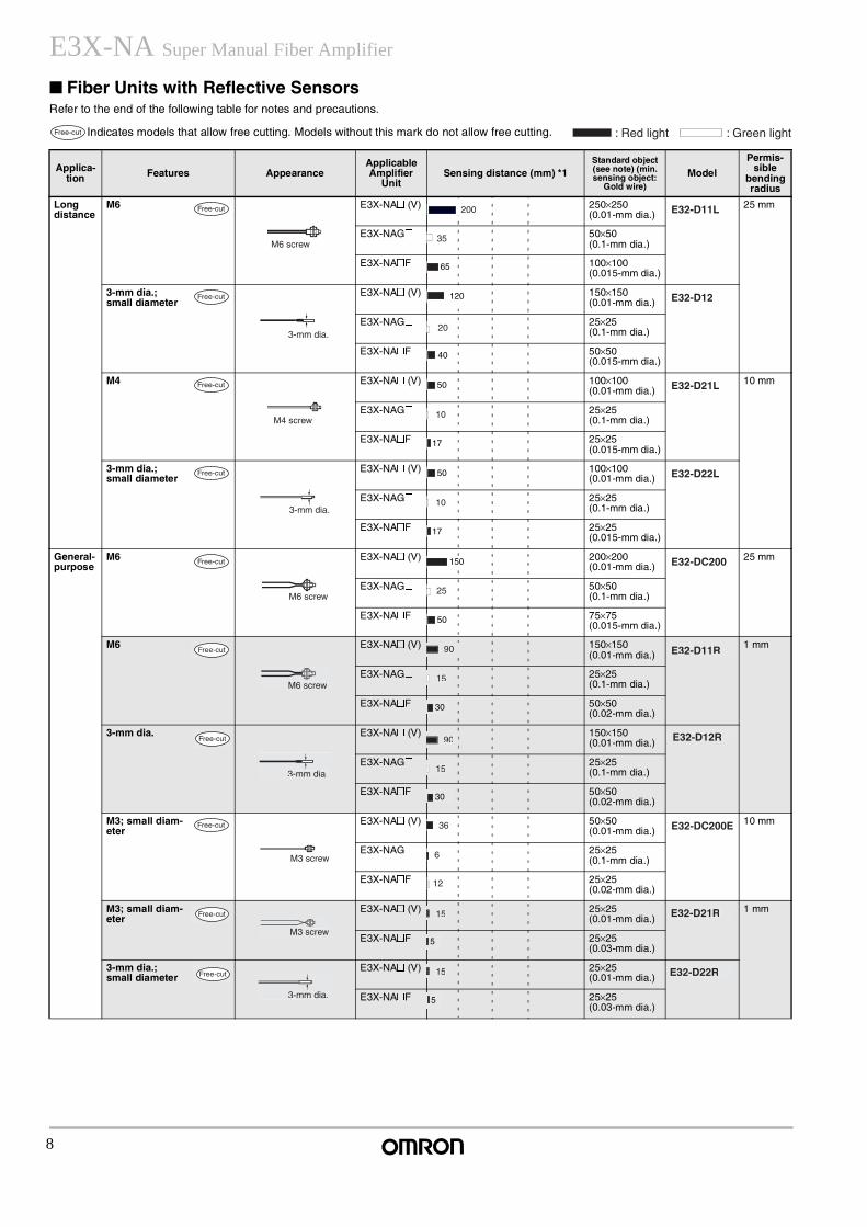
E3X-NA Super Manual Fiber Amplifier
Fiber Units with Reflective SensorsRefer to the end of the following table for notes and precautions.
Indicates models that allow free cutting. Models without this mark do not allow free cutting.
Applica-tion Features Appearance
Applicable Amplifier
UnitSensing distance (mm) *1
Standard object (see note) (min. sensing object:
Gold wire)Model
Permis-sible
bending radius
Long distance
M6 E3X-NA@ (V) 250×250 (0.01-mm dia.)
25 mm
E3X-NAG@ 50×50 (0.1-mm dia.)
E3X-NA@F 100×100 (0.015-mm dia.)
3-mm dia.; small diameter
E3X-NA@ (V) 150×150 (0.01-mm dia.)
E3X-NAG@ 25×25 (0.1-mm dia.)
E3X-NA@F 50×50 (0.015-mm dia.)
M4 E3X-NA@ (V) 100×100 (0.01-mm dia.)
10 mm
E3X-NAG@ 25×25 (0.1-mm dia.)
E3X-NA@F 25×25 (0.015-mm dia.)
3-mm dia.; small diameter
E3X-NA@ (V) 100×100 (0.01-mm dia.)
E3X-NAG@ 25×25 (0.1-mm dia.)
E3X-NA@F 25×25 (0.015-mm dia.)
General-purpose
M6 E3X-NA@ (V) 200×200 (0.01-mm dia.)
25 mm
E3X-NAG@ 50×50 (0.1-mm dia.)
E3X-NA@F 75×75 (0.015-mm dia.)
M6 E3X-NA@ (V) 150×150 (0.01-mm dia.)
1 mm
E3X-NAG@ 25×25 (0.1-mm dia.)
E3X-NA@F 50×50 (0.02-mm dia.)
3-mm dia. E3X-NA@ (V) 150×150 (0.01-mm dia.)
E3X-NAG@ 25×25 (0.1-mm dia.)
E3X-NA@F 50×50 (0.02-mm dia.)
M3; small diam-eter
E3X-NA@ (V) 50×50 (0.01-mm dia.)
10 mm
E3X-NAG@ 25×25 (0.1-mm dia.)
E3X-NA@F 25×25 (0.02-mm dia.)
M3; small diam-eter
E3X-NA@ (V) 25×25 (0.01-mm dia.)
1 mm
E3X-NA@F 25×25 (0.03-mm dia.)
3-mm dia.; small diameter
E3X-NA@ (V) 25×25 (0.01-mm dia.)
E3X-NA@F 25×25 (0.03-mm dia.)
Free-cut : Red light : Green light
Free-cut
M6 screw
200 E32-D11L
35
65
Free-cut
3-mm dia.
120 E32-D12
20
40
Free-cut
M4 screw
50 E32-D21L
10
17
Free-cut
3-mm dia.
50 E32-D22L
10
17
Free-cut
M6 screw
150 E32-DC200
25
50
Free-cut
M6 screw
90 E32-D11R
15
30
Free-cut
3-mm dia.
90 E32-D12R
15
30
Free-cut
M3 screw
36 E32-DC200E
6
12
Free-cut
M3 screw
15 E32-D21R
5
Free-cut
3-mm dia.
15 E32-D22R
5
9
Super Manual Fiber Amplifier E3X-NA
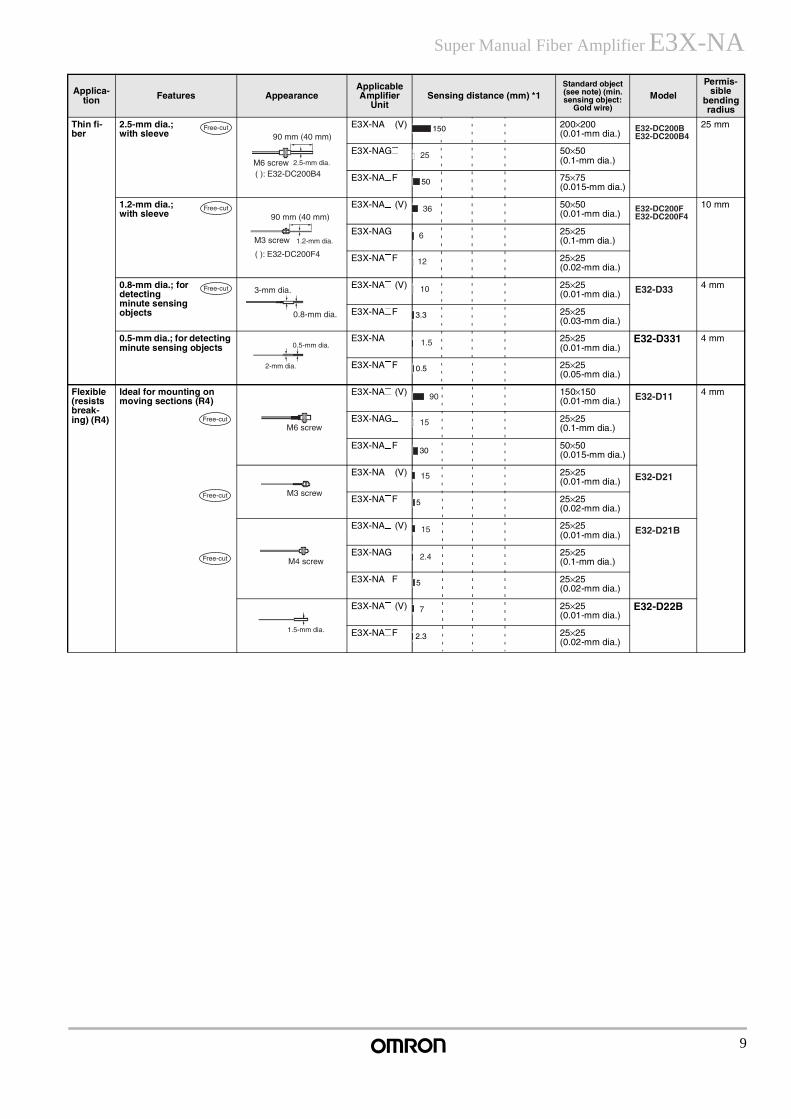
Thin fi-ber
2.5-mm dia.; with sleeve
E3X-NA@ (V) 200×200 (0.01-mm dia.)
25 mm
E3X-NAG@ 50×50 (0.1-mm dia.)
E3X-NA@F 75×75 (0.015-mm dia.)
1.2-mm dia.; with sleeve
E3X-NA@ (V) 50×50 (0.01-mm dia.)
10 mm
E3X-NAG@ 25×25 (0.1-mm dia.)
E3X-NA@F 25×25 (0.02-mm dia.)
0.8-mm dia.; for detecting minute sensing objects
E3X-NA@ (V) 25×25 (0.01-mm dia.)
4 mm
E3X-NA@F 25×25 (0.03-mm dia.)
0.5-mm dia.; for detecting minute sensing objects
E3X-NA@ 25×25 (0.01-mm dia.)
E32-D331 4 mm
E3X-NA@F 25×25 (0.05-mm dia.)
Flexible (resists break-ing) (R4)
Ideal for mounting on moving sections (R4)
E3X-NA@ (V) 150×150 (0.01-mm dia.)
4 mm
E3X-NAG@ 25×25 (0.1-mm dia.)
E3X-NA@F 50×50 (0.015-mm dia.)
E3X-NA@ (V) 25×25 (0.01-mm dia.)
E3X-NA@F 25×25 (0.02-mm dia.)
E3X-NA@ (V) 25×25 (0.01-mm dia.)
E3X-NAG@ 25×25 (0.1-mm dia.)
E3X-NA@F 25×25 (0.02-mm dia.)
E3X-NA@ (V) 25×25 (0.01-mm dia.)
E32-D22B
E3X-NA@F 25×25 (0.02-mm dia.)
Applica-tion Features Appearance
Applicable Amplifier
UnitSensing distance (mm) *1
Standard object (see note) (min. sensing object:
Gold wire)Model
Permis-sible
bending radius
Free-cut
M6 screw( ): E32-DC200B4
90 mm (40 mm)
2.5-mm dia.
150 E32-DC200BE32-DC200B4
25
50
Free-cut
M3 screw
( ): E32-DC200F4
90 mm (40 mm)
1.2-mm dia.
36 E32-DC200FE32-DC200F4
6
12
Free-cut 3-mm dia.
0.8-mm dia.
10 E32-D33
3.3
2-mm dia.
0.5-mm dia. 1.5
0.5
Free-cut
Free-cut
Free-cut
M6 screw
90 E32-D11
15
30
M3 screw
15 E32-D21
5
M4 screw
15 E32-D21B
2.4
5
1.5-mm dia.
7
2.3
10
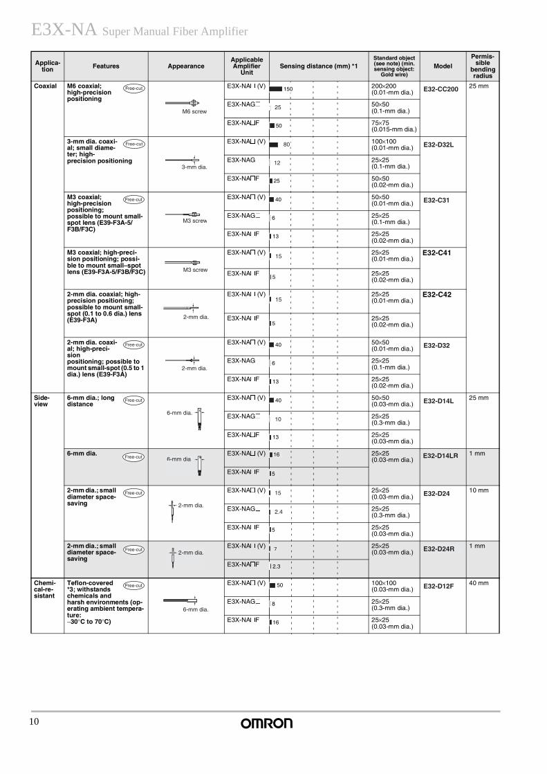
E3X-NA Super Manual Fiber Amplifier
Coaxial M6 coaxial; high-precision positioning
E3X-NA@ (V) 200×200 (0.01-mm dia.)
25 mm
E3X-NAG@ 50×50 (0.1-mm dia.)
E3X-NA@F 75×75 (0.015-mm dia.)
3-mm dia. coaxi-al; small diame-ter; high- precision positioning
E3X-NA@ (V) 100×100 (0.01-mm dia.)
E3X-NAG@ 25×25 (0.1-mm dia.)
E3X-NA@F 50×50 (0.02-mm dia.)
M3 coaxial; high-precision positioning; possible to mount small-spot lens (E39-F3A-5/F3B/F3C)
E3X-NA@ (V) 50×50 (0.01-mm dia.)
E3X-NAG@ 25×25 (0.1-mm dia.)
E3X-NA@F 25×25 (0.02-mm dia.)
M3 coaxial; high-preci-sion positioning; possi-ble to mount small–spot lens (E39-F3A-5/F3B/F3C)
E3X-NA@ (V) 25×25 (0.01-mm dia.)
E32-C41
E3X-NA@F 25×25 (0.02-mm dia.)
2-mm dia. coaxial; high-precision positioning; possible to mount small-spot (0.1 to 0.6 dia.) lens (E39-F3A)
E3X-NA@ (V) 25×25 (0.01-mm dia.)
E32-C42
E3X-NA@F 25×25 (0.02-mm dia.)
2-mm dia. coaxi-al; high-preci-sion positioning; possible to mount small-spot (0.5 to 1 dia.) lens (E39-F3A)
E3X-NA@ (V) 50×50 (0.01-mm dia.)
E3X-NAG@ 25×25 (0.1-mm dia.)
E3X-NA@F 25×25 (0.02-mm dia.)
Side-view
6-mm dia.; long distance
E3X-NA@ (V) 50×50 (0.03-mm dia.)
25 mm
E3X-NAG@ 25×25 (0.3-mm dia.)
E3X-NA@F 25×25 (0.03-mm dia.)
6-mm dia. E3X-NA@ (V) 25×25 (0.03-mm dia.)
1 mm
E3X-NA@F
2-mm dia.; small diameter space-saving
E3X-NA@ (V) 25×25 (0.03-mm dia.)
10 mm
E3X-NAG@ 25×25 (0.3-mm dia.)
E3X-NA@F 25×25 (0.03-mm dia.)
2-mm dia.; small diameter space-saving
E3X-NA@ (V) 25×25 (0.03-mm dia.)
1 mm
E3X-NA@F
Chemi-cal-re-sistant
Teflon-covered *3; withstands chemicals and harsh environments (op-erating ambient tempera-ture: −30°C to 70°C)
E3X-NA@ (V) 100×100 (0.03-mm dia.)
40 mm
E3X-NAG@ 25×25 (0.3-mm dia.)
E3X-NA@F 25×25 (0.03-mm dia.)
Applica-tion Features Appearance
Applicable Amplifier
UnitSensing distance (mm) *1
Standard object (see note) (min. sensing object:
Gold wire)Model
Permis-sible
bending radius
Free-cut
M6 screw
150 E32-CC200
25
50
Free-cut
3-mm dia.
80 E32-D32L
12
25
Free-cut
M3 screw
40 E32-C31
6
13
M3 screw
15
5
2-mm dia.
15
5
Free-cut
2-mm dia.
40 E32-D32
6
13
Free-cut
6-mm dia.
40 E32-D14L
10
13
Free-cut 6-mm dia.16 E32-D14LR
5
Free-cut
2-mm dia.
15 E32-D24
2.4
5
Free-cut2-mm dia.
7 E32-D24R
2.3
Free-cut
6-mm dia.
50 E32-D12F
8
16
11
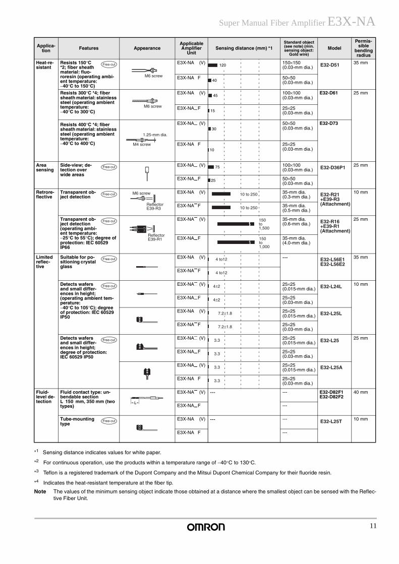
Super Manual Fiber Amplifier E3X-NA
*1 Sensing distance indicates values for white paper.
*2 For continuous operation, use the products within a temperature range of −40°C to 130°C.
*3 Teflon is a registered trademark of the Dupont Company and the Mitsui Dupont Chemical Company for their fluoride resin.
*4 Indicates the heat-resistant temperature at the fiber tip.
Note The values of the minimum sensing object indicate those obtained at a distance where the smallest object can be sensed with the Reflec-tive Fiber Unit.
Heat-re-sistant
Resists 150°C *2; fiber sheath material: fluo-roresin (operating ambi-ent temperature: −40°C to 150°C)
E3X-NA@ (V) 150×150 (0.03-mm dia.)
35 mm
E3X-NA@F 50×50 (0.03-mm dia.)
Resists 300°C *4; fiber sheath material: stainless steel (operating ambient temperature:−40°C to 300°C)
E3X-NA@ (V) 100×100 (0.03-mm dia.)
E32-D61 25 mm
E3X-NA@F 25×25 (0.03-mm dia.)
Resists 400°C *4; fiber sheath material: stainless steel (operating ambient temperature: −40°C to 400°C)
E3X-NA@ (V) 50×50 (0.03-mm dia.)
E32-D73
E3X-NA@F 25×25 (0.03-mm dia.)
Area sensing
Side-view; de-tection over wide areas
E3X-NA@ (V) 100×100 (0.03-mm dia.)
25 mm
E3X-NA@F 50×50 (0.03-mm dia.)
Retrore-flective
Transparent ob-ject detection
E3X-NA@ (V) 35-mm dia. (0.3-mm dia.)
10 mm
E3X-NA@F 35-mm dia. (0.5-mm dia.)
Transparent ob-ject detection (operating ambi-ent temperature: −25°C to 55°C); degree of protection: IEC 60529 IP66
E3X-NA@ (V) 35-mm dia. (0.6-mm dia.)
25 mm
E3X-NA@F 35-mm dia. (4.0-mm dia.)
Limited reflec-tive
Suitable for po-sitioning crystal glass
E3X-NA@ (V) --- 35 mm
E3X-NA@F
Detects wafers and small differ-ences in height; (operating ambient tem-perature: −40°C to 105°C); degree of protection: IEC 60529 IP50
E3X-NA@ (V) 25×25 (0.015-mm dia.)
10 mm
E3X-NA@F 25×25 (0.03-mm dia.)
E3X-NA@ (V) 25×25 (0.015-mm dia.)
E3X-NA@F 25×25 (0.03-mm dia.)
Detects wafers and small differ-ences in height; degree of protection: IEC 60529 IP50
E3X-NA@ (V) 25×25 (0.015-mm dia.)
25 mm
E3X-NA@F 25×25 (0.03-mm dia.)
E3X-NA@ (V) 25×25 (0.015-mm dia.)
E3X-NA@F 25×25 (0.03-mm dia.)
Fluid-level de-tection
Fluid contact type: un-bendable section L 150 mm, 350 mm (two types)
E3X-NA@ (V) --- --- E32-D82F1 E32-D82F2
40 mm
E3X-NA@F ---
Tube-mounting type
E3X-NA@ (V) --- --- 10 mm
E3X-NA@F ---
Applica-tion Features Appearance
Applicable Amplifier
UnitSensing distance (mm) *1
Standard object (see note) (min. sensing object:
Gold wire)Model
Permis-sible
bending radius
Free-cut
M6 screw
120 E32-D51
40
M6 screw
45
15
M4 screw
1.25-mm dia.30
10
Free-cut 75 E32-D36P1
25
Free-cut M6 screw
ReflectorE39-R3
10 to 250 E32-R21+E39-R3 (Attachment)
10 to 250
Free-cut
ReflectorE39-R1
150 to 1,500
E32-R16+E39-R1 (Attachment)
150 to 1,000
Free-cut 4 to12 E32-L56E1E32-L56E2
4 to12
Free-cut 4±2 E32-L24L
4±2
7.2±1.8 E32-L25L
7.2±1.8
Free-cut 3.3 E32-L25
3.3
3.3 E32-L25A
3.3
L
Free-cut E32-L25T
12
E3X-NA Super Manual Fiber Amplifier
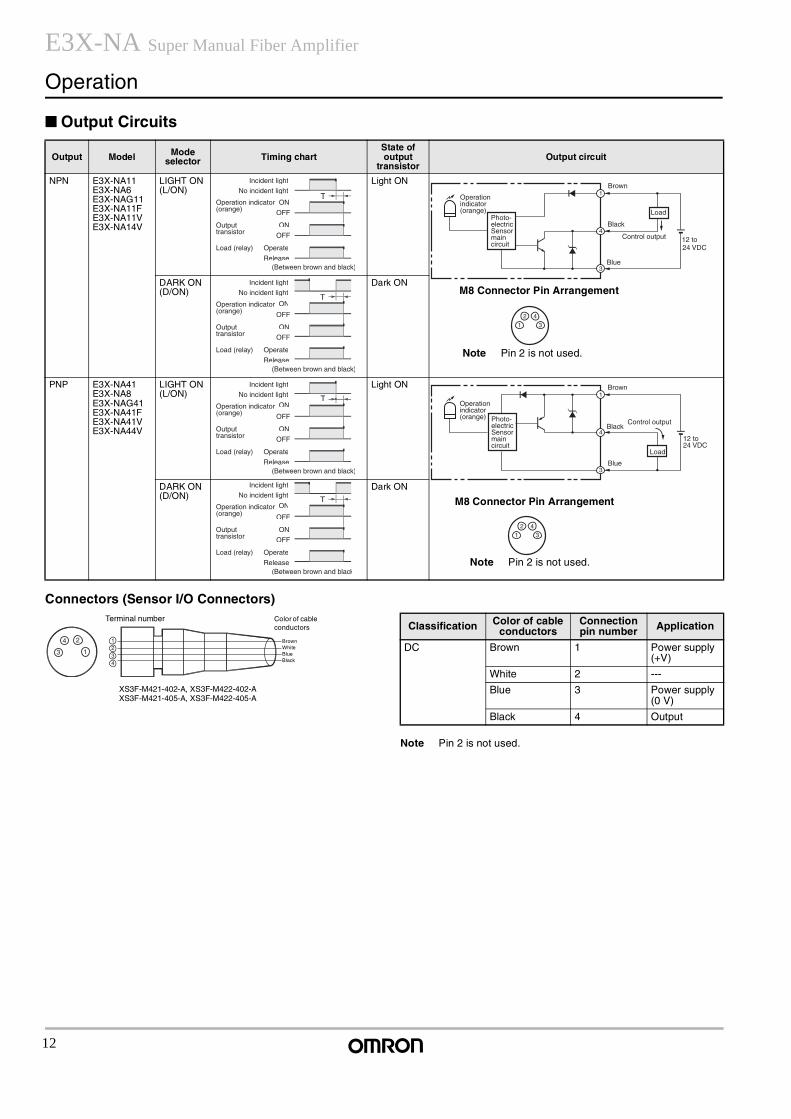
Operation
Output Circuits
Connectors (Sensor I/O Connectors)
Note Pin 2 is not used.
Output Model Mode selector Timing chart
State of output
transistorOutput circuit
NPN E3X-NA11E3X-NA6E3X-NAG11E3X-NA11FE3X-NA11VE3X-NA14V
LIGHT ON (L/ON)
Light ON
DARK ON (D/ON)
Dark ON
PNP E3X-NA41E3X-NA8E3X-NAG41E3X-NA41FE3X-NA41VE3X-NA44V
LIGHT ON (L/ON)
Light ON
DARK ON (D/ON)
Dark ON
T
ON
OFF
ON
OFF
Incident light
No incident light
Operation indicator(orange)
Output transistor
Load (relay) Operate
Release(Between brown and black)
Operation indicator (orange)
Photo-electric Sensor main circuit
Brown
Black
Control output
Blue
1
4
3
Load
12 to 24 VDC
1
2 43
Photo-electric Sensor main circuit
M8 Connector Pin Arrangement
Note Pin 2 is not used.
TON
ON
OFF
OFF
Incident light
No incident light
Operation indicator(orange)
Output transistor
Load (relay) Operate
Release(Between brown and black)
TON
ON
OFF
OFF
Incident light
No incident light
Operation indicator(orange)
Output transistor
Load (relay) Operate
Release(Between brown and black)
Operation indicator (orange)
Brown
BlackControl output
12 to 24 VDC
Blue
1
4
3
Load
1
2 43
Photo-electric Sensor main circuit
M8 Connector Pin Arrangement
Note Pin 2 is not used.
TON
ON
OFF
OFF
Incident light
No incident light
Operation indicator(orange)
Output transistor
Load (relay) Operate
Release(Between brown and black
24
13
1234
Color of cable conductors
BrownWhiteBlueBlack
XS3F-M421-402-A, XS3F-M422-402-AXS3F-M421-405-A, XS3F-M422-405-A
Terminal numberClassification Color of cable
conductorsConnection pin number Application
DC Brown 1 Power supply (+V)
White 2 ---
Blue 3 Power supply (0 V)
Black 4 Output
13
Super Manual Fiber Amplifier E3X-NA
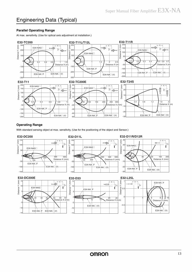
Engineering Data (Typical)
Parallel Operating Range
At max. sensitivity. (Use for optical axis adjustment at installation.)
Operating Range
With standard sensing object at max. sensitivity. (Use for the positioning of the object and Sensor.)
200
150
100
50
0
−50
−100
−150
−200
0.1 0.2 0.3 0.4 0.5 0.6 0.7
300
200
100
0
−100
−200
−300
1 2 2.5
300
200
100
0
−100
−200
−300
0.2 0.4 0.6 0.8 1 1.2
X
Y
X
Y
X
Y
E32-TC200 E32-T11L/T12L E32-T11R
Dis
tanc
e Y
(m
m)
Dis
tanc
e Y
(m
m)
Dis
tanc
e Y
(m
m)
Distance X (m) Distance X (m) Distance X (m)0.5 1.5
E3X-NAG@
E3X-NA@ (V)E3X-NA@F
E3X-NAG@
E3X-NA@F
E3X-NA@ (V)
E3X-NAG@
E3X-NA@F E3X-NA@ (V)
30
20
10
0
−10
−20
−30
0.4 0.8 1.2 1.6 2
80
60
40
20
0
−20
−40
−60
−80
50 100 150 200 250 300
200
150
100
50
0
−50
−100
−150
−200
0.2 0.4 0.6 0.8 1
X
Y
X
Y
X
Y
E32-T11 E32-T24S
Dis
tanc
e Y
(m
m)
Dis
tanc
e Y
(m
m)
Distance X (m)
E3X-NAG@
E3X-NA@F
E3X-NA@ (V)
Dis
tanc
e Y
(m
m)
Distance X (mm)
E3X-NAG@
E3X-NA@F E3X-NA@ (V)
E32-TC200E
Distance X (m)
E3X-NA@F E3X-NA@ (V)
30
20
10
0
−10
−20
−30
40 80 120 160 200
150
100
50
0
−50
−100
−150
150
100
50
0
−50
−100
−150
100 200
300 500400400
100200 300
X
Y
X
Y
X
Y
E32-DC200 E32-D11L E32-D11R/D12R
Dis
tanc
e Y
(m
m)
Dis
tanc
e Y
(m
m)
Distance X (mm)
E3X-NAG@
E3X-NA@ (V)
E3X-NA@F
Dis
tanc
e Y
(m
m)
E3X-NAG@E3X-NAG@
Distance X (mm) Distance X (mm)
E3X-NA@ (V)E3X-NA@ (V)E3X-NA@F
E3X-NA@F
1
0.5
0
−0.5
−1
15
10
5
0
−5
−10
−15
15
10
5
0
−5
−10
−15
1020 30 40 50 60 70 25
5 10 1520 4 8 102 6
X
Y
X
Y
X
Y
E32-DC200E E32-D33 E32-L25L
Dis
tanc
e Y
(m
m)
Dis
tanc
e Y
(m
m)
Distance X (mm)
Dis
tanc
e Y
(m
m)
Distance X (mm) Distance X (mm)
E3X-NAG@
E3X-NA@F E3X-NA@ (V)
E3X-NA@ (V)
E3X-NA@F
E3X-NA@ (V)
E3X-NA@F
14
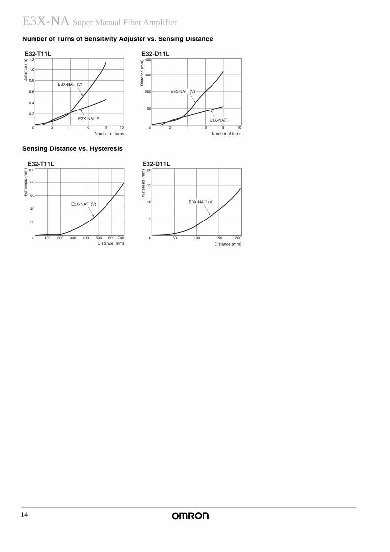
E3X-NA Super Manual Fiber Amplifier
Number of Turns of Sensitivity Adjuster vs. Sensing Distance
Sensing Distance vs. Hysteresis
E32-T11L E32-D11L
Dis
tanc
e (m
)
nsNumber of turn
Dis
tanc
e (m
m)
Number of turnsNumber of t
1.2
1.0
0.8
0.6
0.4
0.2
0 2 4 6 8 10
400
300
200
100
0 2 4 6 8 10
E3X-NA@ (V)
E3X-NA@F
E3X-NA@ (V)
@F
100
80
60
40
20
0 100 200 300 400 500 600 700
20
15
10
5
0 50 100 150 200
E32-T11L E32-D11L
Hys
tere
sis
(mm
)
Distance (mm)Distance (mm
Hys
tere
sis
(mm
)
Distance (mm)Distance
E3X-NA@ (V) E3X-NA@ (V)
15
Super Manual Fiber Amplifier E3X-NA
Application
Wiring PrecautionsRead the following before using the Amplifier Unit and Sensor to ensure safety.
Power Supply Voltage
Do not impose any voltage exceeding the rated voltage on the E3X-NA. Do not impose AC power (100 VAC) on models that operate with DC. In both cases, the E3X-NA may rupture or burn.
Load Short-circuits
Do not short-circuit the load connected to the E3X-NA, otherwise the E3X-NA may rupture or burn.
Polarity
When supplying power to the E3X-NA, make sure that the polarity of the power is correct, otherwise the E3X-NA may rupture or burn.
No-load Operation
A load must be connected to the E3X-NA during operation, otherwise internal elements may rupture or burn. Always wire through a load.
Operating Environment
• Do not use the Amplifier Unit or Sensor in places with flammable orexplosive gas.
• Do not use the Amplifier Unit or Sensor underwater.
• Do not disassemble, repair, or modify the Amplifier Unit or Sensor.
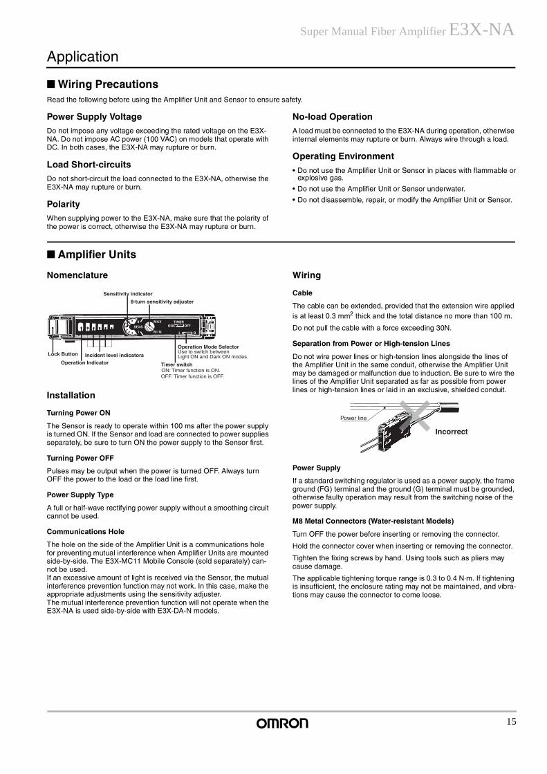
Amplifier Units
Nomenclature
Installation
Turning Power ON
The Sensor is ready to operate within 100 ms after the power supply is turned ON. If the Sensor and load are connected to power supplies separately, be sure to turn ON the power supply to the Sensor first.
Turning Power OFF
Pulses may be output when the power is turned OFF. Always turn OFF the power to the load or the load line first.
Power Supply Type
A full or half-wave rectifying power supply without a smoothing circuit cannot be used.
Communications Hole
The hole on the side of the Amplifier Unit is a communications hole for preventing mutual interference when Amplifier Units are mounted side-by-side. The E3X-MC11 Mobile Console (sold separately) can-not be used.If an excessive amount of light is received via the Sensor, the mutual interference prevention function may not work. In this case, make the appropriate adjustments using the sensitivity adjuster.The mutual interference prevention function will not operate when the E3X-NA is used side-by-side with E3X-DA-N models.
Wiring
Cable
The cable can be extended, provided that the extension wire applied is at least 0.3 mm2 thick and the total distance no more than 100 m.
Do not pull the cable with a force exceeding 30N.
Separation from Power or High-tension Lines
Do not wire power lines or high-tension lines alongside the lines of the Amplifier Unit in the same conduit, otherwise the Amplifier Unit may be damaged or malfunction due to induction. Be sure to wire the lines of the Amplifier Unit separated as far as possible from power lines or high-tension lines or laid in an exclusive, shielded conduit.
Power Supply
If a standard switching regulator is used as a power supply, the frame ground (FG) terminal and the ground (G) terminal must be grounded, otherwise faulty operation may result from the switching noise of the power supply.
M8 Metal Connectors (Water-resistant Models)
Turn OFF the power before inserting or removing the connector.
Hold the connector cover when inserting or removing the connector.
Tighten the fixing screws by hand. Using tools such as pliers may cause damage.
The applicable tightening torque range is 0.3 to 0.4 N·m. If tightening is insufficient, the enclosure rating may not be maintained, and vibra-tions may cause the connector to come loose.
Lock Button Incident level indicatorsOperation Indicator
Operation Mode SelectorUse to switch between Light ON and Dark ON modes.
Sensitivity indicator
8-turn sensitivity adjuster
Timer switchON: Timer function is ON.OFF: Timer function is OFF.
Incorrect
Power line
16
E3X-NA Super Manual Fiber Amplifier
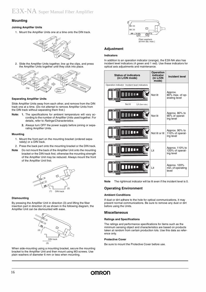
Mounting
Joining Amplifier Units
1. Mount the Amplifier Units one at a time onto the DIN track.
2. Slide the Amplifier Units together, line up the clips, and press the Amplifier Units together until they click into place.
Separating Amplifier Units
Slide Amplifier Units away from each other, and remove from the DIN track one at a time. (Do not attempt to remove Amplifier Units from the DIN track without separating them first.)
Note: 1. The specifications for ambient temperature will vary ac-cording to the number of Amplifier Units used together. Fordetails, refer to Ratings/Characteristics.
2. Always turn OFF the power supply before joining or sepa-rating Amplifier Units.
Mounting
1. Mount the front part on the mounting bracket (ordered sepa-rately) or a DIN track.
2. Press the back part onto the mounting bracket or the DIN track.
Note Do not mount the back of the Amplifier Unit onto the mountingbracket or the DIN track first, otherwise the mounting strengthof the Amplifier Unit may be reduced. Always mount the frontof the Amplifier Unit first.
Dismounting
By pressing the Amplifier Unit in direction (3) and lifting the fiber insertion part in direction (4) as shown in the following diagram, the Amplifier Unit can be dismounted with ease.
When side-mounting using a mounting bracket, secure the mounting bracket to the Amplifier Unit and then mount using M3 screws. Use plain washers of diameter 6 mm or less when mounting.
Adjustment
Indicators
In addition to an operation indicator (orange), the E3X-NA also has incident level indicators (4 green and 1 red). Use these indicators for optical axis adjustments and maintenance.
Note The rightmost indicator will be lit even if the incident level is 0.
Operating Environment
Ambient Conditions
If dust or dirt adhere to the hole for optical communications, it may prevent normal communications. Be sure to remove any dust or dirt before using the Units.
Miscellaneous
Ratings and Specifications
The ratings and performance specifications for items such as the minimum sensing object and characteristics are based on products taken at random from certain production lots. Use this data as refer-ence only.
Protective Cover
Be sure to mount the Protective Cover before use.
ClipClick into place
(1)(2)
DIN track
(4)
(3)
DIN track
Status of indicators(in L/ON mode)
Operation indicator (in L/ON mode)
Incident level
Not litApprox. 80% max. of op-erating level
Not litApprox. 80% to 90% of operat-ing level
Not lit or litApprox. 90% to 110% of operat-ing level
LitApprox. 110% to 120% of operat-ing level
LitApprox. 120% min. of operating level
Plain washers (6-mm dia. max.)
Operation indicator Incident level indicators
Not lit Lit (See note.)
17
Super Manual Fiber Amplifier E3X-NA Fiber Unit
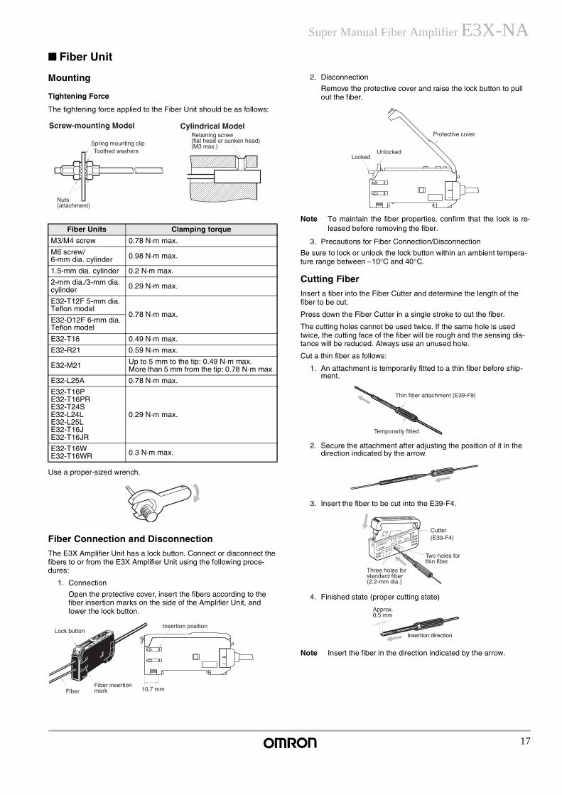
Mounting
Tightening Force
The tightening force applied to the Fiber Unit should be as follows:
Use a proper-sized wrench.
Fiber Connection and Disconnection
The E3X Amplifier Unit has a lock button. Connect or disconnect the fibers to or from the E3X Amplifier Unit using the following proce-dures:
1. Connection
Open the protective cover, insert the fibers according to the fiber insertion marks on the side of the Amplifier Unit, and lower the lock button.
2. Disconnection
Remove the protective cover and raise the lock button to pull out the fiber.
Note To maintain the fiber properties, confirm that the lock is re-leased before removing the fiber.
3. Precautions for Fiber Connection/Disconnection
Be sure to lock or unlock the lock button within an ambient tempera-ture range between −10°C and 40°C.
Cutting Fiber
Insert a fiber into the Fiber Cutter and determine the length of the fiber to be cut.
Press down the Fiber Cutter in a single stroke to cut the fiber.
The cutting holes cannot be used twice. If the same hole is used twice, the cutting face of the fiber will be rough and the sensing dis-tance will be reduced. Always use an unused hole.
Cut a thin fiber as follows:
1. An attachment is temporarily fitted to a thin fiber before ship-ment.
2. Secure the attachment after adjusting the position of it in the direction indicated by the arrow.
3. Insert the fiber to be cut into the E39-F4.
4. Finished state (proper cutting state)
Note Insert the fiber in the direction indicated by the arrow.
Fiber Units Clamping torque
M3/M4 screw 0.78 N·m max.
M6 screw/6-mm dia. cylinder 0.98 N·m max.
1.5-mm dia. cylinder 0.2 N·m max.
2-mm dia./3-mm dia. cylinder 0.29 N·m max.
E32-T12F 5-mm dia. Teflon model
0.78 N·m max.E32-D12F 6-mm dia. Teflon model
E32-T16 0.49 N·m max.
E32-R21 0.59 N·m max.
E32-M21 Up to 5 mm to the tip: 0.49 N·m max.More than 5 mm from the tip: 0.78 N·m max.
E32-L25A 0.78 N·m max.
E32-T16PE32-T16PRE32-T24SE32-L24LE32-L25LE32-T16JE32-T16JR
0.29 N·m max.
E32-T16WE32-T16WR 0.3 N·m max.
Retaining screw(flat head or sunken head)(M3 max.)
Screw-mounting Model Cylindrical Model
Spring mounting clipToothed washers
Nuts(attachment)
Lock button
FiberFiber insertion mark 10.7 mm
Insertion position
Protective cover
UnlockedLocked
Temporarily fitted
Thin fiber attachment (E39-F9)
Three holes for standard fiber (2.2-mm dia.)
Cutter (E39-F4)
Two holes for thin fiber
Approx. 0.5 mm
Insertion direction
18
E3X-NA Super Manual Fiber Amplifier
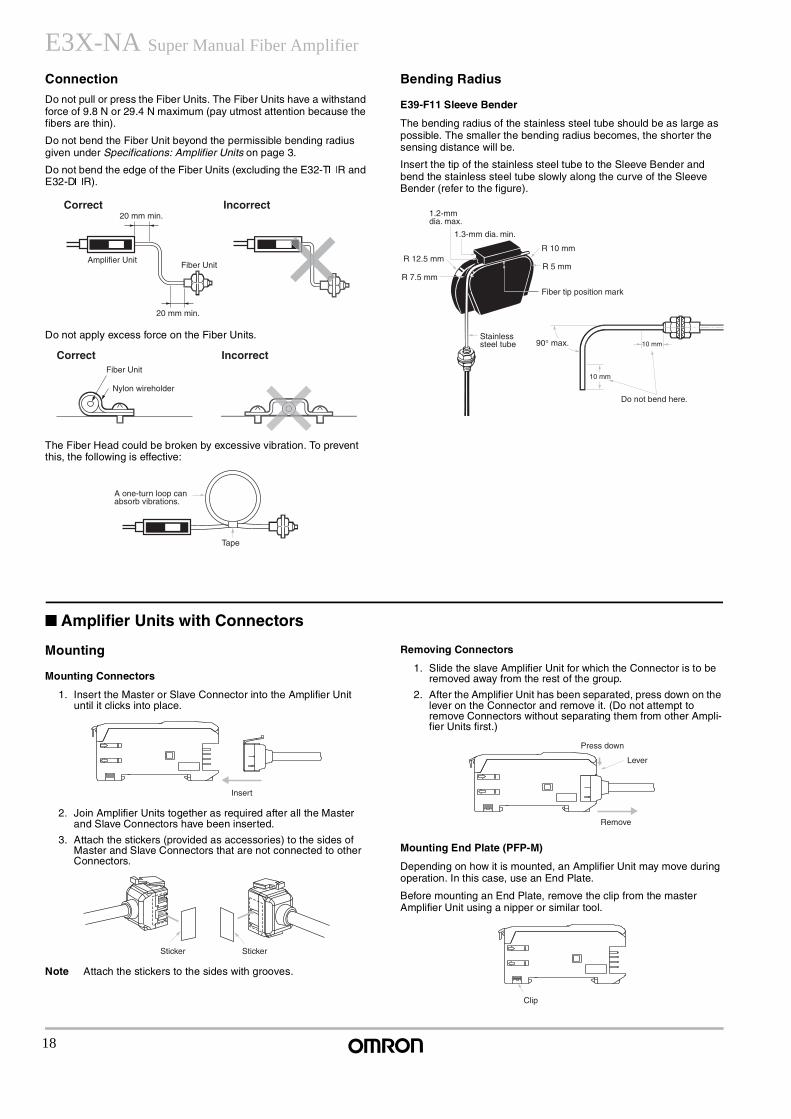
Connection
Do not pull or press the Fiber Units. The Fiber Units have a withstand force of 9.8 N or 29.4 N maximum (pay utmost attention because the fibers are thin).
Do not bend the Fiber Unit beyond the permissible bending radius given under Specifications: Amplifier Units on page 3.
Do not bend the edge of the Fiber Units (excluding the E32-T@R and E32-D@R).
Do not apply excess force on the Fiber Units.
The Fiber Head could be broken by excessive vibration. To prevent this, the following is effective:
Bending Radius
E39-F11 Sleeve Bender
The bending radius of the stainless steel tube should be as large as possible. The smaller the bending radius becomes, the shorter the sensing distance will be.
Insert the tip of the stainless steel tube to the Sleeve Bender and bend the stainless steel tube slowly along the curve of the Sleeve Bender (refer to the figure).
Amplifier Units with Connectors
Mounting
Mounting Connectors
1. Insert the Master or Slave Connector into the Amplifier Unit until it clicks into place.
2. Join Amplifier Units together as required after all the Master and Slave Connectors have been inserted.
3. Attach the stickers (provided as accessories) to the sides of Master and Slave Connectors that are not connected to other Connectors.
Note Attach the stickers to the sides with grooves.
Removing Connectors
1. Slide the slave Amplifier Unit for which the Connector is to be removed away from the rest of the group.
2. After the Amplifier Unit has been separated, press down on the lever on the Connector and remove it. (Do not attempt to remove Connectors without separating them from other Ampli-fier Units first.)
Mounting End Plate (PFP-M)
Depending on how it is mounted, an Amplifier Unit may move during operation. In this case, use an End Plate.
Before mounting an End Plate, remove the clip from the master Amplifier Unit using a nipper or similar tool.
Correct Incorrect20 mm min.
Amplifier UnitFiber Unit
20 mm min.
Fiber Unit
Nylon wireholder
Correct Incorrect
A one-turn loop can absorb vibrations.
Tape
Fiber tip position mark
Do not bend here.
1.3-mm dia. min.
1.2-mm dia. max.
R 12.5 mm
R 7.5 mm
R 10 mm
R 5 mm
Stainless steel tube 90° max. 10 mm
10 mm
Insert
Sticker Sticker
Press down
Lever
Remove
Clip
19
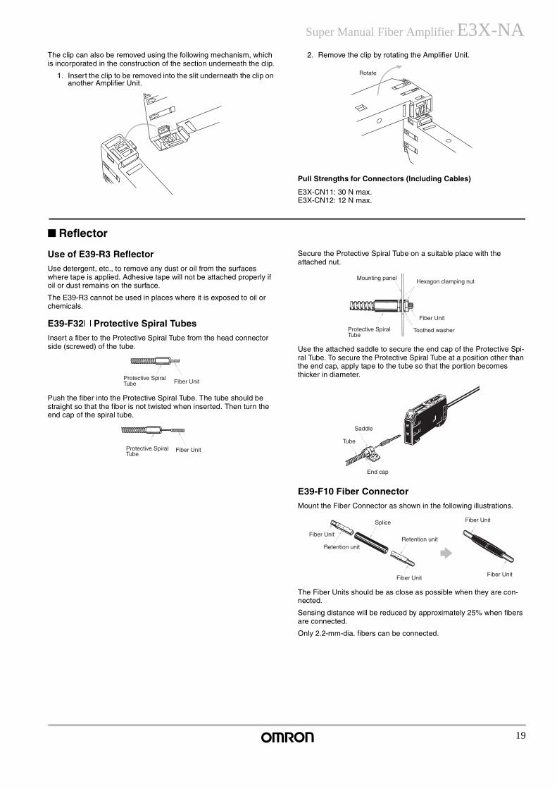
Super Manual Fiber Amplifier E3X-NAThe clip can also be removed using the following mechanism, which is incorporated in the construction of the section underneath the clip.
1. Insert the clip to be removed into the slit underneath the clip on another Amplifier Unit.
2. Remove the clip by rotating the Amplifier Unit.
Pull Strengths for Connectors (Including Cables)
E3X-CN11: 30 N max.E3X-CN12: 12 N max.
Reflector
Use of E39-R3 Reflector
Use detergent, etc., to remove any dust or oil from the surfaces where tape is applied. Adhesive tape will not be attached properly if oil or dust remains on the surface.
The E39-R3 cannot be used in places where it is exposed to oil or chemicals.
E39-F32@ Protective Spiral Tubes
Insert a fiber to the Protective Spiral Tube from the head connector side (screwed) of the tube.
Push the fiber into the Protective Spiral Tube. The tube should be straight so that the fiber is not twisted when inserted. Then turn the end cap of the spiral tube.
Secure the Protective Spiral Tube on a suitable place with the attached nut.
Use the attached saddle to secure the end cap of the Protective Spi-ral Tube. To secure the Protective Spiral Tube at a position other than the end cap, apply tape to the tube so that the portion becomes thicker in diameter.
E39-F10 Fiber Connector
Mount the Fiber Connector as shown in the following illustrations.
The Fiber Units should be as close as possible when they are con-nected.
Sensing distance will be reduced by approximately 25% when fibers are connected.
Only 2.2-mm-dia. fibers can be connected.
Rotate
Fiber UnitProtective Spiral Tube
Protective Spiral Tube
Fiber Unit
Mounting panelHexagon clamping nut
Fiber Unit
Toothed washerProtective Spiral Tube
Saddle
End cap
Tube
Splice
Retention unitRetention unit
Fiber Unit
Fiber Unit
Fiber Unit
Fiber Unit
20
E3X-NA Super Manual Fiber Amplifier
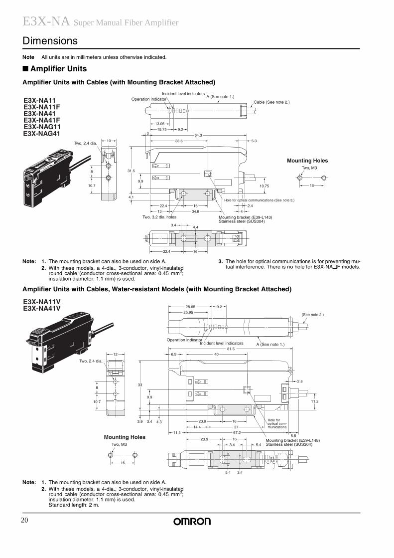
DimensionsNote All units are in millimeters unless otherwise indicated.
Amplifier Units
Amplifier Units with Cables (with Mounting Bracket Attached)
Note: 1. The mounting bracket can also be used on side A.2. With these models, a 4-dia., 3-conductor, vinyl-insulated
round cable (conductor cross-sectional area: 0.45 mm2;insulation diameter: 1.1 mm) is used.
3. The hole for optical communications is for preventing mu-tual interference. There is no hole for E3X-NA@F models.
Amplifier Units with Cables, Water-resistant Models (with Mounting Bracket Attached)
Note: 1. The mounting bracket can also be used on side A.2. With these models, a 4-dia., 3-conductor, vinyl-insulated
round cable (conductor cross-sectional area: 0.45 mm2;insulation diameter: 1.1 mm) is used. Standard length: 2 m.
8
10.7
10
3 64.3
38.6
31.5
9.9
5.3
3.4
22.4 16
4.4
4.1
13 34.8
2.422.4 16
4
10.75 16
15.75 9.2
E3X-NA11E3X-NA11FE3X-NA41E3X-NA41F
13.05
A (See note 1.)
Two, 3.2 dia. holes Mounting bracket (E39-L143) Stainless steel (SUS304)
Mounting HolesTwo, M3
Two, 2.4 dia.
Hole for optical communications (See note 3.)
Cable (See note 2.)Operation indicator
Incident level indicators
E3X-NAG11E3X-NAG41
6.9
81.5
9.228.65
25.95
12
8
10.7
4.3
9.9
3.43.9
33
23.9
14.4
11.5 67.2
37
16
1623.96.6
11.2
2.8
40
5.4
5.4
3.4
3.4
16
E3X-NA11VE3X-NA41V
A (See note 1.)
Mounting bracket (E39-L148) Stainless steel (SUS304)
Mounting HolesTwo, M3
Two, 2.4 dia.
Hole for optical com- munications
Operation indicatorIncident level indicators
(See note 2.)
21
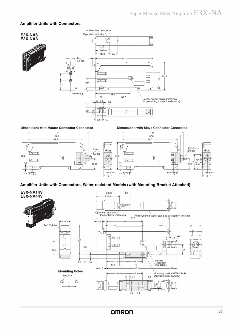
Super Manual Fiber Amplifier E3X-NAAmplifier Units with Connectors
Amplifier Units with Connectors, Water-resistant Models (with Mounting Bracket Attached)
10 64.33
8
10.79.9
3.4
38.6
13
3.95.11.7
4.2
6.2 1.7
36.7
1431.5
5.5
1.8
1.8
15.75 9.2
13.05
E3X-NA6E3X-NA8
Hole for optical communications (for preventing mutual interference)
Operation indicator
Incident level indicators
Two, 2.4 dia.
Dimensions with Master Connector Connected Dimensions with Slave Connector Connected
E3X-CN11: 4.0 dia.
E3X-CN12: 2.6 dia.
1.5
31.5
1.8 5.1 3.9
12.95
4
10
64.3
67.5
71
64.3
67.5
71
1.5
31.5
1.8 5.1 3.93
4.8
12.95 11.5517.45
4
10
6.9
81.5
12
8
10.7
4.3
9.9
3.43.9
33
23.9
14.4
11.5 67.2
37
16
1623.9
11
11.2
2.8 M8
40
5.4
5.4
3.4
3.4
16
9.228.65
25.95
E3X-NA14VE3X-NA44V
The mounting bracket can also be used on this side.
Mounting bracket (E39-L148) Stainless steel (SUS304)
Mounting HolesTwo, M3
Two, 2.4 dia.
Hole for optical com- munications
Operation indicatorIncident level indicators
22
E3X-NA Super Manual Fiber Amplifier
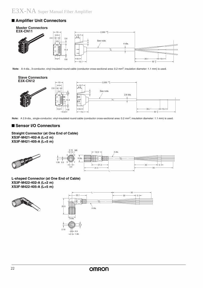
Amplifier Unit Connectors
Sensor I/O Connectors
Straight Connector (at One End of Cable)XS3F-M421-402-A (L=2 m)XS3F-M421-405-A (L=5 m)
L-shaped Connector (at One End of Cable)XS3F-M422-402-A (L=2 m)XS3F-M422-405-A (L=5 m)
Master ConnectorsE3X-CN11
Note: A 4-dia., 3-conductor, vinyl-insulated round cable (conductor cross-sectional area: 0.2 mm2; insulation diameter: 1.1 mm) is used.
See note.4 dia.
14.4
2.6
6
2.9
10
0.8 8.4
6.810.7
50 +5 0
30±2 10±2
4
15.1
6
2,000 +50 0
Slave ConnectorsE3X-CN12
Note: A 2.6-dia., single-conductor, vinyl-insulated round cable (conductor cross-sectional area: 0.2 mm2; insulation diameter: 1.1 mm) is used.
See note.
2.6 dia.
14.4
2.6
3
6
2.9
10
0.8 8.4
6.810.7
2,000 +50 0
50 +5 0
30±2 10±2
4
15.1
6
1.95 0.5
4 2
3 1
3.4
2.15 M8
L
31.4
21.5
12.9
30
50
5
4 dia.
9 dia.
1.95
0.5
3.4
2.15
L
30
50
5
20.5
23.1
4 dia.
9 dia.
23
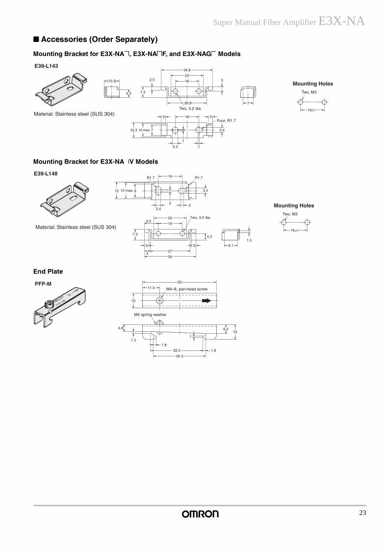
Super Manual Fiber Amplifier E3X-NA Accessories (Order Separately)
Mounting Bracket for E3X-NA@, E3X-NA@F, and E3X-NAG@ Models
Mounting Bracket for E3X-NA@V Models
End Plate
E39-L143
10 max.
Two, 3.2 dia.
Four, R1.7
Mounting HolesTwo, M3
Material: Stainless steel (SUS 304)
7
3.4
1
3163
710.3
7.35.3
(10.3) 2.5
34.8
22
16
26.8
3
3.4
1
16±0.1
E39-L148
12
1.59.1
9 3.4
2
R1.7R1.7
2
16
27
3
4
3
4.37.3
35
22
3.4
16
9.5
16±0.1
Two, 3.2 dia.
12 max.
Mounting HolesTwo, M3
Material: Stainless steel (SUS 304)
50
11.5
10
4.8
1.31.8
1.8
1
6.210
35.5
35.3
PFP-M
M4 spring washer
M4×8, pan-head screw
24
E3X-NA Super Manual Fiber Amplifier
.
In the interest of product improvement, specifications are subject to change without notice.
ALL DIMENSIONS SHOWN ARE IN MILLIMETERS.To convert millimeters into inches, multiply by 0.03937. To convert grams into ounces, multiply by 0.03527.
Cat. No. E318-E1-2
OMRON CorporationIndustrial Automation Company
Industrial Sensors DivisionSensing Devices and Components Division H.Q.Shiokoji Horikawa, Shimogyo-kuKyoto, 600-8530 Japan
Phone: (81)75-344-7068/Fax: (81)75-344-7107Printed in Japan0601-3M (0601) (A)


