

PHOTOSWITCHR Photoelectric Sensors
1--1Visit our website: www.ab.com/catalogs.Preferred availability cat. nos. are printed in bold.
General InformationQuick Selection Guide page 1--2. . . . . . . . . . . . . . . . . . . . . . .Product Application Selector page 1--14. . . . . . . . . . . . . . . .Technical Definitions & Terminology page 1--18. . . . . . . . . .Introduction page 1--19. . . . . . . . . . . . . . . . . . . . . . . . . . . . . . .
[ For information on these products, please visit our web site atwww.ab.com/catalogs.
Clear Object DetectionClearSightt page 1--147. . . . . . . . . . . . . . . . . . . . . . . . . . . . .
Label Sensors45LPT Optical Label Sensor page 1--151. . . . . . . . . . . . . . .45LFM Capacitive Label Sensor page 1--153. . . . . . . . . . . .
Fork Sensors45LSP Optical Fork Sensor page 1--155. . . . . . . . . . . . . . . .45LST Optical Fork Sensor page 1--157. . . . . . . . . . . . . . . .
Light Arrays45MLA Measuring Arrays and Controllers page 1--160. . . .45DLA Discrete Light Arrays page 1--166. . . . . . . . . . . . . . .45AST Area Arrays page 1--169. . . . . . . . . . . . . . . . . . . . . . .45PVA Verification Arrays page 1--171. . . . . . . . . . . . . . . . . .
Zero Pressure Accumulation Control44N Zone Control Sensor page 1--177. . . . . . . . . . . . . . . . . .22ZC Zone Controller page 1--180. . . . . . . . . . . . . . . . . . . . .
Hazardous LocationSeries 9000 Intrinsically Safe page 1--184. . . . . . . . . . . . . . .Series 5000 Intrinsically Safe page 1--187. . . . . . . . . . . . . . .
Vision Sensors48MS MultiSightt page 1--191. . . . . . . . . . . . . . . . . . . . . . . .
Specialty SeriesSeries 9000 Gate Entry page 1--198. . . . . . . . . . . . . . . . . . . .Series 9000 Diagnostic page 1--201. . . . . . . . . . . . . . . . . . . .Series 9000 Darkroom [. . . . . . . . . . . . . . . . . . . . . . . . . . . . .Series 6000 Compact page 1--207. . . . . . . . . . . . . . . . . . . . .Series 5000 Modular page 1--213. . . . . . . . . . . . . . . . . . . . . .Series 4000B Long Range page 1--227. . . . . . . . . . . . . . . . .Series 10,000 Teachable [. . . . . . . . . . . . . . . . . . . . . . . . . . .
Fiber Optic CablesIntroduction page 1--231. . . . . . . . . . . . . . . . . . . . . . . . . . . . . .Glass page 1--234. . . . . . . . . . . . . . . . . . . . . . . . . . . . . . . . . . .Plastic page 1--270. . . . . . . . . . . . . . . . . . . . . . . . . . . . . . . . . .Cross Reference page 1--292. . . . . . . . . . . . . . . . . . . . . . . . .
AccessoriesBrackets, Reflectors & Replacement Parts page 1--293. . .Barriers & Isolators page 12--1. . . . . . . . . . . . . . . . . . . . . . . .
IndexesCat. No. Index page 13--1. . . . . . . . . . . . . . . . . . . . . . . . . . . . .Comprehensive Product Index page 14--1. . . . . . . . . . . . . . .
General Purpose Sensors42EF RightSightt 18 mm Right Angle page 1--31. . . . . . . .42JS & 42JT VisiSightt New. . . . . . . . . . . . . . . . . . . . . . .44R AccuSightt 18 mm Right Angle page 1--48. . . . . . . . .42CA 18 mm Cylindrical page 1--52. . . . . . . . . . . . . . . . . . . .42CS Cylindrical New. . . . . . . . . . . . . . . . . . . . . . . . . . . . . . .42CM 18 mm Metal Cylindrical Style page 1--57. . . . . . . . .42CF 12 mm Metal Cylindrical page 1--62. . . . . . . . . . . . . . .
Harsh Duty SensorsSeries 9000 Standard and Timing page 1--65. . . . . . . . . . . .
Background Suppression44B Adjustable Background andForeground Suppression page 1--72. . . . . . . . . . . . . . . . . . .42BT Long Range Background Suppression page 1--76. .42BC Long Range Background Suppression page 1--78. .42BA Short-Range Background Suppression page 1--81. .
Miniature Sensors42JS VisiSightt page 1--84. . . . . . . . . . . . . . . . . . . . . . . . . . .42KA Ultra-Miniature Flat Pack page 1--88. . . . . . . . . . . . . .42KB Micro Rectangular page 1--92. . . . . . . . . . . . . . . . . . . .42KC Miniature Rectangular page 1--98. . . . . . . . . . . . . . . .Series 7000 Miniature Rectangular page 1--102. . . . . . . . . .Series 7000 LTD Miniature Rectangular page [. . . . . . . . . .
Laser SensorsLaserSightt RightSightt page 1--108. . . . . . . . . . . . . . . . . .LaserSightt 9000 page 1--112. . . . . . . . . . . . . . . . . . . . . . . .42CM LaserSightt 18 mm Cylindrical page 1--115. . . . . . .45MLD Laser Background Suppression page 1--119. . . . . .45LMS Laser Measurement New. . . . . . . . . . . . . . . . . . . . .45CPD Analog and Discrete Output page 1--121. . . . . . . . .45BPD Analog and Discrete Output page 1--123. . . . . . . . .45BRD Analog Output page 1--125. . . . . . . . . . . . . . . . . . . . .
Color Mark Sensors42CRC Color Registration Control page 1--127. . . . . . . . . . .
True Color SensorsColorSightt 9000 page 1--130. . . . . . . . . . . . . . . . . . . . . . . .45CLR ColorSightt page 1--134. . . . . . . . . . . . . . . . . . . . . .45CRM Contrast New. . . . . . . . . . . . . . . . . . . . . . . . . . . . . .
DIN Rail Mount Fiber Optic Sensors45FVL Digital Fiber Optic page 1--137. . . . . . . . . . . . . . . . . .45FSL Fiber Optic page 1--139. . . . . . . . . . . . . . . . . . . . . . . .42FT Visible Red or Green Plastic Fiber Optic page 1--14142FA Slim Fiber Optic page 1--144. . . . . . . . . . . . . . . . . . . . .45FPL Long Range New. . . . . . . . . . . . . . . . . . . . . . . . . . . .
New in this section!42CS Cylindrical42JS & 42JT VisiSight45LMS Laser Measurement45CRM Contrast45FPL Long Range
Contents

PHOTOSWITCHR Photoelectric Sensors
1--2 Visit our website: www.ab.com/catalogs.Preferred availability cat. nos. are printed in bold.
Specifications
42EFRightSightt
42KLMiniSightt
44RAccuSightt
42CA18 mm Cylindrical
Features • Patented housing design with1200 psi washdown rating
• Universal 18 mm and thru-holemounting options
• 360_ visible status indicators• DC only and universal supplymodels
• Variety of sensing modes• Variety of output types
• Industry standard housing designwith 1200 psi washdown rating
• Universal 18 mm and thru-holemounting options
• 360_ visible status indicators• 2- and 3-wire models• Variety of sensing modes• 2 m cable and micro QDconnections
• Patented status indicators• Low profile housing design• Universal 18 mm and thru-holemounting options
• 360_ visible status indicators• Low voltage DC operation• Variety of sensing modes• 2 m cable and micro QDconnections
• Industry standard 18 mm housingdesign
• Patented ASIC design offers linearsensitivity adjustment, stabilityindication, and excellent noiseimmunity
• Stability Indication for ease ofalignment and forewarning againstdetection of background
• Complementary light/dark outputs
Applications • Medium range, general purposesensing
• Washdown applications
• Medium range, general purposesensing
• Washdown applications
• Medium range, general purposesensing
• Conveyors
• Medium range, general purposesensing
• Embedded mounting
Sensing Modesand Max. Range
• Polarized retroreflective 3 m (10 ft)• Retroreflective 4.5 m (14.7 ft)• Diffuse 500 mm (20 in.)• Background suppression 50 mm(2 in.), 100 mm (4 in.)
• Transmitted beam 20 m (60 ft), 4 m(13 ft), 8 m (26 ft)
• Large aperture fiber optic• Sharp cutoff diffuse 130 mm (5 in.)
• Retroreflective 5 m (16.4 ft) or2.5 m (8.2 ft)
• Polarized retroreflective 2 m (6.6 ft)or 1 m (3.3 ft)
• Diffuse 380 mm (15 in.) or 190 mm(7.5 in.)
• Wide angle diffuse 180 mm (7 in.)or 90 mm (3.5 in.)
• Fixed focus diffuse 43 mm (1.7 in.)or 16 mm (0.63 in.)
• Transmitted beam 30 m (98 ft) or10 m (33 ft)
• Large aperture fiber optic• Small aperture fiber optic
• Polarized retroreflective 3 m (10 ft)• Diffuse 300 mm (12 in.)• Wide angle diffuse 200 mm (7.8 in.)
• Retroreflective 4.8 m (15.7 ft) and7 m (23 ft)
• Polarized retroreflective 3.8 m(12.5 ft)
• Diffuse 100, 400 and 1000 mm(3.94, 15.75, and 39.37 in.)
• Transmitted Beam 16 m (52.5 ft)
Operating Voltage • 10.8…30V DC• 21.6…264V AC/DC
• 10.8…30V DC• 21.6…250V AC/DC
• 10…30V DC • 10…30V DC
Output Type • NPN or PNP 100 mA• Dual NPN/PNP 100 mA• MOSFET 100 mA
• Dual NPN/PNP 100 mA• 2-wire AC 100 mA
• NPN or PNP 100 mA• NPN and PNP 100 mA
• NPN or PNP 100 mA
Response Time • 1…16 ms • DC = 1 ms• DC high speed=300 μs• AC = 8.3 ms
• 10 ms • 1 ms• 0.5 ms (background suppression)
Connections • 300V PVC cable 2 m• Micro and pico QD
• 300V PVC cable 2 m• Micro and pico QD
• 300V PVC cable 2 m• Micro QD (6 in.) pigtail
• 2 m cable• Micro QD
Enclosure • Mindel, Acrylic• NEMA 4X, 6P; IP67, IP69K• 1200 psi washdown
• NorylR, Acrylic• NEMA 4X, 6P; IP67• 1200 psi washdown
• ValoxR• NEMA 12; IP51
• PBT• IP67
Additional Info • See page 1--31 • See page 1--40 • See page 1--48 • See page 1--52
Quick Selection Guide
PHOTOSWITCHR Photoelectric Sensors
1--3Visit our website: www.ab.com/catalogs.Preferred availability cat. nos. are printed in bold.
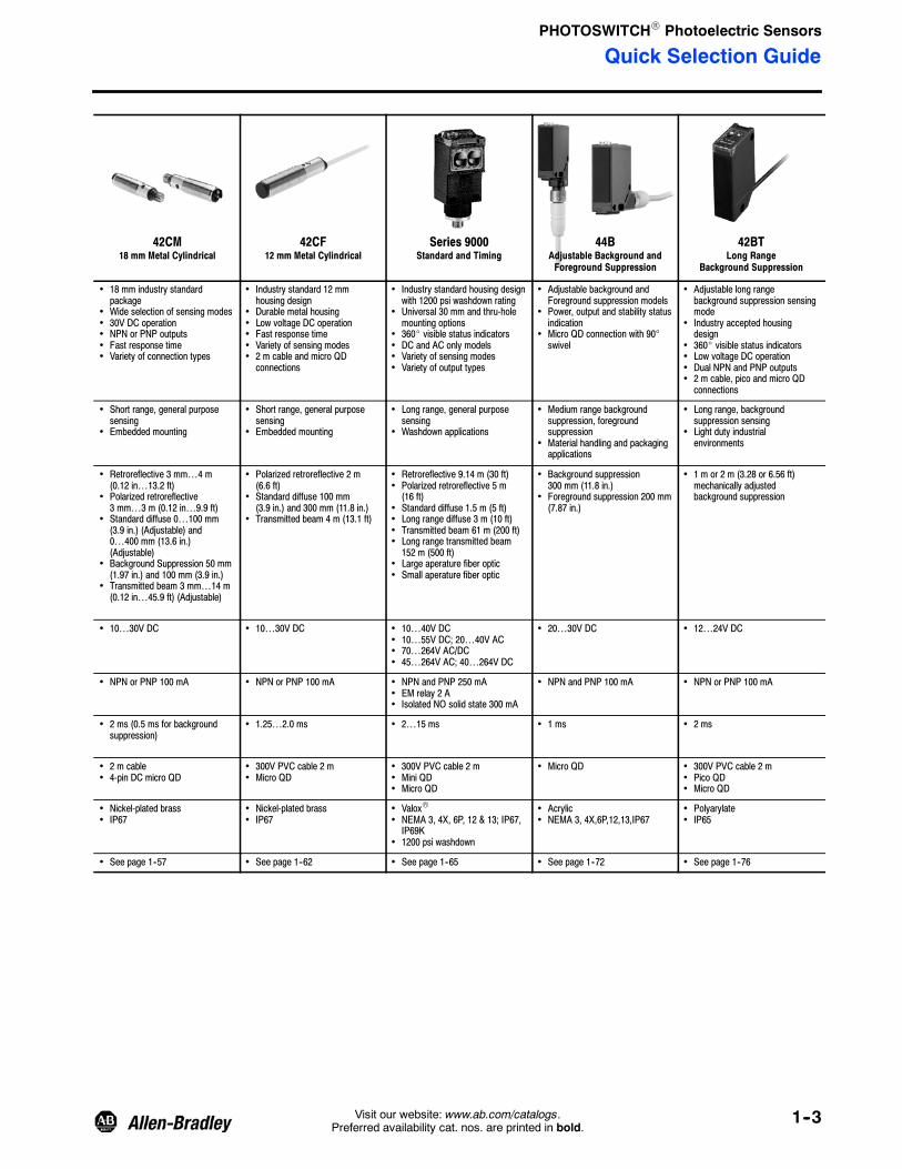
42CM18 mm Metal Cylindrical
42CF12 mm Metal Cylindrical
Series 9000Standard and Timing
44BAdjustable Background andForeground Suppression
42BTLong Range
Background Suppression
• 18 mm industry standardpackage
• Wide selection of sensing modes• 30V DC operation• NPN or PNP outputs• Fast response time• Variety of connection types
• Industry standard 12 mmhousing design
• Durable metal housing• Low voltage DC operation• Fast response time• Variety of sensing modes• 2 m cable and micro QDconnections
• Industry standard housing designwith 1200 psi washdown rating
• Universal 30 mm and thru-holemounting options
• 360_ visible status indicators• DC and AC only models• Variety of sensing modes• Variety of output types
• Adjustable background andForeground suppression models
• Power, output and stability statusindication
• Micro QD connection with 90°swivel
• Adjustable long rangebackground suppression sensingmode
• Industry accepted housingdesign
• 360_ visible status indicators• Low voltage DC operation• Dual NPN and PNP outputs• 2 m cable, pico and micro QDconnections
• Short range, general purposesensing
• Embedded mounting
• Short range, general purposesensing
• Embedded mounting
• Long range, general purposesensing
• Washdown applications
• Medium range backgroundsuppression, foregroundsuppression
• Material handling and packagingapplications
• Long range, backgroundsuppression sensing
• Light duty industrialenvironments
• Retroreflective 3 mm…4 m(0.12 in…13.2 ft)
• Polarized retroreflective3 mm…3 m (0.12 in…9.9 ft)
• Standard diffuse 0…100 mm(3.9 in.) (Adjustable) and0…400 mm (13.6 in.)(Adjustable)
• Background Suppression 50 mm(1.97 in.) and 100 mm (3.9 in.)
• Transmitted beam 3 mm…14 m(0.12 in…45.9 ft) (Adjustable)
• Polarized retroreflective 2 m(6.6 ft)
• Standard diffuse 100 mm(3.9 in.) and 300 mm (11.8 in.)
• Transmitted beam 4 m (13.1 ft)
• Retroreflective 9.14 m (30 ft)• Polarized retroreflective 5 m(16 ft)
• Standard diffuse 1.5 m (5 ft)• Long range diffuse 3 m (10 ft)• Transmitted beam 61 m (200 ft)• Long range transmitted beam152 m (500 ft)
• Large aperature fiber optic• Small aperature fiber optic
• Background suppression300 mm (11.8 in.)
• Foreground suppression 200 mm(7.87 in.)
• 1 m or 2 m (3.28 or 6.56 ft)mechanically adjustedbackground suppression
• 10…30V DC • 10…30V DC • 10…40V DC• 10…55V DC; 20…40V AC• 70…264V AC/DC• 45…264V AC; 40…264V DC
• 20…30V DC • 12…24V DC
• NPN or PNP 100 mA • NPN or PNP 100 mA • NPN and PNP 250 mA• EM relay 2 A• Isolated NO solid state 300 mA
• NPN and PNP 100 mA • NPN or PNP 100 mA
• 2 ms (0.5 ms for backgroundsuppression)
• 1.25…2.0 ms • 2…15 ms • 1 ms • 2 ms
• 2 m cable• 4-pin DC micro QD
• 300V PVC cable 2 m• Micro QD
• 300V PVC cable 2 m• Mini QD• Micro QD
• Micro QD • 300V PVC cable 2 m• Pico QD• Micro QD
• Nickel-plated brass• IP67
• Nickel-plated brass• IP67
• ValoxR• NEMA 3, 4X, 6P, 12 & 13; IP67,IP69K
• 1200 psi washdown
• Acrylic• NEMA 3, 4X,6P,12,13,IP67
• Polyarylate• IP65
• See page 1--57 • See page 1--62 • See page 1--65 • See page 1--72 • See page 1--76
Quick Selection Guide
PHOTOSWITCHR Photoelectric Sensors
1--4 Visit our website: www.ab.com/catalogs.Preferred availability cat. nos. are printed in bold.
Specifications
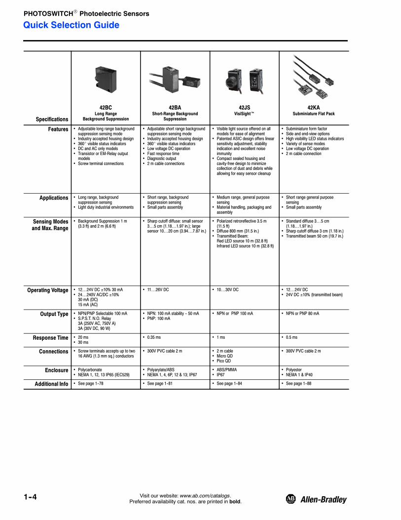
42BCLong Range
Background Suppression
42BAShort-Range Background
Suppression
42JSVisiSightt
42KASubminiature Flat Pack
Features • Adjustable long range backgroundsuppression sensing mode
• Industry accepted housing design• 360_ visible status indicators• DC and AC only models• Transistor or EM-Relay outputmodels
• Screw terminal connections
• Adjustable short range backgroundsuppression sensing mode
• Industry accepted housing design• 360_ visible status indicators• Low voltage DC operation• Fast response time• Diagnostic output• 2 m cable connections
• Visible light source offered on allmodels for ease of alignment
• Patented ASIC design offers linearsensitivity adjustment, stabilityindication and excellent noiseimmunity
• Compact sealed housing andcavity-free design to minimizecollection of dust and debris whileallowing for easy sensor cleanup
• Subminiature form factor• Side and end-view options• High visibility LED status indicators• Variety of sense modes• Low voltage DC operation• 2 m cable connection
Applications • Long range, backgroundsuppression sensing
• Light duty industrial environments
• Short range, backgroundsuppression sensing
• Small parts assembly
• Medium range, general purposesensing
• Material handling, packaging andassembly
• Short range general purposesensing
• Small parts assembly
Sensing Modesand Max. Range
• Background Suppression 1 m(3.3 ft) and 2 m (6.6 ft)
• Sharp cutoff diffuse: small sensor3…5 cm (1.18…1.97 in.); largesensor 10…20 cm (3.94…7.87 in.)
• Polarized retroreflective 3.5 m(11.5 ft)
• Diffuse 800 mm (31.5 in.)• Transmitted Beam:Red LED source 10 m (32.8 ft)Infrared LED source 10 m (32.8 ft)
• Standard diffuse 3…5 cm(1.18…1.97 in.)
• Sharp cutoff diffuse 3 cm (1.18 in.)• Transmitted beam 50 cm (19.7 in.)
Operating Voltage • 12…24V DC ±10% 30 mA• 24…240V AC/DC ±10%30 mA (DC)15 mA (AC)
• 11…26V DC • 10…30V DC • 12…24V DC• 24V DC ±10% (transmitted beam)
Output Type • NPN/PNP Selectable 100 mA• S.P.S.T. N.O. Relay3A (250V AC, 750V A)3A (30V DC, 90 W)
• NPN: 100 mA stability -- 50 mA• PNP: 100 mA
• NPN or PNP 100 mA • NPN or PNP 80 mA
Response Time • 20 ms• 30 ms
• 0.35 ms • 1 ms • 0.5 ms
Connections • Screw terminals accepts up to two16 AWG (1.3 mm sq.) conductors
• 300V PVC cable 2 m • 2 m cable• Micro QD• Pico QD
• 300V PVC cable 2 m
Enclosure • Polycarbonate• NEMA 1, 12, 13 IP65 (IEC529)
• Polyarylate/ABS• NEMA 1, 4, 6P, 12 & 13; IP67
• ABS/PMMA• IP67
• Polyester• NEMA 1 & IP40
Additional Info • See page 1--78 • See page 1--81 • See page 1--84 • See page 1--88
Quick Selection Guide

PHOTOSWITCHR Photoelectric Sensors
1--5Visit our website: www.ab.com/catalogs.Preferred availability cat. nos. are printed in bold.
42KBMicro Rectangular
42KCMiniature Rectangular
Series 7000Miniature Rectangular
Series 7000LTD Miniature Rectangular
42EFLaserSightt RightSightt
• Industry standard form factor• Diagnostic output• High visibility LED statusindicator
• Variety of sense modes• Low voltage DC operation• 2 m cable or pico QDconnections
• Industry standard form factor• Diagnostic output• High visibility LED statusindicator
• Variety of sense modes• Low voltage DC operation• 2 m cable or pico QDconnections
• Industry standard form factor• High visibility LED statusindicator
• Variety of sense modes• Complimentary light/darkoutputs
• Low voltage DC operation• 2 m cable or micro QDconnections
• Economy with performance• Industry standard form factor• High visibility LED statusindicator
• Standard sense modes• Low voltage DC operation• 2 m cable or micro QDconnections
• Universal 18 mm and thru-holemounting options
• 360° visible status indicators• Class 1 eye--safe visible laser
• Short range general purposesensing
• Small parts assembly
• Short range general purposesensing
• Small parts assembly
• Short range general purposesensing
• Small parts assembly
• Short range general purposesensing
• Small parts assembly
• Medium range, general purposesensing
• Material handling, assembly andpackaging
• Retroreflective 2 m (6.56 ft)• Standard diffuse70/200/300/400 mm(2.75/7.87/11.81/15.75 in.)
• Transmitted beam 1/7/10 m(3.3/22.75/32.8 ft)
• Sharp cutoff diffuse 30/40 mm(0.18/1.57 in.)
• Polarized retroreflective 1.5 m(5 ft)
• Standard diffuse 50 cm(19.68 in.)
• Transmitted beam 7 m (22.96 ft)
• Retroreflective 3.66 m (12 ft)• Polarized retroreflective 1.98 m(6.5 ft)
• Standard diffuse 0.30 m (12 in.)• Wide angle diffuse 0.28 m(11 in.)
• Fixed focus diffuse 17.8 mm(0.60 in.)
• Transmitted beam 7.62/9.15 m(25/30 ft)
• Small aperature fiber optic• Transparent object detection
• Retroreflective 0.76/2.13/3.65 m(2.5/7/12 ft)
• Standard diffuse 0.30 m (12 in.)• Antiglare retroreflective 1/2 m(3.28/6.5 ft)
• Polarized retroreflective 15 m(49 ft)
• Diffuse 300 mm (11.8 in.)• Transmitted Beam 40 m (131 ft)
• 11…26V DC • 11…26V DC • 11…28V DC • 11…28V DC • 10…30V DC
• NPN or PNP 100 mA • NPN or PNP 100 mA • NPN or PNP 100 mA • NPN or PNP 100 mA • NPN and PNP 100 mA
• 0.35 ms • 0.5 ms • 0.5…1 ms • 1 ms • 1 ms (4 ms for transmittedbeam)
• 300V PVC cable 2 m• Pico QD
• 300V PVC cable 2 m • PVC cable 3 m• Micro QD
• PVC cable 3 m• Micro QD
• 2 m cable• Micro QD
• Polyarylate• NEMA 1, 4, 6, 12 & 13; IP67
• Polyarylate• NEMA 1, 4, 6P, 12 & 13; IP67
• ValoxR• NEMA 3, 4X, 6P, 12 & 13; IP67
• ValoxR• NEMA 12 & 13; IP62
• Mindel/Acrylic• IP54
• See page 1--92 • See page 1--98 • See page 1--102 • www.ab.com/catalogs • See page 1--108
Quick Selection Guide
PHOTOSWITCHR Photoelectric Sensors
1--6 Visit our website: www.ab.com/catalogs.Preferred availability cat. nos. are printed in bold.
Specifications
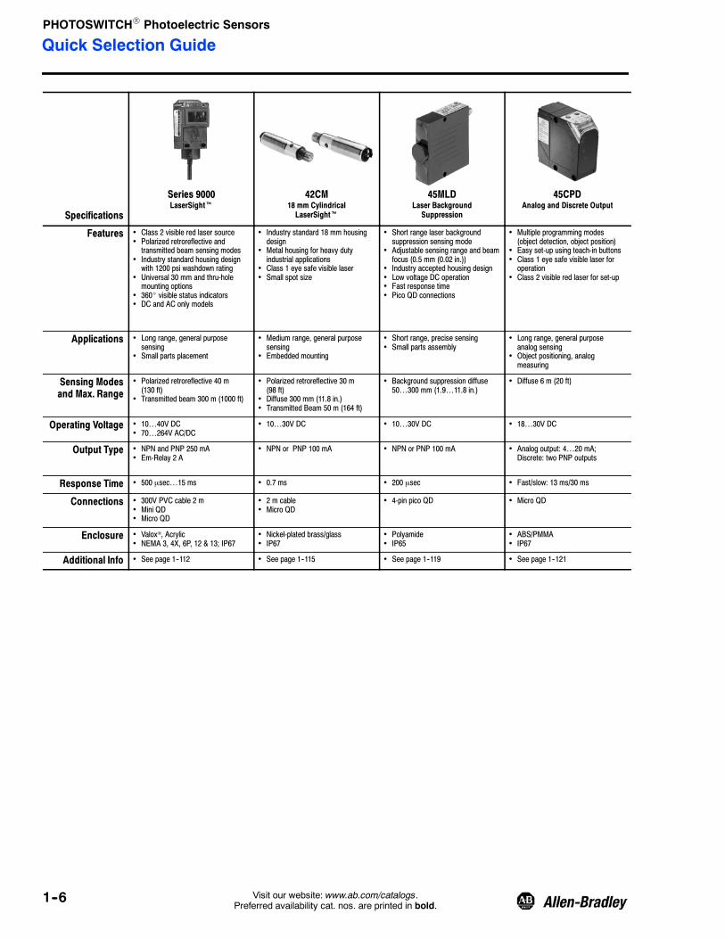
Series 9000LaserSightt
42CM18 mm CylindricalLaserSightt
45MLDLaser BackgroundSuppression
45CPDAnalog and Discrete Output
Features • Class 2 visible red laser source• Polarized retroreflective andtransmitted beam sensing modes
• Industry standard housing designwith 1200 psi washdown rating
• Universal 30 mm and thru-holemounting options
• 360_ visible status indicators• DC and AC only models
• Industry standard 18 mm housingdesign
• Metal housing for heavy dutyindustrial applications
• Class 1 eye safe visible laser• Small spot size
• Short range laser backgroundsuppression sensing mode
• Adjustable sensing range and beamfocus (0.5 mm (0.02 in.))
• Industry accepted housing design• Low voltage DC operation• Fast response time• Pico QD connections
• Multiple programming modes(object detection, object position)
• Easy set-up using teach-in buttons• Class 1 eye safe visible laser foroperation
• Class 2 visible red laser for set-up
Applications • Long range, general purposesensing
• Small parts placement
• Medium range, general purposesensing
• Embedded mounting
• Short range, precise sensing• Small parts assembly
• Long range, general purposeanalog sensing
• Object positioning, analogmeasuring
Sensing Modesand Max. Range
• Polarized retroreflective 40 m(130 ft)
• Transmitted beam 300 m (1000 ft)
• Polarized retroreflective 30 m(98 ft)
• Diffuse 300 mm (11.8 in.)• Transmitted Beam 50 m (164 ft)
• Background suppression diffuse50…300 mm (1.9…11.8 in.)
• Diffuse 6 m (20 ft)
Operating Voltage • 10…40V DC• 70…264V AC/DC
• 10…30V DC • 10…30V DC • 18…30V DC
Output Type • NPN and PNP 250 mA• Em-Relay 2 A
• NPN or PNP 100 mA • NPN or PNP 100 mA • Analog output: 4…20 mA;Discrete: two PNP outputs
Response Time • 500 μsec…15 ms • 0.7 ms • 200 μsec • Fast/slow: 13 ms/30 ms
Connections • 300V PVC cable 2 m• Mini QD• Micro QD
• 2 m cable• Micro QD
• 4-pin pico QD • Micro QD
Enclosure • Valox®, Acrylic• NEMA 3, 4X, 6P, 12 & 13; IP67
• Nickel-plated brass/glass• IP67
• Polyamide• IP65
• ABS/PMMA• IP67
Additional Info • See page 1--112 • See page 1--115 • See page 1--119 • See page 1--121
Quick Selection Guide

PHOTOSWITCHR Photoelectric Sensors
1--7Visit our website: www.ab.com/catalogs.Preferred availability cat. nos. are printed in bold.
45BPDAnalog and Discrete Output
45BRDAnalog Output
42CRCColor Registration
Series 9000ColorSightt
45CLRColorSightt
• Industry accepted 50 mm(1.97 in.) compact enclosure
• Self-contained lasermeasurement solution
• Class 2 visible red laser
• Industry accepted 50 mm(1.97 in.) compact enclosure
• 20 μm resolution• Class 2 visible red laser• 270° rotatable connector
• Selectable red or green lightsources
• Manual or teachable operation• Diagnostic output• Fast response time• Selectable pulse stretcher output• Durable IP66 housing design
• Teachable true RGB colorsensor
• Fiber optic sensing forapplication flexibility
• Industry standard housingdesign with 1200 psi washdownrating
• Universal 30 mm and thru-holemounting options
• 8 color match precision levels• Low voltage DC operation
• Three channel color matching(3 outputs)
• Wide sensing range tolerance(±6 mm (±0.24 in.))
• Adjustable tolerance for highprecision general color matching
• External teach capability• Compact size enclosure• RS--485 communication modelsavailable
• Medium range, general purposeanalog sensing
• Object positioning, analogmeasuring
• Short range, precision generalpurpose measurement
• Object positioning, analogmeasuring
• High speed contrast sensing• Color registration
• Precise color match sensing• Part inspection and sortation
• Precise color match sensing• Part inspection and sortation
• Diffuse 300 mm (11.8 in.) • Diffuse 85 mm (3.35 in.) • Color registration mark control12.7 mm (0.5 in.)
• Large aperture fiber optic • Diffuse 12…32 mm(0.47…1.26 in.)
• 18…30V DC • 18…30V DC • 10…30V DC • 10…30V DC • 18…30V DC
• Analog output: 4…20 mA;Discrete: PNP (100 mA)
• Analog output: 0…10V DC • NPN and PNP 100 mA• Diagnostic alarm NPN 30 mA
• Bipolar output • 3 PNP outputs (discrete models)• RS485 models: 1 PNP or 1 NPNoutput by cat. no.
• 0.4 ms • 30 ms • 0.25 ms • Selectable 1.5…16 ms • 1 ms
• Micro QD • Micro QD • Micro QD • 300V PVC cable 2 m• Micro QD
• Micro QD
• ABS/PMMA• IP67
• ABS/PMMA• IP67
• Epoxy-coated aluminum• NEMA 3, 4, 6, 12 & 13; IP66
• Valoxr, Acrylic• NEMA 4; IP54
• ABS/PMMA• IP67
• See page 1--123 • See page 1--125 • See page 1--127 • See page 1--130 • See page 1--134
Quick Selection Guide

PHOTOSWITCHR Photoelectric Sensors
1--8 Visit our website: www.ab.com/catalogs.Preferred availability cat. nos. are printed in bold.
Specifications
45FVLDigital Fiber Optic
45FSLSlim DIN-Rail Fiber Optic
42FT42FT Visible Red or Green
Plastic Fiber Optic
42FASlim Fiber Optic
Features • Teachable contrast sensor• Accepts all plastic fiber optic cables• Automatic and manual configurationwith LCD display
• Red, green, blue, and white lightsource models
• “Power bus” feature reduces wiring• DIN Rail mountable housing design
• Adjustable plastic fiber opticcontrast sensor
• Fast response time• Red or white light source models• “Power bus” feature reduces wiring• Crosstalk protection• DIN Rail mountable housing design
• Red or green light source• Local and remote self-teachoperation
• Supports 1.5 mm and 1.25 mmplastic fiber optic cables
• Selectable pulse-stretcher• Selectable hysteresis• Dual “RUN” modes to preventcrosstalk with other sensors
• In-line fiber optic sensor• Accepts all plastic fiber optic cables• Fast response time• Red light source models• Low voltage DC operation• DIN Rail mount option
Applications • General contrast sensing• Color registration, part inspectionand sortation
• High speed contrast sensing• Color registration, part inspectionand sortation
• General contrast sensing• Color registration, part inspectionand sortation
• Short range sensing• Small part assembly
Sensing Modesand Max. Range
• Retroreflective (bifurcated fiber)• Standard diffuse (bifurcated fiber)• Transmitted beam (individual fiber)
• Retroreflective (bifurcated fiber)• Standard diffuse (bifurcated fiber)• Transmitted beam (individual fiber)
• Small aperature fiber optic • Small aperature fiber optic
Operating Voltage • 12…24V DC • 12…24V DC • 12…24V DC • 12…24V DC ±10%• 12…24V DC ±10%
Output Type • NPN or PNP 100 mA • NPN or PNP 100 mA• Stability 100 mA
• NPN or PNP by model • NPN 100 mA• PNP 100 mA
Response Time • 600 μsec • 30 μsec, 250 μsec • 500 μsec • 500 μsec
Connections • 300V PVC cable 2 m• 4 pin pico QD• Power Bus
• 300V PVC cable 2 m• 4 pin pico QD• Power Bus
• 2 m 500V 5 conductor cable • 3-pin pico QD
Enclosure • ABS• NEMA 1 & IP40
• ABS• NEMA 1 & IP40
• ABS resin• NEMA 1, 4X, 12, 13; IP66(IEC 529)
• NorylR• NEMA 1, 12, 13; IP65 (IEC 529)
Additional Info • See page 1--137 • See page 1--139 • See page 1--141 • See page 1--144
Quick Selection Guide

PHOTOSWITCHR Photoelectric Sensors
1--9Visit our website: www.ab.com/catalogs.Preferred availability cat. nos. are printed in bold.
ClearSightt Seriesk 45LPTOptical Label Sensor
45LFMCapacitive Label Sensor
45LSPOptical Fork Sensor
45LSTOptical Fork Sensor
• Optimized for clear objectdetection
• Three types from highperformance (Series 9000, kpictured), to economical(RightSight and Series 7000)
• Washdown rated models• DC and AC only models• Variety of output types
• One-touch local and remoteteach operation
• Industrial aluminum housingdesign
• Highly visible LED statusindicators
• Low voltage DC operation• Fast response time• Pico QD connection
• Senses wide variety of labelcolors and material
• Industrial aluminum housingdesign
• Highly visible LED statusindicators
• Low voltage DC operation• Fast response time• Micro QD connection
• Teach-in sensitivity adjustment• Light or dark operate selectable• Remote teach capability (4-pinmodels)
• Plastic housing
• Ideal for small parts detection• Manual adjustment with LEDstatus indicators
• Rugged aluminum construction• Seven fork widths to choosefrom
• Fast response time• Pico QD connections
• Clear object sensing• Plastic and glass bottles, films
• Optical label sensing• Translucent labels
• Capacitive label sensing• Translucent, clear, metalizedlabels
• Smart parts detection• Beam breakage sensing
• Beam breakage sensing• Small parts assembly
• Polarized retroreflective • Transmitted beam (3 mm(0.12 in.) gap)
• Capacitive (0.76 mm (0.03 in.)gap)
• Transmitted beam gap(30…120 mm (1.18…4.72 in.))
• Transmitted beam (2…225 mm(0.08…8.86 in.) gap)
• 10…40V DC• 40…264V AC/DC• 70…264V AC/DC
• 10…30V DC • 11…30V DC • 10…30V DC • 10…30V DC
• NPN and PNP 250 mA• SPDT EM relay 2 A• Isolated NO solid state 300 mA
• NPN or PNP 100 mA • NPN or PNP 150 mA • PNP or NPN 100 mA • NPN or PNP 100 mA
• 1…10 ms • 50 μsec • 10 μsec • 250 μs • 30 μs…1 ms
• 300V PVC cable 2 m• Mini QD• Micro QD
• 4-pin pico QD • 5-pin micro QD • Pico QD • 4-pin pico QD
• ValoxR, Acrylic• NEMA 3, 4X, 6P, 12 & 13; IP67
• Aluminum• IP65
• Anodized aluminum• IP54
• Polycarbonate• IP67
• Aluminum• IP65
• See page 1--147 • See page 1--151 • See page 1--153 • See page 1--155 • See page 1--157
Quick Selection Guide

PHOTOSWITCHR Photoelectric Sensors
1--10 Visit our website: www.ab.com/catalogs.Preferred availability cat. nos. are printed in bold.
Specifications
45MLAMeasuring Arrays & Controllers
45DLADiscrete Light Arrays
45ASTArea Arrays
45PVAVerification Array
Features • Height measuring capability• Slim profile array housing• Long operating range• Fast reaction time andmeasurement speed
• Controllers available in I/O andserial communications (RS485 andCAN) models
• Integrated light array controller• Simple, flexible mounting• Optically synchronized• Wiring selectable range and outputstate (light/dark operate)
• 30mm resolution
• Two-dimensional array scanningtechnology
• 11…17 mm resolution• 50, 100, 150 mm scanning heightmodels
• Durable aluminum housing• Bracket-free mounting• Low voltage DC operation
• 35 mm object resolution• Robust aluminum enclosure• Four heights to choose from• Highly visible JOB and FAULTindicators
• Crosstalk immunity• Low voltage DC operation
Applications • Height based measurementand sorting
• Overheight/overhang detection
• Error proofing• Part detection
• Small parts assembly• Parts ejection sensing
• Error proofing• Bin picking
Sensing Modesand Max. Range
• Transmitted beam up to 4 m (13 ft) • Transmitted beam upto 8 m(26.2 ft)
• Transmitted beam up to 2.5 m(8 ft)
• Transmitted Beam 2 m (6.5 ft)
Operating Voltage • 12…24V DC • 12…24V DC • 12…24V DC • 12…24V DC
Output Type • NPN and PNP or serialcommunications (selectable bymodel)
• NPN and PNP (single push/pull) • NPN or PNP 100 mA • NPN or PNP 50 mA
Response Time • See 45MLA Controller User Manual • 25…165 ms by cat. no. • 4…8 ms • 25…98 ms
Connections • PVC cable with 8 pin micro--QD,500 mm (19.7 in) between arrayand controller
• PVC cable with 4--pin DC micro(M12), 150 mm (6 in.) cable pigtail
• 300V PVC cable 2 m • 300V PVC cable with micro QD
Enclosure • Arrays: Aluminum housing,polycarbonate lens, IP54
• Controller: ABS housing IP54• Terminal strip: IP20
• Aluminum housing,polycarbonate lens
• IP54
• Aluminum housing, acrylic window• IP67
• Aluminum housing, acrylic window• IP62
Additional Info • See page 1--160 • See page 1--166 • See page 1--169 • See page 1--171
Quick Selection Guide

PHOTOSWITCHR Photoelectric Sensors
1--11Visit our website: www.ab.com/catalogs.Preferred availability cat. nos. are printed in bold.
44NZone Control Sensor
22ZCZone Controller
Series 9000Intrinsically Safe
Series 5000Intrinsically Safe
• Integral zone control logic• Supports singulation and slug operation• Compatible with variety of valves• Polarized retroreflective sense mode• Durable housing and connections• Low voltage DC operation
• Selectable pneumatic or powered rollerzone control logic
• Selectable advanced zone logic functions• Selectable RUN/STOP delay timers• Accepts mechanical or photoelectricsensor inputs
• Drives pneumatic valve or powered rollerdriver
• Proven flat cable IDC technology
• FM approved intrinsically safe design• Transmitted beam sensing mode• Compatible with Series 897H IS barriers• Industry standard housing design with1200 psi washdown rating
• Universal 30 mm and thru-hole mountingoptions
• 360_ visible status indicators
• FM approved intrinsically safe design• Multiple sensing modes• Compatible with Series 897H IS barriers• Modular housing design• Screw terminal connections
• Zero pressure accumulation conveyors• Pneumatically driven systems
• Accumulation conveyors• Pneumatically and powered roller drivensystems
• Intrinsically safe systems• Hazardous (Classified) locations
• Intrinsically safe systems• Hazardous (Classified) locations
• Polarized Retroreflective 50.8…4.87 m(2…16 ft)
• Compatible with a wide variety ofphotoelectric and mechanical switches
• Transmitted Beam• 106 m (350 ft)
• Retroreflective 10 m (33 ft)• Polarized retroreflective 6 m (20 ft)• Standard diffuse 2.1 m (7 ft)• Large aperature fiber optic/fixedfocus/wide angle diffuse
• 10…30V DC • 24V DC • 13…30V DC25 mA
• 13…29.5V DC
• PNP 100 mA • Output signal for powered roller and drivefor pneumatic valve
• PNP/8.5 mANPN/15 mA
• NPN and PNP 20 mA at 29.5V DC
• Variable 200 ms…10 s • 1 ms • 10 ms max. • 1 ms
• 838 mm (33 in.) pigtail• 381 mm (15 in.) pigtail• Pico (M8) connector
• IDC flat cable • 2 m 300V cable• 4-pin micro QD• 4-pin mini QD
• Screw terminals
• ValoxR• NEMA 4, 4X, 6, 12, IP67
• ValoxR• NEMA 1, IP20 (IEC 529)
• ValoxR• NEMA 3, 4X, 6P, 12, 13, IP67, 1200 psiwashdown
• ValoxR• NEMA 3, 4, 12, 13 (IP66)
• See page 1--177 • See page 1--180 • See page 1--184 • See page 1--187
Quick Selection Guide

PHOTOSWITCHR Photoelectric Sensors
1--12 Visit our website: www.ab.com/catalogs.Preferred availability cat. nos. are printed in bold.
Specifications
48MSMultiSightt
Series 9000Gate Entry
Series 9000Diagnostic
Series 9000Darkroom
Features • Ten or 32 virtual detectors• Standalone vision sensor• Compact, sturdy industrial housingwith IP67 rating
• Optional EtherNet/IP with RSLogix5000 Add-On profile for I/O data
• Multiple evaluation methods:pattern matching, brightness,contrast and contour matching.
• UL325 and UL508 approved• Industry standard housing designwith 1200 psi washdown rating
• Offered as kits or individualcomponents
• Selectable static or dynamicoperation
• Industry standard housing designwith 1200 psi washdown rating
• Universal 30 mm (1.18 in.) andthru-hole mounting options
• 360_ visible status indicators• DC and AC only models• Variety of sensing modes
• 880 nm wavelength for darkroomapplications
• Fast response time• Industry standard housing design• DC and AC only models• Variety of sensing modes• Variety of output types
Applications • Error proofing applications• Packaging, assembly
• Automatic access control• Vehicle access systems
• Long range, general purposesensing
• Requirement for diagnostic output
• Darkroom, general purpose sensing• Film processing
Sensing Modesand Max. Range
• Vision sensor (infinite depending onlighting conditions)
• Retroreflective 9 m (30 ft)• Transmitted beam 61 m (200 ft)
• Retroreflective 9.14 m (30 ft)• Polarized retroreflective 5 m (16 ft)• Standard diffuse 1.5 m (5 ft)• Transmitted beam 61 m (200 ft)
• Retroreflective 9.14 m (30 ft)• Standard diffuse 0.91 m (3 ft)• Transmitted beam 30 m (100 ft)
Operating Voltage • 24V DC • 10…55V DC/20…40V AC• 70…264V AC/DC
• 10…30V DC• 90…264V AC95…264V DC
• 10…40V DC• 70…264V AC/DC
Output Type • 4 x PNP (200 mA per output) • SPDT EM Relay • Switch selectable NPN and PNPNO—NC 100 mA
• EM relay: sensor -- 2 A diagnostic --1 A
• NPN and PNP 250 mA• SPDT EM relay, 2 A
Response Time • 50…250 ms • 23 ms • 2…15 ms • 2…23 ms
Connections • Power I/O• Ethernet
• 2 m cable• AC mini QD
• Mini quick-disconnect• Micro quick-disconnect
• 300V PVC cable 2 m• Mini quick-disconnect• Micro quick-disconnect
Enclosure • Polycarbonate• IP67
• Valox/Acrylic• NEMA 2, 4, 4X, 6P, IP67, 1200 psi(8270 kPa) washdown
• ValoxR• NEMA 3, 4X, 6P, 12 & 13; IP67
• NEMA 3,4X, 6P, 12 & 13; IP67
Additional Info • See page 1--191 • See page 1--198 • See page 1--201 • www.ab.com/catalogs
Quick Selection Guide

PHOTOSWITCHR Photoelectric Sensors
1--13Visit our website: www.ab.com/catalogs.Preferred availability cat. nos. are printed in bold.
Series 6000Compact
Series 5000Modular
Series 4000BLong Range
Series 10,000Teachable
• Compact cylindrical housing design• Manual sensitivity adjustment• Dual NPN and PNP outputs• Variety of sense modes• DC and AC only models• 2 m cable and micro QD connections
• Multiple connection base and photoheadoptions
• Multiple plug-in output modules• Multiple plug-in logic modules• DC and AC only models
• Durable housing design• DC and AC only models• Variety of sensing modes• Multiple plug-in output modules• Multiple plug-in logic modules• Screw terminal connections
• Manual or teachable operation• LCD display for easy setup• Automatic sensitivity control withdiagnostic output
• Industry standard housing design with1200 psi washdown rating
• Low voltage DC operation• Variety of sensing modes
• Medium range, general purpose sensing• Cold temperature environments
• Long range, general purpose sensing• Modular approach for maximum flexibility
• Long range, general purpose sensing• Harsh duty installations
• Precise contrast sensing• Small parts assembly
• Retroreflective 8.5 m (28 ft)• Polarized retroreflective 3 m (10 ft)• Standard diffuse 0.76 m (30 in.)• Wide angle diffuse 0.46 m (18 in.)• Fixed focus diffuse 27.9 mm(1.1 in.)
• Transmitted beam 36.5 m (120 ft)• Large aperture fiber optic• Small aperture fiber optic• Sharp cutoff diffuse 0.25…7.6 cm(0.1…3 in.)
• Retroreflective 6…10 m (20…33 ft)• Polarized retroreflective 6 m (20 ft)• Standard diffuse 1.5…3 m (5…10 ft)• Background suppression diffuse6.3…30.5 cm (2.5…12 in.)
• Wide angle diffuse 0.46 m (18 in.)• Fixed focus diffuse 50.8 mm (2.0 in.)• Large aperture fiber optic
• Retroreflective 10.6 m (35 ft)• Polarized retroreflective 7 m (23 ft)• Standard diffuse 3.6 m (12 ft)• Transmitted beam 274 m (900 ft)
• ClearSight 1.2 m (48 in.)• Retroreflective 9 m (30 ft)• Polarized retroreflective 4.6 m (15 ft)• Standard diffuse 2.7 m (8.9 ft)• Large aperature fiber optic• Small aperature fiber optic• Green fiber optic
• 10…30V DC• 20…132V AC/DC• 20…264V AC/DC
• 102…132V AC• 204…254V AC• 10…30V DC• 40…54V AC/DC• 20…30V AC/DC
• 102…132V AC• 195…253V AC• 40…58V AC• 18…28V AC/DC
• 10…30V DC
• NPN and PNP 220 mA• Power MOSFET 150…300 mA
• EM relay 2 A• Triac 750 mA• FET 30 mA• NPN and PNP 100 mA
• EM relay 5 A• Triac 1 A• FET 30 mA• NPN 250 mA• DCV 30 mA
• NPN and PNP• Diagnostic alarm, NPN or PNP
• 0.2…18 ms • 1…20 ms • 5…20 ms • Selectable 250 μsec…4 ms
• PVC cable 3 m • Vinyl cable 3 m• Screw terminals• Mini QD
• Terminals • 300V PVC cable 2 m• Mini QD• Micro QD
• NorylR• NEMA 3, 4X 6, 12 & 13; IP67
• ValoxR• NEMA 3, 4, 12 & 13; IP66
• NorylR• NEMA 3, 4, 12 & 13; IP66
• ValoxR• NEMA 3, 4X, 6P, 12 & 13; IP67
• See page 1--207 • See page 1--213 • See page 1--227 • www.ab.com/catalogs
Quick Selection Guide

PHOTOSWITCHR Photoelectric Sensors
1--14 Visit our website: www.ab.com/catalogs.Preferred availability cat. nos. are printed in bold.
Standard Industrial Application Sensing Modes Maximum Sensing Range Series Page
Objectto beSensed
Retroreflective4.8 m (15.7 ft) 42CA 1--52
7.2 m (23.6 ft) 42CA 1--52
Retroreflective
4.5 m (14.7 ft) RightSight 1--31
5 m (16.4 ft) MiniSight 1--40
9 m (30 ft) Series 9000 1--68
Polarized Retroreflective
3 m (9.8 ft) AccuSight 1--48
3 m (9.8 ft) RightSight 1--31
3 m (9.8 ft) 42CA 1--52
2 m (6.6 ft) MiniSight 1--40
5 m (16 ft) Series 9000 1--69
Objectto beSensed
Standard Diffuse
500 mm (20 in.) RightSight 1--31
380 mm (15 in.) MiniSight 1--40
380 mm (1.5 in.) AccuSight 1--48
1.5 m (5 ft) Series 9000 1--69
400 mm (13.6 in.) 42CA 1--52
100 mm (4 in.) 42CA 1--52
1000 mm (39.4 in.) 42CA 1--52
Objectto beSensed
Background Suppression
50 mm (2 in.) RightSight 1--31
300 mm (11.8 in.) 44B 1--72
100 mm (4 in.) RightSight 1--31
1 m (3.3 ft) 42BT 1--76
2 m (6.5 ft) 42BC 1--78
1 m (3.3 ft) 42BT 1--76
2 m (6.5 ft) 42BC 1--78
30 mm (1.2 in.) 42BA 1--81
50 mm (2 in.) 42CA 1--52
50 mm (2 in.) 42BA 1--81
100 mm (4 in.) 42CA 1--52
100 mm (4 in.) 42BA 1--81
200 mm (8 in.) 42BA 1--81
Sharp Cutoff Diffuse
100 mm (4 in.) AccuSight 1--48
130 mm (5 in.) RightSight 1--31
30 mm (1.2 in.) 42KA 1--88
30 mm (1.2 in.) 42KB 1--96
40 mm (1.6 in.) 42KB 1--96
Objectto beSensed
Transmitted Beam
4 m (15 ft) RightSight 1--31
16 m (52.5 ft) 42CA 1--52
20 m (65 ft) RightSight 1--31
20 m (65 ft) MiniSight 1--40
61 m (200 ft) Series 9000 1--65
152 m (500 ft) Series 9000 1--65
Product Application Selector

PHOTOSWITCHR Photoelectric Sensors
1--15Visit our website: www.ab.com/catalogs.Preferred availability cat. nos. are printed in bold.
Standard Industrial Application Sensing Modes Maximum Sensing Range Series Page
Objectto beSensed
Fiber Optic, Infrared Glass
Varies with FO cable MiniSight 1--40
Varies with FO cable RightSight 1--31
Varies with FO cable Series 9000 1--65
Fiber Optic, Visible RedPlastic
Varies with FO cable MiniSight 1--40
Varies with FO cable Series 9000 1--65
Varies with FO cable 45FVL 1--137
Varies with FO cable 42FA 1--144
Varies with FO cable 45FSL 1--139
Fiber Optic, Visible GreenPlastic Varies with FO cable 45FVL 1--137
Fiber Optic, Visible BluePlastic Varies with FO cable 45FVL 1--137
Fiber Optic, Visible WhitePlastic
Varies with FO cable 45FSL 1--139
Varies with FO cable 45FVL 1--137
Clear Bottles, Films
Clear Object
1.4 m (4.5 ft)ClearSight 9000 1--147
ClearSight 10000 1--147
1.5 m (5 ft) ClearSight 7000 1--150
1 m (3.28 ft) ClearSight RightSight 1--150
Color Registration
Color Recognition
Up to 25.5 mm (1 in.) ColorSight 1--130
12…32 mm (0.4…1.26 in.) 45CLR ColorSight 1--134
Color Registration
Contrast
Up to 12 mm (0.5 in.) 45FVL 1--137
12.7 mm (0.5 in.) 42CRC 1--127
Long Range Sensing
Objectto beSensed
Transmitted Beam 152 m (500 ft) Series 9000 1--65
Laser 300 m (1000 ft) LaserSight 1--112
High Temperature (70…480_C) Fiber Optic Varies with FO cable 45FVL 1--137
Fiber Optic Varies with FO cable 42FT 1--141
Fiber Optic Varies with FO cable 45FSL 1--139
Fiber Optic Varies with FO cable RightSight 1--31
Fiber OpticVaries with FO cable MiniSight 1--40
Varies with FO cable Series 9000 1--65
Product Application Selector

PHOTOSWITCHR Photoelectric Sensors
1--16 Visit our website: www.ab.com/catalogs.Preferred availability cat. nos. are printed in bold.
Standard Industrial Application Sensing Modes Maximum Sensing Range Series Page
High Speed (250 ms or better)
Retroreflective 5 m (16.4 ft) MiniSight 1--40
Polarized Retroreflective 2 m (6.6 ft) MiniSight 1--40
Standard Diffuse 380 mm (15 in.) MiniSight 1--40
Wide Angle Diffuse 180 mm (7 in.) MiniSight 1--40
Transmitted Beam 30 m (98 ft) MiniSight 1--40
Glass (Infrared) Fiber Optic Varies with FO cable MiniSight 1--40
Plastic (Visible) Fiber OpticVaries with FO cable MiniSight 1--40
Varies with FO cable 45FSL 1--139
Hazardous (Classified) Location
Retroreflective 10 m (33 ft) Series 5000 1--213
Polarized Retroreflective 6 m (20 ft) Series 5000 1--213
Standard Diffuse 2 m (7 ft) Series 5000 1--213
Fixed Focus Diffuse 50 mm (2 in.) Series 5000 1--213
Wide Angle Diffuse 500 mm (20 in.) Series 5000 1--213
Transmitted Beam 106 m (350 ft) Series 9000 1--186
Glass Fiber Optic Varies with FO cable Series 5000 1--213
Analog Output
DCCurrent(mA)
Operating Distance
PositiveSlope Negative
Slope
Retroreflective 4.6 m (15 ft) Series 5000 1--213
Standard Diffuse 1.5 m (5 ft) Series 5000 1--213
Fixed Focus Diffuse 50 mm (2 in.) Series 5000 1--213
Wide Angle Diffuse 500 mm (20 in.) Series 5000 1--213
Glass (Infrared) Fiber Optic 500 mm (20 in.) Series 5000 1--213
Retroreflective 9 m (30 ft) SmartSight 9000 10--10
Polarized Retroreflective3 m (9.8 ft) RightSight 10--4
5 m (16 ft) SmartSight 9000 10--10
Standard Diffuse500 mm (20 in.) RightSight 10--6
1.5 m (5 ft) SmartSight 9000 10--11
Transmitted Beam
4 m (15 ft) RightSight 10--7
20 m (65 ft) RightSight 10--7
61 m (200 ft) SmartSight 9000 10--11
130 m (425 ft) SmartSight 9000 10--11
Fiber Optic, Infrared GlassVaries with FO cable RightSight 10--7
Varies with FO cable SmartSight 9000 10--11
Product Application Selector

PHOTOSWITCHR Photoelectric Sensors
1--17Visit our website: www.ab.com/catalogs.Preferred availability cat. nos. are printed in bold.
Miniature-UltraMiniature Sensors Sensing Modes Maximum Sensing Range Series Page
Retroreflective2 m (6.5 ft) 42KB 1--95
3.6 m (12 ft) Series 7000 1--102
Polarized Retroreflective
1.5 m (4.9 ft) 42KC 1--98
2 m (6.5 ft) Series 7000 1--102
2 m (6.5 ft) 42CF 1--62
3.5 m (11.5 ft) 42JS 1--84
Standard Diffuse
30 mm (1.2 in.) 42KA 1--88
50 mm (2 in.) 42KA 1--88
70 mm (2.8 in.) 42KB 1--96
200 mm (8 in.) 42KB 1--96
300 mm (11.8 in.) 42KB 1--96
400 mm (15.8 in.) 42KB 1--96
500 mm (20 in.) 42KC 1--98
100 mm (4 in.) 42CF 1--62
300 mm (11.8 in.) 42CF 1--62
300 mm (11.8 in.) Series 7000 1--102
800 mm (31.5 in.) 42JS 1--84
Background Suppression
30 mm (1.2 in.) 42BA 1--81
50 mm (2 in.) 42BA 1--81
100 mm (4 in.) 42BA 1--81
200 mm (8 in.) 42BA 1--81
Sharp Cutoff Diffuse
30 mm (1.2 in.) 42KA 1--88
30 mm (1.2 in.) 42KB 1--96
40 mm (1.6 in.) 42KB 1--96
Wide Angle Diffuse 280 mm (11 in.) Series 7000 1--102
Transmitted Beam
500 mm (20 in.) 42KA 1--88
1 m (3.3 ft) 42KB 1--97
7 m (23 ft) 42KB 1--97
10 m (33 ft) 42KB 1--97
7 m (23 ft) 42KC 1--98
7.6 m (25 ft) Series 7000 1--102
9.2 m (30 ft) Series 7000 1--102
533 mm (21 in.) Series 7000 1--102
4 m (13 ft) 42CF 1--62
10 m (33 ft) 42JS 1--84
Product Application Selector

PHOTOSWITCHR Photoelectric Sensors
1--18 Visit our website: www.ab.com/catalogs.Preferred availability cat. nos. are printed in bold.
AC Coupled Amplifier: An amplifier inwhich only pulsed (AC) signals areamplified and direct (DC) signals areignored. (Direct signals generated bysunlight, heat sources and other.)Alignment: Positioning of light sourceand receiver, reflector, or target in whicha maximum signal strength is obtained.Ambient Light: Illumination of areceiver not generated by its lightsource.Analog: Electronic circuit with a currentor voltage output signal that varies as afunction of the light intensity received bythe photodetector.Angstrom: Unit of measurement usedto determine the wavelength of light. 10Angstrom (A) is equal to 1 nanometer(nm)Attenuation: The reduction of signalstrength. An example is when lighttravels through a fiber optic cable. Thedegree of attenuation depends on thefiber material and on the total length ofthe fiber optic cable.Bifurcated: A fiber optic bundle thatdivides in two legs, forming a Y.Complementary Output: Output circuitwith a dual output device such thatwhen one output is energized the otheroutput is de-energized (similar to SPDTcontact.Dark Operate: A dark operate sensorenergizes an output when the lightintensity on the photodetector hassufficiently decreased.Diagnostic: Advanced warning of lossin signal strength due to misalignment,dust and more, prior to loss of controloutput signal.Differential Travel (Hysteresis): Thedistance between the operating pointand the release point (see hysteresis).Diffuse Reflection (Proximity): Aphotoelectric sensing method in whichthe light emitted by the light source hitsthe target surface and is then diffusedfrom the surface in all directions.Digital Output: An output circuit withonly two operating states that are either“On” or “Off.” These operating statesoften are called “Hi” or “Low.”Dwell-Time: The adjustable or fixedtime length of an output pulse,independent of input signal duration.
Excess Gain: See operating margin.False Pulse: An undesired change inthe state of the output of the proximityswitch that lasts for more than twomilliseconds.False Pulse Protection: Circuitrydesigned to avoid false pulses duringpower on or power down action.Ferrule: Tip or termination of a fiberoptic cable.Field of View: The region that isilluminated by the light source and thatcan be seen by the receiver. Field ofview is expressed in degrees but isthree dimensional.Gating: The provision to apply anexternal signal to a sensor in order toprevent undesirable operation.Hysteresis: The distance between theoperating point and the release point.Infrared: Invisible light radiation startingat a wavelength of 690 nanometer (or6900 Angstrom) and longer.Intrinsic Safety: A design techniqueapplied to electrical equipment andwiring for hazardous locations. It isbased on limiting electrical and thermalenergy to a level below that required toignite hazardous atmospheric mixtures.LED (Light Emitting Diode):Semi-conductor that generatesmonochromatic light when current flowsin the conductive direction. An LED isthe standard light source for mostphotoelectric sensors.Leakage Current: Small current flowingthrough a solid state output when in theoff state.Light Operate: A light operate sensorenergizes an output when the lightintensity on the photodetector hassufficiently increased.Nanometer (nm): 1 Nanometer is equalto 10--9 meter.Noise: Presence of undesirablevoltage, current, or light that may causethe sensor to malfunction.Normally Closed: Output opens whenan object is detected in the activeswitching area.Normally Open: Output closes whenan object is detected in the activeswitching area.Operating Margin: The ratio ofelectrical signal available at a givensensing range to the minimum signalrequired to trigger the amplifier andoutput.
Operating Mode: See light and darkoperate.Optical Crosstalk: Optical crosstalkoccurs when a photoelectric receiverresponds to the signal from an adjacentemitter. Crosstalk can usually beresolved by repositioning the sensors.Photoelectric Sensor: Electronicdevice recognizing changes in lightintensity and converting these changesinto a change in output state.Pulse: A sudden fast change of anormally constant or relatively slowchanging value such as voltage, currentor light intensity.Response Time: The sum of the timeneeded for a string of electronic circuitsto translate a change in light into achange of output status.Reverse Polarity Protection: A circuitthat uses a diode to avoid damage tothe control in case the polarity of thepower supply is accidentally reversed.Ripple %: The percentage ofalternating component left on a DCsignal after rectifying. Measured peak topeak of the alternating component andcompared to the DC signal value.Rise Time (10% Levels): The timerequired for an analog voltage orcurrent output value to rise from 10% ofits maximum value to 90% of itsmaximum value.Sink (Current): Transistor output thatrequires the current to flow from positive( + ) through the load and then throughthe output to negative ( -- ). A currentsink output uses an NPN transistor.Source (Current): Transistor outputthat requires the current to flow frompositive ( + ) through the output andthen through the load to negative ( -- ).A current source output uses a PNPtransistor.Transmitted Beam: A sensing modewhere the light source and the receiverare opposite each other and where thetarget breaks the beam.Wavelength: Distance traveled by lightwhile completing one completesine-wave. Is expressed in nanometers(nm). Each color has a specificwavelength.White Paper Response: A calibrationprocedure performed on retroreflectivesensors to eliminate all response towhite paper with 90% reflectance.
Technical Definitions and Terminology

PHOTOSWITCHR Photoelectric Sensors
1--19Visit our website: www.ab.com/catalogs.Preferred availability cat. nos. are printed in bold.
Basic Concepts andComponents page 1--19. . . . . . . . . . .Light Source page 1--19. . . . . . . . . . . . .Light Detector page 1--20. . . . . . . . . . . .Lens page 1--20. . . . . . . . . . . . . . . . . . . .Output Device page 1--20. . . . . . . . . . . .Margin page 1--20. . . . . . . . . . . . . . . . . .LED Modulation page 1--20. . . . . . . . . .Synchronous Detection page 1--21. . . .
PhotoelectricSensing Modes page 1--21. . . . . . . .Transmitted Beam page 1--21. . . . . . . .Retroreflective page 1--22. . . . . . . . . . .Diffuse page 1--23. . . . . . . . . . . . . . . . . .Sharp Cutoff Diffuse page 1--24. . . . . . .Background SuppressionDiffuse page 1--24. . . . . . . . . . . . . . . . . .Fixed Focus Diffuse page 1--24. . . . . . .Wide Angle Diffuse page 1--24. . . . . . .Fiber Optics page 1--24. . . . . . . . . . . . .Clear Object Detection page 1--25. . . .
Photoelectric SensorSpecifications page 1--26. . . . . . . . .Light/Dark Operate Output page 1--26.Maximum SensingDistance page 1--26. . . . . . . . . . . . . . . .Minimum Sensing Distance page 1--26Typical Response Curve page 1--26. . .Response Time page 1--26. . . . . . . . . .Field of View page 1--26. . . . . . . . . . . . .Beam Patterns page 1--27. . . . . . . . . . .Hysteresis page 1--28. . . . . . . . . . . . . . .
Aligning a PhotoelectricSensor page 1--28. . . . . . . . . . . . . . . . .Retroreflective or PolarizedRetroreflective page 1--28. . . . . . . . . . .Diffuse (all types) page 1--28. . . . . . . . .Transmitted Beam page 1--28. . . . . . . .
Output Devices page 1--28. . . . . . . .Electromechanical Relay page 1--28. .FET page 1--29. . . . . . . . . . . . . . . . . . . .Power MOSFET page 1--29. . . . . . . . . .TRIAC page 1--29. . . . . . . . . . . . . . . . . .NPN/PNP Transistor page 1--29. . . . . .Analog Output page 1--29. . . . . . . . . . .
Timing and Logic page 1--29. . . . . .On Delay and Off Delay page 1--29. . .One-Shot page 1--29. . . . . . . . . . . . . . . .Delayed One-Shot page 1--29. . . . . . . .Motion Detector page 1--29. . . . . . . . . .
Photoelectric sensors are used in manyapplications and industries to provideaccurate detection of objects withoutphysical contact.
In its most basic form, a photoelectricsensor can be thought of as a “limitswitch-like” device, where themechanical actuator or lever armfunction is replaced by a beam of light.
Photoelectric sensors operate bysensing a change in the amount of lightthat is either reflected or blocked by anobject to be detected (target). Thechange in light could be the result of thepresence or absence of the target, or asthe result in a change of the size,shape, reflectivity or color of a target.
A photoelectric sensor can be used inapplications to sense targets atdistances from less than 5 mm (0.2 in.)to over 250m (820 ft).
Successful sensing with a photoelectricsensor requires that the object to bedetected (target) causes a sufficientchange of light level detected by thesensor and that the user has a clearunderstanding of the sensingrequirements.
The following must be clearlyunderstood:
• The sensing requirements,• The sensing environment, and• The capabilities and limitations of the
photoelectric sensor.Be prepared to answer the followingquestions:
• What is the size, shape and/oropacity of the object to be detected?
• Does the object to be detected haveany reflective properties?
• What response time is required ofthe sensor?
• What mounting configuration isrequired for the sensor? Are thereposition or physical restraints toconsider?
• What is the frequency of operationand what requirement does theoperating rate impose on the outputdevice?
• What are the load requirements,such as voltage, current, loadimpedance?
• What voltage and current supply areavailable to operate the sensor?
• What is the ambient temperaturesurrounding the photoelectricsensor?
• Are there other environmentalconditions such as dirt or highhumidity that are unique to the areasurrounding the photoelectricsensor?
There are a vast number ofphotoelectric sensors to choose from.Each offers a unique combination ofsensing performance, outputcharacteristics and mounting options.Many sensors also offer uniqueembedded logic or device networkingcapabilities.
This introduction will help you select theoptimal photoelectric sensor for eachapplication.
Basic Concepts andComponentsThere are four basic components to anyphotoelectric sensor:
• Light source• Light detector• Lenses• Output switching device
Light Source
A light emitting diode (LED) is asolid-state semiconductor that emitslight when current is applied. Figure 1(on page 1--20) shows the constructionof an LED. LEDs are made to emitspecific wavelengths or colors of light.Infrared, visible red, green, and blueLEDs are used as the light source(emitter) in most photoelectric sensors.
Different LED colors offer differentdesirable characteristics. Infrared LEDsare the most efficient, they generate themost light and the least heat of any LEDcolor. Infrared LEDs are used insensors where maximum light output isrequired for an extended sensing range.
In many applications, a visible beam oflight is desirable to aid setup or confirmsensor operation. Visible red is mostefficient for this requirement.
Introduction

PHOTOSWITCHR Photoelectric Sensors
1--20 Visit our website: www.ab.com/catalogs.Preferred availability cat. nos. are printed in bold.
Figure 1LED Light-Emitting Diode
BondingPost
Gold BondWire
Encapsulation
SemiconductorLED Chip
Base
Visible red, blue, and yellow LEDs arealso used in special applications wherespecific colors or color contrasts mustbe detected. These LEDs are also usedas status indicators on photoelectricsensors.
LEDs are rugged and reliablecomponents, making them ideal for usein photoelectric sensors. They operateover a wide temperature range and arevery resistant to damage from shockand vibration.
Light DetectorA photodetector is the component usedto detect the light source. A photodiodeor phototransistor is a robust solid-statecomponent that provides a change inconducted current depending on theamount of light detected.
Photodetectors are more sensitive tocertain wavelengths of light. Thespectral response of a photodetectordetermines its sensitivity to differentwavelengths in the light spectrum. Toimprove sensing efficiency, the LED andphotodetector are often spectrallymatched. An example is shown inFigure 2.
Figure 2Spectral Response
The invisible (infrared) LED is a spectral match for thissilicon phototransistor, and has much greater efficiency
than a visible (red) LED.
0.4 0.5 0.6 0.7 0.8 0.9 1.0
Visible Light InfraredUltraViolet
RelativeEfficiency
Wavelength Microns
Photodiode
Infrared(Invisible) Led
Visible RedLED
The photodetector and associatedcircuitry are referred to as the receiver.
LensLEDs typically emit light andphotodetectors are sensitive to lightover a broad area. Lenses are usedwith LED light sources andphotodetectors to narrow this area. Asthe area is narrowed, the range of theLED or photodetector increases. As aresult, lenses also increase the sensingdistance of photoelectric sensors (seeFigure 3).
The light beam from an LED and lenscombination is typically conical inshape. The area of the cone increaseswith distance.
Some photoelectric sensors areoptimized for extra sensing distance.The light beam (or field of view) emittedby these sensors is fairly narrow.However, alignment can be difficult ifthe field of view is too narrow. Otherphotoelectric sensors are designed fordetection of objects within a broad area.These sensors have a wider field ofview, but a shorter overall range.
Output DeviceOnce a sufficient change of light level isdetected, the photoelectric sensorswitches an output device to provide aninterface to machine logic. Many typesof discrete and variable (analog)outputs are available, each withparticular strengths and weaknesses.
MarginMargin (operating margin, excess gain)is an important concept to understandwhen applying photoelectric sensors.The amount of maintenance requiredfor a photoelectric sensing applicationcan be minimized by obtaining the bestmargin levels for that application.
Margin is a measurement of the amountof light from the light source that isdetected by the receiver. Margin is bestexplained by example:
• A margin of zero occurs when noneof the light emitted by the light sourcecan be detected by the light detector.
• A margin of one is obtained whenjust enough light is detected to switchthe state of the output device (fromOFF to ON or from ON to OFF).
• A margin of 20 is reached when 20times the minimum light levelrequired to switch the state of theoutput device is detected.
Margin is defined as:
Actual amount of light detected
Minimum amount required to changethe output device state
and is usually expressed as a ratio oras a whole number followed by “X.” Amargin of 6 may be expressed as 6:1 oras 6X.
LED ModulationThe amount of light generated by theLED in the light source is determined bythe amount of current it is conducting.To increase the range of a photoelectricsensor, the amount of current must beincreased. However, LEDs alsogenerate heat—there is an upper limitof heat that can be generated before anLED is damaged or destroyed.
Photoelectric sensors rapidly switch onand off or modulate the currentconducted by the LED. A low duty cycle(typically less than 5%) allows theamount of current, and therefore theamount of emitted light, to far exceed
Introduction
Figure 3Lenses
LED Radiation Patternwithout Lens Photodetector Field of View
without Lens
LED with Lens Photodetector with Lens

PHOTOSWITCHR Photoelectric Sensors
1--21Visit our website: www.ab.com/catalogs.Preferred availability cat. nos. are printed in bold.
what would be allowable undercontinuous operation, see Figure 4.
Figure 4Modulation
The modulation rate or frequency isoften in excess of 5 kHz, much fasterthan can be detected by eye.
Synchronous Detection
The receiver is designed to detect apulsed light source from a modulatedlight source. To further enhance sensingreliability, the receiver and light sourceare synchronized. The receiver watchesfor light pulses that are identical to thepulses generated by the light source.
Synchronous detection helps aphotoelectric sensor to ignore lightpulses from other photoelectric sensorsnearby or from other pulsed lightsources such as fluorescent lights.
Synchronous detection is only possiblewhen the light source and receiver arein the same housing, which is true for allsensing modes except transmittedbeam as explained below.
Photoelectric Sensing ModesDifferent methods of sensing arereferred to as sensing modes. Thereare three basic types:
• Transmitted beam (sometimes calledthrough-beam or thru-beam)
• Retroreflective (sometimes referredto as reflex)
• Diffuse (also known as proximity)• While many applications can be
handled by any of these sensingmodes, each offers specific strengthsand weaknesses to consider. Thesestrengths and weaknesses aresummarized in Table 1.
Transmitted Beam
In this mode (Figure 5) the light sourceand receiver are contained in separatehousings. These two units arepositioned opposite each other so thatthe light from the light source shinesdirectly on the receiver. Targets mustbreak (block) the beam between lightsource and receiver.
Figure 5Transmitted Beam Sensing
LightSource
Receiver
Objectto beSensed
Table 1Photoelectric Sensing Modes Advantages and Cautions
Sensing Mode Applications Advantages CautionsTransmitted Beam General purpose sensing
Parts countingS High margin for contaminated environmentsS Longest sensing distancesS Not affected by second surface reflectionsS Probably most reliable when you have highlyreflective objects
S More expensive because of separate light sourceand receiver required, more costly wiring
S Alignment importantS Avoid detecting objects of clear material
Retroreflective General purpose sensing S Moderate sensing distancesS Less expensive than transmitted beam becausesimpler wiring
S Ease of alignment
S Shorter sensing distance than transmitted beamS Less margin than transmitted beamS May detect reflections from shiny objects (usepolarized instead)
PolarizedRetroreflective
General purpose sensing of shiny objects S Ignores first surface reflectionsS Uses visible red beam for ease of alignment
S Shorter sensing distance than standardretroreflective
S May see second surface reflections
Standard Diffuse Applications where both sides of the object cannotbe accessed
S Access to both sides of the object not requiredS No reflector neededS Ease of alignment
S Can be difficult to apply if the background behindthe object is sufficiently reflective and close to theobject
Sharp Cutoff Diffuse Short-range detection of objects with the need toignore backgrounds that are close to the object.
S Access to both sides of the object not requiredS Provides some protection against sensing ofclose backgrounds
S Detects objects regardless of color withinspecified distance
S Only useful for very short distance sensingS Not used with backgrounds close to object
BackgroundSuppression Diffuse
General purpose sensingAreas where you need to ignore backgrounds thatare close to the object
S Access to both sides of the target not requiredS Ignores backgrounds beyond rated sensingdistance regardless of reflectivity
S Detect objects regardless of color at specifieddistance
S More expensive than other types of diffusesensors
S Limited maximum sensing distance
Fixed Focus Diffuse Detection of small targetsDetects objects at a specific distance from sensorDetection of color marks
S Accurate detection of small objects in a specificlocation
S Very short distance sensingS Not suitable for general purpose sensingS Object must be accurately positioned
Wide Angle Diffuse Detection of objects not accurately positionedDetection of very fine threads over a broad area
S Good at ignoring background reflectionsS Detecting objects that are not accuratelypositioned
S No reflector needed
S Short distance sensing
Fiber Optics Allows photoelectric sensing in areas where asensor cannot be mounted because of size or envir-onment considerations
S Glass fiber optic cables available for high ambienttemperature applications
S Shock and vibration resistantS Plastic fiber optic cables can be used in areaswhere continuous movement is required
S Insert in limited spaceS Noise immunityS Corrosive areas placement
S More expensive than lensed sensorsS Short distance sensing
Introduction

PHOTOSWITCHR Photoelectric Sensors
1--22 Visit our website: www.ab.com/catalogs.Preferred availability cat. nos. are printed in bold.
Transmitted beam sensors provide thelongest sensing distances and thehighest level of operating margin. Forexample, PHOTOSWITCH®
Series 4000B Transmitted Beamsensors are capable of sensingdistances of up to 274 m (900 ft).
Transmitted beam application marginsat ranges of less than 10 m (3.1 ft) canexceed 10,000X. For this reason,transmitted beam is the best sensingmode when operating in very dusty ordirty industrial environments.
Another example: Series 9000Transmitted Beam photoelectricsensors offer 300X margin at a sensingdistance of 3 m (9.8 ft). At this distance,these sensors will continue to operateeven if 99.67% of the combined lensarea of the light source and receiver iscovered with contamination.
The “effective beam” of atransmitted beam sensor is equivalentto the diameter of the lens on the lightsource and receiver (Figure 6). Reliabledetection occurs when the target isopaque and breaks at least 50% of theeffective beam.
Figure 6Effective Beam
Field of ViewField of View
Effective Beam
Detection of objects smaller than theeffective beam can best be achieved byreducing the beam diameter throughmeans of apertures placed in front ofthe light source and receiver (Figure 7).Apertures are available for most 42KL,42KB and 42EF transmitted beamsensors. Some users have created theirown apertures for other sensor families.
Figure 7Effective Beam with Apertures
Field of View Field of View
ReducedEffective BeamAperture
Aperture
The most reliable transmitted beamapplications have a very high marginwhen the target is absent, and a marginof zero (or close to zero) when thetarget is present.
Transmitted beam sensing may not besuitable for detection of translucent ortransparent targets. The high marginlevels allow the sensor to “see through”these targets. While it is often possibleto reduce the sensitivity of the receiver,retroreflective or diffuse sensing mayprovide a better solution.
Retroreflective
Retroreflective (reflex) is the mostpopular sensing mode. A retroreflectivesensor contains both the light sourceand receiver in one housing. The lightbeam emitted by the light source isreflected by a special reflective objectand detected by the receiver. The targetis detected when it breaks this lightbeam (Figure 8).
Figure 8Retroreflective Sensing
Sensor
RetroreflectiveTarget
Objectto beSensed
Special reflectors or reflective tapes areused for retroreflective sensing. Unlikemirrors or other flat reflective surfaces,these reflective objects do not have tobe aligned perfectly perpendicular tothe sensor. Misalignment of a reflectoror reflective tape of up to 15_ willtypically not significantly reduce themargin of the sensing system (seeFigure 9).
Figure 9Retroreflective Materials
Mirror Reflector orRetroreflective Tape
Glass Bead Reflectors“Corner-Cube” Reflector
A wide selection of reflectors andreflective tapes are available.
The maximum available sensingdistance of a sensor and reflector willdepend in part upon the efficiency of thereflector or reflective tape. Thesereflective materials (page 1--306) arerated with a reflective index.
The PHOTOSWITCH standard 78 mm(3 in.) diameter round reflector (catalognumber 92--39) is used to determine themaximum sensing distance of mostPHOTOSWITCH sensors.
The 92--39 reflector has a reflectiveindex of 100. The 92--99 reflective tapehas a reflective index of 77 meaningthat it will reflect only 77% as much lightas a 92--39 reflector.
Retroreflective sensors are easier toinstall than transmitted beam sensors.Only one sensor housing must beinstalled and wired. However, marginswhen the target is absent are typically10 to 1000 times lower than transmittedbeam sensing, making retroreflectivesensing less desirable in highlycontaminated environments.
Caution must be used when applyingstandard retroreflective sensors inapplications where shiny or highlyreflective targets must be sensed.Reflections from the target itself may bedetected. It may be possible to orientthe sensor and reflector or reflectivetape so that the shiny target reflectslight away from the receiver. However,for most applications with shiny targets,polarized retroreflective sensing offers abetter solution.
Polarized retroreflective sensorscontain polarizing filters in front of thelight source and receiver. These filtersare perpendicular or 90_ out of phasewith each other (Figure 10, on page1--23).
The sensor cannot see light reflected bymost targets. The reflected polarizedlight cannot pass through the polarizingfilter located in front of the receiver.
Reflectors depolarize reflected light.Some of the reflected depolarized lightcan pass though the polarizing filter infront to the receiver and can bedetected by the sensor.
In summary, the sensor can “see” thereflection from a reflector, and it cannot“see” the reflection from most shinytargets.
Introduction

PHOTOSWITCHR Photoelectric Sensors
1--23Visit our website: www.ab.com/catalogs.Preferred availability cat. nos. are printed in bold.
Figure 10Polarized Retroreflective Sensing
Photodetector
LEDPolarizing Filters
Corner Cube ReflectorDepolarizes Light
Shiny target does not depolarize lightand is detected by the sensor
Polarized retroreflective sensors offer30…40% shorter range (and lessmargin) than standard retroreflectivesensors. Instead of infrared LEDs,polarized retroreflective sensors mustuse a less efficient visible light source(typically a visible red LED). There areadditional light losses caused by thepolarizing filters.
Polarized sensors will only ignore “firstsurface” reflections from an exposedreflective surface. Polarized light isdepolarized as it passes through mostplastic film or stretch wrap. Therefore, ashiny object may create reflections thatare detected by the receiver when it iswrapped in clear plastic film. In the lattercase, the shiny object becomes the“second surface” behind the plasticwrap. Other sensing modes must beconsidered for these applications.
All standard reflectors depolarize lightand are suitable for polarizedretroreflective sensing. However, mostreflective tapes do not depolarize lightand are suitable only for use withstandard retroreflective sensors.Specially constructed reflective tapesfor polarized retroreflective sensing areavailable. Look for reflective tapesspecifically identified as suitable for usewith polarized retroreflective sensors.
Diffuse
Transmitted beam and standard orpolarized retroreflective sensing createsa beam of light between light sourceand receiver or between sensor andreflector. Access to opposite sides ofthe target is required.
Sometimes it is difficult, or evenimpossible, to obtain access on bothsides of a target. In these applications,it is necessary to point the light sourcedirectly at the target. Light is scatteredby the surface at all angles and a smallportion is reflected back to be detectedby the receiver contained in the samehousing. This mode of sensing is calleddiffuse or proximity (see Figure 11).
Figure 11Diffuse Sensing
A sensing mode in which light strikes an objectsurface, is diffused from the surface at all angles and
detected by the sensor.
Sensor Objectto beSensed
There are a number of different types ofdiffuse sensing. The simplest, standarddiffuse, is discussed here. Other types,sharp cutoff diffuse, fixed focus
diffuse, wide angle diffuse, andbackground suppression diffuse, areexplained in later sections.
The goal of standard diffuse sensing isto obtain a relatively high margin whensensing the target. When the target isabsent, reflections from anybackground behind the target shouldprovide a margin as close to zero aspossible.
Target reflectivity can vary widely.Relatively shiny surfaces may reflectmost of the light away from the receiver,making detection very difficult. Thesensor face must be parallel with thesetypes of target surfaces.
Very dark, matte objects may absorbmost of the light and reflect very little fordetection. These targets may be hard todetect unless the sensor is positionedvery close.
The specified maximum sensingdistance of a photoelectric sensor isdetermined using a calibrated diffusetarget. Allen-Bradley uses a 216 x292 mm (8.5 x 11 in.) sheet of whitepaper that has been speciallyformulated to be 90% reflective—meaning that 90% of the light energyfrom the light source will be reflected bythe paper.
Introduction

PHOTOSWITCHR Photoelectric Sensors
1--24 Visit our website: www.ab.com/catalogs.Preferred availability cat. nos. are printed in bold.
“Real world” diffuse targets are oftenconsiderably less reflective, as shownin Table 2.
Table 2
Target
TypicalRelativeReflectivity
Polished aluminum 500
White paper (reference) 100
White typing paper 90
Cardboard 40
Cut lumber 20
Black paper 10
Neoprene 5
Tire rubber 4
Black felt 2
Detecting targets positioned close toreflective backgrounds can beparticularly challenging. It may beimpossible to adjust the sensor toobtain sufficient margin from the targetwithout detecting, or coming close todetecting, the background (Figure 12).Other types of diffuse sensing may bemore appropriate.
Figure 12
Background
Sensor
Objectto beSensed
Sharp Cutoff Diffuse
Sharp cutoff diffuse sensors aredesigned so that the light beam fromthe light source and the area ofdetection of the receiver are angledtowards each other. This makes thesesensors more sensitive at short range,and less sensitive than a longer range.This can provide more reliable sensingof targets that are positioned close toreflective backgrounds.
Note that this sensing mode providessome degree of improvement overstandard diffuse sensing when areflective background is present.However, a background that is veryreflective may still be detected.
An even better solution is provided bybackground suppression diffusesensors.
Background Suppression Diffuse
Instead of attempting to ignore thebackground behind a target,background suppression sensors usesophisticated electronics to activelysense the presence of both the targetand the background. The two signalsare compared, and the output willchange state upon active detection ofthe target, or active detection of thebackground.
In simple terms, backgroundsuppression sensing can allow thesensor to ignore the presence of a veryreflective background almost directlybehind a dark, less-reflective target. Formany applications, it is the ideal diffusesensing mode. However, backgroundsuppression sensors are morecomplex, and therefore more expensivethan other diffuse sensors.
Fixed Focus Diffuse
In a fixed focus (convergent beam)sensor, the light beam from the lightsource and the detection area of thereceiver are focused to a very narrowpoint (focal point) at a fixed distance infront of the sensor. The sensor is verysensitive at this point, and much lesssensitive before and beyond this focalpoint.
Fixed focus sensors have three primaryapplications:
• Reliable detection of small targets.Because the sensor is very sensitiveat the focal point, a small target canbe readily detected.
• Detection of objects at a fixeddistance. As a fixed focus sensor ismost sensitive at the focal point, itcan be used in some applications todetect a target at the focal point, andignore it when it is in front of orbehind the focal point.
• Detection of color printing marks(color registration mark detection). Insome applications, it is important todetect the presence of a printingmark on a continuous web ofwrapping material. A fixed focussensor with a specific visible lightsource color (typically red, green orblue) may be selected to provide thegreatest sensitivity to the mark.
Wide Angle DiffuseWide angle diffuse sensors project thelight source and detection area of thereceiver over a wide area (Figure 13).
These sensors are ideal for twoapplications:
• Thread detection—a wide anglediffuse sensor can detect thepresence of extremely thin strands ofthread or other material positionedclose to the sensor. The presence orabsence (thread break) of the threadcan be reliably detected even whenthe thread moves from side to side infront of the sensor.
• Ignoring holes or imperfections intargets—because wide angle diffusesensors can sense over a broadarea, they can ignore small holes orimperfections in diffuse targets.
Figure 13Wide Angle Diffuse
Sensor
Objectto beSensed
Fiber Optics
Fiber optic sensors permit theattachment of “light pipes” called fiberoptic cables. Emitted light from the lightsource is transmitted throughtransparent fibers in the cables andemerges at the end of the fiber. Thetransmitted or reflected beam is thencarried back to the receiver throughdifferent fibers.
Fiber optic cables can be mounted inlocations that would otherwise beinaccessible to photoelectric sensors.They can be used where there is a highambient temperature and inapplications where extreme shock andvibration or continuous movement ofthe sensing point is required (asdescribed below).
Both glass and plastic are used astransparent materials to create fiberoptic cables.
GlassGlass fiber optic cables contain multiplestrands of very thin glass fiber that arebundled together in a flexible sheath.
Glass fiber optic cables are typicallymore durable than plastic fiber opticcables. Glass cables will withstand
Introduction

PHOTOSWITCHR Photoelectric Sensors
1--25Visit our website: www.ab.com/catalogs.Preferred availability cat. nos. are printed in bold.
much higher temperatures. StandardAllen-Bradley glass fiber optic cableswith a stainless steel sheath rated up to260_C (500_F). Special order cablescan be obtained with temperatureratings of up to 480_C (900_F).
Most glass cables are available with achoice of PVC or flexible stainless steelsheath. PVC-sheathed cables aretypically less expensive. Stainless steelsheathing adds even greater durabilityand allows the cables to operate athigher temperatures
PlasticPlastic fiber optic cables are typicallyconstructed of a single acrylicmonofilament. There is no protectivesheathing, making plastic fiber opticcables less durable, but typically lessexpensive than glass cables.
Plastic cables can be used inapplications where continuous flexing ofthe fiber optic cable is required. Coiledplastic cables are also available forthese applications.
Fiber optic cables are available inindividual or bifurcated configurations(Figure 14).
Figure 14Fiber Optic Cables
Individual Cables
Bifurcated Cable
Two individual cables are used fortransmitted beam sensing. Someindividual cables are packagedseparately, others are sold in packagesof two. Order carefully to receive twocables.
Comparison of Fiber Optic Cables
Bifurcated cables are used for diffuse orretroreflective sensing modes. Standarddiffuse sensing with fiber optic cablesare similar to sensing with lensedphotoelectric sensors.
Retroreflective sensing is possible witheither reflectors or reflective tapes.Polarized retroreflective sensing is notpossible. In some applications it will benecessary to reduce the sensitivity ofthe sensor to prevent diffuse detectionof the target.
Glass fibers can be used with infraredor visible LEDs. Plastic fibers absorbinfrared light and therefore are mostefficient when used with visible redLEDs.
A wide selection of fiber optic cables isavailable and many specialconfigurations can be obtained.
Clear Object Detection
Clear materials present a uniqueapplication challenge for photoelectricsensors. Most clear objects and filmsprovide insufficient contrast to bereliably detected using general purposeretroreflective or polarizedretroreflective sensors. Various forms ofdiffuse sensing do not offer a preferredsolution because the exact location ofthe clear target cannot be detected.
Rockwell Automation/Allen-Bradleyoffers ClearSightt photoelectricsensors that are specifically designedfor clear object and clear film sensingapplications. These modified polarizedretroreflective sensors contain specialoptical assemblies designed to optimizethe amount of contrast generated byclear objects and films. Specialelectronics and software featuresfurther enhance sensing reliability.
For detailed information about solvingthe challenges of clear object detection,refer to the white paper “Clear ObjectDetection Using Photoelectric Sensors.”
Introduction
Construction
Temperature Range
Durability
Continuous Flexing
Light Source
Range
GlassThin glass strands bundled instainless steel or PVC sheath
--40…260_C (--40…500_F) withstainless steel sheath. Specialorder up to 480_C (900_F).
Very durable
Will quickly break glass fibers
Visible or infrared OK
Can be longer range because oflarger diameter
PlasticSingle acrylic monofilament
--30…70_C (--20…158_F)
Adequate for many applications
Will work very well, coiled versionsavailable
Must use visible light
Adequate for many applications

PHOTOSWITCHR Photoelectric Sensors
1--26 Visit our website: www.ab.com/catalogs.Preferred availability cat. nos. are printed in bold.
45FVL/FSL Light Source Selector Guide for Color Contrast Sensing
Target
Background White Yellow Orange Red Green Blue Black
White B B B R R R
Yellow B G G R R R
Orange B G G G G R
Red B G G R B R
Green R R G R B G
Blue R R G B B B
Black R R R R G B
R = Red; B = Blue; G = Green42QA ColorSight sensor suggested for shades of same color.
Note: White LED light source can be used selectively in place of red, blue and green.
PhotoelectricSensor Specifications
Light/Dark Operate OutputThe terms ‘light operate‘ and ‘darkoperate’ are used to describe the actionof a sensor output when a target ispresent or absent.
A light operate output is ON (energized,logic level one) when the receiver can“see” sufficient light from the lightsource.
For transmitted beam and retroreflectivesensing, a light operate output is ONwhen the target is absent and light cantravel from the light source to thereceiver. For diffuse sensing (all types),the output is ON when the target ispresent and reflecting light from the lightsource to the receiver.
A dark operate output is ON (energized,logic level one) when the receivercannot “see” the light from the lightsource.
For transmitted beam and retroreflectivesensing, a dark operate output is ONwhen the target is present and lightfrom the light source is blocked andcannot reach the receiver. For diffusesensing (all types), a dark operateoutput is ON when the target is absent.
Maximum Sensing DistanceThis specification refers to the sensingdistance from:
• Sensor to reflector in retroreflectiveand polarized retroreflective sensors,
• From sensor to specified target in alltypes of diffuse sensors, and,
• Light source to receiver intransmitted beam sensors.
This sensing distance is guaranteed bythe manufacturer. PHOTOSWITCHphotoelectric sensors areconservatively rated; the actualavailable sensing distance will typicallyexceed this specification.
Note that this distance is specified at amargin of 1X, meaning that just enoughlight from the light source will bedetected by the receiver to change thestate of the output.
Most industrial environments will createcontamination on the sensor lenses andreflectors or targets. Sensors should beapplied at shorter distances to increasethe margin to an acceptable value andenhance application reliability.
Minimum Sensing DistanceMany retroreflective, polarizedretroreflective, and diffuse (most types)sensors have a small “blind” area nearthe sensor (Figure 15). Reflectors,reflective tapes, or diffuse targetsshould be located further away from thesensor than this minimum sensingdistance for reliable operation.
Typical Response CurveThe catalog pages for mostPHOTOSWITCH photoelectric sensorscontain a curve that shows what thetypical margin will be depending onsensing distance.
A margin of at least 2X is generallyrecommended for industrialenvironments.
Figure 16 shows an example curve fora diffuse sensor. The maximum sensingrange (margin=1X) of this sensor is 1 m(39.4 in.) to a specified white papertarget. A margin of 4X can be achievedat approximately half that distance, or500 mm (19.7 in.).
Figure 16Margin
Operating Distance to White PaperOperatingMargin
108421
100842
0.1 30 mm100 mm 500 mm1 m 2 m 5 m
RatedOperatingDistance 7 ft
10 mm
Response Time
The response time of a sensor is theamount of time that elapses betweenthe detection of a target and the changeof state of the output device from ON toOFF or from OFF to ON. It is also theamount of time it takes for the outputdevice to change state once the targetis no longer detected by the sensor.
For most sensors, the response time isa single specification for both the ONtime and OFF time. For other sensors,two different values may be given.
Response times are dependent onsensor design and choice of outputdevice. Slower sensors usually offerlonger sensing ranges. Very fastsensors typically have shorter sensingranges. PHOTOSWITCH photoelectricsensors response times vary from 30 μsto 30 ms.
Field of View
For most photoelectric sensors, the lightbeam from the light source and the areaof detection in front of the receiverproject away from the sensor in aconical shape. Field of view is ameasurement (in degrees) of thisconical area.
Introduction
Figure 15Blind Area
MinimumSensingDistance
LightSource Receiver

PHOTOSWITCHR Photoelectric Sensors
1--27Visit our website: www.ab.com/catalogs.Preferred availability cat. nos. are printed in bold.
The Field of View is a usefulspecification to determine the availablesensing area at a fixed distance awayfrom a photoelectric sensor.
Refer to Figure 17 for this example. The42SRU-6002 retroreflective sensor hasa 3_ field of view. The figure shows thatat a sensing distance of 3.0 m (10 ft)the detection area will be a circle that isapproximately 168 mm (6.6 in.)diameter (56 mm (2.2 in.) per degree).
Sensors with a wide field of viewtypically have shorter sensingdistances. However, a wider field ofview can make alignment easier.
Beam Patterns
Beam patterns are included for severallines of Allen-Bradley photoelectricsensors to help predict the performanceof these sensors in a variety ofapplications. A beam pattern is definedas the sensing area for a photoelectricsensor. It is the pattern generated bycomparing the response of the receiverto the emitted signal over the operatingdistance of the sensor.
All beam patterns are drawn in twodimensions and are assumed to besymmetrical in all planes about theoptical axis of the sensor. Themaximum operating margin is located atthe optical axis and decreases towardsthe outer boundary of the beam pattern.
All beam patterns are generated underclean sensing conditions with optimalsensor alignment. The beam patternrepresents the largest typical sensingarea, and should not be consideredexact. Dust, contamination, fog, etc. willdecrease the sensing area andoperating range of the sensor.
Transmitted Beam Patterns
The beam pattern for a transmittedbeam sensor represents the boundarywhere the receiver effectively receivesthe signal of the emitter, assuming thereis no angular misalignment. Angularmisalignment between the emitter andreceiver will decrease the size of thesensing area. Beam patterns fortransmitted beam sensors are useful fordetermining the minimum spacingrequired between adjacent transmittedbeam sensor pairs to prevent opticalcrosstalk from one pair of sensors to thenext.
Retroreflective Beam Patterns
Beam patterns for retroreflective andpolarized retroreflective sensorsrepresent the boundary within which thesensor will respond to a retroreflectivetarget as it passes by the sensorsoptics. The retroreflective target is heldperpendicular to the sensor’s opticalaxis while the beam diameter is plotted.The model 92--39 76 mm diameterretroreflective target is used to generateretroreflective beam patterns unlessotherwise noted.
For reliable operation, the object to besensed must be equal to or larger thanthe beam diameter indicated in thebeam pattern. A smaller retroreflectivetarget should be used for accuratedetection of smaller objects.
Diffuse, Sharp Cutoff, andBackground SuppressionBeam PatternsThe beam pattern for a diffuse sensorrepresents the boundary within whichthe edge of a white reflective target thatwill be detected as it passes by thesensor. Diffuse beam patterns aregenerated using a 90% reflective sheetof 216 x 279 mm (8.5 x 11 in.) whitepaper held perpendicular to thesensor’s optical axis. The sensing areawill be smaller for materials that are lessreflective, and larger for more reflectivematerials. Smaller objects maydecrease the size of the beam patternof some diffuse sensors at longerranges. Diffuse targets with surfacesthat are not perpendicular to thesensor’s optical axis will alsosignificantly decrease sensor response.
Figure 17Field of View Diameter vs. Distance
100’90’80’70’60’50’
40’
30’
20’
10’9’8’7’6’5’
4’
3’
2’
1’11”10”9”8”7”6”5”
4”
3”
10”9”
2”
1”
8”7”6”
5”4”
3”
2”
1”.9”.8”.7”
.6”
.5”
.4”
.3”
.2”
0.1”.09”.08”.07”.06”
.05”
.04”
.03”
.02”
20”
One DegreeField of ViewDiameter
Distance
12141618
1816
It is important to note that the effectivesize of the beam of the retroreflectivecontrol is equal to the size of theretroreflective target. Additionalreflective targets in the field of view willincrease the excess gain and operatingdistance, if the field of view is biggerthan the initial target as depicted in(Figure 18, on page 1--28).
Introduction

PHOTOSWITCHR Photoelectric Sensors
1--28 Visit our website: www.ab.com/catalogs.Preferred availability cat. nos. are printed in bold.
Figure 18Retroreflective Sensors
Field of View
Effective Beam
Target
Hysteresis
Photoelectric sensors exhibit hysteresis(or differential).
The hysteresis of a photoelectric sensoris the difference between the distancewhen a target can be detected as itmoves towards the sensor, and thedistance it has to move away from thesensor to no longer be detected.
An example is shown in Figure 19. Asthe target moves toward the sensor, itwill be detected at distance X. As it thenmoves away from the sensor, it will stillbe detected until it gets to distance Y.
Figure 19Hysteresis
Object
Distance “y” — Distance “x”
Distance “x”= % differential
Operating PointDistance x
Drop--out PointDistance Y
TravelDistance
The high hysteresis in mostphotoelectric sensors is useful fordetecting large opaque objects inretroreflective, polarized retroreflectiveand transmitted beam applications. Indiffuse applications a large difference inreflected light from target andbackground also allows the use of highhysteresis sensors.
Low hysteresis requires smallerchanges in light level. TheSeries 10,000 and 42FT allow selectionof low hysteresis for these applications.
Aligning aPhotoelectric SensorProper alignment of the sensor willcreate a more rugged sensing solutionthat requires less maintenance.
Retroreflective orPolarized RetroreflectiveAim the sensor at the reflector (orreflective tape). Slowly pan the sensorleft until the reflector is no longerdetected. Note this position, then slowlyscan the sensor to the right and notewhen the reflector is no longer detected.Center the sensor between these twopositions, then pan it up and down tocenter it in the vertical plane.
Diffuse (all types)Aim the sensor at the target. Pan thesensor up and down, left and right tocenter the beam on the target.
Reduce the sensitivity just until thetarget is no longer detected and notethe position of the sensitivityadjustment.
Remove the target and increase thesensitivity until the background isdetected. Adjust the sensitivity to themid point between detection of thetarget and detection of the background.
Transmitted Beam
Aim the receiver at the light source.Slowly pan the receiver left until the lightsource is no longer detected. Note thisposition, then slowly scan the receiverto the right and note when the reflectoris no longer detected. Center thereceiver between these two positions,then pan it up and down to center it inthe vertical plane.
Table 3
Digital Output DevicesOnce the sensor has detected thetarget, an output device switches theelectrical power in the user’s controlcircuit. The output is either ON or OFF,making the sensor a digital device.
There are many types of outputsavailable, each with different benefitsand weaknesses. The types availablewith Allen-Bradley PHOTOSWITCHphotoelectric sensors are describedbelow, and summarized in Table 3.
Electromechanical RelayAn electromechanical relay (or simply“relay”) offers a reliable, positive meansof switching electrical energy. Its majoradvantages are high switching currentand electrical isolation from the sensorpower source.
Because of the electrical isolation fromthe power source of the sensor, anddue to the absence of leakage current,relays from multiple sensors can readilybe connected in series and/or parallel.
Contact ratings will vary from 1…5 A at120/240V AC 50/60 Hz resistive,depending on the sensor selected.
There are a number of different contactarrangements available:
• SPST—Single pole, single throw• SPDT—Single pole, double throw• DPDT—Double pole, double throwRelays have a finite life span, typicallymeasured in millions of operations.Inductive loads can shorten the lifespan considerably. Solid-state outputsshould be considered for applicationsthat require frequent switching by thesensor.
Introduction
Output TypeElectromechanical Relay
AC or DC switching
StrengthsS Output is electrically isolated from
supply powerS Easy series and/or parallel
connection of sensor outputsS High switching current
S No AC switching
S Very low leakage currentS Fast switching speed
S Very low leakage currentS Fast switching speed
S High output current
S Very low leakage currentS Fast switching speed
FET
AC or DC switching
NPN or PNP Transistor
DC switching only
Power MOSFET
AC or DC switching
TRIAC
AC switching only
WeaknessesS No short circuit protection
possibleS Finite relay life
S Low output current
S Moderately high outputcurrent
S Relatively high leakagecurrent
S Slow output switching

PHOTOSWITCHR Photoelectric Sensors
1--29Visit our website: www.ab.com/catalogs.Preferred availability cat. nos. are printed in bold.
Response times of relays are typically15…25 ms, much slower than mostsolid-state outputs.
FETThe FET (Field Effect Transistor) is asolid-state device that provides for fastswitching of AC or DC power and verylow leakage current. Its switchingcurrent is limited. The FET output onthe Series 4000B switches only 30 mAof current.
FET outputs can be connected inparallel like electromechanical relaycontacts.
Power MOSFET
A Power MOSFET (Metal OxideSemiconductor Field Effect Transistor)provides the very low leakage and fastresponse time benefits of an FET withhigh switching current capacity.
The Power MOSFET used in Series6000 and Series 9000 sensors canswitch up to 300 mA of current.
TRIAC
A TRIAC is a solid-state output devicedesigned for AC switching only. TRIACsoffer high switching current, makingthem suitable for connection to largecontactors and solenoids.
TRIACs exhibit much higher leakagecurrent than FETs and PowerMOSFETs. Leakage current fromTRIACs can exceed 1 mA, makingthem unsuitable as input devices forprogrammable controllers and othersolid-state inputs. A zero crossing of the50/60 Hz AC power cycle is required toactivate a TRIAC, meaning that theminimum response time is 8.3 ms.
For most applications, Power MOSFETsprovide better output characteristics.
NPN/PNP Transistor
Transistors are the typical solid-stateoutput device for low voltage DCsensors.
A sensor with an NPN transistor outputdevice has a sinking output. The loadmust be connected between the sensoroutput and the (+) power connection.
A sensor with a PNP transistor outputdevice has a sourcing output. The loadmust be connected between the sensoroutput and the (--) power connection.
Transistors exhibit very low leakagecurrent (measured in μA) and relativelyhigh switching current (typically100 mA) for easy interface to most DCloads. Response times of sensors withtransistor outputs can vary from 2 ms toas fast as 30 μs.
Analog OutputAnalog sensors provide an output thatis proportional, or inversely proportional,to the quantity of light seen by thereceiver.
Series 5000 analog output sensorsprovide a selectable voltage or currentoutput that is proportional or inverselyproportional to the amount of lightdetected by the receiver.
Timing and LogicPhotoelectric sensors are somewhatunique among presence sensorsbecause many offer timing or logicfunctions. These functions may beavailable in special versions of thesensors, or in plug-in modules.
On Delay and Off DelayOn Delay and Off Delay are the mostcommon timing modes.
An On Delay timer will delay theoperation of an output after a target isdetected.
An Off Delay timer will delay theoperation of an output after the target isno longer detected.
The delay time of most sensors isadjustable from less than a second to10 seconds or more.
Some high speed sensors (less than1ms response time) such as the 42FBand 42FT contain a selectable 50 msoff delay time. This “pulse stretcher” isuseful when it is necessary to slowdown the OFF response time to allow aslower PLC or other machine logic torespond to the movement of materialsin high speed applications.
One-Shot
One-shot logic provides a single pulseoutput regardless of the speed that atarget moves past the sensor. Thelength of the pulse is adjustable.
One-shot operation can providedifferent application solutions:
• In high speed operations—providesa pulse each time a target movespast the sensor that is sufficientlylong to allow other slower logic torespond.
• In slower speed operations—provides a brief pulse each time atarget moves past the sensor totrigger a solenoid or other impulsedevice.
• Provides a leading edge signalregardless of target length.
• Provides a trailing edge signalregardless of target length.
Delayed One-Shot
Delayed one-shot logic adds anadjustable time delay before theone-shot output pulse occurs.
Motion Detector
Motion detection logic provides theunique capability to detect thecontinuous movement of targets. Thesensor will provide an output if it doesnot detect the motion of successivetargets within the adjustable delay time.
Motion detector logic is useful to detecta jam or void in material handlingapplications.
Introduction

PHOTOSWITCHR Photoelectric Sensors
1--30 Visit our website: www.ab.com/catalogs.Preferred availability cat. nos. are printed in bold.
Notes

PHOTOSWITCHR Photoelectric Sensors
42EF RightSightt18 mm Right Angle
1--31Visit our website: www.ab.com/catalogs.Preferred availability cat. nos. are printed in bold.
RightSight DC modelwith short 18 mm base
Features
S Compact right angle housing
S Flexible 18 mm mounting options
S 1200 psi washdown rating
S Non-adjustable, adjustable andteach versions
S 360_ visible LED indicators
S Reverse polarity protection
S Short-circuit protected outputs
S Fast 1 ms response time (DC)
S False pulse protection
S Variety of output types
S Laser models available (see page1--108)
SpecificationsEnvironmentalCertifications UL Listed, CSA Certified and CE Marked for all applicable directives
Operating Environment NEMA 4X, 6P, IP67 (IEC 529); 1200 psi (8270 kPa) washdown, IP69K
Operating Temperature [C (F)] --25…+70° (--13…+158°) ≤ 132V AC/DC--25…+55° (--13…+131°) ≥ 132V AC/DC
Vibration 10…55 Hz, 1 mm amplitude, meets or exceeds IEC 60068--2--6
Shock 30 g with 1 ms pulse duration, meets or exceeds IEC 60068--2--27
Relative Humidity 5…95% (noncondensing)
Ambient Light Immunity Incandescent light 5000 lux
OpticalSensing Modes Retroreflective, polarized retroreflective, diffuse, background
suppression, sharp cutoff, fixed focus, fiber optic, transmitted beamSensing Range See Product Selection table on page 1--34
Field of View See Product Selection table on 1--34
Light Source Visible red LED (660 nm) or infrared LED (880 nm)
LED Indicators See User Interface below
Adjustments Sensitivity potentiometer, teach button, or fixed by cat. no.
ElectricalVoltage 10.8…30V DC, 21.6…264V AC
Current Consumption 35 mA max (DC), 25 mA max (AC)
Sensor Protection False pulse, reverse polarity, overload, short circuit
OutputsResponse Time 1 ms (4 ms for transmitted beam) DC models
8.3 ms (16.6 ms for transmitted beam) AC modelsOutput Type PNP or NPN by cat. no., PNP and NPN, N--MOSFET
Output Mode Complementary light or dark operate, light or dark operate by cat. no.
Output Current 100 mA
Output Leakage Current 0.1 mA max (DC); 0.4 mA max (AC)
MechanicalHousing Material Mindel
Lens Material Acrylic
Cover Material Udel
Connection Types 2 m cable, 4-pin DC micro (M12) QD, 4-pin pico (M8) QD
Supplied Accessories 18 mm fastening nuts
Optional Accessories See mounting brackets, reflectors, and cordsets on page 1--39
User Interface
NoAdjustment
ManualAdjustment Teach
ButtonSingleTurn Knob
Color State Status—Nonteach Version Status—Teach Version
Yellow
OFF Output de-energized Output de-energized
ON Output energized Output energized
Flashing SCP active NA
Orange
OFF Margin < 2.5 Normal operation
ON Margin > 2.5 Teach mode active
Flashing Output SCP active (AC models only) Teach mode active or output SCP active
Green
OFF Sensor not powered, SCP active, outputactive Sensor not powered
ON Sensor powered Sensor powered
Flashing NA Unstable margin condition or output SCPactive
Note: For DC models output and margin LEDs alternate flashing when SCP active.

PHOTOSWITCHR Photoelectric Sensors
42EF RightSightt18 mm Right Angle
1--32 Visit our website: www.ab.com/catalogs.Preferred availability cat. nos. are printed in bold.
Wiring Diagrams
Red
Red/White
Red/Black
DC Wiring for 42EF- _ _ _F_ _- _ _ Models
DC Wiring for 42EF- _ _ _C_ _- _ _ Models
AC Wiring for 42EF- _ _ _F_ _- _ _ Models
AC Wiring for 42EF- _ _ _C_ _- _ _ Models21.6…264V AC/DC Sensors
Brown
Black
Blue 2
3
1
Brown
Black
Blue2
3
1
Cable Quick-Disconnect
Red/White
Red
Red/Black
Blue
Brown +
--
1
2
3+
--
Black
Red/Black
Red/White
Red
L2
L1
Blue
Brown
+
--
2
3
+
--
Black
Red/Black
Red/White
Red
L2
L1
L1
L2
L1
L2
Load
Cable Quick-Disconnect
Load
Load Load
Load Load
Load Load
TTBrown
Blue 2
1
Red/White
Red/Black
Transmitted Beam Source21.6…264V AC/DC
L1/+
L2/--
L1/+
L2/--
Cable Quick-Disconnect
T T
All ModelsBrown
Blue
+
--
1
3
+
--Cable Quick-Disconnect
Brown
Blue
PicoDC Micro
32
41
21 3
4
+
--
+
--
10.8…30V DC Sensors
Models with Complementary NPN OutputsBrown
Blue
WhiteBlack
+
--
1
24
3
Cable Quick-Disconnect
Brown
WhiteBlack
Blue
DC Micro Pico
Models with Dual NPN and PNP OutputsBrown
Blue
WhiteBlack
+
--
1
24
3
Cable Quick-Disconnect
Brown
WhiteBlack
Blue
DC Micro
Models with Complementary PNP Outputs
Load
Load
Load
Load
Load
Load
Load
Load
Blue
Brown+ 1
24
3
+
--
BlackWhite
Cable Quick-Disconnect
Brown
WhiteBlack
Blue
Load
Load
Load
Load
--
32
41
21 3
4
32
41
For Rockwell Automation programmable controller compatible interface, refer to publication 42--2.0.All wire colors on quick-disconnect models refer to Rockwell Automation cordsets.
Approximate Dimensions [mm (in.)]DC ModelsAC/DC and DeviceNet Models
14.48 (0.57)
10(0.40)
26.5(1.04)
27(1.06)
16.5(0.65)
19(0.75)
20.5(0.81)
4(0.16)
9.6(0.38)
3.6 (0.145) dia.Clearance for #6--32 Screw
(2 places)
M18 X 1.0Thread
10(0.40)
20.5(0.81)
3.6 (0.145) dia.Clearance for#6--32 Screw(2 Places)
M18 X 1.0 Thread
34.5 (1.36)
32.7(1.29)
49.7(1.96)
34.5 (1.36)
10(0.40)
16.5(0.65)
27.5(1.08)
46.7(1.84)
27(1.06)
4(0.16)
9.6(0.38)
32.7(1.29)
19(0.75)
69(2.72)
Sensitivity Adjustment(Diffuse, Sharp Cutoff,and Fiber Optic Only)
Indicators
152.4(6)
M18 mounting nut
2m (6.56 ft)cable
MicroQuick-Disconnect
10(0.39)
PicoQuick-
Disconnect37
(1.46)
Note: All sensors supplied with one M18 mounting nut (Cat. No. 75012--097--01) except fiber optic models which come with two M18 mounting nuts (Cat. No.75012--025--01).

PHOTOSWITCHR Photoelectric Sensors
42EF RightSightt18 mm Right Angle
1--33Visit our website: www.ab.com/catalogs.Preferred availability cat. nos. are printed in bold.
20(0.79)
100(3.94)
60(2.36)
0 140(5.51)
5
3
1
--1
--3
--5
50(19.7)
0 90(35.4)
70(27.5)
30
20
10
--10
--20
--3010(3.9)
30(11.8)
Typical Response Curve Beam PatternRetroreflective Polarized Retroreflective
1
10
100
1(3)
10(32.8)
Distance to 76 mm dia. reflector [m (ft)]
OperatingMargin
0.1(0.32)
--150
--50
0
50
0 1(3)
2(7)
3(10)
Distance [m (ft)]Beam
Diameter[mm]
100150
--100
4(13)
5(16)
6(20)
Typical Response Curve Beam Pattern
OperatingMargin
10 mm(0.4 in.)
100 mm(3.9 in.)
1 m(3.3 ft)
10 m(33 ft)
Distance to 76 mm dia. reflector [92- 39]
6
5
4
3
2
1 --20
--10
0
10
20
0 1(3.3)
2(6.6)
3(9.8)
Beam
Diameter[mm]
Distance [m (ft)]
Standard Diffuse—Nonteach Standard Diffuse—Teach
1
10
100
OperatingMargin
1(0.04)
10(0.4)
100(4)
1000(40)
Distance to White Target [mm (in.)] Distance [mm (in.)]
Beam
Diameter—mm
--15--10
--5
0
510
15
0 100(3.9)
300(11.8)
500(19.7)
Background Suppression50 mm
Background Suppression100 mm
Distance to White Target [mm (in.)]
OperatingMargin
10
100
0 10(0.39)
20(0.78)
30(1.2)
40(1.6)
50(2.0)
1
Distance to White Target [mm (in.)]
OperatingMargin
1
10
100
1000
0 20(0.78)
40(1.6)
60(2.4)
80(3.1)
100(3.9)
0
2
4
10(0.39)
20(0.78)
30(1.2)
40(1.6)
50(2.0)
Distance [mm (in.)]
Beam
Diameter[mm]
0--4
--2
Distance [mm (in.)]
Beam
Diameter[mm]
0 20(0.78)
40(1.6)
60(2.4)
80(3.1)
100(3.9)
0
2
4
--4
--2
1
100
1000
100(328)
0.1(0.3)
1(3)
10(33)
Distance to White Target [m (ft)]
OperatingMargin
20 m4 m
8 m
Transmitted Beam4 m Receiver Models0.2
Beam
Diameter[m]
0.1
0
--0.1
--0.20 1
(3)2(7)
3(10)
4(13)
Distance [m (ft)]
20 m Receiver Models0.5
0
--0.25
--0.5
0.25
Beam
Diameter[m]
20(66)
5(17)
10(33)
15(50)
0
Distance [m (ft)]
Transmitted Beam
50 mm 100 mm
Sharp Cutoff Diffuse
1
10
100
2.54(0.1)
25.4(1.0)
254(10)
Distance to White Target [mm (in.)]
OperatingMargin
Distance [mm (in.)]
Beam
Diameter[mm]
0 20(0.78)
40(1.6)
60(2.4)
80(3.1)
100(3.9)
0
2
4
--4
--2
1(0.04)
100(3.94)
Margin
Distance [mm (in.)]
100
10
110(0.39)
1000(39.4)
Beam
Width(mm)
Distance [cm (in.)]
Beam
Width(mm)
Distance [mm (in.)]
1(0.04)
100(3.94)
Margin
Distance [mm (in.)]
100
10
110
(0.39)1000(39.4)
Fixed Focus
Red
Green
180(7.0)

PHOTOSWITCHR Photoelectric Sensors
42EF RightSightt18 mm Right Angle
1--34 Visit our website: www.ab.com/catalogs.Preferred availability cat. nos. are printed in bold.
Product Selection
Sensing ModeCurrent @Voltage
SensingDistance
AdjustmentType
OutputEnergized
Output Type/Capacity
Response TimeConnection
Type Cat. No.
Objectto beSensed
Retroreflective
Field of View: 2.5_Emitter LED: Visible red 660 nm
35 mA @10.8…30V DC
25 mm…4.5 m(1 in…14.7 ft) No Adjustment
DarkOperate NPN and PNP
100 mA1 ms
2 m 300V cable 42EF--U2KBB--A2
4-pin DC micro 42EF--U2KBB--F4
LightOperate
2 m 300V cable 42EF--U2JBB--A2
4-pin DC micro 42EF--U2JBB--F4
15 mA @21.6…264V AC/DC
DarkOperate N--MOSFET*
100 mA8.3 ms
2 m 300V cable 42EF--U2SCB--A2
4-pin AC micro 42EF--U2SCB--G4
LightOperate
2 m 300V cable 42EF--U2RCB--A2
4-pin AC micro 42EF--U2RCB--G4
Objectto beSensed
Polarized Retroreflective
Field of View: 1.5_Emitter LED: Visible red 660 nm
35 mA @10.8…30V DC
25 mm…3 m(1 in…9.8 ft) No Adjustment
DarkOperate NPN and PNP
100 mA1 ms
2 m 300V cable 42EF--P2KBB--A2
4-pin DC micro 42EF--P2KBB--F4
LightOperate
2 m 300V cable 42EF--P2JBB--A2
4-pin DC micro 42EF--P2JBB--F4
Complemen-tary
Light andDark
Operate
NPN100 mA1 ms
2 m 300V cable 42EF--P2MNB--A2
4-pin DC micro 42EF--P2MNB--F4
4-pin pico QD 42EF--P2MNB--Y4
PNP100 mA1 ms
2 m 300V cable 42EF--P2MPB--A2
4-pin DC micro 42EF--P2MPB--F4
4-pin pico QD 42EF--P2MPB--Y4
15 mA @21.6…264V AC/DC
DarkOperate N-MOSFET
100 mA8.3 ms
2 m 300V cable 42EF--P2SCB--A2
4-pin AC micro 42EF--P2SCB--G4
LightOperate
2 m 300V cable 42EF--P2RCB--A2
4-pin AC micro 42EF--P2RCB--G4
P--MOSFET models are available. Refer to www.ab.com/sensors.
ATTENTIONP--MOSFET models have a lower in-rush current threshold for short-circuit protection thanN--MOSFET. Therefore, they may be susceptible to false trigger of short-circuit protectiondue to induced noise.
Refer to page 1--39 for cordsets and accessories.

PHOTOSWITCHR Photoelectric Sensors
42EF RightSightt18 mm Right Angle
1--35Visit our website: www.ab.com/catalogs.Preferred availability cat. nos. are printed in bold.
Product Selection (continued)
Sensing ModeCurrent @Voltage
SensingDistance
AdjustmentType
OutputEnergized
Output Type/Capacity
Response TimeConnection
Type Cat. No.
Objectto beSensed
Standard Diffuse
Field of View: 5_Emitter LED: Infrared 880 nm
35 mA @10.8…30V DC
3…500 mm(0.12…20 in.)
Single-TurnKnob
DarkOperate NPN and PNP
100 mA1 ms
2 m 300V cable 42EF--D1KBAK--A2
4-pin DC micro 42EF--D1KBAK--F4
LightOperate
2 m 300V cable 42EF--D1JBAK--A2
4-pin DC micro 42EF--D1JBAK--F4
30 mA @10.8…30V DC
3…700 mm(0.12…27.6
in.)Teach Button
LightOperate NPN and PNP
100 mA1 ms
2 m 300V cable 42EF--D1JBCK--A2
4-pin DC micro 42EF--D1JBCK--F4
DarkOperate
4-pin pico QD 42EF--D1KBCK--A2
2 m 300V cable 42EF--D1KBCK--F4
35 mA @10.8…30V DC
3…500 mm(0.12…20 in.)
Single-TurnKnob
Comple--mentaryLight andDark
Operate
NPN100 mA1 ms
2 m 300V cable 42EF--D1MNAK--A2
4-pin DC micro 42EF--D1MNAK--F4
4-pin pico QD 42EF--D1MNAK--Y4
PNP100 mA1 ms
2 m 300V cable 42EF--D1MPAK--A2
4-pin DC micro 42EF--D1MPAK--F4
4-pin pico QD 42EF--D1MPAK--Y4
15 mA @21.6…264V AC/DC
LightOperate N--MOSFET*
100 mA8.3 ms
2 m 300V cable 42EF--D1RCAK--A2
4-pin AC micro 42EF--D1RCAK--G4
DarkOperate
2 m 300V cable 42EF--D1SCAK--A2
4-pin AC micro 42EF--D1SCAK--G4
Objectto beSensed
Sharp Cutoff Diffuse
Field of View: 7_Emitter LED: Infrared 880 nm
25 mA @10.8…30V DC
3…130 mm(0.12…5 in.)
Single-TurnKnob
DarkOperate NPN and PNP
100 mA1 ms
2 m 300V cable 42EF--S1KBA--A2
4-pin DC micro 42EF--S1KBA--F4
LightOperate
2 m 300V cable 42EF--S1JBA--A2
4-pin DC micro 42EF--S1JBA--F4
Complemen-tary
Light andDark
Operate
PNP100 mA1 ms
2 m 300V cable 42EF--S1MPA--A2
4-pin DC micro 42EF--S1MPA--F4
4-pin pico QD 42EF--S1MPA--Y4
NPN100 mA1 ms
2 m 300V cable 42EF--S1MNA--A2
4-pin DC micro 42EF--S1MNA--F4
4-pin pico QD 42EF--S1MNA--Y4
15 mA @21.6…264V AC/DC
LightOperate N--MOSFET
100 mA8.3 ms
2 m 300V cable 42EF--S1RCA--A2
4-pin AC micro 42EF--S1RCA--G4
DarkOperate
2 m 300V cable 42EF--S1SCA--A2
4-pin AC micro 42EF--S1SCA--G4
P--MOSFET models are available. Refer to www.ab.com/sensors.
ATTENTIONP--MOSFET models have a lower in-rush current threshold for short-circuit protection thanN--MOSFET. Therefore, they may be susceptible to false trigger of short-circuit protectiondue to induced noise.
Refer to page 1--39 for cordsets and accessories.

PHOTOSWITCHR Photoelectric Sensors
42EF RightSightt18 mm Right Angle
1--36 Visit our website: www.ab.com/catalogs.Preferred availability cat. nos. are printed in bold.
Product Selection (continued)
Sensing ModeCurrent @Voltage
SensingDistance
AdjustmentType
OutputEnergized
Output Type/Capacity
Response TimeConnection
Type Cat. No.
Objectto beSensed
Background
Background Suppression
Field of View: 50 mm (2 in.): 20_100 mm (3.9 in.): 8_
Emitter LED: Infrared 880 nm
35 mA @10.8…30V DC
50 mm(1.97 in.)
No Adjustment
DarkOperate
NPN and PNP100 mA1 ms
2 m 300V cable 42EF--B1KBBC--A2
4-pin DC micro 42EF--B1KBBC--F4
LightOperate
2 m 300V cable 42EF--B1JBBC--A2
4-pin DC micro 42EF--B1JBBC--F4
100 mm(3.94 in.)
DarkOperate
2 m 300V cable 42EF--B1KBBE--A2
4-pin DC micro 42EF--B1KBBE--F4
LightOperate
2 m 300V cable 42EF--B1JBBE--A2
4-pin DC micro 42EF--B1JBBE--F4
3…50 mm(0.12…2 in.)
Complemen-tary
Light andDark
Operate
NPN100 mA1 ms
2 m 300V cable 42EF--B1MNBC--A2
4-pin DC micro 42EF--B1MNBC--F4
4-pin pico QD 42EF--B1MNBC--Y4
PNP100 mA1 ms
2 m 300V cable 42EF--B1MPBC--A2
4-pin DC micro 42EF--B1MPBC--F4
4-pin pico QD 42EF--B1MPBC--Y4
3…100 mm(0.12…3.9 in.)
NPN100 mA1 ms
2 m 300V cable 42EF--B1MNBE--A2
4-pin DC micro 42EF--B1MNBE--F4
4-pin pico QD 42EF--B1MNBE--Y4
PNP100 mA1 ms
2 m 300V cable 42EF--B1MPBE--A2
4-pin DC micro 42EF--B1MPBE--F4
4-pin pico QD 42EF--B1MPBE--Y4
15 mA @21.6…132V AC/DC
3…50 mm(0.12…2 in.)
No Adjustment
LightOperate
PNP--FET100 mA8.3 ms
2 m 300V cable 42EF--B1RFBC--A2
4-pin AC micro 42EF--B1RFBC--G4
DarkOperate
2 m 300V cable 42EF--B1SFBC--A2
4-pin AC micro 42EF--B1SFBC--G4
3…100 mm(0.12…3.9 in.)
LightOperate
2 m 300V cable 42EF--B1RFBE--A2
4-pin AC micro 42EF--B1RFBE--G4
DarkOperate
2 m 300V cable 42EF--B1SFBE--A2
4-pin AC micro 42EF--B1SFBE--G4
15 mA @21.6…264V AC/DC
3…50 mm(0.12…2 in.)
LightOperate
N--MOSFET100 mA8.3 ms
2 m 300V cable 42EF--B1RCBC--A2
4-pin AC micro 42EF--B1RCBC--G4
DarkOperate
2 m 300V cable 42EF--B1SCBC--A2
4-pin AC micro 42EF--B1SCBC--G4
3…100 mm(0.12…3.9 in.)
LightOperate
2 m 300V cable 42EF--B1RCBE--A2
4-pin AC micro 42EF--B1RCBE--G4
DarkOperate
2 m 300V cable 42EF--B1SCBE--A2
4-pin AC micro 42EF--B1SCBE--G4
P--MOSFET models are available. Refer to www.ab.com/sensors.
ATTENTIONP--MOSFET models have a lower in-rush current threshold for short-circuit protection thanN--MOSFET. Therefore, they may be susceptible to false trigger of short-circuit protectiondue to induced noise.
Refer to page 1--39 for cordsets and accessories.

PHOTOSWITCHR Photoelectric Sensors
42EF RightSightt18 mm Right Angle
1--37Visit our website: www.ab.com/catalogs.Preferred availability cat. nos. are printed in bold.
Product Selection (continued)
Sensing ModeCurrent @Voltage
SensingDistance
AdjustmentType
OutputEnergized
Output Type/Capacity
Response TimeConnection
Type Cat. No.
Objectto beSensed
Background
Fixed Focus Diffuse
Spot Size: 4 mmEmitter LED: Visible red
(660 nm)
10.8…30V DC @30 mA max.
Red LED43 mm(1.69 in.)
Teach Button
LightOperate
NPN and PNP100 mA1 ms
2 m 300V cable 42EF--F2JBC--A2
4-pin DC micro 42EF--F2JBC--F4
DarkOperate
2 m 300V cable 42EF--F2KBC--A2
4-pin DC micro 42EF--F2KBC--F4
Objectto beSensed
Transmitted Beam
Field of View: 7_Emitter LED: Infrared 880nm
10.8…30V DC25 mA
Depends onReceiver NA NA NA
2 m 300V cable 42EF--E1EZB--A2
4-pin DC micro 42EF--E1EZB--F4
4-pin pico QD 42EF--E1EZB--Y4
21.6…264V AC/DC15 mA
2 m 300V cable 42EF--E1QZB--A2
4-pin AC micro 42EF--E1QZB--G4
Refer to page 1--39 for cordsets and accessories.

PHOTOSWITCHR Photoelectric Sensors
42EF RightSightt18 mm Right Angle
1--38 Visit our website: www.ab.com/catalogs.Preferred availability cat. nos. are printed in bold.
Product Selection for Receivers
Sensing ModeCurrent @Voltage
SensingDistance[m (ft)]
AdjustmentType
OutputEnergized
Output Type/Capacity
Response TimeConnection
Type Cat. No.
Objectto beSensed
Transmitted Beam
Field of View: 7_Emitter LED: Infrared 880nm
(See Note 2.)
25 mA @10.8…30V DC
20 m (65.6 ft)
No Adjustment
DarkOperate
NPN and PNP100 mA4 ms
2 m 300V cable 42EF--R9KBB--A2
4-pin DC micro 42EF--R9KBB--F4
LightOperate
2 m 300V cable 42EF--R9JBB--A2
4-pin DC micro 42EF--R9JBB--F4
4 m (13.1 ft)
DarkOperate
2 m 300V cable 42EF--R9KBBV--A2
4-pin DC micro 42EF--R9KBBV--F4
LightOperate
2 m 300V cable 42EF--R9JBBV--A2
4-pin DC micro 42EF--R9JBBV--F4
8 m (26.25 ft)
DarkOperate
2 m 300V cable 42EF--R9KBBT--A2
4-pin DC micro 42EF--R9KBBT--F4
LightOperate
2 m 300V cable 42EF--R9JBBT--A2
4-pin DC micro 42EF--R9JBBT--F4
4 m (13 ft)
Complemen-tary Lightand DarkOperate
NPN100 mA4 ms
2 m 300V cable 42EF--R9MNBV--A2
4-pin DC micro 42EF--R9MNBV--F4
4-pin DC pico 42EF--R9MNBV--Y4
PNP100 mA4 ms
2 m 300V cable 42EF--R9MPBV--A2
4-pin DC micro 42EF--R9MPBV--F4
4-pin DC pico 42EF--R9MPBV--Y4
8 m (26.25 ft)
NPN100 mA4 ms
2 m 300V cable 42EF--R9MNBT--A2
4-pin DC micro 42EF--R9MNBT--F4
4-pin DC pico 42EF--R9MNBT--Y4
PNP100 mA4 ms
2 m 300V cable 42EF--R9MPBT--A2
4-pin DC micro 42EF--R9MPBT--F4
4-pin DC pico 42EF--R9MPBT--Y4
20 m (65.6 ft)
NPN100 mA4 ms
2 m 300V cable 42EF--R9MNB--A2
4-pin DC micro 42EF--R9MNB--F4
4-pin DC pico 42EF--R9MNB--Y4
PNP100 mA4 ms
2 m 300V cable 42EF--R9MPB--A2
4-pin DC micro 42EF--R9MPB--F4
4-pin DC pico 42EF--R9MPB--Y4
15 mA @21.6…264V AC/DC
4 m (13 ft)
DarkOperate N--MOSFET
100 mA16.6 ms
2 m 300V cable 42EF--R9SCBV--A2
4-pin AC micro 42EF--R9SCBV--G4
LightOperate
2 m 300V cable 42EF--R9RCBV--A2
4-pin AC micro 42EF--R9RCBV--G4
8 m (26.25 ft)
DarkOperate N--MOSFET
100 mA16.6 ms
2 m 300V cable 42EF--R9SCBT--A2
4-pin AC micro 42EF--R9SCBT--G4
LightOperate
2 m 300V cable 42EF--R9RCBT--A2
4-pin AC micro 42EF--R9RCBT--G4
20 m (65.6 ft)
DarkOperate N--MOSFET
100 mA16.6 ms
2 m 300V cable 42EF--R9SCB--A2
4-pin AC micro 42EF--R9SCB--G4
LightOperate
2 m 300V cable 42EF--R9RCB--A2
4-pin AC micro 42EF--R9RCB--G4
P--MOSFET models are available. Refer to www.ab.com/sensors.
ATTENTIONP--MOSFET models have a lower in-rush current threshold for short-circuit protection thanN--MOSFET. Therefore, they may be susceptible to false trigger of short-circuit protectiondue to induced noise.
Refer to page 1--39 for cordsets and accessories.

PHOTOSWITCHR Photoelectric Sensors
42EF RightSightt18 mm Right Angle
1--39Visit our website: www.ab.com/catalogs.Preferred availability cat. nos. are printed in bold.
Product Selection (continued)
Sensing ModeCurrent @Voltage
SensingDistance
AdjustmentType
OutputEnergized
Output Type/Capacity
Response TimeConnection
Type Cat. No.
Objectto beSensed
Large Aperture Fiber Optic(See Note 3.)
Field of View: Depends on GlassFiber Optic cableselected
Emitter LED: Infrared 880nm
35 mA @10.8…30V DC
Depends onGlass FiberOptic cableselected
Single-TurnKnob
DarkOperate NPN and PNP
100 mA1 ms
2 m 300V cable 42EF--G1KBA--A2
4-pin DC micro 42EF--G1KBA--F4
LightOperate
2 m 300V cable 42EF--G1JBA--A2
4-pin DC micro 42EF--G1JBA--F4
Complemen-tary
Light andDark
Operate
NPN100 mA1 ms
2 m 300V cable 42EF--G1MNA--A2
4-pin DC micro 42EF--G1MNA--F4
4-pin pico 42EF--G1MNA--Y4
PNP100 mA1 ms
2 m 300V cable 42EF--G1MPA--A2
4-pin DC micro 42EF--G1MPA--F4
4-pin pico 42EF--G1MPA--Y4
15 mA @21.6…264V AC/DC
LightOperate N--MOSFET
100 mA8.3 ms
2 m 300V cable 42EF--G1RCA--A2
4-pin AC micro 42EF--G1RCA--G4
DarkOperate
2 m 300V cable 42EF--G1SCA--A2
4-pin AC micro 42EF--G1SCA--G4
P--MOSFET models are available. Refer to www.ab.com/sensors.
ATTENTIONP--MOSFET models have a lower in-rush current threshold for short-circuit protection thanN--MOSFET. Therefore, they may be susceptible to false trigger of short-circuit protectiondue to induced noise.
Note 1: For color registration mark applications, refer to light source selection guide at www.ab.com/sensors.
Note 2: For maximum performance, transmitted beam sources should be combined with matched operating voltage receivers, i.e., AC/DC source with AC/DCreceiver or DC source with DC receiver. Reduced operating distance and margin will result from mixed operating voltage pairs.
Note 3: For use with glass fiber optic cables. See page 1--231 for more information.
Cordsets and Accessories
Description Cat. No. Description Cat. No. Description Cat. No.
DC Micro QD Cordset, Straight,4-pin, 2 m 889D--F4AC--2 76 mm (3 in.) Diameter
Reflector 92--39 Apertures, 1 mm Slot 60--2660
AC Micro QD Cordset, Straight,4-pin, 2 m 889R--F4AEA--2 32 mm (1.25 in.) Diameter
Reflector 92--47 Apertures, 2 mm Slot 60--2661
Pico QD Cordset, Straight,4-pin, 2 m 889P--F4AB--2 Mounting Bracket
Swivel/Tilt 60--2649Apertures, 4 mm Slot 60--2662
Aperture Set 60--2659
Bifurcated Fiber Optic Cable—38 mm (1.5 in.) typical range 43GR--TBB25SL Individual Fiber Optic Cable—
457 mm (18 in.) typical range 43GT--FAS25SL
Bifurcated Fiber Optic Cable—21 mm (0.8 in.) typical range 43GR--TFS10ML Individual Fiber Optic Cable—
152 mm (6 in.) typical range 43GT--TFS10ML
Glass Fiber Optic Cables
SensitivityAdjustment
RetainingClip
Groove inend tip

PHOTOSWITCH® Photoelectric Sensors
42JS & 42JT VisiSight™
2-1Visit our website: www.ab.com/catalogs
20 mm Rectangular
7-E
nco
der
s1-
Pho
toel
ectr
icS
enso
rs2-
Pho
toel
ectr
icS
enso
rs3-
Ultr
aso
nic
Sen
sors
4-C
apac
itive
Pro
xim
ity S
enso
rs5-
Lim
it S
witc
hes
6-E
nco
der
s
42JS42JS Adaptor
42JT
DescriptionThe 42JS VisiSight™ family of photoelectric sensors features a fullrange of sensing modes in a miniature rectangular enclosure. Thesmall housing combined with minimal adjustments; makes the 42JSVisiSight ideal for material handling applications where simplifiedinstallation and maintenance are required. A strong and visible lightsource is offered in all models for ease of alignment and a fastinstallation. The sensors can be mounted using the industrystandard 25.4 mm hole spacing or using 18 mm hole mount whenusing the 60-AJS-18 snap-on adaptor.
The 42JT VisiSight models add flexibility by offering a tactilepushbutton that simplifies sensitivity and parameter setup. Thismakes the 42JT VisiSight a great solution for packaging andassembly applications that require some configuration in order tooperate at optimal conditions. The 42JT offers unique "AutoPNP/NPN" output that continuously monitors how the load isconnected and automatically configures the output for properoperation and output LED to indicate correct output status.
Features42JS VisiSight Visible red LED for ease of alignment Complementary light and dark operate outputs Linear sensitivity adjustment knob or no adjustment models Optional snap-on adaptor enables 18 mm mount and makes
sensor replacement a snap IP67 rated enclosure
42JT VisiSight Class 1 "Eye Safe" red laser beam (for small object and contrast
detection) and visible LED models Unique "Auto PNP/NPN" output reduces stocking cost and
simplifies selection, installation, and maintenance Teach pushbutton for sensitivity and L.O./D.O. selection IP69K enclosure rating and ECOLAB certified to withstand food
industry cleaning chemicals Laser etched markings for durability
Available Models
42JS VisiSight 42JT VisiSight
Polarized Retroreflective Polarized Retroreflective
Standard Diffuse Standard Diffuse
Fixed Background Suppression Adjustable Background Suppression
Transmitted Beam Transmitted Beam
Clear Object
Color Mark
General Specifications
Certifications cULus Listed and CE Marked for allapplicable directives
Environmental
Vibration 10…55 Hz, 1 mm amplitude, meets orexceeds IEC 60947-5-2
Shock 30 g with 1 ms pulse duration, meets orexceeds IEC 60947-5-2
Relative Humidity 5…95% (noncondensing)
Ambient Light Immunity Incandescent light 5000 lux
User Interface
Indicator LEDs Green LED, Yellow LED
Electrical
Operating Voltage 10…30V DC
Protection Type False pulse, reverse polarity, overload,short circuit
Outputs
Load Current 100 mA max.
Mechanical
Housing Material ABS
Lens Material PMMA
Specifications for 42JS VisiSight
Environmental
Enclosure Type Rating IP67
Operating Temperature [C (F)] -20...+60° (-4...+140°)
User Interface
Sensitivity Adjustment Potentiometer or fixed by cat. no.
Electrical
Current Consumption 25mA max.
Outputs
Output Type PNP or NPN by cat. no.
Output Function Complementary light and dark operate
Mechanical
Connection Type 2 m cable, 4-pin DC micro (M12) QD, 4-pinpico (M8) QD
Specifications for 42JT VisiSight
Environmental
Enclosure Type Rating IP67 and IP69K
Operating Temperature [C (F)] -20…+60° (-4…+140°)
User Interface
Sensitivity Adjustment Potentiometer or fixed by cat. no.
Electrical
Current Consumption 30 mA max.
Outputs
Output Type PNP or NPN by cat. no.
Output Function Teachable light or dark operate
Mechanical
Connection Type 2 m cable, 4-pin DC micro (M12) QD onpigtail, 4-pin pico (M8) integral QD

PHOTOSWITCH® Photoelectric Sensors
42JS & 42JT VisiSight™
2-2Visit our website: www.ab.com/catalogs
20 mm Rectangular
7-Enco
ders
1-Pho
toelectric
Senso
rs2-P
hoto
electricS
ensors
3-Ultraso
nicS
ensors
4-Cap
acitiveP
roxim
ity Senso
rs5-Lim
it Sw
itches6-E
ncod
ers
Product Selection
Sensing Mode Light SourceSensingDistance
SensitivityAdjustment Output Function Output Type Cat. No.‡
Polarized Retroreflective
42JSObjectto be
Sensed Visible red
0.025…3.5 m(0.08…11.5 ft.)§
No adjustmentComplementary light
or dark operate
NPN 42JS-P2MNB1-F4
PNP 42JS-P2MPB1-F4
Adjustment knobNPN 42JS-P2MNA2-F4
PNP 42JS-P2MPA2-F4
42JT Objectto be
Sensed
0.1…6 m(0.33…19.7 ft)♣
Teach button Teachable light ordark operate
Auto PNP orNPN
42JT-P2LAT1-P4
Class 1 laser 0.05…13 m(0.16…42.7 ft)Δ 42JT-P8LAT1-P4
Clear Object Detection
42JTObjectto be
Sensed
Visible red 2 m (6.6 ft)Δ Teach button Teachable light ordark operate
Auto PNP orNPN 42JT-C2LAT1-P4
Diffuse
42JSObjectto be
SensedVisible red
3…250 mm(0.12…9.84 in.)
Adjustment knob Complementary lightor dark operate
NPN 42JS-D2MNA2-F4
PNP 42JS-D2MPA2-F4
3…800 mm(0.12…31.5 in.)
NPN 42JS-D2MNA1-F4
PNP 42JS-D2MPA1-F4
42JTObjectto be
Sensed Teach button Teachable light ordark operate
Auto PNP orNPN
42JT-D2LAT1-P4
Class 1 laser 5…250 mm(0.20…9.84 in.) 42JT-D8LAT1-P4
Background Suppression
42JSObjectto be
Sensed
Visible red
6…55 mm(0.24…2.17 in.)
No adjustment Complementary lightand dark operate
NPN 42JS-B2MNB1-F4
PNP 42JS-B2MPB1-F4
2…130 mm(0.07…5.12 in.)
NPN 42JS-B2MNB2-F4
PNP 42JS-B2MPB2-F4
42JTObjectto be
Sensed
1…180 mm(0.04…7.1 in.)
Teach button Teachable light ordark operate
Auto PNP orNPN
42JT-B2LAT1-P4
3…400 mm(0.12…15.75 in.) 42JT-B2LAT2-P4
Class 1 laser 4…120 mm(0.16…4.72 in.) 42JT-B8LAT1-P4
Color Mark
42JT White LED 12 mm (0.47 in.)±2.5 mm Teach button Teachable light or
dark operatePNP or NPN(push pull) 42JT-F5LET1-P4
Transmitted Beam (emitter and receiver sold separately)
42JS
Visible red 10 m (32.8 ft.)
No adjustment NA (emitter) NA 42JS-E2EZB1-F4
Adjustment knob Complementary lightor dark operate
NPN 42JS-R9MNA1-F4
PNP 42JS-R9MPA1-F4
Infrared 10 m (32.8 ft.)
No adjustment NA (emitter) NA 42JS-E1EZB1-F4
Adjustment knob Complementary lightor dark operate
NPN 42JS-R9MNA2-F4
PNP 42JS-R9MPA2-F4
42JT
Visible red 13 m (42.65 ft)No adjustment NA (emitter) NA 42JT-E2EZB1-P4
Teach Button Teachable light ordark operate
Auto PNP orNPN 42JT-R9LAT1-P4
Class 1 laser 18 m (59.05 ft)No adjustment NA (emitter) NA 42JT-E8EZB1-P4
Teach button Teachable light ordark operate
Auto PNP orNPN 42JT-R8LAT1-P4
Recommended DC micro (M12) quick-disconnect cordset, straight, 4-pin, 2 m 889D-F4AC-2
Recommended DC pico (M8) quick-disconnect cordset, straight, 4-pin, 2 m 889P-F4AB-2
§ Sensing distance with 92-124 reflector.♣ Sensing distance with 92-125 reflector.Δ Sensing distance with 92-118 reflector.‡ 42JS connection options: The -F4 suffix describes a 4-pin DC micro (M12) QD connector on a 150 mm (6 in.) pigtail. For additional connection options,
replace the -F4 suffix with:-A2 for a 2 m cable without QD connection (for example, 42JS-P2MPB1-A2 ).-Y4 for a 4-pin DC pico (M8) QD connection on a 150 mm (6 in.) pigtail (for example, 42JS-P2MPB1-Y4).
42JT connection options:The -P4 suffix describes a 4-pin DC pico (M8) integral QD connector. For additional connection options, replace the -P4 suffix with:-A2 for a 2 m cable without QD connection (for example, 42JT-P2LAT1-A2 ).-F4 for a 4-pin DC micro (M12) QD connection on a 150 mm (6 in.) pigtail (for example, 42JT-P2LAT1-F4).

PHOTOSWITCH® Photoelectric Sensors
42JS & 42JT VisiSight™
2-3Visit our website: www.ab.com/catalogs
20 mm Rectangular
7-E
nco
der
s1-
Pho
toel
ectr
icS
enso
rs2-
Pho
toel
ectr
icS
enso
rs3-
Ultr
aso
nic
Sen
sors
4-C
apac
itive
Pro
xim
ity S
enso
rs5-
Lim
it S
witc
hes
6-E
nco
der
s
Optical and Response Time Characteristics
Cat. No. Structure
Sensing ModePolarized
RetroreflectiveClear Object
Detection DiffuseBackgroundSuppression Color Mark Transmitted Beam
42JS VisiSight—Visible red 645 nm
Field of View 2.8° ⎯ 5.5° for 250 mm, 4°for 800 mm
14° for 55 mm, 17°for 130 mm
⎯ 4°
Spot Size 175 mm @ 3.5 m ⎯ 40 mm @ 250 mm,60 mm @ 800 mm
7.6 mm @ 55 mm,11.5 mm @ 130 mm
⎯ 700 mm @ 10 m
Light Source Visible red ⎯ Visible red Visible red ⎯ Visible red andinfrared
Response Time 1 ms ⎯ 1 ms 1 ms ⎯ 1 ms
42JT VisiSight—Visible red 660 nm (except for color mark models)
Spot Size 500 mm @ 6 m 40 mm @ 1 m 70 mm @ 800 mm 15 mm @ 180 mm,27 mm @ 400 mm
1 x 4 mm @ 12 mm(white LED) 1.1 m @ 13 m
Response Time 0.5 ms 0.5 ms 0.5 ms 0.5 ms 50 μs 0.5 ms
42JT VisiSight—Class 1 laser 650 nm
Spot Size 14 mm @ 13 m — 0.6 mm @ 250 mm 1.3 mm @ 120 mm — 13 mm @ 18 m
Response Time 0.25 ms — 0.333 ms 0.5 ms — 0.25 ms
Note: For more information on spot size, refer to the typical response curves.
42JS P 2 M P B F4
Product Family
Polarized Retroreflective PDiffuse D
Background Suppression BTB Emitter E
TB Receiver R
Infrared LED 1Red LED 2
TB Receiver 9
LO & DO M PNP PNPN N
Adjustable AFixed B
2 m cable A24-pin Micro (M12)
QD on pigtail F4
4-pin Pico (M8)QD on pigtail Y4
...Sensing
DistanceDesignator
1
9
1
TB Emitter ETB Emitter Z
42JT P 2 L A T P4
Product Family
Diffuse D
TB Emitter ETB Receiver R
Red LED 2White LED 5
Selectable LO or DO L Auto PNP/NPN A Fixed B 2 m cable A24-pin Micro (M12)
QD on pigtail F4
4-pin Pico(M8) Integral QD P4
...Sensing
DistanceDesignator
1
9
LO = Light operateDO = Dark operate
Pushbutton andRemote Teach T
1
TB Receiver 9
TB Emitter E PNP or NPN (push pull) E
The cat. no. structure is for reference only. Please do not use this to create a cat. no. as the result may be unavailable.
Clear Object C
Color Mark F
Laser 8 TB Emitter Z
Polarized Retroreflective P
Background Suppression B

PHOTOSWITCH® Photoelectric Sensors
42JS & 42JT VisiSight™
2-4Visit our website: www.ab.com/catalogs
20 mm Rectangular
7-Enco
ders
1-Pho
toelectric
Senso
rs2-P
hoto
electricS
ensors
3-Ultraso
nicS
ensors
4-Cap
acitiveP
roxim
ity Senso
rs5-Lim
it Sw
itches6-E
ncod
ers
42JS User InterfaceGreen LED Yellow Output
LED SensitivityAdjustment
Knob
min max
LED Color State Status
Green
OFF Power is Off
ON Power is On
Flashing (6 Hz) Unstable (0.5 < Margin < 2)
Flashing (1.5 hz) Output short-circuit protectionactive
YellowOFF Output de-energized‡
ON Output energized‡
‡ Black wire or pin 4 of connector.
42JT User InterfaceThe table below provides LED status in the RUN mode, i.e., during operation the sensor is always in RUN mode, except when being taught.
Yellow LEDPushbutton
Green LED
LED Color State Status
Green
OFF Power is Off
ON Power is On
Flashing (6 Hz) Unstable (0.5 < Margin < 2)
Flashing (1.5 hz) Output short-circuit protectionactive
Yellow§OFF Output de-energized
ON Output energized
§ Except for color mark sensors: color mark sensors have PNP or NPN (push-pull) output. The above table shows LED status when output is connected as PNP.If connected as NPN, the yellow LED is ON when the output is de-energized and OFF when it is energized.
Wiring DiagramsCable connections are shown in the following diagrams. Pin numbers correspond to an M12 or M8 male connector on the sensor.
42JS VisiSight4
3
1
2
3
2
1
4
M12 Male M8 Male
Brown (1)
White (2)Black (4)
Blue (3)
LoadLoad
+
–
LODO
Brown (1)DO
Black (4)LoadLoad
+
–
LO
Transmitted beam emitterBrown (1)
Black (4)
Blue (3)
+
–
Blue (3)
White (2)
PNP models with complementary outputs
NPN models withcomplementary outputs
1 For normal operation, black wire (pin 4) needs no connection. To disable light source, connect black wire (pin 4) to +V.
1
42JT VisiSight4
3
1
2
3
2
1
4
M12 Male M8 Male
Brown (1)White (2)Black (4)
Blue (3)
Transmitted beam emitter
+VRemote teach/lockOutput (Auto NPN or PNP)
-V
Output wiringBrown (1)
White (2)
Blue (3)
+V
-V
1
2Output (Auto NPN or PNP)
1
2
no connection.Normal operation:Remote teach:Push button lock: connect to a -V. Refer to the Push Button Lock/Unlock section.
Refer to the Teach section.
, white wire (pin 2) needs no connection. To disable light Normal operation Forsource, connect white wire (pin 2) to +V.
3
3 Output is PNP or NPN (push-pull) for color mark sensors.
42JT Push Button Lock/UnlockThe push button or remote teach (RT) can be used to preventunauthorized users from changing teach settings.
To lock the push button: press and release the button three timeswithin three seconds. Both LEDs flash synchronously for threeseconds indicating that the push button is now locked.
To unlock the push button: press and release the button three timeswithin three seconds. Both LEDs flash asynchronously for threeseconds indicating that the push button is now unlocked.
Permanent lock: The push button may be permanently locked byconnecting the white wire (pin 2) to –V.
42JT Remote Teach (RT)The sensor can be taught remotely via the white wire (pin 2).Connection to +V acts the same as the button being pressed andno connection is the same as the button not being pressed. Thesensor can be taught by following the same teach/timing sequenceas used in the push button teach (e.g., connect to the +V for morethan three seconds to teach the “target,” disconnect from the +V;remove the target and connect to the +V for less than one secondto teach the “no target” condition. All push button functions canalso be carried out via RT.

PHOTOSWITCH® Photoelectric Sensors
42JS & 42JT VisiSight™
2-5Visit our website: www.ab.com/catalogs
20 mm Rectangular
7-E
nco
der
s1-
Pho
toel
ectr
icS
enso
rs2-
Pho
toel
ectr
icS
enso
rs3-
Ultr
aso
nic
Sen
sors
4-C
apac
itive
Pro
xim
ity S
enso
rs5-
Lim
it S
witc
hes
6-E
nco
der
s
Approximate Dimensions [mm (in.)]
42JS VisiSight
10.0(0.40)
31.6 (1.24)
32.3 (1.27)
17.3(0.68)
M18 X 1.0thread
M18 Mounting Nut
33.0(1.30)
35.0(1.38)
14.0(0.55)
25.4(1.00)
26.4(1.04)
3.0(0.12)
20.0 (0.79)
20.6 (0.81)
16.0(0.63)
Clearance forM3 or #4--
(2 places)
SensitivityAdjustment
40 screw
42JT VisiSight
12(0.47)
M8 x 1
34(1.34)
22.9(0.90)
25.4(1.0)
2.6(0.10)
20(0.79)
12(0.47)
34(1.34)
22.9(0.90)
25.4(1.0)
2.6(0.10)
20(0.79)
2.8(0.11)
The 42JT mounting holes are located toward the rear end of the sensor while the 42JS mounting holes are located towards the front. Bothsensors are compatible with the industry standard 25.4 mm mounting. The 42JT flexible mounting hole spacing ranges of 22.9…25.4 mm(0.9…1 in.), makes it compatible with the 24.1 mm (0.95 in.) hole spacing sensors.
Refer to www.ab.com/e-tools for 2D and 3D CAD drawings.
Cordsets and Accessories
Description Cat. No. DescriptionCat. No.
DC Micro (M12) QD Cordset, Straight, 4-pin, 2 m 889D-F4AC-2 Reflector, Corner Cube, 76 mm (3 in.) diameter 92-124
DC Pico (M8) QD Cordset, Straight, 4-pin, 2 m 889D-F4AB-2 Reflector, Corner Cube, 84 mm (3.3 in.) diameter 92-125
DC Pico (M8) QD Cordset, Right Angle, 4-pin, 2 m 889P-R4AB-2 Reflector, Corner Cube, 32 mm (1.5 in.) diameter 92-47
Mounting Bracket, Stainless Steel, L-Shaped for 42JTand 42JS 60-BJS-L1 Reflector, Corner Cube, 100 x 100 mm ( 4 x 4 in.) 92-108
Mounting Bracket, Stainless Steel, L-Shaped for 42JSVisiSight 60-BJS-L2 Reflector, Corner Cube, 51 x 61 mm (2 x 2.5 in.) 92-109
Mounting Bracket, Stainless Steel 60-BKTL-SS Reflector, Micro Cube, 51 x 61 mm (2 x 2.5 in.) forlaser and clear object models 92-118
Mounting Bracket, Stainless Steel, L-Shaped for 42JTand 42JS VisiSight 60-BJT-L2 Mounting Bracket, Plastic, swivel/tilt for 42JS
VisiSight. 60-2619
Replacement Mounting Bracket, Stainless Steel, forreplacing larger (50 x 50 mm) sensors. 60-BJT-RCS Protective Mounting Bracket, Stainless Steel, U -
Shaped for 42JT and 42JS 60-BJT-U1
Replacement Mounting Bracket, Stainless Steel, forcompatible sensors using holes towards the front with42JT VisiSight.
60-BJT-P2 Protective Mounting Bracket, Stainless Steel,Horizontal and Vertical for 42JT and 42JS VisiSight 60-BJT-H1

PHOTOSWITCH® Photoelectric Sensors
42JS & 42JT VisiSight™
2-6Visit our website: www.ab.com/catalogs
20 mm Rectangular
7-Enco
ders
1-Pho
toelectric
Senso
rs2-P
hoto
electricS
ensors
3-Ultraso
nicS
ensors
4-Cap
acitiveP
roxim
ity Senso
rs5-Lim
it Sw
itches6-E
ncod
ers
Typical Response Curves42JS VisiSight
800 mm
250 mm
-40
-30
-20
-10
0
10
20
30
40
Beam
Dia
met
er (m
m)
0 100 (3.9)
200 (7.87)
300 (11.8)
400 (15.7)
700 (27.5)
800 (31.5)
500 (19.6)
600 (23.6)
900 (35.4)
Distance [mm (in.)]
Standard Diffuse—Beam Pattern
Background Suppression (55 mm)—Beam Pattern
Distance [mm (in.)]
0 10 (0.39)
20 (0.78)
30 (1.18)
40 (1.57)
50 (1.96)
60 (2.36)
Beam
Dia
met
er (m
m)
-5
-4
-3
-2
-1
0
2
3
4
5
1
Background Suppression (130 mm)—Beam Pattern
Distance [mm (in.)]
0 20 (0.79)
40 (1.57)
80 (3.15)
100 (3.93)
120 (4.72)
60 (2.36)
140 (5.51)
Beam
Dia
met
er (m
m)
-6
-4
-8
-2
-10
0
2
10
4
6
8Without 18 mm
adaptor
With 18 mm adaptor
Without 18 mm adaptor
With 18 mm adaptor
800 mm
250 mm
without 18 mm snoutwith 18 mm snoutDistance [mm (in.)]
10 (0.39)
100 (3.9)
1000 (39.4)
1
10
100
1000
Ope
ratin
g M
argi
n
Standard Diffuse
Background Suppression (55 mm)
Distance [mm (in.)]
0.1 (0.004)
1 (0.04)
10 (0.39)
100 (3.9)
Ope
ratin
g M
argi
n
1
10
100
10000
1000
Without 18 mm adaptor
With 18 mm adaptor
Background Suppression (130 mm)
Distance [mm (in.)]
0.1 (0.004)
1 (0.04)
10 (0.39)
100 (3.9)
1000 (39.3)
Ope
ratin
g M
argi
n
1
10
100
10000
1000Without 18 mm
adaptor
With 18 mm adaptor

PHOTOSWITCH® Photoelectric Sensors
42JS & 42JT VisiSight™
2-7Visit our website: www.ab.com/catalogs
20 mm Rectangular
7-E
nco
der
s1-
Pho
toel
ectr
icS
enso
rs2-
Pho
toel
ectr
icS
enso
rs3-
Ultr
aso
nic
Sen
sors
4-C
apac
itive
Pro
xim
ity S
enso
rs5-
Lim
it S
witc
hes
6-E
nco
der
s
42JS VisiSight
0
-80
-60
-40
-20
20
40
60
80
100
Beam
dia
met
er [m
m]
0 0.4 (1.3)
0.8 (2.6)
1.2 (39.4)
1.6 (5.2)
2.8 (9.2)
3.2 (10.4)
2.0 (6.6)
2.4 (7.9)
3.6 (11.8)
Distance [m (ft)]
0
-250
-200
-150
-100
-50
50
100
150
200250
Beam
Dia
met
er [m
m]
0 2 (6.56)
4 (13.1)
6 (19.7)
8 (26.2)
10 (32.8)
Distance [m (ft)]
Polarized Retroreflective—Beam Pattern
Transmitted Beam—Beam Pattern
92-47Reflector
92-124 Reflector
Polarized Retroreflective
1
10
100
Ope
ratin
g M
argi
n
0.1 (0.33)
1 (3.28)
10 (32.8)
0.01 (0.03)
Distance [m (ft)]
Transmitted Beam—Visible Red and Infrared
1
10
100
1000
Ope
ratin
g M
argi
n
0.1 (0.33)
1 (3.28)
10 (32.8)
100 (328)
Distance [m (ft)]
92-47 with18 mm adaptor
92-4792-124 with
18 mm adaptor
92-124 Reflector
Without 18 mm adaptor
With 18 mm adaptor
Infrared
Visible red

PHOTOSWITCH® Photoelectric Sensors
42JS & 42JT VisiSight™
2-8Visit our website: www.ab.com/catalogs
20 mm Rectangular
7-Enco
ders
1-Pho
toelectric
Senso
rs2-P
hoto
electricS
ensors
3-Ultraso
nicS
ensors
4-Cap
acitiveP
roxim
ity Senso
rs5-Lim
it Sw
itches6-E
ncod
ers
42JT VisiSight
Size
[mm
]
Polarized Retroreflective Spot Size (6 m)
Diffuse Spot Size (800 mm)
Distance [mm (in.)]
Exce
ss G
ain
Standard Diffuse (800 mm)
Distance [mm (in.)]
Red Polarized Retroreflective (6 m)
0.1 2(6.6)
1(3.3)
4(13.1)
7(23)
5(16.4)
6(19.7)
3(9.9)
10
1
100
3
2
1
3
92-109
92-10892-125
2
1Exce
ss G
ain
Distance [m (ft)]
0 1(3.3)
2(6.6)
3(9.9)
4(13.1)
5(16.4)
6(19.7)
7(23)
0
100
200
300
400
500
600
0 3(9.9)
6(19.7)
9(29.5)
12(39.4)
15(49.2)
0
10
20
30
92-118
0 5(16.4)
10(32.8)
15(49.2)
0
5
10
15
20
Size
[mm
]
Laser Polarized Retroreflective Spot Size (13 m)Laser Polarized Retroreflective — Margin Curve (13 m)
Exce
ss G
ain
Distance [m (ft)]
Distance [m (ft)] Distance [m (ft)]
1000
100
1
10
10(0.4)
800(31.5)
600(23.6)
400(15.75)
200(7.87)
00
10
20
30
40
50
60
70
800(31.5)
600(23.6)
400(15.75)
200(7.87)
Size
[mm
]
0
5
10
15
20
25
30
0 200(7.87)
150(5.91)
100(3.94)
50(1.96)
250(9.84)
Laser Diffuse Spot Size (250 mm)Laser Diffuse (250 mm)
0.0
0.5
1.0
1.5
2.0
0 200(7.87)
150(5.91)
100(3.94)
50(1.96)
250(9.84)
Distance [mm (in.)]
Exce
ss G
ain
Distance [mm (in.)]
Size
[mm
]

PHOTOSWITCH® Photoelectric Sensors
42JS & 42JT VisiSight™
2-9Visit our website: www.ab.com/catalogs
20 mm Rectangular
7-E
nco
der
s1-
Pho
toel
ectr
icS
enso
rs2-
Pho
toel
ectr
icS
enso
rs3-
Ultr
aso
nic
Sen
sors
4-C
apac
itive
Pro
xim
ity S
enso
rs5-
Lim
it S
witc
hes
6-E
nco
der
s
42JT VisiSightBackground Suppression (180 mm) — Spot Size
Laser Background Suppression (120 mm) — Spot Size
Distance [mm (in.)]
Exce
ss G
ain
Laser Background Suppression (120 mm)
Distance [mm (in.)]
Background Suppression (180 mm)
Exce
ss G
ain
Distance [m (ft)]
Background Suppression (400 mm) — Spot SizeBackground Suppression (400 mm)
Exce
ss G
ain
Distance [m (ft)]
Distance [m (ft)] Distance [m (ft)]
Size
[mm
]
00
5
10
15
20
3
2 1
3
2
1
200(7.87)
150(5.91)
100(3.94)
50(1.96)
0
5
10
15
0 200(7.87)
150(5.91)
100(3.94)
50(1.96)
0 20(0.79)
40(1.57)
60(2.36)
80(3.15)
100(3.94)
120(4.72)
0
5
10
15
20
3
1
3
2
1
2
0.0
0.5
1.0
1.5
2.0
2.5
3.0
0 20(0.79)
40(1.57)
60(2.36)
80(3.15)
100(3.94)
120(4.72)
0
5
10
15
20
25
30
0 200(7.87)
400(15.7)
100(3.94)
300(11.8)
0
5
10
15
20
3
2
1
3
2
1
0 200(7.87)
400(15.7)
100(3.94)
300(11.8)
Size
[mm
]Si
ze [m
m]
black/white shift6/90%
grey/white shift18/90%
hysteresis90/90%
black/white shift6/90%
grey/white shift18/90%
hysteresis90/90%
black/white shift6/90%
grey/white shift18/90%
hysteresis90/90%
11
1 The spot is square in shape with one side dimension per graph.
Distance [mm (in.)]
7 8 9 10 11 12 130
60
80
100
120
14 15 16 17
Exce
ss G
ain
[%]
Color Mark

PHOTOSWITCH® Photoelectric Sensors
42JS & 42JT VisiSight™
2-10Visit our website: www.ab.com/catalogs
20 mm Rectangular
7-Enco
ders
1-Pho
toelectric
Senso
rs2-P
hoto
electricS
ensors
3-Ultraso
nicS
ensors
4-Cap
acitiveP
roxim
ity Senso
rs5-Lim
it Sw
itches6-E
ncod
ers
42JT VisiSightRed Transmitted Beam (13 m) — Spot SizeRed Transmitted Beam (13 m)
Exce
ss G
ain
Distance [m (ft)]
Laser Transmitted Beam (18 m) — Spot SizeLaser Transmitted Beam (18 m)
Exce
ss G
ain
Distance [m (ft)]
Distance [m (ft)] Distance [m (ft)]
Size
[mm
]Si
ze [m
m]
1000
100
10
10 7.5
(24.6)10
(32.8)12.5(41)
15(49.2)
2.5(8.2)
5(16.4)
3(9.9)
6(19.7)
9(29.5)
12(39.4)
15(49.2)
00
200
400
600
800
1000
1200
0 5(16.4)
10(32.8)
15(65.6)
20(65.6)
0
5
10
15
0
5
10
15
0 5(16.4)
10(32.8)
15(65.6)
20(65.6)
0 0.2(0.66)
0.4(1.31)
0.6(1.97)
0.8(2.62)
1.0(3.28)
0
10
20
30
40
Size
[mm
]*
Distance [m (ft)]
Clear Object Spot Size

PHOTOSWITCHR Photoelectric Sensors
42KL MiniSightt18 mm Compact Rectangular
1--40 Visit our website: www.ab.com/catalogs.Preferred availability cat. nos. are printed in bold.
Features
S Compact rectangular size withstandard 18 mm mounting nose
S Visible indicators for power, output,and 2.5X margin/short circuit
S Short circuit protection in allversions, including two-wireuniversal voltage versions
S False pulse protection
S Switch selectable light or darkoperation
S Access to sensor adjustmentsthrough captive cover that does notrequire tools for access
S Eight sensing modes available
S Rated to withstand hightemperature 1200 psi washdowns
S 300 μs high speed DC versions
S No tools are required to attach fiberoptic cables to either glass orplastic fiber optic sensors
SpecificationsEnvironmentalCertifications UL, CSA and CE Marked for all applicable directives
Operating Environment NEMA 4X, 6P, IP67, 1200 psi (8270 kPa) washdown
Operating Temperature [C (F)] --20…+70° (--4…+158°)
Vibration 10…55 Hz, 1 mm amplitude, meets or exceeds IEC 60947--5--2
Shock 30 g with 1 ms pulse duration, meets or exceeds IEC 60947--5--2
Relative Humidity 5…95%
OpticalSensing Modes Retrotreflective, polarized retroreflective, diffuse, wide angle diffuse,
fixed focus diffuse, transmitted beam, fiber optic
Sensing Range See Product Selection table on page 1--45
Field of View See Product Selection table on page 1--45
Light Source Visible red LED (660 nm), infrared LED (880 nm)
LED Indicators See User Interface below
Adjustments Multi-turn potentiometer
ElectricalVoltage 10.8…30V DC, 21.6…250V AC/DC
Current Consumption 30 mA max. (DC)
Sensor Protection Overload, short circuit, reverse polarity, false pulse
OutputsResponse Time See Product Selection table on page 1--45
Output Type PNP and NPN (DC), MOSFET (AC/DC)
Output Mode Light operate or dark operate selectable
Output Current 100 mA @ 30V DC max
Output Leakage Current 0.1 mA max (DC), 1.7 mA (AC/DC)
MechanicalHousing Material Noryl 190X
Lens Material Acrylic
Connection Types 2 m cable (24 AWG), 4-pin DC micro (M12) QD, 3-pin AC micro (M12)
Supplied Accessories 75012--097--01 18 mm locknut
Optional Accessories See mounting brackets, reflectors, and cordsets on page 1--47
User Interface
SensitivityAdjustmentPower Indicator
(Green)
Output Indicator(Amber)
Margin/Short Cir-cuit Indicator(Orange)
Light/DarkOperate Switch
NOTE: The power indicator will turn off when the output indicator is on.The cat. no. for the Rear Snap Cover is 60--2679.
SensitivityAdjustment
Power Indicator(Green)
Output Indicator(Amber)Margin/Short Cir-
cuit Indicator(Orange)
Light/DarkOperate Switch
NOTE: The power indicator will turn off when the output indicator is on.The cat. no. for the Rear Snap Cover is 60--2679.

PHOTOSWITCHR Photoelectric Sensors
42KL MiniSightt18 mm Compact Rectangular
1--41Visit our website: www.ab.com/catalogs.Preferred availability cat. nos. are printed in bold.
Wiring Diagrams
3
2
1
4
22…250V AC/DC Sensors
11…30V DC Sensors
~
Quick-Disconnect
Quick-Disconnect
Quick-Disconnect
Quick-Disconnect
+
Black
NPN/PNPBrown
Blue
White
Black
+
--
+
--
12
4
3
Cable Quick-Disconnect
BrownWhite
Blue
Brown
Blue
+
--
1
3
+
--
T T
Cable
Brown
Blue
Transmitted Beam Source
Brown
Blue
~
~1
2
3 ~
Brown
Blue
+
--
1
2
3
+
--
AC Wiring DC Wiring
Cable CableQuick-Disconnect
Red/Black
Red/White Red/White
Red/Black
Brown
Blue 3
2 +
--
TAC Wiring DC Wiring
Brown
Blue 3
2
--
T T
Cable Cable
Red/White
Red/Black
Red/White
Red/Black
Transmitted Beam Source
T
L1
L2
L1
L2
~
~
L1
L2
~
~
L1
L2
1
4
2
Green Green
Green 1 Green
Pico
Pico
Micro
Micro
Micro
Micro
Micro
Micro
Note: Load can be switched to pin 2 or brown.
3
2
1
4
32
1
32
1
32
1
32
1
32
41
32
41
For Rockwell Automation programmable controller compatible interface, refer to PHOTOSWITCHR Photoelectric Sensors andProgrammable Controller Interface Manual at www.ab.com/literature.Quick-disconnect wiring codes shown are valid for Rockwell Automation cables only.

PHOTOSWITCHR Photoelectric Sensors
42KL MiniSightt18 mm Compact Rectangular
1--42 Visit our website: www.ab.com/catalogs.Preferred availability cat. nos. are printed in bold.
Approximate Dimensions [mm (in.)]
12.7(0.49)
18 (0.71) Dia.M18 x 1 mmthread
30.7(1.21)
24.1(0.95)
3.5 (0.13)Dia. Thru for #4 screw
39.6 (1.56)15(0.60) 12.2 (0.48)
18 mm Mounting Nut(supplied with sensor)
152.4 (6)
4-pin Micro StyleQuick Disconnect
14.48(0.57)
2 m (6.56 ft) 4-conductor cable
DC Sensors
AC/DC Sensors
12.7(0.49)
18 (0.71) Dia.M18 x 1 mmthread
30.7(1.21)24.1
(0.95)
3.5 (0.13)Dia. Thru for #4 screw
52.3 (2.06)15(0.60) 12.2 (0.48)
18 mm Mounting Nut(supplied with sensor)
152.4 (6)
3-pin Micro StyleQuick Disconnect
14.48(0.57)
2 m (6.56 ft) 2-conductor cable
25.3(0.99)
20.5(0.80)
16.6(0.65)
Fiber Retaining Clip(supplied with sensor)
Infrared Glass Fiber Optic Sensors
23(0.90)
16.3(0.64)
Plastic Fiber Optic Cable2.2 mm (0.09 in.) jacketdiameter on control end tip
Special Glass Fiber Optic cables are also available with 2.2 mm (0.09 in.) diameter control end tips.
NOTE: Cat. No. 61--6731 adaptors are required for smaller fiber optic cables with jacket diameters of 1.25 mm (0.05 in.).
1.25 mm DiameterCable
Adaptor Cap
AdaptorRetaining Clip
Fiber Retaining Cap(supplied with sensor)Turn clockwise to securefiber optic cables.
2.2 mm DiameterCable Adaptor
Fiber Retaining Cap(supplied with sensor)
Visible Red Plastic Fiber Optic Sensors

PHOTOSWITCHR Photoelectric Sensors
42KL MiniSightt18 mm Compact Rectangular
1--43Visit our website: www.ab.com/catalogs.Preferred availability cat. nos. are printed in bold.
43 mm Red LED 43 mm Red LED
Typical Response Curve Beam PatternRetroreflective Polarized Retroreflective
Typical Response Curve Beam Pattern
Standard Diffuse Wide Angle Diffuse
Fixed Focus Diffuse16 mm Red LED
Fixed Focus Diffuse16 mm Green LED
Fixed Focus Diffuse Transmitted Beam
16 mm Red LED 16 mm Green LED
100
0.01(0.03)
1(3.3)
Operating Distance [m (ft)]
OperatingMargin
10
110(33)
0.10(0.3)
50
0
Operating Distance [m (ft)]
FieldofView—mm
0
5(16)
30
10
--50
--30
--10
4(13)
3(9.8)
2(6.5)
1(3.3)
100
0.01(0.03)
1(3.3)
Operating Distance [m (ft)]
OperatingMargin
10
1
10(33)
0.10(0.3)
25
0
Operating Distance [m (ft)]
FieldofView—mm
0
5
15
--25
--5
--15
2.5(8.2)
2(6.5)
1.5(4.9)
1(3.3)
0.50(1.6)
1(0.03)
10(0.4)
100(3.9)
1000(39)
Operating Distance [mm (in.)]
OperatingMargin
100
10
1
1000 15
0.1(0.003)
200(7.9)
100(3.9)
Operating Distance [mm (in.)]
FieldofView—mm
10
5
0
--5
--10
--15400(16)
300(12)
1(0.03)
10(0.4)
100(3.9)
Operating Distance [mm (in.)]
OperatingMargin
100
10
1
1000 20
0 50(2.0)
100(3.9)
Operating Distance [mm (in.)]
FieldofView—mm
15
10
5
0
--5
--10
--15
--20200(7.9)
150(5.9)
0 10(0.4)
Operating Distance [mm (in.)]
OperatingMargin
8
4
0
16
Operating Distance [mm (in.)]
OperatingMargin
20(0.8)
Operating Distance [mm (in.)]
OperatingMargin
12
6
2
14
10
5(0.2)
25(1.0)
20(0.8)
15(0.6)
8
4
0
16
12
6
2
14
10
8
4
0
16
12
6
2
14
10
0 10(0.4)
5(0.2)
25(1.0)
20(0.8)
15(0.6)
40(1.6)
60(2.4)
80(3.1)
0
1.5
10(0.4)
20(0.8)
Operating Distance [mm (in.)]
FieldofView—mm
0
1.0
0.5
--1.5
--1.0
--0.5
25(1.0)
15(0.6)
1.5
5(0.2)
20(0.8)
0
1.0
0.5
--1.5
--1.0
--0.5
80(3.1)
60(2.4)
40(1.6)
1.5
10(0.4)
20(0.8)
Operating Distance [mm (in.)]
0
1.0
0.5
--1.5
--1.0
--0.5
25(1.0)
15(0.6)
Operating Distance [mm (in.)]
FieldofView—mm
FieldofView—mm
1(3.3)
10(33)
100(330)
Operating Distance [m (ft)]
OperatingMargin
100
10
1
1000
0
1
0 5(16)
Operating Distance [m (ft)]
FieldofView—m
0.80.6
0
0.40.2
10(33)
15(49)
20(66)
25(82)
30(98)
35(110)
1--0.8--0.6--0.4--0.2

PHOTOSWITCHR Photoelectric Sensors
42KL MiniSightt18 mm Compact Rectangular
1--44 Visit our website: www.ab.com/catalogs.Preferred availability cat. nos. are printed in bold.
Small Aperture Fiber OpticTransmitted Beam
1(0.03)
1000(39)
Operating Distance [mm (in.)]
OperatingMargin
100
10
1
43GR--TBB25SL
43GR--TFS10ML
10000(390)
1(0.03)
1000(39)
Operating Distance [mm (in.)]
OperatingMargin
100
10
1
1(0.03)
100(3.9)
Operating Distance [mm (in.)]
OperatingMargin
1000
10
1
1000(39)
100
10(0.39)
Large Aperture Fiber OpticRetroreflective (using 3 in. dia. reflector)
Typical Response Curve Beam PatternLarge Aperture Fiber OpticDiffuse
Typical Response Curve Beam Pattern
Large Aperture Fiber OpticTransmitted Beam
Small Aperture Fiber OpticRetroreflective (using 3 in. dia. reflector)
Operating Distance [mm (in.)]
FieldofView—mm
400300
0
--100
--400400(16)
2000(79)
1600(63)
100
200
--300
--200
0
Operating Distance [mm (in.)]
FieldofView—mm
500(20)
300(11)
100(3.9)
900(35)
700(28)
0 20(0.8)
Operating Distance [mm (in.)]
15
10
5
100(3.9)
0
--15
--10
--5
60(2.3)
40(1.6)
80(3.1)
120(4.7)
140(5.5)
800(31)
1200(47)
FieldofView—mm
150
100
50
0
--50
--100
--150
Small Aperture Fiber OpticDiffuse
1(0.03)
10(0.4)
Operating Distance [mm (in.)]
OperatingMargin
100
10
11000(39)
10(0.4)
1000(39)
Operating Distance [mm (in.)]
OperatingMargin
100
10
11
(0.03)
Operating Distance [mm (in.)]
OperatingMargin
1000
10
11000(3.9)
100
10(0.4)
100(3.9)
100(3.9)
43PT--NJS56FS
Operating Distance [mm (in.)]
FieldofView—mm
0
Operating Distance [mm (in.)]
FieldofView—mm
40
20
10
0
150(5.9)
0 20(0.8)
Operating Distance [mm (in.)]
2.52.0
0
30
--40
--20
--10
--30
110(4.3)
50(2.0)
200(7.9)
10(0.4)
100
50
--100
--50
0 200(7.9)
600(24)
400(16)
15(0.6)
10(0.4)
5(0.2)
1.51.0
0.5
--2.5--2.0--1.5--1.0--0.5
43PT--NJS56FS
FieldofView—mm
43GR--TBB25SL
43GR--TFS10ML 43GR--TBB25SL
43GR--TFS10ML43GR--TBB25SL
43GR--TFS10ML
43GT--TBB25SL
43GT--TBB25SL43PR--NESP57ZS
43PR--NGS53ZM
43PR--NGS53ZM
43PR--NESP57ZS
43PR--NESP57ZS
43PR--NGS53ZM
43PR--NESP57ZS
43PR--NGS53ZM

PHOTOSWITCHR Photoelectric Sensors
42KL MiniSightt18 mm Compact Rectangular
1--45Visit our website: www.ab.com/catalogs.Preferred availability cat. nos. are printed in bold.
Product Selection
Sensing ModeOperating VoltageSupply Current
SensingDistance
OutputEnergized
Output TypeCapacity
Response TimeConnection
Type Cat. No.
Objectto beSensed
Retroreflective
Field of View: 1.5_Emitter LED: Visible red 660 nm
10.8…30V DC35 mA
25 mm…5 m(0.98 in…16.4 ft)
Light/DarkSelectable
NPN/PNP100 mA1 ms
2 m 300V cable 42KL--U2LB--A2
4-pin DC micro 42KL--U2LB--F4
4-pin pico QD 42KL--U2LB--Y4
25 mm…2.5 m(0.98 in…8.2 ft)
NPN/PNP100 mA300 μs
2 m 300V cable 42KL--U2LBQ--A2
4-pin DC micro 42KL--U2LBQ--F4
4-pin pico QD 42KL--U2LBQ--Y4
21.6…250V AC/DC 25 mm…5 m(0.98 in…16.4 ft)
Power MOSFET2-wire100 mA8.3 ms
2 m 300V cable 42KL--U2TC--A2
3-pin AC micro 42KL--U2TC--G3
Objectto beSensed
Polarized Retroreflective
Field of View: 1.5_Emitter LED: Visible red 660 nm
10.8…30V DC35 mA
25 mm…2 m(0.98 in…6.6 ft)
Light/DarkSelectable
NPN/PNP100 mA1 ms
2 m 300V cable 42KL--P2LB--A2
4-pin DC micro 42KL--P2LB--F4
4-pin pico QD 42KL--P2LB--Y4
25 mm…1 m(0.98 in…3.3 ft)
NPN/PNP100 mA300 μs
2 m 300V cable 42KL--P2LBQ--A2
4-pin DC micro 42KL--P2LBQ--F4
4-pin pico QD 42KL--P2LBQ--Y4
21.6…250V AC/DC 25 mm…2 m(0.98 in…6.6 ft)
Power MOSFET 2wire
100 mA8.3 ms
2 m 300V cable 42KL--P2TC--A2
3-pin AC micro 42KL--P2TC--G3
Objectto beSensed
Standard Diffuse
Field of View: 5_Emitter LED: Infrared 880 nm
10.8…30V DC35 mA
1…380 mm(0.04…15 in.)
Light/DarkSelectable
NPN/PNP100 mA1 ms
2 m 300V cable 42KL--D1LB--A2
4-pin DC micro 42KL--D1LB--F4
4-pin pico QD 42KL--D1LB--Y4
1…190 mm(0.04…7.5 in.)
NPN/PNP100 mA300 μs
2 m 300V cable 42KL--D1LBQ--A2
4-pin DC micro 42KL--D1LBQ--F4
4-pin pico QD 42KL--D1LBQ--Y4
21.6…250V AC/DC 1…380 mm(0.04…15 in.)
Power MOSFET 2wire
100 mA8.3 ms
2 m 300V cable 42KL--D1TC--A2
3-pin AC micro 42KL--D1TC--G3
Objectto beSensed
Wide Angle Diffuse
Field of View: 18_Emitter LED: Infrared 880 nm
10.8…30V DC35 mA
1…180 mm(0.04…7.0 in.)
Light/DarkSelectable
NPN/PNP100 mA1 ms
2 m 300V cable 42KL--W1LB--A2
4-pin DC micro 42KL--W1LB--F4
4-pin pico QD 42KL--W1LB--Y4
1…90 mm(0.04…3.5 in.)
NPN/PNP100 mA300 μs
2 m 300V cable 42KL--W1LBQ--A2
4-pin DC micro 42KL--W1LBQ--F4
4-pin pico QD 42KL--W1LBQ--Y4
21.6…250V AC/DC
Power MOSFET 2wire
100 mA8.3 ms
2 m 300V cable 42KL--W1TC--A2
3-pin AC micro 42KL--W1TC--G3
Refer to page 1--47 for cordsets and accessories.

PHOTOSWITCHR Photoelectric Sensors
42KL MiniSightt18 mm Compact Rectangular
1--46 Visit our website: www.ab.com/catalogs.Preferred availability cat. nos. are printed in bold.
Product Selection (continued)
Sensing ModeOperating VoltageSupply Current
SensingDistance
OutputEnergized
Output TypeCapacity
Response TimeConnection
Type Cat. No.
Objectto beSensed
Fixed Focus Diffuse
Emitter LED: Visible red(660 nm)
10.8…30V DC35 mA
16 mm (0.63 in.)
Light/DarkSelectable
NPN/PNP100 mA1 ms
2 m 300V cable 42KL--F2LBS--A2
4-pin DC micro 42KL--F2LBS--F4
4-pin pico QD 42KL--F2LBS--Y4
NPN/PNP100 mA300 μs
2 m 300V cable 42KL--F2LBSQ--A2
4-pin DC micro 42KL--F2LBSQ--F4
4-pin pico QD 42KL--F2LBSQ--Y4
21.6…250V AC/DC
Power MOSFET 2wire
100 mA8.3 ms
2 m 300V cable 42KL--F2TCS--A2
3-pin AC micro 42KL--F2TCS--G3
Objectto beSensed
Fixed Focus Diffuse
Emitter LED: Visible green(525 nm) 10.8…30V DC
35 mA
NPN/PNP100 mA1 ms
2 m 300V cable 42KL--F3LBS--A2
4-pin DC micro 42KL--F3LBS--F4
4-pin pico QD 42KL--F3LBS--Y4
NPN/PNP100 mA300 μs
2 m 300V cable 42KL--F3LBSQ--A2
4-pin DC micro 42KL--F3LBSQ--F4
4-pin pico QD 42KL--F3LBSQ--Y4
Objectto beSensed
Fixed Focus Diffuse
Emitter LED: Visible red(660 nm)
43 mm (1.7 in.)
NPN/PNP100 mA1 ms
2 m 300V cable 42KL--F2LBL--A2
4-pin DC micro 42KL--F2LBL--F4
4-pin pico QD 42KL--F2LBL--Y4
NPN/PNP100 mA300 μs
2 m 300V cable 42KL--F2LBLQ--A2
4-pin DC micro 42KL--F2LBLQ--F4
4-pin pico QD 42KL--F2LBLQ--Y4
21.6…250V AC/DC
Power MOSFET2-wire100 mA8.3 ms
2 m 300V cable 42KL--F2TCL--A2
3-pin AC micro 42KL--F2TCL--G3
Objectto beSensed
Transmitted BeamLight Source
Field of View: 7_Emitter LED: Infrared 880 nm
10.8…30V DC35 mA
1…30 m (98 ft)
— —
2 m 300V cable 42KL--E1EZB--A2
4-pin DC micro 42KL--E1EZB--F4
4-pin pico QD 42KL--E1EZB--Y4
21.6…250V AC/DC5 mA — —
2 m 300V cable 42KL--E1QZB--A2
3-pin AC micro 42KL--E1QZB--G3
10.8…30V DC35 mA 1…10 m (33 ft) — —
2 m 300V cable 42KL--E1EZBQ--A2
4-pin DC micro 42KL--E1EZBQ--F4
4-pin pico QD 42KL--E1EZBQ--Y4
For color registration mark applications, refer to light source selection guide at www.ab.com/sensors.
Refer to page 1--47 for cordsets and accessories.
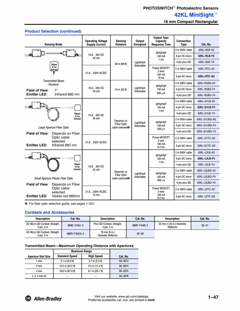
PHOTOSWITCHR Photoelectric Sensors
42KL MiniSightt18 mm Compact Rectangular
1--47Visit our website: www.ab.com/catalogs.Preferred availability cat. nos. are printed in bold.
Product Selection (continued)
Sensing ModeOperating VoltageSupply Current
SensingDistance
OutputEnergized
Output TypeCapacity
Response TimeConnection
Type Cat. No.
Objectto beSensed
Transmitted BeamReceiver
Field of View: 7_Emitter LED: Infrared 880 nm
10.8…30V DC25 mA
30 m (98 ft) Light/DarkSelectable
NPN/PNP100 mA1 ms
2 m 300V cable 42KL--RLB--A2
4-pin DC micro 42KL--RLB--F4
4-pin pico QD 42KL--RLB--Y4
21.6…250V AC/DC
Power MOSFET2-wire100 mA16 ms
2 m 300V cable 42KL--RTC--A2
3-pin AC micro 42KL--RTC--G3
10.8…30V DC25 mA 10 m (33 ft) Light/Dark
Selectable
NPN/PNP100 mA900 μs
2 m 300V cable 42KL--RLBQ--A2
4-pin DC micro 42KL--RLBQ--F4
4-pin pico QD 42KL--RLBQ--Y4
Objectto beSensed
Large Aperture Fiber Optic
Field of View: Depends on FiberOptic cableselected
Emitter LED: Infrared 880 nm
10.8…30V DC35 mA
Depends onFiber Optic
cable selected
Light/DarkSelectable
NPN/PNP100 mA1 ms
2 m 300V cable 42KL--G1LB--A2
4-pin DC micro 42KL--G1LB--F4
4-pin pico QD 42KL--G1LB--Y4
NPN/PNP100 mA300 μs
2 m 300V cable 42KL--G1LBQ--A2
4-pin DC micro 42KL--G1LBQ--F4
4-pin pico QD 42KL--G1LBQ--Y4
21.6…250V AC/DC
Power MOSFET2-wire100 mA8.3 ms
2 m 300V cable 42KL--G1TC--A2
3-pin AC micro 42KL--G1TC--G3
Objectto beSensed
Small Aperture Plastic Fiber Optic
Field of View: Depends on FiberOptic cableselected
Emitter LED: Visible red 660nm
10.8…30V DC35 mA
Depends onFiber Optic
cable selected
Light/DarkSelectable
NPN/PNP100 mA1 ms
2 m 300V cable 42KL--L2LB--A2
4-pin DC micro 42KL--L2LB--F4
4-pin pico QD 42KL--L2LB--Y4
NPN/PNP100 mA300 μs
2 m 300V cable 42KL--L2LBQ--A2
4-pin DC micro 42KL--L2LBQ--F4
4-pin pico QD 42KL--L2LBQ--Y4
21.6…250V AC/DC15 mA
Power MOSFET2-wire100 mA8.3 ms
2 m 300V cable 42KL--L2TC--A2
3-pin AC micro 42KL--L2TC--G3
For fiber optic selection guide, see pages 1--231.
Cordsets and Accessories
Description Cat. No. Description Cat. No. Description Cat. No.
DC Micro QD Cordset, Straight,4-pin, 2 m 889D--F4AC--2 Pico QD Cordset, Straight,
4-pin, 2 m 889P--F4AB--2 32 mm (1.25 in.) DiameterReflector 92--47
AC Micro QD Cordset, Straight,3-pin, 2 m 889R--F3AEA--2 76 mm (3 in.)
Diameter Reflector 92--39
Transmitted Beam—Maximum Operating Distance with Apertures
Aperture Slot Size
Maximum Range
Cat. No.Standard Speed High Speed
1 mm 2.1 m (6.9 ft) 0.7 m (2.3 ft) 60--2673
2 mm 10.5 m (34.5 ft) 3.5 m (11.4 ft) 60--2674
4 mm 18.6 m (61.0 ft) 6.1 m (20.1 ft) 60--2675
1, 2, 4 mm kit — — 60--2676

PHOTOSWITCHR Photoelectric Sensors
44R AccuSightt18 mm Right Angle
1--48 Visit our website: www.ab.com/catalogs.Preferred availability cat. nos. are printed in bold.
Features
S Narrow 27 mm deep housing
S 18 mm nose and through-holemounting options
S LED indicators with 360_ visibility
S No user adjustments required
S Multiple sensing modes
S Low voltage 24V DC operation
S Variety of connection types
SpecificationsEnvironmentalCertifications cULus and CE Marked for all applicable directives
Operating Environment NEMA 12, IP51
Operating Temperature [C (F)] 0…+50° (32…+122°)
Vibration 10…55 Hz, 1 mm amplitude, meets or exceeds IEC 60947--5--2
Shock 30 g with 1 ms pulse duration, meets or exceeds IEC 60947--5--2
Relative Humidity 5…95%
OpticalSensing Modes Diffuse, polarized retroreflective, wide angle, sharp cutoff
Sensing Range See Product Selection table on page 1--51
Field of View See Product Selection table on page 1--51
Light Source Visible red LED (660 nm), infrared LED (880 nm)
LED Indicators See User Interface below
Adjustments None
ElectricalVoltage 10…30V DC
Current Consumption 35 mA max
Sensor Protection Overload, short circuit, reverse polarity, false pulse
OutputsResponse Time 10 ms
Output Type PNP or NPN by cat. no., both PNP and NPN models
Output Mode Light or dark operate by cat. no.
Output Current 100 mA @ 30V DC max
Output Leakage Current 0.1 mA max
MechanicalHousing Material Valoxr
Lens Material Acrylic
Connection Types 2 m cable ( 24 AWG), 4-pin DC micro (M12) QD
Supplied Accessories 75012--097--01 18 mm locknut
Optional Accessories See mounting brackets, reflectors, and cordsets on page 1--51
User Interface
Label Color State
OFF
ON
OFF
ON
OFF
ON
Status
Sensor output de-activated
Sensor output activated
Margin < 1.2
Margin > 1.2
Sensor not powered
Sensor powered
Output Yellow
Margin Red
Power Green

PHOTOSWITCHR Photoelectric Sensors
44R AccuSightt18 mm Right Angle
1--49Visit our website: www.ab.com/catalogs.Preferred availability cat. nos. are printed in bold.
Wiring Diagrams
Models with Dual NPN and PNP Outputs
Models with NPN Outputs
Blue
Brown +
--
Models with PNP Outputs1
4
3
+
--
Brown
Blue
White
+
--
+
--
1
2
3
Black
Cable CableQuick-Disconnect Quick-Disconnect
Brown
Black
Blue
Brown
White
Blue
Brown
Blue
White
Black
+
--
+
--
1
24
3
Cable Quick-Disconnect
Brown
WhiteBlack
Blue
DC Micro
Load
Load
Load
Load
Load LoadLoad Load
DC Micro
32
41
32
41
All wire colors on quick-disconnect models refer to Rockwell Automation 889D cordsets.
Approximate Dimensions [mm (in.)]
28.6(1.12) 28.6
(1.12)
14.0(0.55)
12.0(0.47)
Wide Angle Diffuse ModelsPolarized Retroreflective andStandard Diffuse Models
26.4(1.04)
13.97(0.55)
2.4(0.09)
152.4(6.0)
14.48(0.57)
4-pin DCmicro QD or2 m (6.5 ft)cable
17.0(0.67)
Molded 18mm x 1--6gthreads onsnout
18 mm mounting nut(1 supplied per sensor)
35.0 (1.38)
38.1(1.5) 2.4
(0.09)
12.0(0.47) 1.57
(0.06)
152.4(6.0)
14.48(0.57)
4-pin DCmicro QD or2 m (6.5 ft)cable
38.1(1.5)
3.3(0.13)
Clearance for #6--32screw (2 places)
Models without 18 mmsnout
Clearance for #6--32screw (2 places)
35.0 (1.38)
Note: All sensors except wide angle diffuse models are supplied with one M18 mounting nut (Cat. No. 75012--097--01).

PHOTOSWITCHR Photoelectric Sensors
44R AccuSightt18 mm Right Angle
1--50 Visit our website: www.ab.com/catalogs.Preferred availability cat. nos. are printed in bold.
Typical Response CurvePolarized Retroreflective Sharp Cutoff Diffuse
Typical Response Curve
Standard Diffuse Wide Angle Diffuse
Operating Distance [m (ft)]
OperatingMargin
Operating Distance [m (ft)]
OperatingMargin
Operating Distance [mm (in.)]
OperatingMargin
Operating Distance [mm (in.)]
Beam
Width—in
Operating Distance [mm (in.)]
OperatingMargin
Operating Distance [mm (in.)]
Beam
Width—in
100
10
125.4(1.0)
254(10)
2.5m(8.3ft)
3.9m(13ft)
10(0.4)
100(4.0)
1(0)
100
10
1
254(10)
914(36)
25.4(1.0)
10
1
0.8
0.4
0
--0.4
--0.80 254
(10)508(20)
762(30)
1016(40)
254(10)
406(16)
25.4(1.0)
100
10
1127(5.0)
4
2
0
--2
--40 101.6
(4)203.2(8)
304.8(12)
406.4(16)
Beam Pattern Beam Pattern

PHOTOSWITCHR Photoelectric Sensors
44R AccuSightt18 mm Right Angle
1--51Visit our website: www.ab.com/catalogs.Preferred availability cat. nos. are printed in bold.
Product Selection
Sensing ModeOperating Voltage/
CurrentSensingDistance
OutputEnergized
Output Type/Capacity
Response TimeConnection
Type Cat. No.
Objectto beSensed
Polarized Retroreflective
Field of View: 1.5_Emitter LED: Visible red 660 nm
10…30V DC35 mA
25 mm…1.5 m(1 in…4.9 ft)
DarkOperate
NPN and PNP100 mA10 ms
2 m 300V cable 44RSP--2KBE1--A2
4-pin DC micro 44RSP--2KBE1--F4
25 mm…3 m(1 in…9.8 ft)
LightOperate
2 m 300V cable 44RSP--2JBE3--A2
4-pin DC micro 44RSP--2JBE3--F4
DarkOperate
2 m 300V cable 44RSP--2KBE3--A2
4-pin DC micro 44RSP--2KBE3--F4
LightOperate
NPN/100 mA10 ms
2 m 300V cable 44RSP--2JNE3--A2
4-pin DC micro 44RSP--2JNE3--F4
3-pin Molex 44RSP--2JNE3--Z6
PNP/100 mA10 ms
2 m 300V cable 44RSP--2JPE3--A2
4-pin DC micro 44RSP--2JPE3--F4
Objectto beSensed
Standard Diffuse
Field of View: 5_Emitter LED: Infrared 880 nm
10…30V DC35 mA
3…380 mm(0.12…15 in.)
LightOperate
NPN/100 mA10 ms
2 m 300V cable 44RSD--1JNC38--A2
4-pin DC micro 44RSD--1JNC38--F4
PNP/100 mA10 ms
2 m 300V cable 44RSD--1JPC38--A2
4-pin DC micro 44RSD--1JPC38--F4
Objectto beSensed
Sharp Cutoff Diffuse
Field of View: 5_Emitter LED: Infrared 880 nm
Background
10…30V DC35 mA
3…100 mm(0.12…4 in.)
LightOperate
NPN/100 mA10 ms
2 m 300V cable 44RSS--1JNB1--A2
4-pin DC micro 44RSS--1JNB1--F4
Objectto beSensed
Wide Angle Diffuse
Field of View: Approx. 60_Emitter LED: Infrared 880 nm
10…30V DC35 mA
3…200 mm(0.12…7.8 in.)
LightOperate
NPN/100 mA10 ms
2 m 300V cable 44RSW--1JNC20--A2
4-pin DC micro 44RSW--1JNC20--F4
PNP/100 mA10 ms
2 m 300V cable 44RSW--1JPC20--A2
4-pin DC micro 44RSW--1JPC20--F4
Cordsets and AccessoriesDescription Cat. No. Description Cat. No.
DC Micro QD Cordset, Straight, 4-pin, 2 m 889D--F4AC--2 Right Angle Mounting Bracket 60--2657
76 mm (3 in.) Diameter Reflector 92--39 Mounting Screws (not supplied) 2 x #6--32
32 mm (1.25 in.) Diameter Reflector 92--47

PHOTOSWITCHR Photoelectric Sensors
42CA18 mm Cylindrical
1--52 Visit our website: www.ab.com/catalogs.Preferred availability cat. nos. are printed in bold.
Description
The 42CA 18 mm cylindrical family ofgeneral purpose photoelectric sensorsis intended for light to medium dutyindustrial applications.
The 42CA family provides anindication if the sensor operation isunstable. An indicator flashes if thesignal level is too close to thedetection threshold. This helps foreasy alignment of the sensor andforewarns against detection of abackground.
Features
S 18 mm industry standard enclosure
S Extended range high--speedmodels
S Patented ASIC design offers linearsensitivity adjustment, stabilityindication and excellent noiseimmunity
S Two LED indicators provide statusof power, output, unstableoperation and short-circuitprotection
S Complementary light and dark
SpecificationsEnvironmentalCertifications cULus and CE Marked for all applicable directives
Operating Environment IP67
Operating Temperature [C (F)] --25…+70° (--13…+158°)
Vibration 10…55 Hz, 1 mm amplitude, meets or exceeds IEC 60947--5--2
Shock 30 g with 1 ms pulse duration, meets or exceeds IEC 60947--5--2
Relative Humidity 5…95% (noncondensing)
Ambient Light Immunity Incandescent light 5000 lux
OpticalSensing Modes Retroreflective, polarized retroreflective, diffuse, background suppression,
transmitted beam
Sensing Range See Product Selection table on page 1--55
Light Source Visible red LED (660 nm) or infrared LED (880 nm)
LED Indicators Green and yellow, see User Interface below
Adjustments Sensitivity potentiometer on select models
ElectricalVoltage 10…30V DC
Current Consumption 30 mA max
Sensor Protection Reverse polarity, overload, short circuit
OutputsResponse Time See Product Selection table on page 1--55
Output Type PNP or NPN by cat. no.
Output Mode Complementary light or dark operate, selectable light or dark operate forbackground suppression models
Output Current 100 mA
Output Leakage Current 10 μA max
MechanicalHousing Material PBT
Lens Material PMMA
Connection Types 2 m cable, 4-pin DC micro (M12) QD
Supplied Accessories 18 mm fastening nuts
Optional Accessories See mounting brackets, reflectors, and cordsets on page 1--56
User Interface Approximate Dimensions [mm (in.)]LEDColor State Status
16.5(0.65)Dia.
1.8(0.07)
66.5 (2.62)
LED
41.7 (1.64)17(0.67)
M18 x 1
SensitivityAdjustment
SensitivityAdjustment
M12 x 1 M18 x 116.5(0.65)Dia.
LED
9.7(0.38)
74.5 (2.93)41.7 (1.64) 1.8
(0.07)17
(0.67)Yellow
OFF Output de-energized
ON Output energized
Green
OFF Power is OFF
ON Power is ON
Flashing(6 Hertz)
Unstable (0.5 <Margin < 2)
Flashing(1.5 Hertz)
Output short-circuitprotection active
Black wire or pin 4 of connector.

PHOTOSWITCHR Photoelectric Sensors
42CA18 mm Cylindrical
1--53Visit our website: www.ab.com/catalogs.Preferred availability cat. nos. are printed in bold.
Wiring Diagrams
Black
Face View MaleReceptacle (Sensor)
DC Micro
Face View MaleReceptacle (Sensor)
DC Micro
Brown
Blue
White +
--
12
43
BrownWhite
BlackBlue
+
--
Cable Quick-Disconnect
Tie white (2) and brown (1) conductors together for L.O. Open circuit or tie white (2) and blue (3) conductors together for D.O.
NPN Output
Brown
Blue
WhiteBlack
+
--
12
4
3
BrownWhite
Black
Blue
+
--
Cable Quick-Disconnect
PNP Output
PNP Models with Complementary Outputs
Load
NPN Models with Complementary Outputs
Additional Wiring Options for Background Suppression and Transmitted Beam
Brown (1)
White (2)Black (4)
Blue (3)
LoadLoad
+
–
LODO
4
3
1
2
Brown (1)DO
Black (4)LoadLoad
+
–
LO
M12 MaleTransmitted Beam Emitter
Brown (1)
Black (2)
Blue (3)
+
–
Blue (3)
White (2)
Load
LoadLoad
Open circuit or tie white (2) and brown (1) conductors together for L.O. Tie white (2) and blue (3) conductors together for D.O.
For normal operation, black wire (pin 2) needs no connection. To disable light source, connect black wire (pin 2) to –V.
4
3
1
2
4
3
1
2
Typical Response Curves
Standard Diffuse [100 mm]
OperatingMargin
0 20(0.79)
100(3.9)
140(5.51)
100
1
0.1
10
Distance [mm (in.)]
60(2.36)
White Paper
Grey Paper18%
Background Suppression [50 mm] Background Suppression [100 mm]
OperatingMargin
0 1(0.04)
100(3.9)
100
1
10
Distance [mm (in.)]
10(0.39)
White Paper
Black Paper6% O
peratingMargin
0 10(0.39
Distance [mm (in.)]
100(3.94)
1(0.04
100
1
10
White Paper
BlackPaper 6%

PHOTOSWITCHR Photoelectric Sensors
42CA18 mm Cylindrical
1--54 Visit our website: www.ab.com/catalogs.Preferred availability cat. nos. are printed in bold.
Typical Response Curves (continued)Operating Margin
Retroreflective [4.8 m] Retroreflective [7.2 m] Polarized Retroreflective [3.8 m]
0.1(0.33)
10(32.8)
1(3.28)
OperatingMargin
100
1
10
Distance [m (ft)]
0.01(0.03)
with 92--124reflector
with 92--47reflector
0.1(0.33)
10(32.8)
1(3.28)
OperatingMargin
100
1
10
Distance [m (ft)]
1000
with 92--124reflector
with 92--47reflector
0.1(0.33)
10(32.8)
1(3.28)
OperatingMargin
100
1
10
Distance [m (ft)]
0.01(0.03)
with 92--124reflector
with 92--47reflector
Beam Pattern
Retroreflective [4.8 m] Retroreflective [7.2 m] Polarized Retroreflective [3.8 m]
1(3.3)
3(9.8)
2(6.56)
Beam
Diameter(mm)
40
80
60
Distance [m (ft)]
0 5(16.4)
4(13.1)
--20
20
0
--40
--80--60
2(6.56)
Beam
Diameter(mm)
40
80
60
Distance [m (ft)]
0 4(13.1)
6(19.7)
--20
20
0
--40
--80
--60
0 2(6.56)
3(9.8)
4(13.1)
1(3.3)
Distance [m (ft)]Beam
Diameter(mm)
40
60
--20
20
0
--40
--60
7.5(24.6)
Operating Margin
Standard Diffuse [400 mm] Standard Diffuse [1 m]
1(0.04)
100(3.9)
10(0.39)
1000(39.4)
OperatingMargin(X)
100
1
10
Distance [mm (in.)]
1(0.04)
100(3.9)
10(0.39)
10000(393.7)
1000(39.4)
OperatingMargin(X)
100
1
10
Distance [mm (in.)]
0.1(0.33)
10(32.8)
1(3.28)
OperatingMargin(X)
100
1
10
Distance [m (ft)]
1000
100(328)
Transmitted Beam [16 m]
Beam Pattern
Standard Diffuse [400 mm] Standard Diffuse [1 m] Transmitted Beam [16 m]
100(3.94)
Beam
Diameter(mm)
68
Distance [mm (in.)]
0 200(7.87)
300(11.8)
--2
4
0
--4
--6
400(15.7)
2
--8
200(7.87)
Beam
Diameter(m)
15
20
Distance [mm (in.)]
0 400(15.75)
600(23.6)
--5
10
0
--10
--15
800(31.5)
1000(39.4)
5
--20
4(13.1)
Beam
Diameter(m)
0.4
0.6
Distance [m (ft)]
0 8(26.2)
12(39.4)
--0.2
0.2
0
--0.4
--0.6
16(52.5)
20(65.6)

PHOTOSWITCHR Photoelectric Sensors
42CA18 mm Cylindrical
1--55Visit our website: www.ab.com/catalogs.Preferred availability cat. nos. are printed in bold.
Product Selection
Sensing Mode
OperatingVoltage
Supply CurrentSensingDistance
OutputEnergized
Output Type/ResponseTime
SensitivityAdjust Cat. No.
RetroreflectiveField of View: 1.2_Emitter LED: Visible red 660 nm
Objectto beSensed
10…30V DC25 mA max.
2 mm…4.8 m(0.08 in…15.7 ft)
Complementarylight and darkoperate
NPN100 mA1 ms
Noadjustment 42CA-U2MNB-D4
PNP100 mA1 ms
Noadjustment 42CA-U2MPB-D4
RetroreflectiveField of View: 1.2_Emitter LED: Visible red 660 nm
Objectto beSensed
10…30V DC25 mA max.
2 mm…7.2 m(0.08 in…23.6 ft)
Complementarylight and darkoperate
NPN100 mA0.5 ms
Single turnpotentiometer 42CA-U2MNA-D4
PNP100 mA0.5 ms
Single turnpotentiometer 42CA-U2MPA-D4
Polarized Retroreflective
Field of View: 1.3_Emitter LED: Visible red 660 nm
Objectto beSensed
10…30V DC25 mA max.
2 mm…3.8 m(0.08 in…12.5 ft)
Complementarylight and darkoperate
NPN100 mA1 ms
Noadjustment 42CA-P2MNB-D4
PNP100 mA1 ms
Noadjustment 42CA-P2MPB-D4
Standard DiffuseField of View: 3_Emitter LED: Infrared 880 nm
Objectto beSensed
10…30V DC30 mA max.
0…100 mm(0…3.94 in.)
Complementarylight and darkoperate
NPN100 mA1 ms
Single turnpotentiometer 42CA-D1MNAE-D4
PNP100 mA1 ms
Single turnpotentiometer 42CA-D1MPAE-D4
Standard DiffuseField of View: 7.5_Emitter LED: Infrared 880 nm
Objectto beSensed
10…30V DC25 mA max.
0…400 mm(0…15.7 in.)
Complementarylight and darkoperate
NPN100 mA1 ms
Single turnpotentiometer 42CA-D1MNAJ-D4
PNP100 mA1 ms
Single turnpotentiometer 42CA-D1MPAJ-D4
Standard DiffuseField of View: 5_Emitter LED: Infrared 880 nm
Objectto beSensed
10…30V DC30 mA max.
0…1000 mm(0…39.4 in.)
Complementarylight and darkoperate
NPN100 mA0.5 ms
Single turnpotentiometer 42CA-D1MNAL-D4
PNP100 mA0.5 ms
Single turnpotentiometer 42CA-D1MPAL-D4
Suffix --D4 denotes 4-pin DC micro connection type. For 2 m cable without QD replace suffix --D4 with --A2 (e.g. 42CA--P2MPB--A2).Refer to www.ab.com/sensors for updated information.
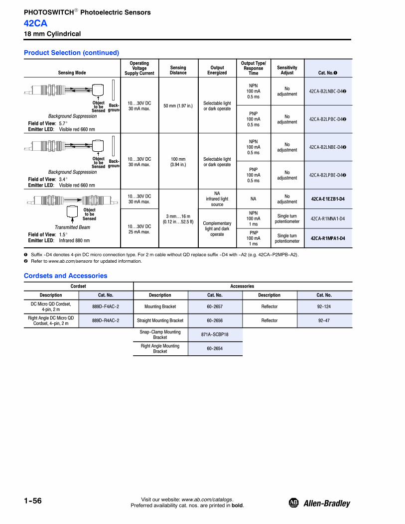
PHOTOSWITCHR Photoelectric Sensors
42CA18 mm Cylindrical
1--56 Visit our website: www.ab.com/catalogs.Preferred availability cat. nos. are printed in bold.
Product Selection (continued)
Sensing Mode
OperatingVoltage
Supply CurrentSensingDistance
OutputEnergized
Output Type/ResponseTime
SensitivityAdjust Cat. No.
Background SuppressionField of View: 5.7_Emitter LED: Visible red 660 nm
Objectto beSensed
Back-ground
10…30V DC30 mA max. 50 mm (1.97 in.) Selectable light
or dark operate
NPN100 mA0.5 ms
Noadjustment 42CA-B2LNBC-D4
PNP100 mA0.5 ms
Noadjustment 42CA-B2LPBC-D4
Background SuppressionField of View: 3.4_Emitter LED: Visible red 660 nm
Objectto beSensed
Back-ground
10…30V DC30 mA max.
100 mm(3.94 in.)
Selectable lightor dark operate
NPN100 mA0.5 ms
Noadjustment 42CA-B2LNBE-D4
PNP100 mA0.5 ms
Noadjustment 42CA-B2LPBE-D4
Transmitted BeamField of View: 1.5_Emitter LED: Infrared 880 nm
Objectto beSensed
10…30V DC30 mA max.
3 mm…16 m(0.12 in…52.5 ft)
NAinfrared lightsource
NA Noadjustment 42CA-E1EZB1-D4
10…30V DC25 mA max.
Complementarylight and darkoperate
NPN100 mA1 ms
Single turnpotentiometer 42CA-R1MNA1-D4
PNP100 mA1 ms
Single turnpotentiometer 42CA-R1MPA1-D4
Suffix --D4 denotes 4-pin DC micro connection type. For 2 m cable without QD replace suffix --D4 with --A2 (e.g. 42CA--P2MPB--A2).Refer to www.ab.com/sensors for updated information.
Cordsets and AccessoriesCordset Accessories
Description Cat. No. Description Cat. No. Description Cat. No.
DC Micro QD Cordset,4-pin, 2 m 889D--F4AC--2 Mounting Bracket 60--2657 Reflector 92--124
Right Angle DC Micro QDCordset, 4--pin, 2 m 889D--R4AC--2 Straight Mounting Bracket 60--2656 Reflector 92--47
Snap--Clamp MountingBracket 871A--SCBP18
Right Angle MountingBracket 60--2654

PHOTOSWITCH Photoelectric Sensors
42CS CylindricalFood and Beverage
1Visit our website: www.ab.com/catalogs.Preferred availability cat. nos. are printed in bold. New
Description
The 42CS family of sensors offers awide range of sensing modes in asmooth 316L stainless steel housing,ideal for food, beverage andpharmaceutical applications.
The innovative ferromagnetic teachfeature makes the sensor easy tosetup by simply placing aferromagnetic metal object on asection of the sensor’s housing toinitiate the teach process. Its smoothand clean design minimizes thecollection and accumulation ofundesired particles allowing for a fastand easy clean up. There are also18 mm threaded models available.
Features
Patented ferromagnetic teach foreasy sensor programming
Smooth barrel design minimizesthe accumulation of undesiredparticles and allows for fast andeasy clean up.
Specifications
Certifications cULus and CE marked for all applicable directives
Environmental
Operating Environment IP69K rated, ECOLAB and Johnson Diversey certified
Operating Temperature [C (F)] --25…+85° (--13…185°)
Vibration 10…55Hz, 1 mm amplitude; meets or exceeds IEC 60947--5--2
Shock 30 g with 11 ms pulse duration, meets or exceeds IEC 60947--5--2
Relative Humidity 5…95% (noncondensing)
Ambient Light Immunity 5000 Lux (Incandescent light) and 100000 Lux (Sunlight)
Optical
Sensing Modes Diffuse, background suppression, polarized retroreflective, clear object,and transmitted beam
Sensing Range See product selection table
Light Source Visible red (660 nm) or infrared (880 nm)
LED indicators See user interface
Sensitivity Adjustments Ferromagnetic teach
Electrical
Voltage 10…30V DC
Current Consumption 35 mA max
Sensor Protection Short circuit, transient noise, reverse polarity and overload
Outputs
Response Time 1 ms (diffuse, polarized retroreflectived, clear object),1.25 ms (background suppression),2 ms (transmitted beam)
Output Type PNP or NPN by cat. no.
Output Mode Complementary light and dark operate
Output Current 100 mA
Output Leakage Current 10 µA max.
Mechanical
Housing Material Stainless steel 316L
Lens Material PMMA
Connector Material PPS (grilamid)
Connection Types 4-pin DC micro (M12) QD
Supplied Accessories Stainless steel teach rod, mounting nuts (threaded models only)
Optional Accessories Mounting brackets, cordsets, reflectors
Extended temperature operatingrange
18 mm stainless steel 316Lenclosure with laser etchedmarkings
Background suppression modelsfor improved detection of shinyobjects
Two teach modes: standard andprecision
Teach lockout feature preventsunauthorized users from changingthe settings
Input to disable light source ontransmitted beam emitter
IP69K, ECOLAB and JohnsonDiversey rated
User Interface
LED Status
Green
OFF Teach function is locked
ON Teach function is enabled
Flashing (8 Hz) Short Circuit
YellowOFF Output de-energized
ON Output energized
Flashing (3 Hz) Output energized (Margin < 2)
Pin 4 of Micro (M12) QD. L.O for diffuse, background suppression. D.O for polarized retroreflective and transmittedbeam
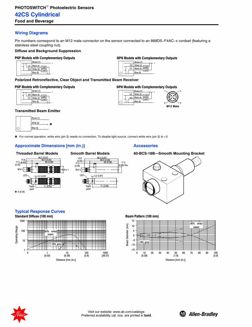
PHOTOSWITCH Photoelectric Sensors
42CS CylindricalFood and Beverage
2 Visit our website: www.ab.com/catalogs.Preferred availability cat. nos. are printed in bold.New
Wiring Diagrams
Pin numbers correspond to an M12 male connector on the sensor connected to an 889DS--F4AC--x cordset (featuring astainless steel coupling nut).
Diffuse and Background Suppression
Brown (1)
White (2)
Black (4)
Blue (3)
Load
Load
+
–
LO
DO
PNP Models with Complementary Outputs NPN Models with Complementary OutputsBrown (1)
White (2)DO
Black (4)
Blue (3)
Load
Load
+
–
LO
Polarized Retroreflective, Clear Object and Transmitted Beam Receiver
Brown (1)
White (2)
Black (4)
Blue (3)
Load
Load
+
–
LO
DO
PNP Models with Complementary Outputs NPN Models with Complementary OutputsBrown (1)
White (2)
DO Black (4)
Blue (3)
Load
Load
+
–
LO
4
3
1
2
M12 Male
Transmitted Beam Emitter
Brown (1)
White (2)
Blue (3)
+
–
For normal operation, white wire (pin 2) needs no connection. To disable light source, connect white wire (pin 2) to +V.
Approximate Dimensions [mm (in.)] Accessories
98.3 (3.87)
17.5(0.69) Dia.
15.8(0.63)
11.5(0.45)
65 (2.56)82.5 (3.25)
M12 x 1 M18 x 1
15.8(0.63)11.5
(0.45)
6 (0.24)
M12 x 1
LED
71 (2.80)
2.2 (0.87)LED
98.3 (3.87)
65 (2.56)82.5 (3.25)
71 (2.80)
2.2 (0.87)
60-BCS-18B—Smooth Mounting BracketThreaded Barrel Models Smooth Barrel Models
Teachpoint
Teachpoint
Typical Response Curves
10 100(0.39) (3.9)
0 20 30 40 50 60 70 80 90
BeamDiameter(mm)
Standard Diffuse (100 mm)
1
10
100
1000
0 1 10 100 1000
Distance [mm (in.)]
OperatingMargin
90% whitepaper
--15
--5
5
15
--10
0
10
Distance [mm (in.)]
Beam Pattern (100 mm)
90% white
paper
(0.03) (0.39) (3.9) (39.37) (1.9)
18% grey18% grey

PHOTOSWITCH Photoelectric Sensors
42CS CylindricalFood and Beverage
3Visit our website: www.ab.com/catalogs.Preferred availability cat. nos. are printed in bold. New
1
10
100
1000
Distance [mm (in.)]
OperatingMargin
Standard Diffuse (400 mm) Beam Pattern (400 mm)
0 50 100 150 200 250 300 350 400
BeamDiameter(mm)
--30
--10
10
30
--20
0
20
Distance [mm (in.)]
90% white
paper
18% grey
0 1 10 100 1000(0.03) (0.39) (3.9) (39.37) (1.9) (3.8) (5.9) (7.8) (9.8) (11.8) (13.7) (15.7)
90% white
paper
18% grey
1
10
1000
Distance [mm (in.)]
OperatingMargin
BeamDiameter(mm)
Distance [mm (in.)]
0 100 200 300 400 500 600 700 800
--100
100
200
--200
0
700 800
Standard Diffuse (800 mm) Beam Pattern (800 mm)
0 1 10 100 1000(0.03) (0.39) (3.9) (39.37) (3.8) (19.6) (31.5)
90% white
paper
18% grey
1(3.28
Polarized Retroreflective (4 m)
0 10 20 30 40
Distance [m (ft)]
Beam Pattern (4 m)
1
10
100
OperatingMargin
Clear Object (1 m) Beam Pattern (1 m)
BeamDiameter(mm)
--150
100
200
--250
0
Transmitted Beam (20 m) Beam Pattern (20 m)
1
10
100
0.01 0.10 1.00 10.00
Distance [m (ft)]
OperatingMargin
92--39
92--47
BeamDiameter(mm)
--50
2030
50
100
40
--20--30
--10
--40
Distance [m (ft)] Distance [m (ft)]
BeamDiameter(mm)
1
10
1000
OperatingMargin
10000
100
0
Distance [m (ft)] Distance [m (ft)]
250
150
50
--50--100
--200
(0.03) (0.32) (3.28) (32.8) (32.8) (65.6) (98.4) (131.2)
0.01 0.10 1.00 10.00(0.03) (0.32) (3.28) (32.8)
0 2(6.56)
0 1 10 100(0.03) (0.39) (3.9)
0 10 20 30(32.8) (65.6) (98.4)
5(16.4)
15(49.2)
25(82)
--50
2030
50
100
40
--20--30
--10
--40

PHOTOSWITCH Photoelectric Sensors
42CS CylindricalFood and Beverage
4 Visit our website: www.ab.com/catalogs.Preferred availability cat. nos. are printed in bold.New
Product Selection
Sensing Mode(max. range)
SensingDistance
OutputEnergized
Output TypeCapacity
SensitivityAdjustment Cat. No.
Polarized Retroreflective
Field of View: 3°
Emitter LED: Visible red 660 nm
Objectto besensed
4 m (13.1 ft)
Complementarylight and dark
operate
NPN
No adjustment
42CSS--P2MNB1--D4
PNP 42CSS- P2MPB1- D4
Clear Object Detection
Field of View: 3°
Emitter LED: Visible red 660 nm
Objectto besensed
1 m (3.2 ft)
Complementarylight and dark
operate
NPN
FerromagneticTeach
42CSS--C2MNA1--D4
PNP 42CSS- C2MPA1- D4
Standard Diffuse
Field of View: 6° for 100 and 400 mm8° for 800 mm
Emitter LED: Visible red 660 nm
Objectto besensed
100 mm (3.9 in.)
Complementarylight and dark
operate
NPNFerromagnetic
Teach
42CSS--D2MNA1--D4
PNP 42CSS- D2MPA1- D4
400 mm (15.8 in.)
Complementarylight and dark
operate
NPNFerromagnetic
Teach
42CSS--D1MNA2--D4
PNP 42CSS- D1MPA2- D4
800 mm (31.5 in.)
Complementarylight and dark
operate
NPNFerromagnetic
Teach
42CSS--D1MPNA3--D4
PNP 42CSS- D1MPA3- D4
Background Suppression
Field of View: 9°
Emitter LED: Visible red 660 nm
Objectto besensed back--
ground
60…100 mm(2.4…3.9 in.)
Complementarylight and dark
operate
NPN
FerromagneticTeach
42CSS--B2MNA1--D4
PNP 42CSS- B2MPA1- D4
Transmitted Beam
Field of View: 4°
Emitter LED: Infrared 880 nm
Object tobe sensed
20 m (65.6 ft)
NALight Source
NA
No adjustment
42CSS- E1EZB1- D4
Complementarylight and dark
operate
NPN 42CSS--R9MNB1--D4
PNP 42CSS- R9MPB1- D4
Note: All sensor models are rated for 10…30V DC and can drive loads requiring up to 100 mA.
The prefix 42CSS denotes smooth enclosure. For threaded models replace the 42CSS with 42CST (e.g., 42CST--P2MPB1--D4).
Cordsets and Accessories
Cordset/Patchcords Accessories
Description Cat. No. Description Cat. No. Description Cat. No. Description Cat. No.
DC Micro (M12) QDCordset, 4-pin
889DS--F4AC--Block Mounting Bracket
for Smooth BarrelHousing
60--BCS--18BRight Angle MountingBracket for Threaded
Models60--2657
Reflector, 76 mm (3 in.)dia. with center mount hole
92--39
DC Micro (M12) QDPatchcord, 4-pin
889D--F4ACDM--Straight Mounting Bracketfor Threaded Models
60--2656Stainless Steel Right
Angle Mounting Bracket871A--BRS18
Reflector, 32 mm (1.5 in.)dia.
92--47
Reflector, 76 mm (3 in.)dia. for clear object sensors
92--90
Replace symbol with 2 (2 m), 5 (5 m), or 10 (10 m) for standard cable lengths. Replace symbol with 0M3 (1 ft), 1 (1 m) 2 (2 m), 5 (5 m), or 10 (10 m) for standard cable lengths.

PHOTOSWITCHR Photoelectric Sensors
42CM18 mm Metal Cylindrical
1--57Visit our website: www.ab.com/catalogs.Preferred availability cat. nos. are printed in bold.
Features
S 18 mm industry standard package
S Wide selection of sensing modes
S 30V DC operation
S NPN or PNP outputs
S Fast response time
S Variety of connection types
S Laser models available(see page 1--115)
SpecificationsEnvironmentalCertifications cULus and CE Marked for all applicable directives
Operating Environment IP67
Operating Temperature [C (F)] --25…+70° (--13…+158°)
Vibration 10…55 Hz, 1 mm amplitude, meets or exceeds IEC 60068--2--6
Shock 30 g with 1 ms pulse duration, meets or exceeds IEC 60068--2--27
Relative Humidity 5…95%
Ambient Light Immunity Incandescent light 3000 lux
Optical
Sensing Modes Retroreflective, polarized retroreflective, diffuse, backgroundsuppression, transmitted beam
Sensing Range See Product Selection table on page 1--60
Field of View See Product Selection table on page 1--60
Light Source Visible red LED (660 nm) or infrared LED (880 nm)
LED Indicators Yellow LED for output indication
Adjustments Sensitivity potentiometer (diffuse models only)
Electrical
Voltage 10…30V DC
Current Consumption 30 mA max
Sensor Protection Reverse polarity, overload, short circuit
Outputs
Response Time 2 ms (0.5 ms for background suppression)
Output Type PNP or NPN by cat. no.
Output Mode Complementary light operate or dark operate, selectable light operateor dark operate for background suppression models
Output Current 100 mA
Output Leakage Current 10 μA max
Mechanical
Housing Material Nickel-plated brass
Lens Material PMMA/PC
Connection Types 2 m cable, 4-pin DC micro (M12) QD
Supplied Accessories 18 mm fastening nuts
Optional Accessories See mounting brackets, reflectors, and cordsets on page 1--61
User Interface Panel
Label Color State Status
11 (0.43)
LED
Sensitivity Adjustment (Diffuse models only)
Output YellowOFF Sensor output de-activated
ON Sensor output activated

PHOTOSWITCHR Photoelectric Sensors
42CM18 mm Metal Cylindrical
1--58 Visit our website: www.ab.com/catalogs.Preferred availability cat. nos. are printed in bold.
Wiring Diagrams
Black
White
Face View MaleReceptacle (Sensor)
DC Micro
Brown
Blue
White
Black
+
--
1
2
4
3
Brown
White
Black
Blue
+
--
Cable Quick-DisconnectNPN Output
Brown
Blue
White
Black
+
--
1
2
4
3
LOBrown
DO
Blue
+
--
Cable
Load
Quick-Disconnect
Load
LO
DOLoad
Load Load
LO
DOLoad
Load
LO
DOLoad
Quick-DisconnectPNP Output
White
DiffuseFace View Male
Receptacle (Sensor)DC Micro
Blue
Brown +
--
1
3
+
--
Brown
Blue
Cable Quick-Disconnect
Brown
Blue
White
Black
+
--
1
2
4
3
Brown
White
Black
Blue
+
--
Cable Quick-DisconnectNPN Output
Brown
Blue
White
Black
+
--
1
2
4
3
Brown
Black
Blue
+
--
Cable Quick-DisconnectPNP Output
Transmitted Beam, Retroreflective, Polarized Retroreflective
LO
DOLoad
LoadLO
DOLoad
LoadLO
DOLoad
LoadLO
DOLoad
Load
43
1
2
32
41
Black
Background Suppression
White
Face View MaleReceptacle (Sensor)
DC Micro
Brown
Blue
White
Black
+
--
1
2
4
3
Brown
White
Black
Blue
+
--
Cable Quick-DisconnectNPN Output
Brown
Blue
White
Black
+
--
1
2
4
3
Brown
Blue
+
--
Cable Quick-Disconnect
Load Load Load Load
Quick-DisconnectPNP Output
43
1
2
Open circuit or tie white (2) and brown (1) conductors together for L.O. Tie white (2) and blue (3) conductors together for D.O.Tie white (2) and brown (1) conductors together for L.O. or tie white (2) and blue (3) conductors together for D.O.
Approximate Dimensions [mm (in.)]
M12 x 1
2.3(0.09)
1.2(0.04) 17.6
(0.69)15.6(0.61)
16.4(0.64)Dia.
3(0.11)
79.4 (3.12)
42.5 (1.67)17.6(0.69)
M18 x 1
42.5 (1.67) 3.7(0.14)
M18 x 1
LED

PHOTOSWITCHR Photoelectric Sensors
42CM18 mm Metal Cylindrical
1--59Visit our website: www.ab.com/catalogs.Preferred availability cat. nos. are printed in bold.
Typical Response Curve
0 1(0.04)
100(3.9)
100
1
10
10(0.39)
White Paper
Black Paper6%
Retroreflective Polarized Retroreflective
Distance [m (ft)]
OperatingMargin
OperatingMargin
Distance [mm (in.)]Distance [m (ft)]
Background Suppression50 mm
Transmitted Beam
OperatingMargin
Distance [mm (in.)] Distance [mm (in.)] Distance [m (ft)]
OperatingMargin
100
1
0.1
0 2(6.5)
4(13)
10
6(19.7)
10
10 1
(3.2)2
(6.5)3
(9.8)4(13)
0
100
1
0.1
10
80(3.15)
40(1.57)
120(4.72)
White Paper
Grey Paper18%
Standard Diffuse100 mm
Standard Diffuse400 mm
OperatingMargin
OperatingMargin
0 300(11.81)
400(15.75)
500(19.69)
100
1
10
100(3.94)
200(7.87)
White Paper
Grey Paper18%
Distance [mm (in.)]
Background Suppression100 mm
0 10(0.39
100(3.94)
1(0.04
100
1
10
White Paper
Black Paper6%
OperatingMargin
1000
1
100
0 4(13.1)
16(52.5)
8(26.2)
12(39.3)
20(65.6)
10

PHOTOSWITCHR Photoelectric Sensors
42CM18 mm Metal Cylindrical
1--60 Visit our website: www.ab.com/catalogs.Preferred availability cat. nos. are printed in bold.
Product Selection
Sensing ModeOperating VoltageSupply Current
SensingDistance
@ 1X MarginOutput
Energized
Output TypeCapacity
Response TimeConnection
Type Cat. No.
Objectto beSensed
Retroreflective
Field of View: 1.9_Emitter LED: Infrared 880 nm
10…30V DC30 mA
3 mm…4 m(0.12 in…13.2 ft)
LO/DOComplemen-
tary
NPN100 mA4 ms
2 m 300V cable 42CM--U1MNB--A2
4-pin DC micro 42CM--U1MNB--D4
PNP100 mA4 ms
2 m 300V cable 42CM--U1MPB--A2
4-pin DC micro 42CM--U1MPB--D4
Objectto beSensed
Polarized Retroreflective
Field of View: 1.8_Emitter LED: Visible red 660 nm
10…30V DC30 mA
3 mm…3 m(0.12 in…9.9 ft)
LO/DOComplemen-
tary
NPN100 mA4 ms
2 m 300V cable 42CM--P2MNB--A2
4-pin DC micro 42CM--P2MNB--D4
PNP100 mA4 ms
2 m 300V cable 42CM--P2MPB--A2
4-pin DC micro 42CM--P2MPB--D4
Objectto beSensed
Standard Diffuse
Field of View: 6.6_Emitter LED: Visible Red 660 nm 10…30V DC
30 mA
100 mm(3.9 in.)
(Adjustable)
LO/DOComplemen-
tary
NPN100 mA2 ms
2 m 300V cable 42CM--D2MNAE--A2
4-pin DC micro 42CM--D2MNAE--D4
PNP100 mA2 ms
2 m 300V cable 42CM--D2MPAE--A2
4-pin DC micro 42CM--D2MPAE--D4
Objectto beSensed
Standard Diffuse
Field of View: 6.6_Emitter LED: Infrared 880 nm
400 mm(13.6 in.)(Adjustable)
LO/DOComplemen-
tary
NPN100 mA2 ms
2 m 300V cable 42CM--D1MNAL--A2
4-pin DC micro 42CM--D1MNAL--D4
PNP100 mA2 ms
2 m 300V cable 42CM--D1MPAL--A2
4-pin DC micro 42CM--D1MPAL--D4
Objectto beSensed
Background Suppression
Field of View: 50 mm = 5.7_100 mm = 3.4_
Emitter LED: Visible red 660 nm
10…30V DC30 mA
50 mm (1.97 in.)
L.O./D.O.Selectable
NPN100 mA0.5 ms
2 m 300V cable 42CM--B2LNBC--A2
4-pin DC micro 42CM--B2LNBC--D4
PNP100 mA0.5 ms
2 m 300V cable 42CM--B2LPBC--A2
4-pin DC micro 42CM--B2LPBC--D4
100 mm (3.9 in.)
NPN100 mA0.5 ms
2 m 300V cable 42CM--B2LNBE--A2
4-pin DC micro 42CM--B2LNBE--D4
PNP100 mA0.5 ms
2 m 300V cable 42CM--B2LPBE--A2
4-pin DC micro 42CM--B2LPBE--D4
Refer to page 1--61 for cordsets and accessories.

PHOTOSWITCHR Photoelectric Sensors
42CM18 mm Metal Cylindrical
1--61Visit our website: www.ab.com/catalogs.Preferred availability cat. nos. are printed in bold.
Product Selection (continued)
Sensing ModeOperating VoltageSupply Current
SensingDistance
OutputEnergized
Output TypeCapacity
Response TimeConnection
Type Cat. No.
Objectto beSensed
Transmitted Beam
Field of View: 1.6_Emitter LED: Infrared 880 nm
10…30V DC25 mA
3 mm…20 m(0.12 in…65.6 ft)
NALight Source
2 m 300V cable 42CM--E1EZB--A2
4-pin DC micro 42CM--E1EZB--D4
L.O./D.O.Complemen-
tary
NPN100 mA2 ms
2 m 300V cable 42CM--R1MNB--A2
4-pin DC micro 42CM--R1MNB--D4
PNP100 mA2 ms
2 m 300V cable 42CM--R1MPB--A2
4-pin DC micro 42CM--R1MPB--D4
Cordsets and Accessories
Cordset Accessories
Description Cat. No. Description Cat. No. Description Cat. No.
DC Micro QD Cordset,4-pin, 2 m 889D--F4AC--2 Mounting Brackets 60--2657 Reflectors 92--39
DC Micro QD Cordset,4-pin, 2 m 889D--F4AC--2 Mounting Brackets 60--2649 Mounting Brackets 60--2664
Snap--Clamp MountingBrackets 871A--SCBP18

PHOTOSWITCHR Photoelectric Sensors
42CF12 mm Metal Cylindrical
1--62 Visit our website: www.ab.com/catalogs.Preferred availability cat. nos. are printed in bold.
Features
S 12 mm industry standard package
S Wide selection of sensing modes
S 30V DC operation
S NPN or PNP outputs
S Fast response time
S Variety of connection types
S Local teach button
S Accepts remote (diffuse andpolarized retroreflective only) teachinput
SpecificationsEnvironmentalCertifications cULus and CE Marked for all applicable directives
Operating Environment IP67
Operating Temperature [C (F)] --25…+70° (--13…+158°)
Vibration 10…55 Hz, 1 mm amplitude, meets or exceeds IEC 60068--2--6
Shock 30 g with 1 ms pulse duration, meets or exceeds IEC 60068--2--27
Relative Humidity 5....95%
Ambient Light Immunity Incandescent light 3000 lux
Optical
Sensing Modes Polarized retroreflective, standard diffuse, transmitted beam
Sensing Range See Product Selection table on page 1--64
Field of View See Product Selection table on page 1--64
Light Source Visible red LED (660 nm) or infrared LED (880 nm)
LED Indicators Yellow LED for output indication
Adjustments Sensitivity potentiometer
Electrical
Voltage 10…30V DC
Current Consumption 30 mA max
Sensor Protection Reverse polarity, overload, short circuit
Outputs
Response Time 2 ms (transmitted beam), 1.25 ms (diffuse and polarized retroreflective)
Output Type PNP or NPN by cat. no.
Output Mode Selectable light operate or dark operate
Output Current 100 mA
Output Leakage Current 10 μA max
Mechanical
Housing Material Nickel plated brass
Lens Material Acrylic
Connection Types 2 m cable, 4-pin DC micro (M12) QD
Optional Accessories See mounting brackets, reflectors, and cordsets on page 1--64
User Interface Panel
Label Color State Status54.5 (2.14) 4.0 (0.15)
4.4(0.17)
12.3(0.48)
3.75 (0.14)Dia.
Sensitivity Adjustment
LED
Output YellowOFF Sensor output de-activated
ON Sensor output activated

PHOTOSWITCHR Photoelectric Sensors
42CF12 mm Metal Cylindrical
1--63Visit our website: www.ab.com/catalogs.Preferred availability cat. nos. are printed in bold.
Wiring Diagrams
43
1
2
Blue
Brown +
--
1
3
+
--
Brown
Blue
Diffuse, Polarized Retroreflective and Transmitted Beam
Brown
Blue
WhiteBlack
+
--
124
3
Brown
WhiteBlack
Blue
+
--
Cable Quick-Disconnect Face View Male Receptacle(Sensor) DC Micro
Cable Quick-DisconnectNPN Output
Brown
Blue
WhiteBlack
+
--
1
24
3
Brown
WhiteBlack
Blue
+
--
Cable Quick-DisconnectPNP Output
Load Load Load Load
Face View Male Receptacle(Sensor) DC Micro
43
1
2
Polarized retroreflective: Open circuit for dark operate. Connect white (2) and brown (1) together for light operate. Connect white (2) and blue (3) togetherfor remote teach.Diffuse: Open circuit for light operate. Connect white (2) and brown (1) together for dark operate. Connect white (2) and blue (3) together for remote teach.Transmitted beam: Open circuit for dark operate. Connect white (2) and brown (1) together for light operate. Connect white (2) and blue (3) together for darkoperate. This model does not have remote teach.
Approximate Dimensions [mm (in.)]
M12 x 1M12 x 1
2.5(0.09)
55 (2.16)
34 (1.33) 17.7 (0.69) 0.8 (0.03)
4.0 (0.15)
54.5 (2.14) 4.0 (0.15)4.4(0.17)
12.3(0.48)
3.75 (0.14)Dia.
2.5(0.09)
66 (2.60)
34 (1.33) 22 (0.86) 1.0 (0.04)6.5(0.25)
65.5 (2.57)
1.0 (0.04)4.4(0.17)
22.3(0.87)
2.0(0.07)
Diffuse and Polarized Retroreflective
Transmitted Beam
Sensitivity Adjustment
LED
Typical Response CurvePolarized Retroreflective Standard Diffuse
100 mmTransmitted Beam
Distance [m (ft)]
OperatingMargin
OperatingMargin
Distance [m (ft)]
OperatingMargin
Distance [mm (in.)]
10
1
0 1(3.2)
2(6.5)
0.5(1.6)
2.5(8.2)
1000
100
1.5(4.9)
0 20(0.78)
100(3.9)
100
1
10
80(3.15)
60(2.36)
40(1.57)
120(4.72)
1000
White Paper
Black Paper6%
Standard Diffuse300 mm
0 300(11.81)
100(3.94)
200(7.87)
100
1
10
1000
White Paper
Black Paper6%
OperatingMargin
Distance [mm (in.)]
1000
1
100
0
10
2(6.6)
5(16.4)
3(9.8)
1(3.3)
4(13)

PHOTOSWITCHR Photoelectric Sensors
42CF12 mm Metal Cylindrical
1--64 Visit our website: www.ab.com/catalogs.Preferred availability cat. nos. are printed in bold.
Product Selection
Sensing ModeOperating VoltageSupply Current
SensingDistance
@ 1X MarginOutput
Energized
Output TypeCapacity
Response TimeConnection
Type Cat. No.
Objectto beSensed
Polarized Retroreflective
Field of View: 2.3_Emitter LED: Visible red 660 nm
10…30V DC30 mA
3 mm…2 m(0.12 in…6.5 ft)
L.O./D.O.Selectable
NPN100 mA1.25 ms
2 m 300V cable 42CF--P2LNA1--A2
4-pin DC micro 42CF--P2LNA1--D4
PNP100 mA1.25 ms
2 m 300V cable 42CF--P2LPA1--A2
4-pin DC micro 42CF--P2LPA1--D4
Objectto beSensed
Standard Diffuse
Field of View: 11.4_ (100 mm)5.3_ (300 mm)
Emitter LED: Infrared 880 nm
10…30V DC30 mA
0…100 mm(0…3.9 in.)(adjustable)
L.O./D.O.Selectable
NPN100 mA1.25 ms
2 m 300V cable 42CF--D1LNA1--A2
4-pin DC micro 42CF--D1LNA1--D4
PNP100 mA1.25 ms
2 m 300V cable 42CF--D1LPA1--A2
4-pin DC micro 42CF--D1LPA1--D4
0…300 mm(0…12.2 in.)(adjustable)
NPN100 mA1.25 ms
2 m 300V cable 42CF--D1LNA2--A2
4-pin DC micro 42CF--D1LNA2--D4
PNP100 mA1.25 ms
2 m 300V cable 42CF--D1LPA2--A2
4-pin DC micro 42CF--D1LPA2--D4
Objectto beSensed
Transmitted Beam
Field of View: 1.4_Emitter LED: Infrared 880 nm
10…30V DC25 mA
3 mm…4 m(0.12 in…13.2 ft)
—2 m 300V cable 42CF--E1EZB--A2
4-pin DC micro 42CF--E1EZB--D4
10…30V DC20 mA
L.O./D.O.Selectable
NPN100 mA2 ms
2 m 300V cable 42CF--R1LNB1--A2
4-pin DC micro 42CF--R1LNB1--D4
PNP100 mA2 ms
2 m 300V cable 42CF--R1LPB1--A2
4-pin DC micro 42CF--R1LPB1--D4
Cordsets and Accessories
Cordset Accessories
Description Cat. No. Description Cat. No. Description Cat. No.
DC Micro QD Cordset,4-pin, 2 m 889D--F4AC--2 Mounting Bracket 871A--BRNR Reflectors 92--39
Snap--Clamp MountingBracket 871A--SCBP12

PHOTOSWITCHR Photoelectric Sensors
Series 9000Standard and Timing
1--65Visit our website: www.ab.com/catalogs.Preferred availability cat. nos. are printed in bold.
FeaturesS Wide selection of sensing modes
S Wide selection of operating modesS Both DC and AC/DC operation
S Models with teach functionS Standard ON/OFF and timing
versionsS Fast response time
S Variety of connection typesS Laser models available
(see page 1--112)
SpecificationsEnvironmentalCertifications UL Listed, CSA Approved, CE Marked for all applicable directives
Operating Environment NEMA 3, 4X, 6P, 12, 13, IP67 (IEC529) 1200 psi (8270 kPa)washdown, IP69K, ECOLAB certification on cable models
Operating Temperature [C (F)] --34…+70° (--29…+158°)
Vibration 10…55 Hz, 1 mm amplitude, meets or exceeds IEC 60947--5--2
Shock 30 g with 1 ms pulse duration, meets or exceeds IEC 60947--5--2
Relative Humidity 5…95%
Ambient Light Immunity Incandescent light 5000 lux
Optical
Sensing Modes Retroreflective, polarized retroreflective, diffuse, long range diffuse,fiber optic, extended range fiber optic, transmitted beam
Sensing Range See Product Selection table on page 1--69
Field of View See Product Selection table on page 1--69
Light Source Visible red (660 nm), Infrared (880 nm)
LED Indicators See User Interface table below
Adjustments Single-turn potentiometer for sensitivity
Electrical
Voltage 10…30V DC , 40…264V AC/DC models (see Product Selection tableon page 1--69)
Current Consumption 30 mA max (DC models), 15 mA max (AC/DC models)
Sensor Protection Overload, short circuit, reverse polarity, false pulse
Outputs
Response Time 2 ms (DC models), 15 ms (AC/DC models), 2 ms (MOSFET models)
Output Type PNP and NPN (DC models), SPDT relay (AC/DC models), MOSFET(AC/DC models)
Output Mode Light operate or dark operate selectable
Output Current 250 mA @ 30V DC (all models except 42GLP and 42GSP); 2 A @132 V AC (SPDT relay models), 1 A @ 264V AC (SPDT relay); 300 mA@ 264V AC (MOSFET models)
Output Leakage Current 10 μA max (DC) , 1 mA (AC)
Mechanical
Housing Material Valoxr
Lens Material Acrylic
Cover Material Neoprene
Connection Types 2 m (6.5 ft) cable, 4-pin DC micro QD, 4-pin DC mini QD, 5-pin DCmicro QD
Supplied Accessories 129--130 mounting kitOptional Accessories See mounting brackets, reflectors, and cordsets on page 1--71
User Interface—Standard Models (Refer to installation instructions for 42GLP and 42GSP versions)Label Color State Status
Output GreenOFF Sensor output de-activated
ON Sensor output activated
Margin/SCP Red
OFF Margin < 2.5
ON Margin >2.5
Flashing Output SCP active
Power YellowOFF Sensor not powered
ON Sensor powered

PHOTOSWITCHR Photoelectric Sensors
Series 9000Standard and Timing
1--66 Visit our website: www.ab.com/catalogs.Preferred availability cat. nos. are printed in bold.
Green OutputIndicator
Yellow PowerIndicator
Select One Shot/Time Delay
42GTx Versions—Top View Detail
Red Margin/SCP Indicator
SensitivityAdjustment
Off DelayAdjustment
On Delay Adjustment
Select Short/LongOff Delay
Select Short/LongOn Delay
Select Light/DarkOperate
Yellow IndicatorGreen Indicator
Red Indicator
Light/DarkOperate Switch
SensitivityAdjustment
42GRx Versions—Top View Detail
Push button on 42GSP models.
Wiring Diagrams
All Models Except Transmitted Beam Source
2 Red w/White4 Green No Conn.
3 Red1 Red w/Black
3 Brown4White: NPN1 Black: PNP2 Blue
T T
T T
4-pin DC Micro QD Model: 9_ _0- QD1 Brown2White: NPN4 Black: PNP
3 Blue
( + )
( -- )
Cable Model: 9_ _0BrownWhite: NPNBlack: PNP
Blue
( + )
( -- )
Load
4-pin DC Mini QD Model: 9_ _0- QD1
BrownWhiteBlack
Blue
( + ) ~
( -- ) ~
AC/DC Mini QD Model: 9_ _3- QD3 Brown4White1 Black2 Blue
Cable Model: 9_ _3 AC/DC Micro QD Model: 9_ _3- QD1
5-pin AC/DC Mini QD Model: 9_ _1- QD, 9_ _2- QDCable Model: 9_ _1, 9_ _2Brown
Orange (C)
Black (NO)
Blue
White (NC)
4 Brown
3 Orange (C)
1 Black (NO)
2 Blue
5 White (NC)
( + ) ~
( -- ) ~
( + )
( -- )
Load Load
Load
Load Load
( + ) ~
( -- ) ~Load
( + ) ~
( -- ) ~
( + ) ~
( -- ) ~
4White
AC/DC Mini QD Model: 42GRL- 90_2- QDTransmitted Beam SourceCable Model: 42GRL- 90_ _
Brown
Blue
( + ) ~( -- ) ~
3 Brown1 Black
2 Blue
( + ) ~
( -- ) ~Not UsedNot Used
DC Micro QD Model: 42GRL- 90_0- QD
2White1 Brown
4 Black
3 Blue
( + ) ~
( -- ) ~Not UsedNot Used
4 Green1 Red w/Black
3 Red2 Red w/White
( + ) ~
( -- ) ~Not UsedNot Used
4-pin DC Micro QD Model: 42GRL- 90_3- QD1
Load
Load3
2
41
32
41
For Allen-Bradley programmable controller compatible interface, refer to publication 42--2.0.Quick-disconnect wiring codes shown are valid for Allen-Bradley cables only.Load can be placed on either black or white wire to create sourcing or sinking respectively.
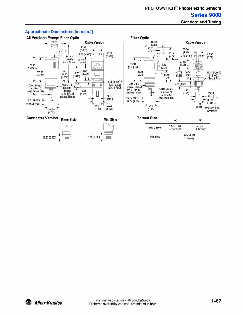
PHOTOSWITCHR Photoelectric Sensors
Series 9000Standard and Timing
1--67Visit our website: www.ab.com/catalogs.Preferred availability cat. nos. are printed in bold.
Approximate Dimensions [mm (in.)]
103.63(4.08)
Max. Travel
41.91(1.65)
Cable Length2 m (6.5 ft)6.47/6.22
(0.25/0.24) Dia.
40.0(1.57)
41.91(1.650)
5.46(0.215)
27.05(1.065)
40.00(1.575)
32.66 (1.286)
69.85(2.750)
74.93(2.950) Ref
55.62(2.190)
16.76 (0.660)
31.75(1.250)
M30 X 1.5ExternalThread
1/2 in. NPSMInternal Thread 24.69
(0.970)
30.35(1.195)
15.87(0.625)
47.75(1.880)
42.41(1.670)
20.96(0.825)
7.62 (0.300)
15.24(0.600)
5.21 (0.205) X8.13 (0.320)Slot, 2 PLCS
Cable Version
Cable Length2 m (6.5 ft )
6.5 (0.255/0.245)Dia.
31.75(1.25)
32.66 (1.28)
74.93(2.95) Ref
55.62(2.19)
16.76 (0.66)
M30 X 1.5External Thread1/2 in. NPSMInternal Thread 24.64
(0.97)30.35(1.19)
15.87 (0.62)
5.46(0.21)
42.42(1.67)
27.05(1.06)
20.96(0.82)7.62 (0.30)
15.24(0.60)
5.21 (0.20) X8.13 (0.32)Slot, 2 Plcs
13.33(0.52)
Mounting HoleCenterline
Cable Version
6.12(0.24)
Fiber OpticAll Versions Except Fiber Optic
103.63(4.080)
Max. Travel
69.85(2.75)
47.75(1.88)
13.97 (0.550) 17.78 (0.700)
Micro Style Mini StyleConnector Version Thread SizeAC DC
1/2--20 UNF2 Keyways
M12 x 11 Keyway
7/8--16 UN1 Keyway
Micro Style
Mini Style

PHOTOSWITCHR Photoelectric Sensors
Series 9000Standard and Timing
1--68 Visit our website: www.ab.com/catalogs.Preferred availability cat. nos. are printed in bold.
Typical Response Curve
12
4
810
20
40
80100
76 (3)Reflector
16 (0.625)Reflector
32 (1.25)Reflector
Large Aperture Fiber OpticTransmitted Beam
Large Aperture Fiber OpticRetroreflective
Large Aperture Fiber OpticStandard Diffuse
Visible Red Fiber OpticTransmitted Beam
OperatingMargin
OperatingMargin
Retroreflective Standard Diffuse
Distance [mm (in.)]
OperatingMargin
Distance [mm (in.)]
OperatingMargin
Distance [mm (in.)]
Transmitted Beamwith 61m (200ft) Light Source
OperatingMargin
Distance [m (ft)] Distance [mm (in.)] Distance [mm (in.)]
OperatingMargin
Distance [mm (in.)]
OperatingMargin
OperatingMargin
OperatingMargin
Distance [mm (in.)] Distance [mm (in.)] Distance [mm (in.)]
0.3m(1ft)
51(2)
15m(50ft)
1.5m(5ft)
0.6m(2ft)
3m(10ft)
51(2)
152(6)
1.5m(5ft)
0.3m(1ft)
6m(20ft)
3m(10ft)
15m(50ft)
Polarized Retroreflective
51(2)
1
2
4
810
20
40
80100
152(6)
1.5m(5ft)
0.6m(2ft)
3m(10ft)
6m(20ft)
0.3m(1ft)
White Paper,216 x 279.4(8.5 x 11)
Distance [mm (in.)]
Long Range Diffuse
1
1000
254(10)
2540(100)
25400(1000)
10
100
25.4(1)
9072
9040
Visible Red Fiber OpticStandard Diffuse
Small Aperture Fiber OpticRetroreflective
0.3(1)
104
1
10040
1000400
100004000
1.8(5)
3(10)
15(50)
30(100)
150(500)
900X
904X
OperatingMargin
OperatingMargin
25.4(1.0)
100004000
1000400
10040
104
10.6m(2ft)
2.54(0.1)
0.3m(12in.)
76.2(3.0)
White Paper216 X 279.4(8.5 x 11)2.3 (0.09) Glass Fiber
1.0 (0.04) Plastic Fiber
0.5 (0.02) Plastic Fiber
0.5 (0.02) Plastic Fiber Bundle
1.0 (0.04) Plastic Fiber-Coiled
0.3m(12in.)
25.4(1.0)
100004000
1000400
10040
104
10.6m(2ft)
2.54(0.1)
76.2(3.0)
1.5 (0.6) Glass Fiber
1.0 (0.04) Plastic Fiber
0.5 (0.02) Plastic Fiber
0.5 (0.06) PlasticFiber-Coiled
1.0 (0.04) PlasticFiber-Coiled
1.0 (0.04)Plastic Fiber
2.3 (0.09)Glass Fiber
With 76 (3)Reflector
0.5 (0.02)Plastic FiberCoiled
1.0 (0.04) PlasticFiber Coiled
0.5 (0.02)Plastic Fiber
100004000
1000400
10040
104
1
0.3m(12ft)
76.2(3.0)
0.6m(24ft)
2.54(0.1)
25.4(0.1)
1.5m(5ft)
0.61m(2ft)
152.4(6.0)
0.3m(12.0)
2.54(0.1)
25.4(1.0)
100004000
1000400
10040
10
41
White Paper216 x 279.4(8.5 x 11)
3.18 (0.125) Glass Fiber
1.52 (0.06) Glass Fiber
0.69 (0.027) Glass Fiber
0.69 (0.027) Glass Fiber
3.18 (1.25) Glass Fiber1.52 (0.060) Glass Fiber
100004000
1000400
10040
10
41
0.61m(2ft)
152.4(6.0)
0.3m(12.0)
2.54(0.1)
25.4(1.0)
1.52 (0.060)Glass Fiber
3.18 (0.125)Glass Fiber
0.69 (0.027)Glass Fiber
1.5m(5ft)
With 78 (3)Reflector
0.3m(12.0)
2.54(0.1)
25.4(1.0)
100004000
1000400
10040
10
41
12
4
810
20
40
80100
76 (3)Reflector
16 (0.625)Reflector
32 (1.25)Reflector
Product Selection for On/Off and Timing Sensors
Sensing ModeOperating VoltageSupply Current
SensingDistance
OutputEnergized
Output TypeCapacity
Response TimeConnection
Type Cat. No.
Retroreflective
Field of View: 1.5_Emitter LED: Visible red 660 nm
Objectto beSensed
10…30V DC30 mA
50.8 mm…9.14 m
(2 in…30 ft)with
76 mm (3 in.)Reflector
Light/DarkSelectable
NPN/PNP250 mA2 ms
2 m 300V cable 42G⊗U--9000
4-pin DC micro 42G⊗U--9000--QD
4-pin mini 42G⊗U--9000--QD1
70…264V AC/DC50/60 Hz15 mA
SPDT EM Relay2 A/132V AC1 A/264V AC1 A/150V DC
15 ms
2 m 300V cable 42G⊗U--9002
5-pin mini 42G⊗U--9002--QD
70…264V DC/40…264V AC50/6 0Hz15 mA
Solid State IsolatedN.O.300 mA2 ms
2 m 300V cable 42G⊗U--9003
2 m 600V cable 42G⊗U--9003H
4-pin mini 42G⊗U--9003--QD
4-pin AC micro 42G⊗U--9003--QD1
⊗ R for standard (i.e. 42GRU--9000); T for timing (i.e. 42GTU--9000)

PHOTOSWITCHR Photoelectric Sensors
Series 9000Standard and Timing
1--69Visit our website: www.ab.com/catalogs.Preferred availability cat. nos. are printed in bold.
Product Selection for On/Off and Timing Sensors
Sensing ModeOperating VoltageSupply Current
SensingDistance
OutputEnergized
Output TypeCapacity
Response TimeConnection
Type Cat. No.
Objectto beSensed
Polarized Retroreflective
Field of View: 1.5_Emitter LED: Visible red 660 nm
10…30V DC30 mA
50.8 mm…4.87 m(2 in…16 ft)
with 76 mm(3 in.) Reflector
Light/DarkSelectable
NPN/PNP250 mA2 ms
2 m 300V cable 42G⊗U--9200
4-pin DC micro 42G⊗U--9200--QD
4-pin mini 42G⊗U--9200--QD1
70…264V DC/60…264V AC50/60 Hz15 mA
SPDT EM Relay2 A/132V AC1 A/264V AC1 A/150V DC
15 ms
2 m 300V cable 42G⊗U--9202
5-pin mini 42G⊗U--9202--QD
70…264V DC/40…264V AC50/60 Hz15 mA
Solid State IsolatedN.O.300 mA2 ms
2 m 300V cable 42G⊗U--9203
2 m 600V cable 42G⊗U--9203H
4-pin mini 42G⊗U--9203--QD
4-pin AC micro 42G⊗U--9203--QD1
Objectto beSensed
Standard Diffuse
Field of View: 3.5_Emitter LED: Infrared 880 nm
10…30V DC30 mA
50.8 mm…1.52 m
(2 in…5 ft) toWhite Paper
Linear pot.Light/DarkSelectable NPN/PNP
100 mA2 ms
2 m 300V cable 42GLP--9000
4-pin DC micro 42GLP--9000--QD
TeachfunctionLight/DarkSelectable
2 m 300V cable 42GSP--9000
4-pin DC micro 42GSP--9000--QD
Light/DarkSelectable
NPN/PNP250 mA2 ms
2 m 300V cable 42G⊗P--9000
4-pin DC micro 42G⊗P--9000--QD
4-pin mini 42G⊗P--9000--QD1
70…264V DC/60…264V AC50/60 Hz15 mA
SPDT EM Relay2 A/132V AC1 A/264V AC1 A/150V DC
15 ms
2 m 300V cable 42G⊗P--9002
5-pin mini 42G⊗P--9002--QD
70…264V DC/40…264V AC50/60 Hz15 mA
Solid State IsolatedN.O.300 mA2 ms
2 m 300V cable 42G⊗P--9003
2 m 600V cable 42G⊗P--9003H
4-pin mini 42G⊗P--9003--QD
4-pin AC micro 42G⊗P--9003--QD1
Objectto beSensed
Long Range Diffuse
Field of View: 6.5_Emitter LED: Infrared 880 nm
10…30V DC30 mA
50.8 mm…3.04 m
(2 in…10 ft)
Light/DarkSelectable
NPN/PNP250 mA2 ms
2 m 300V cable 42GRP--9040
4-pin DC micro 42GRP--9040--QD
4-pin mini 42GRP--9040--QD1
70…264V AC/DC50/60 Hz15 mA
SPDTEM Relay2 A/132V AC1 A/264V AC1 A/150V DC
15 ms
2 m 300V cable 42GRP--9042
5-pin mini 42GRP--9042--QD
70…264V DC/40…264V AC50/60 Hz15 mA
Solid State IsolatedN.O.300 mA2 ms
2 m 300V cable 42GRP--9043
2 m 600V cable 42GRP--9043H
4-pin mini 42GRP--9043--QD
4-pin AC micro 42GRP--9043--QD1
10…40V DC30 mA
50.8 mm…4.2 m(2 in…14ft)
Light/DarkSelectable
NPN/PNP250 mA2 ms
2 m 300V cable 42GRP--9070
4-pin DC micro 42GRP--9070--QD
70…264V AC/DC50/60 Hz15 mA
SPDTEM Relay2 A/132V AC1 A/264V AC1 A/150V DC
15 ms
2 m 300V cable 42GRP--9072
3 m 300V cable 42GRP--9072--3
5-pin mini 42GRP--9072--QD
⊗ R for standard (i.e. 42GRU--9000); T for timing (i.e. 42GTU--9000)
Refer to page 1--71 for cordsets and accessories.

PHOTOSWITCHR Photoelectric Sensors
Series 9000Standard and Timing
1--70 Visit our website: www.ab.com/catalogs.Preferred availability cat. nos. are printed in bold.
Product Selection (continued)
Sensing ModeOperating VoltageSupply Current
SensingDistance
OutputEnergized
Output TypeCapacity
Response TimeConnection
Type Cat. No.
Transmitted Beam
Field of View: 1.5_Emitter LED: Infrared 880 nm
Objectto beSensed
10…264V AC/DC50/60 Hz15 mA
25.4 mm…61 m(1 in…200 ft)
NALight Source
2 m 300V cable 42GRL--9000
2 m 600V cable 42GRL--9000H
4-pin DC micro 42GRL--9000--QD
4-pin mini 42GRL--9002--QD
25.4 mm…152 m
(1 in…500 ft)
2 m 300V cable 42GRL--9040
4-pin DC micro 42GRL--9040--QD
4-pin mini 42GRL--9042--QD
4-pin AC micro 42GRL--9043--QD1
10…30V DC25 mA
Depends onLight Source
Receiver
Light or DarkOutput
Selectable
NPN and PNP250 mA5 ms
2 m -300Vcable 42G R--9000
4-pin DC micro 42G R--9000--QD
4-pin mini 42G R--9000--QD1
70…264V AC/DC,50/60 Hz10 mA
SPDT EM Relay2 A/132V AC,1 A/264V AC1 A/150V DC
23 ms
2 m 300V cable 42G R--9002
5-pin mini 42G R--9002--QD
70…264V DC,40…264V AC50/60 Hz10 mA
Solid State IsolatedN.O.300 mA15 ms
2 m 300V cable 42GRR--9003
2 m 600V cable 42GRR--9003H
4-pin mini 42GRR--9003--QD
4-pin AC micro 42GRR--9003--QD1
Objectto beSensed
Small Aperture Red Fiber Optic
Emitter LED: Visible red 660 nm
10…30V DC30 mA
Depends onFiber Opticcable
Light/DarkSelectable
NPN/PNP250 mA2 ms
2 m 300V cable 42G F--9100
4-pin DC micro 42G F--9100--QD
70…264V AC/DC50/60 Hz15 mA
SPDT EM Relay2 A/132V AC,1 A/264V AC1 A/150V DC
15 ms
2 m 300V cable 42G F--9102
5-pin mini 42G F--9102--QD
70…264V DC/40…264V AC50/60 Hz15 mA
Solid State IsolatedN.O.300 mA2 ms
2 m 300V cable 42G F--9103
4-pin mini 42G F--9103--QD
4-pin AC micro 42G F--9103--QD1
Objectto beSensed
Large Aperture Fiber Optic
Emitter LED: Infrared 880 nm
10…30V DC30 mA
Depends onFiber Opticcable
Light/DarkSelectable
NPN/PNP250 mA2 ms
2 m 300V cable 42G F--9000
4-pin DC micro 42G F--9000--QD
70…264V AC/DC,50/60 Hz15 mA
SPDT EM Relay2 A/132V AC,1 A/264V AC1 A/150V DC
15 ms
2 m 300V cable 42G F--9002
5-pin mini 42G F--9002--QD
70…264V DC/40…264V AC50/60 Hz15 mA
Solid State IsolatedN.O.300 mA2 ms
2 m 300V cable 42G F--9003
2 m 600V cable 42G F--9003H
4-pin mini 42G F--9003--QD
4-pin AC micro 42G F--9003--QD1
⊗ R for standard (i.e. 42GRU--9000); T for timing (i.e. 42GTU--9000)

PHOTOSWITCHR Photoelectric Sensors
Series 9000Standard and Timing
1--71Visit our website: www.ab.com/catalogs.Preferred availability cat. nos. are printed in bold.
Product Selection (continued)
Sensing ModeOperating VoltageSupply Current
SensingDistance
OutputEnergized
Output TypeCapacity
Response TimeConnection
Type Cat. No.
Extended Range Large Aperture Fiber Optic
Emitter LED: Infrared 880 nm
Objectto beSensed
10…264V AC/DC,56/60 Hz15 mA
See table below. NALight Source
2 m 300V cable 42GRLF--9040
4-pin DC micro 42GRLF--9040--QD
10…40V DC30 mA
See table below. Light/DarkSelectable
NPN/PNP250 mA2 ms
2 m 300V cable 42GRRF--9000
4-pin DC micro 42GRRF--9000--QD
70…264V AC/DC,50/60 Hz15 mA
SPDT EM Relay2 A/132V AC,1 A/264V AC1 A/150V DC
15 ms
2 m 300V cable 42GRRF--9002
5-pin mini 42GRRF--9002--QD
Typical Sensing Distance—Extended Range Infrared Fiber Optic
Sensing Mode Sensor Fiber Optic CableRangeExtender
SensingDistance
(1X margin.)
Transmitted Beam
42GRLF--9040 with individualfiber optic cable
43GT--FAS25SL Individual Fiber Optic Cable,smooth tip
none 914 mm (36 in.)43GT--TBB25SL Individual Fiber Optic Cable, with
5/16 inch threaded tip
43GT--FAS25SL Individual Fiber Optic Cable,smooth tip
60--1844 6 m (20 ft)
60--2559 12 m (40 ft)
43GT--TBB25SL Individual Fiber Optic Cable, with5/16 inch threaded tip
60--2323 6 m (20 ft)
60--2738 12 m (40 ft)
42GRLF--9040 with bifurcatedfiber optic cable
43GR--FAS25SL Bifurcated Fiber Optic Cable,smooth tip
none 1.2 m (48 in.)43GR--TBB25SL Bifurcated Fiber Optic Cable, with
5/16 inch threaded tip
43GR--FAS25SL Bifurcated Fiber Optic Cable, withsmooth tip
60--1844 7.6 m (25 ft)
60--2559 15.2 m (50 ft)
43GR--TBB25SL Bifurcated Fiber Optic Cable, with5/16 inch threaded tip
60--2323 7.6 m (25 ft)
60--2738 15.2 m (50 ft)
1. Sensing ranges are for fiber optic cables shown. Range will vary with other fiber optic cable types.2. When using individual fiber optic cable, second port must be blocked with the provided plug (60--2744).3. Receiver Sensor (42GRRF) requires only individual fiber optic cable.
Cordsets and Accessories
Description Cat. No. Description Cat. No.
1.8 m (6 ft) 4-pin, Mini QD Cordset 889N--F4AF--6F 32 mm (1.25 in.) Diameter Reflector 92--47
1.8 m (6 ft) 5-pin, Mini QD Cordset 889N--F5AF--6F Range Extender 60--1844
2 m (6.5 ft) 4-pin, DC Micro QD Cordset 889D--F4AC--2 Range Extender 60--2559
2 m (6.5 ft) 4-pin, AC Micro QD Cordset 889R--F4AEA--2 Range Extender 60--2738
76 mm (3 in.) Diameter Reflector 92--39 Replacement Plug 60--2744

PHOTOSWITCHR Photoelectric Sensors
44B Adjustable Background and Foreground Suppression50 mm Rectangular
1--72 Visit our website: www.ab.com/catalogs.Preferred availability cat. nos. are printed in bold.
Features
S Adjustable background andforeground suppression models
S Power, output, and stability statusindicators
S Micro QD connection with 90_swivel
S Low voltage 24V DC operation
S Protected from miswiring
S Dual NPN and PNP outputs
S Fast 1 ms response time
SpecificationsEnvironmentalCertifications cULus and CE Marked for all applicable directives
Operating Environment NEMA 3, 4X, 6P, 12, 13, IP67
Operating Temperature [C (F)] 0…+70° (32…+158°)
Vibration 10…55 Hz, 1 mm amplitude, meets or exceeds IEC 947--5--2
Shock 30 g with 1 ms pulse duration, meets or exceeds IEC 947--5--2
Relative Humidity 5…95%
OpticalSensing modes Background suppresion or foreground suppression
Sensing Range 20…300 mm (0.78…11.8 in.) adjustable for background suppression20…200 mm (0.78…7.8 in.) adjustable for foreground suppression
Spot Size See Product Selection table on page 1--74
Light Source Infrared LED (880 nm)
LED Indicators See User Interface Panel below
Adjustments 6-turn adjustment knob
ElectricalVoltage 20…30V DC
Current Consumption 22 mA max
Sensor Protection False pulse, reverse polarity, overload, output short circuit
OutputsResponse Time 1 ms max
Output Type PNP and NPN
Output Mode Light or dark operate by cat. no.
Output Current 100 mA
Output Leakage Current 10 μA max
MechanicalHousing Material Acrylic
Lens Material Acrylic
Connection Types 4-pin DC micro (M12) QD
Supplied Accessories None
Optional Accessories See mounting brackets and cordsets on page 1--73
User Interface Panel
Color State Status AdjustableKnob
Micro QDSwivel
LED StatusIndicators
Green
OFF Sensor not powered, SCP active
ON Sensor powered
Flashing Unstable margin
OrangeOFF Output not activated
ON Output activated

PHOTOSWITCHR Photoelectric Sensors
44B Adjustable Background and Foreground Suppression50 mm Rectangular
1--73Visit our website: www.ab.com/catalogs.Preferred availability cat. nos. are printed in bold.
Approximate Dimensions [mm (in.)]
42.55 (1.67)
51.18(2.01)
63.50(2.50)
13.97(0.55)
67.38(2.65)
Optional DovetailBracket 44B--BKT
13.98(0.55)
7.11(0.28)
10(0.39)
30.7 (1.21)
14.99(0.59)
Optional DovetailBracket 44B--BKT
Wiring DiagramDovetail Bracket(Optional)44B-BKT
Cordsets & Accessories
Description Cat. No.
2 m (6.5 ft) 4-pin, DC Micro QD Cordset 889D--F4AC--2
Dovetail Bracket 44B--BKT
Mounting Bracket 60--BKTL--SS
NPN/PNP
Black
+
--
1
2
4
3
Quick-Disconnect
BrownWhite
Blue
Micro
34
2
1

PHOTOSWITCHR Photoelectric Sensors
44B Adjustable Background and Foreground Suppression50 mm Rectangular
1--74 Visit our website: www.ab.com/catalogs.Preferred availability cat. nos. are printed in bold.
Typical Response Curve Typical Response CurveSensing Distance
SuppressionDistance
Background
Suppression Point
SensingDistance
BackgroundSuppression Point
Background Suppression Foreground Suppression
0 100 200 300
0
50
100
150
200
250
300
Suppression Distance [mm (in.)]
SensingDistance[mm(in.)]
0 100 20050
0
50
100
150
200
250
300
Suppression Distance [mm (in.)]
SensingDistance[mm(in.)]
150
90%White
3%Black
90%White
3%Black
Example: With a suppression point set at 200 mm, thesensing distance will be between the sensor face and justunder 200 mm for 90% white reflective targets andbetween 12 mm and 185mm for 3% black reflectivetargets.
Example: With a suppression point set at 50 mm, thesensing distance will be between just over 50 mm and 150mm for 90% white reflective targets and between just over50 mm and 100 mm for 3% black reflective targets.
Product Selection
Sensing ModeOperating VoltageSupply Current
SensingDistance
(Adjustable)LEDSource
OutputEnergized
Output Type/Capacity
Response TimeConnection
Type Cat. No.
Background Suppression20 mm spot size @ 300 mm
Objectto beSensed
Back-ground
20…30V DC22 mA
20…300 mm(0.78…11.8 in)
Infrared880 nm
LightOperate
PNP and NPN100 mA1 ms
4-pin DC micro
44BSB--1JBA1--D4
DarkOperate 44BSB--1KBA1--D4
Foreground Suppression15 mm spot size @ 200 mm
Objectto beSensed
Back-ground
20…200 mm(0.78…7.9 in)
DarkOperate 44BSN--1KBA1--D4
LightOperate 44BSN--1JBA1--D4
Detection by presence of reflected light from the target.Detection by absence of reflected light from the background.
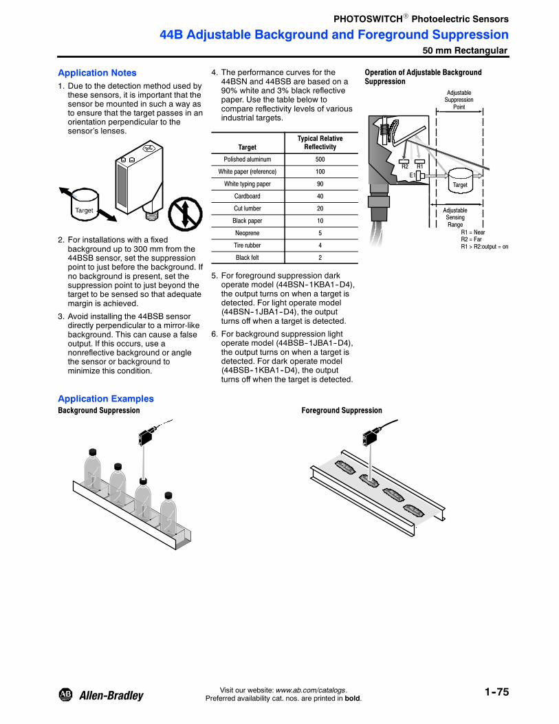
PHOTOSWITCHR Photoelectric Sensors
44B Adjustable Background and Foreground Suppression50 mm Rectangular
1--75Visit our website: www.ab.com/catalogs.Preferred availability cat. nos. are printed in bold.
Application Notes1. Due to the detection method used by
these sensors, it is important that thesensor be mounted in such a way asto ensure that the target passes in anorientation perpendicular to thesensor’s lenses.
2. For installations with a fixedbackground up to 300 mm from the44BSB sensor, set the suppressionpoint to just before the background. Ifno background is present, set thesuppression point to just beyond thetarget to be sensed so that adequatemargin is achieved.
3. Avoid installing the 44BSB sensordirectly perpendicular to a mirror-likebackground. This can cause a falseoutput. If this occurs, use anonreflective background or anglethe sensor or background tominimize this condition.
4. The performance curves for the44BSN and 44BSB are based on a90% white and 3% black reflectivepaper. Use the table below tocompare reflectivity levels of variousindustrial targets.
TargetTypical RelativeReflectivity
Polished aluminum 500
White paper (reference) 100
White typing paper 90
Cardboard 40
Cut lumber 20
Black paper 10
Neoprene 5
Tire rubber 4
Black felt 2
5. For foreground suppression darkoperate model (44BSN--1KBA1--D4),the output turns on when a target isdetected. For light operate model(44BSN--1JBA1--D4), the outputturns off when a target is detected.
6. For background suppression lightoperate model (44BSB--1JBA1--D4),the output turns on when a target isdetected. For dark operate model(44BSB--1KBA1--D4), the outputturns off when the target is detected.
Operation of Adjustable BackgroundSuppression
AdjustableSuppression
Point
AdjustableSensingRange
Target
R1R2E1
R1 = NearR2 = FarR1 > R2:output = on
Application ExamplesBackground Suppression Foreground Suppression

PHOTOSWITCHR Photoelectric Sensors
42BT Long Range Background SuppressionSlim Flatpack
1--76 Visit our website: www.ab.com/catalogs.Preferred availability cat. nos. are printed in bold.
Features
S Long range backgroundsuppression diffuse sensing mode
S Adjustable range settings
S Slim flatpack housing design
S Highly visible LED Indicators
S Pico QD and 2 m cable versions
S Both NPN and PNP outputs
S Short-circuit protected outputs
S Fast 2 ms response time
SpecificationsEnvironmentalCertifications cULus Listed and CE Marked for all applicable directives
Operating Environment IP65
Operating Temperature [C (F)] --5…+55° (+23…+131°)
Vibration 10…55 Hz, 1 mm amplitude, meets or exceeds IEC 60947--5--2
Shock 30 g with 1 ms pulse duration, meets or exceeds IEC 60947--5--2
Relative Humidity 35…85%
Ambient Light Immunity Incandescent light: 3000 lux, sunlight immunity: 10000 lux
OpticalSensing Modes Background suppression
Sensing Range 1 m or 2 m by cat. no.
Field of View See Product Selection table on page 1--77
Light Source Visible red LED (650 nm), infrared LED (880 nm)
LED Indicators See User Interface Panel below
Adjustments 5-turn sensitivity potentiometer
ElectricalVoltage 12…24V DC
Current Consumption 30 mA
Sensor Protection Short circuit
OutputsResponse Time 2 ms max
Output Type PNP and NPN
Output Mode Light operate or dark operate selectable
Output Current 100 mA @ 24V DC
Output Leakage Current 0.1 mA max
MechanicalHousing Material Polyarilate
Lens Material Polyarilate
Connection Types 2 m cable, 4-pin pico (M8) QD on 6-inch pigtail
Supplied Accessories Screwdriver
Optional Accessories See mounting brackets and cordsets on page 1--77
User Interface Panel
Label Color State Status
OutputIndicator
MarginIndicator
Range AdjustmentSelector
Light/DarkOperate Switch
Range AdjustmentDisplay
Margin GreenOFF Margin < 2.5
ON Margin > 2.5
Status RedOFF Output not activated
ON Output activated

PHOTOSWITCHR Photoelectric Sensors
42BT Long Range Background SuppressionSlim Flatpack
1--77Visit our website: www.ab.com/catalogs.Preferred availability cat. nos. are printed in bold.
Wiring Diagrams Approximate Dimensions [mm (in.)]
Black
NPN/PNPBrown
Blue
White
Black +
--
+
--
1
2
4
3
Cable Quick-Disconnect
Brown
White
Blue
Pico 20(0.78)
70(2.75)
2--4.2 (0.17)Dia.
57.5(2.26)
40(1.57)
15 (0.59)Axis
5.5 (0.21)20.5 (0.80)
2 m cable4.2 (0.17) Dia.
Black +
--
1
2
4
3
Quick-Disconnect
Brown
White
Blue
Micro
3
2
1
4
43
1
2
Typical Response Curve Beam Pattern42BT--B1LBSN 42BT--B2LBSL
Typical Response Curve Beam Pattern
0 0.4(1.3)
0.8(2.6)
1.2(3.9)
1.6(5.2)
2.0(6.5)
1
101
201
301
401
501
601
701
Distance [m (ft)]
OperatingMargin
0
10
20
Beam
Diameter—mm
--10
--20
0 360(14.1)
720(28.3)
1080(42.5)
1440(56.7)
Distance [mm (in.)]
2040(80.3)
1800(70.9)
Distance [m (ft)]
1
51
101
151
201
OperatingMargin
0 0.4(1.3)
0.8(2.6)
1.2(3.9)
1.6(5.2)
2.0(6.5)
0
10
20
Beam
Diameter—mm
--10
--20
0 200(7.87)
400(15.7)
600(23.6)
800(31.5)
Distance [mm (in.)]
1200(47.2)
1000(39.4)
Product Selection
Sensing ModeOperating VoltageSupply Current
SensingDistance
LEDSource
OutputEnergized
Output Type/Capacity
Response TimeConnection
Type Cat. No.
Background Suppression
Field of View: 1.7_ 12…24V DC10%30 mA
0.2…1 m(0.66…3.3 ft)
Visible Red650 nm
L.O./D.O.selectable
PNP and NPN2 ms (max)
2 m 300V cable 42BT--B2LBSL--A2
4-pin DC micro 42BT--B2LBSL--F4
4-pin DC pico 42BT--B2LBSL--Y4
Background Suppression
Field of View: 2.8_
0.2…2 m(0.66…6.4 ft)
Infrared880 nm
2 m 300V cable 42BT--B1LBSN--A2
4-pin DC micro 42BT--B1LBSN--F4
4-pin DC pico 42BT--B1LBSN--Y4
Cordsets and AccessoriesDescription Cat. No. Description Cat. No.
2 m (6.5 ft) 4-pin, DC Micro QD Cordset 889D--F4AC--2 Vertical Mounting Bracket 61--6738
2 m (6.5 ft) 4-pin, Pico QD Cordset 889P--F4AB--2 Horizontal Mounting Bracket 61--6739

PHOTOSWITCHR Photoelectric Sensors
42BC Long Range Background SuppressionSlim Housing
1--78 Visit our website: www.ab.com/catalogs.Preferred availability cat. nos. are printed in bold.
Features
S Long range backgroundsuppression diffuse sensing mode
S Adjustable range settings
S Slim housing style
S Highly visible LED Indicators
S Screw terminal connections
S Both NPN and PNP outputs (DC)
S SPST relay output (AC)
S Short-circuit protected outputs
SpecificationsEnvironmental
Certifications UL Listed, CSA Certified and CE Marked for all applicable directives
Operating Environment NEMA 1, 12, 13, IP65
Operating Temperature [C (F)] --25…+55° (--13…+131°)
Vibration 10…55 Hz, 1 mm amplitude, meets or exceeds IEC 60947--5--2
Shock 30 g with 1 ms pulse duration, meets or exceeds IEC 60947--5--2
Relative Humidity 5…85%
Ambient Light Immunity Incandescent light: 3000 lux, sunlight immunity: 10000 lux
Optical
Sensing Modes Background suppression
Sensing Range 1 m or 2 m by cat. no.
Field of View See Product Selection table on page 1--80
Light Source Infrared LED (880 nm)
LED Indicators See User Interface Panel below
Adjustments Sensitivity potentiometer
Electrical
Voltage 12…24V DC, 24…240V DC
Current Consumption 30 mA
Sensor Protection Short circuit for DC models, reverse polarity, false pulse, transient
Outputs
Response Time 20 ms max (DC models), 30 ms max (AC models)
Output Type PNP and NPN, SPDT N.O. relay (AC models)
Output Mode Light operate or dark operate selectable
Output Current 100 mA @ 24V DC, 3 A @ 240V AC
Output Leakage Current 0.5 mA max
Mechanical
Housing Material Polycarbonate
Lens Material Polycarbonate
Cover Material Acrylic
Connection Types Screw terminal, 16 AWG (1.3 mm2 )
Supplied Accessories Right angle mounting bracket
Optional Accessories See mounting brackets and cordsets on page 1--80
User Interface Panel
Label Color State Status
Stability IndicatorRange Adjustment
Output IndicatorLight Operate/DarkOperate Switch
Far
Near
Margin GreenOFF 0.8>margin<1.2
ON 0.8<margin>1.2
Output RedOFF Output not activated
ON Output activated

PHOTOSWITCHR Photoelectric Sensors
42BC Long Range Background SuppressionSlim Housing
1--79Visit our website: www.ab.com/catalogs.Preferred availability cat. nos. are printed in bold.
Wiring Diagrams
Relay Output Type Solid-State Output Type
Terminal Version
2
1
4
3
24…240V AC/DC
Output 24…250VAC/DC 3 A Max
Terminal No.
2
1
4
3
+12…24V DC
PNP Output
Terminal No.
--DC
NPN Output
Approximate Dimensions [mm (in.)]
69(2.71)
68(2.67)
35(1.37)
2--Dia. 5.2(0.20)2 Places
26(1.02)
50 (1.96)12
(0.47) 68 (2.67)
23.5 (0.92)
5.5 (0.21)
17(0.669)
Removable, see-throughsnap on wiring Cover
Lens
11.5 (0.45)
OpticalAxis
Detection DirectionDue to the detection method, the sensor must be positioned such that the target passes in the direction illustrated.
Motion in up/down direction cannot be detected.
Target
Minimum Sensing Distances
Near Setting
2.5% black 8 cm (3.15 in.) at 2X margin100% white 3 cm (1.18 in.) at 2X margin
Far Setting
2.5% black 20 cm (7.9 in.) at 2X margin100% white 4 cm (1.57 in.) at 2X margin
Typical Response Curve Beam Pattern1 m Background Suppression
Distance [m (ft)]
OperatingMargin
Distance [m (ft)]
Beam
Diameter—cm
Typical Response Curve Beam Pattern
OperatingMargin
Distance [m (ft)]
Beam
Diameter—cm
Distance [m (ft)]
1
10
100
0 0.1(0.3)
1(3.2)
--3
--2
--1
0
1
2
3
0 0.2(0.67)
0.4(1.31)
0.6(1.97)
0.8(2.63)
1(3.28)
2 m Background Suppression
1
10
100
0.1(0.3)
1(3.2)
10(32.8)
--8--6
--4
--2
0
2
4
6
8
0 0.4(1.31)
0.8(2.63)
1.2(3.94)
1.6(5.25)
2(6.56)

PHOTOSWITCHR Photoelectric Sensors
42BC Long Range Background SuppressionSlim Housing
1--80 Visit our website: www.ab.com/catalogs.Preferred availability cat. nos. are printed in bold.
Product Selection
Sensing ModeOperating VoltageSupply Current
SensingDistance
OutputEnergized
Output TypeCapacity
Response TimeConnection
Type Cat. No.
Objectto beSensed
Background
Background Suppression
Field of View: 3.5_Minimum Sensing Distance: 30 mm (1.2 in.)Emitter LED: Infrared 880 nm
12…24V DC ±10%30 mA
1 m (3.3 ft)
Light/DarkSelectable
NPN/PNP100 mA20 ms Screw
terminalsaccepts up to(2) 16 AWG(1.3 mm sq.)conductors
42BC--B1LBAL--T4
2 m (6.6 ft) 42BC--B1LBAN--T4
24…240V AC/DC±10%
30 mA (DC)15 mA (AC)
1 m (3.3 ft) S.P.S.T. N.O. Relay3 A (250V AC,750V AC)
3 A (30V DC, 90 W)30 ms
42BC--B1CRAL--T4
2 m (6.6 ft) 42BC--B1CRAN--T4
Cordsets and Accessories
Description Cat. No.
DC Micro QD Cordset, Straight, 4-pin, 2 m 889D--F4AC--2
Receptacle, 4-pin DC Micro QD 888D--M4AC1--0M3
Mounting Bracket 60--2637
Replacement Cover 60--2669
Receptacle, 4-pin Mini QD 60--2668

PHOTOSWITCHR Photoelectric Sensors
42BA Short Range Background SuppressionCompact Housing
1--81Visit our website: www.ab.com/catalogs.Preferred availability cat. nos. are printed in bold.
Features
S Short-range backgroundsuppression diffuse sensing mode
S Adjustable range settings
S Compact housing style
S Highly visible LED indicators
S NPN or PNP output models
S Diagnostic output
S Short-circuit protected outputs
S 2 m cable connection
SpecificationsEnvironmentalCertifications UL Listed, CSA Certified, and CE Marked for all applicable directives
Operating Environment NEMA 1, 4, 6P, 12, 13, IP67 (IEC 529)
Operating Temperature [C (F)] --25…+55° (--13…+131°)
Vibration 10…55 Hz, 1 mm amplitude, meets or exceeds IEC 60947--5--2
Shock 30 g with 1 ms pulse duration, meets or exceeds IEC 60947--5--2
Relative Humidity 5…85%
OpticalSensing Mode Background suppression
Sensing Range See Product Selection table on page 1--83
Field of View See Product Selection table on page 1--83
Light Source Visible red LED (700 nm), infrared LED (880 nm)
LED Indicators See User Interface Panel below
Adjustments Sensitivity potentiometer
ElectricalVoltage 10…30V DC
Current Consumption 33 mA max
Sensor Protection Short circuit, reverse polarity, false pulse, transient noise
OutputsResponse Time 350 μs
Output Type PNP or NPN by cat. no.
Output Mode Light operate or dark operate selectable
Output Current 100 mA max @ 24V DC
Output Leakage Current 1 μA max
MechanicalHousing Material Polyarylate (30 mm and 50 mm models)
ABS resin (100 mm and 200 mm models)
Lens Material Polyarylate (30 mm and 50 mm models)
Polysulfone (100 mm and 200 mm models)
Connection Types 2 m cable
Supplied Accessories 60--2636 mounting bracket
User Interface PanelLabel Color State Status Sensitivity
PotentiometerStabilityIndicator
OutputIndicator
SensitivityPotentiometer
Light Operate/DarkOperate Switch
StabilityIndicatorOutputIndicator
STB GreenOFF 0.8>margin<1.2ON 0.8<margin>1.2
OUT RedOFF Output not activatedON Output activated
Wiring DiagramsNPN Output PNP Output
Black: Output
Brown: +12V…24V DC
Cable
Blue: --DC
Orange: Stability Output
Load
Black: Output
Brown: +12V…24V DC
Cable
Blue: --DC
Load
Load
Note: Details regarding connection of Rockwell Automation 42BA photoelectric sensors to Rockwell Automation Programmable Controllerscan be found in “PHOTOSWITCHR Photoelectric Sensors and Programmable Controller Interface Manual” onwww.ab.com/Literature.

PHOTOSWITCHR Photoelectric Sensors
42BA Short Range Background SuppressionCompact Housing
1--82 Visit our website: www.ab.com/catalogs.Preferred availability cat. nos. are printed in bold.
Approximate Dimensions [mm (in.)]
3(0.12)
8(0.31)
25 (0.98)
35(1.38)29
(1.14)
8(0.31)
2(0.08)
2--Dia. 3.1 (0.122)2 Places
100 mm and 200 mm Sensing Distance Versions
Lens
15 (0.59)
3(0.12)
25.4(1.0)
3.2(0.13)
19(0.75)
2--Dia. 3.1(0.12)2 Places
1(0.04)
2(0.08)
16.4(0.65)
LightOperate/DarkOperateSwitch
L.O.
D.O.
30 mm and 50 mm Sensing Distance Versions
Lens12.7(0.5)
17.5(0.69)
Stainless Steel Mounting Bracket—60--2636
Stainless steel mounting bracket and hardware supplied with all 42BA sensors.
15.0 (0.59)11.5(0.59)
11(0.4)
15 (0.59)
Dia. 3.5(0.2)
7.8(0.30)
8.0(0.31)
14.0(0.55)
R 2 (0.1) 2 PlR 0.5 (0.01) 2 Pl
3.5(0.14)
6.0(0.23)
43.5(1.7)
39.5(1.5)
21.0 (0.8)
Dia. 3.2 (1.2)2 Places
25(0.9)
R5 2 Places
3.2(0.1)
16° 16°
30 (1.2)
Bottom View Side View
Note: Replacement mounting assemblies and reflectors available on page 1--293.
15.0 (0.59)
Typical Response Curve Beam Pattern30 mm 50 mm
Distance [mm (in.)]
OperatingMargin
Distance [mm (in.)]
Beam
Diameter—mm
Typical Response Curve Beam Pattern
OperatingMargin
Beam
Diameter—mm
100 mm 200 mm
OperatingMargin
Beam
Diameter—mm
OperatingMargin
Beam
Diameter—mm
1
10
100
1(0.03)
10(0.39)
100(3.93)
--2
--1
0
1
2
0 10(0.39)
20(0.78)
30(1.18)
1
10
100
0.1(0.003)
1(0.03)
10(0.39)
100(3.93)
--3
--1
0
1
3
0 10(0.39)
50(1.96)
30(1.18)
Distance [mm (in.)] Distance [mm (in.)]
1
10
100
1(0.03)
10(0.39)
100(3.93i)
0 20(0.78)
60(2.36)
100(3.93)
--5
--3
--10
2
5
1
10
100
1(0.03)
10(0.39)
100(3.93)
1000(39.3)
0 40(1.57)
120(4.72)
200(7.87)
80(3.15)
--5
--3
--1
0
2
5
1
3
4
--2
--4
160(6.29)
Distance [mm (in.)] Distance [mm (in.)] Distance [mm (in.)] Distance [mm (in.)]

PHOTOSWITCHR Photoelectric Sensors
42BA Short Range Background SuppressionCompact Housing
1--83Visit our website: www.ab.com/catalogs.Preferred availability cat. nos. are printed in bold.
Product Selection
Sensing ModeOperating VoltageSupply Current
SensingDistance[mm (in.)]
FieldofView
OutputEnergized
LEDSource
Output TypeCapacity
Response TimeConnection
Type Cat. No.
Objectto beSensed
12…24V DC ±10%27 mA
10…30(0.39…1.2)
9_
Light/DarkSelectable
Visible red700 nm
NPNOutput: 100 mA,Stability: 50 mA
350 μs
2 m 500Vcable
42BA--S2LNAA--A2
12…24V DC ±10%30 mA
PNPOutput: 100 mA,
350 μs42BA--S2LPAA--A2
12…24V DC ±10%27 mA
10…50(0.39…2.0)
NPNOutput: 100 mA,Stability: 50 mA
350 μs
42BA--S2LNAC--A2
12…24V DC ±10%30 mA
PNPOutput: 100 mA,
350 μs42BA--S2LPAC--A2
10…100(0.39…3.9)
NPNOutput: 100 mAStability: 50 mA
350 μs
42BA--S2LNAE--A2
12…24V DC ±10%33 mA
PNPOutput: 100 mA
350 μs42BA--S2LPAE--A2
12…24V DC ±10%30 mA
10…200(0.39…7.9) 5_ Infrared
880 nm
NPNOutput: 100 mAStability: 50 mA
350 μs
42BA--S1LNAG--A2
12…24V DC ±10%33 mA
PNPOutput: 100 mA
350 μs42BA--S1LPAG--A2
Operating Distance with White Paper
Min Sensitivity [mm (in.)] Max Sensitivity [mm (in.)] Cat. No.
12…25(0.47…0.98)
2…30(0.078…1.18)
42BA--S2LNAA--A242BA--S2LPAA--A2
9.5…39(0.37…1.54)
2.7…50(0.106…1.97)
42BA--S2LNAC--A242BA--S2LPAC--A2
17…75(0.67…2.95)
6…100(0.24…3.94)
42BA--S2LNAE--A242BA--S2LPAE--A2
25…160(0.98…6.29)
1…200(0.039…7.87)
42BA--S1LNAG--A242BA--S1LPAG--A2
Detection Direction
Due to the detection method, the sensor must be positioned such that the target passes in the horizontal direction illustrated.
Target
Motion in the vertical direction cannot be reliably detected.

PHOTOSWITCHR Photoelectric Sensors
42KAUltra-Miniature Flat Pack
1--88 Visit our website: www.ab.com/catalogs.Preferred availability cat. nos. are printed in bold.
Features
S Subminiature package style
S Three sensing modes
S Models with and without sensitivityadjustment
S Highly visible LED Indicators
S NPN or PNP output models
S 2 m cable connection
SpecificationsEnvironmentalCertifications UL Listed, CSA Approved, and CE Marked for all applicable directives
Operating Environment NEMA 1, IP40
Operating Temperature [C(F)] --25…+55° (--13…+131°)
Vibration 10…55 Hz, 1 mm amplitude, meets or exceeds IEC 60068--2--6
Shock 30 g with 1 ms pulse duration, meets or exceeds IEC 60068--2--27
Relative Humidity 5…85%
OpticalSensing Modes Diffuse, sharp cutoff, transmitted beam
Sensing Range See Product Selection table on page 1--91
Field of View See Product Selection table on page 1--91
Light Source Visible red LED (660 nm)
LED Indicators See User Interface below
Adjustments See Product Selection table on page 1--91
ElectricalVoltage 12…24V DC
Current Consumption 30 mA max
Sensor Protection Reverse polarity for standard diffuse without adjustment, transientnoise
Outputs
Response Time 500 μS
Output Type PNP or NPN by cat. no.
Output Mode See Product Selection table on page 1--91
Output Current 80 mA @ 24V DC
Output Leakage Current 0.5 mA max
Mechanical
Housing Material Polyester
Lens Material Polycarbonate
Connection Types 2 m cable
User Interface Panel Wiring DiagramsLabel Color State Status NPN Output PNP Output
STB Green
OFF 0.8<margin<1.2
Black: Output
Blue: --DC
Brown: 24V DC (Transmitted Beam)12…24V DC (All Other Models)
Cable
LoadBlack: Output
Blue: --DC
Brown: 24V DC (Transmitted Beam)12…24V DC (All Other Models)
Load
Cable
ON 0.8>margin>1.2
OUT Red
OFF Output not activated
ON Output activated
Note: Details regarding connection of Rockwell Automation Bulletin 42KA photoelectric sensors to Rockwell Automation Programmable Controllerscan be found in publication 42-2.0.

PHOTOSWITCHR Photoelectric Sensors
42KAUltra-Miniature Flat Pack
1--89Visit our website: www.ab.com/catalogs.Preferred availability cat. nos. are printed in bold.
Approximate Dimensions [mm (in.)]
11(0.43)
11(0.43)
ThroughBeam Optical
Axis IsPosition ofLED/Detector
3.5(0.14) 1.2
(0.04)
1.5(0.06)
Dia. 3.8(0.15)
4(0.16)
2.5(0.10)
Dia. 2.3(0.09)2 Places
3.5(0.14)
18(0.07)
Dia. 2.8(0.11)
18(0.71)
12.5 (0.49)4
(0.16)2.5(0.10)
Dia. 2.3(0.09)2 Places
PhotoDetector
LightSource
Indicators Light SourceTransmitted Beam Face View Sensors
Dia. 2.8(0.11)
Receiver 12.5 (0.49)
13(0.51)
7.8(0.31)
7.8(0.31)
2.3(0.09)
OpticalAxis
OpticalAxis
2(0.08)
2.3(0.09)
Dia. 3.2 (0.13)
Dia. 2.8 (0.11)
13(0.51)
7 (0.28)
Dia. 3.2 (0.13)
9 (0.35)
PhotoDetector
LightSource
Indicators
3.5(0.14)
6.8(0.27)
6.8(0.27)
3.5(0.14)
Receiver Light Source
Transmitted Beam Side View Sensors
Dia. 2.8 (0.11)
9 (0.35)7 (0.28)
18(0.71)
3.5(0.14)
1.5(0.06)
Dia. 3.8(0.15)
4.5(0.18)
3.5 (0.14)
Dia. 2.3 (0.09)2 Places
2.5 (0.10)
Dia. 2.8 (0.11)
Light Source andPhoto Detector
Indicators
19.5 (0.77)
11(0.43)
Face View Sensors2
(0.08)7
(0.28)
9 (0.35)
Dia. 2.9(0.14)
4.5(0.18)
Dia. 2.8 (0.11)
Side View Sensors
14(0.55) 2.9
(0.11)
2.3(0.09)
2.5(0.10)
Light Sourceand PhotoDetector
Indicators(Red = Power,Green = Stability)
OpticalAxis
11.7(0.46)
20(0.79)

PHOTOSWITCHR Photoelectric Sensors
42KAUltra-Miniature Flat Pack
1--90 Visit our website: www.ab.com/catalogs.Preferred availability cat. nos. are printed in bold.
Typical Response Curve Beam PatternStandard Diffuse—30 mm Standard Diffuse—50 mm
1
10
100
10(0.4)
20(0.8)
Distance to White Target [mm (in.)]
OperatingMargin
0--20
0
0
Distance [mm (in.)]
Beam
Diameter—mm 10
20
--10
Typical Response Curve Beam Pattern
OperatingMargin
0 13(0.5)
25.4(1.0)
38(1.5)
Distance to White Target [mm (in.)]
1 --20
--10
0
10
20
0
Beam
Diameter—mm
Distance [mm (in.)]
Sharp Cutoff Diffuse Transmitted Beam
1
10
100
OperatingMargin
0 10(0.4)
20(0.78)
30(1.18)
Distance to White Target [mm (in.)] Distance [mm (in.)]
Beam
Diameter—mm
--10--8
--20
4
810
01
10
100
2.54(0.1)
25.4(1.0)
254(10)
Distance to White Target [mm (in.)]
OperatingMargin
Distance [mm (in.)]
Beam
Diameter—mm
0 101(4)
203(8)
304(12)
406(16)
508(20)
025.4
127
76.2
30(1.2)
10(0.4)
20(0.8)
30(1.2)
51(2.0)
10
100
13(0.5)
25.4(1.0)
38(1.5)
51(2.0)
--5
5
10(0.4)
20(0.78)
30(1.18)
6
2
--6--4
1000
10000
2540(100)
--25.4
--127
--76.2

PHOTOSWITCHR Photoelectric Sensors
42KAUltra-Miniature Flat Pack
1--91Visit our website: www.ab.com/catalogs.Preferred availability cat. nos. are printed in bold.
Product Selection
Sensing ModeOperating VoltageSupply Current
SensingDistance
OutputEnerg.
Output TypeCapacity
Response Time
Face orSideView
Sensitiv.Adjust.
ConnectionType Cat. No.
Standard Diffuse
Field of View: 18_Emitter LED: Visible red 660 nmFace or Side View: Face View
Objectto beSensed
12…24V DC ±10%20 mA
3…50mm
(0.12…2.0 in.)
Light
NPN80 mA0.5 ms
Face No
2 m 500Vcable
42KA--D2JNHC--A2
12…24V DC ±10%29 mA
PNP80 mA0.5 ms
42KA--D2JPHC--A2
12…24V DC ±10%27 mA
NPN80 mA0.5 ms
Face Yes
42KA--D2JNFC--A2
12…24V DC ±10%29 mA
PNP80 mA0.5 ms
42KA--D2JPFC--A2
Objectto beSensed
Sharp Cutoff Diffuse
Field of View: 18_Emitter LED: Red 660 nm
12…24V DC ±10%27 mA 3…30
mm(0.12…1.2 in.)
LightOperate
NPN80 mA0.5 ms
Side Yes 2 m 500Vcable
42KA--S2JNSA--A2
12…24V DC ±10%29 mA
PNP80 mA0.5 ms
42KA--S2JPSA--A2
Transmitted Beam
eld of View: 40_mitter LED: Red 660 nm
Objectto beSensed
24V DC ±10%Source: 15 mAReceiver: 15 mA
3…500mm
(0.12…19.7 in.)
Dark
NPN80 mA0.5 ms
Face
No
2 m 500Vcable
42KA--T2KNHK--A2
Transmitted Beam
Field of View: 50_Emitter LED: Red 660 nm
Objectto beSensed
Side 42KA--T2KNTK--A2
24V DC ±10%Source: 15 mAReceiver: 22 mA
Face Yes 42KA--T2KNFK--A2
Transmitted Beam
Field of View: 40_Emitter LED: Red 660 nm
Objectto beSensed
24V DC ±10%Source: 15 mAReceiver: 17 mA
PNP80 mA0.5 ms
Face
No
42KA--T2KPHK--A2
Transmitted Beam
Field of View: 50_Emitter LED: Red 660 nm
Objectto beSensed
Side 42KA--T2KPTK--A2
24V DC ±10%Source: 15 mAReceiver: 24 mA
Face Yes 42KA--T2KPFK--A2
See page 1--89 for detailed dimensions.Both a light source (emitter) and receiver are included in the package. To identify the light source, replace the “T” in the cat. no. with “E.” To identify thereceiver, replace the “T” in the cat. no. with “R.” Example: 42KA--T2KNHK--A2 contains one 42KA--E2KNHK--A2 light source and one 42KA--R2KNHK--A2receiver. Light sources and receivers are not available separately.
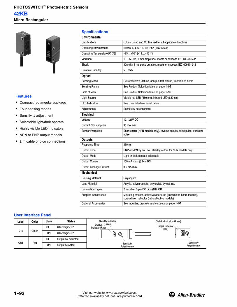
PHOTOSWITCHR Photoelectric Sensors
42KBMicro Rectangular
1--92 Visit our website: www.ab.com/catalogs.Preferred availability cat. nos. are printed in bold.
Features
S Compact rectangular package
S Four sensing modes
S Sensitivity adjustment
S Selectable light/dark operate
S Highly visible LED Indicators
S NPN or PNP output models
S 2 m cable or pico connections
SpecificationsEnvironmentalCertifications cULus Listed and CE Marked for all applicable directives
Operating Environment NEMA 1, 4, 6, 12, 13; IP67 (IEC 60529)
Operating Temperature [C (F)] --25…+55° (--13…+131°)
Vibration 10…55 Hz, 1 mm amplitude, meets or exceeds IEC 60947--5--2
Shock 30g with 1 ms pulse duration, meets or exceeds IEC 60947--5--2
Relative Humidity 5…85%
OpticalSensing Mode Retroreflective, diffuse, sharp cutoff diffuse, transmitted beam
Sensing Range See Product Selection table on page 1--95
Field of View See Product Selection table on page 1--95
Light Source Visible red LED (660 nm), infrared LED (880 nm)
LED Indicators See User Interface Panel below
Adjustments Sensitivity potentiometer
ElectricalVoltage 12…24V DC
Current Consumption 30 mA max
Sensor Protection Short circuit (NPN models only), reverse polarity, false pulse, transientnoise
OutputsResponse Time 350 μs
Output Type PNP or NPN by cat. no., stability output for NPN models only
Output Mode Light or dark operate selectable
Output Current 100 mA max @ 24V DC
Output Leakage Current 0.5 mA max
Mechanical
Housing Material Polyarylate
Lens Material Acrylic, polycarbonate, polyarylate by cat. no.
Connection Types 2 m cable, 3-pin DC pico (M8) QD
Supplied Accessories Mounting bracket, adhesive apertures (transmitted beam models),screwdriver, reflector (retroreflective models)
Optional Accessories See mounting brackets and cordsets on page 1--97
User Interface Panel
Label Color State Status
SensitivityPotentiometer
Stability Indicator(Green)Output
Indicator (Red)
SensitivityPotentiometer
Stability Indicator (Green)
Output Indicator(Red)
STB GreenOFF 0.8<margin<1.2
ON 0.8>margin>1.2
OUT RedOFF Output not activated
ON Output activated

PHOTOSWITCHR Photoelectric Sensors
42KBMicro Rectangular
1--93Visit our website: www.ab.com/catalogs.Preferred availability cat. nos. are printed in bold.
Wiring Diagrams
Black: Output
Orange: Stability Output
Brown: +12…24V DCCable
Blue: --DC
LoadLoad
Black: Output
Brown: +12…24V DCCable
Blue: --DC Load
Brown
Black
Blue
1
3
4
Brown
Black
Blue
1
3
4
Pico
CableNPN Output PNP Output
Quick-Disconnect
31
4
Note: Details regarding connection of Rockwell Automation Bulletin 42KB photoelectric sensors to Rockwell Automation ProgrammableControllers can be found in “PHOTOSWITCHR Photoelectric Sensors and Programmable Controller Interface Manual” onwww.ab.com/literature.
Approximate Dimensions [mm (in.)]
16(0.62)
OpticalAxis
7.5(0.29)
15(0.59)
Dia. 3.1 (0.12)2 Places
3(0.12)
L.O.
D.O.
3(0.12)
End View Sensors
21.8(0.86)
Dia. 3.2(0.13)
1.0(0.04)
3.2(0.13)
3(0.12)
2(0.08)
Side View Sensors
OpticalAxis
12.7(0.50)
Dia. 3.2(0.13)
Lens
L.O.
D.O.
15(0.59)
Lens
19(0.74)
16.4(0.65)25.4
(1.0)
30 (1.18)
10 (0.39)
10.3(0.40)

PHOTOSWITCHR Photoelectric Sensors
42KBMicro Rectangular
1--94 Visit our website: www.ab.com/catalogs.Preferred availability cat. nos. are printed in bold.
Typical Response Curve Beam PatternRetroreflective Standard Diffuse—70 mm
1
10
100
0.1(0.33)
1(3.28)
Distance to 92- 93Reflector [m (ft)]
OperatingMargin
0
--20
0
0
Distance [m (ft)]
Beam
Diameter—mm
10
20
--10
Typical Response Curve Beam Pattern
OperatingMargin
0 20(0.8)
40(1.6)
60(2.4)
Distance to White Target [mm (in.)]
1--6
--4
0
6
8
0
Beam
Diameter—mm
Distance [mm (in.)]
Standard Diffuse—200 mm Standard Diffuse—300 mm
1
10
100
OperatingMargin
0 50(2)
100(3.9)
150(5.9)
Distance to White Target [mm (in.)] Distance [mm (in.)]
Beam
Diameter—mm
--10--8
--20
4
810
01
10
100
Distance to White Target [mm (in.)]
OperatingMargin
Distance [mm (in.)]
Beam
Diameter—mm
0
10(32.8)
0.5(1.64)
1(3.28)
10
100
--2
4
6
2
--6--4
Standard Diffuse—400 mm
1
10
100
Distance to White Target [mm (in.)]
OperatingMargin
0--15
0
0
Distance [mm (in.)]
Beam
Diameter—mm
10
15
--10
100
--40
--30
30
40
2(6.56)
1.5(4.92)
2
--820(0.8)
40(1.6)
60(2.4)
200(7.87)
50(2)
100(3.9)
150(5.9)
200(7.87)
100(3.9)
200(7.87)
0 300(11.8)
100(3.9)
200(7.87)
300(11.8)
--10--8
--20
4
810
6
2
--6--4
300(11.8)
100(3.9)
400(15.7)
200(7.87)
5
--5
300(11.8)
100(3.9)
400(15.7)
200(7.87)

PHOTOSWITCHR Photoelectric Sensors
42KBMicro Rectangular
1--95Visit our website: www.ab.com/catalogs.Preferred availability cat. nos. are printed in bold.
Typical Response Curve Beam PatternSharp Cutoff Diffuse—30 mm Sharp Cutoff Diffuse—40 mm
1
10
100
10(0.39)
20(0.78)
Operating Distance [mm (in.)]
OperatingMargin
0
--20
0
0
Distance [mm (in.)]
Beam
Diameter—mm 10
20
--10
Typical Response Curve Beam Pattern
OperatingMargin
01
--2
--1
0
1
2
0
Beam
Diameter—mm
Distance [mm (in.)]
Transmitted Beam—1 m Transmitted Beam—7 m
1
10
100
OperatingMargin
0 0.1(0.32)
1(3.28)
Operating Distance [m (ft)] Distance [m (ft)]
Beam
Diameter—mm
--25--20
--50
10
2025
01
10
100
Operating Distance [m (ft)]
OperatingMargin
Distance [m (ft)]
Beam
Diameter—mm
0
30(1.18)
10
100
--3
3
0.2(0.6)
0.4(1.3)
0.6(1.9)
15
5
--15--10
1000
10000
Transmitted Beam—10 m
1
10
100
Operating Distance [m (ft)]
OperatingMargin
0
--20
0
0
Distance [m (ft)]
Beam
Diameter—mm
10
20
--10
10(0.39)
20(0.78)
30(1.18)
Operating Distance [mm (in.)]
10(0.39)
20(0.78)
30(1.18)
40(1.57)
10(0.39)
20(0.78)
30(1.18)
40(1.57)
1000
1(3.28)
0.8(2.6)
0 0.1(0.32)
1(3.28)
10(32.8)
--800
--600
0
200
600
800
400
--400
--200
1(3.28)
3(9.8)
5(16.4)
7(22.9)
1000
10000
1(3.28)
10(32.8)
30
--302
(6.5)4
(13.1)6
(19.6)8
(26.2)10(32.8)
Product Selection
Sensing ModeOperating VoltageSupply Current
SensingDistance
OutputEnergized
LEDSource
Output TypeCapacity
Response Time
End orSideView
ConnectionType Cat. No.
Objectto beSensed
Retroreflective
Field of View: 5_Emitter LED: Visible red
660 nm
12…24V DC ±10%20 mA
3 mm…2 m
(0.12 in…6.6 ft)
Light/DarkSelectable —
NPNOutput: 100 mAStability: 50 mA
350 μs
Side
2 m 500V cable 42KB--U2LNSN--A2
3-pin pico 42KB--U2LNSN--Y3
12…24V DC ±10%25 mA
PNPOutput: 100 mA
350 μs
2 m 500V cable 42KB--U2LPSN--A2
3-pin pico 42KB--U2LPSN--Y3
Refer to page 1--97 for cordsets and accessories.

PHOTOSWITCHR Photoelectric Sensors
42KBMicro Rectangular
1--96 Visit our website: www.ab.com/catalogs.Preferred availability cat. nos. are printed in bold.
Product Selection (continued)
Sensing ModeOperating VoltageSupply Current
SensingDistance[mm (in.)]
OutputEnergized
LEDSource
Output TypeCapacity
Response Time
End orSideView
ConnectionType Cat. No.
Objectto beSensed
Standard DiffuseField of View: 50 mm Infraredsensors: 20_; All others: 12_Emitter LED: See ProductSelection
12…24V DC ±10%25 mA
3…70(0.12…2.8)
Light/DarkSelectable
IR 950 nm
NPNOutput: 100 mA,Stability: 50 mA
350 μs
End2 m 500V cable 42KB--D1LNED--A2
3-pin pico 42KB--D1LNED--Y3
Side2 m 500V cable 42KB--D1LNSD--A2
3-pin pico 42KB--D1LNSD--Y3
12…24V DC ±10%28 mA
PNPOutput: 100 mA
350 μs
End2 m 500V cable 42KB--D1LPED--A2
3-pin pico 42KB--D1LPED--Y3
Side2 m 500V cable 42KB--D1LPSD--A2
3-pin pico 42KB--D1LPSD--Y3
12…24V DC ±10%22 mA
3…200(0.12…7.9) IR 900 nm
NPNOutput: 100 mA,Stability: 50 mA
350 μs
End
2 m 500V cable 42KB--D1LNEG--A2
3-pin pico 42KB--D1LNEG--Y3
12…24V DC ±10%25 mA
PNPOutput: 100 mA
350 μs
2 m 500V cable 42KB--D1LPEG--A2
3-pin pico 42KB--D1LPEG--Y3
12…24V DC ±10%20 mA
3…300(0.12…11.8)
Red 700nm
NPNOutput: 100 mA,Stability: 50 mA
350 μs
2 m 500V cable 42KB--D2LNEH--A2
3-pin pico 42KB--D2LNEH--Y3
12…24V DC ±10%25 mA
PNPOutput: 100 mA
350 μs
2 m 500V cable 42KB--D2LPEH--A2
3-pin pico 42KB--D2LPEH--Y3
12…24V DC ±10%22 mA
IR 900 nm
NPNOutput: 100 mA,Stability: 50 mA
350 μs
Side
2 m 500V cable 42KB--D1LNSH--A2
3-pin pico 42KB--D1LNSH--Y3
12…24V DC ±10%25 mA
PNPOutput: 100 mA
350 μs
2 m 500V cable 42KB--D1LPSH--A2
3-pin pico 42KB--D1LPSH--Y3
12…24V DC ±10%20 mA
3…400(0.12…15.8)
Red 700nm
NPNOutput: 100 mA,Stability: 50 mA
350 μs
2 m 500V cable 42KB--D2LNSG--A2
3-pin pico 42KB--D2LNSG--Y3
12…24V DC ±10%25 mA
PNPOutput: 100 mA
350 μs
2 m 500V cable 42KB--D2LPSG--A2
3-pin pico 42KB--D2LPSG--Y3
Objectto beSensed
Sharp Cutoff DiffuseField of View: Infraredsensors: 15_; Visible redsensors: 20_Emitter LED: Infrared 900 nmor Visible red 660 nm (SeeProduct Selection)
12…24V DC ±10%20 mA
3…30(0.12…1.2)
Light/DarkSelectable
Red 660nm NPN
Output: 100 mAStability: 50 mA
350 μs
Side
2 m 500V cable 42KB--S2LNSA--A2
3-pin pico 42KB--S2LNSA--Y3
12…24V DC ±10%22 mA
3…40(0.12…1.6) IR 900 nm
2 m 500V cable 42KB--S1LNSB--A2
3-pin pico 42KB--S1LNSB--Y3
12…24V DC ±10%25 mA
3…30(0.12…1.2)
Red 660nm PNP
Output: 100 mA350 μs
2 m 500V cable 42KB--S2LPSA--A2
3-pin pico 42KB--S2LPSA--Y3
3…40(0.12…1.6) IR 900 nm
2 m 500V cable 42KB--S1LPSB--A2
3-pin pico 42KB--S1LPSB--Y3
See page 1--93 for detailed dimensions.
Refer to page 1--97 for cordsets and accessories.

PHOTOSWITCHR Photoelectric Sensors
42KBMicro Rectangular
1--97Visit our website: www.ab.com/catalogs.Preferred availability cat. nos. are printed in bold.
Product Selection (continued)
Sensing ModeOperating VoltageSupply Current
SensingDistance
OutputEnergized
LEDSource
Output TypeCapacity
Response Time
End orSideView
ConnectionType Cat. No.
Objectto beSensed
Transmitted BeamField of View: 1 m sensors:50_; All others: 24_Emitter LED: Infrared 880 nmor Visible red 700 nm (SeeProduct Selection)
12…24V DC ±10%Source: 23 mAReceiver: 18 mA
3 mm…1 m(0.12 in…3.2 ft)
Light/DarkSelectable
IR 880 nmNPN
Output: 100 mA,Stability: 50 mA
350 μs
End2 m 500V cable 42KB--T1LNEL--A2
3-pin pico 42KB--T1LNEL--Y3
Side2 m 500V cable 42KB--T1LNSL--A2
3-pin pico 42KB--T1LNSL--Y3
3 mm…7 m(0.12 in…23 ft)
End2 m 500V cable 42KB--T1LNEQ--A2
3-pin pico 42KB--T1LNEQ--Y3
Side
2 m 500V cable 42KB--T1LNSQ--A2
3-pin pico 42KB--T1LNSQ--Y3
12…24V DC ±10%Source: 20 mAReceiver: 18 mA
3 mm…10 m
(0.12 in…32.8 ft)
Red 700nm
2 m 500V cable 42KB--T2LNSR--A2
3-pin pico 42KB--T2LNSR--Y3
12…24V DC ±10%Source: 23 mAReceiver: 21 mA
3 mm…1 m(0.12 in…3.2 ft)
IR 880 nmPNP
Output: 100 mA350 μs
End2 m 500V cable 42KB--T1LPEL--A2
3-pin pico 42KB--T1LPEL--Y3
Side2 m 500V cable 42KB--T1LPSL--A2
3-pin pico 42KB--T1LPSL--Y3
3 mm…7 m(0.12 in…23 ft)
End2 m 500V cable 42KB--T1LPEQ--A2
3-pin pico 42KB--T1LPEQ--Y3
Side2 m 500V cable 42KB--T1LPSQ--A2
3-pin pico 42KB--T1LPSQ--Y3
12…24V DC ±10%Source: 20 mAReceiver: 21 mA
3 mm…10 m
(0.12 in…32.8 ft)
Red 700nm
PNPOutput: 100 mA
350 μsSide
2 m 500V cable 42KB--T2LPSR--A2
3-pin pico 42KB--T2LPSR--Y3
See page 1--93 for detailed dimensions.Adhesive 1 mm apertures are included with these sensors.Optional metal apertures are available for these sensors under Accessories .Both a light source (emitter) and receiver are included in the package. To identify the light source, replace the “T” in the cat. no. with “E.” To identify thereceiver, replace the “T” in the cat. no. with “R.” Example: 42KB--T2KNHK--A2 contains one 42KB--E2KNHK--A2 light source and one 42KB--R2KNHK--A2receiver. Light sources and receivers are not available separately.
Maximum Operating Distance with Apertures
Aperture Cat. No.
Sensor Cat. No.61- 6726 61- 6727 61- 6728 61- 6729
100 mm (3.93 in.) 300 mm (11.8 in.) 400 mm (15.7 in.) 300 mm (11.8 in.) 42KB--T1LNSL--A2 42KB--T1LPSL--A2
400 mm (1.57 in.) 1 m (39.3 in.) 3 m (9.8 ft) 2 m (6.56 ft) 42KB--T2LNSR--A2 42KB--T2LPSR--A2
300 mm (11.8 in.) 1 m (39.3 in.) 2.5 m (8.2 ft) 1.7 m (5.6 ft) 42KB--T1LNSQ--A2 42KB--T1LPSQ--A2
Cordsets and Accessories
Description Cat. No. Description Cat. No.
Pico QD Cordset, 3-pin 2 m 889P--F3AB--2 Aperture, 2 mm (10 pcs) 61--6727
End View Bracket (included) 60--2632 Aperture, 3 mm (10 pcs) 61--6728
Side View Bracket (included) 60--2633 Aperture, 1 x 5 mm (10 pcs) 61--6729
Aperture, 1 mm (10 pcs) 61--6726 Reflectors (included) 92--93

PHOTOSWITCHR Photoelectric Sensors
42KCMiniature Rectangular
1--98 Visit our website: www.ab.com/catalogs.Preferred availability cat. nos. are printed in bold.
Features
S Compact rectangular package
S Three sensing modes
S Diagnostic output
S Sensitivity adjustment
S Selectable light/dark operate
S Highly visible LED indicators
S NPN or PNP output models
S 2 m cable or pico connections
SpecificationsEnvironmentalCertifications UL Listed, CSA Certified, and CE Marked for all applicable directives
Operating Environment NEMA 1, 4X, 6P, 12, 13; IP67
Operating Temperature [C (F)] --25…+55° (--13…+131°)
Vibration 10…55 Hz, 1 mm amplitude, meets or exceeds IEC 60947--5--2
Shock 30 g with 1 ms pulse duration, meets or exceeds IEC 60947--5--2
Relative Humidity 5…85%
OpticalSensing Mode Polarized retroreflective, diffuse, transmitted beam
Sensing Range See Product Selection table on page 1--101
Field of View See Product Selection table on page 1--101
Light Source Visible red LED (700 nm)
LED Indicators See User Interface Panel below
Electrical
Voltage 12…24V DC
Current Consumption 35 mA max
Sensor Protection Short circuit (NPN models only), reverse polarity, false pulse, transientnoise
Outputs
Response Time 350 μS
Output Type PNP or NPN by cat. no.
Output Mode Light or dark operate selectable
Output Current 100 mA max @ 24V DC
Output Leakage Current 0.5 mA max
Mechanical
Housing Material Polyarylate
Lens Material Acrylic
Connection Types 2 m cable, 4-pin DC pico (M8) QD
Supplied Accessories Mounting bracket, screwdriver, reflector (retroreflective models)
Optional Accessories See mounting brackets and cordsets on page 1--101
User Interface Panel
Label Color State Status
Stability Indicator(Green)
Light Operate/DarkOperate Switch
Stability Indicator(Green)
SensitivityPotentiometer
OutputIndicator(Red)
Output Indicator(Red)
Light Operate/DarkOperate Switch
SensitivityPotentiometer
STB GreenOFF 0.8<margin<1.2
ON 0.8>margin>1.2
OUT RedOFF Output not activated
ON Output activated
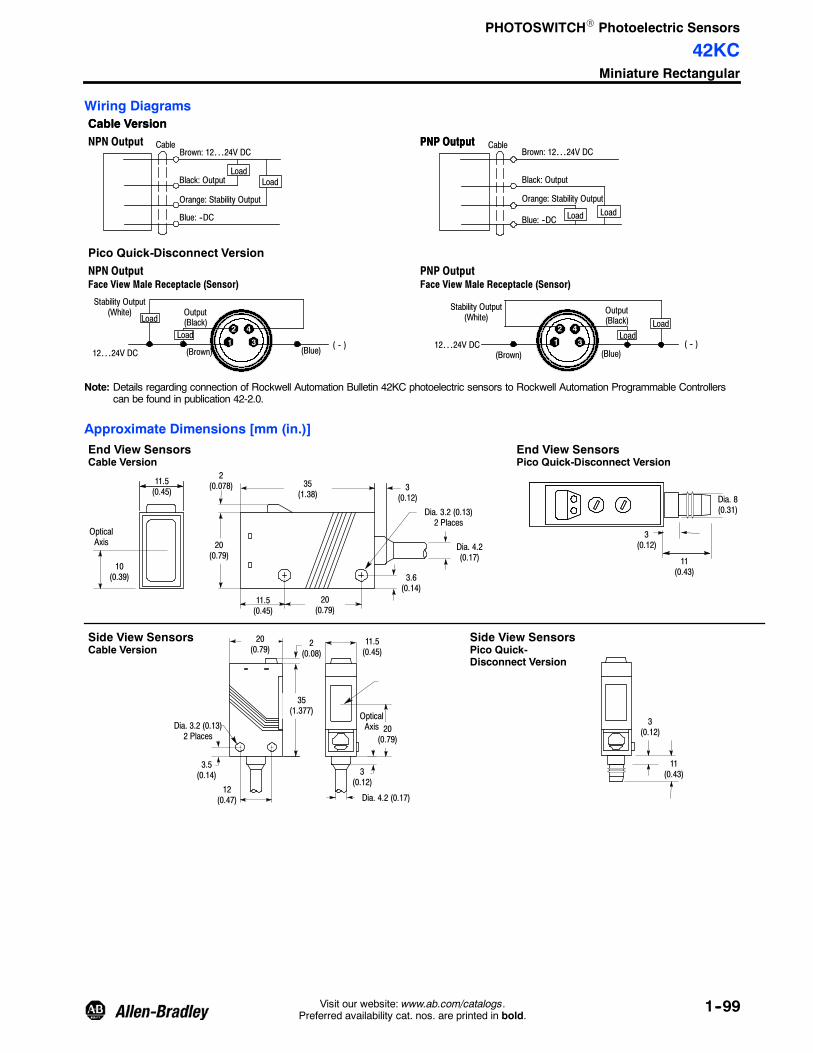
PHOTOSWITCHR Photoelectric Sensors
42KCMiniature Rectangular
1--99Visit our website: www.ab.com/catalogs.Preferred availability cat. nos. are printed in bold.
Wiring Diagrams
NPN Output PNP OutputCable Version
Black: Output
Brown: 12…24V DCCable
Blue: --DC
Orange: Stability Output
LoadBlack: Output
Brown: 12…24V DCCable
Blue: --DC
Orange: Stability Output
Load
Load Load
PNP OutputCable Version
NPN OutputFace View Male Receptacle (Sensor)
PNP OutputFace View Male Receptacle (Sensor)
Pico Quick-Disconnect Version
2
1 3
4 2
1 3
4Load
12…24V DC (Brown)
Stability Output(White) Output
(Black)
(Blue)( -- ) 12…24V DC
(Brown)
Stability Output(White)
Output(Black)
(Blue)( -- )
Load
LoadLoad
Note: Details regarding connection of Rockwell Automation Bulletin 42KC photoelectric sensors to Rockwell Automation Programmable Controllerscan be found in publication 42-2.0.
Approximate Dimensions [mm (in.)]
3.6(0.14)
2(0.078)
20(0.79)
11.5(0.45)
20(0.79)
Dia. 3.2 (0.13)2 Places
11.5(0.45)
35(1.38)
3(0.12)
End View SensorsCable Version
10(0.39)
OpticalAxis Dia. 4.2
(0.17)
End View SensorsPico Quick-Disconnect Version
Dia. 8(0.31)
3(0.12)
11(0.43)
12(0.47)
11.5(0.45)
20(0.79)
35(1.377)
2(0.08)
Dia. 3.2 (0.13)2 Places
3.5(0.14)
Dia. 4.2 (0.17)
3(0.12)
Side View SensorsCable Version
20(0.79)
OpticalAxis
Side View SensorsPico Quick-Disconnect Version
3(0.12)
11(0.43)

PHOTOSWITCHR Photoelectric Sensors
42KCMiniature Rectangular
1--100 Visit our website: www.ab.com/catalogs.Preferred availability cat. nos. are printed in bold.
Typical Response Curve Beam PatternPolarized Retroreflective Standard Diffuse
1
10
100
Distance to 92- 93 Reflector [m ( ft)]
OperatingMargin
0
--20
0
0
Distance [m ( ft)]
Beam
Diameter—mm 40
20
--40
Typical Response Curve Beam Pattern
OperatingMargin
1
--2
--1
0
1
2
0
Beam
Diameter—mm
Distance [mm (in.)]
Transmitted Beam
1
10
100
OperatingMargin
0.1(0.3)
1(3.28)
Operating Distance [m ( ft)] Distance [m ( ft)]
Beam
Diameter—mm
--150
--100
0
100
150
10
100
--3
3
50
--50
Distance to White Target [mm (in.)]
10(0.39)
100(3.93)
1000(39.3)
1000
1(3.28)
10(32.8)
80
60
--60
--800.2(0.6)
0.6(1.9)
1(3.28)
1.4(4.59)
0.1(0.003)
1(0.03)
400(15.7)
100(3.93)
500(19.6)
300(11.8)
200(7.87)
10(32.8)
0 2(6.5)
4(13.1)
6(19.6)
7(22.9)
1(3.28)
3(10)
5(16.4)

PHOTOSWITCHR Photoelectric Sensors
42KCMiniature Rectangular
1--101Visit our website: www.ab.com/catalogs.Preferred availability cat. nos. are printed in bold.
Product Selection
Sensing ModeOperating VoltageSupply Current
SensingDistance
OutputEnergized
Output TypeCapacity
Response Time
End orSideView
ConnectionType Cat. No.
Objectto beSensed
Polarized Retroreflective
Field of View: 8_Emitter LED: Visible red 700 nm
12…24V DC ±10%30 mA
50 mm…1.5 m(1.9 in…4.9 ft)
Light/DarkSelectable
NPNOutput: 100 mAStability: 50 mA
0.5 ms
End2 m 500V cable 42KC--P2LNEM--A2
4-pin pico 42KC--P2LNEM--P4
Side2 m 500V cable 42KC--P2LNSM--A2
4-pin pico 42KC--P2LNSM--P4
12…24V DC ±10%35 mA
PNPOutput: 100 mAStability: 50 mA
0.5 ms
End2 m 500V cable 42KC--P2LPEM--A2
4-pin pico 42KC--P2LPEM--P4
Side2 m 500V cable 42KC--P2LPSM--A2
4-pin pico 42KC--P2LPSM--P4
5V DC10%25 mA
NPNOutput: 100 mAStability: 50 mA
0.5 ms
Side2 m 500V cable 42KC--P2YNSM--A2
4-pin pico 42KC--P2YNSM--P4
Objectto beSensed
Standard Diffuse
Field of View: 7_Emitter LED: Visible red 700 nm
12…24V DC ±10%30 mA
3…500 mm(0.12…19.7 in.)
Light/DarkSelectable
NPNOutput: 100 mAStability: 50 mA
0.5 ms
End2 m 500V cable 42KC--D2LNEK--A2
4-pin pico 42KC--D2LNEK--P4
Side2 m 500V cable 42KC--D2LNSK--A2
4-pin pico 42KC--D2LNSK--P4
12…24V DC ±10%35 mA
PNPOutput: 100 mAStability: 50 mA
0.5 ms
End2 m 500V cable 42KC--D2LPEK--A2
4-pin pico 42KC--D2LPEK--P4
Side2 m 500V cable 42KC--D2LPSK--A2
4-pin pico 42KC--D2LPSK--P4
Objectto beSensed
Transmitted Beam
Field of View: 10_Emitter LED: Visible red 700 nm
12…24V DC ±10%Source: 20 mAReceiver: 20 mA
50 mm…7 m
(1.9 in…23.0 ft)
Light/DarkSelectable
NPNOutput: 100 mAStability: 50 mA
0.5 ms
End2 m 500V cable 42KC--T2LNGP--A2
4-pin pico 42KC--T2LNGP--P4
Side2 m 500V cable 42KC--T2LNTP--A2
4-pin pico 42KC--T2LNTP--P4
12…24V DC ±10%Source: 20 mAReceiver: 25 mA
PNPOutput: 100 mAStability: 50 mA
0.5 ms
End2 m 500V cable 42KC--T2LPGP--A2
4-pin pico 42KC--T2LPGP--P4
Side2 m 500V cable 42KC--T2LPTP--A2
4-pin pico 42KC--T2LPTP--P4
See page 1--99 for detailed dimensions.
Both a light source (emitter) and receiver are included in the package. To identify the light source, replace the “T” in the cat. no. with “E.” To identify thereceiver, replace the “T” in the cat. no. with “R.” Example: 42KC--T2LNGP--A2 contains one 42KC--E2LNGP--A2 light source and one 42KC--R2LNGP--A2receiver. Light sources and receivers are not available separately.
Cordsets and Accessories
Description Cat. No.
Pico QD Cordset, 4-pin 2 m 889P--F4AB--2
End View Bracket 60--2634
Side View Bracket 60--2635
Reflectors (included) 92--93

PHOTOSWITCHR Photoelectric Sensors
Series 7000Miniature Rectangular
1--102 Visit our website: www.ab.com/catalogs.Preferred availability cat. nos. are printed in bold.
Obsolet
e

PHOTOSWITCHR Photoelectric Sensors
Series 7000Miniature Rectangular
1--103Visit our website: www.ab.com/catalogs.Preferred availability cat. nos. are printed in bold.
Obsolet
e

PHOTOSWITCHR Photoelectric Sensors
Series 7000Miniature Rectangular
1--104 Visit our website: www.ab.com/catalogs.Preferred availability cat. nos. are printed in bold.
Obsolet
e

PHOTOSWITCHR Photoelectric Sensors
Series 7000Miniature Rectangular
1--105Visit our website: www.ab.com/catalogs.Preferred availability cat. nos. are printed in bold.
Obsolet
e

PHOTOSWITCHR Photoelectric Sensors
Series 7000Miniature Rectangular
1--106 Visit our website: www.ab.com/catalogs.Preferred availability cat. nos. are printed in bold.
Obsolet
e

PHOTOSWITCHR Photoelectric Sensors
Series 7000Miniature Rectangular
1--107Visit our website: www.ab.com/catalogs.Preferred availability cat. nos. are printed in bold.
Obsolet
e

PHOTOSWITCHR Photoelectric Sensors
LaserSightt RightSightt18 mm Right Angle
1--108 Visit our website: www.ab.com/catalogs.Preferred availability cat. nos. are printed in bold.
Features
S Class 1 eye safe visible laser
S Models with teach function
S Compact right angle housing
S Flexible 18 mm mounting options
S 360_ visible LED indicators
S Reverse polarity protection
S Short-circuit protected outputs
S 1 ms response time
S False pulse protection
S NPN and PNP outputs
SpecificationsEnvironmentalCertifications UL Listed, CSA Certified, and CE Marked for all applicable directives
Operating Environment IP54 (IEC 60529)
Operating Temperature [C (F)] --10…+40° (14…+104°)
Vibration 10…55 Hz, 1 mm amplitude, meets or exceeds IEC 60947--5--2
Shock 30 g with 1 ms pulse duration, meets or exceeds IEC 60947--5--2
Relative Humidity 5…95% (noncondensing)
OpticalSensing Modes Polarized retroreflective, diffuse, transmitted beam
Sensing Range See Product Selection table on page 1--111
Field of View See Product Selection table on page 1--111
Light Source Class 1 visible red laser (660 nm)
LED Indicators See User Interface below
Electrical
Voltage 24V DC ± 10%
Current Consumption 30 mA max
Sensor Protection Overload, short circuit, reverse polarity, false pulse
Outputs
Response Time 1 ms (4 ms for transmitted beam)
Output Type PNP and NPN
Output Mode Light or dark operate by cat. no.
Output Current 100 mA @ 24V DC max
Output Leakage Current 0.1 mA max
Mechanical
Housing Material Mindel
Lens Material Acrylic
Connection Types 2 m cable (24 AWG), 4-pin DC micro (M12) QD
Supplied Accessories 18 mm mounting nut
Optional Accessories See mounting brackets, reflectors, and cordsets on page 1--111
User Interface
No Adjustment Manual Adjustment Teach
ButtonSingleTurn Knob
LED Color StateStatus—Teachable andAdjustable Versions
Status—Transmitted BeamReceiver
Yellow
OFF Output de-energized
ON Output energized
Flashing NA Output SCP active
Orange
OFF Normal operation Margin < 2.5x
ON Teach mode active Margin > 2.5x
Flashing Output SCP activeTeach mode active
NA
Green
OFF Sensor not powered Sensor not powered, outputon, or SCP active
ON Sensor powered
Flashing Unstable margin condition(0.7x…2.0x) or output SCP active
NA
Note: For laser models, output and margin LEDs flash simultaneously when SCP active.

PHOTOSWITCHR Photoelectric Sensors
LaserSightt RightSightt18 mm Right Angle
1--109Visit our website: www.ab.com/catalogs.Preferred availability cat. nos. are printed in bold.
Wiring Diagrams
+
--
Output VersionsBrown
Blue
WhiteBlack
+
--
1243
Cable Quick- Disconnect
BrownWhiteBlackBlue
DC Micro
LoadLoad
LoadLoad
T T
Brown
Blue
+
--
1
3
+
--
Cable Quick- Disconnect
Brown
Blue
DC Micro
Transmitted Beam Source
32
41 3
2
41
For Rockwell Automation programmable controller compatible interface, refer to publication 42--2.0.All wire colors on quick-disconnect models refer to Rockwell Automation 889D cordsets.
Approximate Dimensions [mm (in.)]Teach Function Models Adjustable Models
14.48 (0.57)
10(0.40)
26.5(1.04)
27(1.06)
16.5(0.65)
19(0.75)
20.5(0.81)
4(0.16)
9.6(0.38)
3.6 (0.145) dia.Clearance for #6--32 Screw(2 places)
M18 X 1.0Thread
34.5 (1.36)
32.7(1.29)
49.7(1.96)
70.8(2.8)
152.4(6)
2m (6.56ft)cable
MicroQuick--Disconnect
14.48 (0.57)
10(0.40)
26.5(1.04)
27(1.06)
16.5(0.65)
19(0.75)
20.5(0.81)
4(0.16)
9.6(0.38)
3.6 (0.145) dia.Clearance for#6--32 Screw(2 places)
M18 X 1.0Thread
34.5 (1.36)
32.7(1.29)
49.7(1.96)
69(2.72)
152.4(6)
2m (6.56ft)cable
MicroQuick--Disconnect
Note: All sensors supplied with one M18 mounting nut (Cat. No. 75012--097--01).

PHOTOSWITCHR Photoelectric Sensors
LaserSightt RightSightt18 mm Right Angle
1--110 Visit our website: www.ab.com/catalogs.Preferred availability cat. nos. are printed in bold.
Typical Response CurveStandard Diffuse—Beam Pattern
Polarized Retroreflective—Beam Pattern
0 100(3.9)
Beam
Diameter(mm)
Distance [mm (in.)]
--2
0
1
200(7.8)
400(15.7)
0 20(65.6)
Distance [m (ft)]
--6
0
6
5(16.4)
100(328)
1(3.3)
Distance [m (ft)]
1000
100
10
110
(32.8)
Transmitted Beam—Margin
1(0.04)
100(3.94)
OperatingMargin
Distance [mm (in.)]
100
10
110
(0.39)1000(39.4)
Standard Diffuse—Margin
1(3.3)
100(328)
Distance [m (ft)]
100
10
110
(32.8)0.01(0.03)
Polarized Retroreflective—Margin
0.1(0.33)
92--118 92--39
--1
2
300(11.8)
--4
--2
2
4
10(32.8)
15(49.2)
Beam
Diameter(mm)
OperatingMargin
OperatingMargin
Typical Spot Size
Model Distance 300 mm 15 m 40 m
Polarized Retroreflective
Spot Size
2 x 3.5 16 x 20 mm —
Diffuse 2 x 3.5 — —
Transmitted Beam 2 x 3.5 16 x 20 mm 50 mm x 70 m
Actual spot size may be smaller.

PHOTOSWITCHR Photoelectric Sensors
LaserSightt RightSightt18 mm Right Angle
1--111Visit our website: www.ab.com/catalogs.Preferred availability cat. nos. are printed in bold.
Product Selection
Sensing ModeSupplyVoltage
SensingDistance[mm (in.)]
AdjustmentType
OutputEnergized
Output Type/Rating/ResponseTime
ConnectionType Cat. No.
Objectto beSensed
Polarized Retroreflective
24V DC ±10%
0.05…15 m(0.16…49.2 ft) Teach Button Dark Operate
NPN and PNP/100 mA/1 ms max.
2 m 300V cable 42EF--P8KBC--A2
4-pin DC micro QD 42EF--P8KBC--F4
Objectto beSensed
Standard Diffuse
300 (11.8) Single-TurnKnob Light Operate
NPN and PNP/100 mA/1 ms max.
2 m 300V cable 42EF--D8JBA--A2
4-pin DC micro QD 42EF--D8JBA--F4
300 (11.8) Teach Button Light OperateNPN and PNP/100 mA/1 ms max.
2 m 300V cable 42EF--D8JBC--A2
4-pin DC micro QD 42EF--D8JBC--F4
Objectto beSensed
Transmitted Beam
Light Source NA NA NA2 m 300V cable 42EF--E8EZB--A2
4-pin DC micro QD 42EF--E8EZB--F4
0.015…40 m(0.05…131.2 ft) No Adjustment Dark Operate
NPN and PNP/100 mA/4 ms max.
2 m 300V cable 42EF--R7KBB--A2
4-pin DC micro QD 42EF--R7KBB--F4
Cordsets and Accessories
Description Cat. No.
2 m (6.5 ft) 4-pin, DC MicroQD Cordset
889D--F4AC--2
Microcube reflector forpolarized retroreflective laser
sensors92--118
Swivel/Tilt bracket allows ±10°vertical and 360° rotation
adjustment60--2649
Right Angle Bracket 60--2677

PHOTOSWITCHR Photoelectric Sensors
LaserSightt 9000Class II Laser Sensor
1--112 Visit our website: www.ab.com/catalogs.Preferred availability cat. nos. are printed in bold.
Features
S Class II laser light source
S Long range polarized retroreflectiveand transmitted beam sensingmodes
S Visible red beam for easyalignment
S Robust 30 mm housing
S Both NPN and PNP outputs (DC)
S SPDT relay output (AC)
S Selectable light/dark operate
S Micro, mini QD, 2 m cableconnections
SpecificationsEnvironmentalCertifications UL Listed, CSA Approved, CE Marked for all applicable directives
Operating Environment NEMA 3,4X,6P,12,13; IP67(IEC529) 1200 psi (8270 kPa) washdown,IP69K
Operating Temperature [C (F)] --10…+40° (14…+104°)
Vibration 10…55 Hz, 1 mm amplitude, meets or exceeds IEC 60947--5--2
Shock 30 g with 1 ms pulse duration, meets or exceeds IEC 60947--5--2
Relative Humidity 5…95%
Ambient Light Immunity Incandescent light 5000 lux
Optical
Sensing Modes Polarized retroreflective and transmitted beam
Sensing Range See Product Selection table on page 1--114
Field of View See Product Selection table on page 1--114
Light Source Class 2 laser
LED Indicators See User Interface Panel below
Adjustments Single-turn potentiometer for sensitivity
Electrical
Voltage 10…30V DC , 110…132V AC models, 10…264 V AC/DC models
Current Consumption 45 mA max (DC models), 10 mA max (AC/DC models), 70 mA max ACmodels
Sensor Protection Overload (DC only), short circuit (DC only), reverse polarity, false pulse
Outputs
Response Time See Product Selection table on page 1--114
Output Type PNP and NPN (DC only), EM relay
Output Mode Light operate or dark operate selectable
Output Current See Product Selection table on page 1--114
Output Leakage Current 10 μA max
Mechanical
Housing Material ValoxR
Lens Material Acrylic
Cover Material Neoprene
Connection Types 2 m 300V AC cable, 4-pin DC micro QD, 4-pin DC mini QD, 5-pin DCmicro QD
Supplied Accessories 129--130 mounting kit
Optional Accessories See mounting brackets, reflectors, and cordsets on page 1--114
User Interface Panel
Label Color State Status
Yellow PowerOn Indicator
Green OutputEnergized Indicator
Red Margin/SCPIndicator
SensitivityAdjustment
Light/DarkOperate Switch
Margin/SCP Red
OFF Margin < 2.5
ON Margin > 2.5
Flashing Output SCP active
Output GreenOFF Output not activated
ON Output activated
Power YellowOFF Sensor not powered
ON Sensor powered

PHOTOSWITCHR Photoelectric Sensors
LaserSightt 9000Class II Laser Sensor
1--113Visit our website: www.ab.com/catalogs.Preferred availability cat. nos. are printed in bold.
Wiring Diagrams
12 NPN4 PNP3
4-pin DC Micro QD Model: 42GR_- 9_L0-QD12 NPN4 PNP3
Cable Model: 42GR_- 9_L0Brown
White: NPNBlack: PNP
Blue
( + )
( -- )
4-pin DC Mini QD Model: 42GR_- 9_L0-QD1
Load
Load
Load
Load
( + )
( -- )
Load
Load
( + )
( -- )
DC Models
AC Models5-pin AC Mini QD Model: 42GR_- 9_L2-QDCable Model: 42GR_- 9_L2
Brown
Orange (C)
Black (NO)
Blue
White (NC)
4
3 (C)
1 (NO)
2
5 (NC)~
~
~
~
43
1
2
Transmitted Beam Source
T T T4
AC/DC Mini QD Model: 42GRL- 90L2-QDCable Model: 42GRL- 90L0
Brown
Blue
( + ) ~
( -- ) ~
31
2
Not UsedNot Used
DC Micro QD Model: 42GRL- 90L0-QD
21
4
3
Not UsedNot Used
( + ) ~
( -- ) ~
( + ) ~
( -- ) ~
43
1
2
Approximate Dimensions [mm (in.)]
41.91(1.650)
5.46(0.215)
27.05(1.065)
40.00(1.575)
32.66 (1.286)
69.85(2.750)
74.93(2.950) Ref
55.62(2.190)
16.76 (0.660)
31.75(1.250)
M30 X 1.5ExternalThread
1/2 in. NPSMInternal Thread 24.69
(0.970)
30.35(1.195)
15.87(0.625)
47.75(1.880)
42.41(1.670)
20.96(0.825)
7.62 (0.300)
15.24(0.600)
5.21 (0.205) X8.13 (0.320)Slot, 2 PLCS
Cable Version
Cable Length2 m (6.5 ft)
6.5 (0.255/0.245)Dia.
All Versions
103.63(4.080)
Max. Travel
M5 x 0.8 x 53Combination
Screws and Nuts(Supplied)
Hardware Kit(#129--130supplied)
Micro Style M12 x 11 Keyway
Thread Size
M12 x 11 Keyway
7/8--16 UN1 Keyway
Micro Style
Mini Style13.97 (0.550) 17.78 (0.700)
Micro Style Mini StyleConnector Version
7/8--16 UN1 KeywayMini Style

PHOTOSWITCHR Photoelectric Sensors
LaserSightt 9000Class II Laser Sensor
1--114 Visit our website: www.ab.com/catalogs.Preferred availability cat. nos. are printed in bold.
Typical Response CurvePolarized Retroreflective Transmitted Beam
Distance [m ( ft)]
OperatingMargin
OperatingMargin
Distance [m ( ft)]
100
10
10.3(1)
3(10)
30(100)
300(1000)
1
10
100
1000
10000
3(10)
30(100)
300(1000)
Product Selection
Sensing ModeOperating VoltageSupply Current
SensingDistance
OutputEnergized
Output Type/Capacity
Response TimeConnection
Type Cat. No.
Objectto beSensed
Polarized Retroreflective
Spot Size: 19 mm (3/4 in.) @ 40 m (130 ft)Emitter LED: Visible Laser, 650 nm
10…30V DC45 mA
0.3…40 m(1…130 ft)
SelectableLight/DarkOperate
PNP/250 mANPN/250 mA500 ms
2 m 300V cable 42GRU--92L0
4-pin DC micro 42GRU- 92L0-QD
4-pin DC mini 42GRU--92L0--QD1
110…132V AC70 mA
SPDT EM Relay2 A/132V AC1 A/150V DC
15 ms
2 m 300V cable 42GRU--92L2
5-pin mini 42GRU- 92L2-QD
Objectto beSensed
Transmitted Beam
Emitter LED: Visible Laser, 650 nm
10…264V AC/DC10 mA
300 m (1000 ft) NALight Source
2 m 300V cable 42GRL--90L0
4-pin micro 42GRL--90L0--QD
4-pin mini 42GRL- 90L2-QD
10…40V DC25 mA
5…300 m(16…1000 ft)
SelectableLight/DarkOperate
PNP/250 mANPN/250 mA5 ms max.
2 m 300V cable 42GRR--90L0
4-pin micro 42GRR--90L0--QD
4-pin mini 42GRR--90L0--QD1
70…264V AC/DC10 mA
SPDT EM Relay2 A/132V AC1 A/264V AC1 A/150V DC
23 ms
2 m 300V cable 42GRR--90L2
5-pin mini 42GRR- 90L2-QD
Temperature rating --10…+40_C for 24V DC operation. Reduce by 5_C for 120V AC and 10_C for 220V AC operation.
Cordsets and Accessories
Description Cat. No.
1.8 m (6 ft) 4-pin mini QD cordset 889N--F4AF--6F
1.8 m (6 ft) 5-pin mini QD cordset 889N--F5AF--6F
2 m (6.5 ft) 4-pin DC micro QD cordset 889D--F4AC--2
Tilt/Swivel Bracket 60--2439
Microcube reflector 92--118

PHOTOSWITCHR Photoelectric Sensors
42CM LaserSightt18 mm Metal Cylindrical, Class 1 Laser Sensor
1--115Visit our website: www.ab.com/catalogs.Preferred availability cat. nos. are printed in bold.
Features
S Class 1 laser
S Small spot size—0.1 mm @100 mm sensing distance
S Metal housing for heavy dutyindustrial applications
S 18 mm industry standard package
S Three sensing modes
S 30V DC operation
S NPN or PNP outputs
S Fast response time—less than0.7 ms
S 2 m cable or micro QD connector
SpecificationsEnvironmentalCertifications cULus and CE Marked for all applicable directives
Operating Environment IP67
Operating Temperature [C (F)] --10…+55° (+14…+131°)
Vibration 10…55 Hz, 1 mm amplitude, meets or exceeds IEC 60068--2--6
Shock 30 g with 1 ms pulse duration, meets or exceeds IEC 60068--2--27
Relative Humidity 15…95%
Ambient Light Immunity Incandescent light 5000 lux
Optical
Sensing Modes Polarized retroreflective, diffuse, and transmitted beam
Sensing Range See Product Selection table on page 1--118
Light Source Class 1 laser 650 nm
LED Indicators See User Interface Panel below
Adjustments Sensitivity potentiometer or teach button
ElectricalVoltage 10…30V DC
Current Consumption 25 mA max
Sensor Protection Reverse polarity, overload, short circuit
OutputsResponse Time 0.5 ms (transmitted beam), 0.7 ms (diffuse, polarized retroreflective)
Output Type PNP or NPN by cat. no.
Output Mode Complementary light or dark operate
Output Current 100 mA
Output Leakage Current 10 μA max
MechanicalHousing Material Nickel-plated brass
Lens Material Glass
Connection Types 2 m cable, 4-pin DC micro (M12) QD
Supplied Accessories 18 mm fastening nuts (871C--N3)
Optional Accessories See mounting brackets, reflectors, and cordsets on page 1--118
User Interface PanelLEDColor State Status LO Output DO Output
Yellow
OFF Dark condition OFF ON LED
Sensitivity Adjustment or Teach Button
Flashing Light condition (excess gain < 2) ON OFF
ON Light condition (excess gain > 2) ON OFF
Green ON Power On — —
Transmitted beam receivers do not have a “Flashing” (low margin) state.

PHOTOSWITCHR Photoelectric Sensors
42CM LaserSightt18 mm Metal Cylindrical, Class 1 Laser Sensor
1--116 Visit our website: www.ab.com/catalogs.Preferred availability cat. nos. are printed in bold.
Wiring Diagrams
Diffuse
Brown
Blue
White
Black
12
4
3Load
+
--
Cable Quick-Disconnect Cable
PNP Output
Load
LO
DOBrown
Blue
White
Black LoadLoad
LO
DO +
--
Brown
Blue
WhiteBlack Load
+
--
Load
LO
DO12
4
3
Quick-DisconnectBrown
Blue
White
Black LoadLoad
LO
DO +
--
Face View MaleReceptacle (Sensor)
DC Micro
NPN Output
32
41
Transmitted Beam, Polarized Retroreflective
NPN Output PNP Output
Brown
Blue
White
Black
12
4
3Load
+
--
Cable Quick-Disconnect
LoadLO
DO
Brown
Blue
White
Black LoadLoadLO
DO
+
--
Brown
Blue
White
Black
12
4
3Load
+
--
Cable Quick-Disconnect
LoadLO
DO
Brown
Blue
White
Black LoadLoadLO
DO
+
--
Laser Transmitted Beam Emitter (Standard LED)
Brown
Blue
+
--
1
3
Brown
Blue
+
--
Cable Quick-Disconnect
Black 2 White
Black open circuit to enable laser. Tie black to blue/V-- to disable laser.Pin 2/white open circuit to enable laser. Tie pin 2/white to blue/V-- to disable laser.
Approximate Dimensions [mm (in.)]Dimension Laser Receiver [mm (in.)] Other Laser Models [mm (in.)]
A 42.7 (1.68) 57.5 (2.26)
B 82.8 (3.26) 97.7 (3.85)
19.2(0.69)
A
LED
M18x1
6(0.24)
16.4(0.65)Dia.
M12x1
14(0.55)
19.2(0.69)
A
B
6(0.24)
M18x1
LED18 mm Mounting Nuts (supplied with sensor)
Sensitivity Adjustment or Teach Button
4.7 (0.19)Dia.

PHOTOSWITCHR Photoelectric Sensors
42CM LaserSightt18 mm Metal Cylindrical, Class 1 Laser Sensor
1--117Visit our website: www.ab.com/catalogs.Preferred availability cat. nos. are printed in bold.
Typical Response Curve
Distance [mm (in.)]
Diffuse
OperatingMargin
01
100(3.9)
200(7.8)
300(11.8)
400(15.7)
10
100
Distance [m (ft)]
OperatingMargin
1
100
10000
1000
10
Transmitted Beam
Grey Paper18%
White Paper90%
0 10(33)
20(66)
30(78)
40(131)
50(164)
Laser Polarized Retroreflective
92--118ReflectorO
peratingMargin
0 10(33)
20(66)
30(78)
40(131)
100
1
10
Distance [m (ft)]
Minimum Detectable Object
Distance [mm (in.)]
0
10.0(0.4)
0.0
8.0(0.32)
200(7.8)
100(3.93)
300(11.8)
Standard Diffuse
Minimum
DetectableObject[mm(in.)]
6.0(0.24)
2.0(0.08)
4.0(0.16)
400(15.7)
Polarized Retroreflective
Minimum
DetectableObject[mm(in.)]
Distance [m (ft)]
20(0.8)
10(0.4)
0 10(33)
20(66)
30(98)
0

PHOTOSWITCHR Photoelectric Sensors
42CM LaserSightt18 mm Metal Cylindrical, Class 1 Laser Sensor
1--118 Visit our website: www.ab.com/catalogs.Preferred availability cat. nos. are printed in bold.
Product Selection
Sensing Mode
OperatingVoltageSupplyCurrent
SensingDistance
@ 2X MarginOutput
Energized
Output TypeCapacity
Response TimeConnection
Type Cat. No.
Objectto beSensed
Standard Diffuse
Emitter: Class 1—Visible laser 650 nm
10…30V DC25 mA
3…300 mm(0.12…11.8 in.)(Teachable)
L.O./D.O.Complementary
NPN100 mA0.7 ms
2 m 300V cable 42CM--D8MNA--A2
4-pin DC micro 42CM--D8MNA--D4
PNP100 mA0.7 ms
2 m 300V cable 42CM--D8MPA--A2
4-pin DC micro 42CM-D8MPA-D4
Objectto beSensed
Polarized Retroreflective
Emitter: Class 1—Visible laser 650 nm
10…30V DC25 mA
3 mm…30 m(0.12 in…78 ft)(Teachable)
L.O./D.O.Complementary
NPN100 mA0.7 ms
2 m 300V cable 42CM--P8MNB--A2
4-pin DC micro 42CM--P8MNB--D4
PNP100 mA0.7 ms
2 m 300V cable 42CM--P8MPB--A2
4-pin DC micro 42CM- P8MPB-D4
Objectto beSensed
Transmitted Beam
Emitter: Class 1—Visible laser 650 nm
10…30V DC25 mA
3 mm…50 m(0.12 in…164 ft)(Adjustable)
NALight Source
2 m 300V cable 42CM--E8EZB--A2
4-pin DC micro 42CM- E8EZB-D4
L.O./D.O.Complementary
NPN100 mA0.5 ms
2 m 300V cable 42CM--R8MNB--A2
4-pin DC micro 42CM--R8MNB--D4
PNP100 mA0.5 ms
2 m 300V cable 42CM--R8MPB--A2
4-pin DC micro 42CM-R8MPB-D4
Cordsets and Accessories
Cordset Accessories
Description Cat. No. Description Cat. No. Description Cat. No.
DC micro QD cordset,4-pin, 2 m 889D--F4AC--2 Mounting bracket 60--2657 Micro cube reflector 92--118
18 mm fastening nuts 871C--N3 Swivel/tilt bracket 60--2649

PHOTOSWITCHR Photoelectric Sensors
45MLDLaser Background Suppression Sensor
1--119Visit our website: www.ab.com/catalogs.Preferred availability cat. nos. are printed in bold.
Description
The 45MLD is a Class 2 laser sensordesigned for packaging, materialhandling and semiconductorindustries. Offering a 300 mm (11.8 in.) adjustable sensing range,the 45MLD provides backgroundsuppression by triangulation,establishing a fixed focal point andsuppressing anything beyond thefocal point. The rotatable lens alsoallows the user to adjust the laserbeam spot size at the focal point downto 0.5 mm (0.02 in.) for accuratesensing of small targets such as gap,chip and crack detection insemiconductor and packagingapplications. Target presence status isprovided through a discrete NPN orPNP output.
Features
S Class 2 laser
S Fast response time
S Rotatable focus lens allowsadjustment of laser spot to 0.5 mm(0.01 in.)
S 50…300 mm (1.96…11.8 in.)sensing distance
S Background suppression
S IP65
Specifications
Environmental
Certifications cULus and CE Marked for all applicable directives
Operating Environment IP65
Operating Temperature [C (F)] 0…+50° (32…+122°)
Vibration 10…55 Hz, 1 mm amplitude, meets or exceeds IEC 60947--5--2
Shock 30 g with 1 ms pulse duration, meets or exceeds IEC 60947--5--2
Ambient Light Immunity Incandescent light 5000 lux
Optical
Sensing Modes Laser background suppression
Sensing Range 50…300 mm (1.96…11.8 in.)
Light Source Class 2 laser
LED Indicators See User Interface Panel below
Adjustments Optical spot size adjustment knob, 30-turn range adjustment screw
Electrical
Voltage 10…30V DC
Current Consumption 35 mA max
Sensor Protection Overload, short circuit
Outputs
Response Time 200 μS
Output Type PNP or NPN selectable
Output Mode Light or dark operate selectable
Output Current 100 mA @ 30V DC max
Mechanical
Housing Material Polyamide
Lens Material PMMA
Connection Types 4-pin pico (M8) QD
Optional Accessories See mounting brackets and cordsets on page 1--120
User Interface PanelLabel Color State Status
Supply
Timer
Target
(Norm)
Range Adj
Target GreenOFF No target present
ON Target present
Timer
Red
OFF 40 ms pulse OFF
ON 40 ms pulse ON
Supply(Norm)
ON Normal wiring Brn = (+), Blu = (--)
OFF Reverse wiring Brn = (--),Blue = (+)

PHOTOSWITCHR Photoelectric Sensors
45MLDLaser Diffuse Sensor
1--120 Visit our website: www.ab.com/catalogs.Preferred availability cat. nos. are printed in bold.
Wiring Diagrams
3
2
1
4
3
2
1
4+
--
1
2
4
3
Brown
White
Black
Blue
Load
Pico
NPN (Light Operate)
NPN (Dark Operate)
PNP (Light Operate)
+
--1
2
4
3
Brown
White
Black
Blue
Load
+
--
PNP (Dark Operate)
+
--1
2
4
3
Brown
White
Black
Blue
Load
Pico+
--
1
2
4
3
Brown
White
Black
Blue
Load
+
--40 ms pulse stretcher ON = Connect white wire to (+) positive terminal.40 ms pulse stretcher OFF = Open circuit or connect white wire to (--) negative terminal.
Approximate Dimensions [mm (in.)]
LaserOptical Axis
60 (2.36)
4.1 (0.16) Dia.
Supply
Timer
Target
23(0.90)
54(2.12)
18(0.70)
9(0.35)
60(2.36)
6(0.23)
(Norm)
Product Selection
Operating VoltageSupply Current
Sensing Distance[mm (in.)]
OutputEnergized
Output TypeResponse Time Connection Type Cat. No.
10…30V DC35 mA 50…300 (1.9…11.8) L.O./D.O.
SelectableNPN or PNP200 μs 4-pin DC Pico QD 45MLD- 8LEA1- P4
Cordsets and Accessories
Description Cat. No.
2 m (6.5 ft) 4-pin, DC Pico QD Cordset 889P--F4AB--2
Mounting Bracket 60--2677

PHOTOSWITCH® Photoelectric Sensors
45LMS Laser Measurement
1-1Visit our website: www.ab.com/catalogs
Gen
eral
1-P
hoto
elec
tric
Sen
sors
2-In
duc
tive
Pro
xim
ity S
enso
rs3-
Ultr
aso
nic
Sen
sors
4-C
apac
itive
Pro
xim
ity S
enso
rs5-
Lim
it S
witc
hes
6-E
nco
der
s
Description
Features Eye Safe Class 1 or Class 2 laser (by model) Sensing ranges of 8 m (26 ft), 15 m (49 ft) or 50 m (164 ft),
dependent on model One discrete output (1 x NPN/PNP) and one analog output (1 x
4…20 mA) Easy setup of switch points or analog scaling using programming
buttons IP65 enclosure Self-contained sensor
Available ModelsDiffuse
Retroreflective
General Specifications
Environmental
Certifications UL, cULus, and CE Marked for allapplicable directives
Enclosure Type Rating IP65
Operating Temperature [C (F)] -30…50° (-22…122°)
Storage Temperature [C (F)] -30…70° (-22…158°)
Vibration 10…55 Hz, 0.5 mm amplitude, meets orexceeds IEC 60068-2-6
Shock 30 g with 11 ms pulse duration, meets orexceeds IEC 60068-2-27
Optical
Absolute Accuracy ± 25 mm (± 0.98 in.)
Repeatability < 5 mm (0.20 in.)
Angle Deviation ± 2° max.
Temperature Drift ? 0.25 mm/K
Indicator LEDs
Green: PowerYellow: Output switching statesGreen/Yellow Flashing 2.5 Hz: TeachindicationGreen/Yellow Flashing 8.0 Hz: Teach error
Electrical
Operating Voltage 10…30V DC (18…30V DC when operatingin IO-Link mode)
Current Consumption ?70 mA @ 24V DC
Protection TypeShort circuit, reverse polarity (for NPN/PNPoutput); Short circuit, overload protected(for 4…20 mA analog output)
Communication Interface
Interface IO-Link V1.0
Typical Cycle Time 2.3 ms
Baud Rate COM 2 (38.4 kBaud)
Serial Data Size 16 bit
Outputs
Response Time 10 ms
Output Type 1 PNP/NPN (Push-Pull) output; 1 analogoutput 4…20 mA
Output Function Light or dark operation for discrete output
Output Current 30V DC max./100 mA max.
Mechanical
Housing Material Plastic ABS
Lens Material Plastic pane
Connection Type 4-pin DC micro (M12) QD, 90° rotateable
The 45LMS family of long distance laser sensors is available in avariety of measuring ranges. The 8 m diffuse and 50 mretroreflective models use a Class 1 visible red laser and the 15 mdiffuse models use a Class 2 visible red laser. The discrete andanalog outputs can be easily set using the five-step rotary switchand the push button. Potential applications include object position(analog output) and object detection (background suppression withdiscrete output).
This sensor utilizes the Time of Flight (ToF) principle and has arelatively small beam spot even at 50 m away. The sensor iscompletely self-contained and does not require any external controldevices which add cost and require additional mounting space.
The 45LMS is easily set up by mounting the sensor such that thetarget is within the operating range of the sensor and teaching in theappropriate set-points required for the application. All sensors in thisfamily have one discrete output with one analog output. Thediscrete output can be wired for either light operate (L.O.) or darkoperate (D.O.) and the analog output is automatically scaledbetween the selected set-points with either a positive or negativeslope.
The 45LMS is an excellent solution for long range detection andmeasurement applications including: distance measurement,verifying material position, stack level, thickness measurement, rolldiameter, positioning fixtures, error proofing inspection, longstandoff distance, level monitoring, crane crash protection and otherdifficult applications that exceed the capabilities of standard diffuseor background suppression photosensors.

PHOTOSWITCH® Photoelectric Sensors
45LMS Laser Measurement
1-2Visit our website: www.ab.com/catalogs
General
1-Pho
toelectric
Senso
rs2-Ind
uctiveP
roxim
ity Senso
rs3-U
ltrasonic
Senso
rs4-C
apacitive
Pro
ximity S
ensors
5-Limit S
witches
6-Enco
ders
Product Selection
Sensing Mode Light Source Sensing Distance Measuring Rate Spot Size Cat. No.
Diffuse Class 1 laser, visible red660 nm 0.2…8 m (0.66…26.25 ft) 7.8 m (25.59 ft) < 10 mm (0.39 in.) at a distance
of 8 m (26 ft) at 20°C (68°F) 45LMS-D8LGC1-D4
Diffuse Class 2 laser, visible red660 nm
0.2…15 m(0.66…49.21 ft) 14.8 m (48.55 ft) < 15 mm (0.59 in.) at a distance
of 15 m (49 ft) at 20°C (68°F) 45LMS-D8LGC2-D4
Retroreflective Class 1 laser, visible red660 nm
0.2…50 m(0.66…164.04 ft) 49.8 m (163.38 ft) < 50 mm (2 in.) at a distance of
50 m (164 ft) at 20°C (68°F) 45LMS-U8LGC3-D4
Cordsets and Accessories
Description Cat. No.
2 m (6.5 ft) 4-pin, DCMicro QD Cordset, Straight 889D-F4AC-2
2 m (6.5 ft) 4-pin, DCMicro QD Cordset, Right Angle 889D-R4AC-2
Mounting Bracket 45LMS-BKT1
Approximate Dimensions [mm (in.)]
88(3.47)
102(4.02)
11(.43)
6(0.24)
62(2.44)
93(3.66)
10(.39) 54.6
(2.15)
Ø5.2(Ø0.205)
14.8(0.58) 8
(0.32)
CLA
SS
1LA
SE
R P
RO
DU
CT
Com
plies with 21 C
FR
dated June 24, 2007
1040.10 and 1040.11 exceptfor deviations pursuant toLaser N
otice No. 50,
IEC
60825-1: 2007 certified
2(0.08)
25.8(1.02)
9(0.36)
9.8(0.39)
M12
23.8(0.94)
12(0.47)
18(0.71)
54.9(2.16)
7(0.28)
A
Wiring Diagrams
1
34
2
3
42
1
Blue
BlackWhite
Brown +
ANALOG
LOAD
−(Q2)
(Q1)
Mounting Bracket 45LMS-BKT1
20(0.787)
43(1
.69)
62(2
.44)
112
(4.4
1)3
(0.1
2) 35(1.38)
60°
5°
5°
5.3
(0.2
1)
R3.50.14
5.3
(0.2
1)
43
(1.69)
50
(1.97)
35(1.38)
15(0
.59)
30(1
.18)
5.3(0.21)
5.3(0.21)
5°5°
35(1.38)
Controls and Indicators
A
BQ1
A
BQ2
RUN
SETLaser output
Green LEDOperating indicator
Rotary Switch
Yellow LEDs - Signal indicators Set button
Yellow LEDs - Signal indicators

PHOTOSWITCHR Photoelectric Sensors
45CPDAnalog and Discrete Output
1--121Visit our website: www.ab.com/catalogs.Preferred availability cat. nos. are printed in bold.
Description
The 45CPD sensor is a Class 1 infraredlaser sensor that provides long distancesensing with both analog and discreteoutputs. It is set up using the Teach--Inbuttons on the top of the sensor andcan be programmed for several modesdepending on the application: objectdetection (single or dual output), objectposition (analog output), objectdetection (background suppression), orobject detection (reflector mode).
This sensor utilizes the time of flightprinciple and has a relatively smallbeam spot for applications typical forthis sensing range (up to 6 m). Thesensor is completely self contained inan IP67 enclosure and does not requireany external control devices which addcost and require additional mountingspace.
For convenience purposes, the 45CPDutilizes a visible red Class 2 laser foralignment purposes during the set up ofthe sensor in an application. The Class2 laser is automatically shut down whenthe sensor is placed in normaloperation and the Class 1 “eye safe”laser is used.
SpecificationsEnvironmental
Certifications cULus and CE Marked for all applicable directives
Operating Environment IP67
Operating Temperature [C (F)] --20…+50° (--4…+122°)
Vibration 10…55 Hz, 1 mm amplitude, meets or exceeds IEC 60947--5--2
Shock 30 g with 1 ms pulse duration, meets or exceeds IEC 60947--5--2
Optical
Sensing Range 0.2…6 m (0.7…19.7 ft)
Spot Size 4 x 7 mm @ 2 m (0.16 x 0.28 in. @ 6.5 ft4x 12 mm @ 6 m (0.16 x 0.47 in. @19.7 ft
Linearity Tolerance ±40 mm (1.57 in.)
Repeatability Fast/slow: ±15/±10 mm (±0.6/±0.4 in.)
Hysteresis 30 mm (1.2 in.) fixed
Temperature Drift 1.3mm/°C
Light Source Sensing beam: Class 1 laser (905 nm)Alignment beam: Class 2 visible red laser (650 nm)
LED Indicators See Features on page 1--122
Electrical
Voltage 18…30V DC
Current Consumption 125 mA max @ 24V DC
Sensor Protection Overload, short circuit, reverse polarity, false pulse, transient noise
Outputs
Response Time Fast/slow: 13 ms/30 ms
Output Type Discrete: Two PNP outputs, analog output: 4…20 mA current
Output Mode Light or dark operate for discrete outputs
Output Current 100 mA max for discrete output, 500W max impedance for analog
Mechanical
Housing Material Plastic—ABS
Lens Material PMMA
Connection Types 5-pin DC micro (M12) QD
Supplied Accessories None
Optional Accessories See mounting brackets and cordsets on page 1--122
The 45CPD can be easily set up bymounting the sensor such that thetarget is within the operating range ofthe sensor, and teaching in theappropriate set points required forthe application. The sensor can beset with any combination of one ortwo discrete PNP outputs and4…20 mA analog output. Thediscrete outputs can be set for LightOperate (L.O.) or Dark Operate(D.O.) and the analog output isautomatically scaled between thetaught set points with either apositive or negative slope.
The 45CPD is an excellent solutionfor long range detection andmeasurement applications including:distance measurement, verifyingmaterial position, stack level,thickness measurement, rolldiameter, web winding/unwinding,positioning fixtures, error proofing,inspection, long standoff distance(hot or limited space), levelmonitoring, and box widthmeasurement.
SPEED
Q A Q B
As2
As1
PWR
0% analog
100% analog
INV.
SET
Bs2
Bs1INV.
Allen-Bradley

PHOTOSWITCHR Photoelectric Sensors
45CPDAnalog and Discrete Output
1--122 Visit our website: www.ab.com/catalogs.Preferred availability cat. nos. are printed in bold.
Features
S Eye Safe Class 1 laser foroperation
S Visible red Class 2 laser for set-up
S Six meter sensing range
S Two discrete outputs (PNP) andanalog output (4…20 mA)
S Easy set-up using teach-in buttonsIP67 enclosure
S Self-contained sensor
Teach--InPad
QBOutput(Yellow)
Speed Mode(Orange)
Power(Green)
QAOutput(Yellow)
Product Selection
Sensing Range [mm (in.)] Measuring Range [mm (in.)] Spot Size Cat. No.
200…6000 (7.87…236.22) 5800 (228.35) 4 x 7 mm @ 2 m(0.16 x 0.28 in. @ 6.5 ft) 45CPD- 8LTB1- D5
Cordsets and AccessoriesDescription Cat. No.
2 m (6.5 ft) 5-pin, DCMicro QD Cordset 889D--F5AC--2
Mounting Bracket 45CPD--BKT1
Mounting Bracket 45CPD--BKT1
3.1 (0.12)Dia .
28(1.1)
11(0.43)
50(1.96)
4 (0.15)
5.2 (0.2)
14 (0.55)18 (0.7)
25(0.98)
32 (1.25)
0.06(0.002)
140.5 (5.53)
5.2 (0.2)
90.5 (3.56)53 (2.08)
3.1 (0.12)Dia .
5.2 (0.2)3(0.11)
4 (0.15)
45(1.77)
45°R30 R81.5
20°
Analog Output 4…20 mA
18…30V
20(0.78)
12.3(0.48)
5.75(0.226)
M12x1
94.39 (3.71)
81.5(3.2)
93(3.66)
42 (1.65) 43 (1.69)
42 (1.65) (1) Brown
(4) Black
(5) Grey
(3) Blue
(2) White
0V
Switch Output QA
Switch Output QB
Approximate Dimensions [mm (in.)] Wiring Diagrams
5
43
1
2
45CPD--8LTB1--D5

PHOTOSWITCHR Photoelectric Sensors
45BPD Laser SensorAnalog and Discrete Output
1--123Visit our website: www.ab.com/catalogs.Preferred availability cat. nos. are printed in bold.
Description
The 45BPD analog output sensor is aClass 2 visible red laser sensor thatprovides sensing with both an analogand discrete output. It is set up usingthe Teach-In buttons and LEDindicators on the top of the sensor.
This sensor utilizes the triangulationprinciple for precise measurement andthe visible red beam spot is useful foralignment in small part detection andmeasurement applications. The sensoris completely self contained in an IP67enclosure and does not require anyexternal control devices which add costand require additional mounting space.
The 45BPD can be easily set up bymounting the sensor such that thetarget is within the operating range ofthe sensor and teaching in theappropriate set points required for theapplication. The sensor can be set withboth a discrete PNP output and a 4…20mA analog output. The discrete outputcan be set for normally open (N.O.) ornormally closed (N.C.) operation andthe analog output is automaticallyscaled between the taught set pointswith either a positive or negative slope.
SpecificationsEnvironmental
Certifications cULus and CE Marked for all applicable directives
Operating Environment IP67
Operating Temperature [C (F)] --10…+45° (14…+140°)
Vibration 10…55 Hz, 1 mm amplitude, meets or exceeds IEC 60947--5--2
Shock 30 g with 1 ms pulse duration, meets or exceeds IEC 60947--5--2
Optical
Sensing Range See Product Selection table on page 1--124
Linearity < 0.25 % of measuring range
Resolution < 0.1% of measuring range
Temperature Drift < 0.02%/°C
Light Source Class 2 visible red laser (650 nm)
LED Indicators See User Interface below
Electrical
Voltage 18…28V DC
Current Consumption 40 mA max @ 24V DC
Sensor Protection Overload, short circuit, reverse polarity, false pulse, transient noise
Outputs
Response Time Speed mode: 0.4 ms (applicable with synchronously switched laser andtarget)
Output Type Discrete: PNP, analog output: 4…20 mA current
Output Mode Normally open or normally close for discrete output
Output Current 100 mA max for discrete output, 500Ω max impedance for analog
Mechanical
Housing Material Plastic — ABS
Lens Material PMMA
Connection Types 4-pin DC micro (M12) QD, 270° rotatable connector
Supplied Accessories None
Optional Accessories See mounting brackets and cordsets on page 1--124
The 45BPD is an excellent solutionfor several noncontact measurementapplications including: distancemeasurement, part profiling,thickness measurement, errorproofing, inspection, verifyingmaterial position, hole depth,warpage, and positioning.
Features
S Noncontact measurement
S Visible red Class 2 laser
S Analog and discrete outputs
S Scalable analog output(4…20 mA)
Features (cont.)S Configurable discrete output
(N.O./N.C.)
S IP67 enclosure
S 270° rotatable connector
S Set point adjustment via pushbuttons
S Self-contained sensor
S Laser-disable control
S Teach-in lock out
S Averaging and speed mode
User Interface
QAvNc
QAOKR
6
7
SET
Teach-In StatusIndicatorPower/
Teach-InDiscrete Output
IndicatorAveraging Mode
Q OutputConfiguration(N.O./N.C.)
SET Button forTeach-In
Analog OutputStatus
Range/MargIndicator
Factory Reset
Scroll Button

PHOTOSWITCHR Photoelectric Sensors
45BPD Laser SensorAnalog and Discrete Output
1--124 Visit our website: www.ab.com/catalogs.Preferred availability cat. nos. are printed in bold.
Product Selection
Sensing Range [mm (in.)] Measuring Range [mm (in.)] Spot Size Cat. No.
30…100 (1.18…3.93) 70 (2.75) 1.5 x 3 mm/1.5 x 3.25 mm(0.06 x 0.12 in./0.06 x 0.13) 45BPD--8LTB1--D5
80…300 (3.14…11.8) 220 (8.66) 1.5 x .53 mm/2.0 x 4.5 mm(0.06 x 0.14 in./0.08 x 0.18) 45BPD- 8LTB2- D5
Analog Output
AnalogCurrent(mA)
AnalogCurrent(mA)
100% Set Point100% Set Point 0% Set Point
Target Position Target Position
0% Set Point4 4
20 20
Approximate Dimensions [mm (in.)]Dimensions are not intended to be used for installation purposes.
Wiring Diagrams
5
43
1
2
50 (1.97)
50(1.97)
40 (1.57)
44 (1.73)
16 (0.63)
13.5(0.53)
46(1.81)
44(1.73)
17(0.67)
4.3 (0.17)
4 (0.16)
4 (0.16)
4.3(0.17)
4(0.16)
M12 x 1
Allen-Bradley
(4) Black
18…30V DC
Switch output
4…20 mA
Control input(5) Grey
(2) White(3) Blue
(1) Brown
0V
Cordsets and Accessories
Description Cat. No. Description Cat. No. Description Cat. No.
2 m (6.5 ft) micro QD cordset 889D--F5AC--2 Mounting brackets 45BPD--BKT1 Protective mounting bracket 45BPD--BKT2
48.5 (1.9)
4.3(0.169)
4.2(0.165)
10.5 (0.41)
22 (0.86)
10.5(0.41)
30(1.18)
50.97(2.0)
4.3 (0.169)
24°
4.3(0.169)
50°
Mounting Bracket 45BPD--BKT1 Protective Mounting Bracket 45BPD--BKT2
2(0.07)
21.2(0.83)
13.9 (0.54)
24°
4.3 (0.169)
14.85 (0.58)
17(0.66)
23.8(0.93)
7 x M4
8.5 (0.33)
4.3 (0.169)
65 (2.55)
58(2.28)
38.2 (1.5)

PHOTOSWITCHR Photoelectric Sensors
45BRD Laser SensorAnalog Output
1--125Visit our website: www.ab.com/catalogs.Preferred availability cat. nos. are printed in bold.
Description
The 45BRD analog output sensor is aClass 2 visible red laser sensor thatprovides exceptional resolution at aneconomical cost. This sensor utilizesthe triangulation principle for precisemeasurement and has a small beamspot for small part detection andmeasurement. The sensor iscompletely self-contained in an IP67enclosure and does not require anyexternal control devices which add costand require additional mounting space.
The 45BRD can be easily set up bymounting the sensor such that thetarget is within the operating range ofthe sensor. There are no additionaladjustments for the sensor and the0…10V output is scaled linearly overthe range of the sensor [45…85 mm(1.77…3.35 in.)].
The 45BRD is an excellent solution forprecision noncontact measurementapplications including: distancemeasurement, part profiling, thicknessmeasurement, hole depth, warpage,and positioning.
SpecificationsEnvironmental
Certifications cULus and CE Marked for all applicable directives
Operating Environment IP67
Operating Temperature [C (F)] 0…+45° (32…+113°)
Vibration 10…55 Hz, 1 mm amplitude, meets or exceeds IEC 60947--5--2
Shock 30 g with 1 ms pulse duration, meets or exceeds IEC 60947--5--2
Optical
Sensing Range 45…85 mm (1.77…3.35 in.)
Spot Size < 0.8 mm (0.03 in.) beam spot @ 65 mm (2.56 in.)
Measuring Range 40 mm (1.57 in.)
Linearity < 1 %
Resolution 20 μm
Temperature Drift 18 μm/°C
Light Source Class 2 visible red laser (670 nm)
LED Indicators Green: power, red : lens contamination
Electrical
Voltage 18…28V DC
Current Consumption 35 mA max @ 24V DC
Sensor Protection Overload, short circuit, reverse polarity, false pulse, transient noise
Outputs
Response Time 30 ms
Output Type Analog output 0…10V DC
Output Current 3 mA max
Mechanical
Housing Material Plastic — ABS
Lens Material PMMA
Connection Types 4-pin DC micro (M12) QD, 270° rotatable connector
Supplied Accessories None
Optional Accessories See mounting brackets and cordsets on page 1--126
Features
S Visible red Class 2 laser
S 20 μm resolution
S 40 mm measuring range
S 0…10V DC analog output
S IP67 enclosure
S 270° rotatable connector
S No user adjustments
S Contamination indicator
S Self-contained sensor

PHOTOSWITCHR Photoelectric Sensors
45BRD Laser SensorAnalog Output
1--126 Visit our website: www.ab.com/catalogs.Preferred availability cat. nos. are printed in bold.
Product Selection
Sensing Range [mm (in.)] Measuring Range [mm (in.)] Spot Size Cat. No.
45…85 (1.77…3.35) 40 (1.57) <0.8 mm @ 65 mm 45BRD--8JKB1--D4
Analog Output
45 85distance (mm)
measuring range
10V
0V
Approximate Dimensions [mm (in.)]Dimensions are not intended to be used for installation purposes.
Wiring Diagrams
50 (1.97)
50(1.97)
40 (1.57)
44 (1.73)
16 (0.63)
13.5(0.53)
46(1.81)
44(1.73)
17(0.67)
4.3 (0.17)
4 (0.16)
4 (0.16)
4.3(0.17)
4(0.16)
M12 x 1
Allen-Bradley
(4) Black
18…28V
Shield
(2) White
(3) Blue
(1) Brown
0V
+--
34
125
Cordsets and Accessories
Description Cat. No. Description Cat. No. Description Cat. No.
2 m (6.5 ft) Micro QD Cordset 889D- F4EC- 2 Mounting brackets 45BPD--BKT1 Protective mounting bracket 45BPD--BKT2
48.5 (1.9)
4.3(0.169)
4.2(0.165)
10.5 (0.41)
22 (0.86)
10.5(0.41)
30(1.18)
50.97(2.0)
4.3 (0.169)
24°
4.3(0.169)
50°
Mounting Bracket 45BPD--BKT1 Protective Mounting Bracket 45BPD--BKT2
2(0.07)
21.2(0.83)
13.9 (0.54)
24°
4.3 (0.169)
14.85 (0.58)
17(0.66)
23.8(0.93)
7 x M4
8.5 (0.33)
4.3 (0.169)
65 (2.55)
58(2.28)
38.2 (1.5)

PHOTOSWITCHR Photoelectric Sensors
42CRCColor Registration Control
1--127Visit our website: www.ab.com/catalogs.Preferred availability cat. nos. are printed in bold.
DescriptionThe 42CRC Color Registration Controlis a specialized photoelectric sensordesigned to detect registration marksby sensing the difference in greyscaleresponse between the mark andbackground.
The sensor automatically adjusts thesensitivity, compensating for variationsin background colors and lenscontamination.
Switch selectable red or green lightsources provide capability to sense awide range of marks and backgroundcolors, including difficult pastels.
Features
S Automatic or manual sensitivityadjustment
S Selectable red or green light source
S Selectable lens position
S Fast 250 μs response time
S Separate diagnostic output
S Adjustable pulse-stretcher
S Selectable latching output withreset
S Selectable gated input operation
S Selectable NPN or PNP output
S 5-pin micro QD connection
Specifications
Environmental
Certifications UL Listed, CSA Certified, and CE Marked for all applicable directives
Operating Environment NEMA 3,4,12,13; IP66 (IEC 529)
Operating Temperature [C(F)] 0…+70° (32…+158°)
Vibration 10…55 Hz, 1 mm amplitude, meets or exceeds IEC 60947--5--2
Shock 30 g with 1 ms pulse duration, meets or exceeds IEC 60947--5--2
Relative Humidity 5…95%
Optical
Sensing Modes Fixed focus color registration
Sensing Range 12.7 mm
Field Depth ± 2 mm
Light Source Visible red LED (630 nm) or visible green (570 nm) selectable
LED Indicators See User Interface Panel below
Electrical
Voltage 10…30V DC
Current Consumption 70 mA max
Sensor Protection Overload, short circuit, reverse polarity, false pulse
Outputs
Response Time 250 μs
Output Type PNP or NPN by cat. no.
Output Mode Leading edge or trailing edge of a light or dark mark
Output Current 100 mA @ 30V DC
Output Leakage Current 1 μA max
Mechanical
Housing Material Anodized and epoxy coated aluminum
Lens Material Glass
Connection Types 5-pin DC micro (M12) QD
Optional Accessories See mounting brackets and cordsets on page 1--129
User Interface Panel
Label Color State Status
E EFFG C
D
DWELL
8
SENS
1
MODE
7695
3 0
8
2
4
01 2 3
4
5
679
A
B
C
D
G
HH
AB
AUTO
MARGIN
SIGNAL
TEST POINTS
Automatic/Manual Indicator OrangeLED “On” in Automatic Mode
Margin Indicator Green LED “On”When Operating Margin Is at
Least 2 to 1
Output Indicator Red LED “On”When the Control Output Is “On”
Test Points to CheckMark Contrast
Sensitivity Adjustment(Manual Mode)
Mode SelectorSwitch
Output Dwell TimeAdjustment
(Nonlatch Mode)
Quick-DisconnectCable Assembly
Margin GreenOFF Margin < 2X
ON Margin > 2X
Auto OrangeOFF Sensor in manual configuration mode
ON Sensor in automatic configuration mode
Signal RedOFF Sensor output activated
ON Sensor output de-activated

PHOTOSWITCHR Photoelectric Sensors
42CRCColor Registration Control
1--128 Visit our website: www.ab.com/catalogs.Preferred availability cat. nos. are printed in bold.
Wiring Diagrams
Bare ShieldGreen ( -- )
Red/Yellow -- N.C. NPN Diagnostic Output
Red/White -- NPN Control Output
Connector42CRC --4000
( -- ) Supply
Gating switch, close toinhibit (if used)
Cable Assembly #889R--F5ECA--2
Red (+)
NPN Output 42CRC--4000Non-Latched Output—Function Switch Positions“E” Through “H” with or without External Gating
Load
(+) Supply10…30V DC
Red/Black -- Gate ( -- )/Reset ( + )
External Connections
Bare ShieldGreen ( -- )
Red/Yellow -- N.C. NPN Diagnostic Output
Red/White -- NPN Control Output
Connector42CRC --4000
( -- ) Supply
Gating switch, close toinhibit (if used)
Cable Assembly #889R--F5ECA--2
Red (+)
NPN Output 42CRC--4000Latched Output—Function Switch Positions“A” Through “D” with or without External Gating
Load
(+) Supply10…30V DC
Red/Black -- Gate ( -- )/Reset (+)
*Reset switch(close to unlatch)
External Connections
Bare Shield
Red/White -- PNP Control Output
Connector42CRC --4001
( -- ) Supply
Gating switch, close toinhibit (if used)
Cable Assembly#889--F5ECA--2
Red (+)
PNP Output 42CRC--4001Non-Latched Output—Function Switch Positions“E” Through “H” with or without External Gating
Load
(+) Supply10…30V DC
Red/Yellow -- N.C. NPN Diagnostic Output
Red/Black -- Gate ( -- )/Reset ( + )
Green ( -- )
External Connections
Bare Shield
Red/White -- Control PNP Output
Connector42CRC --4000
ControlOutput(PNP)Source
DiagnosticOutput(NPN)Sink
Gating switch, closeto inhibit (if used)
Cable Assembly#889R--F5ECA--2
Red (+)
PNP Output 42CRC--4001Latched Output—Function Switch Positions“A” Through “D” with or without External Gating
Load
(+) Supply10…30V DC
Red/Yellow -- N. C. NPN Diagnostic Output
Red/Black -- Gate ( -- )/Reset (+)
Green ( -- )
External Connections
*Reset Switch(Close to Unlatch)
ATTENTION
Do not close the reset and gating switches simultaneously.

PHOTOSWITCHR Photoelectric Sensors
42CRCColor Registration Control
1--129Visit our website: www.ab.com/catalogs.Preferred availability cat. nos. are printed in bold.
Approximate Dimensions [mm (in.)]
10.64(0.419)
27.94(1.10)
10.54(0.415)
27.94(1.10)
33.32(1.312)
36.50(1.437)
01234567 89
85.73(3.375)
16.62(0.656)
59.87(2.357)
21.08(0.830)
#60--2292Cable Assembly
63.5 (2.5)
10.97(0.432)
11.94(0.47)
47.63(1.875)
9.53 (0.375)
Using OptionalLens PositionFocal Points
(Scanning Distance)
01 2 3456789
M5 X 0.8 Metric6.35 (0.250)
Max. Thread Depth2 Places
M5 X 0.8 Metric 0.250 (6.35mm) Max. Thread Depth 2
Places
75.06 (2.955)
6.6(0.260)
71.12 (2.800)
Typical Response Curve
0.2
0.4
0.6
1.01.1
RelativeSensitivity
2.5 (0.1)Mark
Relative Sensitivity(Automatic Mode)
50.8(2)
254(10)
2540(100)
25.4m(1000in)
5 (0.2) Mark
Web Speed mm/second (in/second)
0.2
0.4
0.6
1.01.1
Relative Sensitivity(Manual Mode)
12.7(0.5)
254(10)
2540(100)
25.4m(1000in)
0.8
RelativeSensitivity
2.5 (0.1) Mark
5 (0.2) Mark
Web Speed mm/second (in/second)
Product Selection
Sensing ModeOperating VoltageSupply Current
OutputEnergized
Output TypeCapacity
Response TimeDiagnosticOutput
FocalPoint
DepthofField
MinWeb
Velocity Cat. No.
Emitter LED: Visible red 630 nm orvisible green 570 nm (selectable)
10…30V DC70 mA max
LeadingEdge or
Trailing Edgeof a Light orDark Mark
NPN100 mA at 30V DC
250 μs
NPN30 mA at30V DC
12.7mm
(0.5 in.)
±2mm(0.08in.)
51mm/sec(2 in./sec)
42CRC--4000
PNP100 mA at 30V DC
250 μs42CRC--4001
Cordsets and AccessoriesDescription Cat. No. Description Cat. No. Description Cat. No.
5-pin AC Micro QD Cordset 889R--F5ECA--2 Lens 61--6312 Cover 61--6333

PHOTOSWITCHR Photoelectric Sensors
ColorSightt 9000Self-Teach Color Recognition
1--130 Visit our website: www.ab.com/catalogs.Preferred availability cat. nos. are printed in bold.
Obsolet
e

PHOTOSWITCHR Photoelectric Sensors
ColorSightt 9000Self-Teach Color Recognition
1--131Visit our website: www.ab.com/catalogs.Preferred availability cat. nos. are printed in bold.
Obsolet
e

PHOTOSWITCHR Photoelectric Sensors
ColorSightt 9000Self-Teach Color Recognition
1--132 Visit our website: www.ab.com/catalogs.Preferred availability cat. nos. are printed in bold.
Obsolet
e

PHOTOSWITCHR Photoelectric Sensors
ColorSightt 9000Self-Teach Color Recognition
1--133Visit our website: www.ab.com/catalogs.Preferred availability cat. nos. are printed in bold.
Obsolet
e

PHOTOSWITCHR Photoelectric Sensors
45CLR ColorSighttColor Sensor
1--134 Visit our website: www.ab.com/catalogs.Preferred availability cat. nos. are printed in bold.
DescriptionThe 45CLR ColorSight is aself-contained color detection sensorwith three output channels, allowing forthe concurrent sensing of threedifferent colors. The colors to besensed are taught quickly and easilywith the touch of a button on thesensor or through remote teach.
Models are also available with RS--485communications with the capability ofmatching up to five colors andcommunicate true RGB values forremote processing of additional colors.
The 45CLR ColorSight can be set up todetect:
S A single color per channel withadjustable tolerance
S Scan an area of various colors onthe same surface
S Detect multiple individual colors perchannel
This sensor offers a wide sensing rangetolerance for reliable sensing whentarget distance varies from the taughtsettings.
SpecificationsEnvironmental
Certifications cULus and CE Marked for all applicable directives
Operating Environment IP67
Operating Temperature [C(F)] --10…+55° (14…+131°)
Vibration 10…55 Hz, 1 mm amplitude, meets or exceeds IEC 60947--5--2
Shock 30 g with 1 ms pulse duration, meets or exceeds IEC 60947--5--2
Optical
Sensing Mode True color (diffuse)
Sensing Range See Product Selection table on page 1--135
Light Source White LED
LED Indicators See User Interface below
Adjustments Push buttons
Electrical
Voltage 18…28V DC
Current Consumption 40 mA max @ 24V DC
Sensor Protection Overload, short circuit, reverse polarity, false pulse, transient noise
Outputs
Response Time 1 ms on each channel, 2 ms for channel 3 in remote teach
Output Type Discrete: 3 PNP outputsRS485 models: 1 PNP or 1 NPN output by cat. no.
Output Mode Light operate
Output Current 100 mA @ 30V DC max
Output Leakage Current 0.1 mA max
Mechanical
Housing Material ABS
Lens Material PMMA
Connection Types 8-pin DC micro (M12) QD
Supplied Accessories None
Optional Accessories See mounting brackets and cordsets on page 1--136
FeaturesS Wide sensing range toleranceS Three channel color matching
(3 outputs)S Gating input (also known as
inhibiting input)S Adjustable tolerance for high
precision to general colormatching
S Pulse stretching capability (50 msoff delay)
S Teach colors via push buttonsS External teach capability (1 output)S Teach button lockoutS 270° rotatable connectorS Compact size IP67 enclosure
User Interface
Red Tolerance LEDs
Button
SET Button
Yellow Output Channel LEDs
Green Indicator LED

PHOTOSWITCHR Photoelectric Sensors
45CLR ColorSighttColor Sensor
1--135Visit our website: www.ab.com/catalogs.Preferred availability cat. nos. are printed in bold.
Product Selection
Sensing Range [mm (in.)] Sensing Range Tolerance Spot Size [mm (in.)] Output Type Cat. No.
12…32 (0.47…1.26) ±6 mm (0.24 in.) 4 (0.16) @ 22 (0.86) 3 PNP 45CLR- 5JPC1- D8
15…30 (0.59…1.18) ±5 mm (0.20 in.) 2 x 2 (0.07 x 0.07) @ 22 (0.86) 3 PNP 45CLR--5JPC2--D8
18…22 (0.70…0.86) ±2 mm (0.08 in.) 5 x 1 (0.19) @ 22 (0.86) 3 PNP 45CLR--5JPC3--D8
12…32 (0.47…1.26) ±6 mm (0.24 in.) 4 (0.16) @ 22 (0.86) RS--485, 1 PNP 45CLR--5LPS1--D8
12…32 (0.47…1.26) ±6 mm (0.24 in.) 4 (0.16) @ 22 (0.86) RS--485, 1 NPN 45CLR--5LNS1--D8
15…30 (0.59…1.18) ±5 mm (0.20 in.) 2 x 2 (0.07 x 0.07) @ 22 (0.86) RS--485, 1 PNP 45CLR--5LPS2--D8
15…30 (0.59…1.18) ±5 mm (0.20 in.) 2 x 2 (0.07 x 0.07) @ 22 (0.86) RS--485, 1 NPN 45CLR--5LNS2--D8
18…22 (0.70…0.86) ±2 mm (0.08 in.) 5 x 1 (0.19) @ 22 (0.86) RS--485, 1 PNP 45CLR--5LPS3--D8
18…22 (0.70…0.86) ±2 mm (0.08 in.) 5 x 1 (0.19) @ 22 (0.86) RS--485, 1 NPN 45CLR--5LNS3--D8
Approximate Dimensions [mm (in.)] Wiring Diagrams
Pin Color Connection
1 White Gate Input
2 Brown V+ 12…28V DC
3 Green OUT 1
4 Yellow OUT 2/Teach Confirmation
5 Grey Teach Button Lock
6 Pink OUT 3/Remote Teach
7 Blue V-- 0V DC
8 Red Not Connected
50 (1.97)
Teach In
Transmitter
Receiver
LEDs
50(1.97)
11(4.33)
40 (1.57)
44 (1.73)
16 (0.63)
13.5 (0.53)
46(1.81)
44(1.73)
17(0.67)
4.3(0.17)
4 (0.16)
4 (0.16)
4.3 (0.17)
4 (0.16)
24 (9.45)
M12 x 1
2156
+ DC
Gnd
GY
BNWH
PKYEGNBU
437
Q3Q2Q1
Teach Lock
Gating Input
+ DC
Gnd
2156437
Gating Input
Q1
Remote Teach
Teach LockGY
BNWH
PKYEGNBU
Teach Confirmation
Remote Teach
The control input (pin 5) can be used to lock theColorSight push buttons by connecting it to the +DC(18…28V DC). When working with the sensor in remoteteach, we recommend the use of push button lockout toprevent accidental tampering of the configuration.
RS--485 Models+DC
OutputRS--485 B (TX+)RS--485 A (TX--)Teach Lock/TriggerRemote TeachExternal Scan
GND
GY
BN
WH
PKRD
YE
GNBU
2
15
64
37
8
PNP
Note: For NPN output models one terminal of the loadshould be connected to Pin 3 (output) and the otherterminal of the load should be connected to +DC.
Pinout and Color Codes
5 GY 6 PK7 BU
8 RD
4 YE
3 GN1 WH
2 BN
M12 Male
Pin 1 and pin 5 are the RS 485interface connections and must notbe connected to the power supply.This can permanently damage thesensor.
ATTENTION

PHOTOSWITCHR Photoelectric Sensors
45CLR ColorSighttColor Sensor
1--136 Visit our website: www.ab.com/catalogs.Preferred availability cat. nos. are printed in bold.
Cordsets and AccessoriesDescription Cat. No.
DC Micro Style QD Cordset, 8-Pin 889D--F8AB--2
Mounting Bracket 45BPD--BKT1
Mounting Bracket 45BPD--BKT2
Communications Cable (RS--485) for MicroLogix 1763--NC01

PHOTOSWITCH® Photoelectric Sensors
45CRM Contrast Sensor
1-1Visit our website: www.ab.com/catalogs
Gen
eral
1-P
hoto
elec
tric
Sen
sors
2-In
duc
tive
Pro
xim
ity S
enso
rs3-
Ultr
aso
nic
Sen
sors
4-C
apac
itive
Pro
xim
ity S
enso
rs5-
Lim
it S
witc
hes
6-E
nco
der
s
DescriptionThe 45CRM is a photoelectric contrast sensor that reliably detectsregistration marks on a web. This sensor features red, green, andblue (RGB) emitter LEDs. During the teach process the sensordetermines which of the emitter LEDs maximizes the contrastbetween the registration mark and the web (background). The teachprocess is completed using a simple rotary switch.
The extremely fast response time enables the control system toprecisely align web material within the machine, for example, liningup labels on a web with the cutting blade of the equipment prior tothe label being placed on a bottle.
Features Three emitter LEDs (red, green, and blue) A 40 μs response time Three simple setup methods: dynamic teach, static teach, or IO-
Link configurable Adjustable-position micro (M12) quick-disconnect (QD) for
mounting flexibility
General Specifications
Environmental
Certifications UL, cULus, and CE Marked for all applicabledirectives
Enclosure Type Rating IP67
Operating Temperature [C (F)] -20...60° (-4…140°)
Storage Temperature [C (F)] -40...75° (-40…167°)
Vibration 10…55 Hz, 0.5 mm amplitude, meets orexceeds IEC 60947-5-2
Shock 30 g with 11 ms pulse duration, meets orexceeds IEC 60947-5-2
Optical
Sensing Distance 11 mm ± 2 mm
Angle Deviation ± 3° max.
Light Source 3 LEDs (red, green, blue)
Electrical
Operating Voltage 10...30 V DC (18…30V DC when operatingin IO-Link® mode)
Current Consumption ≤ 60 mA @ 24V DC
Protection Type Short circuit, reverse polarity
Communication Interface
Interface IO-Link V1.0
Baud Rate COM 2 (38.4 kBaud)
Outputs
Response Time 40 μs
Sensitivity Adjustment Rotary switch
Output Type 2 x PNP/NPN (Push-Pull) complementaryoutputs
Output Mode Light or dark operation
Output Leakage Current, Max. ≤ 100 μA per output
Discrete Output Rating 30V DC max./100 mA max.
Mechanical
Housing Material Die-cast zinc, nickel-plated
Lens Material PMMA plastic, clear
Connection Type M12, 4-pin , 90° rotateable

PHOTOSWITCH® Photoelectric Sensors
45CRM Contrast Sensor
1-2Visit our website: www.ab.com/catalogs
General
1-Pho
toelectric
Senso
rs2-Ind
uctiveP
roxim
ity Senso
rs3-U
ltrasonic
Senso
rs4-C
apacitive
Pro
ximity S
ensors
5-Limit S
witches
6-Enco
ders
Product Selection
Description Spot Size [mm (in.)] Cat. No.
Parallel beam 1 x 3 (0.04 x 0.12) 45CRM-4LHT1-D4
Perpendicular beam 3 x 1 (0.12 x 0.04) 45CRM-4LHT2-D4
Light Spot Orientation [mm (in.)]
Controls and Indicators
TM
S TD
TB
Yellow LEDsSignal Indicators
Green LEDOperatingIndicator Rotary Switch
Approximate Dimensions [mm (in.)]
Wiring Diagrams
1
34
2
3
4
2
1
Blue
Black
White
Brown +
LOAD
−(Q2)
(Q1)
LOAD
Cordsets and Accessories
Description Cat. No.
DC micro QD cordset, straight, 4-pin, 2 m(6.5 ft) 889D-F4AC-2
Mounting Bracket 45CRM-BRK1-ADAPT
2 x 3.8(0.15)
4 x R 3.3(0.13)
2 x 3.8(0.15)
41.1 (1.62)
25.3(1.0)
2 x 31.8(1.25)
R 1.5(0.06)
2 x 16.3(0.64)
3.8 (0.15)
9.9 (0.39)
21.8(0.86)
2 x 4.3(0.17)
R 1.5(0.06)
R 1.5(0.06)
2 x 4.3(0.17)
14(0.55)
8.4(0.33)
30.5 (1.2)
3.1(0.12)
5.3(0.209)
5.5(0.217)
19.5(0.768)
7(0.28)
ø4.5(0.177)
M12x1
41.5(1.634)
2 x M4 4 (0.16)
15(0.63)
10(0.39)7.5
(0.295)
49(1.93)
2(0.08)
22.5(0.886)
A
B
57.5(2.26)
17.5(0.689)
65(2.56)
A
B
Optical axis
Connector, 90° adjustable
Mounting Bracket 45CRM-BRK1-ADAPT [mm (in.)]
Parallel Beam45CRM-4LHT1-D4
1 x 3(0.04 x 0.12)
Perpendicular Beam45CRM-4LHT2-D4
3 x 1(0.12 x 0.04)
Target/Web Travel(view from above)
Select the 45CRM-4LHT1-D4 (parallel beam) when the sensor will be mounted perpendicular to the web travel.
Sensor Beam SpotTarget
Target
Target/Web Travel(view from above)
Select the 45CRM-4LHT2-D4 (perpendicular beam) when the sensor will be mounted parallel to the web travel.
Sensor Beam SpotTargetTarget
Parallel Orientation
Perpendicular Orientation

PHOTOSWITCHR Photoelectric Sensors
45FVL Visible Red, Blue, Green or White Plastic Fiber OpticSelf-Teach with Digital Display
1--137Visit our website: www.ab.com/catalogs.Preferred availability cat. nos. are printed in bold.
FeaturesS Choose from, red, green, blue,
white light sourceS Self-teach capabilityS Manual or automatic sensitivity
adjustmentS Back-lit LCD displayS Selectable 40 ms off delay output
timerS DIN Rail mountableS “Power-Bus” optionS Dual channel interference
protectionS Reverse polarity, false pulse and
transient noise protection (500V)
SpecificationsEnvironmentalCertifications CE Marked for all applicable directives
Operating Environment NEMA 1; IP40
Operating Temperature [C (F)] --25…+55° (--13…+131°)
Vibration 10…55 Hz, 1 mm amplitude, meets or exceeds IEC 60947--5--2
Shock 50 g , 3 directions, 3 times
Relative Humidity 35…85%
Ambient Light Immunity Incandescent light 10,000 lux max
Optical
Sensing Mode Diffuse or transmitted beam depends on fiber optic cable selected
Light Source Red LED (660 nm), green LED (525 nm), blue LED (470 nm),white LED
LED Indicators See User Interface Panel below
Adjustments Push buttons
Electrical
Voltage 12…24V DC
Current Consumption 50 mA max
Sensor Protection Overload, short circuit, reverse polarity, false pulse
Outputs
Response Time Channel 1 = 600 μs, channel 2 = 700 μs
Output Type PNP or NPN by cat. no.
Output Mode Light or dark operate selectable
Output Current 100 mA max @ 30V DC max
Output Leakage Current 0.5 mA max
Mechanical
Housing Material ABS resin
Connection Types 4-pin DC pico (M8) QD, power bus cables
Supplied Accessories 60--2638 mounting assembly
Optional Accessories See mounting bracket and cordsets on page 1--138
User Interface Panel Margin Indicator(Green LED)
Sensibility Level (1, 2, ...8)Incoming Light Level
Push Buttons
RUN SET
Operating ModesOperation Selector Switch
Output Indicator(Orange LED) Functions
L: Light OnD: Dark OnF: Off Delay
L: Locked ModeS: Sensitivity Adjustment StatusT: Teach Mode
LED State Condition
Green OFFON
Unstable light signalStable light signal
Orange OFFON
Output OFFOutput ON
Wiring Diagrams
3
2
1
4Brown: 12…24V DCBlack: Output
Blue: --DC
Black: Output
Brown: 12…24V DCCable
Blue: --DC
CableBrown
Black
Blue
1
3
4
Pico
CableNPN Output
Quick-DisconnectCablePNP Output
+
--
LoadLoad
+
--
Load
Load
Brown
Black
Blue
1
3
4+
--
+
--

PHOTOSWITCHR Photoelectric Sensors
45FVL Visible Red, Blue, Green or White Plastic Fiber OpticSelf-Teach with Digital Display
1--138 Visit our website: www.ab.com/catalogs.Preferred availability cat. nos. are printed in bold.
Receiver
Transmitter
9(0.35)
5 (0.2)
4.7(0.19)
3(0.12)
30(1.18)
9(0.35)
4 (0.16) 60 (2.36) 3(0.12)
3(0.12)
4.8(0.19)Dia.
4 (0.16)
21 (0.83) 16(0.63)
36.5 (1.44)11.5(0.45)
2--3.2 (0.13)Dia. hole
2--3.2 (0.13) x 5.2(0.2) oval hole21 (0.83)
16(0.63)
Mounting Bracket
CordBushing
Approximate Dimensions [mm (in.)]
Typical Plastic Fiber Optic Cable Selection
LED Sensing ModePlastic Fiber Diameter
[mm (in.)] Typical Fiber Model Typical Range
Red
Diffuse (Bifurcated Fiber)1 (0.040) 43PR--NES57ZS
Refer to the Fiber Opticsection on page 1--231.
0.5 (0.020) 43PR--NJS53ZM
Transmitted Beam (Individual Fiber)1 (0.040) 43PT--NJS56FS
0.5 (0.020) 43PT--NBS52FM
GreenDiffuse (Bifurcated Fiber)
1 (0.040)
43PR--NES57ZS
Transmitted Beam (Individual Fiber) 43PT--NJS56FS
BlueDiffuse (Bifurcated Fiber) 43PR--NES57ZS
Transmitted Beam (Individual Fiber) 43PT--NJS56FS
WhiteDiffuse (Bifurcated Fiber) 43PR--NES57ZS
Transmitted Beam (Individual Fiber) 43PT--NJS56FS
Product Selection
Sensing ModeOperatingVoltage
ResponseTime
OutputCharacteristics
LED
Cat. No.
TypeMax LoadCurrent Cable Pico
Power Bus(QD required)
Objectto beSensed
Field of View: Refer to Plastic FiberOptic section page 1--270
Emitter LED: Visible red 660 nm,Visible green 565 nm
or Visible blue 470 nmVisible white
Indicators: Orange: OutputGreen: Stability
12…24VDC
±10%600 μs
PNP
Output:100 ma
Red 45FVL--2LHE--A2 45FVL--2LHE--P4 45FVL--2LHE--C4
Green 45FVL--3LHE--A2 45FVL--3LHE--P4 45FVL--3LHE--C4
Blue 45FVL--6LHE--A2 45FVL--6LHE--P4 45FVL--6LHE--C4
White 45FVL--5LHE--A2 45FVL--5LHE--P4 45FVL--5LHE--C4
NPN
Red 45FVL--2LGE--A2 45FVL--2LGE--P4 45FVL--2LGE--C4
Green 45FVL--3LGE--A2 45FVL--3LGE--P4 45FVL--3LGE--C4
Blue 45FVL--6LGE--A2 45FVL--6LGE--P4 45FVL--6LGE--C4
White 45FVL--5LGE--A2 45FVL--5LGE--P4 45FVL--5LGE--C4
PowerBus master/3 conductor QD = 45F--A3C--A2. PowerBus slave/1 conductor QD = 45F--A1C--A2
Cordsets and AccessoriesDescription Cat./Page No. Description Cat./Page No.
Pico QD Cordset, Straight, 4-pin, 2 m 889P--F4AB--2 PowerBus master/3 conductor QD 45F--A3C--A2
Fiber Optic Cables 1--231 PowerBus slave/1 conductor QD 45F--A1C--A2
Fiber Optic Adaptor Replacements1.25…2.2 mm O.D.1.00…2.2 mm O.D.
61--673161--6742
PowerBus capsMaleFemale
45F--AMC45F--AFC
Mounting Assembly 60--2638

PHOTOSWITCHR Photoelectric Sensors
45FSL Visible Red or White Plastic Fiber OpticGeneral Purpose DIN Style
1--139Visit our website: www.ab.com/catalogs.Preferred availability cat. nos. are printed in bold.
FeaturesS Choose from red or white light
sourceS Dual LED indicatorsS Manual sensitivity adjustmentS Selectable 40 ms on/off delay
output timerS DIN Rail mountableS “Power-Bus” optionS A 4/8 sensor cross-talk protectionS Reverse polarity, false pulse and
transient noise protection (500V)
SpecificationsEnvironmentalCertifications CE Marked for all applicable directives
Operating Environment NEMA 1; IP40
Operating Temperature [C (F)] --25…+55° (--13…+131°)
Vibration 10…55 Hz, 1 mm amplitude, meets or exceeds IEC 60947--5--2
Shock 10 g , 3 directions, 3 times
Relative Humidity 35…85%
Ambient Light Immunity Incandescent light 10,000 lux max
Optical
Sensing Mode Diffuse or transmitted beam depends on fiber optic cable selected
Light Source Visible red LED (660 nm), visible white LED
LED Indicators See User Interface Panel below
Adjustments 8-turn sensitivity potentiometer
Electrical
Voltage 12…24V DC
Current Consumption 40 mA max
Sensor Protection Overload, short circuit, reverse polarity, false pulse
Outputs
Response Time 30 μs, 250 μs, 500 μs
Output Type PNP or NPN by cat. no.
Output Mode Light or dark operate selectable
Output Current 100 mA max @ 30V DC max50 mA stability output @ 30V DC max
Output Leakage Current 0.5 mA max
Mechanical
Housing Material ABS resin
Connection Types 2 m conductor cable (24 AWG), 4-pin DC pico QD, power bus cables
Supplied Accessories 60--2638 mounting assembly
Optional Accessories See mounting bracket and cordsets on page 1--140
User Interface Panel
LED State ConditionMargin Indicator(Green LED) 8-Turn Sensitivity Indicator Interference Protection Selector Switch
Output Timer Selector SwitchLight/Dark Operate Switch
Output Indicator(Orange LED)
Green OFFON
Unstable light signalStable light signal
Orange OFFON
Output OFFOutput ON
Wiring Diagrams
Pico
CableNPN Output
Quick-DisconnectCablePNP Output
Brown: 12…24V DCBlack: Output
Blue: --DCBlack: Output
Brown: 12…24V DCCable
Blue: --DC
Cable+
--Orange: Margin Orange: Margin
LoadLoad
Load
+
--
Brown
Black
Blue
1
3
4
Load
Brown
Black
Blue
1
3
4Orange2
Load
LoadOrange2
Load
+
--
+
-- 3
2
1
4
Note: Details regarding connection of Rockwell Automation 45FSL photoelectric sensors to Rockwell Automation ProgrammableControllers can be found in “PHOTOSWITCHR Photoelectric Sensors and Programmable Controller Interface Manual” onwww.ab.com/literature.

PHOTOSWITCHR Photoelectric Sensors
45FSL Visible Red or White Plastic Fiber OpticGeneral Purpose DIN Style
1--140 Visit our website: www.ab.com/catalogs.Preferred availability cat. nos. are printed in bold.
Receiver
Transmitter
9(0.35)
5 (0.2)
4.7(0.19)
3(0.12)
30(1.18)
9(0.35)
4 (0.16) 60 (2.36) 3(0.12)
3(0.12)
4.8(0.19)Dia.
4 (0.16)
21 (0.83) 16(0.63)
36.5 (1.44)11.5(0.45)
2--3.2 (0.13)Dia. hole
2--3.2 (0.13) x 5.2(0.2) oval hole21 (0.83)
16(0.63)
Mounting Bracket
CordBushing
Approximate Dimensions [mm (in.)]
Typical Plastic Fiber Optic Cable Selection
LED Sensing ModePlastic Fiber Diameter
[mm (in.)] Typical Fiber Model Typical Range
Red
Diffuse (Bifurcated Fiber)1 (0.040) 43PR--NES57ZS
Refer to the Fiber Optic section onpage 1--231.
0.5 (0.020) 43PR--NJS53ZM
Transmitted Beam (Individual Fiber)1 (0.040) 43PT--NJS56FS
0.5 (0.020) 43PT--NBS52FM
WhiteDiffuse (Bifurcated Fiber)
1 (0.040)43PR--NES57ZS
Transmitted Beam (Individual Fiber) 43PT--NJS56FS
Product Selection
Sensing ModeOperatingVoltage
ResponseTime
OutputCharacteristics
LED
Cat. No.
TypeMax LoadCurrent Cable Pico
Power Bus(QD required)
Objectto beSensed
Field of View: Refer to Plastic FiberOptic section page 1--270
Emitter LED: Visible red 660 nm,Visible white
Indicators: Orange: OutputGreen: Stability
12…24VDC
±10%
Selectable250 μs or500 μs
PNP
Output: 100ma
Stability: 50ma
Red 45FSL--2LHE--A2 45FSL--2LHE--P4 45FSL--2LHE--C4
White 45FSL--5LHE--A2 45FSL--5LHE--P4 45FSL--5LHE--C4
NPNRed 45FSL--2LGE--A2 45FSL--2LGE--P4 45FSL--2LGE--C4
White 45FSL--5LGE--A2 45FSL--5LGE--P4 45FSL--5LGE--C4
30 μs
PNPRed 45FSL--2LWE--A2 45FSL--2LWE--P4 45FSL--2LWE--C4
White 45FSL--5LWE--A2 45FSL--5LWE--P4 45FSL--5LWE--C4
NPNRed 45FSL--2LVE--A2 45FSL--2LVE--P4 45FSL--2LVE--C4
White 45FSL--5LVE--A2 45FSL--5LVE--P4 45FSL--5LVE--C4
PowerBus master/4 conductor QD = 45F--A4C--A2PowerBus slave/2 conductor QD = 45F--A2C--A2
Cordsets and AccessoriesDescription Cat./Page No. Description Cat./Page No.
Pico QD Cordset, Straight, 4-pin, 2 m 889P--F4AB--2 PowerBus master/4 conductor QD 45F--A4C--A2
Fiber Optic Cables 1--231 PowerBus slave/2 conductor QD 45F--A2C--A2
Fiber Optic Adaptor Replacements1.25…2.2 mm O.D.1.00…2.2 mm O.D.
61--673161--6742
PowerBus capsMaleFemale
45F--AMC45F--AFC
Mounting Assembly 60--2638

PHOTOSWITCHR Photoelectric Sensors
42FT Visible Red or Green Plastic Fiber OpticSelf-Teach
1--141Visit our website: www.ab.com/catalogs.Preferred availability cat. nos. are printed in bold.
DescriptionThe 42FT is a compact, DIN Railmount fiber optic photoelectric sensorwith sophisticated part detection,diagnostic, and self-teach capabilities.
Five LED indicators providediagnostic and alignment information.A dynamic diagnostic output signalswhen margin levels are below apredetermined threshold for sevensuccessive detections.
The self-teach capability allows theBulletin 42FT to determine anoptimum sensitivity and hysteresissetting for a specific application. Theremote lockout feature can be used tohelp prevent unauthorized changes tothese adjustments. A switchselectable 50 ms off-delay (“pulsestretcher”) is useful in high speedapplications where the output pulsemust be lengthened to allow time forthe machine logic to respond.
Specifications
Environmental
Certifications UL Listed, CSA Certified, and CE Marked for all applicable directives
Operating Environment NEMA 1, 4X, 12, 13; IP66 (IEC 529)
Operating Temperature [C (F)] --25…+55° (--13…+131°)
Vibration 10…55 Hz, 1 mm amplitude, meets or exceeds IEC 60947--5--2
Shock 30 g with 1 ms pulse duration, meets or exceeds IEC 60947--5--2
Relative Humidity 5…85%
Optical
Sensing Mode Fiber optic
Light Source Red or green
LED Indicators See User Interface Panel on page 1--142
Adjustments Local teach and remote self teach
Electrical
Voltage 12…24V DC
Current Consumption 60 mA max
Sensor Protection Overload, short circuit, reverse polarity, false pulse
Outputs
Response Time 500 μS
Output Type PNP or NPN by cat. no.
Output Mode Light or dark operate selectable
Output Current 100 mA max @ 24V DC max
Mechanical
Housing Material ABS resin
Connection Types 2 m conductor cable
Supplied Accessories 60--2638 mounting assembly, fiber optic adaptor
Optional Accessories See mounting bracket and cordsets on page 1--143
Features
S Choose from red or green lightsource
S Local and remote self-teachoperation
S Supports 1.5 mm and 1.25 mmplastic fiber optic cables
S Fast 500 μs response time
S Selectable pulse-stretcher
S Selectable hysteresis
S Selectable light/dark operate
S Dual “RUN” modes to preventcrosstalk with other sensors
S Both NPN and PNP outputs

PHOTOSWITCHR Photoelectric Sensors
42FT Visible Red or Green Plastic Fiber OpticSelf-Teach
1--142 Visit our website: www.ab.com/catalogs.Preferred availability cat. nos. are printed in bold.
User Interface Panel
Label Color State Status
--1
Set Self Teach+3+2+1
Light
Set IndicatorSelf TeachButton
Fiber OpticCable Clamp
Normal/OffDelay Switch
Mode SwitchLight Operate/
Dark Operate Switch
SetGreen
OFF Sensor not powered
ON Sensor powered, configurationverified
Flashing Self-teach mode active
--1... +3 ON 0.8X...1.6X margin
Light RedOFF 1X margin, output not activated
ON 1X margin, output activated
Wiring Diagrams
Brown: 12V…24V DC
Black: Output
Pink: External Set
Orange: Stability Output
Blue: --DC
Black: Output
Orange: Stability Output
Pink: External Set
Brown: 12V…24V DCCable
Blue: --DC
Remote SelfTeach Activate
Cable
Remote SelfTeach Activate
LoadLoad
LoadLoad
CableNPN Output PNP Output
Note: Details regarding connection of Allen-Bradley Bulletin 42FT photoelectric sensors to Allen-Bradley Programmable Controllerscan be found in publication 42-2.0. Refer to www.ab.com/literature for more information.
Approximate Dimensions [mm (in.)]
34(1.338) 17
(0.669)
12(0.472)
13.5 (0.531)
10.5(0.413)
4(0.157)4 (0.157)
56 (2.204)
9(0.354)
2 (0.078)
3 (0.118)6.7 (0.263)
3 (0.118)
9(0.354)
47 (1.85)
35.3 (1.389)9
(0.354)
4.5(0.177)
Dia. 3.2 x 3.6(0.126 x 0.142)
2 Places
13 (0.511)
13.5(0.531)
4.4(0.173) Dia.
End View Side View
Mounting Bracket
DIN Rail Release
Mounting Assembly—60--2638Stainless steel mounting bracket for installing the 42FT without a DIN Rail.
7(0.3)
2.5(0.1)
9 (0.4)Both Ends
6.0(0.3)
R0.5 Typ4.0(0.2)
11.0(0.4)
5.2 (0.2)3.2 (0.1)
12(0.5)
Dia. 3.2 (0.1) x5.2 (0.2) 2 Places
16.0(0.6)
Dia. 3.2 (0.1)2 Places
7(0.3)
24 (0.9)
16 (0.6)
35 (1.4)
12 (0.5)
Top View End ViewSide View

PHOTOSWITCHR Photoelectric Sensors
42FT Visible Red or Green Plastic Fiber OpticSelf-Teach
1--143Visit our website: www.ab.com/catalogs.Preferred availability cat. nos. are printed in bold.
Objectto beSensed
QD Cordsets and Accessories
Description Cat./Page No.
Fiber Optic Cables 1--231
Mounting Assemblies 1--293
Fiber Optic CableAdaptors
61--6731
76 mm (3 in.) Diameterwith Center Mount Hole 92--39
32 mm (1.25 in.) Diameterwith Center Mount Hole 92--47
Typical Response Curves for Visible Red LEDRetroreflective
10(0.39)
100(3.9)
1000(39.3)
1
10
1000
OperatingMargin
Distance to 76 mm ReflectorModel 92- 39 [mm (in.)]
99--809
99--808
99--800
99--801
10000(393.7)
100
Diffuse
OperatingMargin
Distance to White Target [mm (in.)]
1(0.03)
10(0.39)
100(3.93)
1000(39.4)
99--809
99--808
99--800
99--801
1
10
1000
100
Transmitted Beam
OperatingMargin
Operating Distance [mm (in.)]
99--823
99--821
99--819
99--90
1mm(0.03in)
10mm(0.39in)
100mm(3.9in)
1000mm(39.4in)
1
10
1000
100
Product Selection
Operating VoltageSupply Current
Max SensingDistance
@ 1X MarginOutput
EnergizedEmitterLED
Output TypeCapacity
Response TimeMax LeakageCurrent
ConnectionType Cat. No.
12…24V DC ±10%60 mA
Depends on FiberOptic CableSelected
Light/DarkSelectable
Red 660 nm PNPOutput: 100 mAStability: 50 mA
500 μs0.5 mA
2 m 500V cable 42FT- F2LPA-A2
Green 565 nm 2 m 500V cable 42FT--F3LPA--A2
12…24V DC ±10%50 mA
Red 660 nm NPNOutput: 100 mAStability: 50 mA
500 μs
2 m 500V cable 42FT- F2LNA-A2
Green 565 nm 2 m 500V cable 42FT--F3LNA--A2

PHOTOSWITCHR Photoelectric Sensors
42FA Visible Red Plastic Fiber OpticSlim Housing
1--144 Visit our website: www.ab.com/catalogs.Preferred availability cat. nos. are printed in bold.
Features
S Compact 8 x 10 mm size
S Dual LED indicators: output (red),stability (green)
S Fast 500 μs response time
S Visible red light source
S Selectable light or dark operate
S Can be DIN Rail mounted ormounted separately
SpecificationsEnvironmentalCertifications UL Listed, CSA Certified, and CE Marked for all applicable directives
Operating Environment NEMA 1, 12, 13; IP65 (IEC 529)
Operating Temperature [C (F)] --25…+55° (--13…+131°)
Vibration 10…55 Hz, 1 mm amplitude, meets or exceeds IEC 60947--5--2
Shock 30 g with 1 ms pulse duration, meets or exceeds IEC 60947--5--2
Relative Humidity 5…85%
OpticalSensing Mode Fiber optic
Sensing Range Depends on fiber optic selected
Field of View Depends on fiber optic selected
Light Source Visible red LED (660 nm)
LED Indicators See User Interface Panel below
Adjustments Sensitivity potentiometer
ElectricalVoltage 12…24V DC
Current Consumption 30 mA max
Sensor Protection Reverse polarity, false pulse, transient noise
Outputs
Response Time 500 μs
Output Type PNP or NPN by cat. no.
Output Mode Light or dark operate selectable
Output Current 100 mA max @ 24V DC
Mechanical
Housing Material NorylR
Lens Material Not applicable
Connection Types 3-pin DC pico (M8) QD
Supplied Accessories Mounting bracket, adhesive apertures (transmitted beam models),screwdriver, reflector (retroreflective models)
Optional Accessories See cordsets and 35 mm DIN Rail on page 1--146
User Interface Panel
Label Color State Status StabilityIndicator
Light/DarkOperate Switch
SensitivityAdjustment
OutputIndicator
Fiber AttachmentScrew
STB GreenOFF 0.8X< Margin <1X
ON 0.8X> Margin >1X
OUT RedOFF Output not activated
ON Output activated

PHOTOSWITCHR Photoelectric Sensors
42FA Visible Red Plastic Fiber OpticSlim Housing
1--145Visit our website: www.ab.com/catalogs.Preferred availability cat. nos. are printed in bold.
Wiring Diagrams
NPN Output PNP Output Face View Male Receptacle (Sensor)
4 Black: Output
1 Brown: 12…24V DC
3 Blue: --DC
Load
4 Black: Output
1 Brown: 12…24V DC
3 Blue: --DCLoad
31
4
Note: Details regarding connection of Rockwell Automation Bulletin 42FA photoelectric sensors to Rockwell Automation ProgrammableControllers can be found in the PHOTOSWITCHr Interface Manual. Refer to www.ab.com/literature for more information.
Approximate Dimensions [mm (in.)]
10(0.39)
Pico Quick-Disconnect Versions42FA--F2LPA--P342FA--F2LNA--P3 5
(0.196)
End of PicoReceptacle
Start ofQuick-
DisconnectCable65.7 (2.59)
DIN Rail Mounting Assembly—60--2639 (included with sensor)Mounting bracket and hardware for DIN rail mounting.
Approximate Dimensions [mm (in.)]
36.2 (1.4)22.3 (0.9)
6.0 (0.2)
7.2(0.28)
9.11(0.36)
56.0 (2.20)30.0 (1.18)
12.5(0.49)
10.5(0.4)
6.0(0.24)
3.2 (0.125)Diameter mounting holes
2 places
43.5 (1.7)
15.0 (0.59)
7.9(0.3)
3.0 (1.2)
15.6(0.6)
13.5(0.5)
15.6(0.6)
Top View
7.0 (0.3)Dia.
30 (1.18)
11.0(0.4)
Side View
End View
Note: Replacement mounting assembly and fiber optic cable adaptors are available on page 1--293.

PHOTOSWITCHR Photoelectric Sensors
42FA Visible Red Plastic Fiber OpticSlim Housing
1--146 Visit our website: www.ab.com/catalogs.Preferred availability cat. nos. are printed in bold.
Typical Response CurvesRetroreflective Diffuse Transmitted Beam
10(0.39)
100(3.94)
1000(39.4)
1
10
100
OperatingMargin[mm]
Distance to 76 mm Reflector Model 92- 39 [mm (in.)]
99--809
99--80899--801
99--800
1(0.03)
10(0.39)
100(3.94)
OperatingMargin[mm]
Distance to White Target [mm (in.)]
99--809
99--808
99--801 99--800
1
10
100
99--819
99--90
99--823
99--821
1(0.03)
10(0.39)
100(3.94)
1000(39.4)
OperatingMargin[mm]
Operating Distance [mm (in.)]
1
10
100
Product Selection
Objectto beSensed
Field of View: Refer to Fiber Optic sectionEmitter LED: Visible red 660 nm
Operating VoltageSupply Current
Output TypeCapacity
Response TimeMax LeakageCurrent Connection Type Cat. No.
12…24V DC ±10%25 mA
NPN100 mA500 μs
0.5 mA
3-pin pico 42FA--F2LNA--P3
12…24V DC ±10%30 mA
PNP100 mA500 μs
3-pin pico 42FA- F2LPA- P3
Cordsets and Accessories
Description Cat./Page No.
2 m (6.5 ft) 3-pin Pico QD Cordset 889P- S3AB- 2
Plastic Fiber Optic Cables 1--270
Adaptor for 1.25 mm Fiber Optic Cables 61--6731
DIN Rail Mounting Bracket 60--2639

PHOTOSWITCHR Photoelectric Sensors
45FPL Visible Red Small Aperture Teachable Fiber OpticExtended Range with Digital Display
1Visit our website: www.ab.com/catalogs.Preferred availability cat. nos. are printed in bold.
DescriptionDIN rail mountable fiber optic sensorswith easy to read LED display andteach-in functionality.
The 45FPL photoelectric sensors aredesigned for use with fiber optic cablesup to 2.2 mm in diameter. An adaptor issupplied for use with either 1.0 or 1.25mm fiber optic cables. No tools arerequired to attach or remove the fiberoptic cables.
FeaturesS Two step static or dynamic teach
functionality: allows the 45FPLphotoelectric sensor to determine anoptimum sensitivity setting forapplications.
S Large, easy to read back lit display:clearly indicates detected light levels,operating modes, functions anddiagnostic information.
S High speed and long range modes:allows for maximum applicationflexibility.
S Selectable 45 ms OFF delay outputtimer: useful for interfacing to slowersystems.
S DIN rail mountable: for installationconvenience, a steel bracket issupplied for applications requiringside mounting.
S Reverse polarity, false pulse andtransient noise protection.
S Selectable L.O. or D.O. operatingmode.
S Manual override of switchingthreshold.
Specifications
Environmental
Certifications UL and CE Marked for all applicable directives
Operating Environment IP40
Operating Temperature [C (F)] --25…+55° (--13…+131°)
Vibration 10…55 Hz, 1.5 mm double amplitude, 2 hrs. each in X, Y and Zdirections
Shock 500 m/s2 three times each in X, Y and Z directions
Relative Humidity 35…85% relative humidity (without condensation)
Ambient Light Immunity Incandescent lamp: 3,500 lux max.
Optical
Sensing Modes Diffuse or transmitted beam, depends on fiber optic cable selected
Light Source Visible red LED (660 nm)
LED Indicators See User Interface Panel below
Adjustments Full auto-teaching and manual adjustment
Electrical
Voltage 12…24V DC ±10%
Current Consumption PNP type 32 mA, NPN type 25 mA
Sensor Protection Reverse polarity, short circuit, surge absorption (overload)
Outputs
Response Time High speed mode: 190 μs, Long range mode: 1.8 ms
Output Type PNP or NPN by cat. no.
Output Mode Light or dark operate selectable
Output Current 100 mA @ 30V DC max
Mechanical
Housing Material Polycarbonate
Connection Types 2 m (6.5 ft) cable or 3-pin pico on 300 mm (11.8 in.) pigtail
Supplied Accessories #61--6731 fiber optic cable adaptor (Qty 2),#60--2638 Steel mounting bracket (Qty 1)
Optional Accessories Cordsets, ArmorBlock I/O, distribution boxes, fiber optic cables
User Interface Panel
The use interface contains a large, easy to read back lit LCD display, a four position thumb switch, two operation mode selectionswitches, and LED indicators for configuring and viewing the sensor’s operation and status.
Color State Status
OFF D.
NORM
L. OND. ON
Teach ModeActive Indicator(Green LED)
OutputIndicator
(Orange LED)
ModeIndicator
(Yellow LED)
IncomingLight Level(0--8000)
4-DirectionSwitch
Light Operate/Dark OperateSelector Switch
Off DelaySwitchGreen Flashing Teach mode active
YellowON Long range mode
OFF High speed mode
OrangeON Output ON
OFF Output OFF

PHOTOSWITCHR Photoelectric Sensors
45FPL Visible Red Small Aperture Teachable Fiber OpticExtended Range with Digital Display
2 Visit our website: www.ab.com/catalogs.Preferred availability cat. nos. are printed in bold.
Wiring Diagrams
31
4Brown (1)
Black (4)
Blue (3)
Load
+
--
Brown (1)
Black (4)
Blue (3)
Load
+
--
PNP Output NPN OutputPico QD (M8)
Approximate Dimensions [mm (in.)]
4(0.16)
10 (0.39)
5(0.2)
4(0.16)
9(0.35)
32(1.26)
3(0.12)
3(0.12)
62 (2.44)
8(0.32)
12(0.47)
2 3.2 (0.13) Dia.11.5(0.45)
21(0.83)
16(0.63)
36.5 (1.44)
2 3.2 x 5.2 (0.13 x 0.21)Dia.
21(0.83)
16(0.63)
Mounting bracket
Product Selection
Sensing Characteristics Operating Voltage Output Type Connection Type Cat. No.
Emitter LED: Visible red 660 nmSensing Range: Refer to fiberoptic selection below
Objectto beSensed
12…24V DC ±10%
PNP
2 m cable 45FPL--2LHE--A2
3-pin pico QD (M8) on300 mm pigtail 45FPL--2LHE--Y3
NPN
2 m cable 45FPL--2LGE--A2
3-pin pico QD (M8) on300 mm pigtail 45FPL--2LGE--Y3
Cordsets and AccessoriesDescription Cat. No. Description Cat. No.
Pico cordset 889P--F3AB--2 8-port, 3-pin pico distribution box 898P--P38PT--B5
3-pin pico patchcord, 2 m, straight 889P--F3ABPM--2 Fiber optic cables Refer to Sensors catalog
ArmorBlock DeviceNet 8-port sinking input module(for use with PNP sensors only) 1732D--IB8M8
Fiber optic adaptor (included) 1.0…2.2 mm OD 60--6731
Mounting assembly (included) 60--2638
4-port, 3-pin pico distribution box 898P--P34PT--B5
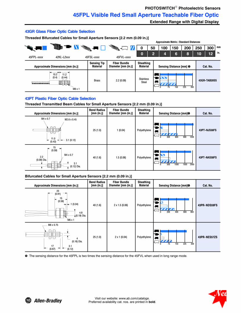
PHOTOSWITCHR Photoelectric Sensors
45FPL Visible Red Small Aperture Teachable Fiber OpticExtended Range with Digital Display
3Visit our website: www.ab.com/catalogs.Preferred availability cat. nos. are printed in bold.
43GR Glass Fiber Optic Cable Selection
Threaded Bifurcated Cables for Small Aperture Sensors [2.2 mm (0.09 in.)]
45FPL--xxxx 42KL--L2xxx
0 50 150100 200 250
Approximate Metric / Standard Distances
300120 2 64 8 10
45FSL--xxxx 45FVL--xxxx
mm
in.
Approximate Dimensions [mm (in.)]Sensing TipMaterial
Fiber BundleDiameter [mm (in.)]
SheathingMaterial Sensing Distance [mm] Cat. No.
10.2(0.4)
11.2(0.44)
M6 x 1
Brass 2.2 (0.09) StainlessSteel
0 75 150 225 300
43GR--TAB20SS
43PT Plastic Fiber Optic Cable SelectionThreaded Transmitted Beam Cables for Small Aperture Sensors [2.2 mm (0.09 in.)]
Approximate Dimensions [mm (in.)]Bend Radius[mm (in.)]
Fiber BundleDiameter [mm (in.)]
SheathingMaterial Sensing Distance [mm] Cat. No.
M2.6 x 0.45M4 x 0.7
3.1 (0.12)11.0(0.43)
25 (1.0) 1 (0.04) Polyethylene
0 300 600 900 1200
43PT--NJS56FS
M4 x 0.7
15(0.59)
2.2(0.09) Dia.
3.1(0.12) Dia.
40 (1.6) 1.5 (0.06) Polyethylene
0 500 1000 1500 2000
43PT--NAS58FS
Bifurcated Cables for Small Aperture Sensors [2.2 mm (0.09 in.)]
Approximate Dimensions [mm (in.)]Bend Radius[mm (in.)]
Fiber BundleDiameter [mm (in.)]
SheathingMaterial Sensing Distance [mm] Cat. No.
23(0.91)
4.8(0.19) Dia.
1 (0.04)
15(0.59)
M6 x 1
40 (1.6) 2 x 1.5 (0.06) Polyethylene
0 200 400 600 800
43PR-NDS59FS
3.1(0.12)
4(0.16) Dia.
M6 x 0.75
17(0.67)
25 (1.0) 2 x 1 (0.04) Polyethylene
0 75 150 225 300
43PR-NES57ZS
The sensing distance for the 45FPL is two times the sensing distance for the 45FVL when used in long range mode.
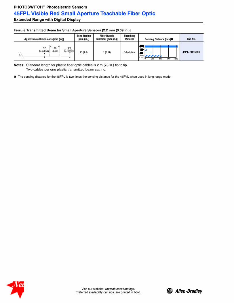
PHOTOSWITCHR Photoelectric Sensors
45FPL Visible Red Small Aperture Teachable Fiber OpticExtended Range with Digital Display
4 Visit our website: www.ab.com/catalogs.Preferred availability cat. nos. are printed in bold.
Ferrule Transmitted Beam for Small Aperture Sensors [2.2 mm (0.09 in.)]
Approximate Dimensions [mm (in.)]Bend Radius[mm (in.)]
Fiber BundleDiameter [mm (in.)]
SheathingMaterial Sensing Distance [mm] Cat. No.
15(0.59)
3.0(0.12) Dia.
2.2(0.09) Dia. 25 (1.0) 1 (0.04) Polyethylene
0 300 600 900 1200
43PT--CBS56FS
Notes: Standard length for plastic fiber optic cables is 2 m (78 in.) tip to tip.Two cables per one plastic transmitted beam cat. no.
The sensing distance for the 45FPL is two times the sensing distance for the 45FVL when used in long range mode.

PHOTOSWITCHR Photoelectric Sensors
ClearSighttClear Object Sensors
1--147Visit our website: www.ab.com/catalogs.Preferred availability cat. nos. are printed in bold.
ClearSight RightSight
ClearSight 9000
ClearSight 7000
FeaturesThree product families for applicationflexibility
S Configurable ClearSight 9000 forharsh duty glass and PET bottledetection
S ClearSight RightSight and 7000 forgeneral purpose plastic film andstretch-wrap detection
Specifications
9000 RightSight 7000
Environmental
Certifications cULus Listed and CE Marked for all applicable directives
Operating Environment NEMA 3, 4X, 6P, 12, 13, IP67 (IEC529); 1200 psi (8270 kpa)washdown for RightSight and Series 9000 models
Operating Temperature [C (F)] --34…+70°(--29…+158°)
--25…+55°(--13…+131°)
--40…+65°(+13…+150°)
Vibration 10…55 Hz, 1 mm amplitude, meets or exceeds IEC 60947--5--2
Shock 30 g with 1 ms pulse duration, meets or exceeds IEC 60947--5--2
Relative Humidity 35…85%
Ambient Light Immunity Incandescent light: 5000 lux
Optical
Sensing Modes Clear object
Sensing Range 1.2 m max 1 m max 1.5 m max
Field of View See Product Selection table on page 1--149
Light Source Visible red LED (660 nm)
Electrical
Voltage 10…40V DC;70…264V AC/DC 10.8…30V DC 11.8…28V DC
Current Consumption 30 mA max 35 mA max 46 mA max
Sensor Protection Short circuit, false pulse, reverse polarity, overload
Outputs
Response Time See Product Selection table on page 1--149
Output Type PNP and NPN, SDPT, SS relay, diagnostic output, see ProductSelection table on page 1--149
Output Mode Light or dark operate selectable, light or dark operate by cat. no. (seeProduct Selection table on page 1--149)
Output Current Refer to Product Selection table on page 1--149
Mechanical
Housing Material Valoxr Mindelr Valox
Lens Material Acrylic
Connection Types See Product Selection table on page 1--149
Supplied Accessories 92--90 Reflector
Optional Accessories See mounting brackets and cordsets on page 1--150
Wiring DiagramsFor Wiring Diagrams, please refer tobase product specifications:
ClearSight RightSight see page 1--32
ClearSight 9000 see page 1--66
ClearSight 7000 see page 1--103

PHOTOSWITCHR Photoelectric Sensors
ClearSighttClear Object Sensors
1--148 Visit our website: www.ab.com/catalogs.Preferred availability cat. nos. are printed in bold.
Approximate Dimensions [mm (in.)]
68.07(2.68)
97(3.8)
32.89(1.295)
42.41(1.670)
41.91(1.65)
Cable Length2 m (6.5 ft)6.47/6.22
(0.255/0.245)Dia.
39.50(1.555)
65.23(2.568)
15.87 (0.625)
47.88(1.885)
5.46 (0.215)
5.21 (0.205) x8.13 (0.320)Slot, 2 Plcs.
100.60 (3.961 )Max. Travel
24.64 (0.970)
30.35 (1.195)Centerline of Slots
120°
M30 x 1.5 ExternalThread 1/2 in. NPSM
Internal Thread
25.1(0.99)
13.41 (0.528)
20.96 (0.825)
Top View
Cable Version
ClearSight 9000
Dimensions for ClearSight RightSight and ClearSight 7000 are located on page 1--32 and 1--103, respectively.
Typical Response Curve Beam Pattern9000
Typical Response Curve Beam Pattern
OperatingMargin
Distance with 92- 90Reflector [mm (in.)]
10
1
Beam
Diameter—mm
RightSight
7000
0
1
2
OperatingMargin
10(0.4)
100(3.9)
1m(3.3ft)
10(33ft)
Distance to 92- 90Reflector [mm (in.)]
Distance [m (ft)]
Beam
Diameter—mm
--20
--10
0
10
20
0 1(3.3)
2(6.6)
3(9.8)
1
10
100
2540(100)
25.4(1.0)
254(10)
OperatingMargin
254(10)
2540(100)
25.4(1)
--0.2
0.2
0.40.6
0 304(12)
609(24)
914(36)
0.81
0
1219(48)
--0.4
--0.6--0.8--1
30
Distance to Reflector [mm (in.)]
Distance to 92- 90Reflector [mm (in.)]

PHOTOSWITCHR Photoelectric Sensors
ClearSighttClear Object Sensors
1--149Visit our website: www.ab.com/catalogs.Preferred availability cat. nos. are printed in bold.
Product Selection
Sensing ModeOperating VoltageSupply Current
SensingDistance
OutputEnergized
Output TypeCapacity
Response TimeConnection
Type Cat. No.
On/Off Sensors and Timing
Objectto beSensed
9000Field of View: 1.5_Emitter LED: Visible red 660 nm
10…40V DC30 mA
0.025…1.2 m(0.08…4 ft)
Light/DarkSelectable
NPN/PNP250 mA2 ms
2 m 300V cable 42G⊗C--9200
4-pin DC micro 42G⊗C--9200--QD
4-pin mini 42G⊗C--9200--QD1
70…264V AC/DC50/60 Hz15 mA
SPDT EM Relay2 A/132V AC/1 A/264V AC1 A/150V DC
15 ms
2 m 300V cable 42G⊗C--9202
5-pin mini 42G⊗C--9202--QD
45…264V DC/40…264V AC50/60 Hz15 mA
Solid State IsolatedN.O.300 mA2 ms
2 m 300V cable 42G⊗C--9203
4-pin mini 42G⊗C--9203--QD
4-pin AC micro 42G⊗C--9203--QD1
Objectto beSensed
RightSightField of View: 1.5_Emitter LED: Visible red 660 nm
21.6…264V AC/DC15 mA
25 mm…1 m(1 in…3.28 ft)
DarkOperate
N--MOSFET/100 mA8.3 ms
2 m 300V cable 42EF--C2SCA--A2
4-pin AC micro 42EF--C2SCA--G4
10.8…30V DC35 mA
NPN/PNP100 mA1 ms
2 m 300V cable 42EF--C2KBA--A2
4-pin DC micro 42EF--C2KBA--F4
Linear Polarized Sensors for Detection of Clear Films
Objectto beSensed
7000Field of View: 3_Emitter LED: Visible red 660 nm
11…28V DC46 mA
50 mm…1.5 m(2 in…4.9 ft)
Comple-mentaryL.O./D.O.
NPN100 mA1 ms
3 m cable 42SMU--7250
4-pin DC micro 42SMU--7250--QD
PNP100 mA1 ms
3 m cable 42SMU--7251
4-pin DC micro 42SMU--7251--QD
⊗ R for standard (i.e. 42GRC--9200)T for timing (i.e. 42GTC--9200)
Refer to page 1--150 for cordsets and accessories.

PHOTOSWITCHR Photoelectric Sensors
ClearSighttClear Object Sensors
1--150 Visit our website: www.ab.com/catalogs.Preferred availability cat. nos. are printed in bold.
Product Selection (continued)
Sensing ModeOperating VoltageSupply Current
SensingDistance
OutputEnergized
Output TypeCapacity
Response TimeConnection
Type Cat. No.
Circular Polarized Sensors for Detection of Clear Objects (Bottles, Clear Packages)
Objectto beSensed
7000Field of View: 3_Emitter LED: Visible red 660 nm
11…28V DC46 mA
50 mm…1.5 m(2 in…4.9 ft)
Comple-mentaryL.O./D.O.
NPN100 mA1 ms
3 m cable 42SMU--7260
4-pin DC micro 42SMU--7260--QD
PNP100 mA1 ms
3 m cable 42SMU--7261
4-pin DC micro 42SMU--7261--QD
Cordsets and AccessoriesDescription Cat. No. Description Cat. No.
2 m (6.5 ft), 4-pin DC Micro QD Cordset 889D--F4AC--2 Mounting Bracket Swivel/Tilt for ClearSight 7000 60--2619
2 m (6.5 ft) 5-pin DC Micro QD Cordset 889D--F5AC--2 Mounting Bracket Swivel/Tilt for ClearSightRightSight 60--2649
2 m (6.5 ft), 4-pin AC Micro QD Cordset, Straight 889R--F4AEA--2 Mounting Bracket Swivel/Tilt for ClearSight 9000and 10,000 60--2681
1.8 m (6 ft) 4-pin, Mini QD Cordset 889N--F4AF--6F Reflector 92--90 (included)
1.8 m (6 ft) 5-pin Mini QD Cordset 889N--F5AF--6F

PHOTOSWITCHR Photoelectric Sensors
45LPTOptical Label Sensor
1--151Visit our website: www.ab.com/catalogs.Preferred availability cat. nos. are printed in bold.
Description
The 45LPT is an optical label sensordesigned exclusively for the detectionof standard or opaque labels on ahigh speed web. The 45LPT providesa solution for packaging industryapplications such as label countingand web, “double sheet” and markdetection on a translucent film.
Features
S “One Touch” local and remoteteach capability
S 10…30V DC operation
S Fast 50 μsec response time
S User interface lockout feature
S IP65 housing
S Industrial anodized aluminumhousing
SpecificationsEnvironmental
Certifications cULus and CE Marked for all applicable directives
Operating Environment IP65
Operating Temperature [C (F)] --20…+60° (--4…+140°)
Vibration/Shock 10…55 Hz, 1.5 mm amplitude; meets or exceeds IEC 60947--5--2
Relative Humidity 5…95% (noncondensing)
Ambient Light Immunity Incandescent light 3000 lux
Optical
Sensing Mode Transmitted beam
Sensing Gap 3 mm (0.12 in.)
Light Source Nonpulsed infrared
Adjustments Push button for sensitivity adjustment, local and remote teach
Electrical
Voltage 10…30V DC
Current Consumption 40 mA max
Sensor Protection Short circuit, overload, transient noise, reverse polarity
Power ON Delay 350 ms
Outputs
Response Time 50 μs
Output Type PNP or NPN selectable
Output Mode Light or dark operate selectable
Output Current 100 mA max @ 30 V DC
Output Leakage Current 12V Supply: 0.78 mA @ 10 mA load, 6.9 mA @100 mA load24V Supply: 0.30 mA @ 10 mA load, 3 mA @ 100 mA load
Mechanical
Housing Material Aluminum
Connection Types 4-pin pico (M8) QD
Supplied Accessories None
Optional Accessories Cordsets
User InterfaceLabel Color State Condition
LEDsTeach Button
— Green
OFF Sensor power not present
Steady Sensor power present
Flash Fine teach—translucent label teach
— Red
OFF Output inactive
Steady Interface lockout
Flash Standard label teach
Red and green LED flash: SCP active or label too translucent or web to opaque.

PHOTOSWITCHR Photoelectric Sensors
45LPTOptical Label Sensor
1--152 Visit our website: www.ab.com/catalogs.Preferred availability cat. nos. are printed in bold.
Wiring Diagrams
3
2
1
4
3
2
1
4+
--
1
2
4
3
Brown
White
Black
Blue
Load
Pico
NPN (Light Operate)
NPN (Dark Operate)
PNP (Light Operate)
+
--1
2
4
3
Brown
White
Black
Blue
Load
+
--
PNP (Dark Operate)
+
--1
2
4
3
Brown
White
Black
Blue
Load
Pico+
--
1
2
4
3
Brown
White
Black
Blue
Load
+
--Remote teach = Connect white wire to (+) positive terminal.Remote teach = Connect white wire to (--) negative terminal.
Note: If remote teach (white wire) is not used, connect it to (--) negative terminal.Note: In the event of power failure, the sensor remembers the last threshold taught-in.
Approximate Dimensions [mm (in.)]
14 (0.55)
22.5(0.88)
80 (3.15)
12(0.47)
LEDsTeach Button
4.2 (0.16)Dia.
23 (0.9)
1 (0.03) 6(0.23)
3(0.11)
12(0.47)
37.5(1.47)
60 (2.36)15(0.59)
Optical Axis
5 (0.19)
6(0.23)
Product Selection
Operating VoltageSensing Gap[mm (in.)] Output Energized Output Type Response Time Connection Type Cat. No.
10…30V DC 3 (0.12) L.O./D.O.Selectable
NPN or PNPSelectable 50 μsec 4-pin Pico 45LPT- 1LEB1- P4
2 m (6.5 ft) pico QD Cordset 889P--F4AB--2
For Label detection use Darkoperate. For Web detection useLight operate.
IMPORTANT

PHOTOSWITCHR Photoelectric Sensors
45LFMCapacitive Label Sensor
1--153Visit our website: www.ab.com/catalogs.Preferred availability cat. nos. are printed in bold.
Description
The Allen-Bradley 45LFM capacitivelabel sensor uses an innovativeelectronic design to sense and/orcount labels. Its unique technologyenables it to sense the leading ortrailing edges of labels that are notdetectable by other similar sensors.The 45LFM provides an auto-teachfunction and a display to aid in initialsetup and operational efficiency.
Features
S Consistently senses the presenceof most labels on a web
-- Clear labels on clear backing
-- Clear labels on opaque backing
-- Metallic labels on clear backing
-- Opaque labels on clear backing
-- Metallic labels on opaquebacking
-- Opaque labels on opaquebacking
S Count 50,000 labels per minutewith registration error less than0.01 inch
S Heavy-duty metal housing
S Ideal for label counting and labelregistering applications
Specifications
Environmental
Certifications 45LFM--CMBA1--D5 meets CE Marked for all applicable directives
Operating Environment IP54
Operating Temperature [C (F)] 4…+50° (40…+120°)
Target Detection
Sensing Modes Capacitive
Registration Accuracy 0.025 mm (0.01 in.)
Minimum Sensing Gap 0.76 mm (0.03 in.)
LED Indicators Edge, zero
Adjustments Multi-turn potentiometer, selectable output polarity by wire
Electrical
Voltage 11…28V DC
Current Consumption 50 mA
Sensor Protection Short circuit, overload,reverse polarity
Power On delay 10 μs
Outputs
Response Time 10 μS
Output Type PNP and NPN
Output Mode Selectable output polarity by wire
Output Current 150 mA max
Output Leakage Current 5 μA max
Mechanical
Housing Material Anodized aluminum
Connection Types 5-pin DC micro (M12) QD
User Interface—45LFM--CMBA1--D5 User Interface—45LFM--CMBA2--D5Label Function Label Function
Gain Sensitivity Adjustment Shift Adjusts position of illuminated LED on display
Zero Gap Adjustment Span Sensitivity Adjustment

PHOTOSWITCHR Photoelectric Sensors
45LFMCapacitive Label Sensor
1--154 Visit our website: www.ab.com/catalogs.Preferred availability cat. nos. are printed in bold.
Approximate Dimensions [mm (in.)]
24.1(0.95)
24.1(0.95)
140 (5.5)
31.8(1.25)
GainAdjust
ZeroAdjust
Made in USAEdge Zero
Sensor
45LFM-CMBA1-D5 Ser A
140 (5.5)
31.8(1.25)
Made in USA
Label
Sensor
45LFM-CMBA2-D5 A Ser
Shift
WL
Span
Web
0.76 (0.03)
Wiring
Designation Lead Color (Cordset) 5-Pin Micro QD Pin Assignment
Termination 34
125
V+ Brown 1
--V Blue 2
PNP Output Black 3
NPN Output White 4
Output Polarity Grey 5
Product Selection
Operating Voltage Labels Sensed Output Type Response Time Connection Type Cat. No.
11…28V DC
OpaqueClear
NPN and PNP 10 μs 5-pin DC micro
45LFM--CMBA1--D5
OpaqueClearMetallic
45LFM--CMBA2--D5
2 m (6.5 ft) Micro QD Cordset 889D--F5AC--2
Note: Pin 5 must be connected to +V or ground for reliable detection.

PHOTOSWITCHR Photoelectric Sensors
45LSPOptical Fork Sensor
1--155Visit our website: www.ab.com/catalogs.Preferred availability cat. nos. are printed in bold.
Description
The 45LSP is family of optical forksensors housed in a plastic enclosure.Fork sensors offer self-containedtransmitted beam sensing, ideal forapplications that require reliable partsdetection. The simple push buttonteach-in sensitivity adjustment,several connection options andmultiple mounting features (via sidethru-holes, rear threaded inserts, oroptional dovetail brackets) make the45LSP an economical, easy to usesolution for typical applications suchas small parts detection, edgedetection, parts counting, gear toothdetection, dimension verifications, etc.
SpecificationsEnvironmental
Certifications cULus Listed and CE Marked for all applicable directives
Operating Environment IP67
Operating Temperature [C (F)] --20…+60° (--4…+140°)
Optical
Sensing Modes Transmitted beam
Sensing Gap 30, 50, 80, and 120 mm
Light Source Visible red LED (640 nm)
LED Indicators See User Interface below
Adjustments Teach button
Electrical
Voltage 10…30V DC
Current Consumption 30 mA max
Sensor Protection Short circuit, reverse polarity
Outputs
Response Time 250 μS
Output Type PNP or NPN by cat. no.
Output Mode Light or dark operate selectable (via teach button or remote)
Output Current 100 mA max
Mechanical
Housing Material Polycarbonate
Connection Types 4-pin DC pico (M8) QD connector, 3-pin DC pico (M8) QD connector
Optional Accessories Cordsets and dovetail mounting brackets
Features
S Detection of objects as small as0.2 mm (0.008 in.)
S Highly visible power and output LEDindicators with output indicationalong both sides of the fork
S Remote teach and teach button lockon 4-pin models
S Light or dark operate selectable
S Multiple mounting options:thru-holes, threaded holes anddovetail
S Easy installation with no alignmentrequired
S 3- and 4-pin pico (M8) QD models
User InterfaceLED Color State Status
Teach button Green LED
Orange LEDOrange LED
Orange
OFF Output de-energized
ON Output energized
Flashing Teach mode or short circuitprotection active
Green
OFF Power is OFF
ON Power is ON
Flashing Teach mode

PHOTOSWITCHR Photoelectric Sensors
45LSPOptical Fork Sensor
1--156 Visit our website: www.ab.com/catalogs.Preferred availability cat. nos. are printed in bold.
Wiring Diagrams
Brown (1) +
–
Black (4)White (2)
Blue (3)Load
Brown (1)
Black (4)White (2)
Blue (3)Load
Brown (1)+
–
Black (4)
Blue (3)Load
Brown (1)
Black (4)
Blue (3)Load
+
–
+
–314
3
42
1
3-Pin
NPN ModelsPNP Models
4-Pin 3-Pin 4-Pin
Remote teach.
Approximate Dimensions [mm (in.)] Cordsets and Accessories
C
Teach-inbutton
4
ED
AB
G F10
(0.39)
5(0.2)
4.5 (0.18)
12 (0.47)
4.5 (0.18)8 (0.31)
4.2 (0.17) 3x Dia.
Description Cat. No.
2 m (6.5 ft) 3-pin DC pico QD 889P--F3AB--2
2 m (6.5 ft) 4-pin DC pico QD 889P--F4AB--2
Dovetail mounting bracket 44B--BKT
M4 threaded inserts, 6 mm maximum depth.Dovetail mounting
Gap Size A B C D E F G
30 mm 30 (1.18) 50 (1.97) 30 (1.18) 34 (1.34) 59.5 (2.34) 20 (0.79) —
50 mm 50 (1.97) 70 (2.76) 50 (1.97) 54 (2.13) 79.5 (3.13) 20 (0.79) 28 (1.10)
80 mm 80 (3.15) 100 (3.93) 80 (3.15) 54 (2.13) 79.5 (3.13) 20 (0.79) 2 x 28
120 mm 120 (4.72) 140 (5.51) 120 (4.72) 54 (2.13) 79.5 (3.13) 20 (0.79) 3 x 28
Product Selection
Sensing GapResolution[mm (in.)] Operating Voltage Output Mode
ConnectionType Output Type Cat. No.
30 mm 0.2 (0.008)
10…30 V DCLight or darkoperateselectable
3-pin picoPNP 45LSP- 2LPA1- P3
NPN 45LSP--2LNA1--P3
4-pin picoPNP 45LSP--2LPA1--P4
NPN 45LSP--2LNA1--P4
50 mm 0.2 (0.008)
3-pin picoPNP 45LSP- 2LPA2- P3
NPN 45LSP--2LNA2--P3
4-pin picoPNP 45LSP--2LPA2--P4
NPN 45LSP--2LNA2--P4
80 mm 0.2 (0.008)
3-pin picoPNP 45LSP- 2LPA3- P3
NPN 45LSP--2LNA3--P3
4-pin picoPNP 45LSP--2LPA3--P4
NPN 45LSP--2LNA3--P4
120 mm 0.4 (0.016)
3-pin picoPNP 45LSP- 2LPA4- P3
NPN 45LSP--2LNA4--P3
4-pin picoPNP 45LSP--2LPA4--P4
NPN 45LSP--2LNA4--P4
Not over the entire temperature range. For maximum precision, allow for a heating period of approximately 15 minutes.For detection of objects less than 0.9 mm (0.035 in.), the object should be placed ≥10 mm away from the LED light source.

PHOTOSWITCHR Photoelectric Sensors
45LSTOptical Fork Sensor
1--157Visit our website: www.ab.com/catalogs.Preferred availability cat. nos. are printed in bold.
Description
The 45LST optical fork sensor isdesigned for small part detection onmachines and conveyors. Withavailable slot widths from 2…225 mm(0.08…8.86 in.), these sensors featureadjustable sensitivity and selectableNPN/PNP with L.O./D.O. energizedoutput in a heavy-duty IP65 aluminumhousing. Applications include labeldetection on clear substrates, capdetection on bottles, and part sensingon conveyors for the packaging andmaterial handling industries. The45LST sensors are also ideal for theautomotive, paper, and foodindustries.
Features
S 10…30V DC operation
S Fast 30 μsec response time forselected models
S NPN/PNP output
S IP65 housing
S Industrial aluminum housing
S cULus Listed and CE Marked for allapplicable directives
SpecificationsEnvironmental
Certifications cULus Listed and CE Marked for all applicable directives
Operating Environment IP65
Operating Temperature [C (F)] --20…+60° (--4…+10°)
Ambient Light Immunity Incandescent light 3000 lux
Optical
Sensing Modes Transmitted beam
Sensing Gap 2…225 mm (0.08…8.86 in.)
Light Source Nonmodulated infrared, infrared LED (880 nm)
LED Indicators See User Interface below
Adjustments 25 turn potentiometer
Electrical
Voltage 10…30V DC
Current Consumption 40 mA max
Sensor Protection Short circuit, reverse polarity, transient, overload
Power On Delay 129 ms
Outputs
Response Time 1 ms , 30 μS (45LST--1LEA1--P4 only)
Output Type PNP or NPN selectable
Output Mode Light or dark operate selectable
Output Current 100 mA max
Output Leakage Current 12V DC supply : 0.78 mA @ 10 mA load, 6.9 mA @ 100 mA load24V DC supply : 0.30 mA @ 10 mA load, 3.0 mA @ 100 mA load
Mechanical
Housing Material Anodized aluminum
Connection Types 4-pin DC pico (M8) QD connector
Optional Accessories Cordsets
User InterfaceLabel Color State Condition
Sensitivity Adjustment LEDs
— GreenOFF Sensor power not present
Steady Sensor power present
— RedOFF Output inactive
Steady Output active
Red and green LED flash: SCP active

PHOTOSWITCHR Photoelectric Sensors
45LSTOptical Fork Sensor
1--158 Visit our website: www.ab.com/catalogs.Preferred availability cat. nos. are printed in bold.
Wiring Diagrams
3
2
1
4
3
2
1
4+
--
1
2
4
3
Brown
White
Black
Blue
Load
Pico
NPN (Light Operate)
NPN (Dark Operate)
PNP (Light Operate)
+
--1
2
4
3
Brown
White
Black
Blue
Load
+
--
PNP (Dark Operate)
+
--1
2
4
3
Brown
White
Black
Blue
Load
Pico+
--
1
2
4
3
Brown
White
Black
Blue
Load
+
--White wire not used.
Approximate Dimensions [mm (in.)]
A20 (0.79)
LEDs
80 (3.15)
6(0.24)
6(0.24)
20 (0.79) + B
12 (0.47)M8 Plug
Sensitivity Adjustment
B16(0.63)
4 (0.16)R = 2.2
OpticalAxis
233(9.17)
20(0.79)
19.5(0 77)
68 (2.68)
B15(0.59)5 (0.20)
15(0.59)
A C
22.5(0.88)
12.25 (0.48)
22.75(0.89)
OpticalAxis
LEDs
12 (0.47)
Sensitivity Adjustment
4.2 (0.16) Dia.2 Places
225 mm 2…120 mm
D
Dimensions [mm (in.)]
Fork Size A B C D
2…120(0.08…4.72)
2 (0.08) 40 (1.57) 14 (0.55) 6.25 (0.25)
15 (0.59) 40 (1.57) 27 (1.06) 6.25 (0.25)
30 (1.18) 40 (1.57) 42 (1.65) 6.25 (0.25)
50 (1.97) 57 (2.24) 40 (1.57) 17.25 (0.68)
80 (3.15) 57 (2.24) 70 (2.75) 17.25 (0.68)
120 (4.72) 57 (2.24) 110 (4.33) 17.25 (0.68)
225 (8.86) 225 (8.86) 60 (2.36) — —

PHOTOSWITCHR Photoelectric Sensors
45LSTOptical Fork Sensor
1--159Visit our website: www.ab.com/catalogs.Preferred availability cat. nos. are printed in bold.
Product SelectionOperatingVoltage
Sensing Gap[mm (in.)]
OutputEnergized Output Type
Light SourceEmission
ResponseTime
ConnectionType Cat. No.
10…30V DC
2 (0.08)
LO/DOSelectable
NPN or PNPSelectable
Continuous 30 μsec
4-pin pico
45LST--1LEA1--P4
15 (0.59)
Modulated 1 ms
45LST--1LEA2--P4
30 (1.18) 45LST--1LEA3--P4
50 (1.96) 45LST--1LEA4--P4
80 (3.15) 45LST--1LEA5--P4
120 (4.72) 45LST--1LEA6--P4
225 (8.86) 45LST--1LEA7--P4
2 m (6.5 ft) pico QD Cordset 889P--F4AB--2

PHOTOSWITCHR Photoelectric Sensors
45MLAMeasuring Arrays and Controllers
1--160 Visit our website: www.ab.com/catalogs.Preferred availability cat. nos. are printed in bold.
DescriptionThe Allen-Bradley 45MLA is ameasurement sensor that utilizes anarray of transmitted beamphotoelectric sensor pairs to detectand measure objects. The arrayhousing is extremely compact,allowing for easy installation in arange of applications.
The 45MLA are packaged astransmitted beam pairs—the emitterand receiver arrays are both included.The system requires an Allen-Bradley45MLA controller, which must beordered separately. Three versions ofthe controller (I/O, RS485, CAN) areavailable, each offering a differentcommunications platform that can beselected to function with a range ofPLCs.
The controller drives the photoelectricelements in the emitter and reads outthe receiver beam information. Use ofthis external controller allows theflexibility to configure up to fourseparate sensing zones with indepen-dent outputs or the communication ofindividual beam status via serialprotocols. Additionally, the 45MLA canalso be customized for applicationspecific overhang and over-heightdetection.
FeaturesS Height measuring capabilityS Slim profile array housingS Long operating range—4 m (13 ft)S Fast reaction time and measure-
ment speedS Individual beam status available via
controller (serial communicationmodels only)
SpecificationsEnvironmental 45MLA Arrays 45MLA Controller
Certifications CE Marked for all applicable directives
Operating Environment IP54 Housing IP54, terminal stripIP20
Operating Temperature [C (F)] 0…55° (32…131°)
Storage Temperature [C (F)] --20…70° (--4…158°) --25…70° (--13…158°)
Vibration 10…55 Hz; amplitude 0.35 mm (0.01 in.); meets or exceedsIEC 60068--2--6
Shock Acceleration 10 g, pulse duration 16 ms, 10…55 Hz; amplitude0.35 mm (0.01 in.); meets or exceeds IEC 60068--2--29
Relative Humidity 15…95% 15…95%
OpticalSensing modes Transmitted beam pair —
Sensing Range 0…4 m (0…13 ft) —
Field of View 3.2° —
Light Source 940 nm —
Beam Spacing 10 mm (0.4 in.) or 25 mm (1.0 in.) —
Resolution 18 mm (0.7 in.) or 33 mm (1.3 in.) —
LED Indicators Red: StatusGreen: Alignment
Alignment, target present,outputs, inputs, power
ElectricalVoltage Provided by controller 20.4…27.6V DC ±5% max.
ripple
Current Consumption — <300 mA with max. no. ofbeams to controller, outputsnot connected
Sensor Protection EN61000--4--2, EN 61000--4--4 and EN 61000--4--5; short circuit(SCP), reverse polarity, and overload
OutputsResponse Time See 45MLA Controller User Manual
Output Type — NPN and PNP (push/pulloutput)
Output Mode — Dark operate (whenconnected as PNP)
Output Current — 150 mA max. each
MechanicalHousing Material Aluminum ABS(FR) UL94--V0
Lens Material Polycarbonate —
Cover Material Aluminum Polycarbonate
Connection Types 8-pin DC micro (M12) female QDon 500 mm (20 in.) cablepigtail—controller connection only
Spring loaded terminalconnections
Supplied Accessories Adjustable mounting kit (445L--AF6143)
Required Accessories Controller45MLA controller I/O model Cat. No. 45MLA--CTRL45MLA controller RS45 Cat. No.: 45MLA--CTRL--48545MLA controller CAN Cat. No. 45MLA--CTRL--CANLight array to controller connecting cable3 m (9.8 ft) M12—RJ45 Cat. No. 445L--AC8RJ35 m (16.4 ft) M12—RJ45 Cat. No. 445L--AC8RJ58 m (26.2 ft) M12—RJ45 Cat. No. 445L--AC8RJ8Max. system length cannot exceed 10 m (32.8 ft)
Optional Accessories Flat mounting kit Cat. No. 445L--AF6145

PHOTOSWITCHR Photoelectric Sensors
45MLAMeasuring Arrays and Controllers
1--161Visit our website: www.ab.com/catalogs.Preferred availability cat. nos. are printed in bold.
User InterfaceThe following table indicates LED status and descriptions for LEDs on the emitter and receiver light arrays.
Location LED Description Status Meaning
Emitter andReceiver Arrays
Green Light arrayalignment
Off Arrays not aligned (or target present)
On Arrays aligned (and target not present)
Flashing Low margin/light intensity inadequate
Red Light array statusOff Target not present (and arrays aligned)
On Target present (or arrays not aligned)
The following table indicates the status and description for each LED on the controller’s main PCB.
LED Description Color Meaning
D1 Light Array OK
Off Target present or light arrays not aligned
Green Target not present and light arrays aligned
Green flashing Low margin/light intensity inadequate
D2 Light array status
Off Target not present
Red Target present
Red Flashing Height Measurement Error
D3 Out1Off Output 1 inactive
Green Output 1 active
D4 Out2Off Output 2 inactive
Green Output 2 active
D5 In1Off Input 1 inactive
Green Input 1 active
D6 In2Off Input 2 inactive
Green Input 2 active
D7 PowerOff Power off
Green Power on

PHOTOSWITCHR Photoelectric Sensors
45MLAMeasuring Arrays and Controllers
1--162 Visit our website: www.ab.com/catalogs.Preferred availability cat. nos. are printed in bold.
Wiring Diagrams
The 45MLA is a “Three Box System.” Every setup consists of an emitter array, a receiver array, and an external controller.
Receiver Array
Emitter Array
45MLA Controller
Each controller has the same base PCB and a pre-installed extension PCB with model-specific functionality and additionalconnections.
In 2
PNP
NPNPNP
NPND7 LED -- Power
Model SpecificExtension PCB
D3 LED Out 1D4 LED Out 2D6 LED In 2D5 LED In 1
RJ45 ConnectorEmitter
RJ45 ConnectorReceiver
D2 LEDD1 LED
Gaps
In 1
Out 1Out 2In 1In 2N.C.Earth.24 V DC0 V DC
Pot 2Pot 1
RemovableSpring--Loaded
ConnectorInputLogicJumpers
S1
J2
J14

PHOTOSWITCHR Photoelectric Sensors
45MLAMeasuring Arrays and Controllers
1--163Visit our website: www.ab.com/catalogs.Preferred availability cat. nos. are printed in bold.
Connector J2 on the base PCB has the following pinout for all controller models.
Pin Signal Description
1 0V DC Power
2 +24V DC Power
3 Ground Ground
4 Not connected Not connected
5…8 Model specific functions (see below)
Pins 5…8 on connector J2 (on the base PCB) have different functionality with each controller model. The following tablesshow the pin connections for each specific model.
I/O Model RS485 and CAN models
Pin Signal Description Remarks Pin Signal Description Remarks
5 In 2Trigger and hold DIP switch S1 (7) = 0 5 In 2 Trigger and hold Special function
Overhang back sensor DIP switch S1 (7) = 1 6 In 1 Not used Not used
6 In 1Not used DIP switch S1 (7) = 0 7 Out 2 Light interrupted 0V = interrupted
Overhang front sensor DIP switch S1 (7) = 1 8 Out 1 Overhang 0V = overhang
7 Out 2 Light arrayinterrupted
0 V DC = interrupted24 V DC = notinterrupted
8 Out 1 Overhang 0 V DC = overhang24 V DC = no overhang
Or over--height (special function)
The extension PCB has connections specific to the functionality of each individual model. Here are the pin connections foreach model. The connectors are labeled on the PCB.
I/O ModelConnector J14
RS485 ModelConnector J16
CAN ModelConnectors J12 and J13 (RJ45)
Pin Signal 0V DC +24V DC Pin 2 Wire 4 Wire Pin Signal
1 Out 3 Zone Z1interrupted
Zone Z1 notinterrupted
1 0V DC 0V DC 1 CAN H
2 Out 4 Zone Z2interrupted
Zone Z2 notinterrupted
2 — Rx+ 2 CAN L
3 Out 5 Zone Z3interrupted
Zone Z3 notinterrupted
3 Shielding Shielding 3 0V DC
4 Out 6 Zone Z4interrupted
Zone Z4 notinterrupted
4 — Rx-- 4 Not connected
5 B Tx+ 5 Not connected6 A Tx-- 6 Shield
7 0V DC8 CAN V+

PHOTOSWITCHR Photoelectric Sensors
45MLAMeasuring Arrays and Controllers
1--164 Visit our website: www.ab.com/catalogs.Preferred availability cat. nos. are printed in bold.
Approximate Dimensions [mm (in.)]Arrays
8--pin female M12 (micro) QD
Cable clip 6 mmwhite (emitter)blue (receiver)
18.5(0.73)
500 (19.7)
B
A
20(0.79)
16(0.63)
1.5(0.06)
Controller200 (7.9)
188 (7.4)
176 (6.9)
128(5.0)
120(4.7)
80(3.1)
4.5(0.18)4x
31(1.2) 2x
5.0(0.2) 4x
45(1.8)
160 (6.3)
130 (5.1)
Note: The controller can be mounted either on a DIN Rail using the mounting brackets on the back or with four screws through the holes on the tabs extendingfrom the corners of the housing.

PHOTOSWITCHR Photoelectric Sensors
45MLAMeasuring Arrays and Controllers
1--165Visit our website: www.ab.com/catalogs.Preferred availability cat. nos. are printed in bold.
Product SelectionArrays
No. of Beams
AHousing Height
[mm (in.)]
BSensing Height[mm (in.)]
Beam Spacing[mm (in.)]
Length x Width[mm (in.)] Cat. No.
30 320 (12.6) 300 (11.8) 10 (0.39) 20 x 16 (0.79 x 0.62) 45MLA--AT0300P10
60 630 (24.4) 600 (23.6) 10 (0.39) 20 x 16 (0.79 x 0.62) 45MLA--AT0600P10
90 920 (36.2) 900 (35.4) 10 (0.39) 20 x 16 (0.79 x 0.62) 45MLA--AT0900P10
120 1220 (48.0) 1200 (47.2) 10 (0.39) 20 x 16 (0.79 x 0.62) 45MLA--AT1200P10
36 920 (36.2) 900 (35.4) 25 (0.98) 20 x 16 (0.79 x 0.62) 45MLA--AT0900P25
48 1220 (48.0) 1200 (47.2) 25 (0.98) 20 x 16 (0.79 x 0.62) 45MLA--AT1200P25
Controllers Accessories
Description Cat. No. Description Cat. No.
I/O Model 45MLA--CTRL Flat mounting kit (four pieces/set) 445L--AF6145
RS485 45MLA--CTRL--485 180° adjustable mounting kit(four pieces/set, included with
arrays)445L--AF6143
CAN 45MLA--CTRL--CAN
Cable—Light array to controller
3 m M12—RJ45
5 m M12—RJ45
8 m M12—RJ45
445L--AC8RJ3
445L--AC8RJ5
445L--AC8RJ8

PHOTOSWITCHR Photoelectric Sensors
45DLADiscrete Light Arrays
1--166 Visit our website: www.ab.com/catalogs.Preferred availability cat. nos. are printed in bold.
Description
The Allen-Bradley 45DLA discretelight array is an ON/OFF sensor thatutilizes an array of transmitted beamphotoelectric sensor pairs to detectobjects over a much wider span thantraditional sensors. The 45DLA arepackaged as transmitted beam pairs(the emitter and receiver arrays areboth included). The controls areintegrated into the array housing andno separate controller is required. Theemitter and receiver are opticallysynchronized and therefore do notneed to be wired together.
Features
S Integrated light array controller
S IP54
S Simple, flexible mounting
S Optically synchronized (noelectrical connection betweenemitter and receiver required)
S Push/pull (PNP/NPN) outputs(connect to sinking or sourcinginputs)
S Wiring selectable range and outputstate (light/dark operate)
S 30 mm resolution
S Sensing height of 118…734 mm(4.6…28.9 in.)
SpecificationsEnvironmental
Certifications cULus and CE Marked for all applicable directives
Operating Environment IP54
Operating Temperature [C (F)] --20°…+55° (--4°…+131°)
Vibration 2 g, 10…200 Hz; 20 sweeps each axis; meets or exceedsEN 60068--2--6
Shock 15 g, 11 ms, 3 x each axis; 10 g, 16 ms, 100 x each axis; meets orexceeds EN 60068--2--27 and EN 60068--2--29
Relative Humidity 5....95% (noncondensing)
Ambient Light Immunity 75,000 Lux
Optical
Sensing Modes Transmitted beam pair
Sensing Range 200…1500 mm (7.9…59 in.) or 1.0…8.0 m (3.3…26.2 ft)
Field of View Emitter (long range selected): 15°@ 3.0 m (9.8 ft)Receiver (when emitter has long range selected): 35°@ 3.0 m(9.8 ft)
Light Source Infrared LED (880 nm)
LED Indicators Green (transmitter only) = power, orange (receiver only) = targetpresent
Adjustments Selectable range (by wiring input)
Resolution 30 mm (1.2 in.)
Beam Pitch 22 mm (0.87 in.)
Number of Beams 4…32 by Cat. No.
Sensing Height 118…734 mm (4.65…28.9 in.) by cat. no.
Electrical
Voltage 14…30V DC
Current Consumption 50 mA @ 24V DC without load connected
Sensor Protection Short circuit (SCP), reverse polarity
Outputs
Response Time 25…165 ms by cat. no.
Power-On Time 100 ms + response time
Output Type PNP/NPN (single push/pull output)
Output Mode Dark or light operate selectable (by wiring)
Output Current 120 mA max.
Mechanical
Housing Material Aluminum
Housing Height 266…882 mm (10.5…34.7 in.) by cat. no.
Lens Material Polycarbonate
Cable Material PVC
Connection Type 4-pin DC micro (M12) on 150 mm (6 in.) cable pigtail
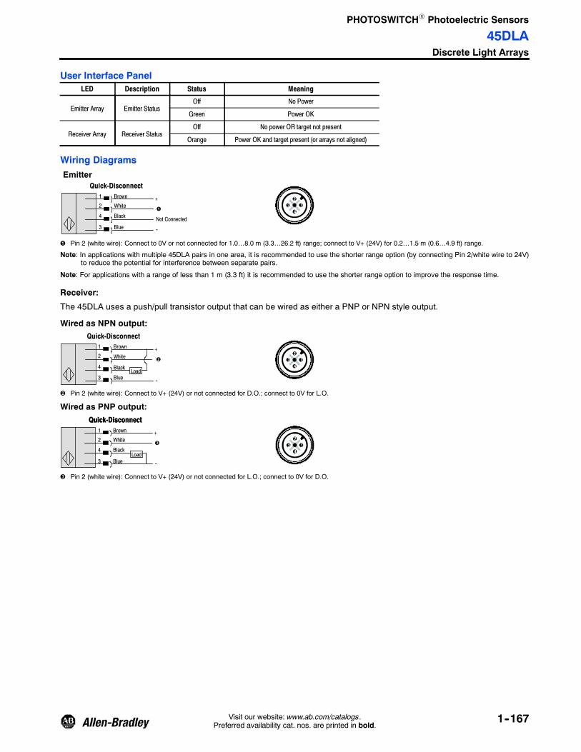
PHOTOSWITCHR Photoelectric Sensors
45DLADiscrete Light Arrays
1--167Visit our website: www.ab.com/catalogs.Preferred availability cat. nos. are printed in bold.
User Interface PanelLED Description Status Meaning
Emitter Array Emitter StatusOff No Power
Green Power OK
Receiver Array Receiver StatusOff No power OR target not present
Orange Power OK and target present (or arrays not aligned)
Wiring Diagrams
White
Emitter
+
--
1
2
4
3
Brown
Black
Blue
Quick-Disconnect
Not Connected
32
41
Pin 2 (white wire): Connect to 0V or not connected for 1.0…8.0 m (3.3…26.2 ft) range; connect to V+ (24V) for 0.2…1.5 m (0.6…4.9 ft) range.
Note: In applications with multiple 45DLA pairs in one area, it is recommended to use the shorter range option (by connecting Pin 2/white wire to 24V)to reduce the potential for interference between separate pairs.
Note: For applications with a range of less than 1 m (3.3 ft) it is recommended to use the shorter range option to improve the response time.
Receiver:
The 45DLA uses a push/pull transistor output that can be wired as either a PNP or NPN style output.
Wired as NPN output:
+
--
1
2
4
3
Brown
White
Black
Blue
Quick-Disconnect
Load
32
41
Pin 2 (white wire): Connect to V+ (24V) or not connected for D.O.; connect to 0V for L.O.
Wired as PNP output:
Black
White+
--
1
2
4
3
Brown
Blue
Quick-Disconnect
Load
Quick-Disconnect
32
41
Pin 2 (white wire): Connect to V+ (24V) or not connected for L.O.; connect to 0V for D.O.

PHOTOSWITCHR Photoelectric Sensors
45DLADiscrete Light Arrays
1--168 Visit our website: www.ab.com/catalogs.Preferred availability cat. nos. are printed in bold.
Approximate Dimensions [mm (in.)]150 (5.9)
A24(0.94)
12 (0.5)B
16(0.6)
C
D
7(0.28)
20 (0.79)
Note: Mounting from the front of the array (lens side) requires M4 flat head (countersunk) screws (included). Mounting from the side of the array requires M4pan head screws (not included).
No. of Beams
Approximate Dimensions [mm (in.)]
Cat. No.A: Housing Height B: Mounting Holes C: Sensing Height D: Pitch
4 266 (10.5) 92 (3.6) 118 (4.65) 22 (0.87) 45DLA--1LEB1T--F4
8 354 (13.9) 180 (7.1) 206 (8.11) 22 (0.87) 45DLA--1LEB2T--F4
16 530 (20.9) 356 (14.0) 382 (15.04) 22 (0.87) 45DLA--1LEB4T--F4
24 706 (27.8) 532 (20.9) 558 (21.97) 22 (0.87) 45DLA--1LEB6T--F4
32 882 (34.7) 708 (27.9) 734 (28.9) 22 (0.87) 45DLA--1LEB8T--F4
Product Selection
Sensing Height [mm (in.)] Response Time Cat. No.
118 (4.65) 25 ms 45DLA--1LEB1T--F4
206 (8.11) 45 ms 45DLA--1LEB2T--F4
382 (15.04) 85 ms 45DLA--1LEB4T--F4
558 (21.97) 125 ms 45DLA--1LEB6T--F4
734 (28.9) 165 ms 45DLA--1LEB8T--F4
Note: Both emitter (light source) and receiver arrays are included in the package. To identify the emitter, replace the “T” in the cat. no. with “E.” Toidentify the receiver, replace the “T” in the cat. no. with “R.” Example: 45DLA--1LEB2T--F4 contains one 45DLA--1LEB2E--F4 emitter array andone 45DLA--1LEB2R--F4 receiver array. Emitter and receiver arrays are not sold separately.
Cordsets and Accessories
Cordset Accessories
Description Cat. No. Description Cat. No.DC Micro QD Cordset,4-pin, 2 m (6.5 ft) 889D--F4AC--2 DC Micro Splitter 879D--F4DM
DC Micro QD Patchcord,4-pin, 2 m (6.5 ft) 889D--F4ACDM--2

PHOTOSWITCHR Photoelectric Sensors
45AST Area Array
1--169Visit our website: www.ab.com/catalogs.Preferred availability cat. nos. are printed in bold.
Features
S Introduces Two-Dimensional ArrayScanning Technology
S PNP or NPN Output
S Minimum object resolution from11…17 mm (0.43…0.66 in.)
S Sensing ranges up to 2.5 m (8.2 ft)
S IP67 rated housing
S CE Marked for all applicabledirectives
S Easy bracket-free mounting
S Highly visible alignment LEDs
SpecificationsEnvironmentalCertifications cULus and CE Marked for all applicable directives
Operating Environment IP67
Operating Temperature [C (F)] --5…+55° (23…+131°)
Vibration 10…55 Hz, 1 mm amplitude, meets or exceeds IEC 60947--5--2
Shock 30 g with 1 ms pulse duration, meets or exceeds IEC 60947--5--2
Relative Humidity 35…85%
Ambient Light Immunity 500 lux max.
Optical
Sensing Modes Transmitted beam
Sensing Range See Product Selection table on page 1--170
Number of Optical Axis See Product Selection table on page 1--170
Light Source Infrared LED (860 nm)
LED Indicators Green LED for transmitted, green LED for alignment on receiver, andthree orange LEDs for output
ElectricalVoltage 12…24V DC ±10% ripple
Current Consumption See Product Selection table on page 1--170
Sensor Protection Reverse polarity, short circuit protection
OutputsResponse Time 4 ms or 8 ms max by cat. no.
Output Type PNP or NPN by cat. no.
Output Mode Light operate
Output Current 100 mA @ 24V DC
Output Leakage Current 10 μA max
MechanicalHousing Material Aluminum
Lens Material Acrylic
Connection Types 2 m cable, 4-pin DC micro (M12) pigtail
Supplied Accessories None
Optional Accessories Mounting brackets, reflectors, cordsets
Wiring Diagrams
+
--
Brown
Black
Blue
Load
Blue
Brown +
--
Cable
NPN OutputPNP Output
+
--
Brown
Black
BlueLoad
+--
+ --
CableCable
Emitter

PHOTOSWITCHR Photoelectric Sensors
45AST Area Array
1--170 Visit our website: www.ab.com/catalogs.Preferred availability cat. nos. are printed in bold.
Approximate Dimensions [mm (in.)]
9.0(0.35)
Cable Dia. 4 (0.16)PVC: 3 m (9.8 ft)7.2
(0.28)
14.5(0.57)
8.2(0.32)
6.5(0.25)
B (Detecting Width)C B 6.5(0.25)
34 (1.33)
E
A
Detecting Width
Dia. 116.8 (4.6) x 2
Center of InstallationHole Pitch Center of Axis
F
G (Installation Hole Pitch)
2--M4
Model
[mm (in.)]
A B C D E F G
45AST--1J B1--A2 100 (3.93) 50 (1.96) 22.5 (0.88) 14.5 (0.57) 47.5 (1.87) 4 (0.15) 87 (3.42)
45AST--1J B2--A2150 (5.9) 100 (3.93) 22 (0.86) 15 (0.59) 72 (2.83) 3.5 (0.13)
137 (5.39)
45AST--1J B3--A2 137 (5.39)
45AST--1J B4--A2 200 (7.87) 150 (5.9) 22 (0.86) 15 (0.59) 97 (3.81) 3.5 (0.13) 187 (7.36)
N = NPN and P = PNP.
Product Selection
Current Consumption(max.)
RangeNumber ofOptical Axis
ResponseTime (max)
ResolutionDiameter[mm (in.)]
SensingHeight[mm (in.)] Output Type Cat. No.Transmitter Receiver
70 mA 65 mA 0.5…2 m(1.6…6.5 ft) 5 4 ms 15 (0.59) 50 (1.96)
PNP 45AST--1JPB1--A2
NPN 45AST--1JNB1--A2
80 mA 110 mA 0.15…0.8 m(0.49…2.62 ft) 10 8 ms 11 (0.43) 100 (3.93)
PNP 45AST- 1JPB2- A2
NPN 45AST--1JNB2--A2
80 mA 110 mA 0.5…2.5 m(1.6…8.2 ft) 10 8 ms 13 (0.51) 100 (3.93)
PNP 45AST--1JPB3--A2
NPN 45AST--1JNB3--A2
80 mA 110 mA 0.15…0.8 m(0.49…2.62 ft) 10 8 ms 17 (0.66) 150 (5.9)
PNP 45AST- 1JPB4- A2
NPN 45AST--1JNB4--A2
NPN versions available with longer lead times.Micro QD (M12) connector on pigtail models available. Refer to www.ab.com/sensors for more information.

PHOTOSWITCHR Photoelectric Sensors
45PVA Verification ArraySlim Type Picking Sensor
1--171Visit our website: www.ab.com/catalogs.Preferred availability cat. nos. are printed in bold.
Description
The Allen-Bradley 45PVA is aphotoelectric Parts Verification Arraydesigned for bin picking applicationsand object detection in the partsassembly industry. When used as partof a suitably configured bin-pickingsystem, the 45PVA effectivelyprevents mispicks to enhanceefficiency and minimize down time. Itis also the ideal solution to addressthe “error proofing” initiatives prevalentin the automotive industry.
The 45PVA uses an array of LEDs tocreate a light screen that can bespanned across bins at an assemblystation. By mounting the sensors onparts bins and wiring them into acontroller programmed with thenecessary logic, a virtually error-freebin-picking process can be achieved.“Job lights” on the 45PVA will not onlyshow the assembler the bins requiredto complete the current process, butwill also indicate the correct pickingsequence. In the event the assemblerattempts to pick an incorrect part, aselectable warning light on the 45PVAwill illuminate to indicate the error;additional fault enunciation can beachieved via controller logic inconjunction with a tower light or
SpecificationsEnvironmental
Certifications cULus and CE Marked for all applicable directives
Operating Environment NEMA 12; IP62
Operating Temperature [C (F)] Transmitted beam: 0…+50° (32…+122°)Retroreflective/diffuse: --10…+50° (14…+122°)
Vibration 10…55 Hz, 1.5 mm amplitude, 2 hours, X, Y, and Z direction
Shock 500 m/s, 3 times X, Y, and Z direction
Ambient Light Immunity 10,000 lux max
Optical
Sensing Modes Transmitted beam or retroreflective/diffuse selectable
Sensing Range Transmitted beam or retroreflective: 2 m (6.5 ft),Diffuse: 400 mm (15.7 in.)
Field of View
Light Source Infrared LED (880 nm) or visible red (640 nm)
LED Indicators See Approximate Dimensions on page 1--173
Adjustments DIP switches
Electrical
Voltage 12…264V DC
Current Consumption 46 mA max
Sensor Protection Short circuit protection
Outputs
Response Time See Product Selection table on page 1--174
Output Type PNP or NPN output selectable
Output Mode Light or dark operate selectable
Output Current 50 mA @ 30V DC max
Output Leakage Current 10 μA max
Mechanical
Housing Material Aluminum
Lens Material Polycarbonate
End Plate Material Resin
Connection Types 4-pin DC micro (M12) QD on 2 m pigtail
Supplied Accessories Basic mounting brackets, reflective tape (retro/diffuse models)
Optional Accessories See mounting brackets, reflectors, and cordsets on page 1--174
In addition to increasing efficiency andquality control by preventing faults inthe bin-picking process, the 45PVA isinstrumental in personnel stressreduction and the simplification ofpersonnel training—especially inmulti-lingual facilities.
FeaturesS Robust metal enclosure with super
slim 13 mm profileS Large highly-visible job indicator
lightsS Optional red fault light indicator to
notify operator of incorrectcomponent selection
S Dip switch selectable lightingoperation for job lights
S NPN or PNP dip switch selectableoutput reduces inventory
S Two frequency dip switch selectablecrosstalk protection
S Different sizes are available fordifferent component racks.Transmitted beam models areavailable in four sizes (100 mm(4 in.), 225 mm (9 in.), 300 mm(12 in.), and 375 mm (15 in.)).Retroreflective/diffuse models areavailable in two sizes (100 mm (4 in.)and 225 mm (9 in.)).

PHOTOSWITCHR Photoelectric Sensors
45PVA Verification ArraySlim Type Picking Sensor
1--172 Visit our website: www.ab.com/catalogs.Preferred availability cat. nos. are printed in bold.
Input/Output Circuit and Wiring DiagramsThe NPN/PNP input of the job indicator and the NPN/PNP output are selected by mode switch.
NPN Output(selected)
Pin 1 (Brown): 12 to 24V DC
Transmitter
Pin 3 (Blue): 0V
Pin 2 (Pink or White):Job Indicator Input
PNP Output(selected)
Pin 1 (Brown): 12 to 24V DC
Transmitter Receiver
Pin 3 (Blue): 0V
Pin 2 (Pink or White):Job Indicator Input
1
4
2
Transmitted Beam Receiverand Retroreflective/Diffuse
1
4
2
Face View Male Receptacle(Sensor) DC Micro
Job
Job
Pin 1 (Brown): 12 to 24V DC
Pin 3 (Blue): 0V
Pin 2 (Pink or White):Job Indicator Input
Pin 4 (Black): Output (NPN)
14
2Job
3
Pin 1 (Brown): 12 to 24V DC
Pin 3 (Blue): 0V
Pin 2 (Pink or White):Job Indicator Input
Pin 4 (Black): Output (NPN)
1
4
2Job
43
1
2
(NPN Output
Transmitter (not required forRetroreflective/Diffuse models)
Transmitted Beam Receiverand Retroreflective/Diffuse
Brown: 12 to 24V DCBlue: 0V
White: Job Indicator Input
Black: Out
Face View Male Receptacle(Sensor) DC Micro
14
3
2 Selected)(PNP OutputSelected)
43
1
2

PHOTOSWITCHR Photoelectric Sensors
45PVA Verification ArraySlim Type Picking Sensor
1--173Visit our website: www.ab.com/catalogs.Preferred availability cat. nos. are printed in bold.
Approximate Dimensions [mm (in.)]Dimensions are not intended to be used for installation purposes.
P
18(0.7)
32(1.25)
L1
JobIndicator 4.5 (0.17) Dia.
M
57 (2.24) 51 (2.0)
L2
Switch Cover
Light Status Indicator,Green/Orange (Receiver)Power, Green (Retro/Diffuse)
Dark Indicator, Orange (Receiver)Power Indicator, Green (Transmitter)Output ON Indicator, Orange (Retro/Diffuse)
13(0.51)
4.0 (0.15)
45PVR--1LEB1--F4 Ser A
2 m (6.5 ft)
Approximate Dimensions [mm (in.)]
Cat. No.N M L1 L2 P
5 100 (3.9) 130 (5.1) 140 (5.5) 25 (1.0) 45PVA--1LEB1--F4
10 225 (8.9) 255 (10.0) 265 (10.4) 25 (1.0) 45PVA--1LEB2--F4
13 300 (11.8) 330 (13.0) 340 (13.4) 25 (1.0) 45PVA--1LEB3--F4
16 375 (14.8) 405 (16.0) 415 (16.3) 25 (1.0) 45PVA--1LEB4--F4
4 87 (3.4) 130 (5.1) 140 (5.5) 29 (1.1) 45PVA--2LEA1--F4
8 203 (8.0) 255 (10.0) 265 (10.4) 29 (1.1) 45PVA--2LEA2--F4
Minimum Detectable Object SizeRetroreflective Mode
Specified
Typical
Distance [m (ft)]
1(3.3 ft)
0 0.5(1.6 ft)
1.5(4.9 ft)
2(6.6 ft)
20
30
40
50
60
70
80
90
0
10
Minimum
ObjectSize[mm]

PHOTOSWITCHR Photoelectric Sensors
45PVA Verification ArraySlim Type Picking Sensor
1--174 Visit our website: www.ab.com/catalogs.Preferred availability cat. nos. are printed in bold.
Product Selection
Sensing Mode Light SourceNumber of OpticalAxis [mm (in.)]
Detection Width[mm (in.)]
CurrentConsumption Response Time Cat. No.
Transmitted BeamInfrared LED,Wave-length880 nm
5 100 (3.93) 130 mA
Standard:
Standard: Light on: 35ms/Dark on: 25 ms
Interference Protection:Light on: 45 ms/Dark on:
28 ms
45PVA--1LEB1--F4
10 225 (8.85) 140 mA
Standard: Light on: 68ms/Dark on: 42 ms
Interference Protection:Light on: 84 ms/Dark on:
52 ms
45PVA--1LEB2--F4
13 300 (11.8) 150 mA
Standard: Light on: 70ms/Dark on: 42 ms
Interference Protection:Light on: 88 ms/Dark on:
54 ms
45PVA--1LEB3--F4
16 375 (14.7) 155 mA
Standard: Light on: 94ms/Dark on: 58 ms
Interference Protection:Light on: 116 ms/Dark on:
72 ms
45PVA--1LEB4--F4
Retroreflective/Diffuse
Visible Red LED,640 nm
4 100 (3.93) 68 mA120 ms
45PVA--2LEA1--F4
8 225 (8.85) 78 mA 45PVA--2LEA2--F4
AccessoriesMounting Brackets
11(0.43)
6(0.23)
4.6(0.18) Dia.
4.6(0.18) Dia.
10(0.39)
10(0.39)
20(0.78)
40 (1.57)
16(0.63)
18(0.7)
2 (0.07)
23(0.91)
#60--2773 (2 brackets)(included)

PHOTOSWITCHR Photoelectric Sensors
45PVA Verification ArraySlim Type Picking Sensor
1--175Visit our website: www.ab.com/catalogs.Preferred availability cat. nos. are printed in bold.
Optional Mounting BracketsMounting brackets available as an option (not included with sensor).
Plastic Bracket#60--2779 (2 brackets)
26.9(1.06) Dia.
66(2.60)
4.4 (0.17)
20.1(0.79)
18.8 (0.74)
7.4 (0.29)
18.0(0.71)
7.6 (0.30)
17.0 (0.67)
34.0 (1.34)
Metal Bracket#60- 2772 (2 brackets) 51.8 (2.04)
2 x M5 x 0.8
16.0(0.63)
18.0(0.71)
7.4 (0.29)
18.0 (0.71)
9.2 (0.36)
7.0 (0.27)
68.3 (2.69)
28.0 (1.10)Dia.
2.5(0.10)
5.2 (0.20)Dia.
2 x 16.0(0.63)
28 (1.1)
4 x M4 x 0.7
32.0(1.26)
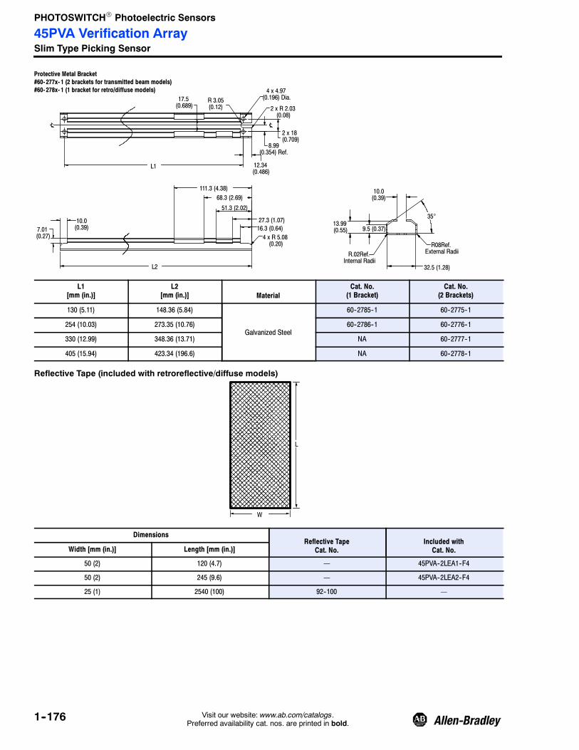
PHOTOSWITCHR Photoelectric Sensors
45PVA Verification ArraySlim Type Picking Sensor
1--176 Visit our website: www.ab.com/catalogs.Preferred availability cat. nos. are printed in bold.
Protective Metal Bracket#60- 277x- 1 (2 brackets for transmitted beam models)#60- 278x- 1 (1 bracket for retro/diffuse models)
L1
4 x R 5.08(0.20)
7.01(0.27)
16.3 (0.64)
17.5(0.689)
R 3.05(0.12)
12.34(0.486)
8.99(0.354) Ref.
2 x 18(0.709)
2 x R 2.03(0.08)
4 x 4.97(0.196) Dia.
10.0(0.39)
111.3 (4.38)68.3 (2.69)
51.3 (2.02)
27.3 (1.07)
L2
10.0(0.39)
9.5 (0.37)13.99(0.55)
35°
R08Ref.External RadiiR.02Ref.
Internal Radii32.5 (1.28)
L1[mm (in.)]
L2[mm (in.)] Material
Cat. No.(1 Bracket)
Cat. No.(2 Brackets)
130 (5.11) 148.36 (5.84)
Galvanized Steel
60--2785--1 60--2775--1
254 (10.03) 273.35 (10.76) 60--2786--1 60--2776--1
330 (12.99) 348.36 (13.71) NA 60--2777--1
405 (15.94) 423.34 (196.6) NA 60--2778--1
Reflective Tape (included with retroreflective/diffuse models)
L
W
DimensionsReflective Tape
Cat. No.Included withCat. No.Width [mm (in.)] Length [mm (in.)]
50 (2) 120 (4.7) — 45PVA--2LEA1--F4
50 (2) 245 (9.6) — 45PVA--2LEA2--F4
25 (1) 2540 (100) 92--100 —

PHOTOSWITCHR Photoelectric Sensors
44N Zone Control Sensor
1--177Visit our website: www.ab.com/catalogs.Preferred availability cat. nos. are printed in bold.
DescriptionThe 44N provides an economical,noncontact, solution to zero pressureaccumulation conveyor systems bycombining built-in zone control with aphotoelectric sensor. This simpleapproach replaces the conventionalmechanical switch sensing device,central PLC, and large quantities ofinterconnecting wiring.
The use of a photoelectric sensoreliminates the need for minimumweight restrictions required bymechanically actuated switches. Thepolarized retroreflective sensing modeensures reliable detection of evenshiny packages over a 4.8 m (16 ft)range.
The 44N comes complete with microQD connections to both an upstreamand downstream 44N along with avariety of connection options forcommon pneumatic valves. Power forthe 44N and the valve is distributedthrough these connections.
The zone logic of the 44N ensuresthat product being loaded on theconveyor will be separated into zonelength gaps thus providing zeropressure accumulation throughout theconveyor system. Once product hasaccumulated, it may be releasedindividually (singulate) orsimultaneously as a train (slug). Thisrelease is activated through anexternal contact closure.
Features
S Singulation release
S Slug release
S Adjustable 200 ms…10 secs ON(run) delay
S NEMA 4X rated
Specifications
Environmental
Certifications cULus Listed and CE Marked for all applicable directives
Operating Environment NEMA 4, 4X, 6, 12; IP67
Operating Temperature [C(F)] --20…+70° (--4…+158°)
Vibration 10…55 Hz, 1 mm amplitude, meets or exceeds IEC 60947--5--2
Shock 30 g with 1 ms pulse duration, meets or exceeds IEC 60947--5--2
Relative Humidity 5…95% (noncondensing)
Optical
Sensing Modes Polarized retroreflective
Sensing Range 50.8 mm…4.8 m (50.8 in…16 ft) with 92--39 reflector
Field of View 1.5°
Light Source Visible red (660 nm)
Adjustments On delay (200 ms…10 s), DIP switch
LED Indicators Green output LED indicator
Electrical
Voltage 10…30V DC
Current Consumption 20 mA max
Sensor Protection Overload, short circuit, reverse polarity, false pulse
Outputs
Response Time 2 ms
Output Type PNP
Output Mode Light or dark operate selectable by dip switch (1 L.O., 0 D.O.)
Output Current 100 mA @ 30V DC max
Mechanical
Housing Material Valoxr
Lens Material Acrylic
Connection Types 838 mm (33 in.) pigtail with 4-pin DC male micro QD (downstream)838 mm (33 in.) pigtail with 4-pin DC female micro QD (upstream)Cable connector for load (see Product Selection table)
Supplied Accessories 129--130 mounting nut
Optional Accessories See mounting brackets, reflectors, and cordsets on page 1--179

PHOTOSWITCHR Photoelectric Sensors
44N Zone Control Sensor
1--178 Visit our website: www.ab.com/catalogs.Preferred availability cat. nos. are printed in bold.
System Overview, Installation, and Operation
Install one 44N at the downstream sideof each zone and make both upstreamand downstream connections using themicro QD connectors. Connect theactuator lead of the 44N to the valvewithin its zone. Using an 889D--F4BC--2cordset, connect 24V DC to a suitablepower supply. A 4A supply will providepower for up to 25 zones when using a1W pneumatic valve. Connect the blacklead to the singulation release pushbutton and the white lead to the slugrelease push button. Both push buttonsshould be normally open andmaintained.
Loading Product Onto the ConveyorWith power applied to the system, allzones will immediately drive feedingproduct onto the conveyor. As productpasses the 44N mounted at the infeedzone, a gap will be formed equal to thezone length. This will ensure zeropressure throughout the system. Oncethe first product reaches the dischargezone (1), it will stop and await releasefrom the conveyor.
Release of Product from theConveyor:Once product has been transported andaccumulated at the discharge end ofthe conveyor (Zone 1), it may bereleased in one of two manners.
Singulation ReleaseWith the singulation release signalactive, only product in the dischargezone (1) will release. As the productclears the sensor, the adjacentupstream zones will advance into thedischarge zone. Product will continue todischarge as long as the zone releasepush button remains closed.
Slug ReleaseWith the slug release push buttonclosed and maintained, all accumulatedproduct on the conveyor will releasesimultaneously. When the slug releasepush button is released, the remainingproduct will resume normalaccumulation. This function overridesthe 44N logic and can be used to loadand unload product as a slug.
ZONE 1ZONE 4 ZONE 3 ZONE 2
valve
Slug Release
+24V DC
P4 P3 P2 P1
Direction of Product Flow
valvevalve valve
Figure 1. System Overview
Figure 2. Loading the Conveyor
Figure 3. Singulation Release of Accumulated Product
Figure 4. Slug Release of Accumulated Product
ZONE 4 ZONE 3 ZONE 2 ZONE 1
valveSingulation
Slug Release
+24V DC
P4 P3 P2 P1
Direction of Product Flow
valvevalve valve
ZONE 4 ZONE 3 ZONE 2 ZONE 1
valve Singulation
Slug Release
+24V DC
P4 P3 P2 P1
Direction of Product Flow
valvevalve valve
ZONE 1ZONE 4 ZONE 3 ZONE 2
Slug Release
+24V DC
P4 P3 P2 P1
Direction of Product Flow
valvevalvevalve valve
Release
Release
SingulationRelease
SingulationRelease
Refer to www.ab.com/sensors for more information.
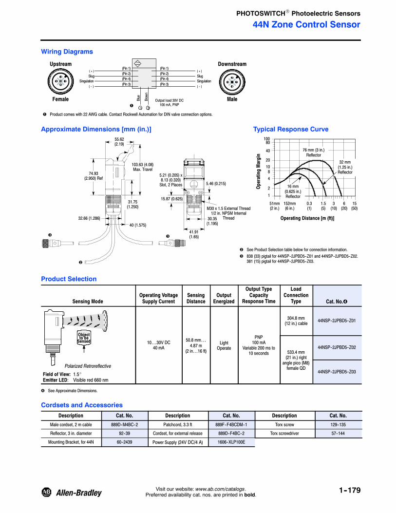
PHOTOSWITCHR Photoelectric Sensors
44N Zone Control Sensor
1--179Visit our website: www.ab.com/catalogs.Preferred availability cat. nos. are printed in bold.
Wiring Diagrams
Female
(Pin 1)
Blue
( + )
( -- )
Male
(Pin 2)(Pin 4)(Pin 3)
(Pin 1)(Pin 2)(Pin 4)(Pin 3)
SlugSingulation
( + )
( -- )
SlugSingulation
21
Brown
Upstream Downstream
Output load 30V DC100 mA, PNP
Product comes with 22 AWG cable. Contact Rockwell Automation for DIN valve connection options.
32
413
41
25
Approximate Dimensions [mm (in.)] Typical Response Curve
103.63 (4.08)Max. Travel
31.75(1.250)
40 (1.575)32.66 (1.286)
55.62(2.19)
74.93(2.950) Ref
M30 x 1.5 External Thread1/2 in. NPSM Internal
Thread
5.21 (0.205) x8.13 (0.320)Slot, 2 Places 5.46 (0.215)
15.87 (0.625)
41.91(1.65)
30.35(1.195)
OperatingMargin
Operating Distance [m (ft)]
1
2
481020
40
80100
16 mm(0.625 in.)Reflector
76 mm (3 in.)Reflector
32 mm(1.25 in.)Reflector
51mm(2 in.)
152mm(6 in.)
1.5(5)
0.3(1)
6(20)
3(10)
15(50)
See Product Selection table below for connection information.838 (33) pigtail for 44NSP--2JPBD5--Z01 and 44NSP--2JPBD5--Z02.381 (15) pigtail for 44NSP--2JPBD5--Z03.
Product Selection
Sensing ModeOperating VoltageSupply Current
SensingDistance
OutputEnergized
Output TypeCapacity
Response Time
LoadConnection
Type Cat. No.
Objectto beSensed
Polarized Retroreflective
Field of View: 1.5_Emitter LED: Visible red 660 nm
10…30V DC40 mA
50.8 mm…4.87 m
(2 in…16 ft)
LightOperate
PNP100 mA
Variable 200 ms to10 seconds
304.8 mm(12 in.) cable 44NSP--2JPBD5--Z01
533.4 mm(21 in.) right
angle pico (M8)female QD
44NSP--2JPBD5--Z02
44NSP--2JPBD5--Z03
See Approximate Dimensions.
Cordsets and Accessories
Description Cat. No. Description Cat. No. Description Cat. No.
Male cordset, 2 m cable 889D--M4BC--2 Patchcord, 3.3 ft 889F--F4BCDM--1 Torx screw 129--135
Reflector, 3 in. diameter 92--39 Cordset, for external release 889D--F4BC--2 Torx screwdriver 57--144
Mounting Bracket, for 44N 60--2439 Power Supply (24V DC/4 A) 1606--XLP100E

PHOTOSWITCHR Photoelectric Sensors
22ZC Zone Controller
1--180 Visit our website: www.ab.com/catalogs.Preferred availability cat. nos. are printed in bold.
DescriptionThe 22ZC Zone Controller bridges thegap between the 44N Zone ControlSensor and the 1799 embedded I/Omodule solutions. It offers thesimplicity of a smart sensor, yetprovides many of the advanced zonelogic functions found in a networked,programmable device.
By placing the zone logic in a singlezone controller, the user is given theflexibility to choose from a variety ofboth sensor input types (mechanical,optical) and actuator types(pneumatic, powered roller, DCmotor).
The 22ZC uses a proven, industrial,IDC displacement flat media schemefor a high power transfer to maximizethe number of zones connected to asingle power supply.
The 22ZC offers two basic, switchselectable operating modes. First, isthe single zone operation which is arun-on-demand system ideally suitedfor powered roller and DC motorapplications. The second is a basicmode which provides a constant drivefor both zero and low pressureaccumulation.
Other advanced logic functionsinclude selectable ON (RUN) andOFF (STOP) time delays, powerconservation, jam detection, alongwith air-to-drive and air-to-brakeoperation.
Specifications
Environmental
Certifications cULus Listed and CE Marked for all applicable directives
Operating Environment NEMA 1; IP50
Operating Temperature [C (F)] 0…+50° (32…+122°)
Vibration 10…55 Hz, 1 mm amplitude, meets or exceeds IEC 60947--5--2
Shock 30 g with 1 ms pulse duration, meets or exceeds IEC 60947--5--2
Relative Humidity 5…85% (noncondensing)
Zone Control
Zone Logic Switch selectable single or basic operating modes for zero and lowpressure accumulation with singulation and slug release
Advanced Zone Logic JAM respond function, sleep function, air-to-drive or air-to-brakeoperation, ON/OFF time delays
Adjustments Rotary switches, DIP switches
LED Indicators Orange (zone status, fault)
Electrical
Voltage 24V DC
Current Consumption 16 mA max
Sensor Protection Over-voltage, reverse polarity, short-circuit (SCP)
Outputs/Inputs
Response Time 1 ms
Sensor Input NPN
Actuator Output NPN
Output Mode Light or dark operate selectable by dip switch (1 L.O., 0 D.O.)
Actuator Output Current 100 mA @ 24V DC max
Mechanical
Housing Material Valoxr
Lens Material Acrylic
Connection Types Input: 3-pin MOLEX; Output: 4-pin MOLEX; Power/Signal: IDC Cable
Required Accessories Sensing device, actuating device, flat media
Optional Accessories Mounting brackets, reflectors, cordsets

PHOTOSWITCHR Photoelectric Sensors
22ZC Zone Controller
1--181Visit our website: www.ab.com/catalogs.Preferred availability cat. nos. are printed in bold.
System Overview for PneumaticallyDriven Conveyor Systems
Install one 22ZC in each zone of theconveyor and attach a suitable sensingand actuating device. Note that theinfeed module (22ZC--343) must beinstalled at the beginning of your zonecontrol system (zone 4 on Figure 1 onpage 1--182) and the master module(22ZC--413) at the discharge end ofyour system (zone 1 on Figure 1). Size,cut and install the flat media betweeneach controller. Connect a suitable 24VDC power supply to any controllerwithin the system. It is recommended tomake this connection to the centercontroller for balanced powerdistribution. A 4 A power supply willprovide power for up to 25 zones whenusing a 1 W pneumatic valve. Wire theinfeed and discharge zone externalconnection as required using the wiringdiagram shown on Figure 1.
Loading Product Onto the Conveyor(Figure 2 on page 1--182)
With power applied to the system, allzones will immediately drive feedingproduct onto the conveyor. As productpasses the sensor mounted at theinfeed zone, a gap will be formed equalto the zone length. This will ensure zeropressure throughout the whole system.Once the first product reaches thedischarge zone (zone 1), it will stop andawait release from the conveyor.
Release of Product
Once the product has been transportedand accumulated at the discharge endof the conveyor (zone 1) it may berelease in one of two manners:
Singulation Release (Figure 3 onpage 1--182)
With the singulation release signalactivate, only product in the dischargeend of the conveyor (zone 1) willrelease. As the product clears thesensors, the adjacent upstream zones
will advance into the discharge zone.Product will continue to discharge aslong as the singulation release signalremains active.
Slug Release (Figure 4 on page1--182)
With the slug release signal active, allaccumulated product on the conveyorwill release simultaneously. When theslug release signal is deactivated, theremaining product will resume normalaccumulation. Predetermined sluglengths can be configured through theuse of the slug respond switch on eachcontroller.
For more information on these andother features refer to the 22ZCinstallation instructions or visit ourwebsite at www.ab.com/sensors.
System Overview for Powered RollerDriven Conveyor Systems
Install one 22ZC in each zone of theconveyor and attach a suitable sensingand actuating device. Note that theinfeed module (22ZC--343) must beinstalled at the beginning of your zonecontrol system (zone 4 on Figure 1) andthe master module (22ZC--413) at thedischarge end of your system (zone 1on Figure 1). Size, cut and install the flatmedia between each controller.Connect a suitable 24V DC powersupply to any controller within thesystem. It is recommended to make thisconnection to the center controller forbalanced power distribution. Note thatthe power for the powered roller andamplifier are not provided by the 22ZC,only the RUN signal. Wire the infeedand discharge zone external connectionas required using the wiring diagramshown on Figure 1.
Loading Product onto the Conveyor(Figure 2 on page 1--182)
With power applied to the system, allzones will be OFF until either the infeed
sensor is blocked or the zone feed inputis closed and maintained. As productpasses the sensor mounted at theinfeed zone, a gap will be formed equalto the zone length. This will ensure zeropressure throughout the whole system.Once the first product reaches thedischarge zone (zone 1), it will stop andawait release from the conveyor. If alow pressure accumulation is desired, asystem wide OFF time delay can beconfigured to minimize product spacingon the conveyor.
Release of Product
Once the product has been transportedand accumulated at the discharge endof the conveyor (zone 1) it may berelease in one of two manners:
Singulation Release (Figure 3 onpage 1--182)
With the singulation release signalactivate, only product in the dischargeend of the conveyor (zone 1) willrelease. As the product clears thesensors, the adjacent upstream zoneswill advance into the discharge zone.Product will continue to discharge aslong as the singulation release signalremains active.
Slug Release (Figure 4 on page1--182)
With the slug release signal active, allaccumulated product on the conveyorwill release simultaneously. When theslug release signal is deactivated, theremaining product will resume normalaccumulation. Predetermined sluglengths can be configured through theuse of the slug respond switch on eachcontroller.
For more information on these andother features refer to the 22ZCinstallation instructions or visit ourwebsite at www.ab.com/sensors.

PHOTOSWITCHR Photoelectric Sensors
22ZC Zone Controller
1--182 Visit our website: www.ab.com/catalogs.Preferred availability cat. nos. are printed in bold.
Z4 Z3 Z2 Z1
Z4 Z3 Z2 Z1
Load
P4
Z4
P3
Z3
P2
Z2
P1
Z1
Load
ZONE 4 ZONE 3 ZONE 2 ZONE 1
+24V DC
Direction of Product Flow
Z4 Z3 Z2 Z1
ZONE 1ZONE 4 ZONE 3 ZONE 2
Direction of Product Flow
Figure 1. System Overview
Figure 2. Loading the Conveyor
Figure 3. Singulation Release of Accumulated Product
Figure 4. Slug Release of Accumulated Product
+24V DC
ZONE 1ZONE 4 ZONE 3 ZONE 2
Direction of Product Flow
Zone Feed
Zone State
Singulation
Slug ReleaseZone State
Zone Feed
Zone StateLoad Load
+24V DC
Zone Feed
Zone StateLoad Load
+24V DC
Zone Feed
Zone StateLoad Load
ZONE 4 ZONE 3 ZONE 2 ZONE 1
Direction of Product Flow
P4 P3 P2 P1
P4 P3 P2 P1
P4 P3 P2 P1
Release
Signal
Singulation
Slug ReleaseZone State
Release
Signal
Singulation
Slug ReleaseZone State
Release
Signal
Singulation
Slug ReleaseZone State
Release
Signal
Amplifier or Valve
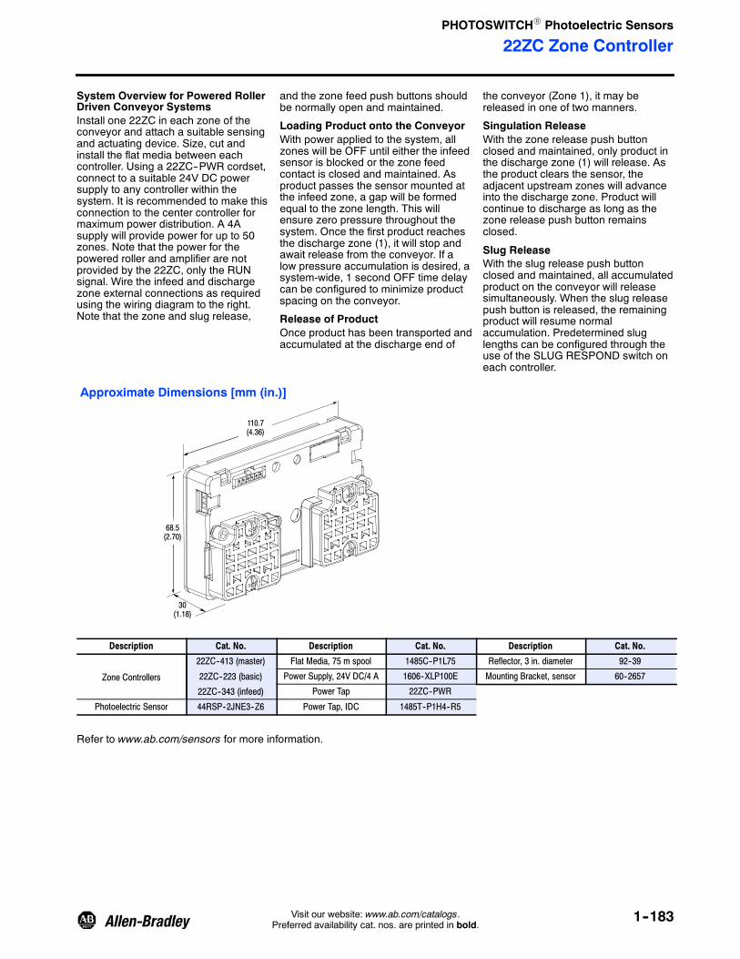
PHOTOSWITCHR Photoelectric Sensors
22ZC Zone Controller
1--183Visit our website: www.ab.com/catalogs.Preferred availability cat. nos. are printed in bold.
System Overview for Powered RollerDriven Conveyor SystemsInstall one 22ZC in each zone of theconveyor and attach a suitable sensingand actuating device. Size, cut andinstall the flat media between eachcontroller. Using a 22ZC--PWR cordset,connect to a suitable 24V DC powersupply to any controller within thesystem. It is recommended to make thisconnection to the center controller formaximum power distribution. A 4Asupply will provide power for up to 50zones. Note that the power for thepowered roller and amplifier are notprovided by the 22ZC, only the RUNsignal. Wire the infeed and dischargezone external connections as requiredusing the wiring diagram to the right.Note that the zone and slug release,
and the zone feed push buttons shouldbe normally open and maintained.
Loading Product onto the ConveyorWith power applied to the system, allzones will be OFF until either the infeedsensor is blocked or the zone feedcontact is closed and maintained. Asproduct passes the sensor mounted atthe infeed zone, a gap will be formedequal to the zone length. This willensure zero pressure throughout thesystem. Once the first product reachesthe discharge zone (1), it will stop andawait release from the conveyor. If alow pressure accumulation is desired, asystem-wide, 1 second OFF time delaycan be configured to minimize productspacing on the conveyor.
Release of ProductOnce product has been transported andaccumulated at the discharge end of
the conveyor (Zone 1), it may bereleased in one of two manners.
Singulation ReleaseWith the zone release push buttonclosed and maintained, only product inthe discharge zone (1) will release. Asthe product clears the sensor, theadjacent upstream zones will advanceinto the discharge zone. Product willcontinue to discharge as long as thezone release push button remainsclosed.
Slug ReleaseWith the slug release push buttonclosed and maintained, all accumulatedproduct on the conveyor will releasesimultaneously. When the slug releasepush button is released, the remainingproduct will resume normalaccumulation. Predetermined sluglengths can be configured through theuse of the SLUG RESPOND switch oneach controller.
68.5(2.70)
110.7(4.36)
30(1.18)
Approximate Dimensions [mm (in.)]
Description Cat. No. Description Cat. No. Description Cat. No.
Zone Controllers
22ZC--413 (master)
22ZC--223 (basic)
22ZC--343 (infeed)
Flat Media, 75 m spool 1485C--P1L75 Reflector, 3 in. diameter 92--39
Power Supply, 24V DC/4 A 1606--XLP100E Mounting Bracket, sensor 60--2657
Power Tap 22ZC--PWR
Photoelectric Sensor 44RSP--2JNE3--Z6 Power Tap, IDC 1485T--P1H4--R5
Refer to www.ab.com/sensors for more information.

PHOTOSWITCHR Photoelectric Sensors
Series 9000Intrinsically Safe
1--184 Visit our website: www.ab.com/catalogs.Preferred availability cat. nos. are printed in bold.
DescriptionThe Series 9000 transmitted beamphotoelectric sensors are designedand approved as an intrinsically safedevice under the FM and CSA entityconcept. It may be installed into aClass I, II, III; Division 1 hazardouslocation when connected to anappropriate safety barrier. The sensoris also approved as non-incendive forinstallation into Class I; Division 2hazardous locations without the needfor a safety barrier.
Typical applications
S AutomotiveS Petrochemical
S Grain processing
Information on the Series 897Hintrinsic safety barriers may be foundon page 12--2.
Features
S Intrinsically safe to North Americanstandards
S Transmitted beam sensing mode
S Compatible with Series 897Hintrinsic safety barriers
S 30 mm harsh duty package
S Fast response timeS Variety of connection types
Specifications
Environmental
Certifications UL Listed, FM Approved, and CE Marked for all applicable directives
Operating Environment NEMA 3, 4X, 6P, 12, 13; IP67, 1200 psi washdown, IP69K
Operating Temperature [C (F)] --40…+65° (--40…+150°)
Vibration 10…55 Hz, 1 mm amplitude, meets or exceeds IEC 60947--5--2
Shock 30 g with 1 ms pulse duration, meets or exceeds IEC 60947--5--2
Relative Humidity 5…95% max
Ambient Light Immunity Incandescent light 5000 lux
Optical
Sensing Modes Transmitted Beam
Light Source Infrared LED (880 nm)
LED Indicators Red LED for output indication
Adjustments Sensitivity potentiometer
Electrical
Voltage 13…30V DC
Current Consumption 25 mA max
Sensor Protection Overload, short circuit, reverse polarity, false pulse
Outputs
Response Time 10 ms max
Output Type PNP and NPN
Output Mode Light operate and dark operate selectable
Output Current 8.5 mA for PNP, 15 mA for NPN
Output Leakage Current 10 μA max
Mechanical
Housing Material ValoxR
Lens Material Acrylic
Connection Types 2 m cable, 4-pin DC micro (M12) QD, 4-pin DC mini QD
Supplied Accessories 129--130 mounting kit
Optional Accessories Series 897H intrinsic safety barriers, cordsets, mounting brackets
Selection Guide for Intrinsic Safety BarriersThe 42GRx--95x0 is approved as anintrinsically safe apparatus under theentity concept by FM and CSA.Therefore, any safety barrier whichmeets both the stated operational andsafety requirements (see Table 1) of the
sensor may be used. Note that thesensor is also approved asnon--incendive (FM) for installation intoClass I; Division 2 hazardous locationswithout the need for a safety barrier.
Table 1Entity Parameters
Sensor Barrier
Vmax 31.5V ≥ Vt
Imax 150 mA ≥ It
Pmax 0.95 W ≥ Pt
Ci + Cleads 0 uF ≤ Ca
Li + Lleads 0 mH ≤ La

PHOTOSWITCHR Photoelectric Sensors
Series 9000Intrinsically Safe
1--185Visit our website: www.ab.com/catalogs.Preferred availability cat. nos. are printed in bold.
User Interface
Label Color State Status
Output GreenOFF Sensor output de-activated
ON Sensor output activated
Margin/SCP Red
OFF Margin <2.5
ON Margin>2.5
Flashing Output SCP active
Power YellowOFF Sensor not powered
ON Sensor powered
Wiring Diagrams
143
12G
DIN Rail
Class I, II, III; Division 1 or 2;Group A, B, C, D, E, F, GHazardous Location
Nonhazardous Location
+--
Power Supply24…26V DC
34G
13 897H-S120
Intrinsic Safety Barrier
I.S. Ground Conductor
12G
+--
Power Supply24…26V DC
34G
897H-S214Intrinsic Safety Barrier
I.S. Ground Conductor
RLoad
DIN Rail
12G
+--
Power Supply24…26V DC
34G
12 897H-S150
Intrinsic Safety Barrier
I.S. Ground Conductor
3
DIN Rail
12G
34G
897H-S150Intrinsic Safety Barrier
Discrete InputModule
RLoad
42GRL Light Source
42GRR Receiver with PNP Output
42GRR Receiver with NPN Output
Discrete Input Module
T
T
T
IMPORTANT See Control Drawing #75002--200.

PHOTOSWITCHR Photoelectric Sensors
Series 9000Intrinsically Safe
1--186 Visit our website: www.ab.com/catalogs.Preferred availability cat. nos. are printed in bold.
41.91(1.650)
5.46(0.215)
27.05(1.065)
40.00(1.575)
32.66 (1.286)
69.85(2.750)
74.93(2.950) Ref
55.62(2.190)
16.76 (0.660)
31.75(1.250)
M30 X 1.5ExternalThread
1/2 in. NPSMInternal Thread 24.69
(0.970)
30.35(1.195)
15.87(0.625)
47.75(1.880)
42.41(1.670)
20.96(0.825)
7.62 (0.300)
15.24(0.600)
5.21 (0.205) X8.13 (0.320)Slot, 2 PLCS
Cable Version
Cable Length2 m (6.5 ft)
6.5 (0.255/0.245)Dia.
103.63(4.080)
Max. Travel
10
10000
1
4
40
100
400
1000
4000
0.3(1)
1.8(5)
3(10)
15(50)
30(100)
150(500)
Transmitted Beam
Operating Distance [m (ft)]
OperatingMargin
Typical Response CurveApproximate Dimensions [mm (in.)]
Product Selection
Sensing ModeOperating VoltageSupply Current Sensing Distance
OutputEnergized
Output TypeCapacity
Response TimeConnection
Type Cat. No.
Light Sources 14…30V DC16 mA
25.4 mm…106 m(2 in…350 ft)
— —
2 m 300V cable 42GRL--9540
4-pin micro 42GRL--9540--QD
4-pin mini 42GRL--9540--QD1
Receivers
Transmitted Beam
Field of View: 1.5_ ReceiverEmitter LED: Infrared 880 nm
Objectto beSensed13…30V DC
25 mA25.4 mm…106 m(2 in…350 ft)
Light/DarkOperate
NPN/15 mAPNP/8.5 mA10 ms max.
2 m 300V cable 42GRR--9500
4-pin micro 42GRR--9500--QD
4-pin mini 42GRR--9500--QD1
Cordsets and Accessories
Description Cat. No.
1.8 m (6 ft) 4-pin, Mini QD Cordset 889N--F4AF--6F
2 m (6.5 ft) 4-pin, DC Micro QDBlue Cordset 889D--F4LC--2
Mounting Bracket 60--2439
Intrinsically Safe wiring labels 897H--L1 or 897H--L2 must be applied every 7.6 m (25 ft).
Blue cable does not require labels to denote intrinsically safe wiring.

PHOTOSWITCHR Photoelectric Sensors
Series 5000Intrinsically Safe
1--187Visit our website: www.ab.com/catalogs.Preferred availability cat. nos. are printed in bold.
DescriptionThe Series 5000 intrinsically safesensors are designed for theinstallation in hazardous locations.They can be used in Class I, II, III;Division 1, 2; groups A, B, C, D, E, F,and G locations with intrinsic SafetyZener Diode Barriers. They can alsobe used in Class I, II, II; Division 2only without intrinsic safety zenerdiode barriers.
Features
S Intrinsically Safe to North Americanstandards
S Nonincendive for Division 2hazardous (classified) locations
S Modular package for increasedflexibility
S Wide variety of sensing modes
S Selectable light/dark operation
S Both NPN and PNP outputs
S Screw terminal connections
SpecificationsEnvironmentalCertifications UL Listed, FM Approved, and CE Marked for all applicable directives
Operating Environment NEMA 3, 4, 12, 13; IP66
Operating Temperature [C (F)] --40…+65° (--40…+150°)
Vibration 10…55 Hz, 1 mm amplitude, meets or exceeds IEC 60947--5--2
Shock 30 g with 1 ms pulse duration, meets or exceeds IEC 60947--5--2
Relative Humidity 90% max
Ambient Light Immunity Incandescent light 5000 lux
Optical
Sensing Modes Retroreflective, diffuse, polarized retroreflective, fiber optic
Sensing Range See Product Selection table on page 1--189
Field of View See Product Selection table on page 1--189
Light Source Infrared LED (880 nm)
LED Indicators Red LED for output indication
Adjustments Sensitivity potentiometer
Electrical
Voltage 24V DC with suitable intrinsically safe barrier
Current Consumption 30 mA max
Sensor Protection False pulse
Outputs
Response Time 1 ms
Output Type PNP and NPN
Output Mode Light and dark operate selectable
Output Current 20 mA @ 28V DC
Output Leakage Current 1 μA
Mechanical
Housing Material Valoxr
Lens Material Acrylic (glass on polarized lens)
Connection Types 2 m (6.5 ft) cable, screw terminal
Supplied Accessories None
Optional Accessories See mounting brackets, reflectors, and cordsets on page 1--190
User Interface
Label Color State Status
Output RedOFF Sensor output de-activated
ON Sensor output activated

PHOTOSWITCHR Photoelectric Sensors
Series 5000Intrinsically Safe
1--188 Visit our website: www.ab.com/catalogs.Preferred availability cat. nos. are printed in bold.
Wiring Diagrams
12G
+--
Power Supply24…26V DC
34G
897H-S120Intrinsic Safety Barrier
I.S. Ground Conductor
RLoad
DIN Rail
Discrete InputModule
Photohead and Terminal Base with PNP Output
+32-- 1
2G
34G
897H-S140Intrinsic Safety Barrier
Hazardous Location Nonhazardous Location
12G
+--
Power Supply24…26V DC
34G
+1
897H-S150Intrinsic Safety Barrier
I.S. Ground Conductor
--
DIN Rail
12G
34G
897H-S150Intrinsic Safety Barrier
RLoad
Photohead and Terminal Base with NPN Output—Groups C--G only
Discrete Input Module
IMPORTANT See Control Drawing #133--451.
Approximate Dimensions (Applies to all versions) [mm (in.)]
13.8(0.55)
2.7.(0.11)
38.3(1.50)
Top View
Bottom View
106.5(4.25)
71.0(2.80)
65.8(2.59)
55.5(2.19)
Terminal Style Power BaseTo Remove
55.5(2.19)
Photohead
Note: Hardware included with sensor: two (2) nickel-plated 10--32 mounting screws.
36.5(1.44)
36.5(1.44)
19.4(0.77)
8.7 Min.(1.03)
33.3(1.31) 8.3
(0.33)
15.4(0.45)
139.5(5.52)
27.7(1.09)
11.9(0.47)
24.2(0.95)
Quick-DisconnectScrew
LEDIndicator
1/2--14NPSM
10--32 UNF2 Holes

PHOTOSWITCHR Photoelectric Sensors
Series 5000Intrinsically Safe
1--189Visit our website: www.ab.com/catalogs.Preferred availability cat. nos. are printed in bold.
Typical Response CurveRetroreflective Polarized Retroreflective
1
20
100
Operating Distance [mm (in.)]
OperatingMargin
25.4(1.0)
4810
3m(10 ft)
OperatingMargin
20
40
3
6m(20 ft)
OperatingMargin
152(6.0)
Operating Distance [mm (in.)]
100
40
2010
21
Large Aperture Fiber Optic Wide Angle Lens
1
40
1000
OperatingMargin
25.4(1.0)
254(10)
OperatingMargin
40
200
10
4
2
609.6(24)
15m(50 ft)
Standard Diffuse
1
2
25.4(1.0)
2.54(0.1)
3m(10 ft)
152(6.0)
609.6(24)
15m(50 ft)
16 (0.625)Reflector
32 (1.25)Reflector
76 (3)Reflector
32 (1.25)Reflector
76 (3)Reflector
Fixed Focus Lens
4
25.4(1.0)
3m(10 ft)
152(6.0)
609.6(24)
15m(50 ft)
6.1m (20 ft)
400
200
20
4
ShortRange
Long Range
16(0.625)
32(1.25)
76 (3)Reflector
WhitePaper
25.4(1.0)
2.54(0.1)
3m(10 ft)
152(6.0)
609.6(24)
15m(50 ft)
1
1000
100
10
25.4(1.0)
12.7(0.5)
127(5.0)
1
1000
100
10
12.7(0.5)
508(20)
Operating Distance [mm (in.)]
OperatingMargin
Operating Distance [mm (in.)]Fibers #43GR--FAS25SL through #43GR--BAA72ML
See Fiber Optic section in this catalog for additional information.
Operating Distance [mm (in.)]Operating Distance [mm (in.)]
Product Selection
Photohead
Sensing Mode Sensing DistanceOutput
EnergizedOutput TypeCapacity Response Time Cat. No.
Objectto beSensed
Retroreflective
Field of View: 2.5_Emitter LED: Infrared 880 nm
50.8 mm…10 m(2 in…33 ft) with76 mm (3 in.)Reflector
Light/DarkSelectable
NPN and PNP20 mA at 29.5V
DC1 ms 42DRU--5500
Polarized Retroreflective
Field of View: 2.5_Emitter LED: Visible 660 nm
Objectto beSensed
50.8 mm…6 m(2 in…20 ft) with76 mm (3 in.)Reflector
Light/DarkSelectable
NPN and PNP20 mA at 29.5V
DC1 ms 42DRU--5700
Refer to page 1--190 for cordsets and accessories.

PHOTOSWITCHR Photoelectric Sensors
Series 5000Intrinsically Safe
1--190 Visit our website: www.ab.com/catalogs.Preferred availability cat. nos. are printed in bold.
Product Selection (continued)
Photohead
Sensing Mode Sensing DistanceOutput
EnergizedOutput TypeCapacity Response Time Cat. No.
Standard Diffuse
Field of View: 3_Emitter LED: Infrared 880 nm
Objectto beSensed 50.8 mm (2 in.)…Short
Range: 0.4 m (16 in.)Long Range: 2.1 m (7 ft)
with White Paper
Light/DarkSelectable
NPN and PNP20 mA at 29.5V
DC1 ms 42DRP--5500
Objectto beSensed
Large Aperture Fiber Optic
Field of View: Depends on the glass fiberoptics and lens type
Emitter LED: Infrared 880 nm
— Light/DarkSelectable
NPN & PNP20 mA at 29.5V
DC1 ms 42DRA--5500
Lens assembly required, see below.
Power Base
Style Operating Voltage Supply Current Cat. No.
Terminal 13…29.5V DC 26 mA max at 13V DC30 mA max at 29.5V DC 42DTB--5500
Lens Assembly
Lens Type Cat. No.
Fiber Optic 61--5550
Fixed Focus 61--5551
Wide Angle 61--5611
Cordsets and Accessories
Description Page No.
Mounting Assemblies 1--293
Intrinsic Safety Barriers 12--2
76 mm (3 in.) DiameterReflector 92--39
32 mm (1.25 in.) DiameterReflector 92--47

PHOTOSWITCHR Photoelectric Sensors
48MS MultiSighttVision Sensor
1--191Visit our website: www.ab.com/catalogs.Preferred availability cat. nos. are printed in bold.
Description
The MultiSight is an optical multi-pixelsensor with a pass/fail PNP output.The MultiSight uses several differentmethods of evaluation (patternmatching, contrast, brightness, andcontour matching) to detect ordifferentiate objects by means ofpreviously defined opticalcharacteristics, e.g. for separating“good” and “bad” parts. The mainapplications are in the field ofindustrial automation for qualityassurance purposes. The MultiSight isan easy-to-use economical alternativeto conventional vision systems fordetecting presence or absence,completeness, position, markings,labeling, packaging, and components.
FeaturesS Standalone vision sensorS Easy handling and setupS Compact, sturdy industrial housing
with IP67 ratingS Integrated lightingS Optional EtherNet/IPt connection
with RSLogixt 5000 Add-OnProfile for I/O data
S Adjustable focus from 20 mm toinfinity
S Short evaluation time (50…250 ms)S Multiple evaluation methods:
pattern matching, brightness,contrast, and contour matching
S Ten or 32 virtual detectorsS Individual virtual detectors can be
logically linked or grouped forevaluation of different objects withseveral characteristics forinspection
S Ethernet connection for setup
SpecificationsStandard Models EtherNet/IP Models
Certifications cULus Certified and CE Marked for all applicable directives
Lighting and Optics
Imager 640 x 480 pixels, CCD-monochrome; 256 level (8-bit) greyscale
Lighting Integrated LEDs; 6 x white, 2 x red
Lens Type 6 mm or 12 mm integrated lens, adjustable focus
Field of View 12 mm Lens: @ 200 mm; X = 60 mm, Y = 40 mm6 mm Lens: @ 200 mm; X = 150 mm Y = 100 mm(see Field of View table for details)
Sensing Range Min. range: 20 mm; max. range: infinite but dependent on illumination
Depth of Field ±5% of focusing distance
Electrical
Operating Voltage 24V DC ±10%
Current Consumption ≤200 mA
Open Circuit Protection Short circuit, overload, false pulse, transient noise, reverse polarity
Outputs OUT1 (pass/fail), OUT2 (position), OUT3 (illumination), OUT4 (ready)
Output Type 4 x PNP type (sourcing MOSFET)
Output Rating 200 mA per output; max. 9.6 W
Input Type IN1 (trigger) and IN2 (control); high 10…30V DC, low 0…3V DC
Ethernet Interface Configuration only Configuration (TCP/IP) and I/O(EtherNet/IP)
Mechanical
Housing Material Aluminum and ABS Plastic
Lens Material Plastic (PMMA)
LED Indicators Green: Power; Red: Error; Yellow (2): Q1, Q2 output
Connection Type Power--I/O: 8-pin micro QD (M12);Ethernet: 8-pin micro QD (M12)
Power--I/O: 8-pin micro QD (M12);Ethernet: 4-pin d-code micro QD(M12)
Enclosure Type Rating IP67
Vibration 10…55 Hz, 1.5 mm amplitude; 3 planes; meets or exceeds IEC60947--5--2
Shock 30 g; 11 ms; meets or exceeds IEC 60947--5--2
Operating Temperature [C (F)] 0…50° (32…122°)
Accessories
Supplied Accessory Dovetail bracket (48MS--BKTDT), focus adjustment screwdriver, 3mounting screws, Allen-wrench, software CD
Additional Required Accessory PWR and I/O cordset, ethernet cable
Optional Accessory Mounting brackets, cordsets, external lighting, trigger sensors
Detectors
Detector Types Pattern matching, brightness,contrast
Pattern matching, brightness,contrast, contour matching
Number of Detectors Up to 10 detectors Up to 32 detectors
Angular Displacement ±5° (for pattern matching); 360° (for contour matching)
Typical Cycle Time Pattern 50…100 ms; brightness 40…50 ms; contrast 40…50 ms;contour 120…500 ms
Number of Job Selects Combination of 10 detectors andjob selections
Combination of 32 detectors andjob selections

PHOTOSWITCHR Photoelectric Sensors
48MS MultiSighttVision Sensor
1--192 Visit our website: www.ab.com/catalogs.Preferred availability cat. nos. are printed in bold.
BenefitsS Perform multiple inspections with one
sensor
S Simple setup using PC andconfiguration software
S Multiple job storage to facilitateflexible product changeovers
S Simple inspection tools for detectingpresence or absence, completeness,position, markings, labeling,packaging, and components
S Economical alternative toconventional vision system
Product Selection
Focal Length of Lens Field of View EtherNet/IP Cat. No.
12 mm 12 mm @ 200 mm; X = 60 mm,Y = 40 mm No 48MS--SE1PF2--M2
6 mm 6 mm @ 200 mm; X = 150 mm,Y = 100 mm No 48MS--SE1PF1--M2
12 mm 12 mm @ 200 mm; X = 60 mm,Y = 40 mm Yes 48MS--SN1PF2--M2
6 mm 6 mm @ 200 mm; X = 150 mm,Y = 100 mm Yes 48MS--SN1PF1--M2
The 6 mm lens models typically require external lighting because the integrated lighting does not illuminate the entire field of view, i.e., the edges of the imageare dark.
Field of View
0
50
100
150
200
0 100(3.93)
200(7.87)
300(11.8)
400(15.7)
500(19.6)
600(23.6)
X
Y
FieldofView
[mm]
Operating Distance [mm (in.)]
0 100(3.93)
200(7.87)
300(11.8)
400(15.7)
500(19.6)
600(23.6)
X
Y
FieldofView
[mm]
Operating Distance [mm (in.)]
0
50
100
150
200
250
300
350
400
12 mm Lens 6 mm Lens

PHOTOSWITCHR Photoelectric Sensors
48MS MultiSighttVision Sensor
1--193Visit our website: www.ab.com/catalogs.Preferred availability cat. nos. are printed in bold.
Approximate Dimensions [mm (in.)]Dimensions are not intended to be used for installation purposes.
45 (1.77)
43(1.69)
11.6(0.46)
14(0.55)
13.1(0.51)
31.9(1.25)
2(0.79)
12.7(0.5)
64 (2.52)
M12 x 1
OpticalAxis
30.5(1.2)
30.5(1.2)
22.7(0.97)
22.5 (0.89)
Focus Adjustment
LED Indicators
M12 Connection Socket24 V DC and I/O
M12 Connection SocketENET
PWR--I/O ENET
5 6
7
8
4
3
1
2Rear View of the MultiSight
Connection: M12 (Micro) 8-pin MaleQD (PWR and I/O; Ethernet on
standard models)
Standard Models
Connection: 4-pin D Code Female QD(Ethernet connection forEtherNet/IP models)
3
21
4
45 (1.77)
43(1.69)
11.6(0.46)
2(0.79)
14(0.55)
13.1(0.51)
31.9(1.25)
16.5(1.77)
64 (2.52)
OpticalAxis 30.5
(1.2)
30.5(1.2)
22.7(0.97)
22.5 (0.89)
EtherNet/IP Models

PHOTOSWITCHR Photoelectric Sensors
48MS MultiSighttVision Sensor
1--194 Visit our website: www.ab.com/catalogs.Preferred availability cat. nos. are printed in bold.
Approximate Dimensions [mm (in.)] (continued)Dimensions are not intended to be used for installation purposes.
M4
1.8(0.07)
12.4(0.48)14.5(0.57)
605
20 (0.78)
10(0.39)
8(0.31)
15(0.59)
23(0.90)
10(0.39)
10(0.39)
Dovetail Bracket—48MS--BKTDT(included with MultiSight)
Angle Bracket—48MS--BKTANG
35(1.37)
35(1.37)
90°
3(0.11)
5(0.19)
9 (0.35)
R2.25(R.088)
10(0.39)
4.5(0.17)Dia.
14.25(0.56)
10(0.39)
20 (0.78)
R2.25(R.088)
10(0.39)
60°
4.5(0.17) Dia.
Rod Bracket—48MS--BKTROD
12.5(0.49)
10(0.39)
10 (0.39)
32(1.26)
20 (0.78) 10 (0.39)
M4 (10X)
Mounting Rod 200—48MS--ROD200
200 (7.87)
12 (0.47) Dia. M6
Mounting Rod 400—48MS--ROD400
12 (0.47) Dia.
400 (15.74)
Rod Clamp—48MS--CLAMP
MADE
ALLE
48MS--
A
A
11 (0.43)(4X)
20(0.78)
20(0.78)
6.8 (0.26)
6.3 (0.24) Dia.
10 (0.39)
Mounting Plate—48MS--MTPLATE
150 (5.90)100 (3.93)
50 (1.96)
30(1.18)
30(1.18)
90°
3(0.11)
5(0.19)
13 (0.51)
R2.25(R.088)
10(0.39)
4.5(0.17)Dia.
14.25(0.56)
10(0.39)
20 (0.78)
R2.25(R.088)
10(0.39)
60°
4.5(0.17) Dia.
Angle Bracket for Ring Light—48MS--BKTANG2
Rod Link—48MS--RODLINK
10 (0.39)
20(0.78)
16(0.63)
60 (2.36)
54 (2.13)
12 (0.47)Dia.
54 (2.13)
16(0.63)
10 (0.39)
20(0.78)
M4
60° 60°
32(1.26)
M6

PHOTOSWITCHR Photoelectric Sensors
48MS MultiSighttVision Sensor
1--195Visit our website: www.ab.com/catalogs.Preferred availability cat. nos. are printed in bold.
Approximate Dimensions [mm (in.)] (continued)Dimensions are not intended to be used for installation purposes.
IN
12.7(0.50)
30.5(1.20)
30.5
22.5(0.88)
22.65(0.89)
45 (1.77)
43(1.69)
31.4
11.6(0.45)
31.9 (1.25)
13.1(0.51)
14(0.55)
OUTPower
24(0.94)
Area Light (White Light)—48MS--ALWH
Ring Light (White Light)—48MS--RLWH
115 (4.52)Dia.
65 (2.55)Dia.
25(0.98)
12.7(0.50)
53.5(2.10)
10(0.39)
3X120°=360°
M4
Mounting Setup
Dovetail Bracket(48MS--BKTDT)
Angle Bracket(48MS--BKTANG)
Rod Bracket(48MS--BKTROD)
Mounting Plate(48MS--MTPLATE)
Mounting Rod(48MS--RODxxx)
Rod Clamp(48MS--RODLINK)
(1.20)M12 Male8-pin QDs
35°
30°
2 x M12 Male8-pin QDs

PHOTOSWITCHR Photoelectric Sensors
48MS MultiSighttVision Sensor
1--196 Visit our website: www.ab.com/catalogs.Preferred availability cat. nos. are printed in bold.
WiringPower I/O Connection
Pin (M12) Color Use
1 White IN1 (external trigger)
2 Brown 24V DC (V+)
3 Green OUT1 (pass/fail); display LED = Q1
4 Yellow OUT4 (ready)
5 Grey IN2 (control input)
6 Pink OUT3 (external illuminated trigger)
7 Blue GND (V+)
8 Red OUT2 (position); display LED = Q2
Indicates sensor evaluation is valid for OUT1 and OUT2, except in special cases as noted in the MultiSight User Manual.
Ethernet (Standard Models)
Pin (M12) Use
1 —
2 —
3 —
4 TxD--
5 RxD+
6 TxD+
7 RxD--
8 —
Ethernet (EtherNet/IP Models)
Pin (M12 D-Code) Use
1 Tx+
2 Rx+
3 Tx--
4 Rx--
Setup and Wiring
Power
Cordset(48MS--CS--2 ) Trigger
SensorOutput
TriggerSensor
48MS
Inspection Target
Enet Crossover Patchcord(48MS--ECSCROSS--3)
I/O
Power
TriggerSensorOutput
TriggerSensor
48MS
Inspection Target
Enet Cable(1585J--M8TBJM--2*)
I/O EnetSwitch
48MS--M12CVR
Enet Connector(1585A--DD4JD)
Standard Models EtherNet/IP Models
Enet Cordset(1585D--M4TBDM--2 )
8-Pin Micro Cordset(889D--F8AB--2 )
Other lengths available: replace 2 with length in meters (5 m and 10 m are standard lengths).

PHOTOSWITCHR Photoelectric Sensors
48MS MultiSighttVision Sensor
1--197Visit our website: www.ab.com/catalogs.Preferred availability cat. nos. are printed in bold.
Accessories
Product Descriptor Cat. No.
Dovetail Bracket 48MS--BKTDT
Angle Bracket 48MS--BKTANG
Rod Bracket 48MS--BKTROD
Mounting Rod 200 mm 48MS--ROD200
Mounting Rod 400 mm 48MS--ROD400
Rod Link 48MS--RODLINK
Rod Clamp 48MS--CLAMP
Mount Plate 48MS--MTPLATE
RJ45 Connector 48MS--RJ45CONN
Ethernet Crossover Cable, RJ45 to RJ45 48MS--ECROSS
Area Light—White Light 48MS--ALWH
Ring Light—White Light 48MS--RLWH
Angle Bracket for Ring Light 48MS--BKTANG2
Lighting Cable 48MS--LCS
Lighting Cable Right Angle 48MS--LCRT
MultiSight Test Box 48MS--TESTBOX
Standard ModelProduct Descriptor Cat. No.
Cordset 2 m 48MS--CS--2
Cordset 5 m 48MS--CS--5
Cordset 10 m 48MS--CS--10
Cordset Right Angle 2 m 48MS--CSRT--2
Cordset Right Angle 5 m 48MS--CSRT--5
ENET Cordset Crossover 3 m 48MS--ECSCROSS--3
ENET Cordset 3 m 48MS--ECS--3
Sealing Cap—M12 Male Connector 889A--DCAP
EtherNet/IP ModelProduct Descriptor Cat. No.
Power and I/O cordset—M12 8--pin female, 2 m 889D--F8AB--2
Cable Connector Cover (nonconducting)—M12 48MS--M12CVR
Sealing Cap—M12 Female Connector 1485A--M12
Ethernet Patchcord M12 D-code to RJ45—2 m 1585D--M4TBJM--2
Ethernet Patchcord M12 D-code to M12 D-code—2 m 1585D--M4TBDM--2
Ethernet M12 D-code to RJ45 converter 1585A--DD4JD
Ethernet Cable RJ45 to RJ45—2 m 1585J--M8PBJM--2
Ethernet Patchcord Crossover M12 D-code to RJ45—3 m 48MS--EPC--3
Included with MultiSight Sensor.Other lengths available: replace 2 with length in meters (5 m and 10 m are standard lengths).
Note: Additional accessories (longer cordsets and additional LED colors for external lighting) available with longer lead times. Consult your local RockwellAutomation sales office or Allen--Bradley distributor for additional information.

PHOTOSWITCHR Photoelectric Sensors
Series 9000Gate Entry
1--198 Visit our website: www.ab.com/catalogs.Preferred availability cat. nos. are printed in bold.
DescriptionThese UL 325 Recognized andUL 508 Listed photoelectric sensingsolutions are based on the industryproven Series 9000 and arespecifically designed for noncontactdetection of vehicles in automaticaccess control (gate entry)applications. These sensors areavailable individually or as bundledkits.
Features
S Complete sensing solutions basedon the industry proven Series 9000photoelectric sensors
S SPDT electro-mechanical relayoutput
S 24V AC/DC and 120/220V AC/DCmodels
S --34…+70°C (--29…+158°F)operating temperature range
S NEMA 3, 4X, 6P, 12, 14 (IP 67)environmental rating
S 1200 psi washdown ratingS Offered as kits or individual
components
SpecificationsEnvironmental
Operating Temperature [C (F)] --34…+70° (--29…+158°)
Relative Humidity 5…95% noncondensing
Operating Environment NEMA 2, 4, 4X, 6P, 13; IP67 (IEC 602529), 1200 psi (8270 kPa)washdown
Certifications UL 325 Recognized component for US and Canada and CE Marked forall applicable directives
Vibration 10…55 Hz, 1 mm amplitude, meets or exceeds IEC 60947--5--2
Shock 30 g with 1 ms pulse duration, meets or exceeds IEC 60947--5--2
Optical
Sensing Mode Retroreflective, transmitted beam
Sensing Distance 25.4 mm…9.15 m (1 in…30 ft) with AB #92--39 reflector,25.4 mm…6 m (1 in…20 ft) transmitted beam
Transmitting LED Visible red 660 nm, infrared (880 nm)
Field of View 1.5°
Operating Mode Light or dark operate selectable
Sensitivity Adjustment See User Interface on page 1--199
Electrical
Supply Current 40 mA
Power Consumption 2.2 W/1.6V A
Protection False pulse, reverse polarity, overload, short circuit
Output Type SPDT EM Relay
Output Load Current/Voltage 1 A @ 264V AC, 2 A @ 132V AC, 1 A @ 150V DC
Response Time 23 ms max.
Leakage Current Not applicable
Mechanical
Housing Material Valoxr
Lens Material Acrylic
Mounting Bracket #12 steel impact bracket
Connection Type 2 m 300V cable, 5-pin, AC mini QD

PHOTOSWITCHR Photoelectric Sensors
Series 9000Gate Entry
1--199Visit our website: www.ab.com/catalogs.Preferred availability cat. nos. are printed in bold.
User Interface
Label Color State Status
SensitivityAdjustment
Red Margin/SCP Indicator Green Output
Energized IndicatorYellow Power On
Indicator
Light/DarkOperate Switch
Top View Detail
Output GreenOFF Sensor output de-activated
ON Sensor output activated
Margin/SCP Red
OFF Margin < 2.5
ON Margin > 2.5
Flashing Output SCP active
Power YellowOFF Sensor not powered
ON Sensor powered
Wiring DiagramsCable Models 5--Pin AC/DC Mini QD Models
Brown
White (NC)
Black (NO)
Orange (C)
(+) L1
Blue (--) L2
4 Brown
5 White (NC)
1 Black (NO)
3 Orange (C)
(+) L1
2 Blue (--) L2
Approximate Dimensions [mm (in.)] Typical Response Curve
Mini Style
17.78 (0.700)
Mini Connector
10.3 m(1 ft)
51 mm(2 in)
80100
20
40
810
2
4
1.5 m(5 ft)
0.6 m(2 ft)
15 m(50 ft)
3 m(10 ft)
76 mm (3 in)Reflector
32 mm (1.25 in)Reflector
63.5(2.5)
75.0(2.9)

PHOTOSWITCHR Photoelectric Sensors
Series 9000Gate Entry
1--200 Visit our website: www.ab.com/catalogs.Preferred availability cat. nos. are printed in bold.
Product Selection—UL 325 Rated Retroreflective Sensor Kits
Description Contents Sensor Operating Voltage Cat. No.
24V UL 325 Kit
Sensor: 60--2728Mounting Bracket: 60--2421
Reflector: 92--39Impact Bracket: 60--2725
10…55V DC/20…40V AC 60--GR1--24UL325
120/220V UL 325 Kit
Sensor: 60--2730Mounting Bracket: 60--2421
Reflector: 92--39Impact Bracket: 60--2725
70…264V AC/DC 60--GR1--120UL325
Product Selection—UL 508 Rated Sensor Kits (General Purpose)
Description Contents of Kit Cat. No.
24V AC/DC Retroreflective Kit 42GRU--9001, 60--2421 Bracket, 92--39 Reflector 60--GR1--24
120/220V AC/DC Retroreflective Kit 42GRU--9002, 60--2421 Bracket, 92--39 Reflector 60--GR1--120
24V AC/DC Transmitted Beam Kit 42GRL--9000, 42GRR--9001, 60--2421 Bracket (2 pcs.) 60--GRR1--24
120/220V AC/DC Transmitted Beam Kit 42GRL--9000, 42GRR--9002, 60--2421 Bracket (2 pcs.) 60--GRR1--120
Refer to Series 9000 in the Sensors catalog for detailed specifications for sensor models included in above kits.
Replacement Sensors Product Selection
Description Details Cat. No.
24V UL 325 RetroreflectiveRetroreflective with 2 m Cable 60--2728
Retroreflective with 5-pin Mini QD 60--2729
120/220V UL 325 RetroreflectiveRetroreflective with 2 m Cable 60--2730
Retroreflective with 5-pin Mini QD 60--2731
Cordsets and Accessories
Description Cat. No.
Spare impact bracket for Series 9000 photoelectric sensor 60--2725
Spare mounting bracket for Series 9000 photoelectric sensor 60--2421
Spare reflector, 76 mm (3 in.) diameter with mounting hole 92--39
Spare reflector, 32 mm (1.25 in.) diameter with mounting hole 92--47
1.8 m (6 ft) 5-pin, mini QD cordset 889N--F5AF--6F

PHOTOSWITCHR Photoelectric Sensors
Series 9000Diagnostic
1--201Visit our website: www.ab.com/catalogs.Preferred availability cat. nos. are printed in bold.
DescriptionThe Series 9000 photoelectricsensors with diagnostic output aredesigned to provide both a visual andelectrical indication of a “dirty lens”condition. This is useful in applicationswhere dirt and dust build-up on theoptic lens are expected. This actionwill reduce the return light signal to thesensor thereby reducing its capabilityto reliably detect passing targets.
Features
S Both visual and electrical indicationof “dirty lens” condition
S Supports both static and diagnosticmodes of operation
S Harsh duty 30 mm package
S Wide selection of sensing modesS Both DC and AC/DC operationS Fast response time
S Variety of connection types
SpecificationsEnvironmentalCertifications UL Listed, CSA Approved, CE Marked for all applicable directives
Operating Environment NEMA 3, 4X, 6P, 12, 13; IP67 (IEC 529) 1200 psi (8270 kPa)washdown, IP69K
Operating Temperature [C (F)] 0…+70° (32…+158°)
Vibration 10…55 Hz, 1 mm amplitude, meets or exceeds IEC 60947--5--2
Shock 30 g with 1 ms pulse duration, meets or exceeds IEC 60947--5--2
Relative Humidity 5…95%
Ambient Light Immunity Incandescent light 5000 lux
Optical
Sensing Modes Retroreflective, polarized retroreflective, diffuse, transmitted beam
Sensing Range See Product Selection table on page 1--205
Field of View See Product Selection table on page 1--205
Light Source Visible red (660 nm), Infrared (880 nm)
LED Indicators See User Interface on page 1--202
Adjustments Single-turn potentiometer for sensitivity
Electrical
Voltage 10…30V DC, 95…264V AC/DC models
Current Consumption 30 mA max (DC models), 15 mA max (AC/DC models)
Sensor Protection Overload, short circuit, reverse polarity, false pulse
Outputs
Response Time 2 ms (DC models), 15 ms (AC/DC models)
Output Type PNP and NPN both sensor and diagnostic output (DC models)
SPST relay (sensor) with SPDT relay for diagnostic (AC/DC models)
Output Mode Light or dark operate selectable
Output Current 100 mA max @ 30V DC, 2 A @ 132V (AC/DC sensor and diagnostic),11 A @ 264V (AC/DC sensor and diagnostic)
Output Leakage Current 10 μA max
Mechanical
Housing Material ValoxR
Lens Material Acrylic
Cover Material Neoprene
Connection Types 4-pin DC micro QD, 4-pin DC mini QD, 5-pin DC micro QD
Supplied Accessories 129--130 mounting kit
Optional Accessories See mounting brackets, reflectors, and cordsets on page 1--206

PHOTOSWITCHR Photoelectric Sensors
Series 9000Diagnostic
1--202 Visit our website: www.ab.com/catalogs.Preferred availability cat. nos. are printed in bold.
User Interface
Label Color State
Diagnostic Operating Mode
Static Dynamic
POWERFLASHING
TGT SIGNAL LOWYellow
On Steady Sensor Power On
Flashing Unstable operation(0.7 < Margin < 1.5)
1.0 < Margin > 1.5 for seven successive operationsDiffuse: Target margin too low
Retro/Polarized Retro: Reflector margin too lowTransmitted Beam unbroken beam margin too low
FLASHING NON-TGTSIGNAL HIGH Green Flashing Unstable operation
(0.7 < Margin < 1.5)
0.7 < Margin > 1.0 for seven successive operationsDiffuse: Background margin too high
Retro / Polarized Retro: Target margin too highTransmitted Beam broken beam margin to high
STABILITYFLASHING SCP Red
On Steady Stable operation (Margin < 0.7 or Margin > 1.5)
Off Unstable operation (0.7 < Margin < 1.5)
Flashing Overload or short circuit at sensor output
OUTPUT Green On Output energized
To prevent potentially confusing indications during rapid signal transitions, the red STABILITY indicator has a typical delay of 100 ms before it turns off.As a result, the indicator will not turn off for quick, brief events. (The Diagnostic Output has no delay.)
10…30V DC sensors only.

PHOTOSWITCHR Photoelectric Sensors
Series 9000Diagnostic
1--203Visit our website: www.ab.com/catalogs.Preferred availability cat. nos. are printed in bold.
User Interface Panel—DC model shown
PNP
DIAG
NC
DK
STAT
NPN
NO
LT
DYN
SENSITIVITY
POWERFLASHINGTGT SIGNAL LOW
FLASHINGNON--TGTSIGNAL HIGH
STABILITYFLASHINGSCP
OUT
DYNAMIC Operating Mode
GREEN LEDOUTPUT
RED LEDSTABILITY INDICATOR
GREEN LEDNON--TARGET SIGNAL HIGH
YELLOW LED -- POWER ONTARGET SIGNAL LOW (FLASHING)
ON
OFF
INPUT SIGNALLEVEL
OR DIAGNOSTIC LOCATION (OFF)
FLASHING
ON OFF ON OFF ON
OFFON STEADY
FLASHING
1
2
3
INSTABILITYRANGE
1.5:1
0.7:1
7 INPUTS TRIPS DIAGNOSTICOUTPUT AND YELLOW LED
1:1
CONDITION 1 CONDITION 2
1
2
3
4
User Interface Panel—DC model shown (continued)
PNP
DIAG
NC
DK
STAT
NPN
NO
LT
DYN
SENSITIVITY
POWERFLASHINGTGT SIGNAL LOW
FLASHINGNON--TGTSIGNAL HIGH
STABILITYFLASHINGSCP
OUT
STATIC Operating Mode
HYSTERESIS
ON
OFF
INPUT SIGNALLEVEL
OUTPUT ON OUTPUT OFF
INSTABILITY RANGE
GREEN LEDOUTPUT
RED LEDSTABILITY INDICATOR
GREEN LEDNON--TARGET SIGNAL HIGH
YELLOW LED -- POWER ONTARGET SIGNAL LOW (FLASHING)
DIAGNOSTICOUTPUT
OFF ON OFF
ON OFF ON ONOFF
FLASHING
ON ON
OFF
FLASHING
ON
ONONOFF OFF OFF
OFF
TIME
MARGIN 1.5:1
MARGIN 0.7:1
1
2
3
4

PHOTOSWITCHR Photoelectric Sensors
Series 9000Diagnostic
1--204 Visit our website: www.ab.com/catalogs.Preferred availability cat. nos. are printed in bold.
Wiring Diagrams
43
1
2
Brown (1)
Black (4)
White (2)
Blue (3)
NPN
PNP
PNP
NPN
( + ) 10…30 V DC
( -- )
Sensor Output100 mA at 30V DC max.
Diagnostic Output100 mA at 30V DC max.
Micro Quick-DisconnectVersion (QD)
Mini Quick-DisconnectVersion (QD1)
AC Sensors
DC Sensors
Normally Open Mini Quick-DisconnectVersion (QD)
Sensor Output2 A at 120V AC1 A at 240V ACDiagnostic Output1 A at 120V AC0.5 A at 240V AC
( + ) L1
( -- ) L2Diagnostic output switch selectable
for either N.O. or N.C.
Sensor Output2 A at 120V AC1 A at 240V ACDiagnostic Output1 A at 120V AC0.5 A at 240V AC
( + ) L1
( -- ) L2Diagnostic output switch selectable
for either N.O. or N.C.
Normally Closed
Brown (4)Black (1)
Orange (3)
White (5)
Blue (2)
90…264V AC95…264V DC
90…264V AC95…264V DC
Brown (4)Black (1)
Orange (3)
White (5)
Blue (2)
DO NOT connect both an NPN andPNP load at the same time!
ATTENTION
Approximate Dimensions [mm (in.)]
41.91(1.650)
5.46(0.215)
27.05(1.065)
40.00(1.575)
32.66 (1.286)
69.85(2.750)
74.93(2.950) Ref
55.62(2.190)
16.76 (0.660)
31.75(1.250)
M30 X 1.5ExternalThread
1/2 in. NPSMInternal Thread 24.69
(0.970)
30.35(1.195)
15.87(0.625)
47.75(1.880)
42.41(1.670)
20.96(0.825)
7.62 (0.300)
15.24(0.600)
5.21 (0.205) X8.13 (0.320)Slot, 2 PLCS
Cable Version
Cable Length2 m (6.5 ft )
6.5 (0.255/0.245)Dia.
All Versions
103.63(4.080)
Max. Travel

PHOTOSWITCHR Photoelectric Sensors
Series 9000Diagnostic
1--205Visit our website: www.ab.com/catalogs.Preferred availability cat. nos. are printed in bold.
Typical Response CurveRetroreflective Polarized Retroreflective
1
20
100
Operating Distance [mm (in.)]
OperatingMargin
51(2.0)
4
10
3 m(10 ft)
OperatingMargin
20
40
6 m(20 ft)
OperatingMargin
152(6.0)
Operating Distance [mm (in.)]
40
20
10
2
1
40
10
4
2
609.6(24)
15 m(50 ft)
Standard Diffuse
1
2
51.0(2.0)
1.5 m(5 ft)
152(6.0)
0.3 m(1 ft)
15 m(50 ft)
16 (0.625)Reflector
32 (1.25)Reflector
32 (1.25)Reflector
76 (3)Reflector
4
3 m(10 ft)
152(6.0)
0.6 m(2 ft)
Operating Distance [mm (in.)]
1.5 m(5 ft)
16 (0.625)Reflector
3 m(10 ft)
6 m(20 ft)
51.0(2.0)
0.3 m(1 ft)
1.5 m(5 ft)
White Paper216 x 279.4(8.5 x 11)
1
1000
100
10
10000
OperatingMargin
15 m(50 ft)
3 m(10 ft)
0.3 m(1 ft)
150 m(500 ft)
30 m(100 ft)
1.8m(5 ft)
Transmitted Beam
76 (3)Reflector
Product Selection
Sensing ModeOperating VoltageSupply Current
SensingDistance
OutputEnergized
Output TypeResponse Time
ConnectionType Cat. No.
Objectto beSensed
Retroreflective
Field of View: 1.5_Emitter LED: Visible Red 660 nm
10…30V DC30 mA
50.8 mm…9.14 m(2 in…30 ft)with 76 mm(3 in.)Reflector
Light/DarkSelectable
NPN and PNP(Sensor and Diagnostic)100 mA @ 30V DC
2 ms
4-pin DC micro 42GDU--9000--QD
4-pin mini 42GDU--9000--QD1
90…264V AC95…264V DC
15 mA
SPST Relay N.O.(Sensor)15 ms
SPDT Relay, N.O. andN.C. (Diagnostic)
15 ms
5-pin mini 42GDU--9004--QD
SPST Relay N.C.(Sensor)15 ms
SPDT Relay, N.O. andN.C. (Diagnostic)
15 ms
5-pin mini 42GDU--9005--QD
Objectto beSensed
Polarized Retroreflective
Field of View: 1.5_Emitter LED: Visible Red 660 nm
10…30V DC30 mA
50.8 mm…4.87 m
(2 in…16 ft)with 76 mm
(3 ft)Reflector
Light/DarkSelectable
NPN and PNP(Sensor and Diagnostic)100 mA @ 30V DC
2 ms
4-pin DC micro 42GDU--9200--QD
4-pin mini 42GDU--9200--QD1
90…264V AC95…264V DC
15 mA
SPST Relay N.O.(Sensor)15 ms
SPDT Relay, N.O. andN.C. (Diagnostic)
15 ms
5-pin mini 42GDU--9204--QD
SPST Relay N.C.(Sensor)15 ms
SPDT Relay, N.O. andN.C. (Diagnostic)
15 ms
5-pin mini 42GDU--9205--QD
Refer to page 1--206 for cordsets and accessories.

PHOTOSWITCHR Photoelectric Sensors
Series 9000Diagnostic
1--206 Visit our website: www.ab.com/catalogs.Preferred availability cat. nos. are printed in bold.
Product Selection
Sensing ModeOperating VoltageSupply Current
SensingDistance
OutputEnergized
Output Type/Response Time
ConnectionType Cat. No.
Objectto beSensed
Standard Diffuse
Field of View: 3.5_Emitter LED: Infrared 880nm
10…30V DC30 mA
50.8 mm…1.52 m
(2 in…5 ft) toWhite Paper
Light/DarkSelectable
NPN and PNP(Sensor and Diagnostic)100 mA @ 30V DC/2 ms
4-pin DC micro 42GDP--9000--QD
90…264V AC95…264V DC
15 mA
SPST Relay N.O. (Sensor)15 ms
SPDT Relay, N.O. and N.C.(Diagnostic)/15 ms
5-pin mini 42GDP--9004--QD
SPST Relay N.C. (Sensor)15 ms
SPDT Relay, N.O. and N.C.(Diagnostic)/15 ms
5-pin mini 42GDP--9005--QD
For Light Sources
Objectto beSensed
Transmitted Beam
Field of View: 1.5_Emitter LED: Infrared 880 nm
10…264V AC/DC15 mA
25.4 mm…61 m
(1 in…200 ft)— —
4-pin DC micro 42GRL--9000--QD
4-pin mini 42GRL--9002--QD
10…264V AC/DC15 mA
25.4 mm…152 m
(1 in…500 ft)— —
4-pin DC micro 42GRL--9040--QD
4-pin mini 42GRL--9042--QD
For Receivers
Objectto beSensed
Transmitted Beam
Field of View: 1.5_Emitter LED: Infrared 880 nm
10…30V DC30 mA —
ReceiverLight/DarkSelectable
NPN and PNP(Sensor and Diagnostic)100 mA @ 30V DC/2 ms
4-pin DC micro 42GDR--9000--QD
4-pin mini 42GDR--9000--QD1
90…264V AC95…264V DC
15 mA— Light/Dark
Selectable
SPST Relay N.O. (Sensor)15 ms
SPDT Relay, N.O. and N.C.(Diagnostic)/15 ms
5-pin mini 42GDR--9004--QD
SPST Relay N.C. (Sensor)15 ms
SPDT Relay, N.O. and N.C.(Diagnostic)/15 ms
5-pin mini 42GDR--9005--QD
Cordsets and Accessories
Description Cat. No. Description Cat. No. Description Cat. No.
1.8 m (6 ft) 4-pin,Mini QD Cordset 889N--F4AF--6F 2 m (6.5 ft) 4-pin,
DC Micro QD Cordset 889D--F4AC--2 76 mm (3 in.) Diameter withCenter Mount Hole 92--39
1.8 m (6 ft) 5-pin,Mini QD Cordset 889N--F5AF--6F Mounting Bracket 60--2439 32 mm (1.25 in.) Diameter 92--47

PHOTOSWITCHR Photoelectric Sensors
Series 6000Compact
1--207Visit our website: www.ab.com/catalogs.Preferred availability cat. nos. are printed in bold.
Features
S Compact cylindrical package
S Wide selection of sensing modes
S Universal supply voltage models
S Both NPN or PNP outputs (DC)
S Fast response time
S Variety of connection types
SpecificationsEnvironmental
Certifications UL Listed, CSA Approved, and CE Marked for all applicable directives
Operating Environment NEMA 3, 4X, 6, 12, 13; IP67
Operating Temperature [C (F)] --40…+56° (--40…+150°)
Vibration 10…55 Hz, 1 mm amplitude, meets or exceeds IEC 60947--5--2
Shock 30 g with 1 ms pulse duration, meets or exceeds IEC 60947--5--2
Relative Humidity 5…95%
Ambient Light Immunity Incandescent light 5000 lux
Optical
Sensing Modes Retroreflective, polarized retro, diffuse, fixed focus, sharp cutoff, wideangle, transmitted beam
Sensing Range See Product Selection table on page 1--210
Field of View See Product Selection table on page 1--210
Light Source Visible red LED (660 nm), infrared LED (880 nm)
LED Indicators Red LED for output indication
Adjustments 4-turn sensitivity potentiometer
Electrical
Voltage 10…30V DC, 20…264V AC/DC
Current Consumption 35 mA max
Sensor Protection Reverse polarity, false pulse
Outputs
Response Time See Product Selection table on page 1--210
Output Type PNP and NPN (DC models); MOSFET (AC/DC models)
Output Mode Light or dark operate by cat. no.
Output Current See Product Selection table on page 1--210
Output Leakage Current 1 μA max
Mechanical
Housing Material Noryl
Lens Material Acrylic
Cover Material Neoprene
Connection Types 3 m (9.8 ft) cable, 4-pin DC micro (M12) QD, 4-pin AC micro (M12) QD
Supplied Accessories Mounting kit # 129--106--1 and 129--106--2
Optional Accessories See mounting brackets on page 1--212
User Interface Panel
Label Color State Status
Output RedOFF Sensor output de-activated
ON Sensor output activated

PHOTOSWITCHR Photoelectric Sensors
Series 6000Compact
1--208 Visit our website: www.ab.com/catalogs.Preferred availability cat. nos. are printed in bold.
Wiring DiagramsDC All Models Except TransmittedBeam Source and High Speed Diffuse
Transmitted Beam Source(42SRL--6000)
High Speed Diffuse(42SRP--6302)
32
41
Models: 42SR_- 6_ _2 and 6_ _3
Models: 42SR_- 6__2-QD and 6__3-QD
Cable Version
Quick-Disconnect Versions
CableRed
Orange
Gray
Blue
Black
( + )
Floating Current
Floating PNP Output
Current Sink (NPN)
( -- )
( -- ) Blue
White (NPN) Output
Load
Brown ( + )
Black (PNP) Output
Source (PNP)
Load10…30V DC
CableRed
Black
( + )
( -- )
Cable Version
Quick-Disconnect Version
10…30V DC
32
41
( -- ) Blue
White Not Used
Brown ( + )
Black Not Used
Red ( + )
Green (N.O.)
Cable Version—NPN Outputs
White (N.C.)
Load
Load
Black ( -- )
100ma
100 ma
Quick-Disconnect Version
10…30V DC
32
41
( -- ) Blue
White (NPN) N.C.
Brown ( + )
Black (PNP) N.O.
AC/DC All Models Except Transmitted Beam Source
Models: 42SR_- 6_ _4 and 6_ _5Cable
White
Orange
Black( -- )(L1)
Models: 42SR_- 6_ _6 and 6_ _7Cable
Brown
Black
Blue( -- )(L1)
Cable Versions Quick-Disconnect VersionsModels: 42SR_- 6_ _4-QD thru 6_ _7-QD
Red w/Black Trace (L1) -- Output Red
Red w/White Trace + (L2)
Green (GND) Not Used
Load Load
(+) 20…132V DC(L2) 20…132V AC
(+) 20…264V DC(L2) 20…264V AC
Transmitted Beam Source (42SRL--6006)
CableBrown
Blue
( + )
( -- )
Cable Version Quick-Disconnect Version
20…264V AC or DCRed w/Black Trace (L2)-- Red (Not Used)
Red w/White Trace + (L1)
Green (GND) Not Used
Note: Details regarding connection of Allen-Bradley Series 6000 photoelectric sensors to Allen-Bradley Programmable Controllers can befound in publication 42-2.0.All wire colors shown refer to Allen-Bradley quick-disconnect cables.

PHOTOSWITCHR Photoelectric Sensors
Series 6000Compact
1--209Visit our website: www.ab.com/catalogs.Preferred availability cat. nos. are printed in bold.
Approximate Dimensions [mm (in.)]DC Models
7.6(0.30)
6.4(0.25)
12.7(0.50)
11.8(0.46)
2.5(0.10)Max
3.6 (0.14) Dia.Clearing for #6--32HDW (2 holes)
14.61(0.57)
14.61(0.57)
3.6 (0.14) Dia.Clearing for #6--32HDW (2 holes)
20.4(0.80)
5(0.19)12.7
(0.50)
14(0.55)
6.4 (0.25)All Models Except Fiber Optic
66(2.60)
31.8(1.25)
1--20 UNEF2A Thread
25.4(1.0)
304(12.0)
Quick-disconnect cable length shown. Cable versions length is 3 m (10 ft).
Fiber Optic Models
73.7(2.90)
24.9(1.05)
RearView
25.4(1.0)
4 Turn Sensitivity PotRed Indicator LED4--Conductor Cable
19(0.75)
31.8(1.25)
1--20 UNEF2A Thread
M12 x 1
7.6(0.30)
6.4(0.25)
6.4(0.25)
2.5(0.10)Max
3.2 (0.125) Dia.
34.93(1.38)
34.93(1.38)304 (12.0)
6.4(0.25)
6.4(0.25)
6.4(0.25)
3.8(0.15)
M12 x 1
13.97 (0.55)
Micro StyleConnector Version
AC DC
Micro1/2--20 UNF2 Keyways
M12 x 11 Keyway
Thread Size
3.6 (0.14) Dia.Clearing for #6--32HDW (2 holes)
6.4(0.25)
6.4(0.25)
14.6(0.57)
3.6 (0.14) Dia.(2 holes)
2.5(0.10)Max
6.4(0.25)
5(0.19)
7.6(0.30)
12.7(0.50)
3.8(0.15)14
(0.55)
19(0.75)
All Models Except Fiber Optic
91.4(3.60)
57.2(2.25)
1--20 UNEF2A Thread
25.4(1.0)
304(12.0)
Quick-disconnect cable length shown. Cable versions length is 3 m (10 ft).
34.93(1.375)Fiber Optic Models
99.06(3.90)
24.9(1.05)
RearView
25.4(1.0)
4 Turn Sensitivity PotRed Indicator LED3 Conductor Cable
1/2--20 UNEF
1--20 UNEF2A Thread
57.2(2.25)
1/2--20 UNEF
6.4 (0.25)6.4(0.25)
20.4(0.80)
5.8 (0.230) Dia.
6.4(0.25)
2.5(0.10)Max
14.6(0.57)
304(12.0)
34.93(1.38)
12.7(0.50)
6.4(0.25)
7.6(0.30)
11.8(0.46)
Supplied Accessories
Mounting Kit #129--106--1 contains twoplastic nuts, anti-vibration mount, andslip pads.
Mounting Kit #129--106--2 contains twoplastic nuts, anti-vibration mount, slippads, and fiber optic mountinghardware.
Plastic Nuts
Series 6000 Sensor
Vibration Mount
Slip Pad
Slip Pad Plastic Nuts
34.9(1.37)Dia.
7.6(0.30)
3.8(0.15)
31.8(1.25)
1--20 UNEF2A Thread
Plastic Nuts

PHOTOSWITCHR Photoelectric Sensors
Series 6000Compact
1--210 Visit our website: www.ab.com/catalogs.Preferred availability cat. nos. are printed in bold.
Typical Response CurveRetroreflective Polarized Retroreflective
1
20
100
Operating Distance [mm (in.)]
OperatingMargin
25.4(1.0)
4
10
3 m(10ft)
OperatingMargin 20
40
6m(20ft)
OperatingMargin
152(6.0)
Operating Distance [mm (in.)]
10
76
2
1
40
10
4
2
15m(50ft)
Retroreflective Code Reader
1
2
1.5m(5ft)
152(6.0)
15m(50ft)
16 (0.625)Reflector
32 (1.25)Reflector
76 (3)Reflector
4
152(6.0)
0.6m(2ft)
Operating Distance [mm (in.)]
1.5m(5ft)
3 m(10ft)
6m(20ft)
254(10)
1
40
20
10
100
OperatingMargin
Standard Diffuse
40
25.4(1.0)
0.6m(2ft)
5
3
25.4(1.0)
76.2(3.0)
4
2
152(6.0)
3 m(10ft)
25.4(1.0)
0.6m(2ft)
2.54(0.1)
279 x 431(11 x 17)
White PaperResponse
Operating Distance [mm (in.)]
Fixed Focus Diffuse Sharp Cutoff Diffuse
1
20
100
Operating Distance [mm (in.)]
OperatingMargin
2.5(0.1)
4
10
76.2(3)
OperatingMargin
20
100
OperatingMargin
152(6.0)
Operating Distance [mm (in.)]
10,000
10
1
40
10
4
2
Wide Angle Diffuse
12
152(6.0)
WhitePaper
9.39(0.37)
Operating Distance [mm (in.)]
25.4(1.0)
279 x 431(11 x 17)
White Paper
1X
40X
20X
10X
100X
OperatingMargin
Transmitted Beam
40
25.4(1.0)
25.4(1.0)
76.2(3.0)
4X
2X
3020 4010
Operating Distance [mm (in.)]
2.54(0.1)
7.62(0.3)
76.2(3)
100
1000
4000
2.54(0.1)
7.62(0.3)
0.3 m(1ft)
0.6m(2ft)
80X
8X
279 x 431(11 x 17)
White Paper
WhiteThread
Transmitted BeamOperating Range Selection
Recommended operatingrange derating for “dirty”industrial environments.
Recommended operatingrange derating for “normal”industrial environments.
30.5m (100ft)
36.6m (120 ft)
1008050
16 (0.625)Reflector
32 (1.25)Reflector
76 (3)Reflector
Product Selection
Sensing ModeOperating VoltageSupply Current
SensingDistance @1X Margin
OutputEnergized
Output TypeResponse Time
ConnectionType Cat. No.
Objectto beSensed
Retroreflective
Field of View: 3_Emitter LED: Infrared 880 nm
10…30V DC35 mA 25.4 mm…
9 m(1 in…30 ft)with 76 mm(3 in.)Reflector
Light NPN and PNP200 mA1 ms
3 m cable 42SRU--6002
4-pin DC micro 42SRU--6002--QD
Dark3 m cable 42SRU--6003
4-pin DC micro 42SRU--6003--QD
20…132V AC/DC50…60 Hz1.2V A
Light Power MOSFET300 mA AC/DC
12 ms AC, 5 ms DC
3 m cable 42SRU--6004
4-pin AC micro 42SRU--6004--QD
Dark3 m cable 42SRU--6005
4-pin AC micro 42SRU--6005--QD
Objectto beSensed
Polarized Retroreflective
Field of View: 3_Minimum Sensing Distance: 50.8 mm (2 in.)Emitter LED: Visible Red 660 nmIndicator LED: Red: Output
10…30V DC35 mA 50.8 mm…
3 m(2 in…10 ft)with 76 mm(3 in.)Reflector
LightNPN and PNP200 mA1 ms
3 m cable 42SRU--6202
4-pin DC micro 42SRU--6202--QD
Dark3 m cable 42SRU--6203
4-pin DC micro 42SRU--6203--QD
20…132V AC/DC50…60 Hz1.2V A
LightPower MOSFET300 mA AC/DC
12 ms AC, 5 ms DC
3 m cable 42SRU--6204
4-pin AC micro 42SRU--6204--QD
Dark3 m cable 42SRU--6205
4-pin AC micro 42SRU--6205--QD
Refer to page 1--212 for cordsets and accessories.

PHOTOSWITCHR Photoelectric Sensors
Series 6000Compact
1--211Visit our website: www.ab.com/catalogs.Preferred availability cat. nos. are printed in bold.
Product Selection
Sensing ModeOperating VoltageSupply Current
SensingDistance @ 1X
MarginOutput
EnergizedOutput Type
Response TimeConnection
Type Cat. No.
Objectto beSensed
Standard Diffuse
Field of View: 7.5_Emitter LED: Infrared 880 nm
10…30V DC35 mA
2.54…760 mm(0.1…30 in.)to White Paper
LightNPN and PNP200 mA1 ms
3 m cable 42SRP--6002
4-pin DC micro 42SRP--6002--QD
Dark3 m cable 42SRP--6003
4-pin DC micro 42SRP--6003--QD
20…132V AC/DC50…60 Hz1.2V A
LightPower MOSFET300 mA AC/DC
12 ms AC, 5 ms DC
3 m cable 42SRP--6004
4-pin AC micro 42SRP--6004--QD
Dark3 m cable 42SRP--6005
4-pin AC micro 42SRP--6005--QD
Objectto beSensed
Fixed Focus Diffuse
Field of View: 1.52 mm (0.06 in.) squareEmitter LED: Visible Red 660 nm
10…30V DC35 mA
27.9…28 mm(1.098…1.10 in.)to White Paper
LightNPN and PNP200 mA1 ms
3 m cable 42SRP--6022
4-pin DC micro 42SRP--6022--QD
Dark3 m cable 42SRP--6023
4-pin DC micro 42SRP--6023--QD
20…132V AC/DC50…60 Hz1.2V A
LightPower MOSFET300 mA AC/DC
12 ms AC, 5 ms DC
3 m cable 42SRP--6024
4-pin AC micro 42SRP--6024--QD
Dark3 m cable 42SRP--6025
4-pin AC micro 42SRP--6025--QD
Objectto beSensed
Sharp Cutoff Diffuse
Field of View: 7.5_Emitter LED: Infrared 880 nm
Back-ground
10…30V DC35 mA
5…76 mm(0.2…3 in.)to White Paper
LightNPN and PNP200 mA1 ms
3 m cable 42SRP--6032
4-pin DC micro 42SRP--6032--QD
Dark3 m cable 42SRP--6033
4-pin DC micro 42SRP--6033--QD
20…132V AC/DC50…60 Hz1.2V A
LightPower MOSFET300 mA AC/DC
12 ms AC, 5 ms DC
3 m cable 42SRP--6034
4-pin AC micro 42SRP--6034--QD
Dark3 m cable 42SRP--6035
4-pin AC micro 42SRP--6035--QD
Objectto beSensed
Sharp Cutoff Diffuse
Field of View: 7.5_Emitter LED: Infrared 880 nm
Back-ground
20…264V AC/DC50…60 Hz1.2V A
5…76 mm(0.2…3 in.)to White Paper
DarkPower MOSFET150 mA AC/DC
18 ms AC, 10 ms DC4-pin AC micro 42SRP--6037--QD
Objectto beSensed
Wide Angle Diffuse
Field of View: 62_Emitter LED: Infrared 660 nm
10…30V DC35 mA
2.54…380 mm(0.1…15 in.)to White Paper
LightNPN and PNP200 mA1 ms
3 m cable 42SRP--6012
4-pin DC micro 42SRP--6012--QD
Dark3 m cable 42SRP--6013
4-pin DC micro 42SRP--6013--QD
20…132V AC/DC50…60 Hz1.2V A
LightPower MOSFET300 mA AC/DC
12 ms AC, 5 ms DC
3 m cable 42SRP--6014
4-pin AC micro 42SRP--6014--QD
Dark3 m cable 42SRP--6015
4-pin AC micro 42SRP--6015--QD
Refer to page 1--212 for cordsets and accessories.

PHOTOSWITCHR Photoelectric Sensors
Series 6000Compact
1--212 Visit our website: www.ab.com/catalogs.Preferred availability cat. nos. are printed in bold.
Product Selection
Sensing ModeOperating VoltageSupply Current
SensingDistance @ 1X
Margin
OutputEnergized Output Type
Response TimeConnection
Type Cat. No.
For Light Source
Objectto beSensed
Transmitted Beam
Field of View: 7.5_Emitter LED: Infrared 880 nm
10…30V DC15 mA
2.54 mm…36.6 m(0.1 in…120 ft) — — 3 m cable 42SRL--6000
10…30V DC15 mA
2.54 mm…36.6 m(0.1 in…120 ft)
—
—
4-pin DC micro 42SRL--6000--QD
20…264V AC/DC50…60 Hz1V A
— 3 m cable 42SRL--6006
— 4-pin AC micro 42SRL--6006--QD
For Receiver
Objectto beSensed
Transmitted Beam
Field of View: 7.5_Emitter LED: Infrared 880 nm
10…30V DC15 mA —
LightNPN and PNP200 mA5 ms
3 m cable 42SRR--6002
4-pin DC micro 42SRR--6002--QD
Dark3 m cable 42SRR--6003
4-pin DC micro 42SRR--6003--QD
20…264V AC/DC50…60 Hz1V A
—
LightPower MOSFET300 mA AC/DC
18 ms AC, 10 ms DC
3 m cable 42SRR--6006
4-pin AC micro 42SRR--6006--QD
Dark3 m cable 42SRR--6007
4-pin AC micro 42SRR--6007--QD
Objectto beSensed
Large Aperture Fiber Optic
Field of View: Depends on Glass FiberOptics selected. See Glass Fiber Opticsection, page 1--234.Emitter LED: Infrared 880 nm
10…30V DC35 mA
Depends on FiberOptic cableselected
LightNPN and PNP200 mA1 ms
4-pin DC micro 42SRF--6002--QD
Dark3 m cable 42SRF--6003
4-pin DC micro 42SRF--6003--QD
20…132V AC/DC50…60 Hz1.2V A
LightPower MOSFET300 mA AC/DC
12 ms AC, 5 ms DC
3 m cable 42SRF--6004
4-pin AC micro 42SRF--6004--QD
Dark3 m cable 42SRF--6005
4-pin AC micro 42SRF--6005--QD
Objectto beSensed
Small Aperture Fiber Optic
Field of View: Depends on Plastic orGlass Fiber Optics selected. See PlasticFiber optic section, page 1--270 andGlass Fiber Optic section, page 1--234.Emitter LED: Visible 660 nm
10…30V DC35 mA
Depends on Glassor Plastic FiberOptics selected
LightNPN and PNP200 mA1 ms
3 m cable 42SRF--6102
4-pin DC micro 42SRF--6102--QD
Dark3 m cable 42SRF--6103
4-pin DC micro 42SRF--6103--QD
20…132V AC/DC50…60 Hz1.2V A
LightPower MOSFET300 mA AC/DC
12 ms AC, 5 ms DC
3 m cable 42SRF--6104
4-pin AC micro 42SRF--6104--QD
Dark3 m cable 42SRF--6105
4-pin AC micro 42SRF--6105--QD
See below for cordsets and accessories.
Cordsets and Accessories
Description Cat. No. Description Cat. No. Description Cat. No.
2 m (6.5 ft) 4-pinDC Micro QD Cordset 889D--F4AC--2 Mounting Brackets 60--2618 76 mm (3 in.) Diameter
Reflector 92--39
2 m (6.5 ft) 4-pinAC Micro QD Cordset 889R--F4AEA--2 Right Angle Reflector 60--2052 32 mm (1.25 in.) Diameter
Reflector 92--47

PHOTOSWITCHR Photoelectric Sensors
1--213Visit our website: www.ab.com/catalogs.Preferred availability cat. nos. are printed in bold.
Specifications
Red Line Blue Line Green LineAnalogOutput
Environmental
Certifications UL Listed, CSA Approved, and CE Marked for all applicable directives
Operating Environment NEMA 3, 4, 12, 13; IP66
Features
S Wide selection for increasedapplication flexibility
S Quick-disconnect design reducesdown time
-- No disruption of alignment orwiring
S Three power base styles:
-- Terminal base can eliminateneed for separate junction box
-- 3 m (10 ft) cable base for lowerprofile (red and blue line only)
-- Pre-wired mini-stylequick-disconnect (green lineonly)
S False turn-on pulse protection
S Switch selectable light or darkoperating mode
S Adjustable sensitivity
S Choice of relay or solid--stateoutputs
S Highly visible LED output indicator
OperatingTemperature [C (F)]
--40…+52° (--40…+125°)for TRIAC output--40…+65° (--40…+150°)for all others
--40…+65°(--40…+150°)
--40…+65° (--40…+150°)for EM relay--40…+52° (--40…+125°)for solid state
--40…+65°(--40…+150°)
Vibration 10…55 Hz, 1 mm amplitude, meets or exceeds IEC 60947--5--2
Shock 30 g with 1 ms pulse duration, meets or exceeds IEC 60947--5--2
Relative Humidity 90% max
Ambient LightImmunity Incandescent light: 5000 lux
Optical
Sensing ModesRetroreflective, diffuse, long range diffuse, fiber optic, background suppression, transmitted beam(see Product Selection table on page 1--220)
Sensing Range See Product Selection table on page 1--220
Field of View See Product Selection table on page 1--220
Light Source Visible red LED (660 nm), infrared LED (880 nm)
Electrical
Voltage 12…30V DC, 120V AC (see Product Selection table on page 1--220)
Current Consumption Depends on power base (see Product Selection table on page 1--220)
Sensor Protection False pulseReverse polarityand false pulse False pulse
False pulse,short circuit
Outputs
Response Time 1…8 ms 1 msDetermined by plug-inmodule 100 ms
Output Type PNP and NPN, FET,SPDT relay,TRIAC, analog output (see Product Selection table on page 1--220)
Output ModeLight or dark operate selectable, selectable positive or negative slope for analog models (seeProduct Selection table on page 1--220)
Output Current 30 mA…2A max 100 mADetermined by plug-inmodule
See ProductSelection table
Output LeakageCurrent 1mA max 1 μA — 10 μA
MechanicalHousing Material Valoxr
Lens Material Acrylic (glass on polarized models)
Connection Types See Product Selection table on page 1--220
Supplied Accessories None
Optional Accessories See mounting brackets, reflectors, and cordsets on page 1--226
User Interface Panel
Label Color State Status
Output RedOFF Sensor output de-activated
ON Sensor output activated
Series 5000Modular

PHOTOSWITCHR Photoelectric Sensors
1--214 Visit our website: www.ab.com/catalogs.Preferred availability cat. nos. are printed in bold.
Plug-In Output Module (required for green line only)
Output TypeCapacity Max Leakage Current Output Response Time Cat. No.
SPDT EM-Relay2 A, 120V AC/1 A, 240V AC — 10 ms On
15 ms Off8--590
8--594
SP--N.O. FET SS Relay30 mA Cont./0…120V AC/DC 10 mA 1 ms 8--591
SP--N.O. AC Power TRIAC SS Relay0.75 A Cont. 10 A Inrush/24…240V AC 1 mA 8 ms 8--592
NPN and PNP100 mA 30V DC 1 μA 1 ms 8--593
Plug-In Control Function Module (optional for green line only)
Function
Adjustable Time Delay (s)
Adjustable Dwell (s) Cat. No.On Off
On and/orOff Delay
0.05…1.0 0.05…1.5
—
60--1790
0.5…10 0.5…15 60--1791
2…4.0 2…6.0 60--1798
One-Shot — —0.005…0.5 60--1792
0.5…15 60--1793
Motion Detector —0.05…1.5 60--1796
0.5…15 60--1797
Add sensor and output response time for total response time.Use with 42MTB--5004 base ONLY. Other output modules will not function with 5004 base.
Red Line Wiring Diagrams
YellowOrange
NCCNO
L1
L2
OrangeYellowBlue
CNO
L1
L2
With Terminal Style Power Base
With Cable Style Power Base
Solid StateRelayOutput
EMRelayOutput
42LTB--5000 120V AC 50/60Hz42LTB--5001 240V AC 50/60Hz
42LTB--5000 120V AC 50/60Hz42LTB--5001 240V AC 50/60Hz
42LRC--5000, 5200
42LRC--5210,5220, 5010, 5020
42LRC--5000, 5200
42LRC--5010,5020, 5210,
5220
42LCB5000
42LCB5000
L1L2
NCCNO
L1
L2
No Connection
CNO
Isolated SolidState Output
120V AC50/60HZ
120V AC50/60HZEM
RelayOutput
Black
WhiteBlack
White Blue
Note: Details of connection of Allen-Bradley Series 5000 photoelectric sensors to Allen-Bradley Programmable Controllers can be found inpublication 42-2.0. Refer to www.ab.com/literature for more information.
Series 5000Modular

PHOTOSWITCHR Photoelectric Sensors
1--215Visit our website: www.ab.com/catalogs.Preferred availability cat. nos. are printed in bold.
Blue Line Wiring DiagramsTerminal Style Power Base. DTB--5000
( + )
Cable Style Power Base, DCB--5000
321
( — )
OrangeGreyBlue
( + ) Red( — ) Black
Shield
10…30V DC
10…30V DC
3
Red
Cable StylePower Base
Floating Shield
( + ) 10…30V DC
( -- )( -- )
( + )
1
Terminal StylePower Base
Red
Black
Blue
Cable StylePower Base
Floating Shield
( + ) 10…30V DC
( -- )( -- )
( + )
2
Terminal StylePower Base
Black
Grey
Orange
PNP Output Connection (Sourcing)NPN Output Connection (Sinking)
Load
Load
Green Line Wiring DiagramsWith Terminal Style Power Base
42MTB--500042MTB--500142MTB--500242MTB--500342MTB--5004
+ L1
-- L2
42MRLPhotohead
120V AC240 VAC48V AC/DC24V AC24V DC
+ L1
-- L2
With EM RelayOutput Module
NCCNO
120V AC240V AC48V AC/DC24V AC24V DC
Photohead
42MTB--500042MTB--500142MTB--500242MTB--500342MTB--5004
42MRR42MRU42MRP42MRA
With Solid StateOutput Module
CNO
42MTB--500042MTB--500142MTB--500242MTB--5003
Only
Photohead
120V AC240V AC48V AC/DC24V AC
42MRR42MRU42MRP42MRA
With NPN and PNPOutput Module
24V DC
Photohead
42MTB--5004Only
42MRR42MRU42MRP42MRA
321
Brown ( + )Blue ( -- )
Black (PNP) Output White (NO)Brown ( + ) L2Blue ( -- ) L1
Black (NC)
Orange (Common)
42MTB- 5000QD5- 142MTB- 5004QD4- 1With Mini Quick-Disconnector Style Power Base
With EM RelayOutput Module
White (NPN) Output
Note: Details of connection of Allen-Bradley Series 5000 photoelectric sensors to Allen-Bradley Programmable Controllers can be found inpublication 42-2.0.Wire colors shown refer to Allen-Bradley quick-disconnect cables.
Series 5000Modular

PHOTOSWITCHR Photoelectric Sensors
1--216 Visit our website: www.ab.com/catalogs.Preferred availability cat. nos. are printed in bold.
Analog Output Wiring Diagrams
+
2
-- Floating Shield
Terminal StylePower Base
Cable StylePower Base
(+) 22…28V DC
Grey
Black
Current Output Connections
Red
(--)
RMAX = Supply Voltage -- 10V20 mA
(+) 40V DC Max
CurrentSensor
+
2
-- Floating Shield
Terminal StylePower Base
Cable StylePower Base
(+) 22…28V DC
Grey
Black
Voltage Output Connections
Red
(--)
Analog OutputVoltage Sensor
R = 3k Ohm Minimum
+
3
1
-- Floating Shield
Terminal StylePower Base
Cable StylePower Base
( + ) 22…28V DC
Orange
Blue
Black
NPN Set Point Output Connections
Red( + ) 10…30V DC
( + ) 10…30V DC
(--)
Load
Load = 100mA max
Load
Note: Details of connection of Allen-Bradley Series 5000 Photoelectric sensors to Allen-Bradley Programmable Controllers can be found inpublication 42-2.0.
Approximate Dimensions (Applies to all versions) [mm (in.)]
13.8(0.55)
2.7.(0.11)
38.3(1.50)
Top View
Bottom View
106.5(4.25)
71.0(2.80)
65.8(2.59)
55.5(2.19)
Terminal Style Power BaseTo Remove
55.5(2.19)
Photohead
Note: Hardware included with sensor: two (2) nickel plated 10--32 mounting screws.
36.5(1.44)
36.5(1.44)
19.4(0.77)
8.7 Min.(1.03)
33.3(1.31) 8.3
(0.33)
15.4(0.45)
139.5(5.52)
27.7(1.09)
11.9(0.47)
24.2(0.95)
Quick-DisconnectScrew
LEDIndicator
1/2--14NPSM
10--32 UNF2 Holes
19.0(0.75)
27.3(1.08)
8.3(0.33)
24.2(0.95)
Cable Style Power Base
Bottom View
73.0(2.875)
101.2(3.98)
38.3(1.50)
55.5(2.19)
11.9(0.47)
2.7(0.11)
15.4(0.61)
10--32 UNC2 Holes
1/4--18NPSM
3 m (10 ft)Cable1/4--18 NPSM
Series 5000Modular

PHOTOSWITCHR Photoelectric Sensors
1--217Visit our website: www.ab.com/catalogs.Preferred availability cat. nos. are printed in bold.
Approximate Dimensions (Applies to all versions) [mm (in.)] (continued)
36.5(1.44)
2.7(0.11)
15 (0.59)
71.0(2.8)
65.8(2.59)
Quick-Disconnect Style Power Base
7/8 x 16 UN1 Keyway 55.5
(2.19)
8.7 Min.(1.03)
To RemovePhotohead
Red Line Typical Response CurveRetroreflective
1
1000
Operating Distance [m (ft)]
OperatingMargin
25.4mm(1.0in)
4.5(15)
OperatingMargin
OperatingMargin
Operating Distance [mm (in.)]
10
76
2
1
10
15(50)
Polarized Retroreflective
76 mm (3 in.)Reflector
4
0.3(1)
Operating Distance [m (ft)]
1(3.5)
5
3
25.4mm(1.0in)
76.2mm(3.0in)
Standard Diffuse
100
25.4mm(1.0in)
4.5(15)
15(50)
0.3(1)
1(3.5)
1
1000
10
100
0.3(1)
0.6(2)
15(50)
1.5(5)
3(10)
32mm(1.25in)Reflector
76 mm(3 in.) Reflector
White Paper
Blue Line Typical Response CurveRetroreflective Polarized Retroreflective
1
20
200
Operating Distance [mm (in.)]
OperatingMargin
25.4(1.0)
4
10
3 m(10 ft)
OperatingMargin
20
40
6 m(20 ft)
OperatingMargin
152.4(6.0)
Operating Distance [mm (in.)]
100
50
20
1
40
10
4
2
15m(50 ft)
Standard Diffuse
1
2
152.4(6.0)
15m(50 ft)
5
152.4(6.0)
0.6 m(2 ft)
Operating Distance [mm (in.)]
1.5m(5 ft)
3 m(10 ft)
1X
100X
10X
1000X
OperatingMargin
Background Suppression40
2.54(0.1)
10
2
25.4(1.0)
0.6 m(2 ft)
101.6(4.0)
304.8(12.0)
20.32(0.8) 203.2
(8.0)
2.54(0.1)
Operating Distance [mm (in.)]
100
3
25.4(1.0)
4.5m(15 ft)
2.5m(8ft)
15m(50 ft)
3 m(10 ft)
2.54(0.1)
32 (1.25)Reflector
76 (3)Reflector
Short Range
16 (0.625)Reflector
32 (1.25)Reflector
76 (3)Reflector
Long Range
Series 5000Modular
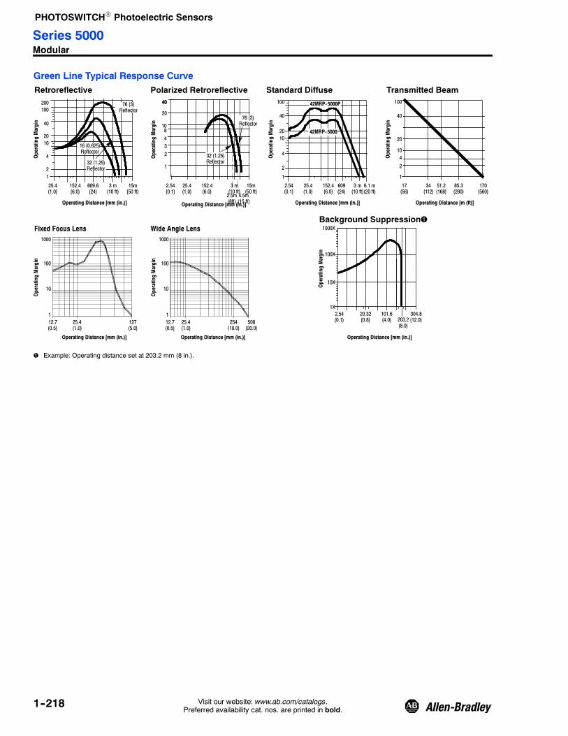
PHOTOSWITCHR Photoelectric Sensors
1--218 Visit our website: www.ab.com/catalogs.Preferred availability cat. nos. are printed in bold.
Green Line Typical Response CurveRetroreflective Polarized Retroreflective
1
20
200
Operating Distance [mm (in.)]
OperatingMargin
25.4(1.0)
4
10
3 m(10 ft)
OperatingMargin
20
40
OperatingMargin
152.4(6.0)
Operating Distance [mm (in.)]
100
40
20
1
40
10
4
2
15m(50 ft)
Standard Diffuse
1
2
152.4(6.0)
15m(50 ft)
4
152.4(6.0)
609.6(24)
Operating Distance [mm (in.)]
3 m(10 ft)
OperatingMargin
Transmitted Beam40
2.54(0.1)
10
2
25.4(1.0)
609(24)
51.2(168)
170(560)
34(112)
17(56)
Operating Distance [m (ft)]
42MRP-5000
42MRP-5000P100
3
25.4(1.0)
4.5m(15 ft)
2.5m(8ft)
6.1 m(20 ft)
3 m(10 ft)
2.54(0.1)
8
100
40
20
1
410
2
85.3(280)
76 (3)Reflector
16 (0.625)Reflector
32 (1.25)Reflector
76 (3)Reflector
32 (1.25)Reflector
Operating Distance [mm (in.)]
OperatingMargin
12.7(0.5)
OperatingMargin
127(5.0)
508(20.0)
Operating Distance [mm (in.)]
25.4(1.0)
1
100
10
1000
12.7(0.5)
254(10.0)
25.4(1.0)
1
100
10
1000
Fixed Focus Lens Wide Angle LensBackground Suppression
Operating Distance [mm (in.)]
OperatingMargin
1X
100X
10X
1000X
101.6(4.0)
304.8(12.0)
20.32(0.8) 203.2
(8.0)
2.54(0.1)
Example: Operating distance set at 203.2 mm (8 in.).
Series 5000Modular

PHOTOSWITCHR Photoelectric Sensors
1--219Visit our website: www.ab.com/catalogs.Preferred availability cat. nos. are printed in bold.
Analog Output Typical Response Curve
Operating Distance [m (ft)] Operating Distance [m (ft)]Operating Distance [m (ft)] Operating Distance [m (ft)]
Retroreflective
DCVoltage
DCCurrent(mA
DCVoltage
Standard Diffuse
DCCurrent(mA)
Voltage Output Slope Current Output Slope Voltage Output Current Output
PositiveSlope
NegativeSlope
15 in. x 15 in.3 m 7590
1
7
10
0.3(1)
3.3(11)
0.9(3)
8
6
4
2
4.5(15)
1.5(5)
9
5
3
0
2.1(7)
2.7(9)
3.9(13)
1
7
10
8
6
4
2
9
5
3
14
20
3.3(11)
0.9(3)
16
12
8
4
4.5(15)
1.5(5)
18
10
6
0
2.1(7)
2.7(9)
3.9(13)
2
14
20
152mm(6in)
16
12
8
4
1.5(5)
18
10
6
2
0.6(2)
0.9(3)
1.2(4)
0.3(1)
PositiveSlope
NegativeSlope
15 in. x 15 in.3 m 7590
0.9(3)
1.5(5)
0.3(1)
1.2(4)
0 0.6(2)
0
0 0
PositiveSlope
NegativeSlope Positive
SlopeNegativeSlope
Infrared Glass FO/Fixed Focus/Wide Angle DiffuseVoltage Output Current Output
Operating Distance— [mm (in.)] Operating Distance— [mm (in.)]
DCVoltage
DCCurrent(mAPositive
SlopeNegativeSlope
1
7
10
100(3.94)
300(11.81)
8
6
4
2
400(15.75)
9
5
3
0
200(7.87)
14
20
16
12
8
4
18
10
6
02
PositiveSlope
NegativeSlope
100(3.94)
300(11.81)
400(15.75)
200(7.87)
Product Selection Guidelines
1. Select photohead (see pages 1--220 to 1--225).
2. Select power base (see page 1--226).
3. Select output module for green line models only (see page 1--226).
4. Select plug-in control function optional module on page 1--226 (green models only).
Series 5000Modular

PHOTOSWITCHR Photoelectric Sensors
1--220 Visit our website: www.ab.com/catalogs.Preferred availability cat. nos. are printed in bold.
Red Line Product Selection [mm (in.)]1. Select Photohead.
Sensing ModeSensing Distance
[mm (in.)]Output
EnergizedOutput TypeCapacity
Response Time
Cat. No.Sensor Output
Red Line—Retroreflective/StandardDiffuse
Field of View: 3_Emitter LED: Infrared 880 nm
Object toBe Sensed
50.8 mm…6 m(2 in…20 ft) with
76 (3)Reflector
50.8 mm…1.5 m(2 in…5 ft) withWhite Paper
Light/DarkSelectable
EM Relay (SPDT)2.0 A--120V AC1.0 A--240V AC
5 ms
On 10 msOff 15 ms 42LRC--5000
AC/DC Solid StateFET (SP--N.O.)
30 mA0…120V AC/DC
1 ms 42LRC--5010
AC Solid State TRIAC(SP--N.O.)0.75 A
240V AC cont.
8 ms 42LRC--5020
Red Line—Polarized RetroreflectiveField of View: 3_Emitter LED: Visible Red 660 nm
Object toBe Sensed
50.8 mm…6 m(2 in…20 ft) with76 (3) Reflector
Light/DarkSelectable
EM-Relay (SPDT)2.0 A--120V AC1.0 A--240V AC
5 ms
On 10 msOff 15 ms 42LRC--5200
AC/DC Solid StateFET (SP--N.O.)
30 mA0…120V AC/DC
1 ms 42LRC--5210
AC Solid StateTRIAC (SP--N.O.)
0.75 A240V AC cont.
8 ms 42LRC--5220
Blue Line Product Selection [mm (in.)]
Blue Line—RetroreflectiveField of View: 2.5_Emitter LED: Infrared 880 nm
Object toBe Sensed
50.8 mm…10 m(2 in…33 ft) with76 (3) Reflector
Light/DarkSelectable
NPN and PNP100 mA 1 ms 42DRU--5000
Blue Line—Polarized RetroreflectiveField of View: 2.5_Emitter LED: Visible Red 660 nm
Object toBe Sensed
50.8 mm…6 m(2 in…20 ft) with76 (3) Reflector
Light/DarkSelectable
NPN and PNP100 mA 1 ms 42DRU--5200
Blue Line—Standard DiffuseField of View: 3_Emitter LED: Infrared 880 nm
Object toBe Sensed Long Range:
50.8 mm…2.1 m(2 in…7 ft) withWhite Paper
Light/DarkSelectable
NPN and PNP100 mA 1 ms 42DRP--5000
Add Sensor and Output for total response time.
Refer to page 1--226 for cordsets and accessories.
Series 5000Red Line/Blue Line

PHOTOSWITCHR Photoelectric Sensors
1--221Visit our website: www.ab.com/catalogs.Preferred availability cat. nos. are printed in bold.
Blue Line Product Selection [mm (in.)] (continued)
Sensing Mode Sensing Distance Output EnergizedOutput TypeCapacity Response Time Cat. No.
Blue Line—Large Aperture Fiber OpticField of View: Depends on fiber optics or lens
selected or lens typeEmitter LED: Infrared 880 nm
Object toBe Sensed
Depends on FiberOptic selected.
Light/DarkSelectable
NPN and PNP100 mA 1 ms 42DRA--5000FO
Blue Line Product Selection [mm (in.)] (continued)
Sensing Mode
SensingDistance[mm (in.)]
OutputEnergized Output
TimingResponseTime Cat. No.Function Range
Blue Line—Background Suppressionwithout Timing
Field of View: 3_Emitter LED: Infrared 880 nm
Background
Object toBe Sensed
SuppressionPoint
AdjustmentRange
50.8 (2) to63.5…304.8(2.5…12)
Light/DarkSelectable NPN & PNP — —
5 ms
42DBS--5000
Blue Line—Background Suppressionwith Timing
Field of View: 3_Emitter LED: Infrared 880 nm
Background
Object toBe Sensed
SuppressionPoint
AdjustmentRange
50.8 (2) to63.5…304.8(2.5…12)
Light/DarkSelectable NPN & PNP
SelectableOn DelayOff Delay
On & Off DelayDelayed One-shot
One-shot0…1.5 s0…15 sSelectable
42DBS--5100
Refer to page 1--226 for cordsets and accessories.
Series 5000Blue Line

PHOTOSWITCHR Photoelectric Sensors
1--222 Visit our website: www.ab.com/catalogs.Preferred availability cat. nos. are printed in bold.
Green Line Product Selection [mm (in.)]
Sensing ModeSensing Distance
[mm (in.)] Output EnergizedSensor Response
Time Cat. No.
Green Line—RetroreflectiveField of View: 2.5_Emitter LED: Infrared 880 nm
Object toBe Sensed
50.8 mm…10 m(2 in…33 ft) with76 (3) Reflector
Light/Dark Selectable 1 ms 42MRU--5000
Green Line—Polarized RetroreflectiveField of View: 2.5_Emitter LED: Visible Red 660 nm
Object toBe Sensed
50.8 mm…6 m(2 in…20 ft) with76 (3) Reflector
Light/Dark Selectable 2.5 ms 42MRU--5200
Green Line—Standard DiffuseField of View: 3_Emitter LED: Infrared 880 nm
Object toBe Sensed Short Range: 50.8 mm…
3 m (2 in.…10 ft) withWhite Paper
Light/Dark Selectable 2.5 ms 42MRP--5000
Green Line—Long Range DiffuseField of View: 3_Emitter LED: Infrared 880 nm
Object toBe Sensed Long Range: 50.8 mm…
4.8 m (2 in…16 ft) withWhite Paper
Light/Dark Selectable 2.5 ms 42MRP--5000P
Add Sensor and Output for total response time.
Refer to page 1--226 for cordsets and accessories.
Series 5000Green Line

PHOTOSWITCHR Photoelectric Sensors
1--223Visit our website: www.ab.com/catalogs.Preferred availability cat. nos. are printed in bold.
Green Line Product Selection [mm (in.)] (continued)1. Select Photohead (continued).
Sensing ModeSensing Distance
[mm (in.)] Output EnergizedSensor Response
Time Cat. No.
Green Line—Transmitted Beam ReceiverField of View: 3_Emitter LED: Infrared 880 nm
Object toBe Sensed
25.4 mm…171 m(1 in…560 ft) Light/Dark Selectable 5 ms
42MRR--5000
Order one receiver and onelight source
Green Line—Transmitted Beam Light SourceField of View: 3_Emitter LED: Infrared 880 nm
Object toBe Sensed
25.4 mm…171 m(1 in…560 ft) — N/A
42MRL--5000
Order one receiver and onelight source
Green Line—Large Aperture Fiber OpticField of View: Determined by fiber optics
or lens typeEmitter LED: Infrared 880 nm
Object toBe Sensed
Depends on Fiber Opticselected. Light/Dark Selectable 2.5 ms 42MRA--5000FO
Green Line—Fixed FocusEmitter LED: Infrared 880 nm
Objectto beSensed
5.08 mm…172 m(0.2 in…564 ft ) Light/Dark Selectable 2.5 ms 42MRA--5000FF
Green Line—Wide Angle DiffuseEmitter LED: Infrared 880 nm
Objectto beSensed
5.08 (0.2)…508 (20) Light/Dark Selectable 2.5 ms 42MRA--5000WA
Prewired for use with output 8--593 only.
Refer to page 1--226 for cordsets and accessories.
Series 5000Green Line

PHOTOSWITCHR Photoelectric Sensors
1--224 Visit our website: www.ab.com/catalogs.Preferred availability cat. nos. are printed in bold.
Green Line Product Selection [mm (in.)] (continued)1. Select Photohead (continued).
Sensing ModeSensing Distance
[mm (in.)]Output
Energized
Timing SensorResponseTime Cat. No.Function Range
Background
Green Line—Background Suppressionwithout Timing
Field of View: 3_Emitter LED: Infrared 880 nm
Object toBe Sensed
Suppression PointAdjustment Range
50.8 (2) to63.5…304.8(2.5…12)
Light/DarkSelectable — — 5 ms 42MBS--5000
Background
Green Line—Background Suppressionwith Timing
Field of View: 3_Emitter LED: Infrared 880 nm
Object toBe Sensed
Suppression PointAdjustment Range
50.8 (2) to63.5…304.8(2.5…12)
Light/DarkSelectable
Selectable OnDelay
Off DelayOn & Off DelayOne-shot
Delayed One-shot
0…1.5 s0…15 sSelectable
5 ms 42MBS--5100
Analog Output Product Selection [mm (in.)]1. Select Photohead.
Sensing ModeSupplyCurrent Sensing Distance Analog Output
Output TypeCapacity
ResponseTime Slope Cat. No.
Analog Output—RetroreflectiveField of View: 3_Emitter LED: Infrared 880 nm
Object toBe Sensed
70 mA600 mm (2 ft)…Total: 4.6 m (15 ft)Linear 4.0 m (13 ft)
Voltage1…10V DC Two Adjustable
Set Points NPN100 mA (30V
Max)
100 msSelectablePositive orNegative
42DRU--5400
Current 1…20 mA
Prewired for use with output 8--593 only.
Time needed for full analog swing.
Refer to page 1--226 for cordsets and accessories.
Series 5000Green Line/Analog Output

PHOTOSWITCHR Photoelectric Sensors
1--225Visit our website: www.ab.com/catalogs.Preferred availability cat. nos. are printed in bold.
Analog Output Product Selection [mm (in.)] (continued)
Sensing ModeSensing Distance
[mm (in.)] Analog OutputOutput TypeCapacity
ResponseTime Slope Cat. No.
Analog Output—Standard DiffuseField of View: 3_Emitter LED: Infrared 880 nm
Object toBe Sensed 150 (6)…
Total: 1.5 m (5 ft)Linear: 1.2 m (4 ft)
Voltage 1…10V DC
Current 1…20 mA
Two Adjustable SetPoints NPN
100 mA (30V max)100 ms
SelectablePositive orNegative
42DRP--5400
Analog Output—Large Aperture FiberOptic
Field of View: Depends on fiber optics(refer to fiber opticsection) or lens type
Emitter LED: Infrared 880 nm
Object toBe Sensed
Depends on FiberOptic selected.
Voltage 1…10V DCCurrent 1…20 mA
Two Adjustable SetPoints NPN
100 mA (30V max)100 ms
SelectablePositive orNegative
42DRA--5400FO
Analog Output—Fixed FocusEmitter LED: Infrared 880 nm
Objectto beSensed
5.08…101(0.2…4)
Voltage 1…10V DCCurrent 1…20 mA
Two Adjustable SetPoints NPN
100 mA (30V max)100 ms
SelectablePositive orNegative
42DRA--5400FF
Analog Output Product Selection [mm (in.)] (continued)1. Select Photohead.
Sensing ModeSensingDistance Analog Output
Output TypeCapacity
ResponseTime Slope Cat. No.
Analog Output—Wide Angle DiffuseEmitter LED: Infrared 880 nm
Objectto beSensed
5.08 (0.2 in.)…152 mm (6 in.)
Voltage 1…10V DCCurrent 1…20 mA
Two Adjustable SetPoints NPN
100 mA (30V max)100 ms
SelectablePositive orNegative
42DRA--5400WA
Time needed for full analog swing.
Refer to page 1--226 for cordsets and accessories.
Series 5000Analog Output

PHOTOSWITCHR Photoelectric Sensors
1--226 Visit our website: www.ab.com/catalogs.Preferred availability cat. nos. are printed in bold.
Power Base Product Selection [mm (in.)]
2. Select Power Base.
Style Operating Voltage Supply Current Cat. No.
Red Line
Terminal120V AC, 50/60 Hz 2V A 42LTB--5000
240V AC, 50/60 Hz 4V A 42LTB--5001
Cable 120V AC, 50/60 Hz 2V A 42LCB--5000
Blue Line
Terminal10…30V DC 35 mA
42DTB--5000
Cable 42DCB--5000
Operating Voltage Supply Current
Cat. No.
Terminal Style Mini QD Style
Green Line
102…132V AC, 50/60 Hz 2V A 42MTB--5000 42MTB--5000QD5--1
204…254V AC, 50/60 Hz 4V A 42MTB--5001 —
40…54V AC/DC, 50/60 Hz
1V A
42MTB--5002 —
20…30V AC, 50/60 Hz 42MTB--5003 —
20…30V DC 42MTB--5004 42MTB--5004QD4--1
Operating Voltage Supply Current Connection Type Cat. No.
Analog Output Line
All sensing modes 22…28V DC70 mA maximum Screw Terminal 42DTB--5000
70 mA maximum 3 m 300V Cable 42DCB--5000
3. Select Output module (green line models only) (required).
4. Select plug-in control function optional module (green line models only).
Cordsets and Accessories
Description Cat./Page No. Description Cat. No. Description Cat. No.
Terminal Chambers 8--1 Right Angle Bracket 60--1785 76 mm (3 in.) Diameter Reflector 92--39
Screw Terminal 42MTB--5000 Conduit Adaptor 1/2 inchNPT 60--2213 32 mm (1.25 in.) Diameter
Reflector 92--47
5-pin DC Mini QD 42MTB--5000--QD5--1 Armored Cable Adaptor 60--1577 Heavy Duty Protective Guard 60--2083
Flexi-mount MountingAssembly 60--2014 Limit Switch Type
Mounting Assembly 60--2230 Heavy Duty Mounting Assembly 60--1748
Prewired for use with output 8--593 only.
Series 5000Power Base

PHOTOSWITCHR Photoelectric Sensors
Series 4000B
1--227Visit our website: www.ab.com/catalogs.Preferred availability cat. nos. are printed in bold.
Features
S Harsh duty package
S Screw terminal connections
S Long-range sensing modes
S Plug-in logic and output modules
S Both DC and AC/DC operation
S Selectable light/dark operation
SpecificationsEnvironmentalCertifications UL Listed, CSA Approved
Operating Environment NEMA 3, 4, 12, 13; IP66
Operating Temperature [C (F)] --40…+57° (--40…+135°)
Vibration 10…55 Hz, 1 mm amplitude, meets or exceeds IEC 60947--5--2
Shock 30 g with 1 ms pulse duration, meets or exceeds IEC 60947--5--2
Relative Humidity 5…90%
OpticalSensing Modes Retroreflective, polarized retroreflective, diffuse, transmitted beam
Sensing Range See Product Selection table on page 1--230
Field of View See Product Selection table on page 1--230
Light Source Visible red LED (660 nm), infrared LED (880 nm)
LED Indicators See User Interface below
Adjustments Sensitivity adjustment potentiometer
ElectricalVoltage See Product Selection table on page 1--230
Current Consumption See Product Selection table on page 1--230
Sensor Protection False pulse
OutputsResponse Time 5 ms plus plug-in module delay
Output Type EM relay, TRIAC, FET, PNP/NPN
Output Mode Light or dark operate selectable
Output Current Determined by plug-in module, see Product Selection table onpage 1--230
Output Leakage Current 1 μA max
MechanicalHousing Material Norylr
Lens Material Acrylic, glass for polarized sensor
Connection Types Nickel-plated screw terminal
Supplied Accessories 8--670 DPDT relay module
Optional Accessories Mounting brackets, reflectors, cordsets
User Interface Panel
Label Color State Status
Power YellowOFF Sensor not powered
ON Sensor powered

PHOTOSWITCHR Photoelectric Sensors
Series 4000B
1--228 Visit our website: www.ab.com/catalogs.Preferred availability cat. nos. are printed in bold.
Optional Timing and Logic ModulesThese plug-in modules can be added to any series 4000B Photoelectric sensor.
Function
Adjustable Time Delay(s)
Adjustable Dwell (s) Cat. No.On Off
One-shot — —0.040…0.250 60--1612--1
0.5…15 60--1612--2
On and/or Off Delay0.05…1.0 0.05…1.5
—60--1613
0.5…10 0.5…15 60--1614
Delayed One-shot0.10…1.5
—0.040…0.250 60--1625
1.0…15 0.040…0.250 60--1626
Motion Detector —0.05…1.5
—60--1660
0.5…15 60--1661
Preset Counter 2…999 Counts 0.040…0.250 60--1716
Wiring DiagramsAll Sensing Modes ExceptTransmitted Beam Light Source
Optional Plug-InTiming and Logic Module
Power Supply
Model 4000B: 120V AC, 50/60 HzModel 4001B: 240V AC, 50/60 HzModel 4002B: 48V AC, 50/60 Hz
Model 4003B: 24V AC/DC, 50/60 HzModel 4200B: 120V AC, 50/60 Hz
D
Alignment Indicator
Light/DarkSelection Switch
Output RelayContacts
Output RelayContacts
Plug-In Output Relay
Sensitivity Adjustment
L
Alignment Test PointsRelay Pull-in: 2.5V DCRelay Drop-Out: 2.0V DC
Optimum 5.0V DC
L11NC1NO1C
L22NC2NO2C
Additional Output Connections
#8--651, 8--652,and 63--116 #63--115
2C
2N0
Load 1C
1N0
--
+
Note: Details regarding connection of Allen-Bradley Series 4000B sensors to Allen-Bradley Programmable Controllers can be found inpublication 42-2.0.
Transmitted Beam Light Source
Power Supply
L1 L2
Model 4000B: 120V AC 50/60 HzModel 4001B: 230V AC 50/60 Hz
No ConnectionNo Connection
Power Indicator

PHOTOSWITCHR Photoelectric Sensors
Series 4000B
1--229Visit our website: www.ab.com/catalogs.Preferred availability cat. nos. are printed in bold.
Approximate Dimensions [mm (in.)]
2(50.8)
LEDIndicator
Notes
1. Sensor may be mounted without bracket,either using 3, 1/4--20NC mtg. holes or on a3/4 in. threaded pipe, thread pitch3/4--14NPSM.
2. Bracket allows 360°adjustment.
3. Screws included with mounting bracket.
Optional Mounting BracketP/N 60--1479
Adjustment Slots86.4(3.4)
1/4 - 20NC x 5/8 LGFlanged Hex Head
3 Mounting Holes120° Apart In Sensor
3/4 -- 14NPSM50.8 (2) Dia.Bolt Circle
7.1(0.281)
17.5(0.687)
25.4 (1)
247.6(9.75)
61.9(2.437)
90.5(3.562)
146(5.75)
203.2(8)
79.4(3.125) Dia.
ATTENTION
DO NOT use lockwashers with supplied whiz-lock mounting screws.
Typical Response CurveRetroreflective Polarized Retroreflective
1
20
200
Operating Distance [mm (in.)]
OperatingMargin
4
10
0.3m(1 ft)
OperatingMargin 20
40
OperatingMargin
Operating Distance [mm (in.)]
1000
400
20
1
40
10
4
2
15m(50 ft)
Standard Diffuse
1
2 4
152.4(6.0)
Operating Distance [mm (in.)]
OperatingMargin
Transmitted Beam
40
2.54(0.1)
10
2
25.4(1.0)
0.6m(2 ft)
82m(270 ft)
274m(900 ft)
55m(180 ft)
10%
Operating Distance [ m ( ft)]
100
76.2(3)
6m(20 ft)
3m(10 ft)2.74m(9 ft)
100
40X
20
1
5
10
2
137m(450 ft)
3
400
1000
1.5m(5 ft)
9.1m(30 ft)
4.5m(15 ft)
100
0.3m(1 ft)
15m(50 ft)
2.54(0.1)
76.2(3)
3m(10 ft)
1.5m(5 ft)
76 (3)Reflector 76 (3)
Reflector 200100
40
6m(20 ft)
3

PHOTOSWITCHR Photoelectric Sensors
Series 4000B
1--230 Visit our website: www.ab.com/catalogs.Preferred availability cat. nos. are printed in bold.
Product Selection1. Select sensor.
Sensing ModeOperating Voltage/Power Consumption
Sensing Range[mm (in.)]
OutputEnergized
SensorResponse Time Cat. No.
Retroreflective
Field of View: 1.5_Emitter LED: Infrared 940 nm
Object toBe Sensed
102…132V AC/2V A
50.8 mm…10.6 m(2 in…35 ft)
Light/DarkSelectable 5 ms
42RLU--4000B
195…253V AC/2V A 42RLU--4001B
40…58V AC/2V A 42RLU--4002B
18…28V AC/DC/2V A20…32V DC 42RLU--4003B
Series 4000B Polarized Retroreflective
Field of View: 2_Emitter LED: Visible Red 660 nm
Object toBe Sensed
102…132V AC/2 A
50.8 mm…7 m(2 in…23 ft)
Light/DarkSelectable 5 ms 42RLU--4200B
Standard Diffuse
Field of View: 4_Emitter LED: Infrared 940 nm
Object toBe Sensed 102…132V AC/
2V A50.8 mm…3.6 m(2 in…12 ft)
Light/DarkSelectable 5 ms 42RLP--4000B
Transmitted Beam
Field of View: 3_Emitter LED: Infrared 940 nm
Light sources and receivers must beordered separately. Any light source iscompatible with any receiver.
Object toBe Sensed 102…132V AC, 50/60 Hz/
2V A50.8 mm…274 m(2 in…900 ft)
Light/DarkSelectable 5 ms 42RLR--4000B
2. Select optional plug-in timing and logic module, page 1--227.
3. Select optional plug-in output module.
Sensing Mode Type Max Load Current Output Response Time Cat. No.
All sensing modes
DPDTEM-Relay (included)
5 A, 120V AC2.5 A, 240V AC
10 ms On15 ms Off 8--670
SP-N.O.AC TRIAC 1 A, 265V AC, 20 mA min 8 ms 8--651
SP-N.O.AC/DC FET 30 mA, 0…120V AC/DC 1 ms 8--652
Open CollectorNPN 250 mA, 30V DC
1 ms63--115
DC VoltageOutput Adaptor 30 mA, 17V DC 63--116
Add sensor response time and output response time for total response time.
8--670 relay output module supplied with sensor.

PHOTOSWITCHR Photoelectric Sensors
1--231Visit our website: www.ab.com/catalogs.Preferred availability cat. nos. are printed in bold.
Fiber optic sensors permit theattachment of “light pipes” called fiberoptic cables. Light emitted from thesource is sent through transparentfibers in the cables and emerges at theend of the fiber. The transmitted orreflected beam is then carried back tothe receiver through different fibers.Ideal for sensing small objects, fiberoptic cables can be mounted inlocations that would otherwise beinaccessible to photoelectric sensors.Other characteristics/advantages offiber optic sensors include:
S Some glass fiber optic tips have theability to withstand high temperatures(up to 482°C (900°F))
S Withstand extreme shock andvibration
S Often have the fastest responsetimes
S Immunity to electrical interference(EMI, RFI).
Fiber Optic Cables—TypesFiber optic cables can be made of glassor plastic and categorized as eitherindividual (transmitted beam) orbifurcated (diffuse).
Glass fiber optic cables contain multiplestrands of very thin glass fiber that arebundled together in a flexible sheath.Typically more durable than their plasticcounterparts, glass fiber optic cableswill withstand much higher
temperatures; glass fiber optic cableswith a stainless steel sheath are ratedup to 260°C (500°F). Special glasscables can be obtained withtemperature ratings of up to 482°C(900°F). Most glass cables areavailable with a choice of PVC orflexible stainless steel sheath. WhilePVC-sheathed cables are typically lessexpensive, stainless steel sheathingoffers greater durability and allows thecables to operate in highertemperatures. Glass fibers can be usedwith infrared or visible LED lightsources.
Light transmission is maximized with athicker bundle diameter. It is alsoimportant to note that attenuationincreases as fiber optic cable lengthincreases. For further details, see theApplication Recommendations sectionon page 1--234 .
Plastic fiber optic cables areconstructed of a single acrylicmonofilament and, since plastic fibersabsorb infrared light, they are mostefficient when used with visible red LEDsources. It is recommended that plasticfiber optic cables are used with visiblelight sources. Considered less durablethan glass cables, plastic fibers aregenerally less expensive and can beused in applications where continuousflexing of the cable is required. For thatreason, coiled plastic cables are alsoavailable for such applications.
General InformationSensor and Sensing TipSelection page 1--232 and 1--233. . . . .
Glass Fiber Optic CablesApplicationRecommendations page 1--234. . . . . . .Large Aperture Fibers page 1--235. . . .Small Aperture Fibers page 1--251. . . .Custom FiberConfigurator page 1--258. . . . . . . . . . . .Sensing Tip Drawings page 1--260. . . .Standard Bundle Sizes page 1--268. . .Accessories page 1--269. . . . . . . . . . . .
Plastic Fiber Optic CablesApplicationRecommendations page 1--270. . . . . . .Small Aperture Fibers page 1--271. . . .Miniature Aperture Fibers page 1--277.Special Purpose Fibers page 1--280. . .Custom FiberConfigurator page 1--281. . . . . . . . . . . .Sensing Tip Drawings page 1--283. . . .Standard Bundle Sizes page 1--286. . .Accessories page 1--287. . . . . . . . . . . .Cross Reference page 1--292. . . . . . . .
Fiber Optic CablesIntroduction

PHOTOSWITCHR Photoelectric Sensors
1--232 Visit our website: www.ab.com/catalogs.Preferred availability cat. nos. are printed in bold.
Selection Process1. Determine the sensing mode
S Transmitted beam (two separatecables required)G Greater distance from sensing
tip to the objectG Reflectivity of the object is lowG Generally darker colors reflect
less light.
S Diffuse (one bifurcated cable)G Distance from sensing tip to the
object is smallG Reflectivity of the object is highG Generally lighter colors reflect
more light.2. Choose between glass or plastic
fiber optic cables
S GlassG Higher temperature rating (up
to 482°C (900°F) possible)G Used with infrared or visible red
light sourcesG More expensive.
S PlasticG Typically used for visible light
sourcesG Lower temperature applications
(lower than 70°C (158°F))
G Less expensive.
3. Mechanical considerations
S Glass has a more restrictive bendingradius.
S Select sensing tip configurationbased on mounting space availabilityG Threaded tip versus ferruledG Straight tip versus 45° or 90°
bendG Straight tip with light exiting at
90°.
4. Select fiber bundle size for theapplication.
S The smaller the bundle size, thesmaller the light spot size for seeingsmaller objects.
S The larger the bundle size, thegreater the sensing distance
5. Cable length
S Determine distance from sensor toobject including required bendingradii
S Longer (custom length) cables haveshorter sensing distances due to lightloss
G Light loss is approximately 6%per foot for glass and 3% forplastic
S Use of extended range lensassemblies significantly increasessensing distance.
Custom Fiber Optic CablesRockwell Automation/Allen-Bradley canprovide custom glass fiber optic cablesto meet nearly any applicationrequirement.
Typical cable modifications include:
S Custom lengths up to 15.2 m (50 ft)
S Custom temperature ratings up to482_C (900_F) applies to glass fiberoptic cables
S Custom configurations includingmultiple sensing tips
S Custom sensing end tips— nearlyany modification is possible
S Reference pages 1--258…1--259 forglass and 1--281…1--282 for plastic.
Note: For more information contactproduct support at 1.440.646.5800.
ATTENTIONFiber optic cables are not recommended for explosion-proof applications in hazardousenvironments. The fiber optic cable can provide a path for explosive fumes to travel from thehazardous area to the safe area.
Sensing ModesThe standard photoelectric sensors,fiber optic sensors are offered in twosensing modes: transmitted beam anddiffuse. Reflective sensing can beaccomplished in a diffuse mode orretroreflective mode.
Standard diffuse sensing with fiberoptic cables is similar to sensing withlensed photoelectrics. When adjusted tomaximum sensitivity these sensors,using bifurcated fiber optic cables, candetect extremely small targets.
Individual fiber optic cables may beused for more specialized diffuse modeapplications. For instance, aiming thetwo separate sensing tips of the cablesat the target can create sharp cutoff,fixed focus and mechanicallyconvergent sensing modes.
Bifurcated Cable (Diffuse/Retroreflective)
To thesensor Target
Standard retroreflective sensing ispossible with fiber optics, but polarizedretroreflective sensing is not. In someapplications, it will be necessary to
reduce the sensitivity of the sensor toprevent diffuse detection of the target.
Transmitted beam sensing, the mostreliable sensing mode, requires two
individual fiber optic cables. Targets aredetected when they break the light pathestablished between the emitter andreceiver cables.
Fiber Optic CablesIntroduction

PHOTOSWITCHR Photoelectric Sensors
1--233Visit our website: www.ab.com/catalogs.Preferred availability cat. nos. are printed in bold.
Individual Cable (Transmitted Beam)
To thesensor
To thesensorTarget
Sensing End Tip SelectionOne of the most important decisions tobe made when selecting fiber opticcables is the sensing end tipconfiguration. Among the manyconsiderations:
S Size of the object to be sensed
S Rate of travel of the target object
S Distance to the object
S Mounting options
S Environmental conditions
S Moving parts surrounding the object
S Sensing mode
Based on these factors, there are manysensing tips to select from offering
various fiber diameters and arrays,bending radii, threaded and smoothbody configurations, etc. The followingpages are designed to assist in theselection of the proper sensing end tipfor the application. Once a selectionhas been made, proceed to the fiberoptic cables section to select theappropriate fiber optic cable partnumber.
45FVL/45FSL Light Source Selector Guide for Color Contrast Sensing
Background
Target
White Yellow Orange Red Green Blue Black
White B B B R R R
Yellow B G G R R R
Orange B G G G G R
Red B G G R B R
Green R R G R B G
Blue R R G B B B
Black R R R R G B
R = Red; B = Blue; G = Green45CLR ColorSight sensor suggested for shades of same color.
Note: White LED light source can be used selectively in place of red, blue and green.
Cork Detection with Work Piece Detection withBifurcated Fiber Optic Cables Individual Fiber Optic Cables
Fiber Optic CablesIntroduction

PHOTOSWITCHR Photoelectric Sensors
1--234 Visit our website: www.ab.com/catalogs.Preferred availability cat. nos. are printed in bold.
Application Recommendations1. Many glass fiber optic cables are
available with different glass fiberbundle diameters.
Larger diameter bundles containmore fibers to carry light betweenthe sensor and application. Thesecables will generally offer longersensing ranges.
Smaller diameter bundles providegreater resolution and the ability todetect smaller targets.
2. Glass fiber optic cables can beapplied in high shock and vibrationapplications, but secure the cablesto prevent excess flexing. Do notuse glass cables in applicationswhere they are constantly flexing.They will break. Plastic fiber opticcables provide better performancein these applications.
3. Avoid sharp bends. The individualglass fibers in the cable can bebroken. Don’t exceed the followingbend tolerances with PVC sheathedcables:
Minimum Cable Bend Radius
Bundle Diameter[mm (in.)]
Minimum BendRadius
[mm (in.)]
0.68 (0.027) 12.7 (0.50)
1.16 (0.046) 12.7 (0.50)
1.6 (0.063) 15.8 (0.625)
2.28 (0.090) 15.8 (0.625)
3.17 (0.125) 19.0 (0.75)
3.96 (0.156) 25.4 (1.0)
4.57 (0.180) 31.7 (1.25)
4. Glass fiber optic cables cannot becut, spliced or repaired.
5. Glass fiber optic cables tip cannotbe bent. Only special plastic fiberoptic cable sensing end tips can bebent as specified in the SelectionGuide. When using bendable endtips, bend should not be attemptedcloser than 19 mm (0.75 in.) to thesensing end of the cable.
6. Some applications call for glassfiber optic cables to be used toisolate the sensor from highvoltage. Custom cables with specialnonconductive components must beordered for these applications.
7. X-RAY or GAMMA radiation willcause glass fibers to eventuallybecome opaque. Custom cablesconstructed with special opticalquartz fibers must be ordered foruse in areas with high radiation.
8. Use Transmitted Beam sensing insubmerged applications whenpossible. Spiral-wound stainlesssteel sheathing is generally notsuitable for wet applications. Fiberoptic cables with PVC sheathingshould be used for theseapplications.
9. A glass fiber optic sensor with abifurcated cable can provideretroreflective or diffuse sensingdepending upon the distance to thetarget and the sensitivity adjustmenton the sensor. If the sensor and
cable are to be used forretroreflective sensing, thesensitivity of the sensor must beadjusted low enough to avoidunwanted diffuse response from thetargets to be sensed.
10. Glass fiber optic cables have a widefield of view, typically 82_. Asmaller field of view can beachieved by attaching an ExtendedRange Lens Assembly to thesensing end of the fiber. These lensassemblies will also increase theavailable sensing distance. Refer tothe Accessories section for moreinformation.
11. Most glass fiber optic cables haveround sensing tips with the glassfibers arranged in a circularconfiguration. Other cables such as43GT--FIS40SL offer sensing tipswith a rectangular shapedopening for the glass fibers,referred to as “slotted” cables (seeillustration below).
ControlInterfaceEnd Tip
SensingEnd Tip
Use these equivalent diameters todetermine the approximateperformance of slotted cables.
Slot Dimensions[mm (in.)]
Round SensingTip Equivalent
Diameter[mm (in.)]
2.5 x 0.5 (0.1 x 0.02) 1.2 (0.046)
0.5 x 2.5 (0.02 x 0.1) 1.2 (0.046)
5.1 x 0.25 (2.0 x 0.01) 1.2 (0.046)
9.7 x 0.8(0.382 x 0.032) 3.1 (0.125)
Formula:Approximate diameter = 1.128 x Length x Width
ATTENTIONFiber optic cables are not recommended for explosion-proof applications in hazardousenvironments. The fiber optic cable can provide a path for explosive fumes to travel from thehazardous area to the safe area.
Glass Fiber Optic CablesIntroduction

PHOTOSWITCHR Photoelectric Sensors
1--235Visit our website: www.ab.com/catalogs.Preferred availability cat. nos. are printed in bold.
Glass Fiber Optic Cables for usewith Large Aperture SensorsThe fiber optic cables on pages1--236…1--250 are for use with thelarge aperture sensors shown below.
42GxF--900x
Large Aperture Sensors:
42SRF--60xx42SRF--65xx
42GTGF--100x042GTGF--103x0 42xRx--5x00FO
42GxF--900x 42EF--G1xxA
42KL--G1xxx
Note: Nominal Sensing Distance
• Due to the variation between fiber optic cables, sensing distance can vary widely
• The sensing distance of bifurcated cables is measured with white paper (90% reflectivity). Other surfaces may beless reflective and therefore would have shorter sensing distances.
• The published numbers are based on extensive testing and are conservative
• The sensing distance of transmitted beam cables is measured from tip to tip
• Application considerations that effect distance• Sensor selected• Reflectivity of target• Environment• Accessories such as range extending lenses• Length of the cable
• Consult with product support for additional information.
All dimensions indicated are typical. The fiber optic cables on pages 1--236…1--250are for use with large aperture sensors as seen on the following pages:
Glass Fiber Optic CablesCables for Large Aperture Sensors [4.6 mm (0.187 in.)]
4.6 mm (0.187 in.) diameter fiber control tips
Large Aperture: 4.6 mm (0.187 in.) diameter

PHOTOSWITCHR Photoelectric Sensors
1--236 Visit our website: www.ab.com/catalogs.Preferred availability cat. nos. are printed in bold.
0 50 150100 200 250
42GxF--900x
Approximate Metric / Standard Distances
mm
in.42KL--G1xx 42EF--G1xxA
300120 2 64 8 10
Approximate Dimensions [mm (in.)]
SensingTip
Material
FiberBundleDiameter[mm (in.)]
SheathingMaterial Sensing Distance [mm] Cat. No.
13.4(0.53)
38.1(1.5)
7.9(0.31)
5/16 x 24UNFThread
Brass
3.2 (0.125)
StainlessSteel 43GR--TBB25SL
PVC 43GR--TBB25ML
1.6 (0.062)
StainlessSteel 43GR--TBB15SL
PVC 43GR--TBB15ML
4.0 (0.156)
StainlessSteel 43GR--TBB30SL
PVC 43GR--TBB30ML
2.5 x 0.5(0.1 x 0.02)E-W Slot
StainlessSteel 43GR--TBB40SL
PVC 43GR--TBB40ML
StainlessSteel
1.6 (0.062)
StainlessSteel 43GR--TBS15SL
PVC 43GR--TBS15ML
3.2 (0.125)
StainlessSteel 43GR--TBS25SL
PVC 43GR--TBS25ML
M6 x 1Thread
10.2(0.4)
11.2(0.44)5.8 (0.23)
StainlessSteel
2.3 (0.09)
StainlessSteel 43GR--TAS20SL
PVC 43GR--TAS20ML
#8-32Thread
13.4(0.53)
12.7(0.5)
4.5(0.18)
StainlessSteel
1.2 (0.046)
StainlessSteel 43GR--TFS10SL
PVC 43GR--TFS10ML
3/8 x 24 Thread
38.1(1.5)
12.7(0.5)
Brass 4.6 (0.180)
StainlessSteel 43GR--TGB33SL
PVC 43GR--TGB33ML
13.5(0.53)
15.2(0.6)7.9 (0.31)
5/16 x 24Thread
Brass 3.2 (0.125)
StainlessSteel 43GR--XDB25SL
PVC 43GR--XDB25ML
9.7 (0.38)
4.5 (0.18)
3.1 (0.12)
6.4R(0.25)
2.36 (0.09)
15.2(0.6)
12.7(0.5)
15.9 (0.63)
#8--32 Thread
StainlessSteel
1.2 (0.046)
StainlessSteel 43GR--TCS10SL
PVC 43GR--TCS10ML
Note: Standard length for glass fiber optic cables is 0.91 m (36 in.) tip to tip.
43GR Glass Fiber Optic CablesThreaded Bifurcated Cables for Large Aperture Sensors [4.6 mm (0.187 in.)]

PHOTOSWITCHR Photoelectric Sensors
1--237Visit our website: www.ab.com/catalogs.Preferred availability cat. nos. are printed in bold.
Approximate Dimensions [mm (in.)]
SensingTip
Material
FiberBundleDiameter[mm (in.)]
SheathingMaterial Sensing Distance [mm] Cat. No.
20.3(0.8)
7.5(0.3)
3.1 (0.12)
12.7(0.5)R
4.75(0.19)
27.9(1.1)
38.1(1.5)
15.9(0.63)
5/16 x 24Thread
Brass/StainlessSteel
3.2 (0.125)
StainlessSteel 43GR--TMC25SL
PVC 43GR--TMC25ML
1.6 (0.062)
StainlessSteel 43GR--TMC15SL
PVC 43GR--TMC15ML
StainlessSteel
3.2 (0.125)
StainlessSteel 43GR--TMS25SL
PVC 43GR--TMS25ML
12.7(0.5) R
14.0(0.55)
5/16 x 24Thread
28(1.1)
4.7 (0.18)
15.7(0.62)
38.1(1.5)
7.9(0.31)
Brass/StainlessSteel
3.2 (0.125)
StainlessSteel 43GR--TQC25SL
PVC 43GR--TQC25ML
2.5 x 0.5(0.1 x 0.02)E-W Slot
StainlessSteel 43GR--TQC40SL
PVC 43GR--TQC40ML
12.7(0.5) R
14.0(0.55)
38.1(1.5)
5/16 x 24Thread
28(1.1)
5.5(0.22) Dia.
18.3(0.72)
7.9(0.31)
StainlessSteel
4.0 (0.156)
StainlessSteel 43GR--TRC30SL
PVC 43GR--TRC30ML
20.6(0.81)
14.0(0.55)
27.0 (1.06)
3.1 (0.12)
5/16 x 24Thread
4.75 (0.187)
38.1 (1.5)
7.9(0.31) 12.7 (0.5)
StainlessSteel
3.2 (0.125)
StainlessSteel 43GR--TXC25SL
PVC 43GR--TXC25ML
19.1(0.75)
3.1 (0.12)15.8 (0.62)
9.7 (0.38)
45_
38.1 (1.5)
5/16 x 24Thread
4.75(0.187)7.4 (0.29) Stainless
Steel3.2 (0.125)
StainlessSteel 43GR--THC25SL
PVC 43GR--THC25ML
Note: Standard length for glass fiber optic cables is 0.91 m (36 in.) tip to tip.
43GR Glass Fiber Optic CablesThreaded Bifurcated Cables for Large Aperture Sensors [4.6 mm (0.187 in.)]

PHOTOSWITCHR Photoelectric Sensors
1--238 Visit our website: www.ab.com/catalogs.Preferred availability cat. nos. are printed in bold.
Approximate Dimensions [mm (in.)]
SensingTip
Material
FiberBundleDiameter[mm (in.)]
SheathingMaterial Sensing Distance [mm] Cat. No.
4.7 (0.19)Dia.
19(0.75)
5/16x24Thread
45°12.7(0.5) R
12.7(0.5)
38.1 (1.5)
7.9(0.31)
Brass/StainlessSteel
3.2 (0.125)
StainlessSteel 43GR--TKC25SL
PVC 43GR--TKC25ML
3.1 (0.12)
25.4(1.0)
5/16 x 24Thread
5.3(0.21)
13.9 (0.55)38.1(1.5)
7.9 (0.31)
Side View Sensing
StainlessSteel
2.3 (0.09)
StainlessSteel 43GR--TTS20SL
PVC 43GR--TTS20ML
1.2 (0.046)
StainlessSteel 43GR--TTS10SL
PVC 43GR--TTS10ML
3/8--24 Thread
57 (2.25)72 (2.85)
3.1 (0.12)7.1 (0.28) Dia.
51 (2.00)
3.0(0.12)
8.13(0.32)
25.4(1.0)
14.0(0.55) 12.7
(0.5)
StainlessSteel
51 x 0.25(2.0 x 0.01)(N--S)
StainlessSteel
Characterization not available at timeof publication
43GR--TUS46SL
PVC 43GR--TUS46ML
Note: Standard length for glass fiber optic cables is 0.91 m (36 in.) tip to tip.
43GR Glass Fiber Optic CablesThreaded Bifurcated Cables for Large Aperture Sensors [4.6 mm (0.187 in.)]

PHOTOSWITCHR Photoelectric Sensors
1--239Visit our website: www.ab.com/catalogs.Preferred availability cat. nos. are printed in bold.
Approximate Dimensions [mm (in.)]
SensingTip
Material
FiberBundleDiameter[mm (in.)]
SheathingMaterial Sensing Distance [mm] Cat. No.
7.5(0.3) 4.8 (0.19)
Dia.
12.7(0.5)
12.7(0.5)
StainlessSteel
3.2 (0.125)
StainlessSteel 43GR--FAS25SL
PVC 43GR--FAS25ML
4.8(0.19)
12.7(0.5)
27.0(1.06)7.5 (0.3)
StainlessSteel
3.2 (0.125)StainlessSteel 43GR--FBS25SL
3.2 (0.125) PVC 43GR--FBS25ML
25.5 (1.0)1.1 (0.04) Stainless
Steel0.7 (0.027)
StainlessSteel 43GR--MAS00SL
PVC 43GR--MAS00ML
1.5(0.06) Dia.
4.1(0.16) 12.7
(0.5)
25.5 (1.0)
StainlessSteel
1.2 (0.046)
StainlessSteel 43GR--MDS10SL
PVC 43GR--MDS10ML
35.6(1.4)
76(3.0)
7.9 (0.31) Dia2.36
(0.93) Dia
StainlessSteel
1.6 (0.062)
StainlessSteel 43GR--MHS15SL
PVC 43GR--MHS15ML
4.8(0.19)7.5
(0.3)3.1(0.12)
12.7(0.5)
12.7(0.5)
14.0(0.55)
1.1(0.04)
StainlessSteel
0.7 (0.027)
StainlessSteel 43GR--MVS00SL
PVC 43GR--MVS00ML
12.7(0.5) R
16.0(0.63)
20(0.8)
4.7(0.19)
7.5(0.3)
28(1.1)
StainlessSteel
3.2 (0.125)
StainlessSteel 43GR--FIS25SL
PVC 43GR--FIS25ML
3.1 (0.12)16.0(0.63)
5.54(0.22)
25.4(1.0)
7.5(0.3) 12.7
(0.5)
28 (1.1)
StainlessSteel
4.0 (0.156)
StainlessSteel 43GR--FJS30SL
PVC 43GR--FJS30ML
3.1(0.12)R
1.4(35.6)
25.4(1.0)
6.35 (0.25)7.9
(0.31) Dia.1.5
(0.06) Dia.
StainlessSteel
1.2 (0.046)
StainlessSteel 43GR--MOS10SL
PVC 43GR--MOS10ML
Note: Standard length for glass fiber optic cables is 0.91 m (36 in.) tip to tip.
43GR Glass Fiber Optic CablesFerrule Bifurcated Cables for Large Aperture Sensors [4.6 mm (0.187 in.)]

PHOTOSWITCHR Photoelectric Sensors
1--240 Visit our website: www.ab.com/catalogs.Preferred availability cat. nos. are printed in bold.
Approximate Dimensions [mm (in.)]
SensingTip
Material
FiberBundleDiameter[mm (in.)]
SheathingMaterial Sensing Distance [mm] Cat. No.
35.5 (1.4) 25.4 (1.0)
6.4(0.25)
3.1 (0.12)
3.1 (0.12)
7.9(0.31) 2.36
(0.083)
StainlessSteel
1.6 (0.062)
StainlessSteel 43GR--MQS15SL
PVC 43GR--MQS15ML
4.75(0.18)
7.5(0.30)
12.7(0.5)
3.1 (0.12)
13.97(0.55) 25.4 (1.0)
4.83 (0.19)2.29(0.09) 1.09
(0.043)
StainlessSteel
0.7 (0.027)
StainlessSteel 43GR--MKS00SL
PVC 43GR--MKS00ML
9.6(0.38)
45°
7.5(0.3) Dia.
4.8 (0.19)Dia.
19(0.75)
12.7(0.5) R
15.8(0.62)
StainlessSteel
3.2 (0.125)
StainlessSteel 43GR--FGS25SL
PVC 43GR--FGS25ML
25.4(1.0)
3.1(0.12)
13.9(0.55)
4.75 (0.18)Dia.
Side View Sensing
StainlessSteel
2.3 (0.09)
StainlessSteel 43GR--FOS20SL
PVC 43GR--FOS20ML
35(1.38)
3.1 (0.12)Dia.
6.3 (0.25) Dia.
Side View Sensing
StainlessSteel
2.3 (0.09)
StainlessSteel 43GR--FPS20SL
PVC 43GR--FPS20ML
35(1.38)
3.9 (0.15) Dia.
6.3 (0.25) Dia.
Side View Sensing
StainlessSteel
2.5 x 0.5(0.1 x 0.02)(E--W)
StainlessSteel 43GR--FRS40SL
PVC 43GR--FRS40ML
Note: Standard length for glass fiber optic cables is 0.91 m (36 in.) tip to tip.
43GR Glass Fiber Optic CablesFerrule Bifurcated Cables for Large Aperture Sensors [4.6 mm (0.187 in.)]

PHOTOSWITCHR Photoelectric Sensors
1--241Visit our website: www.ab.com/catalogs.Preferred availability cat. nos. are printed in bold.
Approximate Dimensions [mm (in.)]
SensingTip
Material
FiberBundleDiameter[mm (in.)]
Sheath.Material Sensing Distance [mm] Cat. No.
25.4 (1.0)
19(0.75)
3.2 (0.13) Dia.(2 places)
11.7(0.46)
6.4(0.25)
19(0.75)
6.4 (0.25) 14.0(0.55)
Aluminum
9.7 x 0.8(0.382 x0.032)(E--W)
StainlessSteel
120 mm Nominal
43GR--BAA72SL
PVC 43GR--BAA72ML
50.8(2.0)38.1
(1.5)
14.0 (0.55)31.7 (1.25) 9.4
(0.37)7.5(0.3)
25.4(1.0)
4.8 (0.19)2 places
6.3(0.25)
38.1 (1.5)
Aluminum 38.1 x 0.3(1.5 x 0.01)
StainlessSteel
Characterization not available attime of publication
43GR--BCA73SL
PVC 43GR--BCA73ML
38.1(1.5)
25.4(1.0)
13.9 (0.55)31.7 (1.25)
9.4(0.37)
7.5(0.3)
25.4(1.0)
4.7 (0.19)2 places
6.4(0.25)
38.1 (1.5)
Aluminum 25.4 x 0.4(1.0 x 0.015)
StainlessSteel
Characterization not available attime of publication
43GR--BRA79SL
PVC 43GR--BRA79ML
19.1(0.75)
3.9(0.15)
6.4(0.25)
19.1 (0.75)12.7 (0.5)
11.7(0.46)
3.7 (0.15)
14.0(0.55)
3.2 (0.125)Dia. 2 places
6.3(0.25)
Aluminum 3.9 x 0.5(0.154 x 0.02)
StainlessSteel
Characterization not available attime of publication
43GR--BTA70SL
PVC 43GR--BTA70ML
Note: Standard length for glass fiber optic cables is 0.91 m (36 in.) tip to tip.
43GR Glass Fiber Optic CablesBlock Bifurcated Cables for Large Aperture Sensors [4.6 mm (0.187 in.)]

PHOTOSWITCHR Photoelectric Sensors
1--242 Visit our website: www.ab.com/catalogs.Preferred availability cat. nos. are printed in bold.
Approximate Dimensions [mm (in.)]
SensingTip
Material
FiberBundleDiameter[mm (in.)]
SheathingMaterial Sensing Distance [mm] Cat. No.
13.5(0.53)
38.1(1.5)
7.9 (0.31)5/16 x 24UNF
Thread
Brass
3.2 (0.125)
StainlessSteel 43GT--TBB25SL
PVC 43GT--TBB25ML
1.6 (0.062)
StainlessSteel 43GT--TBB15SL
PVC 43GT--TBB15ML
4.0 (0.156)
StainlessSteel 43GT--TBB30SL
PVC 43GT--TBB30ML
2.5 x 0.5(0.1 x 0.02)E-W Slot
StainlessSteel 43GT--TBB40SL
PVC 43GT--TBB40ML
StainlessSteel
3.2 (0.125)
StainlessSteel 43GT--TBS25SL
PVC 43GT--TBS25ML
13.5(0.53)
12.7(0.5)
4.5(0.18)
#8-32Thread
StainlessSteel
0.7 (0.027)
StainlessSteel 43GT--TFS00SL
PVC 43GT--TFS00ML
1.2 (0.046)
StainlessSteel 43GT--TFS10SL
PVC 43GT--TFS10ML
13.5(0.53)
101.6(4.0)
7.6 (0.3) 5/16 x 24UNFThread
StainlessSteel
3.2 (0.125)
StainlessSteel 43GT--TYS25SL
PVC 43GT--TYS25ML
#8-32 Thread 1.65(0.06) Dia.
12.7(0.5)
12.7(0.5) 25.4 (1.0)
4.75(0.187)
StainlessSteel
0.7 (0.027)
StainlessSteel 43GT--MRS00SL
PVC 43GT--MRS00ML
1.2 (0.046)
StainlessSteel 43GT--MRS10SL
PVC 43GT--MRS10ML
7.5(0.3)
3.1 (0.12)
12.7(0.5)
4.75(0.19)
27.9 (1.1)15.9(0.63)
5/16 x 24Thread
20.3(0.8)
38.1(1.5)
Brass/StainlessSteel
1.6 (0.062)
StainlessSteel 43GT--TMC15SL
PVC 43GT--TMC15ML
3.2 (0.125)
StainlessSteel 43GT--TMC25SL
PVC 43GT--TMC25ML
Note: Two transmitted beam fiber cables required for each sensor.Standard length for glass fiber optic cables is 0.91 m (36 in.) tip to tip.
43GT Glass Fiber Optic CablesThreaded Transmitted Beam Cables for Large Aperture Sensors [4.6 mm (0.187 in.)]

PHOTOSWITCHR Photoelectric Sensors
1--243Visit our website: www.ab.com/catalogs.Preferred availability cat. nos. are printed in bold.
Approximate Dimensions [mm (in.)]
SensingTip
Material
FiberBundleDiameter[mm (in.)]
SheathingMaterial Sensing Distance [mm] Cat. No.
7.5(0.3)
3.1 (0.12)
12.7(0.5)
4.75(0.19)
27.9(1.1)
15.9(0.63)
5/16 x 24Thread
20.3(0.8)
38.1(1.5)
StainlessSteel
3.2 (0.125)
StainlessSteel 43GT--TMS25SL
PVC 43GT--TMS25ML
38.1(1.5)
20(0.8)
28 (1.1)15.8(0.63)
5/16 x 24Thread
12.7(0.5)R
5.5(0.22)
7.5(0.3) Stainless
Steel4.0 (0.156)
StainlessSteel 43GT--TOC30SL
PVC 43GT--TOC30ML
38.1 (1.5)
5/16 x 24Thread
4.7 (0.19)
15.7 (0.62)
28 (1.1)
14.5 (0.55)
12.7(0.5) R
7.9(0.31)
StainlessSteel
3.2 (0.125)
StainlessSteel 43GT--TQC25SL
PVC 43GT--TQC25ML
1.6 (0.062)
StainlessSteel 43GT--TQC15SL
PVC 43GT--TQC15ML
2.5 x 0.5(0.1 x 0.02)E-W Slot
StainlessSteel 43GT--TQC40SL
PVC 43GT--TQC40ML
12.7(0.5) R
14.0 (0.55)
5/16 x 24Thread
28(1.1)
4.7 (0.18)
15.7 (0.62)38.1 (1.5)
7.9(0.31)
StainlessSteel
3.2 (0.125)
StainlessSteel 43GT--TQS25SL
PVC 43GT--TQS25ML
5/16 x 24Thread 5.5 (0.218)
Dia.
18.3 (0.72)
28(1.1)
14.0 (0.55) 38.1 (1.5)
12.7(0.5) R7.9
(0.31)
Brass/StainlessSteel
4.0 (0.156)
StainlessSteel 43GT--TRC30SL
PVC 43GT--TRC30ML
Note: Two transmitted beam fiber cables required for each sensor.Standard length for glass fiber optic cables is 0.91 m (36 in.) tip to tip.
43GT Glass Fiber Optic CablesThreaded Transmitted Beam Cables for Large Aperture Sensors [4.6 mm (0.187 in.)]

PHOTOSWITCHR Photoelectric Sensors
1--244 Visit our website: www.ab.com/catalogs.Preferred availability cat. nos. are printed in bold.
Approximate Dimensions [mm (in.)]
SensingTip
Material
FiberBundleDiameter[mm (in.)]
SheathingMaterial Sensing Distance [mm] Cat. No.
38.1 (1.5)
5/16 x 24Thread 5.5 (0.218)
Dia.
18.3 (0.72)14.0 (0.55)
12.7(0.5) R7.9
(0.31)
28(1.1)
StainlessSteel
4.0 (0.156)
StainlessSteel 43GT--TRS30SL
PVC 43GT--TRS30ML
38.1 (1.5)
5/16 x 24Thread
40.6(1.6)
4.7 (0.19) Dia.
15.7 (0.62)14.0 (0.55)
12.7(0.5) R7.9
(0.31)
StainlessSteel
3.2 (0.125)
StainlessSteel 43GT--TWC25SL
PVC 43GT--TWC25ML
1.65(0.065)Dia.
25.4(1.0)
6.35(0.25)
#8-32 Thread
4.75(0.18) Dia.
12.7(0.5)
12.7(0.5)
3.1 (0.12) R
StainlessSteel
1.2 (0.046)
StainlessSteel 43GT--MUS10SL
PVC 43GT--MUS10ML
14.0(0.55)
20.6(0.81)
26.9(1.06)
3.1 (0.12)
5/16 x 24Thread
4.7 (0.19)
38.1(1.5)
7.9(0.31) 12.7 (0.5)
StainlessSteel
3.2 (0.125)
StainlessSteel 43GT--TXC25SL
PVC 43GT--TXC25ML
4.75(0.187)
15.8 (0.62)9.6 (0.38)
19(0.75)
38.1(1.5)
5/16 x 24Thread
45_
12.7(0.5)R
7.5 (0.29)
StainlessSteel
3.2 (0.125)
StainlessSteel 43GT--THC25SL
PVC 43GT--THC25ML
5.54(0.318)
15.8 (0.62)9.6 (0.38)
19(0.75)
38.1(1.5)
5/16 x 24Thread
45_12.7(0.5)R
7.5 (0.29)
Brass/StainlessSteel
4.0 (0.156)
StainlessSteel 43GT--TJC30SL
PVC 43GT--TJC30ML
1.5 (0.06)13.9 (0.55)
4.7 (0.19)Dia.
19(0.75)
5/16x24Thread
38.1 (1.5)
45o12.7(0.5)R
Brass/StainlessSteel
3.2 (0.125)
StainlessSteel 43GT--TKC25SL
PVC 43GT--TKC25ML
Note: Two transmitted beam fiber cables required for each sensor.Standard length for glass fiber optic cables is 0.91 m (36 in.) tip to tip.
43GT Glass Fiber Optic CablesThreaded Transmitted Beam Cables for Large Aperture Sensors [4.6 mm (0.187 in.)]

PHOTOSWITCHR Photoelectric Sensors
1--245Visit our website: www.ab.com/catalogs.Preferred availability cat. nos. are printed in bold.
Approximate Dimensions [mm (in.)]
SensingTip
Material
FiberBundleDiameter[mm (in.)]
SheathingMaterial Sensing Distance [mm] Cat. No.
1.5 (0.06)13.9 (0.55)
5.5 (0.21Dia.
19(0.75)
5/16x24Thread
38.1 (1.5)
45o12.7(0.5)R
StainlessSteel
4.0 (0.156)
StainlessSteel 43GT--TLC30SL
PVC 43GT--TLC30ML
3.0 (0.12)4.75(0.18) 9.65 (0.38)
12.7 (0.5)
Thread#8--32
12.7 (0.5)
45_
19(0.75)
12.7(0.5)
1.65(0.065)
StainlessSteel
1.2 (0.046)
StainlessSteel 43GT--MSS10SL
PVC 43GT--MSS10ML
25.4(1.0)
5/16 x 24Thread
4.7 (0.19) Dia.
3.2(0.12)
5.3 (0.21)
14.0(0.55)
38.1 (1.5)
Side View Sensing
StainlessSteel
2.3 (0.090)
StainlessSteel 43GT--TTC20SL
PVC 43GT--TTC20ML
25.4(1.0)
5/16 x 24Thread
4.7 (0.19) Dia.
3.9(0.155)
5.3 (0.21)
14.0(0.55)
38.1 (1.5)
Side View Sensing
StainlessSteel/ Brass
2.5 x 0.5(0.1 x 0.02)(E-W)
StainlessSteel 43GT--TZC40SL
PVC 43GT--TZC40ML
14.0 (0.55)57 (2.25)
72 (2.85)
Stainless Steel7.1(0.28) DIa.
51 (2.0)
0.25(0.01)
8.13 (0.32)
3.1(0.12)
25.4(1.0)
3/8--24 Thread
12.7 (0.50)
3.1(0.12)
StainlessSteel
51 x 0.25(2.0 x 0.01)(N-S)
StainlessSteel
130 mm Nominal
43GT--TUS46SL
PVC 43GT--TUS46ML
Note: Two transmitted beam fiber cables required for each sensor.Standard length for glass fiber optic cables is 0.91 m (36 in.) tip to tip.
43GT Glass Fiber Optic CablesThreaded Transmitted Beam Cables for Large Aperture Sensors [4.6 mm (0.187 in.)]

PHOTOSWITCHR Photoelectric Sensors
1--246 Visit our website: www.ab.com/catalogs.Preferred availability cat. nos. are printed in bold.
Approximate Dimensions [mm (in.)]
SensingTip
Material
FiberBundleDiameter[mm (in.)]
SheathingMaterial Sensing Distance [mm] Cat. No.
7.5 (0.3) 4.8 (0.18)12.7(0.5)
12.7(0.5)
StainlessSteel
3.2 (0.125)
StainlessSteel 43GT--FAS25SL
PVC 43GT--FAS25ML
4.0 (0.156)
StainlessSteel 43GT--FAS30SL
PVC 43GT--FAS30ML
4.8(0.19)
7.5 (0.3)
3.1(0.12)
12.7(0.5)
25.4(1.0)
14.0(0.55)
1.7(0.07)
StainlessSteel
0.7 (0.027)
StainlessSteel 43GT--MBS00SL
PVC 43GT--MBS00ML
1.2 (0.046)
StainlessSteel 43GT--MBS10SL
PVC 43GT--MBS10ML
25 (1.0) StainlessSteel
1.2 (0.046)
StainlessSteel 43GT--MCS10SL
PVC 43GT--MCS10ML
1.6 (0.06)DIa.
25.4(1.0)
4.1(0.16) Dia. 12.7
(0.5)
StainlessSteel 1.2 (0.046)
StainlessSteel 43GT--MDS10SL
PVC 43GT--MDS10ML
35.6 (1.4) 76 (3.0)
7.9(0.31) Dia
2.4(0.09) Dia
StainlessSteel
1.6 (0.062)
StainlessSteel 43GT--MHS15SL
PVC 43GT--MHS15ML
2.3 (0.09) Dia
25.4 (1.0)12.7(0.5) Stainless
Steel1.6 (0.062)
StainlessSteel 43GT--MIS15SL
PVC 43GT--MIS15ML
12.7 (0.5) R
28 (1.1)
4.7 (0.19)
16.0(0.62)
7.5 (0.3)20 (0.8) Stainless
Steel3.2 (0.125)
StainlessSteel 43GT--FIS25SL
PVC 43GT--FIS25ML
4.75 (0.187)
20.32(0.8)
12.7 (0.5) R
27.94 (1.1)
StainlessSteel 3.2 (0.125)
StainlessSteel 43GT--FSS25SL
PVC 43GT--FSS25ML
Note: Two transmitted beam fiber cables required for each sensor.Standard length for glass fiber optic cables is 0.91 m (36 in.) tip to tip.
43GT Glass Fiber Optic CablesFerrule Transmitted Beam Cables for Large Aperture Sensors [4.6 mm (0.187 in.)]

PHOTOSWITCHR Photoelectric Sensors
1--247Visit our website: www.ab.com/catalogs.Preferred availability cat. nos. are printed in bold.
Approximate Dimensions [mm (in.)]
SensingTip
Material
FiberBundleDiameter[mm (in.)]
SheathingMaterial Sensing Distance [mm] Cat. No.
6.35(0.25)
3.1 (0.12)R
12.7(0.5)
4.0 (0.16)1.65(0.065)
25.4 (1.0)
StainlessSteel 1.2 (0.046)
StainlessSteel 43GT--MMS10SL
PVC 43GT--MMS10ML
35.5 (1.4) 25.4 (1.0)
6.4(0.25)
3.1 (0.12)
3.1 (0.12)
7.9(0.31)
1.65(0.065)
StainlessSteel 1.2 (0.046)
StainlessSteel 43GT--MOS10SL
PVC 43GT--MOS10ML
4.7(0.19)7.5 (0.29)
14.0 (0.55) 12.7(0.5)
3.1 (0.12)
1.1 (0.04)
2.3 (0.09)4.7(0.19)
25.4 (1.0)
StainlessSteel 0.7 (0.027)
StainlessSteel 43GT--MKS00SL
PVC 43GT--MKS00ML
5.3(0.21)
14.0 (0.55) 25.4(1.0)
3.1 (0.12)Side View Sensing
StainlessSteel
1.2 (0.046)
StainlessSteel 43GT--FOS10SL
PVC 43GT--FOS10ML
2.3 (0.09)
StainlessSteel 43GT--FOS20SL
PVC 43GT--FOS20ML
35.0 (1.38)
7.1 (0.28)
3.1 (0.12)Dia.
Side View Sensing6.4 (0.25)
StainlessSteel
1.2 (0.046)
StainlessSteel 43GT--FPS10SL
PVC 43GT--FPS10ML
2.3 (0.09)
StainlessSteel 43GT--FPS20SL
PVC 43GT--FPS20ML
0.25(0.01)
3.0(0.12)
8.13(0.32)
Stainless Steel7.1 (0.28) Dia.
3.0 (0.12)
7.49(0.29) Dia.
13.9(0.55) 12.7
(0.5)
72.3 (2.85)
57.1 (2.25)51 (2.0)
StainlessSteel
51 x 0.25(2.0 x 0.01)(N-S)
StainlessSteel
130 mm Nominal
43GT--FQS46SL
PVC 43GT--FQS46ML
7.1 (0.28) Dia.
3.1 (0.12)Dia.
6.4 (0.25) Dia. Side View Sensing
35 (1.38)
StainlessSteel
2.5 x 0.5(0.1 x 0.02)
StainlessSteel 43GT--FRS40SL
PVC 43GT--FRS40ML
43GT Glass Fiber Optic CablesFerrule Transmitted Beam Cables for Large Aperture Sensors [4.6 mm (0.187 in.)]

PHOTOSWITCHR Photoelectric Sensors
1--248 Visit our website: www.ab.com/catalogs.Preferred availability cat. nos. are printed in bold.
Approximate Dimensions [mm (in.)]
SensingTip
Material
FiberBundleDiameter[mm (in.)]
SheathingMaterial Sensing Distance [mm] Cat. No.
19(0.75)
19(0.75)
6.4(0.25)
3.2 (0.13)(2) Dia.
11.7(0.46)
25.4(1.0)
14.0(0.55)6.34
(0.25)
Aluminum9.7 x 0.8
(0.382 x 0.032)(E-W)
StainlessSteel
500 mm Nominal
43GT--BAA72SL
PVC 43GT--BAA72ML
25.4(1.0)
6.4(0.25)
38.2 (1.5)
0.25(0.01)
9.4(0.37)
51(2.0)
4.7(0.19) (2)
12.7 (0.5)Aluminum
38 x 0.25(1.5 x 0.01)(E-W)
StainlessSteel
Characterization not available attime of publication
43GT--BCA73SL
PVC 43GT--BCA73ML
3.6(0.14) 3.2
(0.13)6.4(0.25)
12.7(0.5)
19.0(0.75)
6.4(0.25)
19(0.75)
25.4(1.0)
Aluminum9.7 x 0.8
(0.382 x 0.032)(E-W)
StainlessSteel
Characterization not available attime of publication
43GT--BEA72SL
PVC 43GT--BEA72ML
Note: Two transmitted beam fiber cables required for each sensor.Standard length for glass fiber optic cables is 0.91 m (36 in.) tip to tip.
43GT Glass Fiber Optic CablesBlock Transmitted Beam Cables for Large Aperture Sensors [4.6 mm (0.187 in.)]

PHOTOSWITCHR Photoelectric Sensors
1--249Visit our website: www.ab.com/catalogs.Preferred availability cat. nos. are printed in bold.
Approximate Dimensions [mm (in.)]
SensingTip
Material
FiberBundleDiameter[mm (in.)]
SheathingMaterial Sensing Distance [mm] Cat. No.
16 (0.63) Dia.Aluminum Junction
5/16 x 24 Thread
13.4(0.53)
38.1(1.5)
Brass 2.8 (0.11) Stainless SteelCharacterization not available at time
of publication 43GR--4TBB22SL
7.4(0.29) Dia.
4.7 (0.19) Dia.
12.7(0.5)
12.7(0.5)
StainlessSteel 3.2 (0.125) Stainless Steel
Characterization not available at timeof publication 43GR--2FAS25SL
Note: Standard length for glass fiber optic cables is 0.91 m (36 in.) tip to tip.
43GR Glass Fiber Optic CablesBifurcated Specialty Cable for Large Aperture Sensors [4.6 mm (0.187 in.)]

PHOTOSWITCHR Photoelectric Sensors
1--250 Visit our website: www.ab.com/catalogs.Preferred availability cat. nos. are printed in bold.
Approximate Dimensions [mm (in.)]
SensingTip
Material
FiberBundleDiameter[mm (in.)]
Sheath.Material Sensing Distance [mm] Cat. No.
4.0 (0.16) (2)32 (1.25) 38.1
(1.5)
25.4(1.0)
12.7(0.5) Dia.
13.4(0.53)
5/16 x 24Thread
Aluminum Block1.75 square x 0.38 wide
Brass 1.6 (0.062) (x6)StainlessSteel
Characterization not available attime of publication
43GT--6TBB15SL
7.4(0.29) Dia.
12.7(0.5)
12.7(0.5)
4.7 (0.19)Dia.
StainlessSteel 2.3 (0.090) (x2)
StainlessSteel 200 mm Nominal 43GT--2FAS20SL
Note: Standard length for glass fiber optic cables is 0.91 m (36 in.) tip to tip.
43GT Glass Fiber Optic CablesTransmitted Beam Specialty for Large Aperture Sensors [4.6 mm (0.187 in.)]

PHOTOSWITCHR Photoelectric Sensors
1--251Visit our website: www.ab.com/catalogs.Preferred availability cat. nos. are printed in bold.
Glass Fiber Optic Cables for use with Small Aperture SensorsThe glass fiber optic cables cables on pages 1--252…1--257 are for use with small aperture sensors.
Receiver
Small Aperture2.2 mm (0.09 in.)
Diameter
Transmitter
2.2 mm (0.09 in.) Dia.Fiber Control Tips
2.2 mm (0.09 in.) Dia.Fiber Control Tips
Small Aperture2.2 mm (0.09 in.) Dia.
42GxF--910x45Fxx--xxxx--xx
Small Aperture Sensors:
42SRF--61xx42SRF--63xx
with 61--6374 adaptor 42GTGF--101x0 42xRF--5x00FOwith 61--6374 adaptor
42GxF--910x
42KL--L2xxx
42SMF--71xx45FVL--xxxx45FSL--xxxx
Note: Nominal Sensing Distance• Due to the variation between fiber optic cables, sensing distance can vary widely• The published numbers are based on extensive testing and are conservative• The sensing distance of bifurcated cables is measured with white paper (90% reflectivity). Other surfaces may be
less reflective and therefore would have shorter sensing distances.• The sensing distance of transmitted beam cables is measured from tip to tip• Application considerations that effect distance
• Sensor selected• Reflectivity of target• Environment• Accessories such as range extending lenses
• Consult with product support for additional information.
All dimensions indicated are typical.
Glass Fiber Optic CablesCables for Small Aperture Sensors [2.2 mm (0.09 in.)]

PHOTOSWITCHR Photoelectric Sensors
1--252 Visit our website: www.ab.com/catalogs.Preferred availability cat. nos. are printed in bold.
The fiber optic cables on pages 1--252…1--257 are for use with small aperture sensorsincluding the following:
42GxF--910x 42KL--L2xxx
0 50 150100 200 250
Approximate Metric / Standard Distances
300120 2 64 8 10
45FSL--xxxx 45FVL--xxxx
mm
in.
Dimensions—[mm (in.)]
SensingTip
Material
FiberBundleDiameter[mm (in.)]
SheathingMaterial
Sensing Distance [mm]
Cat. No.
10.2(0.4)
11.2(0.44)
M6 x 1
Brass 2.2 (0.09)
StainlessSteel 43GR--TAB20SS
PVC 43GR--TAB20MS
10.2 (0.4)11.2 (0.44)
M6 x 1
StainlessSteel
2.2 (0.09)
StainlessSteel 43GR--TAS20SS
PVC 43GR--TAS20MS
38.1(1.50)
13.4(0.53)
5/16 x 24 Thread
StainlessSteel
2.2 (0.09)
StainlessSteel 43GR--TBS20SS
PVC 43GR--TBS20MS
M4 x 0.7
10.2(0.40)
12.7(0.50)
StainlessSteel
1.2 (0.046)
StainlessSteel 43GR--XAS10SS
PVC 43GR--XAS10MS
12.7(0.5)
#8-32 Thread1.65
(0.06) DIa.
12.7(0.5)
25.4(1.0)
StainlessSteel
0.7 (0.027)
StainlessSteel 43GR--MRS00SS
PVC 43GR--MRS00MS
0.8(20)
38.1(1.50)5/16 x 24 Thread
12.7 (0.5) R
28(1.1)
15.8(0.625)
4.75 (0.187)StainlessSteel 2.2 (0.09)
StainlessSteel 43GR--TMS20SS
PVC 43GR--TMS20MS
Note: Standard length for glass fiber optic cables is 0.91 m (36 in.) tip to tip.
43GR Glass Fiber Optic CablesThreaded Bifurcated Cables for Small Aperture Sensors [2.2 mm (0.09 in.)]

PHOTOSWITCHR Photoelectric Sensors
1--253Visit our website: www.ab.com/catalogs.Preferred availability cat. nos. are printed in bold.
Dimensions—[mm (in.)]
SensingTip
Material
FiberBundleDiameter[mm (in.)]
SheathingMaterial Sensing Distance [mm] Cat. No.
8.7(0.35)
15.2(0.60)
3.81(0.15)R
10.1(0.4)
12.7(0.5)
2.36(0.93)
M6 x 0.75
StainlessSteel
1.2 (0.046)
StainlessSteel 43GR--TIS10SS
PVC 43GR--TIS10MS
5/16 x 24 Thread
28(1.1)
4.7 (0.19)
15.7(0.62)
14.0(0.55)
38.1(1.5)
12.7(0.5) R
StainlessSteel
2.2 (0.09)
StainlessSteel 43GR--TQS20SS
PVC 43GR--TQS20MS
12.7(0.5)
12.7(0.5)R
10.2(0.4)
12.7(0.5)
3.1 (0.12)Dia.
7.2(0.285)
M4 x 0.7Thread
8.9(0.35)
StainlessSteel
1.2 (0.046)
StainlessSteel 43GR--TDS10SS
PVC 43GR--TDS10MS
25.4(1.0)
12.7(0.5)
12.7(0.5)
Thread#8--32
3.0 (0.12)
6.35(0.25)
16.5 (0.65)
3.05 (0.12)
StainlessSteel
1.2 (0.046)
StainlessSteel 43GR--MUS10SS
PVC 43GR--MUS10MS
3.05 (0.12)4.75(0.18)
9.65 (0.38)
12.7 (0.5)
#8--32Thread
12.7 (0.5)
45_
19(0.75)
StainlessSteel
1.2 (0.046)
StainlessSteel 43GR--MSS10SS
PVC 43GR--MSS10MS
Note: Standard length for glass fiber optic cables is 0.91 m (36 in.) tip to tip.
43GR Glass Fiber Optic CablesThreaded Bifurcated Cables for Small Aperture Sensors [2.2 mm (0.09 in.)]

PHOTOSWITCHR Photoelectric Sensors
1--254 Visit our website: www.ab.com/catalogs.Preferred availability cat. nos. are printed in bold.
Dimensions—[mm (in.)]
SensingTip
Material
FiberBundleDiameter[mm (in.)]
SheathingMaterial Sensing Distance [mm] Cat. No.
25.5 (1.0) 1.1 (0.04) StainlessSteel
0.7 (0.027)
StainlessSteel 43GR--MAS00SS
PVC 43GR--MAS00MS
1.65 (0.06)DIa.
25.4(1.0)
12.7(0.5)
StainlessSteel
1.2 (0.046)
StainlessSteel 43GR--MDS10SS
PVC 43GR--MDS10MS
10.2(0.4)
12.7(0.5)R
10.2(0.4)
12.7(0.5)
2.36(0.093) OD
StainlessSteel
1.2 (0.046)
StainlessSteel 43GR--FTS10SS
PVC 43GR--FTS10MS
3.1(0.12)
25.4(1.0)
4.75(0.19)7.49
(0.29)
12.7(0.5)
1.09 (0.043)
3.1 (0.12)
13.97(0.55)
4.83(0.19)2.29
(0.09)
StainlessSteel
0.7 (0.027)
StainlessSteel 43GR--MKS00SS
PVC 43GR--MKS00MS
35.6(1.4)
25.4(1.0)
6.35(0.25)
1.6(0.06) Dia. 3.1
(0.12)R
StainlessSteel
1.2 (0.046)
StainlessSteel 43GR--MOS10SS
PVC 43GR--MOS10MS
4.8(0.19)
10.2(0.4)
12.7(0.5)
3.1(0.12)R
1.57(0.62) Dia.
StainlessSteel
1.2 (0.046)
StainlessSteel 43GR--MYS10SS
PVC 43GR--MYS10MS
3.05 (0.12)
4.75(0.18)
9.65 (0.38)13.9 (0.55)
45_
19(0.75)
12.7(0.5)R
1.65(0.065)Dia.
StainlessSteel 1.2 (0.046)
StainlessSteel 43GR--MJS10SS
PVC 43GR--MJS10MS
Note: Standard length for glass fiber optic cables is 0.91 m (36 in.) tip to tip.
43GR Glass Fiber Optic CablesFerrule Bifurcated Cables for Small Aperture Sensors [2.2 mm (0.09 in.)]

PHOTOSWITCHR Photoelectric Sensors
1--255Visit our website: www.ab.com/catalogs.Preferred availability cat. nos. are printed in bold.
Dimensions—[mm (in.)]
SensingTip
Material
FiberBundleDiameter[mm (in.)]
SheathingMaterial Sensing Distance [mm] Cat. No.
22.9(0.90)
11.2(0.44)
M6 x 1 Brass 1.6 (0.062)
StainlessSteel 43GT--TAB15SS
PVC 43GT--TAB15MS
22.9(0.90)
11.2(0.44)
M6 X 1StainlessSteel
1.6 (0.062)
StainlessSteel 43GT--TAS15SS
PVC 43GT--TAS15MS
5/16 x 24 Thread
13.5(0.53)
38.1(1.5)
StainlessSteel
1.6 (0.062)
StainlessSteel 43GT--TBS15SS
PVC 43GT--TBS15MS
M4 x 0.7
10.2(0.40)
12.7(0.50)
StainlessSteel
1.2 (0.046)
StainlessSteel 43GT--XAS10SS
PVC 43GT--XAS10MS
#8-32 Thread1.6
(0.06) DIa.
12.7(0.5)
12.7(0.5)
25.4(1.0)
StainlessSteel
0.7 (0.027)
StainlessSteel 43GT--MRS00SS
PVC 43GT--MRS00MS
8.8(0.35)
15.2(0.60)
3.81 (0.15)R
10.1(0.40)
12.7(0.50)
2.36 (0.093)
M6 x 0.7 Thread
StainlessSteel
1.2 (0.046)
StainlessSteel 43GT--TIS10SS
PVC 43GT--TIS10MS
38.1(1.5)
28 (1.1)
20(0.8)
5/16 x 24 Thread
15.8(0.625)
12.7 (0.5) R
4.8 (0.187) StainlessSteel
1.6 (0.062)
StainlessSteel 43GT--TMS15SS
PVC 43GT--TMS15MS
38.1(1.5)
5/16 x 24 Thread
4.7(0.19)
15.7(0.62)
28 (1.1)
14.0(0.55)
12.7(0.5) R
StainlessSteel
1.6 (0.062)
StainlessSteel 43GT--TQS15SS
PVC 43GT--TQS15MS
Note: Two transmitted beam fiber cables required for each sensor.Standard length for glass fiber optic cables is 0.91 m (36 in.) tip to tip.
43GT Glass Fiber Optic CablesThreaded Transmitted Beam for Small Aperture Sensors [2.2 mm (0.09 in.)]

PHOTOSWITCHR Photoelectric Sensors
1--256 Visit our website: www.ab.com/catalogs.Preferred availability cat. nos. are printed in bold.
Dimensions—[mm (in.)]
SensingTip
Material
FiberBundleDiameter[mm (in.)]
SheathingMaterial Sensing Distance [mm] Cat. No.
M4 x 0.7
12.7(0.5)
10.1(0.40)
12.7(0.50)
12.7(0.5) R
8.9(0.35)
2.36(0.093)
StainlessSteel
1.2 (0.046)
StainlessSteel 43GT--TDS10SS
PVC 43GT--TDS10MS
25.4(1.0)
6.35(0.25)
#8-32 Thread
12.7(0.5)
12.7(0.5) 3.1
(0.12) R
1.65 (0.065)Dia.
StainlessSteel
1.2 (0.046)
StainlessSteel 43GT--MUS10SS
PVC 43GT--MUS10MS
3.0 (0.12)4.75(0.18) 9.65 (0.38)
12.7 (0.5)
Thread#8--32
12.7 (0.5)
45_
19(0.75)
12.7(0.5)R
1.65(0.065)
StainlessSteel
1.2 (0.046)
StainlessSteel 43GT--MSS10SS
PVC 43GT--MSS10MS
Note: Two transmitted beam fiber cables required for each sensor.Standard length for glass fiber optic cables is 0.91 m (36 in.) tip to tip.
43GT Glass Fiber Optic CablesThreaded Transmitted Beam for Small Aperture Sensors [2.2 mm (0.09 in.)]

PHOTOSWITCHR Photoelectric Sensors
1--257Visit our website: www.ab.com/catalogs.Preferred availability cat. nos. are printed in bold.
Dimensions—[mm (in.)]
SensingTip
Material
FiberBundleDiameter[mm (in.)]
SheathingMaterial Sensing Distance [mm] Cat. No.
25.5(1.0)
1.09(0.043)
StainlessSteel
1.2 (0.046)
StainlessSteel 43GT--MAS10SS
PVC 43GT--MAS10MS
3.0 (0.12)
1.65(0.065)
12.7 (0.5)25.4 (1.0)
4.06(0.16)
StainlessSteel
1.2 (0.046)
StainlessSteel 43GT--MDS10SS
PVC 43GT--MDS10MS
10.16(0.4)
12.7 (0.5)
10.1 (0.40) 12.7 (0.50)
2.36 (0.093)
StainlessSteel
1.2 (0.046)
StainlessSteel 43GT--FTS10SS
PVC 43GT--FTS10MS
3.05 (0.12)
4.75(0.18)
9.65 (0.38)13.9 (0.55)
45_
19(0.75)
12.7(0.5)R
1.65 (0.065)
StainlessSteel
1.2 (0.046)
StainlessSteel 43GT--MJS10SS
PVC 43GT--MJS10MS
4.8(0.19)
10.1 (0.40) 12.7 (0.50)
1.57(0.062)
StainlessSteel
1.2 (0.046)
StainlessSteel 43GT--MYS10SS
PVC 43GT--MYS10MS
4.7(0.19)
3.6 (0.14)2 places
3.3 (0.13)
3.1 (0.12)
8.9(0.35)
15.2(0.6)
34.3(1.35)
7.9(0.31)
40.6(1.6)
9.7(0.38)
0.3 (0.01) wide fiber linex 6.4 (0.25) long
Aluminum 6.35 x 0.3(0.25 x 0.012)
StainlessSteel
215 mm Nominal
43GT--BSA80SS
PVC 43GT--BSA80MS
Note: Standard length for glass fiber optic cables is 0.91 m (36 in.) tip to tip.
43GT Glass Fiber Optic CablesFerrule Transmitted Beam for Small Aperture Sensors [2.2 mm (0.09 in.)]

PHOTOSWITCHR Photoelectric Sensors
1--258 Visit our website: www.ab.com/catalogs.Preferred availability cat. nos. are printed in bold.
Custom Fiber Optic CablesRockwell Automation/Allen-Bradley can provide custom glass fiber optic cables to meet nearly any application requirement.
Typical cable modifications include:
S Custom lengths up to 15.2 m (50 ft)
S Custom temperature ratings up to 482_C (900_F)
S Custom configurations including multiple sensing tips
S Custom sensing end tips—nearly any modification is possibleFor more information contact your local Rockwell Automation sales office or Allen-Bradley distributor.
To Build a Custom Fiber Optic for a Large Aperture Sensor:
SheathingE = Stainless Steel Flexible Conduit 600_FF = Stainless Steel Flexible Conduit 900_FM = PVC 200_FS = Stainless Steel Flexible Conduit 500_F
43 —
Fiber OpticCable
Fiber MaterialG = GlassQ = Quartz
Sensing ModeR = Reflective (Bifurcated)T = Transmitted Beam (Individual)
Sensing End Tip Style (seepages 1--260…1--267)Threaded
AxialAngledSide view
FerruledAxialAngledSide view
BlockAxialSide view
Sensing End Tip and Nut MaterialA = Aluminum (block tips only)B = BrassC = Combination Brass/Stainless SteelS = Stainless Steel
Fiber BundlesSee page 1--268 for dimensions.
Fits large aperture (4.6 mm/0.187 in. OD) sensorswhich include:
42EF--G1xxA42EF--KL--G1xxx42GxF--900x42GTGF--100x042GTGF--103x042SRF--60xx42SRF--65xx42xRx--5x00FO
Overall Length (in.)Standard lengths are 36 inches anddo not require these spaces to be filledin. If a special length is required,complete the above with the number oftotal inches, i.e. 024 for a two foot cable.
Lengths typically ordered:24 inches = 02448 inches = 04860 inches = 06072 inches = 07296 inches = 096108 inches = 108120 inches = 120
Any length over 120 inches, pleasecontact product support.
L
PVCStainless SteelFlexible Conduit
Glass Fiber Optic CablesAdditional Cables for Large Aperture Sensors [4.6 mm (0.187 in.) OD Sensor End Tip]

PHOTOSWITCHR Photoelectric Sensors
1--259Visit our website: www.ab.com/catalogs.Preferred availability cat. nos. are printed in bold.
Custom Fiber Optic CablesRockwell Automation/Allen-Bradley can provide custom glass fiber optic cables to meet nearly any application requirement.
Typical cable modifications include:
S Custom lengths up to 15.2 m (50 ft)
S Custom temperature ratings up to 482_C (900_F)
S Custom configurations including multiple sensing tips
S Custom sensing end tips—nearly any modification is possibleFor more information contact your local Rockwell Automation sales office or Allen-Bradley distributor.
To Build a Custom Fiber Optic for Small Aperture Sensor:
SheathingE = Stainless Steel Flexible Conduit 600_FF = Stainless Steel Flexible Conduit 900_FM = PVC 200_FS = Stainless Steel Flexible Conduit 500_F
PVCStainless SteelFlexible Conduit
43 —
Fiber OpticCable
Fiber MaterialG = Glass
Sensing ModeR = Reflective (Bifurcated)T = Transmitted Beam (Individual)
Sensing End Tip and Nut MaterialA = Aluminum (block tips only)B = BrassC = Combination Brass/Stainless SteelS = Stainless Steel
Fiber BundlesSee page 1--268 for dimensions.
Overall Length (in.)Standard lengths are 36 inches and donot require these spaces to be filled in. Ifa special length is required, complete theabove with the number of total inches, i.e.024 for a two foot cable.
Lengths typically ordered:24 inches = 02448 inches = 04860 inches = 06072 inches = 07296 inches = 096108 inches = 108120 inches = 120
Any length over 120 inches, pleasecontact factory.
SG
Fits small aperture (2.2 mm/0.09 in. OD) sensors whichinclude:
42KL--L2xxx42GxF--91042GTGF--101x042SMF71xx42SRF--61xx w/61--6374 adaptor42SRF--63xx w/61--6374 adaptor42xRx--5x00FO w/61--6374 adaptor45FVL--xxxx--xx45FSL--xxxx--xx
Sensing End Tip Style (seepages 1--260…1--267)Threaded
AxialAngledSide view
FerruledAxialAngledSide view
BlockAxialSide view
Glass Fiber Optic CablesAdditional Cables for Small Aperture Sensors [2.2 mm (0.09 in.) OD Sensor End Tip]

PHOTOSWITCHR Photoelectric Sensors
1--260 Visit our website: www.ab.com/catalogs.Preferred availability cat. nos. are printed in bold.
Approximate Dimensions [mm (in.)] Code [mm (in.)]
Approximate Dimensions [mm (in.)]
A B C D
A B
C
D
TA 2.29 (0.09) 10.16 (0.40) 11.18 (0.44) 5.84 (0.23) M6 x 1 class 6g
TB 3.2 (0.125) 13.46 (0.53) 38.1 (1.5) 7.92 (0.312) 5/16 x 24 UNF
TF 3.2 (0.125) 13.46 (0.53) 12.7 (0.5) 4.45 (0.175) #8--32
TG 1.2 (0.046) 13.46 (0.53) 38.1 (1.5) 9.53 (0.375) 3/8 x 24 UNF
TV 4.0 (0.156) 13.46 (0.53) 139.7 (5.5) 7.92 (0.312) 5/16 x 24 UNF
TY 3.2 (0.125) 13.46 (0.53) 101.6 (4.0) 7.62 (0.3) 5/16 x 24 UNF
XA 1.2 (0.046) 10.16 (0.40) 12.7 (0.5) 4.75 (0.187) M4 x 0.7
XB 1.2 (0.046) 10.16 (0.40) 12.7 (0.5) 4.75 (0.187) M6 x 0.75
XD 3.2 (0.125) 13.46 (0.53) 15.24 (0.6) 7.92 (0.312) 5/16 x 24 UNF
Approximate Dimensions [mm (in.)] Code Standard Bundle [mm (in.)]
3.1 (0.12)
4.75(0.18)
25.4 (1.0)12.7(0.5)
12.7(0.5)
1.65(0.065)#8-32 Thread
MR 1.2 (0.046)
ApproximateDimensions[mm (in.)] Code
StandardBundle
[mm (in.)]
Approximate Dimensions [mm (in.)]
A B C D E F G H
3.1 (0.12)G
FH
BA
D
E
C
TM 3.2 (0.125) 4.75 (0.187) 12.7 (0.5) 5/16 x 24 38.1 (1.5) 20.3 (0.8) 27.9 (1.1) 7.49 (0.295) 15.8 (0.625)
TO 4.0 (0.156) 5.54 (0.218) 12.7 (0.5) 5/16 x 24 38.1 (1.5) 20.3 (0.8) 27.9 (1.1) 7.49 (0.295) 15.8 (0.625)
TC 1.2 (0.046) 2.36 (0.093) 6.35 (0.25) 8 -- 32 12.7 (0.5) 9.65 (0.38) 15.2 (0.6) 4.45 (0.175) 15.8 (0.625)
TI 1.2 (0.046) 2.36 (0.093) 3.81 (0.15) M6 x 0.75 15.2 (0.6) 8.89 (0.35) 12.7 (0.5) 4.75 (0.187) 10.1 (0.40)
Approximate Dimensions[mm (in.)] Code
StandardBundle
[mm (in.)]
Approximate Dimensions [mm (in.)]
B C D E F G H
G
FH
E 12.7 (0.5)
3.1 (0.12)D
C
B
TQ 3.2 (0.125) 27.9 (1.1) 4.75 (0.187) 15.75 (0.62) 5/16 x 24 38.1 (1.5) 7.92 (0.312) 13.97 (0.55)
TR 3.98 (0.156) 27.9 (1.1) 5.54 (0.218) 18.29 (0.72) 5/16 x 24 38.1 (1.5) 7.92 (0.312) 13.97 (0.55)
TW 3.2 (0.125) 40.6 (1.6) 4.75 (0.187) 15.75 (0.62) 5/16 x 24 38.1 (1.5) 7.92 (0.312) 13.97 (0.55)
TX 3.2 (0.125) 20.6 (0.81) 4.75 (0.187) 26.9 (1.06) 5/16 x 24 38.1 (1.5) 7.92 (0.312) 13.97 (0.55)
TD 1.2 (0.046) 12.7 (0.5) 2.36 (0.093) 8.89 (0.35) M4 x 0.7 12.7 (0.5) 4.75 (0.187) 10.16 (0.40)
Glass Fiber Optic Cable TipsUse with Configurators on page 1--258 and 1--259.

PHOTOSWITCHR Photoelectric Sensors
1--261Visit our website: www.ab.com/catalogs.Preferred availability cat. nos. are printed in bold.
Approximate Dimensions [mm (in.)] Code Standard Bundle [mm (in.)]
Dimensions [mm (in.)]
A B C
25.4(1.0)
12.7(0.5)
12.7(0.5)
Thread#8--32
4.75(0.18)
B
A
C
3.0 (0.12)MT 0.70 (0.027) 1.09 (0.043) 2.29 (0.09) 4.83 (0.19)
MU 1.2 (0.046) 1.65 (0.065) 3.05 (0.12) 6.35 (0.25)
Approximate Dimensions [mm (in.)] CodeStandard Bundle—[mm
(in.)] Dimension A [mm (in.)]
38.1 (1.5)
19 (0.75)
3.0 (0.12)15.75 (0.62)
9.65 (0.38)
45_
Thread: 5/16 x 24
A7.49 (0.29)
TH 3.2 (0.125) 4.75 (0.187)
TJ 4.0 (0.156) 5.54 (0.218)
Approximate Dimensions [mm (in.)] Code Standard Bundle [mm (in.)] Dimension A [mm (in.)]
19 (0.75)
38.1 (1.5)
12.7(0.5)
13.9(0.55)
1.52 (0.06)
45_Thread:5/16 x 24
A
7.92(0.31)
3.0 (0.12) TK 3.2 (0.125) 4.75 (0.187)
TL 4.0 (0.156) 5.54 (0.218)
Approximate Dimensions [mm (in.)] Code Standard Bundle [mm (in.)]
3.0 (0.12)4.75(0.18)
9.65 (0.38)
12.7 (0.5)
Thread#8--32
12.7 (0.5)
45_
19(0.75)
12.7(0.5)R
1.65(0.065)
MS 1.2 (0.046)
Glass Fiber Optic Cable TipsUse with Configurators on page 1--258 and 1--259.

PHOTOSWITCHR Photoelectric Sensors
1--262 Visit our website: www.ab.com/catalogs.Preferred availability cat. nos. are printed in bold.
Approximate Dimensions [mm (in.)] Code Standard Bundle [mm (in.)] Dimension A [mm (in.)]
4.75 (0.18) Dia.
3.0 (0.12)
5.3 (0.21)
7.92(0.31)
38.1(1.5)13.9
(0.55)
A
5/16 x 24UNFThread
25.4(1.0)
Side ViewSensing
TT 2.29 (0.09) 3.2 (0.125)
TZ 2.5 x 0.5 (0.1 x 0.02) 3.94 (0.155)
Approximate Dimensions [mm (in.)] Code Standard Bundle [mm (in.)]
57.15(2.25)
3.0 (0.12)
72.39(2.85)
7.9(0.31)
13.9(0.55)
Thread3/8 x 24
12.7 (0.5)3.0 (0.12)
7.11(0.28)
8.13 (0.32)
25.4(1.0)
TU 51 x 0.3 (2.0 x 0.01)
Approximate Dimensions [mm (in.)] Code Standard Bundle [mm (in.)]
Dimensions [mm (in.)]
A B
7.49(0.29)
4.75(0.18)
FiberBundleA B
FA
3.2 (0.125)
12.7 (0.5) 12.7 (0.5)
FB 12.7 (0.5) 26.9 (1.06)
FC 12.7 (0.5) 31.7 (1.25)
FD 12.7 (0.5) 50.8 (2.0)
FE 35.5 (1.4) 76.2 (3.0)
Approximate Dimensions [mm (in.)] Code Standard Bundle [mm (in.)] Dimension A [mm (in.)]
25.5(1.0) A
MA 0.70 (0.027) 1.09 (0.043)
MC 1.2 (0.046) 1.65 (0.065)
Approximate Dimensions [mm (in.)] Code Standard Bundle [mm (in.)]
Dimensions [mm (in.)]
A B C D
B D
C
3.0 (0.12)
A
MD 1.2 (0.046)1.65 (0.065)
12.7 (0.5) 4.06 (0.16)25.4 (1.0)
MG 1.2 (0.046) 35.5 (1.4) 7.87 (0.31)
MH 1.6 (0.062)2.36 (0.093)
35.5 (1.4) 7.87 (0.31) 76.2 (3.0)
MI 1.6 (0.062) 12.7 (0.5) 7.87 (0.31) 25.4 (1.0)
Glass Fiber Optic Cable TipsUse with Configurators on page 1--258 and 1--259.

PHOTOSWITCHR Photoelectric Sensors
1--263Visit our website: www.ab.com/catalogs.Preferred availability cat. nos. are printed in bold.
Approximate Dimensions [mm (in.)] Code [mm (in.)]
Dimensions [mm (in.)]
A B
B
12.7(0.5)
14.0(0.55)
A
3.0 (0.12)4.75(0.18)
7.49(0.29)
MB 1.2 (0.046) 1.65 (0.065) 25.4 (1.0)
MF 1.2 (0.046) 1.65 (0.065) 50.8 (2.0)
MV 0.70 (0.027) 1.09 (0.043) 12.7 (0.5)
Approximate Dimensions [mm (in.)] CodeStandard Bundle
[mm (in.)]
Dimensions [mm (in.)]
A B C D E
E A
C
3.0 (0.12)
B
D
12.7(0.5)
FI 3.2 (0.125) 27.9 (1.1) 20.3 (0.8) 4.75 (0.187) 7.49 (0.295) 15.8 (0.625)
FJ 4.0 (0.156) 27.9 (1.1) 25.4 (1.0) 5.54 (0.218) 7.49 (0.295) 15.8 (0.625)
FK 3.2 (0.125) 27.9 (1.1) 27.9 (1.1) 4.75 (0.187) 7.49 (0.295) 15.8 (0.625)
FL 3.2 (0.125) 27.9 (1.1) 35.0 (1.38) 4.75 (0.187) 7.49 (0.295) 15.8 (0.625)
FM 3.2 (0.125) 47.7 (1.88) 47.7 (1.88) 4.75 (0.187) 7.49 (0.295) 15.8 (0.625)
FT 2.2 (0.09) 12.7 (0.5) 10.16 (0.40) 2.36 (0.093) 4.75 (0.187) 10.4(0.4)
Approximate Dimensions [mm (in.)] Code Standard Bundle [mm (in.)]
Dimensions [mm (in.)]
A B C
A
C
12.7 (0.5)RB
FS 3.2 (0.125) 27.9 (1.1) 20.3 (0.8) 4.75 (0.187)
Approximate Dimensions [mm (in.)] Code Standard Bundle [mm (in.)]
25.4 (1.0)
6.4 (0.25)3.1(0.12)
1.6(0.06)
ML 1.2 (0.046)
Glass Fiber Optic Cable TipsUse with Configurators on page 1--258 and 1--259.

PHOTOSWITCHR Photoelectric Sensors
1--264 Visit our website: www.ab.com/catalogs.Preferred availability cat. nos. are printed in bold.
Approximate Dimensions [mm (in.)] Code
StandardBundle
[mm (in.)]
Dimensions [mm (in.)]
A B C D E F
B
E
D
F
C
A
3.1 (0.12)
MM 1.2 (0.046) 1.65 (0.065) 12.7 (0.5) 4.06 (0.16) 25.4 (1.0) 6.35 (0.25) 3.05 (0.12)
MO 1.2 (0.046) 1.65 (0.065) 35.5 (1.4) 7.87 (0.31) 25.4 (1.0) 6.35 (0.25) 3.05 (0.12)
MQ 1.6 (0.062) 2.36 (0.083) 35.5 (1.4) 7.87 (0.31) 25.4 (1.0) 6.35 (0.25) 3.05 (0.12)
MY 1.2 (0.046) 1.57 (0.062) 10.16 (0.40) 4.83 (0.19) 12.7 (0.5) 4.83 (0.19) 3.05 (0.12)
Approximate Dimensions [mm (in.)] Code [mm (in.)]
Dimensions [mm (in.)]
A B C D
B
C4.75(0.18)
7.49(0.29)
12.7(0.5)
DA
3.1 (0.12)
13.97(0.55) MK 0.70 (0.027) 1.09 (0.043) 25.4 (1.0) 4.83 (0.19) 2.29 (0.09)
MN 1.2 (0.046) 1.65 (0.065) 12.7 (0.5) 31.7 (1.25) 19 (0.75)
Approximate Dimensions [mm (in.)] Code Standard Bundle [mm (in.)] Dimension A [mm (in.)]
A
9.65(0.38)
7.49 (0.29)
3.0 (0.12)
12.7(0.5)
15.8(0.62)
45°
19.0(0.75)
FG 3.2 (0.125) 4.75 (0.187)
FH 4.0 (0.156) 5.54 (0.218)
Approximate Dimensions [mm (in.)] Code Standard Bundle [mm (in.)]
3.0(0.12)
4.75(0.18)
9.65 (0.38)13.9 (0.55)
45_
19.0(0.75)
12.7(0.5)
1.65(0.065)
MJ 1.2 (0.046)
Glass Fiber Optic Cable TipsUse with Configurators on page 1--258 and 1--259.

PHOTOSWITCHR Photoelectric Sensors
1--265Visit our website: www.ab.com/catalogs.Preferred availability cat. nos. are printed in bold.
Approximate Dimensions [mm (in.)] Code Standard Bundle [mm (in.)]
25.4(1.0)
4.75(0.18) Dia.
5.3(0.21)
6.1(0.24)
13.9(0.55)
Stainless Steel(Type 303) Fitting
3(0.12)
Side ViewSensing FO 2.29 (0.09)
Approximate Dimensions [mm (in.)] Code Standard Bundle [mm (in.)] Dimension A [mm (in.)]
35 (1.38)
7.1 (0.28)
6.3 (0.25)
A
Side ViewSensing
FP 2.29 (0.09) 3.2 (0.125)
FR 0.5 x 2.5 (0.2 x 0.01) N-S slot 3.94 (0.155)
Approximate Dimensions [mm (in.)] Code Standard Bundle [mm (in.)]
57.1 (2.25)
72.3 (2.85)
3.0 (0.12)
12.7(0.5)
13.9(0.55)
3.0(0.12)
7.11(0.281)
7.49 (0.29) 8.13 (0.32)
FQ 51 x 0.3 (2.0 x 0.01) N-S slot
Approximate Dimensions [mm (in.)] Code Standard Bundle [mm (in.)]
19(0.75)
13.9(0.55)
3.1 (0.125) 3.6 (0.14)
6.35 (0.25)
6.35 (0.25)25.4 (1.0)
11.6 (0.46) 19(0.75)
BA 9.7 x 0.8 (0.382 x 0.032) (E-W)
Glass Fiber Optic Cable TipsUse with Configurators on page 1--258 and 1--259.

PHOTOSWITCHR Photoelectric Sensors
1--266 Visit our website: www.ab.com/catalogs.Preferred availability cat. nos. are printed in bold.
Approximate Dimensions [mm (in.)] Code Standard Bundle [mm (in.)]
38.1(1.50)
50.8(2.0)25.4
(1.0)
31.7 (1.25)
38.1 (1.5) 9.4 (0.37)
13.9(0.55)
7.49 (0.29)
12.7 (0.5)4.75 (0.18)
BC 38.1 x 0.3 (1.5 x 0.01)
Approximate Dimensions [mm (in.)] Code Standard Bundle [mm (in.)]
25.4(1.0)
38.1(1.5)
25.4(1.0)
38.1 (1.5)13.9(0.55)
7.49(0.29)
4.75 (0.18)
6.3(0.25)
9.4(0.37)31.7 (1.25)
BR 25.4 x 0.4 (1.0 x 0.015)
Approximate Dimensions [mm (in.)] Code Standard Bundle [mm (in.)]
3.9(0.15)
19(0.7511.6 (0.46)
13.9 (0.55)
19.0 (0.75)
12.7 (0.5)
3.1 (0.12) 3.6 (0.14)
6.3 (0.25)
6.3 (0.25)
BT 3.9 x 0.5 (0.154 x 0.02)
Glass Fiber Optic Cable TipsUse with Configurators on page 1--258 and 1--259.

PHOTOSWITCHR Photoelectric Sensors
1--267Visit our website: www.ab.com/catalogs.Preferred availability cat. nos. are printed in bold.
Approximate Dimensions [mm (in.)] Code Standard Bundle [mm (in.)]
19(0.75)
25.4(1.0)
3.56(0.14) 3.2
(0.12)
6.35(0.25)
12.7 (0.5)
6.35 (0.25)
19 (0.75)
9.7 (0.382)
0.8 (0.032)
BE9.7 x 0.8 (0.382 x 0.032)
(E-W)
Approximate Dimensions [mm (in.)] Code Standard Bundle [mm (in.)]
22.2 (0.87)
57.1(2.25)
34.8 (1.37)
4.75 (0.18) drill thruC’bore 8.71 (0.34)dia., 3.2 (0.12) )
11.4(0.44)28.5 (1.12)
7.92 (0.31)centerline of fiber bundle ref.
11.18 (0.44)
17.8 (0.70) 21.4 (0.84)
17.4(0.68)
9.5(037)
7.14 (0.28) OD x15.2 (0.6) long st.
steel collar
1.52 (0.06) x 45_ chamfer allaround as shown
5.84 (0.23)
28.5 (1.12
6.35 (0.25) dia., x10.67 (0.42) DP
BP 2.79 x 2.79 (0.11 x 0.11)
Approximate Dimensions [mm (in.)] Code Standard Bundle [mm (in.)]
34.2(1.35)
4.83(0.19)
7.87 (0.31)
3.56 (0.14)2 places
3.3 (0.13)3.0 (0.12)
8.89(0.35)
40.6(1.6)
9.65(0.38)
0.3 (0.012) wide fiber linex 6.35 (0.25) long
15.2(0.6)
BS 0.3 x 6.35 (0.012 x 0.25) N-S slot
Glass Fiber Optic Cable TipsUse with Configurators on page 1--258 and 1--259.

PHOTOSWITCHR Photoelectric Sensors
1--268 Visit our website: www.ab.com/catalogs.Preferred availability cat. nos. are printed in bold.
These bundle size codes are used with the configurators on page 1--258 and 1--259.
Glass Fiber Bundle with Cylindrical Sensing End Tips
Code
Diameter
Arrangement
2.2 mm Control End Tip 4.6 mm Control End Tip
mm inches Transmitted Beam Bifurcated Transmitted Beam Bifurcated
00 0.70 0.027 Randomized X X X X
05 0.81 0.032 Randomized X X X X
10 1.2 0.046 Randomized X X X X
15 1.57 0.062 Randomized X X X X
20 2.29 0.090 Randomized X X X
22 2.79 0.110 Randomized X X
25 3.2 0.125 Randomized X X
30 4.0 0.156 Randomized X X
33 4.57 0.180 Randomized X
35 5.59 0.220 Randomized X
40 2.5 x 0.5 0.10 x 0.02 E--W Slot X X X X
41 0.5 x 2.5 0.02 x 0.10 N--S Slot X X X X
45 22 x 0.5 0.875 x 0.02 Randomized X X
46 51 x 0.3 2.0 x 0.01 N--S Slot X X
X = Suitable for use with glass fiber bundle.
Glass Fiber Bundle with Block Sensing End Tips
Code
Diameter
mm inches
70 3.9 x 0.5 0.154 x 0.020
72 9.7 x 0.8 0.382 x 0.320
73 38 x 0.25 1.50 x 0.010
74 51 x 0.25 2.00 x 0.010
77 0.4 x 0.25 0.154 x 0.010
78 0.3 x 0.25 0.110 x 0.110
79 25.4 x 0.4 1.00 x 0.015
80 6.4 x 0.3 0.25 x 0.012
Note: Typical fiber optic cable construction is normally randomized. Other options, such as half orshimmed half moon, are available. Please contact your local Rockwell Automation sales office orAllen-Bradley distributor.
Glass Fiber Optic Cable TipsBundle Sizes

PHOTOSWITCHR Photoelectric Sensors
1--269Visit our website: www.ab.com/catalogs.Preferred availability cat. nos. are printed in bold.
Extended Range LensAssembliesExtended range assemblies providegreater sensing range and reduce thefield of view for detecting smallerobjects at a greater distance. Withoutthe extended range lens assembly thefield of view is a divergent beam of 82_,leaving the end of the fiber optic cabletip. With the extended range lens thebeam is reduced to 12_, thus permittingthe sensing of smaller objects.
Fiber Optic Field of View Standard Fibers(Without Extended Range Lens Assembly)
82°
Fiber Optic Field of View Standard Fibers(With Extended Range Lens Assembly)
12°
Adjustable Fixed FocusSensing LensConsult your local Rockwell Automationsales office or Allen-Bradley distributorfor special applications. All the lensassemblies shown can provide fixedfocus sensing with glass fiber opticcables. The distance between the lensand sensing tip can be adjusted, thusvarying the focal point and spot size. Anexample of this using the Cat. No.60--1844 lens is shown as follows:
[mm (in.)]
Spot Size(Diameter[mm (in.)]
Focus Range[mm (in.)]
0 31.8 (1.25) 127 (5)
2.54 (0.1) 12.7 (0.5) 51…89(2…3.5)
5.08 (0.2) 7.62 (0.3) 38…51(1.5…2)
7.62(0.3)
5.08(0.2)
33…38(1.3…1.5)
10.16(0.4)
3.81(0.1)
28…33(1.1…1.3)
It is necessary to reduce the sensitivityof the sensor when using lensassemblies with bifurcated cables toavoid detecting the rear surface of theadaptor lens.
Description Approximate Dimensions [mm (in.)] Cat. No.
Extended Range Lens Assembly—260_C (500_F)
14.2(0.56) Dia.
38.1 (1.5) 60--1844
(One Cat. No. = One Lens Assembly)Sensing end tips with a 4.74 mm (0.187 in.)
diameter
Extended Range Lens Assembly—260_C (500_F)
24.1(0.95)
14.2(0.56)
48.5 (1.91) 60--2559
(One Cat. No. = One Lens Assembly)Sensing tips with 4.74 mm (0.187 in.)
diameter
Extended Range Lens Assembly—260_C (500_F)(Thread mount 5/16 x 24)
14.3(0.56)5/16 x 24
47.5 (1.87) 60--2323
(One Cat. No. = One Lens Assembly)Sensing end tips with 5/16 x 24 threads
Adaptor Kit for Series 5000 Green Line Sensors
61--5550
(One Cat. No. = One Lens Assembly)
Glass Fiber Optic Cable Bracket
25.4(1.0)
38.1(1.5)
42.8(1.7)
31.8(1.25)
3/8I
M8 M6
#8
M4M3
19 (0.74) reflector(92- 105, 92- 106)
60--2696
ColorSight Lens Extender
22(0.88)
6.35 (0.25)approx. 6 turns
50.8 (2.0)Threads are5/16 x 24 60--2738
Glass Fiber Optic Cable TipsAccessories

PHOTOSWITCHR Photoelectric Sensors
1--270 Visit our website: www.ab.com/catalogs.Preferred availability cat. nos. are printed in bold.
Application Recommendations
1. Many plastic fiber optic cables areavailable in different core diameters.Larger core diameter cables cancarry more light between the sensorand application. These cables willgenerally offer longer sensingranges.
Smaller core diameter cablesprovide greater resolution and theability to detect smaller targets.
2. Note that different sensing distancescan be achieved depending uponthe cable core diameter. Thesesensing distances must be de-ratedfor adverse environments.Longer custom cables willattenuate the light and reduce theoperating range. Light loss isapproximately 3% per foot forPlastic Fiber Optic cables. Contactyour local Rockwell Automationsales office or Allen-Bradleydistributor for application assistance.
3. Avoid sharp bends that canpermanently deform the cable.Minimum radius bend is listed foreach part.
4. Some plastic fiber optic cables canbe cut to length. A very sharp rightangle cut is essential to providegood performance. The suppliedcable cutter Cat. No. 57--127, mustbe used. Each opening in the cuttercan be used only once.
5. Some sensing tips cannot be bent.Only special sensing tips can bebent as specified. Bends shouldonly be attempted in the areasshown in the illustrations. Do notexceed the minimum bend radius fothe cable.
6. Plastic fiber optic cables are suitablefor applications where the sensormust be isolated from high voltage.
7. X-RAY or GAMMA radiation willcause plastic fibers to eventuallybecome opaque. Custom cablesconstructed with special opticalquartz fibers must be ordered foruse in areas with high radiation.
8. Use Transmitted Beam sensing insubmerged applications whenpossible.
9. A plastic fiber optic sensor with aduplex cable can provideRetroreflective or Diffuse sensingdepending upon the distance to thetarget and the sensitivity adjustmenton the sensor. If the sensor andcable are to be used forRetroreflective sensing, the
sensitivity of the sensor must beadjusted low enough to avoidunwanted diffuse response from thetargets to be sensed.
10. Plastic fiber optic cables have awide field of view. A smaller field ofview can be achieved by attachingan Extended Range Lens Assemblysuch as the Cat. No. 63--118 (seepage 1--288) to the sensing end ofthe fiber. These lens assemblies willalso increase the available sensingdistance.
11. Plastic fiber optics cables can beused in applications where constantmotion or flexing of the cable isrequired. Coiled cables (such as43PR--NES57VS) are particularlywell suited for these applications.
12. Plastic fiber optic cables can besuccessfully applied in mostindustrial environments. However,where abrasion or occasionalimpact to the cable is a concern,glass fiber optic cables may providemore durability.
13. Chemical Resistance: Acid andalkali solvents could damage thePolyethylene Fiber Core. The jacketwill offer some washdown protectionbut long term use in chemicalenvironments could destroy the corematerial.
14. The maximum temperature rating ofstandard plastic fiber optic cables is70_C (158_F) . Custom cables withtemperature ratings of 115_C(239_F) are available.
ATTENTIONFiber optic cables are not recommended for explosion-proof applications in hazardousenvironments. The fiber optic cable can provide a path for explosive fumes to travel from thehazardous area to the safe area.
Plastic Fiber Optic CablesIntroduction
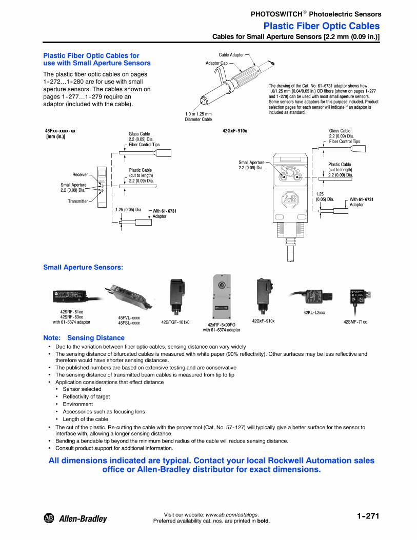
PHOTOSWITCHR Photoelectric Sensors
1--271Visit our website: www.ab.com/catalogs.Preferred availability cat. nos. are printed in bold.
Plastic Fiber Optic Cables foruse with Small Aperture Sensors
The plastic fiber optic cables on pages1--272…1--280 are for use with smallaperture sensors. The cables shown onpages 1--277…1--279 require anadaptor (included with the cable).
42GxF--910x45Fxx--xxxx--xx[mm (in.)] Glass Cable
2.2 (0.09) Dia.Fiber Control Tips
Plastic Cable(cut to length)2.2 (0.09) Dia.
Receiver
Small Aperture2.2 (0.09) Dia.
Transmitter
1.25 (0.05) Dia. With 61- 6731Adaptor
Small Aperture2.2 (0.09) Dia.
Glass Cable2.2 (0.09) Dia.Fiber Control Tips
Plastic Cable(cut to length)2.2 (0.09) Dia.
1.25(0.05) Dia. With 61- 6731
Adaptor
Small Aperture Sensors:
42SRF--61xx42SRF--63xx
with 61--6374 adaptor 42GTGF--101x0 42xRF--5x00FOwith 61--6374 adaptor
42GxF--910x
42KL--L2xxx
42SMF--71xx45FVL--xxxx45FSL--xxxx
Note: Sensing Distance• Due to the variation between fiber optic cables, sensing distance can vary widely• The sensing distance of bifurcated cables is measured with white paper (90% reflectivity). Other surfaces may be less reflective and
therefore would have shorter sensing distances.• The published numbers are based on extensive testing and are conservative• The sensing distance of transmitted beam cables is measured from tip to tip• Application considerations that effect distance
• Sensor selected• Reflectivity of target• Environment• Accessories such as focusing lens• Length of the cable
• The cut of the plastic. Re-cutting the cable with the proper tool (Cat. No. 57--127) will typically give a better surface for the sensor tointerface with, allowing a longer sensing distance.
• Bending a bendable tip beyond the minimum bend radius of the cable will reduce sensing distance.• Consult product support for additional information.
All dimensions indicated are typical. Contact your local Rockwell Automation salesoffice or Allen-Bradley distributor for exact dimensions.
Plastic Fiber Optic CablesCables for Small Aperture Sensors [2.2 mm (0.09 in.)]
1.0 or 1.25 mmDiameter Cable
Adaptor Cap
Cable Adaptor
The drawing of the Cat. No. 61--6731 adaptor shows how1.0/1.25 mm (0.04/0.05 in.) OD fibers (shown on pages 1--277and 1--279) can be used with most small aperture sensors.Some sensors have adaptors for this purpose included. Productselection pages for each sensor will indicate if an adaptor isincluded as standard.

PHOTOSWITCHR Photoelectric Sensors
1--272 Visit our website: www.ab.com/catalogs.Preferred availability cat. nos. are printed in bold.
The fiber optic cables on pages 1--272…1--279 are for use with small aperture sensors such as follows:
42GxF--910x
0 50 150100 200 250
Approximate Metric / Standard Distances
300120 2 64 8 1045FSL--xxxx 45FVL--xxxx
mm
in.42KL--L2xxx
Approximate Dimensions [mm (in.)]
BendRadius[mm (in.)]
Fiber CoreDiameter
SheathingMaterial Sensing Distance [mm] Cat. No.
23(0.91)
4.8(0.19) Dia.
1 (0.04)
15(0.59)
M6 x 1
40(1.6) 2 x 1.5 (0.06)
Polyethylene
43PR--NDS59FS
25 (1.0) 2 x 1 (0.04) 43PR--NDS57ZS
3.1(0.12)
4(0.16) Dia.
M6 x 0.75
17(0.67)
25 (1.0) 2 x 1 (0.04) Polyethylene 43PR--NES57ZS
4(0.16) Dia.
3.1(0.12)
250.0(10.0)
17(0.67)
M6 x 0.75
25 (1.0) 2 x 1 (0.04) Polyethylene 43PR--NES57VS
43PR--NKS61FS has coaxial optics for more precise sensing
2.5(0.1) Dia.
15(0.59)
3.1(0.12)
M6 x 0.75
25 (1.0) 2 x 1 (0.04)
Polyethylene
43PR--NKS57FS
20(0.8)
1 x 0.75(0.03)
4 x 0.5 (0.02)
Characterization not available attime of publication
43PR--NKS61FS
2(0.08) 2 x 0.5 (0.02) 1 R Polyflex Characterization not available at
time of publication43PR--NKS65YS
4.8(0.19) Dia.
23(0.9)
3.1 (0.12)M6, P=1 15
(0.59)2
(0.08) 2 x 1.0 (0.04) 1 R PolyflexCharacterization not available at time
of publication 43PR--NLS65YS
Note: Standard length for plastic fiber optic cables is 2 m (78 in.) tip to tip.
43PR Plastic Fiber Optic CablesThreaded Bifurcated Cables for Small Aperture Sensors [2.2 mm (0.09 in.)]

PHOTOSWITCHR Photoelectric Sensors
1--273Visit our website: www.ab.com/catalogs.Preferred availability cat. nos. are printed in bold.
Approximate Dimensions [mm (in.)]
BendRadius[mm (in.)]
FiberDiameter
SheathingMaterial Sensing Distance [mm] Cat. No.
M6 x 1
10R
23(0.91)
35(1.38)
15(0.59)
10(0.39)
10(0.39)
1.25(0.05) Dia.
Bend Here
15 (0.6) 2 x 0.5 (0.02) Polyethylene 43PR--PES53FS
M6 x 1
10R
23(0.91)
70(2.75)
15(0.59)
10(0.39)
10(0.39)
1.25(0.05) Dia.
Bend Here
15 (0.6) 2 x 0.5 (0.02) Polyethylene 43PR--PFS53FS
2.5(0.10) Dia.
Bendable ProbeM6 x 0.75
17(0.67)
90.0(3.5)
25 (1.0) 2 x 1 (0.04) Polyethylene 43PR--PIS57ZS
2.5(0.10) Dia
Bendable ProbeM6 x 0.75
90(3.5)
250(10)
17(0.67)
25 (1.0) 2 x 1 (0.04) Polyethylene 43PR--PIS57VS
1.27(0.05) Dia.
Bendable ProbeM3 x 0.51.0 (0.040) Dia x 2
90.0(3.5)
11.49(0.45)
15 (0.6) 2 x 0.5 (0.02) Polyethylene 43PR--PJS53ZS
1.27(0.05)Dia.
Bendable ProbeM3 x 0.5
1.0 (0.040) Dia x 2
90.0(3.5)
11.49(0.45)
15 (0.6) 2 x 0.5 (0.02) Polyethylene 43PR--PJS53VS
Note: Standard length for plastic fiber optic cables is 2 m (78 in.) tip to tip.
43PR Plastic Fiber Optic CablesThreaded Bifurcated Cables for Small Aperture Sensors [2.2 mm (0.09 in.)]

PHOTOSWITCHR Photoelectric Sensors
1--274 Visit our website: www.ab.com/catalogs.Preferred availability cat. nos. are printed in bold.
Approximate Dimensions [mm (in.)]Bend Radius[mm (in.)]
Fiber BundleDiameter
SheathingMaterial Sensing Distance Cat. No.
44.5(1.75)
Brazing Fillet
3.1 (0.12)
15.2(0.6)
14(0.55)
12.7 (0.5)max ref.
3.2(0.125)
5.08(0.2)
25 (1.0) 2 x 1 (0.04) PolyethyleneCharacterization not available at
time of publication 43PR--RAS57ZS
Specialty Cables for Small Aperture Sensors [2.2 mm (0.09 in.)]
11.9 (0.47)28.2 (1.11)
3.8 (0.15)
5.5 (0.22)dia. collar
2.0 (0.08)4.7 (0.187)
M5, P=0.81.6 (0.06) x 2.5 (0.1)oblong hole forside view
25 (1.0) 2 x 1 (0.04) PolyethyleneCharacterization not available at
time of publication 43PR--SBS57ZS
55.9 (2.2)
M6 x 0.75 thread
17 (0.67)
2.5(0.1)
2.5 (0.1)
Side ViewSensing
25 (1.0) 2 x 1 (0.04) PolyethyleneCharacterization not available at
time of publication 43PR--SCS57ZS
5.01(0.2)
23.8(0.94)11.9 (0.47)
23.9(0.94)
7.1 (0.28)
3.2 (0.125)Dia. 2 Places
OpticalAxis
6.0(0.235)
22.1(0.87)
30.0 (1.18)
2.0(0.08)
25 (1.0) 1 (0.04) Polyethylene
The sensing distance is thewidth of the gap (11.9 mm).The target must cross theoptical axis between the two
prongs of the fork
43PR--UAA56MS
Note: Standard length for plastic fiber optic cables is 2 m (78 in.) tip to tip.
43PR Plastic Fiber Optic CablesFerrule Bifurcated Cables for Small Aperture Sensors [2.2 mm (0.09 in.)]

PHOTOSWITCHR Photoelectric Sensors
1--275Visit our website: www.ab.com/catalogs.Preferred availability cat. nos. are printed in bold.
Approximate Dimensions [mm (in.)]
BendRadius[mm (in.)]
FiberBundleDiameter
SheathingMaterial Sensing Distance [mm] Cat. No.
M2.6 x 0.45M4 x 0.7
3.1 (0.12)11.0(0.43)
25 (1.0) 1 (0.04) Polyethylene 43PT--NJS56FS
M2.6 x 0.45M4 x 0.7
4 (0.16) Dia.
3.1 (0.12)250.0(10.0)
11.0(0.43)
25 (1.0) 1 (0.04) Polyethylene 43PT--NJS56GS
M4 x 0.7
15(0.59)
2.2(0.09) Dia.
3.1(0.12) Dia.
40 (1.6) 1.5 (0.06) Polyethylene 43PT--NAS58FS
2 (0.08) 1.0 (0.04) 1 R PolyflexCharacterization not available at time
of publication 43PT--NAS66RS
10(0.39)
10(0.39)
M4 x 0.7
15(0.59)
35(1.38)
0.87(0.034)Dia.
5(0.2)
1.0 (0.04)Dia.
Bend Here
10R
15 (0.6) 0.5 (0.02) Polyethylene 43PT--PAS52FS
69.9(2.75)
15.0(0.59)
2.54(0.1)
1.0(0.04)M4, P=0.7
0.76(0.03)
15 (0.6) 0.5 (0.02) Polyethylene 43PT--PBS52FS
Notes: Standard length for plastic fiber optic cables is 2 m (78 in.) tip to tip.Two cables per one plastic transmitted beam cat. no.
43PT Plastic Fiber Optic CablesThreaded Transmitted Beam Cables for Small Aperture Sensors [2.2 mm (0.09 in.)]

PHOTOSWITCHR Photoelectric Sensors
1--276 Visit our website: www.ab.com/catalogs.Preferred availability cat. nos. are printed in bold.
Approximate Dimensions [mm (in.)]
BendRadius[mm (in.)]
FiberBundle
DiameterSheathingMaterial Sensing Distance [mm] Cat. No.
1.27(0.05)Dia.
Bendable ProbeM6 x 0.75
90.0(3.5)
17(0.67)
25 (1.0) 1 (0.04) Polyethylene 43PT--PKS56FS
1.27(0.05)Dia.
Bendable ProbeM6 x 0.75
250.0(10.0)
90.0(3.5)
17(0.67)
25 (1.0) 1 (0.04) Polyethylene 43PT--PKS56GS
1.0 (0.04) Dia. M3 x 0.5
0.9(0.035)Dia.
Bendable Probe
11.0(0.43)
90.0(3.5)
15 (0.6) 0.5 (0.02) Polyethylene 43PT--PLS52FS
0.9(0.035)Dia.
M3 x 0.5Bendable Probe
250.0(10.0)
90.0(3.5)
11.0(0.43)
15 (0.6) 0.5 (0.02) Polyethylene 43PT--PLS52GS
Ferrule Transmitted Beam for Small Aperture Sensors [2.2 mm (0.09 in.)]
Approximate Dimensions [mm (in.)]
BendRadius[mm (in.)]
FiberBundle
DiameterSheathingMaterial Sensing Distance [mm] Cat. No.
15(0.59)
3.0(0.12) Dia.
2.2(0.09) Dia. 25 (1.0) 1 (0.04) Polyethylene 43PT--CBS56FS
M5 x 0.8
20(0.79)
5(0.19)
2.2(0.09) Dia.
4(0.16)Dia.
12(0.47)
2 (0.08)2.2
(0.09) Dia.
Side View Sensing
25 (1.0) 1 (0.04) PolyethyleneCharacterization not available at time
of publication 43PT--SAS56FS
Note: Standard length for plastic fiber optic cables is 2 m (78 in.) tip to tip.Two cables per one plastic transmitted beam Cat. No.
43PT Plastic Fiber Optic CablesThreaded Transmitted Beam Cables for Small Aperture Sensors [2.2 mm (0.09 in.)]

PHOTOSWITCHR Photoelectric Sensors
1--277Visit our website: www.ab.com/catalogs.Preferred availability cat. nos. are printed in bold.
Approximate Dimensions [mm (in.)]
BendRadius[mm (in.)]
FiberBundleDiameter
SheathingMaterial Sensing Distance [mm] Cat. No.
43PR--NAS60FM has coaxial optics for more precise sensing
15(0.59)
M4 x 0.7
3.1(0.12) Dia.
25 (1.0) 2 x 1 (0.04)
Polyethylene
43PR--NAS57ZM
15 (0.6)1 x 0.5 (0.02)4 x 0.25(0.01)
Characterization not available at timeof publication 43PR--NAS60FM
10(0.39)
M3, P=0.5
3.1(0.12) Dia.
2 (0.08)2 x 0.25(0.01) 1 R Polyflex
Characterization not available at timeof publication 43PR--NBS63YM
M4 x 0.7 15(0.59) 3.1
(0.12)
2.5(0.1) Dia.
15 (0.6) 2 x 0.5 (0.02) Polyethylene 43PR--NFS53FM
15 (0.59)
10.9(0.43)
70.0 (2.75)
2(0.08)
1.5(0.06)M3, P=0.5
1.3(0.05) 15 (0.6) 2 x 0.5 (0.02) Polyethylene 43PR--PHS53ZM
Ferrule Bifurcated Miniature Cables for Small Aperture Sensors (adaptor required) [2.2 mm (0.09 in.)]
Approximate Dimensions [mm (in.)]
BendRadius[mm (in.)]
FiberBundleDiameter
SheathingMaterial Sensing Distance [mm] Cat. No.5
15(0.59)
3.1 (0.12)Dia.
15 (0.6) 2 x 0.5 (0.02) Polyethylene 43PR--CBS53ZM
15(0.59)15
(0.59)
3.1 (0.12)Dia.
1.5(0.06) Dia.
1.25(0.05) Dia.
5(0.2)
15 (0.6) 2 x 0.5 (0.02) Polyethylene 43PR--AAS53ZM
Note: Standard length for plastic fiber optic cables is 2 m (78 in.) tip to tip.
43PR Plastic Fiber Optic CablesThreaded Bifurcated Miniature Cables for Small Aperture Sensors (adaptor required)

PHOTOSWITCHR Photoelectric Sensors
1--278 Visit our website: www.ab.com/catalogs.Preferred availability cat. nos. are printed in bold.
Approximate Dimensions [mm (in.)]
BendRadius[mm (in.)]
FiberBundleDiameter
SheathingMaterial Sensing Distance [mm] Cat. No.
15(0.59)
20(0.79)
3.1 (0.12)Dia.
0.8(0.03) 1
(0.04)
1.48(0.06) Dia.
0.9(0.03)
Side View Sensing
15 (0.6) 2 x 0.5 (0.02) PolyethyleneCharacterization not available at time
of publication 43PR--VBS53ZM
Note: Standard length for plastic fiber optic cables is 2 m (78 in.) tip to tip.
43PR Plastic Fiber Optic CablesFerrule Bifurcated Miniature Cables for Small Aperture Sensors (adaptor required)

PHOTOSWITCHR Photoelectric Sensors
1--279Visit our website: www.ab.com/catalogs.Preferred availability cat. nos. are printed in bold.
Approximate Dimensions [mm (in.)]
BendRadius[mm (in.)]
FiberBundleDiameter
SheathingMaterial Sensing Distance [mm] Cat. No.
M3 x 0.5 10(0.39)
1.25(0.05) Dia.
25 (1.0) 1 (0.04)
Polyethylene
43PT--NBS56FM
15 (0.6)
0.5 (0.02)
43PT--NBS52FM
2 (0.08) 1R PolyflexCharacterization not available at time
of publication 43PT--NBS64RM
M3 x 0.5 15(0.59)
15(0.59)1.25
(0.05) Dia.
0.87(0.03) Dia.
15 (0.6) 0.5 (0.02) Polyethylene 43PT--PCS52FM
Ferrule Transmitted Beam Miniature Cables for Small Aperture Sensors(adaptor required [2.2 mm (0.09 in.)])
Approximate Dimensions [mm (in.)]
BendRadius[mm (in.)]
FiberBundleDiameter
SheathingMaterial Sensing Distance [mm] Cat. No.
15(0.59)
20(0.79)
1.25(0.05) Dia.
1.0(0.04) Dia.
0.9(0.04)
0.8(0.03) Dia.
2(0.08)
Side View Sensing
15 (0.6) 0.5 (0.02) PolyethyleneCharacterization not available at time
of publication 43PT--VCS52FM
Note: Standard length for plastic fiber optic cables is 2 m (78 in.) tip to tip.Two cables per one plastic transmitted beam Cat. No.
43PT Plastic Fiber Optic CablesThreaded Transmitted Beam Miniature Cables for Small Aperture Sensors (adaptor required)

PHOTOSWITCHR Photoelectric Sensors
1--280 Visit our website: www.ab.com/catalogs.Preferred availability cat. nos. are printed in bold.
Approximate Dimensions [mm (in.)]Sensing Tip Material Fiber Diameter Sheathing Material Nominal Sensing Ref. Cat. No.
50.0 (1.97)
7.0(0.28)
200.0(7.87)
800.0(31.5)
6.35 (0.25)PTFE Tube Dia.1.25 (0.05)
Adaptor 61--6731required.
Do not bend fiber in this area.
PTFE 1.25 (0.049) x 2 PTFE NA 99--193--1
2000.0(78.74)
7.0(0.28)
6.35 (0.25)PTFE Tube Dia.
500.0(19.69)
1.25 (0.05)
Adaptor 61--6731required.
50.0 (1.97)
Do not bend fiber in this area.
PTFE 2.2 (0.090) x 2 PTFE NA 99--197--1
Plastic Fiber Optic CablesSpecial Purpose

PHOTOSWITCHR Photoelectric Sensors
1--281Visit our website: www.ab.com/catalogs.Preferred availability cat. nos. are printed in bold.
Custom Fiber Optic Cables
Rockwell Automation/Allen--Bradley can provide custom plastic fiber optic cables to meet nearly any applicationrequirement.
Typical cable modifications include:
S Custom lengths are available
S Custom temperature ratings up to 115_C (239_F)
S Custom configurations including multiple sensing tips
S Custom sensing end tips—nearly any modification is possible
For more information contact your local Rockwell Automation sales office or Allen-Bradley distributor.
To Build a Custom Fiber Optic
43 —
Fiber OpticCable
Fiber MaterialP = Plastic
Sensing ModeR = Reflective (Bifurcated)T = Transmitted Beam (Individual)
Sensing End TipS = Stainless SteelU = Plastic U Shape
Fiber BundlesSee pages 1--286 for dimensions.
SheathingF = Polyethylene 158_FG = Plastic CoiledZ = Zipped PlasticV = Zipped & CoiledR = PolyflexH = XPE (cross linked poly) 239_FY = Zipped Polyflex
Fits large aperture (0.187 in.OD) sensors which include:
42KL--L2xx42GxF--910x42GTGF--101x042SMF--71xx42SRF--61xx w/61--6374 adaptor*42SRF--63xx w/61--6374 adaptor*42Fx--Fxxxx42xRF--5x00FO
*Adaptors must be orderedseparately.
Overall Length (in.)Standard lengths are78 inches and do notrequire these spaces to befilled in. If shorter lengthsare required, the plasticfiber optic cable can becut to the desired lengthusing the cutting toolprovided in the packagewith the cable.
SP
Sensing End Tip StyleThreaded
Axial page 1--283Probe page 1--283Side view page 1--283U-Shaped page 1--284
FerruleAxial page 1--284Side view page 1--284Right angle page 1--284
Plastic Fiber Optic CablesAdditional Cables for Small Aperture Sensors [2.2 mm (0.09 in.) OD Sensor End Tip]

PHOTOSWITCHR Photoelectric Sensors
1--282 Visit our website: www.ab.com/catalogs.Preferred availability cat. nos. are printed in bold.
Custom Fiber Optic Cables
Rockwell Automation/Allen-Bradley can provide custom plastic fiber optic cables to meet nearly any applicationrequirement.
Typical cable modifications include:
S Custom lengths are available
S Custom temperature ratings up to 70_C (158_F)
S Custom configurations including multiple sensing tips
S Custom sensing end tips—nearly any modification is possible
For more information contact your local Rockwell Automation sales office or Allen-Bradley distributor.
To Build a Custom Fiber Optic
43 —
Fiber OpticCable
Fiber MaterialP = Plastic
Sensing ModeR = Reflective (Bifurcated)T = Transmitted Beam (Individual)
Sensing End Tip StyleThreaded
Axial page 1--283Probe 1--283Side view page 1--283 toU-Shaped page 1--284
FerruleAxial page 1--284Side view page 1--284Right angle page 1--284
Sensing End Tip and Nut MaterialS = Stainless Steel
Fiber BundlesSee page 1--286 for dimensions.
SheathingF = Polyethylene 158_FG = Plastic CoiledZ = Zipped PlasticV = Zipped & CoiledR = PolyflexY = Zipped Polyflex
Fits small aperture sensorswith adaptor included with thefiber optic cable:
42KL--L2xxx w/61--6731 adaptor*42GxF--910x w/61--6731 adaptor*42GTGF--101x0 w/61--6731 adaptor*45FVL--xxxx--xx w/supplied adaptors45FSL--xxxx--xx w/supplied adaptors
*Adaptors must be ordered separately.
Overall Length (in.)Standard lengths are 78inches and do not requirethese spaces to be filledin. If shorter lengths arerequired, the plastic fiberoptic cable can be cut tothe desired length usingthe cutting tool provided inthe package with thecable.
M
Plastic Fiber Optic CablesAdditional Cables for Small Aperture Sensors [1.0/1.25 mm (0.04/0.05 in.) OD Sensor End Tip]

PHOTOSWITCHR Photoelectric Sensors
1--283Visit our website: www.ab.com/catalogs.Preferred availability cat. nos. are printed in bold.
Approximate Dimensions Code
StandardBundle[mm]
Approximate Dimensions [mm (in.)]
A B C D E F
F E
A
B
C
D
NA 0.5 14.9 (0.59) — M4, P=0.7 0.51 (0.02) 3.0 (0.12) —
NB 0.5 9.9 (0.39) — M3, P=0.5 NA — —
NC 0.25 11.9 (0.47) — M4, P=0.7 3.05 (0.12) 1.02 (0.04) —
ND 1.5 13.9 (0.55) 23.1 (0.91) M6, P=1 1.02 (0.04) 4.8 (0.19) —
NE 1.0 17.0 (0.67) — M6, P=0.75 3.05 (0.12) 4.06 (0.16) —
NF 0.5 11.9 (0.47) — M4, P=0.7 3.05 (0.12) 2.54 (0.10) —
NG 0.75 10.9 (0.43) 14.9 (0.59) M3, P=0.5 NA — 3.05 (0.12)
NJ 1.0 11.9 (0.47) — M4, P=0.7 3.05 (0.12) — —
NK 0.5 11.9 (0.47) — M6, P=0.75 3.05 (0.12) 2.54 (0.10) —
NL 0.5 14.9 (0.59) 23.1 (0.91) M6, P=1 4.8 (0.19) 6.1 (0.24) 6.1 (0.24)
Approximate Dimensions Code
StandardBundle[mm]
Approximate Dimensions [mm (in.)]
A B C D E F G
A BG
F C D E
PA 0.5 14.9 (0.59) 35.0 (1.38) 2.54 (0.1) 1.02 (0.04) 0.76 (0.03) M4, P=0.7 —
PB 0.5 14.9 (0.59) 69.8 (2.75) 2.54 (0.1) 1.02 (0.04) 0.76 (0.03) M4, P=0.7 —
PD 0.5 9.9 (0.39) 69.8 (2.75) 2.03 (0.08) 1.02 (0.04) 0.76 (0.03) M3, P=0.5 —
PE 0.5 14.9 (0.59) 35.0 (1.38) 2.54 (0.1) 1.52 (0.06) 1.27 (0.05) M6, P=1 23.1 (0.91)
PF 0.5 14.9 (0.59) 69.8 (2.75) 2.54 (0.1) 1.52 (0.06) 1.27 (0.05) M6, P=1 23.1 (0.91)
PG 0.5 14.9 (0.59) 69.8 (2.75) 2.54 (0.1) 1.52 (0.06) 1.27 (0.05) M4, P=0.7 —
PH 0.5 10.9 (0.43) 69.8 (2.75) 2.03 (0.08) 1.52 (0.06) 1.27 (0.05) M3, P=0.5 14.9 (0.59)
Approximate Dimensions Code
StandardBundle[mm]
Approximate Dimensions [mm (in.)]
A B C D
A B
D
C
PC 0.5 14.9 (0.59) 14.9 (0.59) 0.76 (0.03) M3, P=0.5
PI 1.0 17.0 (0.67) 88.9 (3.5) 2.54 (0.1) M6, P=0.75
PJ 0.5 11.4 (0.45) 88.9 (3.5) 1.27 (0.05) M3, P=0.5
PK 1.0 17.0 (0.67) 88.9 (3.5) 1.27 (0.05) M6, P=0.75
PL 0.5 10.9 (0.43) 88.9 (3.5) 0.86 (0.034) M3, P=0.5
Approximate Dimensions [mm (in.)] Code Standard Bundle [mm]
11.9(0.47)
M5, P=0.8
20.1 (0.79)
4.8 (0.19)2.0 (0.08)
4.06 (0.16)Dia.
2.2 (0.09) Dia.
Side ViewSensing
SA 1.0
Plastic Fiber Optic Cable Sensing TipsUse with Configurators on page 1--281 and 1--282.

PHOTOSWITCHR Photoelectric Sensors
1--284 Visit our website: www.ab.com/catalogs.Preferred availability cat. nos. are printed in bold.
Approximate Dimensions [mm (in.)] Code Standard Bundle [mm]
14.9(0.59)
0.81(0.032)
2.49(0.098)1.52
(0.06)
2.29(0.09)
14.9(0.59)
Side ViewSensing
VC 0.5
Approximate Dimensions [mm (in.)] Code Standard Bundle [mm]
28.1(1.11)
11.9(0.47)
4.7(0.18) (2.03
(0.08)3.81(0.15)
5.54 (0.21)dia. collar
M5, P=0.81.63 (0.064) x2.5 (0.098)1mm pair
Side ViewSensing
SB 1.0
Approximate Dimensions [mm (in.)] Code Standard Bundle [mm]
17.0(0.67)
55.8(2.2)
3.0(0.12)
2.54(0.1)
2.54(0.1)M6 x 0.75
thread
Side ViewSensing
SC 1.0
Approximate Dimensions [mm (in.)] Code Standard Bundle [mm]
13.97(0.55)
12.7(0.5)
15.24 (0.6)
3.05 (0.12)
44.45(1.75)
3.18 (0.125)
5.08(0.2)
RA 1.0
Plastic Fiber Optic Cable Sensing TipsUse with Configurators on page 1--281 and 1--282.
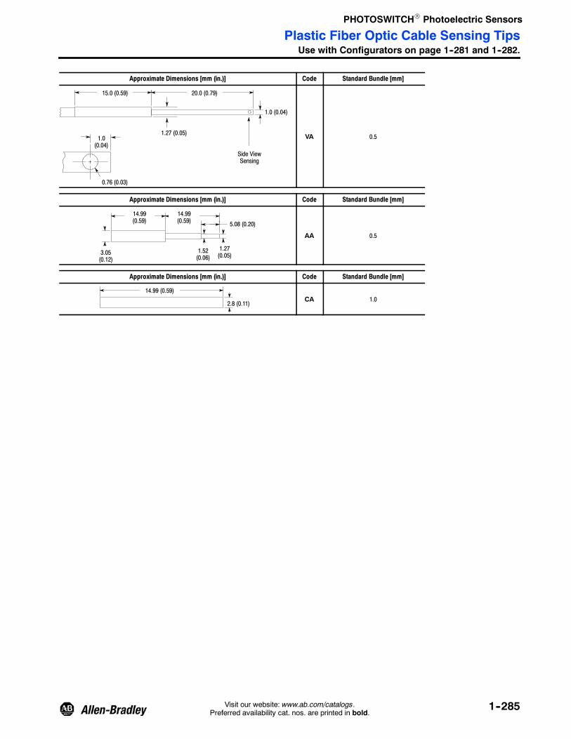
PHOTOSWITCHR Photoelectric Sensors
1--285Visit our website: www.ab.com/catalogs.Preferred availability cat. nos. are printed in bold.
Approximate Dimensions [mm (in.)] Code Standard Bundle [mm]
1.27 (0.05)
15.0 (0.59) 20.0 (0.79)
0.76 (0.03)
1.0 (0.04)
1.0(0.04)
Side ViewSensing
VA 0.5
Approximate Dimensions [mm (in.)] Code Standard Bundle [mm]
3.05(0.12)
14.99(0.59)
14.99(0.59)
1.52(0.06)
1.27(0.05)
5.08 (0.20)
AA 0.5
Approximate Dimensions [mm (in.)] Code Standard Bundle [mm]
14.99 (0.59)
2.8 (0.11)CA 1.0
Plastic Fiber Optic Cable Sensing TipsUse with Configurators on page 1--281 and 1--282.

PHOTOSWITCHR Photoelectric Sensors
1--286 Visit our website: www.ab.com/catalogs.Preferred availability cat. nos. are printed in bold.
The bundle size codes are used with the configurators on page 1--281 and 1--282.
Code Diameter [mm] Bend Radius [mm (in.)] Arrangement
52 0.50 15 (0.6) Single
53 0.50 15 (0.6) Pair Zipped
56 1.0 25 (1.0) Single
57 1.0 25 (1.0) Pair Zipped
58 1.5 40 (1.6) Single
59 1.5 40 (1.6) Pair
60 0.50 x 10.25 x 4 15 (0.6) Coaxial
61 0.75 x 10.50 x 4 20 (0.8) Coaxial
64 0.50 2 (0.08) Single Flexible
65 0.50 2 (0.08) Pair Flexible
66 1.0 2 (0.08) Single Flexible
67 1.0 2 (0.08) Pair Flexible
Plastic Fiber Optic Cable Sensing TipsUse with Configurators on page 1--281 and 1--282.

PHOTOSWITCHR Photoelectric Sensors
1--287Visit our website: www.ab.com/catalogs.Preferred availability cat. nos. are printed in bold.
Description Approximate Dimensions [mm (in.)] Cat. No.
Cutting Tool for plastic Fiber Optic cable. For use with all cutablecables. One cutter tool is packaged with each fiber optic cable.
44.45(1.75)
19.05(0.75)
57-127
Molded Fiber Optic Adaptor Kit to be used with Type 42DRF andType 42MRF Series 5000.
61-6310
Control End Adaptor Kit for 2.3 mm (0.09 in.) OD Plastic Fiber Opticcable. Use with Series 9000, 10,000, 5000 and 6000.
7.2(0.28) Dia.
4.3(0.17) Dia.
19.7(0.78)
9.5(0.38) Dia.
7(0.28)
34(1.34)
61-6374
2/package
Control End Adaptor Kit for Series 7000.129- 125- 5
2/package
1.25 mm outer jacket adaptor for the 42FA and 42FT (included withsensor) and MiniSight, Series 9100 and 10,000 (adaptor notincluded)
1.25 mm Diameter Cable
Adaptor Cap
Cable Adaptor
61- 6731
1.0 mm outer jacket adaptor for 45FVL/45FSL 61- 6742
2.2 mm outer jacket adaptor for the 42FB (included with sensor) CableAdaptors
Locking Cap(supplied withn sensor)Plastic Fibre
Optic Cables
61- 6733
Plastic Fiber Optic CablesAccessories

PHOTOSWITCHR Photoelectric Sensors
1--288 Visit our website: www.ab.com/catalogs.Preferred availability cat. nos. are printed in bold.
Lenses (One per package)Description Approximate Dimensions [mm (in.)] Cat. No.
Range extender lens adaptor for 1 mm (0.04 in.) dia.transmitted beam plastic cable.
2.8 (0.11) Dia.Glass Lens3.8
(0.16) Dia.
9.3(0.37)
M2.6 x 0.45Internal Thread
63-118
Fixed focus lens adaptor used with reflective cableswith 4 mm (0.16 in.) x 0.7 pitch threaded sensing tips.
Plastic housing
One Cat. No. = one adaptor
15(0.59)
6(0.24)
4(0.16)
6(0.24)
60- 2646
Right angle lens adaptor used with transmitted beamcables with 4 mm (0.16 in.) x 0.7 pitch threaded
sensing tips.
Metal housing
One Cat. No. = one adaptor
15(0.59)
9.5(0.37)
5.5 (0.22)
3 (0.12)
5 (0.2)
2.3 (0.92)Side View Sensing
60- 2648
Range extender lens adaptor used with transmittedbeam cables with 4 mm (0.16 in.) x 0.7 pitch threaded
sensing tips.
Metal housing
One Cat. No. = one adaptor6.7 (0.26) 6.7 (0.26)
0.3 (0.01)
10(0.39)
60- 2652
Plastic Fiber Optic CablesAccessories

PHOTOSWITCHR Photoelectric Sensors
1--289Visit our website: www.ab.com/catalogs.Preferred availability cat. nos. are printed in bold.
General Specifications
Housing Material Nickel-plated brass
Operating Temperature [C (F)] --25…+60_ (--13…+140_)
Acceptable Fiber 2.2 mm (0.08 in.) outer diameter
Fiber Optic Cable Bifurcated = 99--854Individual = 99--850
Approximate Dimensions [mm (in.)]
Description Approximate Dimensions [mm (in.)]Nominal Sensing Distance
[mm (in.)] Cat. No.
Range extendinglens for ColorSight
9000 22.35(0.88)
50.8 (2.0)
5/16--24 Thread
114 (4.5) 60--2738
Lens for diffusesensing. Accepts2.2 mm plasticbifurcated fiberoptic cable.
One Cat. No. = onelens assembly
28 (1.10)
Optic
5.5 (0.21) Dia.M8L = 10
8 (0.31) Dia.
70 (2.75) 60--2745
Range extendinglens for transmittedbeam sensing.Accepts 2.2 mmplastic individualfiber optic cable.
One Cat. No. = twolens assemblies
9(0.35)
16 (0.62)
3 (0.11) Dia.5 (0.19) Dia.
200 (7.87) 60--2746
Range extendinglens for transmittedbeam sensing.Accepts 2.2 mmplastic individualfiber optic cable.
One Cat. No. = twolens assemblies
16 (0.62)
3 (0.11) Dia.
9(0.35)
5 (0.19) Dia.
Optic
800 (31.49) 60--2747
Range extendinglens for transmittedbeam sensing.Accepts 2.2 mmplastic individualfiber optic cable.
One Cat. No. = twolens assemblies
25 (0.98)Optic
M6L = 106 (0.23) Dia.
1200 (47.24) 60--2748
Plastic Fiber Optic CablesFiber Optic Lens Assemblies (Field Attachable)
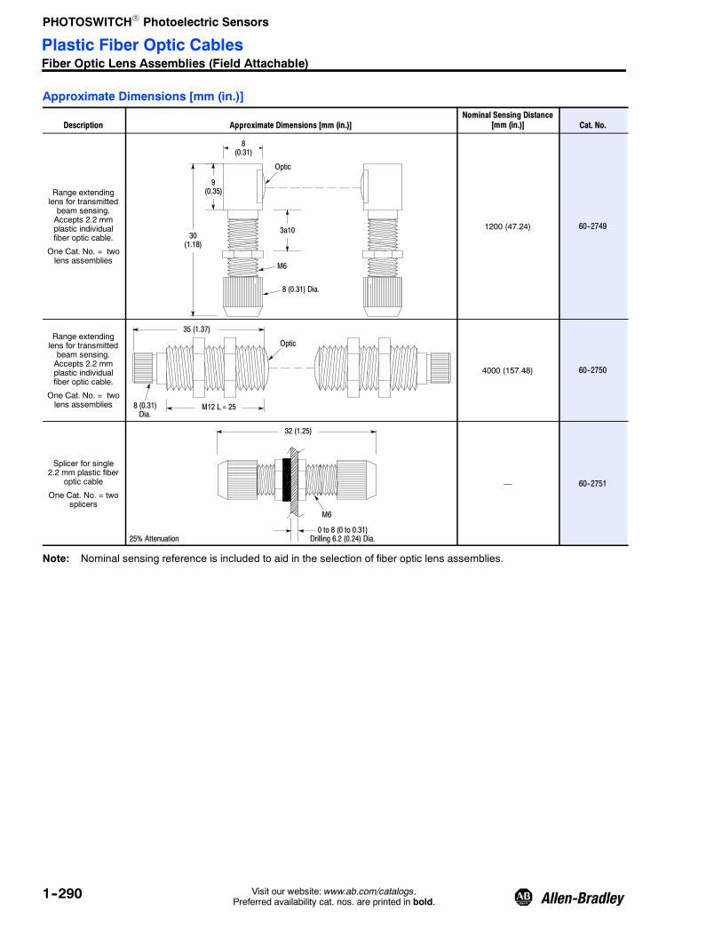
PHOTOSWITCHR Photoelectric Sensors
1--290 Visit our website: www.ab.com/catalogs.Preferred availability cat. nos. are printed in bold.
Approximate Dimensions [mm (in.)]
Description Approximate Dimensions [mm (in.)]Nominal Sensing Distance
[mm (in.)] Cat. No.
Range extendinglens for transmittedbeam sensing.Accepts 2.2 mmplastic individualfiber optic cable.
One Cat. No. = twolens assemblies
9(0.35)
Optic
8 (0.31) Dia.
30(1.18)
3a10
8(0.31)
M6
1200 (47.24) 60--2749
Range extendinglens for transmittedbeam sensing.Accepts 2.2 mmplastic individualfiber optic cable.
One Cat. No. = twolens assemblies
35 (1.37)
Optic
M12 L = 258 (0.31)Dia.
4000 (157.48) 60--2750
Splicer for single2.2 mm plastic fiber
optic cable
One Cat. No. = twosplicers
32 (1.25)
0 to 8 (0 to 0.31)Drilling 6.2 (0.24) Dia.
M6
25% Attenuation
— 60--2751
Note: Nominal sensing reference is included to aid in the selection of fiber optic lens assemblies.
Plastic Fiber Optic CablesFiber Optic Lens Assemblies (Field Attachable)

PHOTOSWITCHR Photoelectric Sensors
1--291Visit our website: www.ab.com/catalogs.Preferred availability cat. nos. are printed in bold.
Unterminated Plastic Fiber Optic CablesDescription Approximate Dimensions [mm (in.)] Cat. No.
Simplex
2.2 (0.09)
30 m(98.5 ft)
1.0 (0.04)
Single Fiber
Optical Fiber
Jacket (PE) 99- 850
Duplex
1.0(0.04) 2.2(0.09)
4.4(0.18)
Zipped
Optical Fiber
Jacket (PE)
30 m(98.5 ft)
99- 854
Simplex
1.0 (0.04) Jacket (PE)30 m(98.5 ft)
0.5 (0.02) Single Fiber
Optical Fiber99- 852
Duplex30 m(98.5 ft)
0.5 (0.02)Zipped
Optical Fiber
Jacket (PE)1.0 (0.04)
2.0 (0.08) 99- 853
The above cat. nos. are unterminated simplex (individual) and duplex (dual) plastic fibers.
These plastic fiber optic cables can be used with plastic fiber optic sensors and require no control end tip to interface to thesensor.
A cutting tool for these unterminated plastic fiber optic cables is packaged with the fiber cable.
Plastic Fiber Optic CablesAccessories

PHOTOSWITCHR Photoelectric Sensors
1--292 Visit our website: www.ab.com/catalogs.Preferred availability cat. nos. are printed in bold.
Cat. No. Cat. No.
99--1000--1 43GR--TAS20ML
99--1003--1 43GR--XDB25SL
99--108 43PT--PLS52FS
99--109 43PT--PLS52GS
99--110 43PR--PJS53ZS
99--116--1 43GT--MIS15SL
99--161--1 43GR--TAB20SS
99--181--1 43GT--TWC25SL
99--184--1 43GT--2FAS20SL
99--201--1 43GR--FOS20ML
99--206--1 43GR--FPS20SL
99--214--1 43GR--FJS30SL
99--222--1 43GR--TMC25SL
99--224--1 43GR--TMC15SL
99--238--1 43GR--FGS25SL
99--275--1 43GR--TFS10ML
99--279--1 43GR--MUS10ML
99--283--1 43GR--MSC10ML
99--290--1 43GR--MHS15SL
99--291--1 43GR--MHS15ML
99--294--1 43GR--BCA73SL
99--300--1 43GR--TBS25SL
99--30--1 43GR--FAS25SL
99--301--1 43GR--TBS25ML
99--302--1 43GR--TBB30SL
99--304--1 43GR--TQC25SL
99--308--1 43GR--TRC30SL
99--31--1 43GR--FAS25ML
99--315--1 43GR--TKC25ML
99--32--1 43GR--TBB25SL
99--330--1 43GR--TTS20SL
99--33--1 43GR--TBB25ML
99--34--1 43GR--FIS25SL
99--350--1 43GR--FRS40SL
99--35--1 43GR--FIS25ML
99--36--1 43GR--BAA72SL
99--37--1 43GR--BAA72ML
99--39--1 43GR--MKS00ML
99--400--1 43GT--FOS20SL
99--408--1 43GT--FPS10SL
99--424--1 43GT--TMC15SL
99--426--1 43GT--TOC30SL
99--436--1 43GT--FAS30SL
99--453--1 43GT--TJC30ML
99--458--1 43GT--MBS10SL
99--46--1 43GR--TXC25SL
Cat. No. Cat. No.
99--461--1 43GT--MMS10ML
99--477--1 43GT--TFS00ML
99--479--1 43GT--MUS10ML
99--487--1 43GT--MRS10ML
99--490--1 43GT--MHS15SL
99--491--1 43GT--MHS15ML
99--494--1 43GT--BCA73SL
99--495--1 43GT--BCA73ML
99--500--1 43GT--TBS25SL
99--50--1 43GT--FAS25SL
99--501--1 43GT--TBS25ML
99--502--1 43GT--TBB30SL
99--504--1 43GT--TQC25SL
99--505--1 43GT--TQC25ML
99--508--1 43GT--TRC30SL
99--51--1 43GT--FAS25ML
99--52--1 43GT--TBB25SL
99--530--1 43GT--TTC20SL
99--53--1 43GT--TBB25ML
99--54--1 43GT--FIS25SL
99--55--1 43GT--FIS25ML
99--56--1 43GT--BAA72SL
99--57--1 43GT--BAA72ML
99--58--1 43GT--MKS00SL
99--59--1 43GT--MKS00ML
99--614--1 43GR--MQS15SL
99--623--1 43GR--2FAS25SL
99--626--1 43GT--6TBB15SL
99--643--1 43GR--4TBB22SL
99--68--1 43GR--MVS00ML
99--69--1 43GT--TMC25SL
99--700--1 43GR--TBS20MS
99--701--1 43GR--TBS15ML
99--702--1 43GR--TAS20MS
99--704--1 43GR--TAS20SS
99--705--1 43GR--TMS25ML
99--706--1 43GR--TMS20MS
99--708--1 43GR--TQS20MS
99--710--1 43GT--TBS15MS
99--714--1 43GT--TAS15SS
99--714--1 43GT--TAS15SS
99--715--1 43GT--TFS10ML
99--716--1 43GT--TOS30ML
99--717--1 43GT--TQS25ML
99--718--1 43GT--TQS15MS
99--720--1 43GT--TRS30ML
Cat. No. Cat. No.
99--721--1 43GT--MIS15ML
99--722--1 43GT--TMS25ML
99--723--1 43GT--TMS15MS
99--751--1 43GR--XAS10SS
99--752--1 43GR--TIS10SS
99--753--1 43GR--FTS10SS
99--755--1 43GR--TDS10SS
99--794--1 43GR--BRA79SL
99--800 43PR--NDS59FS
99--801 43PR--NDS57ZS
99--802 43PR--NAS57ZM
99--803 43PR--NAS60FM
99--804 43PR--NKS57ZS
99--805 43PR--NKS61FS
99--806 43PR--NFS53FM
99--808Z 43PR--NGS53ZM
99--809Z 43PR--NGS55ZM
99--810 43PR--PES53FS
99--811 43PR--PFS53FS
99--814 43PR--CBS53ZM
99--816 43PR--AAS53ZM
99--818 43PR--VBS53ZM
99--819 43PT--NAS58FS
99--820 43PT--NBS56FM
99--821 43PT--NBS54FM
99--822 43PT--NBS52FM
99--823 43PT--PAS52FS
99--825 43PT--PCS52FM
99--827 43PT--CBS56FS
99--828 43PT--SAS56FS
99--833 43PR--SCS57ZS
99--838 43PR--SBS57ZS
99--85--1 43GR--TGB33SL
99--90 43PT--NJS56FS
99--900 43PR--RAS57ZS
99--91 43PT--NJS56GS
99--92 43PT--PKS56FS
99--93 43PT--PKS56GS
99--94 43PR--NES57ZS
99--95 43PR--NES57VS
99--951--1 43GT--XAS10SS
99--952--1 43GT--TIS10SS
99--953--1 43GT--FTS10SS
99--955--1 43GT--TDS10SS
99--96 43PR--PIS57ZS
99--97 43PR--PIS57VS
Fiber Optic Cable Cross Reference

PHOTOSWITCHR Photoelectric Sensors
AccessoriesMounting Brackets/Adaptor
1--293Visit our website: www.ab.com/catalogs.Preferred availability cat. nos. are printed in bold.
Description Cat. No. Used for Approximate Dimensions [mm (in.)]
Swivel/Tilt bracketallows10_ verticaland 360_ rotationadjustment.
60- 2649 RightSight
28.6(1.13)
7.95(0.31)50.08
(2.0)
57.15(2.25)
10_ Adjustment ineach direction
28.6(1.13)
7.95(0.31)50.08
(2.0)
87.0(3.42)
10_ Adjustment ineach direction
60- 2439Series 9000Color SightLaserSight
60- 2681 ClearSight 9000
60- 2619 Series 7000
60- 2618 Series 6000
Right angle mountingbracket allows 30_horizontal adjustment.
60- 2664 MiniSight42CA, 42CB
18 (0.70)Dia. 38.1
(1.50)
31.8(1.25)
45.5(1.79)
60- 2657RightSightMiniSight42CA, 42CB
)
35.8(1.41)
42.4(1.67)35.8
(1.41)
18 (0.70)Dia.
Right angle mountingbracket permits a360_ rotationadjustment. The Cat.No. 60--2513 brackethas mounting holepatterns compatiblewith the Cat. No.60--1785.
60- 242160- 2513
Series 9000ClearSight 9000ColorSightLaserSight
71.1(2.8)
60.2(2.37)
67.3(2.65)
71.1(2.8)
119.4(4.70)
67.3(2.65)

PHOTOSWITCHR Photoelectric Sensors
AccessoriesMounting Brackets
1--294 Visit our website: www.ab.com/catalogs.Preferred availability cat. nos. are printed in bold.
Description Cat. No. Used for Approximate Dimensions [mm (in.)]
Right angle mountingbracket allows 40_horizontal rotation.The Cat. No.60--2152 permits a30_ horizontalrotation.
60- 215160- 2152 Series 7000 53.85
(2.12)
12.95(0.51)
24.64(0.97)
Right angle mountingbracket with 25.4 mm(1 in.) knockout forSeries 6000 sensor.
60- 2006 Series 6000
63.5(2.5)
49.3(1.94)
35.8(1.41)
Tilt mounting bracketprovides 30_ verticalheight adjustment.
60- 2007 Series 6000
66.8(2.63)
13.97(0.55)
31.75(1.25)
Right angle mountingbracket allows forboth horizontal andvertical adjustment.
60- 2008 Series 6000
84.1(3.31)
41.2(1.66)
34.9(1.36)
Right angle mountingbracket providesvertical height and360_ rotation.
60- 1785 Series 5000
73.4(2.89)
67.56(2.66)
42.9(1.69)

PHOTOSWITCHR Photoelectric Sensors
AccessoriesMounting Brackets/Adaptor
1--295Visit our website: www.ab.com/catalogs.Preferred availability cat. nos. are printed in bold.
Description Cat. No. Used for Approximate Dimensions [mm (in.)]
Right angle mountingbracket intended foruse with Unistruttchannel providesmany vertical andhorizontaladjustments.
60- 2014 Series 5000
76.2(3.0)
67.3(2.65)
120.6(4.75)
Right angle mountingbracket allows 360_rotation and has holepatterns to matchstandard NEMA stylelimit switches.
60- 2230 Series 5000
67.0(2.65)
102(4.0)
71.0(2.8)
Right angle mountingbracket provides360_ rotation.
60- 1479 Series 4000
79.4(3.13)
42.9(1.69)
90.5(3.56)
Straight mountingbracket provides 30_horizontal rotation.
60- 2656RightSightMiniSight42CA, 42CB
70.0(2.75)
42.0(1.65)
Side mountingbracket provides 30_of vertical and 20_ ofhorizontal rotation.
60- 2663 MiniSight20.1(0.79)
31.75(1.25)
40.39(1.59)
Photoelectric sensorvertical heightadjustment bracketslotted for any swivel/tilt bracket.
60- 2721 (2 x 4 in.)60- 2722 (2 x 6 in.)60- 2723 (2 x 8 in.)60- 2724 (2 x 10 in.)
RightSightMiniSightSeries 9000ClearSight 9000ColorSightLaserSight
101.6(4.0)
50.8(2.0)
152.4(6.0)
H

PHOTOSWITCHR Photoelectric Sensors
AccessoriesMounting Brackets
1--296 Visit our website: www.ab.com/catalogs.Preferred availability cat. nos. are printed in bold.
Description Cat. No. Used for Approximate Dimensions [mm (in.)]
Stainless steelmounting bracket 60- BKTL- SS 44B
42JS VisiSight
29.97(1.18)
46.48(1.83)
Mounting bracket 60- 2677 45MLD
45.0 (1.77)
100.0(3.94)
76.0 (2.99)
Clamp style bracketfits any 18 mmsensor.
871A- BP18RightSightMiniSight42CA, 42CB
29.4(1.16)
13(0.512)
45(1.77)
32(1.26)
Flush mount adaptorallows any 18 mmsensor to be mountedflush against panelsurface.
60- 2590RightSightMiniSight42CA, 42CB
Heavy duty impactbracket of #12 steelcan be used withswivel/tilt bracket.
60- 2695
A = 76 mm (3 in.)
RightSightMiniSightSeries 9000ColorSightLaserSight
19(0.75)
140(5.5)
45(1.8)
121.9 (4.8)
100(3.9)A
60- 2702
A = 117 mm (4.6 in.)ClearSight 9000
Heavy duty impactbracket of #12 steelcan be used withswivel/tilt bracket.
60- 2725 Series 9000
63.5(2.5)
75(2.9)

PHOTOSWITCHR Photoelectric Sensors
AccessoriesMounting Brackets/Adaptor
1--297Visit our website: www.ab.com/catalogs.Preferred availability cat. nos. are printed in bold.
Description Cat. No. Used for Approximate Dimensions [mm (in.)]
Heavy duty mountingbracket designed foruse in high vibrationapplications providesboth horizontal andvertical heightadjustment.
60- 1748 Series 5000
Heavy duty impactbracket of #12 steelcan be used with theCat. No. 60--1785mounting bracket.
60- 2083 Series 5000
79.4(3.13)
196.8(7.75)
130.2(5.13)
Heavy duty impactbracket protectssensor and provides60_ horizontaladjustment.
60- 1665 Series 4000
Mounting bracket(included with sensor) 60- 2773 45PVA
20(0.78)
20(0.78)
4.6(0.18) Dia.
4.6(0.18) Dia.
10(0.39)
10(0.39)
59 (2.32)
16 (062) 18 (0.7)
2 (0.07)
Plastic bracket(2 brackets) 60- 2779 45PVA 26.9
(1.06) Dia. 66(2.60)
4.4 (0.17)
20.1(0.79)
18.8 (0.74)
7.4 (0.29)
18.0(0.71)
7.6 (0.30)17.0 (0.67)
34.0 (1.34)

PHOTOSWITCHR Photoelectric Sensors
AccessoriesMounting Brackets
1--298 Visit our website: www.ab.com/catalogs.Preferred availability cat. nos. are printed in bold.
Description Cat. No. Used for Approximate Dimensions [mm (in.)]
Metal brackets(2 brackets) 60- 2772 45PVA
51.8 (2.04)
2 x M5 x 0.8
16.0(0.63)
18.0(0.71)
7.4 (0.29)18.0 (0.71)
9.2 (0.36)
7.0 (0.27)
68.3 (2.69)
28.0 (1.10)Dia. 2.5
(0.10)
5.2 (0.20) Dia.
2 x 16.0 (0.63)
28.0 (1.10)
4 x M4 x 0.732.0(1.26)
Galvanized steel 60- 2775- 1 45PVA -- 1LEB1--F4
L1
4 x R 5.08(0.20)
7.01(0.27)
16.3 (0.64)
17.5(0.689)
R 3.05(0.12)
12.34(0.486)
8.99(0.354) Ref.
2 x 18 (0.709)
2 x R 2.03(0.08)
4 x 4.97(0.196) Dia.
10.0(0.39)
111.3 (4.38)68.3 (2.69)51.3 (2.02)
27.3 (1.07)
L2
Galvanized steel 60- 2776- 1 45PVA -- 1LEB2--F4
Galvanized steel 60- 2777- 1 45PVA -- 1LEB3--F4
Galvanized steel 60- 2778- 1 45PVA -- 1LEB4--F4L1
4 x R 5.08(0.20)
7.01(0.27)
16.3 (0.64)
17.5(0.689)
R 3.05(0.12)
12.34(0.486)
8.99(0.354) Ref.
2 x 18 (0.709)
2 x R 2.03(0.08)
4 x 4.97(0.196) Dia.
10.0(0.39)
111.3 (4.38)68.3 (2.69)51.3 (2.02)
27.3 (1.07)
L2
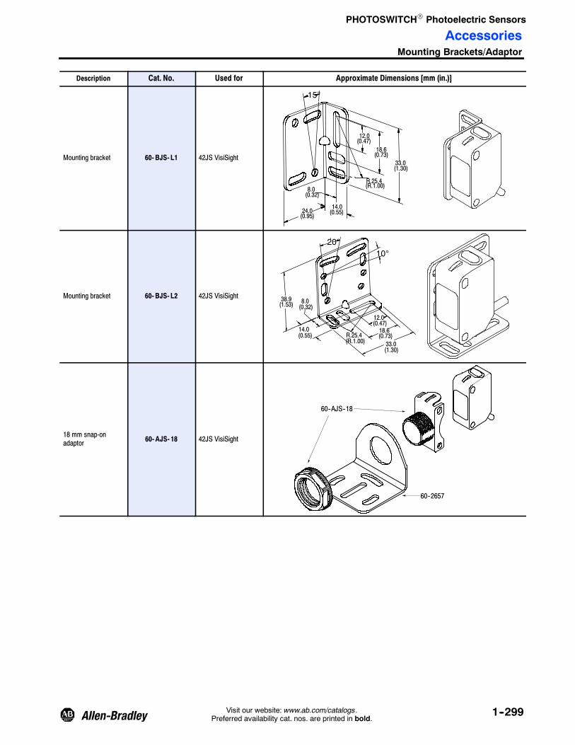
PHOTOSWITCHR Photoelectric Sensors
AccessoriesMounting Brackets/Adaptor
1--299Visit our website: www.ab.com/catalogs.Preferred availability cat. nos. are printed in bold.
Description Cat. No. Used for Approximate Dimensions [mm (in.)]
Mounting bracket 60- BJS- L1 42JS VisiSight
12.0(0.47)
18.6(0.73)
33.0(1.30)
14.0(0.55)24.0
(0.95)
8.0(0.32)
15°
R.25.4(R.1.00)
Mounting bracket 60- BJS- L2 42JS VisiSight
12.0(0.47)
33.0(1.30)
14.0(0.55)
38.9(1.53)
18.6(0.73)
8.0(0.32)
R.25.4(R.1.00)
20°10°
18 mm snap-onadaptor 60- AJS- 18 42JS VisiSight
60--AJS--18
60--2657

PHOTOSWITCHR Photoelectric Sensors
AccessoriesProtective Brackets and Apertures
1--300 Visit our website: www.ab.com/catalogs.Preferred availability cat. nos. are printed in bold.
Description Cat. No. Used for Approximate Dimensions [mm (in.)]
Dovetail mountingbracket 44B- BKT 44B
45LSP
18 mm mounting kitcontains lockwasher,nuts, and screws forboth body or thru-holemounting.
60- 2716 RightSight
18 mm mounting nut,plastic (2 each). 871T- N3
RightSightMiniSight42CA, 42CB
18 mm mounting nut,stainless steel(2 each).
871T- N4RightSightMiniSight42CA, 42CB
18 mm lockwasher,metal 871A- LWN18
RightSightMiniSight42CA, 42CB
30 mm mounting kitcontains lockwasher,nuts, and screws forboth body or thru-holemounting.
129- 130
Series 9000ColorSightLaserSightClearSight 9000
Replacement userinterface cover. 60- 2620
Series 9000ColorSightLaserSightClearSight 9000
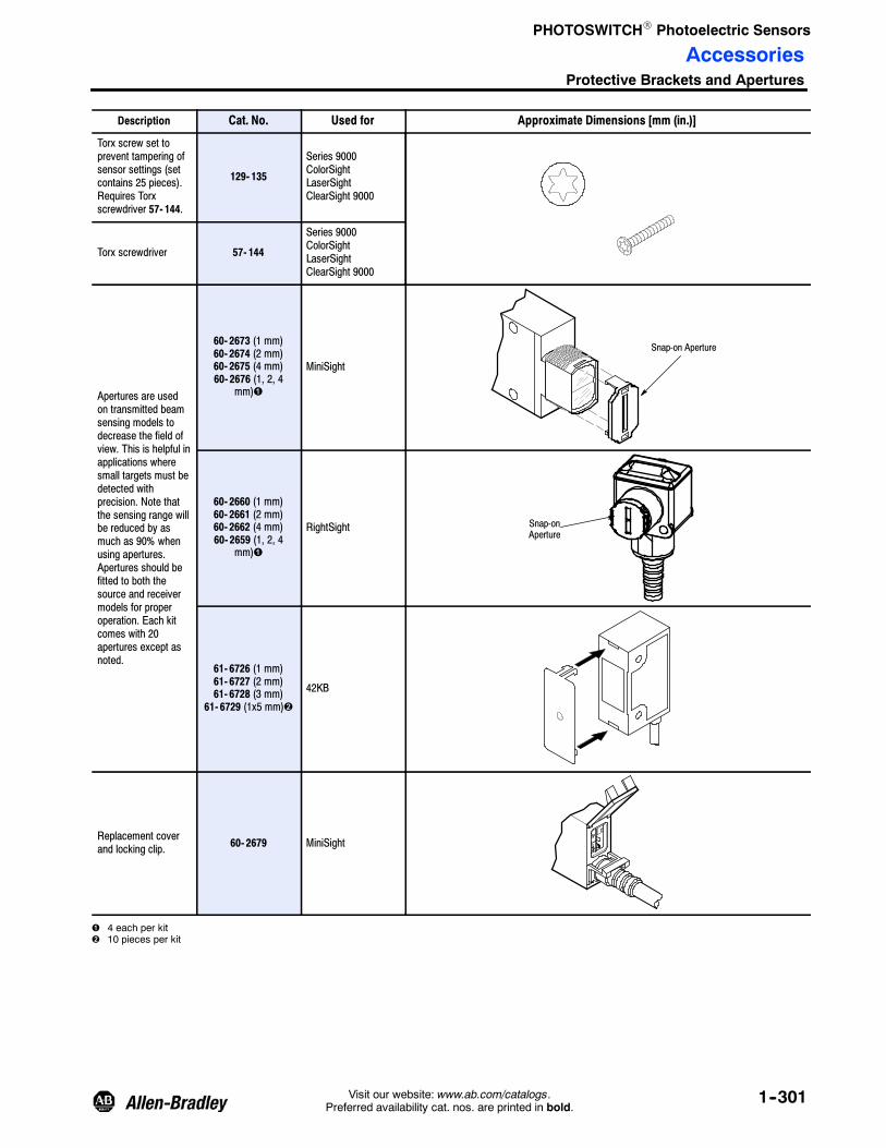
PHOTOSWITCHR Photoelectric Sensors
AccessoriesProtective Brackets and Apertures
1--301Visit our website: www.ab.com/catalogs.Preferred availability cat. nos. are printed in bold.
Description Cat. No. Used for Approximate Dimensions [mm (in.)]
Torx screw set toprevent tampering ofsensor settings (setcontains 25 pieces).Requires Torxscrewdriver 57- 144.
129- 135
Series 9000ColorSightLaserSightClearSight 9000
Torx screwdriver 57- 144
Series 9000ColorSightLaserSightClearSight 9000
Apertures are usedon transmitted beamsensing models todecrease the field ofview. This is helpful inapplications wheresmall targets must bedetected withprecision. Note thatthe sensing range willbe reduced by asmuch as 90% whenusing apertures.Apertures should befitted to both thesource and receivermodels for properoperation. Each kitcomes with 20apertures except asnoted.
60- 2673 (1 mm)60- 2674 (2 mm)60- 2675 (4 mm)60- 2676 (1, 2, 4
mm)
MiniSight
Snap-on Aperture
60- 2660 (1 mm)60- 2661 (2 mm)60- 2662 (4 mm)60- 2659 (1, 2, 4
mm)
RightSight Snap-onAperture
61- 6726 (1 mm)61- 6727 (2 mm)61- 6728 (3 mm)
61- 6729 (1x5 mm)
42KB
Replacement coverand locking clip. 60- 2679 MiniSight
4 each per kit10 pieces per kit
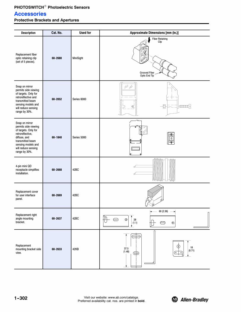
PHOTOSWITCHR Photoelectric Sensors
AccessoriesProtective Brackets and Apertures
1--302 Visit our website: www.ab.com/catalogs.Preferred availability cat. nos. are printed in bold.
Description Cat. No. Used for Approximate Dimensions [mm (in.)]
Replacement fiberoptic retaining clip(set of 5 pieces).
60- 2680 MiniSight
Fiber RetainingClip
Grooved FiberOptic End Tip
Snap on mirrorpermits side viewingof targets. Only forretroreflective andtransmitted beamsensing models andwill reduce sensingrange by 30%.
60- 2052 Series 6000
Snap on mirrorpermits side viewingof targets. Only forretroreflective,diffuse, andtransmitted beamsensing models andwill reduce sensingrange by 30%.
60- 1840 Series 5000
4-pin mini QDreceptacle simplifiesinstallation.
60- 2668 42BC
Replacement coverfor user interfacepanel.
60- 2669 42BC
Replacement rightangle mountingbracket.
60- 2637 42BC 28(1.1)
60 (2.36)
Replacementmounting bracket sideview.
60- 2633 42KB 18(0.71)
37.5(1.48)

PHOTOSWITCHR Photoelectric Sensors
AccessoriesProtective Brackets and Apertures
1--303Visit our website: www.ab.com/catalogs.Preferred availability cat. nos. are printed in bold.
Description Cat. No. Used for Approximate Dimensions [mm (in.)]
Replacementmounting bracket endview.
60- 2632 42KB 21.5(0.85)
12.0(0.47)
24.0(0.94)
Replacementmounting bracket. 60- 2635 42KC
Replacementmounting bracket endview.
60- 2634 42KC14
(0.55)
30 (1.18)
Replacement rightangle mountingbracket.
60- 2636 42BA14
(0.55)
30 (1.18)
Replacementreflector. 92- 93 42KB
42KC
Conduit mountingadaptor permitsconnection of sensorto 1/2 in. NPTconduit. Gasketed tomaintain NEMA 4rating.
60- 2213 Series 5000

PHOTOSWITCHR Photoelectric Sensors
AccessoriesProtective Brackets and Apertures
1--304 Visit our website: www.ab.com/catalogs.Preferred availability cat. nos. are printed in bold.
Description Cat. No. Used for Approximate Dimensions [mm (in.)]
Adaptor contains 3 m(10 ft) or armouredcable to protect PVCcable found on Series5000 cable stylebases.
60- 1577 Series 5000
Counter/Totalizermodule providesreliable high-speedcounting capabilityand six digit, 5 mmhigh, LCD display.Battery powered forminimum 5 year life.
60- 2072 Series 5000 GreenLine
Replacement adaptorpermits mounting ofsensor to 35 mm DINrail.
60- 263842FT45FVL45FSL
11.0(0.4)
5.2(0.2)
3.2(0.1)
12.0±0.2(0.5)
Dia. 3.2 (0.1) x5.2 (0.2)2 Places
16.0(0.6)
Replacement adaptorpermits mounting ofsensor to 35 mm DINrail.
60- 2639 42FA9.11(0.36)
56.0 (2.20)
30.0 (1.18)
12.5(0.49)
10.5(0.4)
6.0(0.24)
3.2 (0.125)diameter mounting holes
2 places
35 mm DIN rail (1 m)for mounting sensorand other controlequipment.
64- 13442FT45FVL45FSL

PHOTOSWITCHR Photoelectric Sensors
AccessoriesMounting Brackets and Reflectors
1--305Visit our website: www.ab.com/catalogs.Preferred availability cat. nos. are printed in bold.
Description Cat. No. Used for Approximate Dimensions [mm (in.)]
Right angle reflectorbracket set formounting up to 3 in.diameter reflectors.
60- 2717
92--3992--8992--4692--4792--10592--106
304.8(12.0)
101.6(4.0)
Reflector verticalheight adjustmentbracket for mountingup to 3 in. diameterreflectors.
60- 2718 (2 x 8 in.)60- 2719 (2 x 10 in.)60- 2720 (2 x 12 in.)
92--3992--8992--4692--4792--10592--106
H
101.6(4.0)
50.8(2.0)
152.4(6.0)
Reflector bracketprovides both verticaland horizontal heightadjustment. Bracketcomes with 3 in.reflector Cat. No.92--39.
60- 2685
92--3992--8992--4692--4792--10592--106
Base Bracket
Reflector
Clamp Bracket
Mounting bracket withCat. No. 92--47reflector mounted atright angle
60- 2692 92--47
92--47 Reflector
60--2657 RightAngle Bracket
35.8(1.41)
42.4(1.67)
Right angle mountingbracket for bothreflectors and fiberoptic cables
60- 2696
92--10592--10692--4792--46
31.8(1.25)
25.4(1.0)
38.1(1.5)
42.8(1.7)
6mm Dia.

PHOTOSWITCHR Photoelectric Sensors
AccessoriesReflectors, Reflective Tape
1--306 Visit our website: www.ab.com/catalogs.Preferred availability cat. nos. are printed in bold.
Specifications Approximate Dimensions [mm (in.)]
Cat. No. 92- 39 92- 124
4.8(0.19)
78(3.063)
84(3.3)
9(0.35)
Description Reflector, 76 mm (3 in.) dia. with center mounthole. (Plastic back) (ABS)
Suitable for Polarized Sensor Yes
Cube Style Corner cube
Optimum Range 150 mm (6 in.)…2 m (80 in.)
Recommended Application Suitable for general purpose applications up to65°C (150°F).
Cat. No. 92- 89
Description Reflector, 76 mm (3 in.) dia. with center mounthole. (Aluminum back)
Suitable for Polarized Sensor Yes
Cube Style Corner cube
Optimum Range 150 mm (6 in.)…2 m (80 in.)
Recommended Application Suitable for general purpose applications up to65°C (150°F).
Cat. No. 92- 47
31.8 (1.250)
#92-47
5.3(0.22)
35.81(1.41)
2.5(0.10)
Description Reflector, 32 mm (1.25 in.) dia. Requiresadhesive backing.
Suitable for Polarized Sensor Yes
Cube Style Corner cube
Optimum Range 150 mm (6 in.)…1.5 m (5 ft)
Recommended Application Suitable for general purpose applications up to65_C (150_F).
Cat. No. 92- 105
#92-105
10.2(0.4)
34.5(1.36)
10.0(0.4)
M5
Description Reflector, 32 mm (1.25 in.) dia. with M5 screw
Suitable for Polarized Sensor Yes
Cube Style Corner cube
Optimum Range 150 mm (6 in.)…1.5 m (5 ft)
Recommended Application Suitable for general purpose applications up to65_C (150_F).
Optimum range varies with sensor optics. See table on page 1--315 for reflectivity performance.

PHOTOSWITCHR Photoelectric Sensors
AccessoriesReflectors, Reflective Tape
1--307Visit our website: www.ab.com/catalogs.Preferred availability cat. nos. are printed in bold.
Specifications Approximate Dimensions [mm (in.)]
Cat. No. 92- 106
#92-106
7.4(0.3)
34.5(1.36)
12.6(0.5)
5.5(0.22)
Description Reflector, 32 mm (1.25 in.) dia. with snap fitpost
Suitable for Polarized Sensor Yes
Cube Style Corner cube
Optimum Range 150 mm (6 in.)…1.5 m (5 ft)
Recommended Application Suitable for general purpose applications up to65_C (150_F).
Cat. No. 92- 46
#92-46
15.9(0.625)
5.3(0.22)
20.8(0.82)
2.8(0.11)
Description Reflector, 16 mm (0.625 in.) dia. Requiresadhesive backing.
Suitable for Polarized Sensor Yes
Cube Style Corner cube
Optimum Range 51 mm (2 in.)…150 mm (6 in.)
Recommended Application Suitable for general purpose applications up to65_C (150_F).
Cat. No. 92- 90
#92-90
9(0.354)
86(3.38)
74(2.91)
63(2.48)
∅4.3(0.169)
Description Reflector, 86 mm (3 in.) dia. with mountingtabs.
Suitable for Polarized Sensor Yes
Cube Style Corner cube
Optimum Range 51 mm (2 in.)…1.5 m (5 ft)
Recommended ApplicationSuitable for ClearSight photoelectric sensorsand general purpose applications up to 65_C(150_F).
Cat. No. 92- 114
#92-114
7.4(0.3)
34.5(1.36)2.8
(0.11)
0.8(0.03)
Description Reflector, 34 mm (1.35 in.) dia. Requiresadhesive backing.
Suitable for Polarized Sensor Yes
Cube Style Micro cube
Optimum Range
Recommended ApplicationIdeal for laser-based photoelectric sensorssuch as LaserSight as well as general purposeapplications up to 65_C (150_F).
Optimum range varies with sensor optics. See table on page 1--315 for reflectivity performance.Cat. Nos. 92--47 and 92--46 can be mounted with adhesive tape (not included).

PHOTOSWITCHR Photoelectric Sensors
AccessoriesReflectors, Reflective Tape
1--308 Visit our website: www.ab.com/catalogs.Preferred availability cat. nos. are printed in bold.
Specifications Approximate Dimensions [mm (in.)]
Cat. No. 92- 115
#92-115
7.4(0.3) 34.5
(1.36)12.6(0.5)
6.5(0.26)
~2--3
Description Reflector, 34 mm (1.35 in.) dia. with snap fitpost.
Suitable for Polarized Sensor Yes
Cube Style Micro cube
Optimum Range
Recommended ApplicationIdeal for laser-based photoelectric sensorssuch as LaserSight as well as general purposeapplications up to 65_C (150_F).
Cat. No. 92- 116
#92-116
9.2(0.36)
34.5(1.36)
8.4(0.33)
M5
Description Reflector, 34 mm (1.35 in.) dia. with threadedpost.
Suitable for Polarized Sensor Yes
Cube Style Micro cube
Optimum Range
Recommended ApplicationIdeal for laser-based photoelectric sensorssuch as LaserSight as well as general purposeapplications up to 65_C (150_F).
Cat. No. 92- 109
#92-109
51(2.01)
8(0.32)
51.5(2.03)
5.2(0.21)
4.3(0.17)
61(2.40)
20(0.79)
10(0.39)
DescriptionReflector, 51 x 61 mm (2 x 2.5 in.) rectangularwith mounting tabs.
Suitable for Polarized Sensor Yes
Cube Style Corner cube
Optimum Range 51 mm (2 in.)…3.0 m (10 ft)
Recommended ApplicationSuitable for general purpose applications up to65_C (150_F).
Cat. No. 92- 118
#92-118
40.0(1.58)
51.0(2.01)
10 (0.39)
51.0 (2.01)38.0 (1.50)
3.5(0.14)
60.7(2.39)
7.0(0.28)
20 (0.79)
Description Reflector, 51 x 61 mm (2 x 2.5 in.) rectangularwith mounting tabs.
Suitable for Polarized Sensor Yes
Cube Style Micro cube
Optimum Range
Recommended Application
Suitable for general purpose applications up to65_C (150_F). The Cat. No. 92--118 is alsosuitable for laser-based photoelectric sensorssuch as LaserSight.
Optimum range varies with sensor optics. See table on page 1--315 for reflectivity performance.

PHOTOSWITCHR Photoelectric Sensors
AccessoriesReflectors, Reflective Tape
1--309Visit our website: www.ab.com/catalogs.Preferred availability cat. nos. are printed in bold.
Specifications Approximate Dimensions [mm (in.)]
Cat. No. 92- 108
92(3.62)
92(3.62)
3.5(0.14)
9(0.35)
#92-108
100(4)
100(4)
DescriptionReflector, 100 x 100 mm (4 x 4 in.) squarewith mounting tabs.
Suitable for Polarized Sensor Yes
Cube Style Corner cube
Optimum Range 150 mm (6 in.)…3.0 m (10 ft)
Recommended ApplicationSuitable for general purpose applications up to65_C (150_F).
Cat. No. 92- 1076.5(0.26)
4(0.16) 120
(4.72)
110(4.33)
#92-107
18.5(0.73)
DescriptionReflector, 18.5 x 120 mm (0.73 x 4.72 in.)rectangular with mounting tabs.
Suitable for Polarized Sensor Yes
Cube Style Corner cube
Optimum Range 51 mm (2 in.)…1.5 m (5 ft)
Recommended ApplicationSuitable for general purpose applications up to65_C (150_F).
Cat. No. 92- 93
25(0.98)
21.3(0.84)
5(0.2)14
(0.55)#60--2635 mounting
bracket, hardware, andadhesive supplied with
reflector
7(0.28)
Clearancefor M3hardware(supplied)
12(0.47)
42.5(1.67)
23(0.91)
9.5(0.37)
#92-93
30.8(1.21)
DescriptionReflector, 23 x 42.5 mm (0.91 x 1.67 in.)rectangular with mounting tabs and bracket.Right angle bracket and adhesive tape.
Suitable for Polarized Sensor Yes
Cube Style Corner cube
Optimum Range 51 mm (2 in.)…150 mm (6 in.)
Recommended ApplicationSuitable for general purpose applications up to55_C (130_F).
Optimum range varies with sensor optics. See table on page 1--315 for reflectivity performance.

PHOTOSWITCHR Photoelectric Sensors
AccessoriesReflectors, Reflective Tape
1--310 Visit our website: www.ab.com/catalogs.Preferred availability cat. nos. are printed in bold.
Specifications Approximate Dimensions [mm (in.)]
Cat. No. 92- 111
19(0.75)
3.5(0.14)
72.5 (2.85)
8.4(0.33)
63.0 (2.48)
54.0 (2.13)
3.5(0.14)
#92-111
Description Reflector, 19 x 72.5 mm (0.75 x 2.85 in.)rectangular with mounting tabs.
Suitable for Polarized Sensor Yes
Cube Style Corner cube
Optimum Range
Recommended Application Suitable for general purpose applications up to55_C (130_F).
Cat. No. 92- 112
23.5(0.92)
3.5(0.14)
55.0 (2.17)
8.0(0.31)
48.0 (1.89)
40.0 (1.58)
3.5(0.14)
#92-112
Description Reflector, 23.5 x 55 mm (0.924 x 2.17 in.)rectangular with mounting tabs.
Suitable for Polarized Sensor Yes
Cube Style Corner cube
Optimum Range
Recommended Application Suitable for general purpose applications up to55_C (130_F).
Cat. No. 92- 113
52.0(2.05)
3.5(0.14)
40.5 (1.6)
34.0 (1.34)
3.5(0.14)
60.0(2.36)
7.2(0.28)
#92-113
Description Reflector, 40.5 x 60 mm (1.6 x 2.36 in.)rectangular with mounting tabs.
Suitable for Polarized Sensor Yes
Cube Style Corner cube
Optimum Range
Recommended Application Suitable for general purpose applications up to55_C (130_F).
Cat. No. 92- 117
52.0(2.05)
3.5(0.14)
40.0 (1.58)
34.0 (1.34)
3.5(0.14)
60.0(2.36)
4.8(0.19)
40.0(1.58)
#92-117
Description Reflector, 40.5 x 60 mm (1.6 x 2.36 in.)rectangular with mounting tabs.
Suitable for Polarized Sensor Yes
Cube Style Micro cube
Optimum Range
Recommended Application
Suitable for general purpose applications up to55_C (130_F). The 92- 117 is also suited forlaser-based photoelectric sensors such asLaserSight.
Optimum range varies with sensor optics. See table on page 1--315 for reflectivity performance.

PHOTOSWITCHR Photoelectric Sensors
AccessoriesReflectors, Reflective Tape
1--311Visit our website: www.ab.com/catalogs.Preferred availability cat. nos. are printed in bold.
Specifications Approximate Dimensions [mm (in.)]
Cat. No. 92- 119
#92-119
50.6(1.99)
101.0(3.98)
7.5(0.3)
DescriptionReflector, 51 x 101 mm (2 x 4 in.) rectangularwith adhesive backing.
Suitable for Polarized Sensor Yes
Cube Style Corner cube
Optimum Range
Recommended ApplicationSuitable for general purpose applications up to65_C (150_F).
Cat. No. 92- 97 50.8(2.00)
50.8(2.00)
#92-97
DescriptionReflective tape, 51 mm (2 in.) square, sheet of16 pieces with adhesive backing.
Suitable for Polarized Sensor Yes
Cube Style Glass bead
Optimum Range 150 mm (6 in.)…1.5 m (5 ft)
Recommended ApplicationSuitable for general purpose applications up to121_C (250_F). Also suitable for polarizedretroreflective sensors.
Cat. No. 92- 91
101.6(4)
101.6(4)
#92-91
Description Reflective metal, 100 x 100 mm (4 x 4 in.)square.
Suitable for Polarized Sensor No
Cube Style Glass bead
Optimum Range 150 mm (6 in.)…1.5 m (5 ft)
Recommended ApplicationThe Cat. No. 92--91 is intended for use in hightemperature applications up to 480_C (900_F)but not with polarized retroreflective sensors.
Cat. No. 92- 98 76.2(3.00)
76.2(3.00)
#92-98
Description Reflective tape, 76 mm (2.75 in.) square,sheet of 9 pieces with adhesive backing.
Suitable for Polarized Sensor Yes
Cube Style Glass bead
Optimum Range 150 mm (6 in.)…1.5 m (5 ft)
Optimum range varies with sensor optics. See table on page 1--315 for reflectivity performance.

PHOTOSWITCHR Photoelectric Sensors
AccessoriesReflectors, Reflective Tape
1--312 Visit our website: www.ab.com/catalogs.Preferred availability cat. nos. are printed in bold.
Specifications Approximate Dimensions [mm (in.)]
Cat. No. 92- 104
279.4(11)
215.9(8.5)
#92-104
Description Reflective tape, 215.9 x 279.4 mm(8.5 x 11 in.) sheet with adhesive backing.
Suitable for Polarized Sensor Yes
Cube Style Glass bead
Optimum Range 200 mm (8 in.)…1.5 m (5 ft)
Recommended ApplicationSuitable for general purpose applications up to60_C (140_F) with polarized retroreflectivesensors.
Cat. No. 92- 99
25.4(1.00)
2540(100)
#92-99 & #92- 100
Description Reflective tape, roll of 25 x 2540 mm(1 x 100 in.).
Suitable for Polarized Sensor Yes
Cube Style Glass bead
Optimum Range 150 mm (6 in.)…1.0 m (40 in.)
Recommended Application Suitable for general purpose applications up to65_C (150_F).
Cat. No. 92- 100
Description Reflective tape, 25 x 2540 mm (1 x 100 in.).
Suitable for Polarized Sensor No
Cube Style Glass bead
Optimum Range 150 mm (6 in.)…1.0 m (40 in.)
Recommended Application Suitable for general purpose applications up to79_C (175_F).
Optimum range varies with sensor optics. See table on page 1--315 for reflectivity performance.
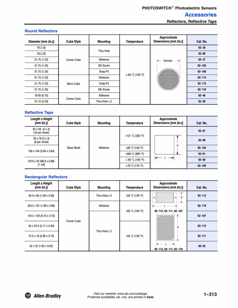
PHOTOSWITCHR Photoelectric Sensors
AccessoriesReflectors, Reflective Tape
1--313Visit our website: www.ab.com/catalogs.Preferred availability cat. nos. are printed in bold.
Round Reflectors
Diameter [mm (in.)] Cube Style Mounting TemperatureApproximate
Dimensions [mm (in.)] Cat. No.
76.2 (3)
Corner Cube
Thru-Hole
≤65_C (150_F)
Diameter
92- 39
76.2 (3) 92- 89
31.75 (1.25) Adhesive 92- 47
31.75 (1.25) M5 Screw 92- 105
31.75 (1.25) Snap-Fit 92- 106
31.75 (1.25)
Micro Cube
Adhesive 92- 114
31.75 (1.25) Snap-Fit 92- 115
31.75 (1.25) M5 Screw 92- 116
19.05 (0.75)Corner Cube
Adhesive 92- 46
57.15 (2.25) Thru-Hole x 2 92- 90
Reflective Tape
Length x Height[mm (in.)] Cube Style Mounting Temperature
ApproximateDimensions [mm (in.)] Cat. No.
50 x 50 (2 x 2)(16 per sheet)
Glass Bead Adhesive
<121_C (250_F)
H
L
92- 97
76 x 76 (3 x 3)(9 per sheet) 92- 98
100 x 100 (3.94 x 3.94)<60_C (140_F) 92- 104
<480_C (900_F) 92- 91
2510 x 25 (98.8 x 0.98)(1 roll)
≤65_C (150_F) 92- 99
<79_C (175_F) 92- 100
Rectangular Reflectors
Length x Height[mm (in.)] Cube Style Mounting Temperature
ApproximateDimensions [mm (in.)] Cat. No.
40.5 x 60 (1.59 x 2.36)
Corner Cube
Thru-Hole x 2 <55_C (130_F)
92- 112, 92- 111, 92- 107
H
L
92- 113, 92- 117, 92- 119
H
L
92- 113
50.6 x 101 (1.99 x 3.98) Adhesive
<65_C (150_F)
92- 119
18.5 x 120 (0.73 x 4.72)
Thru-Hole x 2
92- 107
55 x 23.5 (2.17 x 0.93)
<55_C (130_F)
92- 112
72.5 x 19 (2.85 x 0.75) 92- 111
42 x 22 (1.65 x 0.87) 92- 93

PHOTOSWITCHR Photoelectric Sensors
AccessoriesReflectors, Reflective Tape
1--314 Visit our website: www.ab.com/catalogs.Preferred availability cat. nos. are printed in bold.
Square Reflectors
Length x Height[mm (in.)] Cube Style Mounting Temperature
ApproximateDimensions [mm (in.)] Cat. No.
100 x 100 (3.94 x 3.94)
Corner Cube
Thru-Hole x 2 ≤65_C (150_F)92- 108, 92- 117
92- 109, 92- 118
H
L
H
L
92- 108
51.5 x 61 (2.08 x 2.40) 92- 109
40 x 60 (1.57 x 2.36) 92- 117
51 x 60.7 (2.01 x 2.39) Micro Cube 92- 118
For more detailed dimensions, please refer to www.ab.com/e- tools.
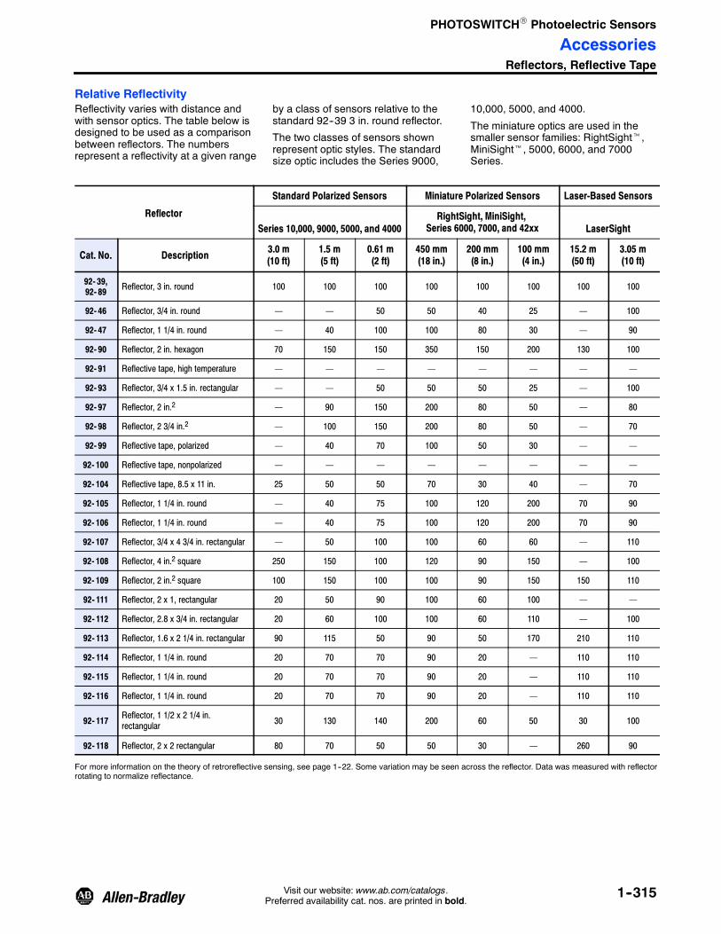
PHOTOSWITCHR Photoelectric Sensors
AccessoriesReflectors, Reflective Tape
1--315Visit our website: www.ab.com/catalogs.Preferred availability cat. nos. are printed in bold.
Relative ReflectivityReflectivity varies with distance andwith sensor optics. The table below isdesigned to be used as a comparisonbetween reflectors. The numbersrepresent a reflectivity at a given range
by a class of sensors relative to thestandard 92--39 3 in. round reflector.
The two classes of sensors shownrepresent optic styles. The standardsize optic includes the Series 9000,
10,000, 5000, and 4000.
The miniature optics are used in thesmaller sensor families: RightSightt,MiniSightt, 5000, 6000, and 7000Series.
Reflector
Standard Polarized Sensors Miniature Polarized Sensors Laser-Based Sensors
Series 10,000, 9000, 5000, and 4000RightSight, MiniSight,
Series 6000, 7000, and 42xx LaserSight
Cat. No. Description 3.0 m(10 ft)
1.5 m(5 ft)
0.61 m(2 ft)
450 mm(18 in.)
200 mm(8 in.)
100 mm(4 in.)
15.2 m(50 ft)
3.05 m(10 ft)
92- 39,92- 89 Reflector, 3 in. round 100 100 100 100 100 100 100 100
92- 46 Reflector, 3/4 in. round — — 50 50 40 25 — 100
92- 47 Reflector, 1 1/4 in. round — 40 100 100 80 30 — 90
92- 90 Reflector, 2 in. hexagon 70 150 150 350 150 200 130 100
92- 91 Reflective tape, high temperature — — — — — — — —
92- 93 Reflector, 3/4 x 1.5 in. rectangular — — 50 50 50 25 — 100
92- 97 Reflector, 2 in.2 — 90 150 200 80 50 — 80
92- 98 Reflector, 2 3/4 in.2 — 100 150 200 80 50 — 70
92- 99 Reflective tape, polarized — 40 70 100 50 30 — —
92- 100 Reflective tape, nonpolarized — — — — — — — —
92- 104 Reflective tape, 8.5 x 11 in. 25 50 50 70 30 40 — 70
92- 105 Reflector, 1 1/4 in. round — 40 75 100 120 200 70 90
92- 106 Reflector, 1 1/4 in. round — 40 75 100 120 200 70 90
92- 107 Reflector, 3/4 x 4 3/4 in. rectangular — 50 100 100 60 60 — 110
92- 108 Reflector, 4 in.2 square 250 150 100 120 90 150 — 100
92- 109 Reflector, 2 in.2 square 100 150 100 100 90 150 150 110
92- 111 Reflector, 2 x 1, rectangular 20 50 90 100 60 100 — —
92- 112 Reflector, 2.8 x 3/4 in. rectangular 20 60 100 100 60 110 — 100
92- 113 Reflector, 1.6 x 2 1/4 in. rectangular 90 115 50 90 50 170 210 110
92- 114 Reflector, 1 1/4 in. round 20 70 70 90 20 — 110 110
92- 115 Reflector, 1 1/4 in. round 20 70 70 90 20 — 110 110
92- 116 Reflector, 1 1/4 in. round 20 70 70 90 20 — 110 110
92- 117 Reflector, 1 1/2 x 2 1/4 in.rectangular 30 130 140 200 60 50 30 100
92- 118 Reflector, 2 x 2 rectangular 80 70 50 50 30 — 260 90
For more information on the theory of retroreflective sensing, see page 1--22. Some variation may be seen across the reflector. Data was measured with reflectorrotating to normalize reflectance.

PHOTOSWITCHR Photoelectric Sensors
Notes
1--316 Visit our website: www.ab.com/catalogs.Preferred availability cat. nos. are printed in bold.


