
Sensor and Motor Manual
Version: Botball 2011

Page 2
Copyright 2010 KISS Institute for Practical Robotics. All rights reserved.
KIPR makes no warranty for the use of its products and assumes no responsibility for any errors which
may appear in this document nor does it make a commitment to update the information contained
herein. KIPR products are not intended for use in medical, life saving or life sustaining applications. KIPR
retains the right to make changes to these specifications at any time, without notice.
BOTBALL®, BYO-BOT®, BOTGUY, and the BOTGUY design and character are trademarks and/or service
marks of KISS Institute for Practical Robotics and may not be used without express written permission.
LEGO, iRobot, and iRobot Create are registered marks of their respective owners.
The KISS Institute is a 501c3 nonprofit organization. Our mission is to improve the public's
understanding of science, technology, engineering, and math; develop the skills, character, and
aspirations of students; and contribute to the enrichment of our school systems, communities, and the
nation.

Page 3
Page 4
Contents
1. Overview ___________________________ 8
How to Use this Manual _____________________________________________________________ 8
What are Motors? _________________________________________________________________ 8
What are Sensors? _________________________________________________________________ 8
2. Motors _____________________________ 9
How does CBC sense the motor position? _______________________________________________ 9
What is a tick? ___________________________________________________________________________ 10
CS-60 Continuous Rotation Motor ____________________________________________________ 10
Performance _____________________________________________________________________________ 10
SG-5010 Continuous Rotation Motor _________________________________________________ 10
Performance _____________________________________________________________________________ 10
Uses ____________________________________________________________________________ 10
KISS-C Motor Library Functions ______________________________________________________ 11
Sample Code _____________________________________________________________________ 11
3. Servos ____________________________ 12
How does CBC sense the servo position? ______________________________________________ 12
Servo Precautions _________________________________________________________________________ 12
SG-5010 Standard Servo____________________________________________________________ 13
Performance _____________________________________________________________________________ 13
SG-90 Micro Servo ________________________________________________________________ 13
Performance _____________________________________________________________________________ 13
Uses ____________________________________________________________________________ 13
KISS-C Servo Library Functions _______________________________________________________ 14
Sample Code _____________________________________________________________________ 14
Page 5
4. Analog Sensors _____________________ 15
KISS-C Analog Sensor Library Functions _______________________________________________________ 15
The Light Sensor __________________________________________________________________ 16
Performance _____________________________________________________________________________ 16
Description ______________________________________________________________________________ 16
Uses____________________________________________________________________________________ 16
Sample code _____________________________________________________________________________ 16
The Large Top Hat Sensor __________________________________________________________ 17
Performance _____________________________________________________________________________ 17
Description ______________________________________________________________________________ 17
Uses____________________________________________________________________________________ 17
Sample Code 1 ___________________________________________________________________________ 18
Sample code 2 ___________________________________________________________________________ 18
The Small Top Hat Sensor __________________________________________________________ 19
Performance _____________________________________________________________________________ 19
Description ______________________________________________________________________________ 19
Uses____________________________________________________________________________________ 19
Sample Code 1 ___________________________________________________________________________ 20
Sample code 2 ___________________________________________________________________________ 20
The ET Sensor ____________________________________________________________________ 21
Performance _____________________________________________________________________________ 21
Description ______________________________________________________________________________ 21
Uses____________________________________________________________________________________ 21
Sample Code _____________________________________________________________________________ 22
The SONAR Sensor ________________________________________________________________ 23
Performance _____________________________________________________________________________ 23
Description ______________________________________________________________________________ 23
Uses____________________________________________________________________________________ 23
Sample Code _____________________________________________________________________________ 24

Page 6
5. Digital Sensors _____________________ 25
KISS-C Digital Sensor Library Functions ________________________________________________________ 25
The Slot Sensor ___________________________________________________________________ 26
Performance _____________________________________________________________________________ 26
Description ______________________________________________________________________________ 26
Uses____________________________________________________________________________________ 26
Sample Code 1 ___________________________________________________________________________ 26
Sample Code 2 ___________________________________________________________________________ 27
The Large Touch Sensor ____________________________________________________________ 28
Performance _____________________________________________________________________________ 28
Description ______________________________________________________________________________ 28
Uses____________________________________________________________________________________ 28
Sample Code _____________________________________________________________________________ 28
The Lever Sensor _________________________________________________________________ 29
Performance _____________________________________________________________________________ 29
Description ______________________________________________________________________________ 29
Uses____________________________________________________________________________________ 29
Sample Code _____________________________________________________________________________ 29
The Small Touch Sensor ____________________________________________________________ 30
Performance _____________________________________________________________________________ 30
Description ______________________________________________________________________________ 30
Uses____________________________________________________________________________________ 30
Sample Code _____________________________________________________________________________ 30
6. Accelerometer _____________________ 31
Performance _____________________________________________________________________________ 31
Description ______________________________________________________________________________ 31
Uses____________________________________________________________________________________ 31
Sample Code _____________________________________________________________________________ 31

Page 7
7. Camera ___________________________ 32
About vision tracking ______________________________________________________________ 32
Teaching the CBC v2 Color Channels __________________________________________________ 32
CBC v2 Vision Tracking Library Functions ______________________________________________ 35
Sample color tracking program if you have a servo ______________________________________ 36
Sample color tracking program if you do not have a servo ________________________________ 37
8. Troubleshooting ____________________ 38
9. Appendices ________________________ 39
Built in Motor Test ________________________________________________________________ 39
Built in Motor Position Display ______________________________________________________ 40
Checking Motor Polarity ___________________________________________________________ 41
Built in Servo Test _________________________________________________________________ 42
Finding the range of your servos _____________________________________________________ 43
Disabling the pull up resistors on the analog ports manually ______________________________ 44
Disabling the pull up resistors on the analog ports in your program _________________________ 45
KISS-C Library Functions for the CBC v2 _______________________________________________ 46
KISS-C Vision Library Functions for the CBC v2 __________________________________________ 51
Page 8
1. Overview How to Use this Manual
This manual is designed to illustrate how to use all of the Botball motors and sensors.
This manual can be read cover to cover as a primer on how to use motors and sensors. Each section
covers one type of device and then provides information about all of the similar devices provided in the
Botball kit.
This manual can also be used as a reference source. If you find yourself stuck on how to use a particular
motor or sensor, you should grab this manual and look up the offending device in the contents and flip
to that page.
What are Motors?
Motors take electrical energy and convert that to rotational mechanical energy. Botball uses two
different types of motors: continuous rotation motors and servos. Continuous rotation motors
constantly spin when electricity is applied. Servos can only rotate 180 degrees. They take electricity and
a signal indication what position to go to.
The CBC has 4 motor and 4 servo ports. The motor and sensor ports are split, two on each side of the
front of the CBC.
What are Sensors?
Sensors are devices that quantify measurements into observable signals. For Botball, the sensors will return a voltage between 0 and 5 volts DC to the CBC. The CBC divides that voltage either 2
8 or 2
10 times and generates a
number corresponding to the amount of feedback from the sensor. Two sensors can return the same value, but mean different things. The CBC has 8 analog and 8 digital sensor ports. All of the analog ports can be set to be floating analog ports eiter in a program, or manually. Sensors are plugged into the ports on the front of the CBC. Make sure that analog sensors are plugged into analog ports and digital sensors are plugged into digital ports. The CBC has a built in accelerometer sensor. The accelerometer can sense acceleration in three directions.

Page 9
2. Motors
The motors in the Botball kit will plug into any of the motor ports in any direction. When you instruct
the motor to drive forward the motor will turn and a blue light will come on (a red light indicates the
motor is being driven in reverse). If the motor is turning in the direction opposite of which you desire,
unplug the motor, rotate the connector 180 degrees and plug the connector back in.
The motor ports run at 6V with a max current draw of 1A per motor port. Each group of ports (0 and 1,
2 and 3) is controlled by a single h-bridge, so if you are going to be using close to 1A per motor, plug
them into ports controlled by different h-bridges (i.e. 0 and 3) to prolong the life of your h-bridges.
How does CBC sense the motor position?
The CBC uses a closed loop back EMF PID system. The closed loop means that the CBC is monitoring the
motor’s position. The CBC drives the motors with PWM commands. PWM stands for Pulse Width
Modulation. This is how you change the speed of the motor. Giving the motor full voltage drives it a full
speed and full power. Giving the motor half the voltage gives it half the speed and half the power.
Pulsing full power at 50% duty cycle drives the motor at full power at half speed, but also means that
the motor is only being powered 50% of the time. When the shaft is turned the motor will generate
power. The CBC can measure the power and determine the motor’s speed based on the amount of
power generated in the off cycle, this is called back EMF. PID stands for Proportional Integral Derivative
Control. The PID helps tune the CBC to the small imperfections in the motor giving better control over
the PWM functions.
Page 10
What is a tick?
A tick is the smallest measureable amount the motor can turn. Since the CBC V2 uses back EMF to
measure the motor position, the number of tics per motor is limited by the physical properties of the
motor and any internal gearing. The continuous rotation servo motors have about 1100 ticks per
revolution of the servo horn.
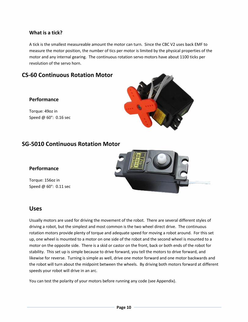
CS-60 Continuous Rotation Motor
Performance
Torque: 49oz in
Speed @ 60°: 0.16 sec
SG-5010 Continuous Rotation Motor
Performance
Torque: 156oz in
Speed @ 60°: 0.11 sec
Uses
Usually motors are used for driving the movement of the robot. There are several different styles of
driving a robot, but the simplest and most common is the two wheel direct drive. The continuous
rotation motors provide plenty of torque and adequate speed for moving a robot around. For this set
up, one wheel is mounted to a motor on one side of the robot and the second wheel is mounted to a
motor on the opposite side. There is a skid or castor on the front, back or both ends of the robot for
stability. This set up is simple because to drive forward, you tell the motors to drive forward, and
likewise for reverse. Turning is simple as well, drive one motor forward and one motor backwards and
the robot will turn about the midpoint between the wheels. By driving both motors forward at different
speeds your robot will drive in an arc.
You can test the polarity of your motors before running any code (see Appendix).

Page 11
KISS-C Motor Library Functions
See Appendix for complete list
motor(<motor#>,<power>)
Turns on a motor at a scaled PWM percentage. Power levels range from 100 (full forward) to -100 (full
backward).
mav(<motor#>,<velocity>)
Move At Velocity moves a motor at a velocity indefinitely. Velocities range from -1000 to 1000 ticks per
second. The MAV command will try to move the motor at a
ao()
All Off turns off power to all motor ports.
Sample Code
/*This program drives a two wheeled direct drive robot
forward for 3 seconds, stops, turns in place for half a
second, and stops for good. The motors are plugged into
ports 0 and 3 so that the robot moves forward when driven
forward. If the robot turns in place or drives backwards
at the beginning, unplug the offending motor plug and
rotate it 180 degrees and plug it back in.*/
int main(){
motor(0,100);//turn on motor in port 0 forward
motor(3,100);//turn on motor in port 3 forward
sleep(3.0); //wait for 3 seconds
ao(); //turn off both motors
mav(0,100); //turn on motor in port 0 forward
mav(3,-100); //turn on motor in port 3 backward
sleep(0.5); //wait for 0.5 seconds
ao(); //turn off both motors
}

Page 12
3. Servos
<=>
Servos plug in to the servo ports on the front of the CBC v2. The arrows used above represent the most
common coloring for servo cables: ground is black or brown, positive is red, and signal is yellow or
orange. The servos operate at 6 V.
How does CBC sense the servo position?
A servo has a control board inside it that controls the position. Inside the servo there is a physical
rotation sensor that senses the current servo position. A servo is provided an electrical pulse that
instructs the servo where to be positioned. The servo will try to go to and stay at the set position until
instructed otherwise or powered down. A standard servo has a range of about 180 degrees and 2048
positions in that range it can be set to.
Servo Precautions
The servo will try to get to the position it is set to even if it means straining or breaking the servo. Make
sure to not exceed the max torque limit of the servo, or damage will occur. When you first call the
enable_servo() command, if you have not specified a position, all servos will go to the middle position
(1024).

Page 13
SG-5010 Standard Servo
Performance
Torque: 156oz in
Speed @ 60°: 0.11 sec
SG-90 Micro Servo
Performance
Torque: 22oz in
Speed @ 60°: 0.11 sec
Uses
Servos are typically used in arms, claws, or other devices that require high precision and repeatability.
After setting a servo position, the program needs to wait for the servo to get to the desired position.
Since the servo has mechanical stops at 0 and 180 degrees, sometimes it is possible to “overdrive” a
servo. This means the mechanical stops are preventing the servo from reaching the desired position.
Overdriving causes the servo to buzz or hum and can cause permanent damage to the servo. You
should change the position you have set it to so that it does not buzz. A quiet servo is a happy servo.
See the Appendix for more information about finding your servo’s range.

Page 14
KISS-C Servo Library Functions
See Appendix for complete list
enable_servos()
Enables power to the servo ports. This must be called before servos will move. When this function is
called, the servo will default to position 1024 unless instructed to move elsewhere before enable_servos()
is called.
set_servo_position(<port#>, <position>)
Moves a servo plugged in a port to a position. Position ranges from 0 to 2047. The servo will immediately
move to position, unless impeded by external force. Call the enable_servos() function before using this
function.
Sample Code
/*This program moves two servos. Servos need to be plugged
into ports 0 and 3. The program presets servo 0 to position
150. Then the program waits for the black button to be
pushed. Then it enables servos, servo 0 goes to position
150 and servo 3 goes to 1900. Then servo 3 goes to 1900.
Finally servo 0 goes to 1900 and servo 3 goes to 150 and the
program ends. See appendix for finding your servo’s range.
int main(){
set_servo_position(0,150); //preset port 0 to 150
printf(“servo 0 at position 0\n”);
printf(“press black button to continue\n”);
while(!black_button()){} //wait for black button
enable_servos(); //enable the servos
sleep(1); //wait for servo to move
set_servo_position(3,1900); //move port 3 to 1900
sleep(1); //wait for servo to move
set_servo_position(0,1900); //move port 0 to 1900
set_servo_position(3,150); //move port 3 to 150
sleep(3); //wait for servos to move
disable_servos(); //power down servos
}

Page 15
4. Analog Sensors
Botball sensors are “keyed” so that there is only one orientation that all of the pins will be in holes.
Analog sensors can have two or three wires. In an analog sensor the resistance between the SEN and GND lines is
varied. The third wire is connected to VCC which powers the sensor.
Analog sensors will only return a good value if plugged into an analog port. The CBC can return the analog value in
either a 10 bit or 8 bit format. The 10 bit format is four times more accurate than the 8 bit format.
KISS-C Analog Sensor Library Functions
analog10(<port#>)
Returns the 10 bit analog value of the port (a value in the range 0-1023). Analog ports are numbered 0-7.
analog(<port#>)
Returns the8 bit analog value of the port (a value in the range 0-255). Analog ports are numbered 0-7.
set_each_analog_state(<port0>,<port1>,<port2>,<port3>,<port4>,<port5>,<port6>,<port7>)
This function is used to set whether or not the analog ports are set to floating points or to pullup resistors. Passing a 1 sets the corresponding port to floating. Please note that all sensor ports are set to non-floating when the CBC is rebooted or when a program exits. You only need to use this function if you are using floating point sensors, like the ET or SONAR sensors. When used, follow this statement with a short sleep command to allow time for the change to happen.

Page 16
The Light Sensor
Performance
Angular response: 20 degrees
Light sensitivity wavelength: 880 nm
Description
The light sensor is a variable resistor. Larger amounts of light increase the resistance of the sensor and
the CBC reports a low value.
Uses
The light sensor is used to start Botball robots at the beginning of the game. Several light sensors can be
used in an array to track changes in light, or to navigate a robot in relation to a fixed light source.
Sample code
/*This program runs the light calibration function. You
need a light sensor plugged into port 0 and a light to
shine at the light sensor. Follow the on screen
instructions to run the calibration code. Remember low
sensor values are light on and high values are light
off. After the calibration, the CBC beeps, prints a
message and beeps again. This program can also be run in
the simulator.*/
int main()
{
wait_for_light(0);
// wait for light sub routine using port 0
beep();
cbc_display_clear();
printf("Running Code\n");
beep();
}

Page 17
The Large Top Hat Sensor
Performance
Maximum detection distance: 15mm
Sensitivity wavelength: 940-850 nm
Description
The “Top Hat” sensor gets its name from the shape of the sensor. This sensor is really a short range
reflectance sensor. There is an IR emitter and an IR collector in this sensor. The IR emitter sends out IR
light and the IR emitter measures how much is reflected back.
Uses
This sensor has two uses. The first is as a line detector. Black materials typically absorb IR and reflect
very little IR back, and white materials typically absorb little IR and reflect most IR back. If this sensor is
mounted at a fixed height above a surface, it is easy to distinguish a black line from a white surface. The
second use is as a short range distance sensor. Be careful, as sometimes black objects close up look like
white objects far away. The Top Hat sensor works best when calibrated to black and white.
Amount of IR reflected back depends on surface texture, color and distance to surface. (See below)

Page 18
Sample Code 1
Sample code 2
/*This program demonstrates how to follow a line with a top hat
sensor. This is for a robot with the left motor in port 0, right
motor in port 3 and a top hat sensor in port 0 and mounted at
the front of the robot. This program uses bang-bang control. You
will need to adjust the threshold value to work for you (here it
is 512, right in the middle)*/
int main(){
while(1){ //loop forever
if(analog10(0)>=512){ //if the top hat sees light color
mav(0,750); //left motor fast
mav(3,100); //right motor slow
}
if(analog10(0)<512){ //if the top hat sees dark color
mav(0,100); //left motor slow
mav(3,750); //right motor fast
}
}
}
/*This program shows how to use a Top Hat sensor as a distance
sensor. This program drive motor 0 forward until the Top Hat
sensor in port 15 is triggered. If the sensor becomes un
triggered, the motor will move forward again. You can change 512
to be the distance you want to detect*/
int main()
{
while(1){ //loop forever
fd(0); //drive motor
while(analog10(0)>512){ //if sensor detects an object
ao();} //stop motor
}
}

Page 19
The Small Top Hat Sensor
Performance
Maximum detection distance: 12mm
Light sensitivity wavelength: 940-850 nm
Description
The small “Top Hat” sensor gets its name from the shape of its big brother sensor. Both sensors work
the same, but this is a smaller version with a shorter range. This sensor is really a short range
reflectance sensor. There is an IR emitter and an IR collector in this sensor. The IR emitter sends out IR
light and the IR emitter measures how much is reflected back.
Uses
This sensor has two uses. The first is as a line detector. Black materials typically absorb IR and reflect
very little IR back, and white materials typically absorb little IR and reflect most IR back. If this sensor is
mounted at a fixed height above a surface, it is easy to distinguish a black line from a white surface. The
second use is as a short range distance sensor. Be careful, as sometimes black objects close up look like
white objects far away. The Top Hat sensor works best when calibrated to black and white.
Amount of IR reflected back depends on surface texture, color and distance to surface. (See below)

Page 20
Sample Code 1
Sample code 2
/*This program demonstrates how to follow a line with a top hat
sensor. This is for a robot with the left motor in port 0, right
motor in port 3 and a top hat sensor in port 0 and mounted at
the front of the robot. This program uses bang-bang control. You
will need to adjust the threshold value to work for you (here it
is 512, right in the middle)*/
int main(){
while(1){ //loop forever
if(analog10(0)>=512){ //if the top hat sees light color
mav(0,750); //left motor fast
mav(3,100); //right motor slow
}
if(analog10(0)<512){ //if the top hat sees dark color
mav(0,100); //left motor slow
mav(3,750); //right motor fast
}
}
}
/*This program shows how to use a Top Hat sensor as a distance
sensor. This program drive motor 0 forward until the Top Hat
sensor in port 15 is triggered. If the sensor becomes un
triggered, the motor will move forward again. You can change 512
to be the distance you want to detect*/
int main()
{
while(1){ //loop forever
fd(0); //drive motor
while(analog10(0)>512){//while sensor detects an object
ao();} //stop motor
}
}

Page 21
The ET Sensor
Performance
Maximum detection distance: 80cm
Light sensitivity wavelength: 940-800 nm
Description
The “ET” sensor gets its name from the shape of the sensor resembling a famous movie Extra Terrestrial.
This sensor works by sending out a modulated frequency IR beam and measures the angle the reflected
IR light returns at and triangulates the distance to an object. Because of the modulated frequency, this
sensor is less susceptible to error due to changing lighting conditions.
Uses
!FLOATING PORT! See appendices on setting a port to floating!
This sensor makes a great medium range distance sensor. The sensor reads the highest value when it
detects an object at 5cm. The value decreases if your object gets closer or farther away (See below).
One way to fix that is to mount the sensor in such a way that nothing can get closer than 5cm.
Page 22
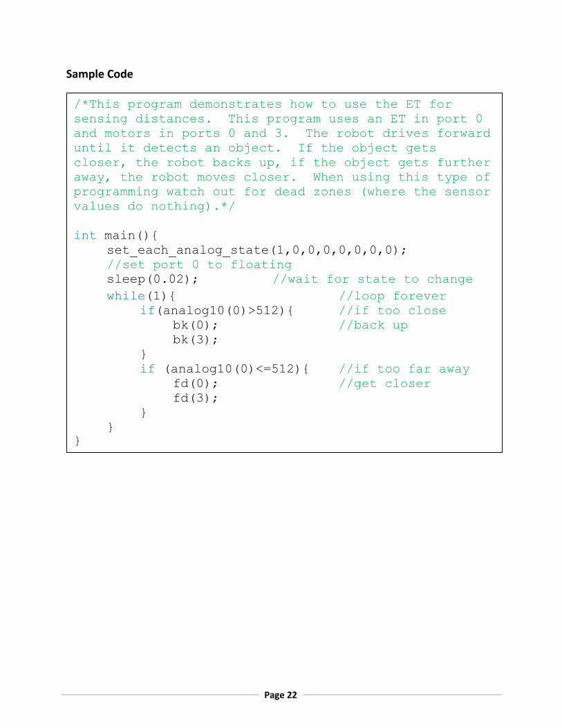
Sample Code
/*This program demonstrates how to use the ET for
sensing distances. This program uses an ET in port 0
and motors in ports 0 and 3. The robot drives forward
until it detects an object. If the object gets
closer, the robot backs up, if the object gets further
away, the robot moves closer. When using this type of
programming watch out for dead zones (where the sensor
values do nothing).*/
int main(){
set_each_analog_state(1,0,0,0,0,0,0,0);
//set port 0 to floating
sleep(0.02); //wait for state to change
while(1){ //loop forever
if(analog10(0)>512){ //if too close
bk(0); //back up
bk(3);
}
if (analog10(0)<=512){ //if too far away
fd(0); //get closer
fd(3);
}
}
}

Page 23
The SONAR Sensor
Performance
Detection Range: 6-254in
Refresh rate: 20Hz (or once every 50ms)
Description
The acronym SONAR stands for SOund Navigation And Ranging. The SONAR sensor works by sending
out a burst of ultrasonic sound (a ping) and measuring the amount of time it takes to hear the echo.
Then the sensor divides that time by the speed of sound and returns a distance. The pings from the
sonar radiate outwards as they travel giving the SONAR a conical measuring range (See below). Because
the SONAR sensor measures the time taken to hear an echo, the SONAR will return a value for the
closest item in the area of coverage, since it will hear that echo first. When called in the analog ()
function, the value returned roughly corresponds to the distance in inches.
Uses
!FLOATING PORT! See appendices on setting a port to floating!
The SONAR sensor is primarily used for distance detection. Because the SONAR sensor uses sound,
some objects may be invisible to the SONAR like Beanie Botguy. Beanie Botguy absorbs sound instead
of reflecting some back, so the sensor reads it as a really big open space. Objects that work well with
the SONAR sensor are hard smooth objects. A common use is to use a SONAR sensor and ET or Tophat
sensor to distinguish between hard and soft game elements. When the SONAR sensor is first plugged in,
or when the CBC boots, the sensor takes 350ms to calibrate. During that time, nothing should be closer
to the sensor than 17 inches, otherwise the reading could be off.

Page 24
Sample Code
/*This program demonstrates how to use the SONAR for
sensing distances. You need to plug the SONAR sensor into
port 0. This program beeps if anything changes from when
the program starts, i.e. if someone walks by. Remember -
when the SONAR is plugged in, or the CBC is turned on, the
SONAR needs about 17 inches of free space in front of it
for 350 ms while it calibrates.*/
int main(){
int i=0; //comparator variable
set_each_analog_state(1,0,0,0,0,0,0,0);
//set port 0 to floating
sleep(0.02); //wait for state to change
i=analog(0); //take initial SONAR reading
while(1){ //loop forever
if(analog(0)>(i+15)){ //if object moves away
beep();
}
if(analog(0)<(i-15)){ //if object moves closer
beep();
}
}
}
Page 25
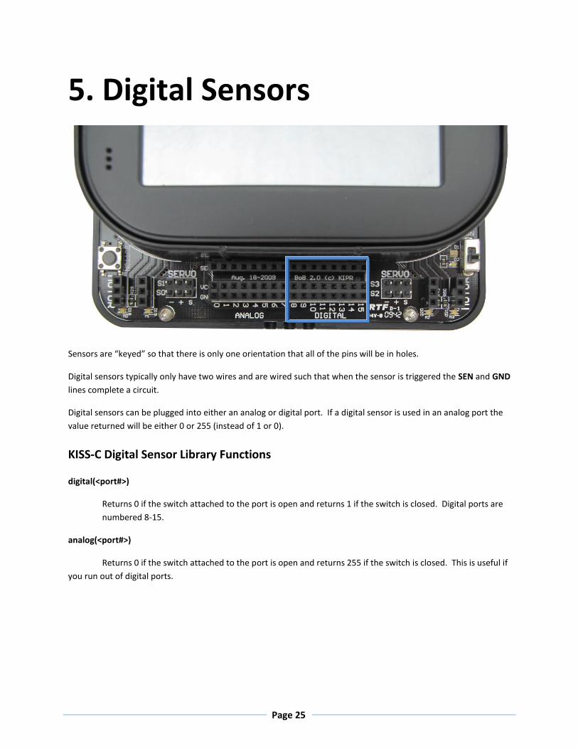
5. Digital Sensors
Sensors are “keyed” so that there is only one orientation that all of the pins will be in holes.
Digital sensors typically only have two wires and are wired such that when the sensor is triggered the SEN and GND
lines complete a circuit.
Digital sensors can be plugged into either an analog or digital port. If a digital sensor is used in an analog port the
value returned will be either 0 or 255 (instead of 1 or 0).
KISS-C Digital Sensor Library Functions
digital(<port#>)
Returns 0 if the switch attached to the port is open and returns 1 if the switch is closed. Digital ports are
numbered 8-15.
analog(<port#>)
Returns 0 if the switch attached to the port is open and returns 255 if the switch is closed. This is useful if
you run out of digital ports.

Page 26
The Slot Sensor
Performance
Sensitivity wavelength: 940-850 nm
Description
This sensor is an optical slot sensor. On one side of the U there is a IR emitter and on the other side a IR
detector. The sensor is triggered when the sensor beam is broken and the IR detector does not receive
a signal. Be careful when using this sensor because some objects do not block IR light.
Uses
This sensor has two main uses. The first is as an encoder. An encoder attaches a slotted wheel to the
driven wheel. The slot sensor records each time a slot goes by. The more slots the slotted wheel has,
the higher the resolution of the encoder. Encoders are used to passively measure if a wheel is turning,
or slipping. The second main use is as a limit detector. The sensor is used to detect if a moving part is
breaking the beam indicating that the moving part has moved to where it was intended.
Sample Code 1
/*This program shows how to use a slot sensor as an
encoder. An encoder counts the times that a slot
passes in front of the sensor. This program uses the
slot sensor in port 15 to count the number of times
triggered and prints it to the screen.*/
int main()
{
int i=0; //counter variable
while(1){ //loop forever
while(!digital(15)){} //wait until empty
while(digital(15)){} //wait until triggered
i++; //add 1 to the count
printf("triggered %d times\n",i); //print
}
}
Page 27
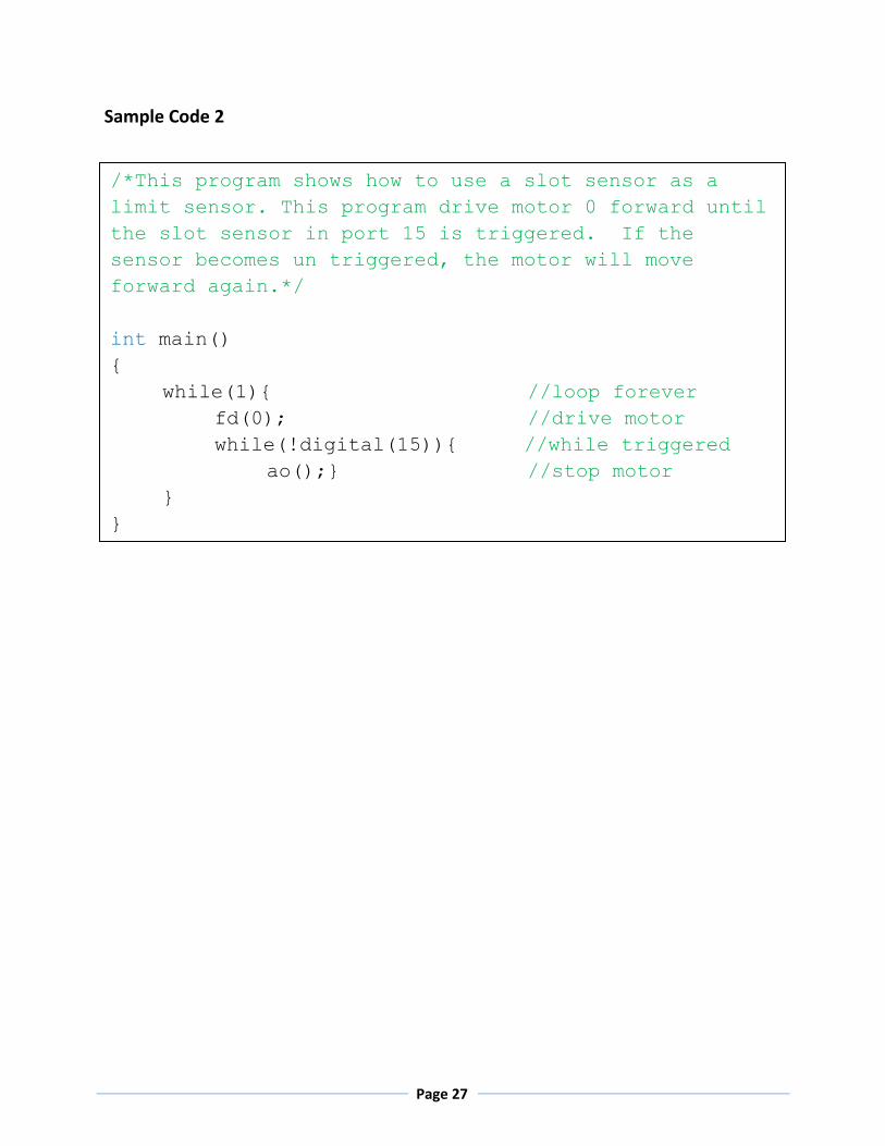
Sample Code 2
/*This program shows how to use a slot sensor as a
limit sensor. This program drive motor 0 forward until
the slot sensor in port 15 is triggered. If the
sensor becomes un triggered, the motor will move
forward again.*/
int main()
{
while(1){ //loop forever
fd(0); //drive motor
while(!digital(15)){ //while triggered
ao();} //stop motor
}
}
Page 28
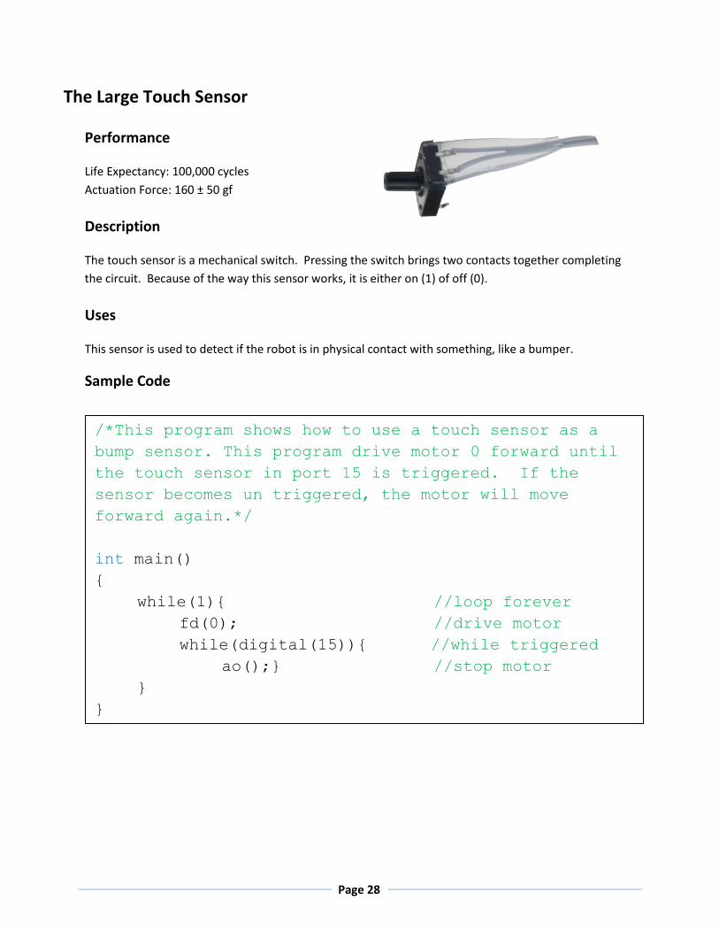
The Large Touch Sensor
Performance
Life Expectancy: 100,000 cycles
Actuation Force: 160 ± 50 gf
Description
The touch sensor is a mechanical switch. Pressing the switch brings two contacts together completing
the circuit. Because of the way this sensor works, it is either on (1) of off (0).
Uses
This sensor is used to detect if the robot is in physical contact with something, like a bumper.
Sample Code
/*This program shows how to use a touch sensor as a
bump sensor. This program drive motor 0 forward until
the touch sensor in port 15 is triggered. If the
sensor becomes un triggered, the motor will move
forward again.*/
int main()
{
while(1){ //loop forever
fd(0); //drive motor
while(digital(15)){ //while triggered
ao();} //stop motor
}
}

Page 29
The Lever Sensor
Performance
Life Expectancy: 50,000 cycles
Actuation Force: 5Gms. max.
Description
The touch sensor is a mechanical switch. Pressing the switch brings two contacts together completing
the circuit. Because of the way this sensor works, it is either on (1) of off (0).
Uses
This sensor is used to detect if the robot is in physical contact with something, like a bumper.
Sample Code
/*This program shows how to use a touch sensor as a
bump sensor. This program drive motor 0 forward until
the touch sensor in port 15 is triggered. If the
sensor becomes un triggered, the motor will move
forward again.*/
int main()
{
while(1){ //loop forever
fd(0); //drive motor
while(digital(15)){ //while triggered
ao();} //stop motor
}
}

Page 30
The Small Touch Sensor
Performance
Life Expectancy: 100,000 cycles
Actuation Force: 160 ± 50 gf
Description
The touch sensor is a mechanical switch. Pressing the switch brings two contacts together completing
the circuit. Because of the way this sensor works, it is either on (1) of off (0).
Uses
This sensor is used to detect if the robot is in physical contact with something, like a bumper.
Sample Code
/*This program shows how to use a touch sensor as a
bump sensor. This program drive motor 0 forward until
the touch sensor in port 15 is triggered. If the
sensor becomes un triggered, the motor will move
forward again.*/
int main()
{
while(1){ //loop forever
fd(0); //drive motor
while(digital(15)){ //while triggered
ao();} //stop motor
}
}

Page 31
6. Accelerometer Performance
Range: ±2G for each axis (x,y,z)
Description
A three axis accelerometer is built into the CBC. It constantly reports the X,Y and Z acceleration.
Acceleration is the change in speed over time, so constant speed has acceleration of 0. A reading of 50
is approximately 1 G.
Uses
The accelerometer is commonly used to sense impacts and CBC orientation.
Sample Code
/*This program shows how to use the accelerometer. The
accelerometer is built in, so you just need to load the
code on to your CBC. The CBC will beep and print a message
if turned upside down.*/
int main(){
while(1){ //loop forever
if(accel_z()<-50){ //if CBC reads -1G...
beep(); //usually only if upside down
printf("HELP! I'm Upside Down!\n");
sleep(0.5);
}
}
}

Page 32
7. Camera
About vision tracking
The CBC v2 has a built in color vision tracking system. A USB web camera provides images at a rate of about 5
frames per second to the CBC v2. The CBC v2 then does real time processing of the images. The CBC v2 processes
information on the 10 largest blobs on four color channels on each image. A blob is a group of adjacent pixels that
are in the same color channel. As each frame is processed the blob information is stored in variables you can
accesses to understand your environment. The color channels are taught to the CBC v2. The camera image size is
160 x 120. The upper left corner has coordinates (0,0) and the lower right has coordinates (159,119).
Teaching the CBC v2 Color Channels
While the CBC v2 is turned off, plug the USB camera into one of the USB A ports in the back of the CBC v2 as shown
below.
(0,0)
(159,119)
Page 33
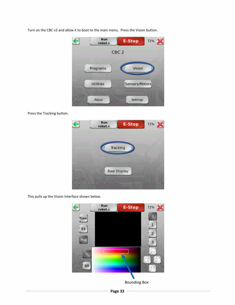
Turn on the CBC v2 and allow it to boot to the main menu. Press the Vision button.
Press the Tracking button.
This pulls up the Vision Interface shown below.
Bounding Box

Page 34
On the top right there are buttons numbered 0-3 indicating the four channels. On the top left there are three
buttons labeled Raw, Trk, and Mat. These stand for Raw camera image, Tracked camera image, and Matched
camera image respectively. The Raw camera image is exactly what the camera sees. The Tracked camera image
shows the pixels that fall into the bounding box area as white. The Matched camera image shows the pixels that
fall into the bounding box area as white, and when the number of touching pixels that fall into the bounding box is
greater than the minimum blob size shows a green bounding box around the blob and displays the centroid as a
green plus.
Teaching the CBC v2 a color channel is changing the area and the location of the bounding box in the bottom
center to encompass as many of the colors in the object to be tracked as well as limiting the number of non-
tracked colors in the box. The bounding box is controlled by the arrows in the bottom right and the TL and BR
buttons in the bottom right. TL and BR select which corner of the bounding box you are moving (Top Left or
Bottom Right). Due to the nature of the bounding box, the Bottom Right corner is trapped on the right side of the
HSV color selection plane, and the Top Left corner is trapped on the left side.
The HSV Color selection Plane (shown below) is a graphical representation of all of the colors the camera can see.
The Hue value describes the color (i.e. red, yellow, blue), and the Saturation and Value represent how dark or light
the color is (i.e. amout of black or white). Note that a value with a Saturation 224 and Value of 224 are the
brightest (or pure) colors that the camera can see.
Page 35
By default, the color channels are set to be a broad range of four popular (and easy to track) colors. Channel zero
is red, one is yellow, two is green, and three is blue. You should adjust the bounding box for the color models to fit
you specific application, but they give a good starting point.
When adjusting a color channel to your needs, first open the bounding box up so that the entire object you are
tracking is within the bounding box. When the entire object is inside the bounding box start reducing the
bounding box size to reduce the amount of environment being tracked. Note, that you may have to reduce the
amount of your object in the bounding box in order to keep the environment from being tracked. You will
probably not be tracking your whole object, due to inhomogeneous lighting conditions.
CBC v2 Vision Tracking Library Functions
These are the commonly used functions, for a complete list, see the appendix.
track_update()
Processes data for the current frame and make it available to the program. Always call this function
before using any other camera functions so they reference the current data.
track_count(<channel>)
Returns the number of blobs on a channel. Call track_update() first.
track_x(<channel>,<number>)
Returns the x coordinate of a blob on a channel. The blobs are ranked from 0 to 9 with 0 being the largest
blob size. Call track_update() first.
track_y(<channel>,<number>)
Returns the x coordinate of a blob on a channel. The blobs are ranked from 0 to 9 with 0 being the largest
blob size. Call track_update() first.

Page 36
Sample color tracking program if you have a servo
This sample program is a demo for using the camera on the CBC v2 if you have a servo. This program tracks an object on color channel 0 and points the servo at the object. If the object moves left the pointer points left.
Set Up
Attach the camera to the CBC v2. You need to set the color model on channel 0 to track an object you can move in front of the camera (the brighter the better). The servo needs to be set so that the pointer is just at edge of the camera’s field of view. The servo also needs to be pointed so that when the servo is set to the midpoint (1024) it points at the center of the camera’s field of view. For extra show use a pointer attached to the servo horn (of a color that is not in your color model). Finally download the program to the CBC v2.
Code
/* This program points a servo (that is plugged into port 0 and
centered on the camera’s field of vision) towards an object that
fits into the color model defined for channel 0*/
int main()
{
int offset, x, y;
enable_servos();
track_update(); // get most recent camera image and process it
while(black_button() == 0) {
x = track_x(0,0); // get image x data
y = track_y(0,0); // and y data
if(track_count(0) > 0) { // there is a blob
printf("Blob is at (%d,%d)\n",x,y);
offset=5*(x-80); //amount to deviate servo from center
set_servo_position(0,2014+offset);
}
else {
printf("No object in sight\n");
}
sleep(0.2); // don't rush print statement update
track_update(); // get new image data before repeating
}
disable_servos();
printf("All done\n");
}

Page 37
Sample color tracking program if you do not have a servo
This sample program is a demo for using the camera on the CBC v2 if you have a servo. This program tracks an object on color channel 0 and lights up the motor ports that correspond to the object’s location. If the object is in front of motor port 2 the motor port 2 light turns blue, and if the object moves to in front of motor port 1 the motor port 2 light turns off and the motor port 1 light comes on.
Set Up
Attach the camera to the CBC v2. You need to set the color model on channel 0 to track an object you can move in front of the camera (the brighter the better, but not blue). The camera needs to be pointed at the ground in front of the CBC v2 as close to the front as possible, without including the front of the CBC v2. The center of the camera’s field of vision needs to be aligned with the center of the CBC v2 as well. Finally, download the program to the CBC v2.
Code
/*For this program, point the camera so it is looking in front of the
motor ports on the CBC v2. This program turns on the motor light that
corresponds to the position of an object on channel 0. i.e. if an
object on channel 0 is in front of motor port 2 the motor 2 light will
come on. */
int main()
{
int x, xMax = 160;
while(black_button()==0){
track_update(); //get most recent camera image and process it
x = track_x(0,0); // get image x data
if(track_count(0)>0){ // there is a blob
printf("Blob x position is %d\n",x);
if(x >= 0 && x < (xMax/4)){ // if object is by motor 3
fd(3);}
else if(x >= (xMax/4) && x < (xMax/2)){ // object by 2
fd(2);}
else if(x >= (xMax/2) && x < ((3*xMax)/4)) // object by 1
fd(1);}
else if(x >= ((3*xMax)/4) && x <= xMax){ // object by 0
fd(0);}
}
sleep(0.1);
}
ao();
}
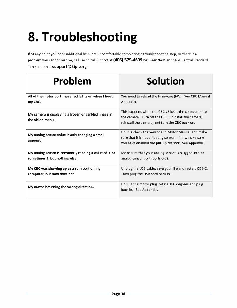
Page 38
8. Troubleshooting If at any point you need additional help, are uncomfortable completing a troubleshooting step, or there is a
problem you cannot resolve, call Technical Support at (405) 579-4609 between 9AM and 5PM Central Standard
Time, or email [email protected].
Problem Solution All of the motor ports have red lights on when I boot
my CBC.
You need to reload the Firmware (FW). See CBC Manual
Appendix.
My camera is displaying a frozen or garbled image in
the vision menu.
This happens when the CBC v2 loses the connection to
the camera. Turn off the CBC, uninstall the camera,
reinstall the camera, and turn the CBC back on.
My analog sensor value is only changing a small
amount.
Double check the Sensor and Motor Manual and make
sure that it is not a floating sensor. If it is, make sure
you have enabled the pull up resistor. See Appendix.
My analog sensor is constantly reading a value of 0, or
sometimes 1, but nothing else.
Make sure that your analog sensor is plugged into an
analog sensor port (ports 0-7).
My CBC was showing up as a com port on my
computer, but now does not.
Unplug the USB cable, save your file and restart KISS-C.
Then plug the USB cord back in.
My motor is turning the wrong direction. Unplug the motor plug, rotate 180 degrees and plug
back in. See Appendix.
Page 39
9. Appendices
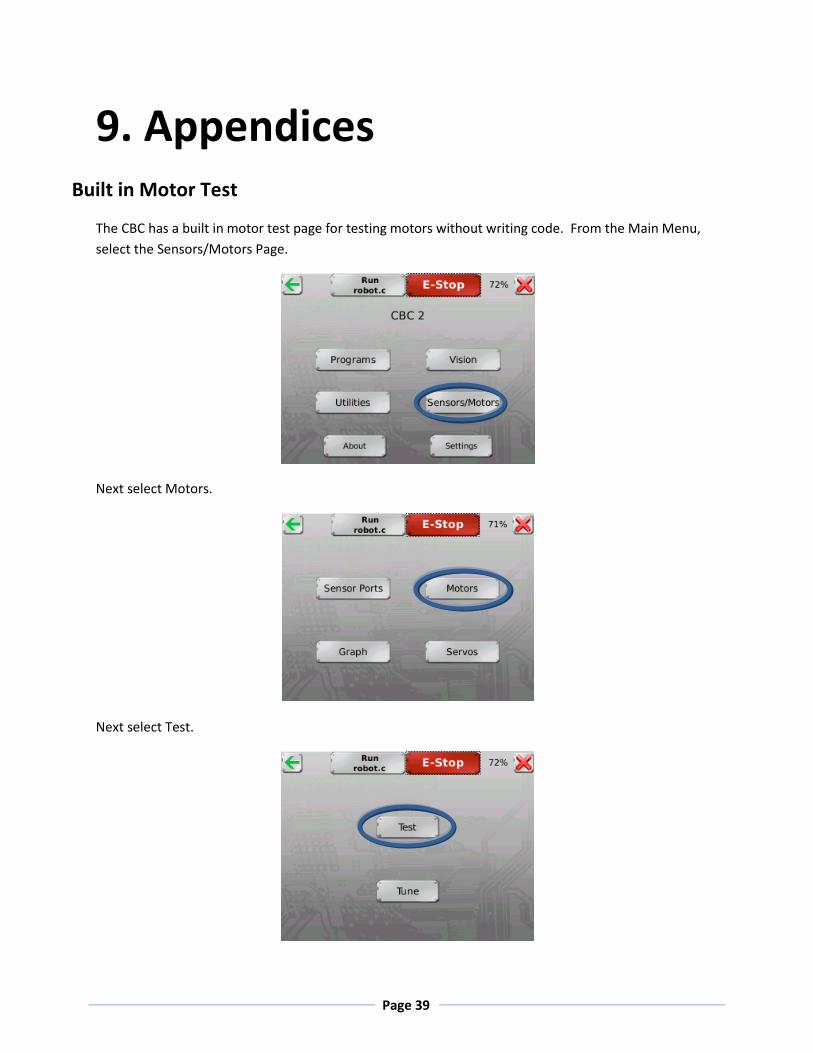
Built in Motor Test
The CBC has a built in motor test page for testing motors without writing code. From the Main Menu,
select the Sensors/Motors Page.
Next select Motors.
Next select Test.
Page 40
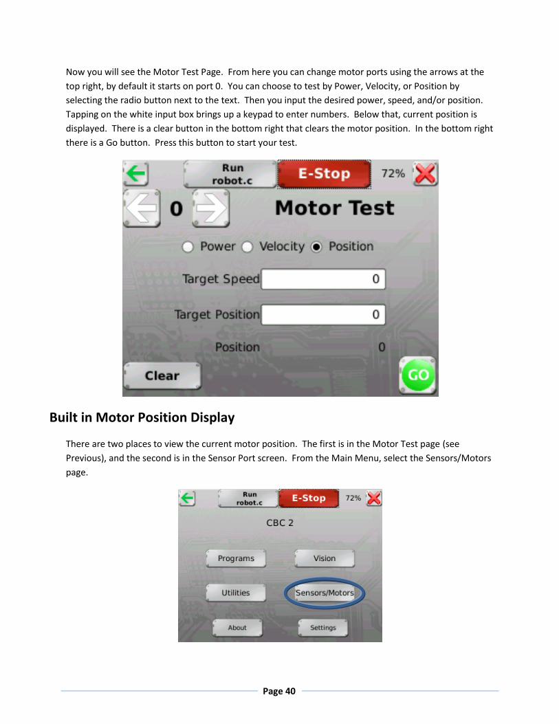
Now you will see the Motor Test Page. From here you can change motor ports using the arrows at the
top right, by default it starts on port 0. You can choose to test by Power, Velocity, or Position by
selecting the radio button next to the text. Then you input the desired power, speed, and/or position.
Tapping on the white input box brings up a keypad to enter numbers. Below that, current position is
displayed. There is a clear button in the bottom right that clears the motor position. In the bottom right
there is a Go button. Press this button to start your test.
Built in Motor Position Display
There are two places to view the current motor position. The first is in the Motor Test page (see
Previous), and the second is in the Sensor Port screen. From the Main Menu, select the Sensors/Motors
page.

Page 41
Next select Sensor Ports.
Now you will see the following screen.
The bottom of the screen provides information about current motor positions and currently supplied
motor powers.
Checking Motor Polarity
The CBC has no way to tell if the motor is driving the robot forward or backward. You will have to make
sure that the motors are plugged in correctly. There are many ways to do this. You can go to the Motor
Test Page (see Previous) and power a motor to make sure it is going in the correct direction. You can
use the Motor Position Display (see Previous) and turn the motor by hand to see if the position increases
(moving forward) or decreases (moving backward). Finally if you give the motor a quick turn, the LEDs in
front of the motor port will light up, blue for moving forward, and red for moving backwards. If you find
your polarity is reversed, you can unplug the motor rotate the plug 180 degrees and plug it back into the
motor port. The motor will now turn in the correct direction.

Page 42
Built in Servo Test
The CBC has a built in servo test page for testing servos without writing code. From the Main Menu,
select the Sensors/Motors Page.
Next select Servos.
Page 43
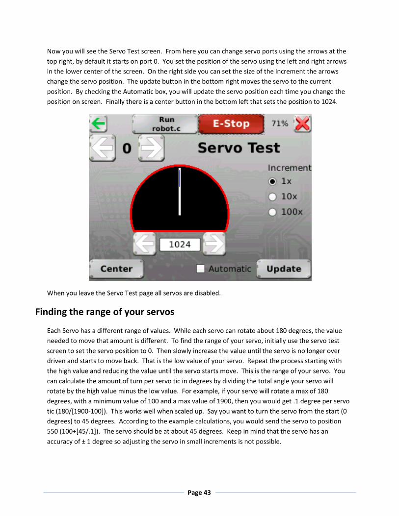
Now you will see the Servo Test screen. From here you can change servo ports using the arrows at the
top right, by default it starts on port 0. You set the position of the servo using the left and right arrows
in the lower center of the screen. On the right side you can set the size of the increment the arrows
change the servo position. The update button in the bottom right moves the servo to the current
position. By checking the Automatic box, you will update the servo position each time you change the
position on screen. Finally there is a center button in the bottom left that sets the position to 1024.
When you leave the Servo Test page all servos are disabled.
Finding the range of your servos
Each Servo has a different range of values. While each servo can rotate about 180 degrees, the value
needed to move that amount is different. To find the range of your servo, initially use the servo test
screen to set the servo position to 0. Then slowly increase the value until the servo is no longer over
driven and starts to move back. That is the low value of your servo. Repeat the process starting with
the high value and reducing the value until the servo starts move. This is the range of your servo. You
can calculate the amount of turn per servo tic in degrees by dividing the total angle your servo will
rotate by the high value minus the low value. For example, if your servo will rotate a max of 180
degrees, with a minimum value of 100 and a max value of 1900, then you would get .1 degree per servo
tic (180/[1900-100]). This works well when scaled up. Say you want to turn the servo from the start (0
degrees) to 45 degrees. According to the example calculations, you would send the servo to position
550 (100+[45/.1]). The servo should be at about 45 degrees. Keep in mind that the servo has an
accuracy of ± 1 degree so adjusting the servo in small increments is not possible.

Page 44
Disabling the pull up resistors on the analog ports manually
By default all of the analog pull up resistors are enabled. From the Main Menu, select the
Sensors/Motors page. Note that when the CBC v2 is reset the pull up resistors are disabled.
Next select Sensor Ports.
Now you will see the following screen.
Page 45
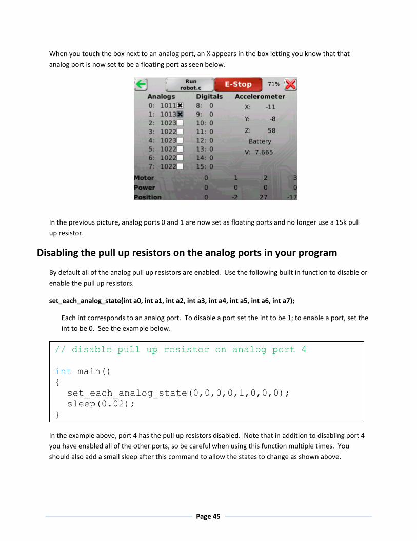
When you touch the box next to an analog port, an X appears in the box letting you know that that
analog port is now set to be a floating port as seen below.
In the previous picture, analog ports 0 and 1 are now set as floating ports and no longer use a 15k pull
up resistor.
Disabling the pull up resistors on the analog ports in your program
By default all of the analog pull up resistors are enabled. Use the following built in function to disable or
enable the pull up resistors.
set_each_analog_state(int a0, int a1, int a2, int a3, int a4, int a5, int a6, int a7);
Each int corresponds to an analog port. To disable a port set the int to be 1; to enable a port, set the
int to be 0. See the example below.
In the example above, port 4 has the pull up resistors disabled. Note that in addition to disabling port 4
you have enabled all of the other ports, so be careful when using this function multiple times. You
should also add a small sleep after this command to allow the states to change as shown above.
// disable pull up resistor on analog port 4
int main()
{
set_each_analog_state(0,0,0,0,1,0,0,0);
sleep(0.02);
}
Page 46
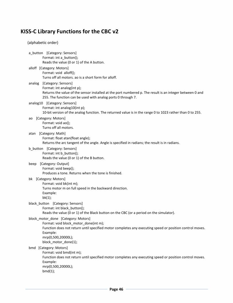
KISS-C Library Functions for the CBC v2
(alphabetic order)
a_button [Category: Sensors]
Format: int a_button(); Reads the value (0 or 1) of the A button.
alloff [Category: Motors]
Format: void alloff(); Turns off all motors. ao is a short form for alloff.
analog [Category: Sensors] Format: int analog(int p); Returns the value of the sensor installed at the port numbered p. The result is an integer between 0 and 255. The function can be used with analog ports 0 through 7.
analog10 [Category: Sensors]
Format: int analog10(int p); 10-bit version of the analog function. The returned value is in the range 0 to 1023 rather than 0 to 255.
ao [Category: Motors]
Format: void ao(); Turns off all motors.
atan [Category: Math]
Format: float atan(float angle); Returns the arc tangent of the angle. Angle is specified in radians; the result is in radians.
b_button [Category: Sensors]
Format: int b_button(); Reads the value (0 or 1) of the B button.
beep [Category: Output]
Format: void beep(); Produces a tone. Returns when the tone is finished.
bk [Category: Motors] Format: void bk(int m); Turns motor m on full speed in the backward direction. Example: bk(1);
black_button [Category: Sensors]
Format: int black_button(); Reads the value (0 or 1) of the Black button on the CBC (or a period on the simulator).
block_motor_done [Category: Motors] Format: void block_motor_done(int m); Function does not return until specified motor completes any executing speed or position control moves. Example: mrp(0,500,20000L); block_motor_done(1);
bmd [Category: Motors] Format: void bmd(int m); Function does not return until specified motor completes any executing speed or position control moves. Example: mrp(0,500,20000L); bmd(1);
Page 47
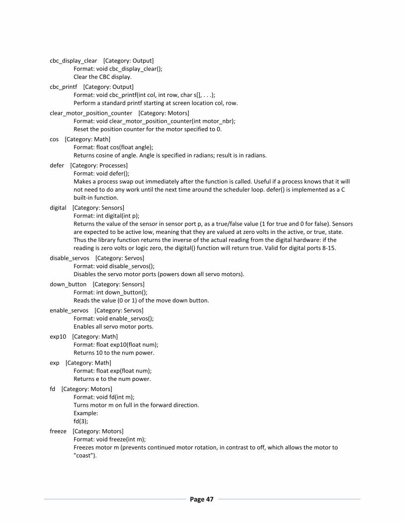
cbc_display_clear [Category: Output]
Format: void cbc_display_clear(); Clear the CBC display.
cbc_printf [Category: Output]
Format: void cbc_printf(int col, int row, char s[], . . .); Perform a standard printf starting at screen location col, row.
clear_motor_position_counter [Category: Motors]
Format: void clear_motor_position_counter(int motor_nbr); Reset the position counter for the motor specified to 0.
cos [Category: Math]
Format: float cos(float angle); Returns cosine of angle. Angle is specified in radians; result is in radians.
defer [Category: Processes] Format: void defer(); Makes a process swap out immediately after the function is called. Useful if a process knows that it will not need to do any work until the next time around the scheduler loop. defer() is implemented as a C built-in function.
digital [Category: Sensors] Format: int digital(int p); Returns the value of the sensor in sensor port p, as a true/false value (1 for true and 0 for false). Sensors are expected to be active low, meaning that they are valued at zero volts in the active, or true, state. Thus the library function returns the inverse of the actual reading from the digital hardware: if the reading is zero volts or logic zero, the digital() function will return true. Valid for digital ports 8-15.
disable_servos [Category: Servos]
Format: void disable_servos(); Disables the servo motor ports (powers down all servo motors).
down_button [Category: Sensors]
Format: int down_button(); Reads the value (0 or 1) of the move down button.
enable_servos [Category: Servos]
Format: void enable_servos(); Enables all servo motor ports.
exp10 [Category: Math]
Format: float exp10(float num); Returns 10 to the num power.
exp [Category: Math]
Format: float exp(float num); Returns e to the num power.
fd [Category: Motors] Format: void fd(int m); Turns motor m on full in the forward direction. Example: fd(3);
freeze [Category: Motors] Format: void freeze(int m); Freezes motor m (prevents continued motor rotation, in contrast to off, which allows the motor to "coast").

Page 48
get_motor_done [Category: Motors]
Format: int get_motor_done(int m); Returns whether the motor has finished a move with specified position.
get_motor_position_counter [Category: Motors] Format: int get_motor_position_counter(int m); Returns the current motor position value for motor m (a value which is continually being updated for each motor using back EMF; a typical discrimination for a given motor is on the order of 1100 position "ticks" per rotation)
get_servo_position [Category: Servos] Format: int get_servo_position(int srv); Returns the position value of the servo in port srv. The value is in the range 0 to 2047. There are 4 servo ports (0, 1, 2, 3).
kill_process [Category: Processes] Format: void kill_process(int pid); The kill_process function is used to destroy processes. Processes are destroyed by passing their process ID number to kill_process. If the return value is 0, then the process was destroyed. If the return value is 1, then the process was not found. The following code shows the main process creating a check_sensor process, and then destroying it one second later: int main(){ int pid; pid = start_process(check_sensor); sleep(1.0); kill_process(pid);}
kissSimEnablePause [Category: Simulator]
Format: void kissSimEnablePause(); Will pause the simulation if the space bar is pressed when this is called.
kissSimPause [Category: Simulator]
Format: void kissSimPause(); Will pause the simulation when this is called. Press the space bar to resume.
left_button [Category: Sensors]
Format: int left_button(); Reads the value (0 or 1) of the move left button.
log10 [Category: Math]
Format: float log10(float num); Returns the logarithm of num to the base 10.
log [Category: Math]
Format: float log(float num); Returns the natural logarithm of num.
mav [Category: Motors]
Format: void mav(int m, int vel); This function is the same as move_at_velocity
motor [Category: Motors] Format: void motor(int m, int p); Turns on motor m at scaled PWM duty cycle percentage p. Power levels range from 100 for full on forward to -100 for full on backward.
move_at_velocity [Category: Motors] Format: void move_at_velocity(int m, int vel); Moves motor m at velocity vel indefinitely. The velocity range is -1000 to 1000 ticks per second.

Page 49
move_relative_position [Category: Motors] Format: void move_relative_position(int m, int speed, int pos); Moves motor m at velocity vel from its current position curr_pos to curr_pos + pos. The speed range is 0 to 1000 ticks per second. Example: move_relative_position(1,275,-1100L);
move_to_position [Category: Motors] Format: void move_to_position(int m, int speed, int pos); Moves motor m at velocity vel from its current position curr_pos to pos. The speed range is 0 to 1000. Note that if the motor is already at pos, the motor doesn't move.
mrp [Category: Motors]
Format: void mrp(int m, int vel, int pos); This function is the same as move_relative_position.
mtp [Category: Motors]
Format: void mtp(int m, int vel, int pos); This function is the same as move_to_position.
msleep [Category: Time] Format: void msleep(int msec); Waits for an amount of time equal to or greater than msec milliseconds. Example: /*wait for 1.5 seconds */ msleep(1500);
off [Category: Motors] Format: void off(int m); Turns off motor m. Example: off(1);
power_level [Category: Sensor]
Format: float power_level(); Returns the current power level in volts.
printf [Category: Output]
Format: void printf(char s[], . . .); Prints the contents of the string referenced by s to the cursor position on the screen.
r_button [Category: Sensors]
Format: int r_button(); Reads the value (0 or 1) of the R (shoulder) button.
random [Category: Math]
Format: int random(int m); Returns a random integer between 0 and some very large number.
right_button [Category: Sensors]
Format: int right_button(); Reads the value (0 or 1) of the move right button.
run_for [Category: Processes] Format: void run_for(float sec, void <function_name>); This function takes a function and runs it for a certain amount of time in seconds. run_for will return within 1 second of your function exiting, if it exits before the specified time. The variable sec denotes how many seconds to run the given function.
seconds [Category: Time]
Format: float seconds(); Returns the count of system time in seconds, as a floating point number. Resolution is one millisecond.
Page 50
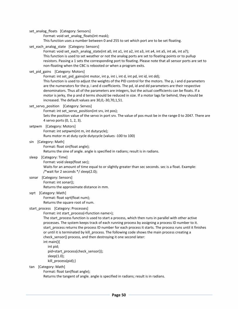
set_analog_floats [Category: Sensors]
Format: void set_analog_floats(int mask); This function uses a number between 0 and 255 to set which port are to be set floating.
set_each_analog_state [Category: Sensors] Format: void set_each_analog_state(int a0, int a1, int a2, int a3, int a4, int a5, int a6, int a7); This function is used to set weather or not the analog ports are set to floating points or to pullup resistors. Passing a 1 sets the corresponding port to floating. Please note that all sensor ports are set to non-floating when the CBC is rebooted or when a program exits.
set_pid_gains [Category: Motors] Format: int set_pid_gains(int motor, int p, int i, int d, int pd, int id, int dd); This function is used to adjust the weights of the PID control for the motors. The p, i and d parameters are the numerators for the p, i and d coefficients. The pd, id and dd parameters are their respective denominators. Thus all of the parameters are integers, but the actual coefficients can be floats. If a motor is jerky, the p and d terms should be reduced in size. If a motor lags far behind, they should be increased. The default values are 30,0,-30,70,1,51.
set_servo_position [Category: Servos] Format: int set_servo_position(int srv, int pos); Sets the position value of the servo in port srv. The value of pos must be in the range 0 to 2047. There are 4 servo ports (0, 1, 2, 3).
setpwm [Category: Motors]
Format: int setpwm(int m, int dutycycle); Runs motor m at duty cycle dutycycle (values -100 to 100)
sin [Category: Math]
Format: float sin(float angle); Returns the sine of angle. angle is specified in radians; result is in radians.
sleep [Category: Time] Format: void sleep(float sec); Waits for an amount of time equal to or slightly greater than sec seconds. sec is a float. Example: /*wait for 2 seconds */ sleep(2.0);
sonar [Category: Sensors]
Format: int sonar(); Returns the approximate distance in mm.
sqrt [Category: Math]
Format: float sqrt(float num); Returns the square root of num.
start_process [Category: Processes] Format: int start_process(<function name>); The start_process function is used to start a process, which then runs in parallel with other active processes. The system keeps track of each running process by assigning a process ID number to it. start_process returns the process ID number for each process it starts. The process runs until it finishes or until it is terminated by kill_process. The following code shows the main process creating a check_sensor() process, and then destroying it one second later: int main(){ int pid; pid=start_process(check_sensor()); sleep(1.0); kill_process(pid);}
tan [Category: Math]
Format: float tan(float angle); Returns the tangent of angle. angle is specified in radians; result is in radians.

Page 51
up_button [Category: Sensors]
Format: int up_button(); Reads the value (0 or 1) of the move up button.
KISS-C Vision Library Functions for the CBC v2
track_is_new_data_available [Category: Vision API]
Format: int track_is_new_data_available(); Returns 1 if new data is available since the last call of track_update(), 0 if no new data is available.
track_update [Category: Vision API]
Format: void track_update(); Processes tracking data for a new frame and makes it available for retrieval by the track_property() calls bellow.
track_get_frame [Category: Vision API]
Format: int track_get_frame(); Returns the frame number used to generate the tracking data.
track_count [Category: Vision API]
Format: int track_count(int ch); Returns the number of blobs available for the channel ch, which is a color channel numbered 0 through 3.
track_size [Category: Vision API]
Format: int track_size(int ch, int i); Returns the size of blob from channel ch (range 0-3), index i (range 0 to track_count(ch)-1) in pixels.
track_x [Category: Vision API]
Format: int track_x(int ch, int i); Returns the pixel x coordinate of the centroid for the blob from channel ch (range 0-3), index i (range 0 to track_count(ch)-1).
track_y [Category: Vision API]
Format: int track_y(int ch, int i); Returns the pixel y coordinate of the centroid for the blob from channel ch (range 0-3), index i (range 0 to track_count(ch)-1).
track_confidence [Category: Vision API]
Format: int track_confidence(int ch, int i); Returns the confidence for seeing the blob as a percentage of the blob pixel area/bounding box area (range 0-100, low numbers bad, high numbers good) for the blob from channel ch (range 0-3), index i (range 0 to track_count(ch)-1).

Page 52
track_bbox_left [Category: Vision API]
Format: int track_bbox_left(int ch, int i); Returns the pixel x coordinate of the leftmost pixel for the blob from channel ch (range 0-3), index i (range 0 to track_count(ch)-1).
track_bbox_right [Category: Vision API]
Format: int track_bbox_right(int ch, int i); Returns the pixel x coordinate of the rightmost pixel for the blob from channel ch (range 0-3), index i (range 0 to track_count(ch)-1).
track_bbox_top [Category: Vision API]
Format: int track_bbox_top(int ch, int i); Returns the pixel y coordinate of the topmost pixel for the blob from channel ch (range 0-3), index i (range 0 to track_count(ch)-1).
track_bbox_bottom [Category: Vision API]
Format: int track_bbox_bottom(int ch, int i); Returns the pixel y coordinate of the bottommost pixel for the blob from channel ch (range 0-3), index i (range 0 to track_count(ch)-1).
track_bbox_width [Category: Vision API]
Format: int track_bbox_width(int ch, int i); Returns the pixel x width of the bounding box for the blob from channel ch (range 0-3), index i (range 0 to track_count(ch)-1). This is equivalent to track_bbox_right - track_bbox_left.
track_bbox_height [Category: Vision API]
Format: int track_bbox_height(int ch, int i); Returns the pixel y height of the bounding box for the blob from channel ch (range 0-3), index i (range 0 to track_count(ch)-1). This is equivalent to track_bbox_bottom - track_bbox_top.
track_angle [Category: Vision API]
Format: int track_angle(int ch, int i); Returns the angle in radians of the major axis for the blob from channel ch (range 0-3), index i (range 0 to track_count(ch)-1). Zero is horizontal and when the left end is higher than the right end the angle will be positive. The range is -PI/2 to +PI/2.
track_major_axis [Category: Vision API]
Format: int track_major_axis(int ch, int i); Returns the length in pixels of the major axis of the bounding ellipse for the blob from channel ch (range 0-3), index i (range 0 to track_count(ch)-1).
track_minor_axis [Category: Vision API]
Format: int track_minor_axis(int ch, int i); Returns the length in pixels of the minor axis of the bounding ellipse for the blob from channel ch (range 0-3), index i (range 0 to track_count(ch)-1).


