
MAKING MODERN LIVING POSSIBLE
Service Manual
Series 51 - HZ, HA, HB, HE, HS, H1,H2, K1, K2, HP, HC, J1, J2, J3, J4, JAHydraulic Proportional Controls
powersolutions.danfoss.com

Revision history Table of revisions
Date Changed Rev
July 2014 Danfoss layout BA
November 2010 new last page AC
February 2010 Fix Osaka address AB
July 2009 First edition AA
Service Manual Series 51 Hydraulic Proportional Controls Service Manual
2 11009446 • Rev BA • July 2014
IntroductionSafety Precautions............................................................................................................................................................................5
Unintended Machine Movement..........................................................................................................................................5Flammable Cleaning Solvents................................................................................................................................................5Fluid Under Pressure..................................................................................................................................................................5Personal Safety.............................................................................................................................................................................5Hazardous Material.....................................................................................................................................................................5
Symbols used in Danfoss literature............................................................................................................................................6Overview..............................................................................................................................................................................................6General Instructions........................................................................................................................................................................ 7
Keep it Clean................................................................................................................................................................................. 7Inspect for System Contamination....................................................................................................................................... 7Replace the O-rings and Gaskets...........................................................................................................................................7Lubricate all Moving Parts........................................................................................................................................................7Torque Procedure....................................................................................................................................................................... 7
General Description.........................................................................................................................................................................7Overview........................................................................................................................................................................................ 7Threshold and Ramp Springs..................................................................................................................................................7Multiblock...................................................................................................................................................................................... 8Pressure Compensator OverRide (PCOR) Function........................................................................................................ 8Brake Pressure Defeat (BPD) Option.................................................................................................................................... 9
Pressure measurementsPort locations and Gauge Installation.................................................................................................................................... 10
AdjustmentsThreshold Setting...........................................................................................................................................................................11
Checking Threshold Setting................................................................................................................................................. 11Adjusting Threshold Setting.................................................................................................................................................11
Pressure Compensator OverRide (PCOR) Setting...............................................................................................................12PCOR Adjustment.....................................................................................................................................................................12Checking PCOR Setting on a Test Stand.......................................................................................................................... 13Adjusting the PCOR Setting..................................................................................................................................................13
PCOROptional PCOR Housing...............................................................................................................................................................14
Disassembly................................................................................................................................................................................14Inspection....................................................................................................................................................................................14Assembly......................................................................................................................................................................................14
Multifunction blockOptional Multifunction block ................................................................................................................................................... 16
Disassembly................................................................................................................................................................................16Inspection....................................................................................................................................................................................17Assembly......................................................................................................................................................................................17
HZ, HA, HB, HE ControlsOperation..........................................................................................................................................................................................18
Functional Description........................................................................................................................................................... 18HZ Control................................................................................................................................................................................... 18HA and HB Controls................................................................................................................................................................. 18HE Control................................................................................................................................................................................... 18
Repair..................................................................................................................................................................................................19Disassembly................................................................................................................................................................................19Inspection....................................................................................................................................................................................20Assembly......................................................................................................................................................................................20
HS ControlOperation..........................................................................................................................................................................................21
Functional Description........................................................................................................................................................... 21Repair..................................................................................................................................................................................................21
Disassembly................................................................................................................................................................................21
Service Manual Series 51 Hydraulic Proportional Controls Service Manual
Contents
11009446 • Rev BA • July 2014 3

Inspection....................................................................................................................................................................................22Assembly......................................................................................................................................................................................22
H1, H2, K1, K2 ControlsOperation..........................................................................................................................................................................................23
Functional Description........................................................................................................................................................... 23Solenoid Valve........................................................................................................................................................................... 23
Repair..................................................................................................................................................................................................23Removing Solenoid Valve......................................................................................................................................................24Disassembly................................................................................................................................................................................24Inspection....................................................................................................................................................................................24Assembly......................................................................................................................................................................................24Installing Solenoid....................................................................................................................................................................24
HP ControlsOperation..........................................................................................................................................................................................25
Functional Description........................................................................................................................................................... 25HP Control................................................................................................................................................................................... 25Shuttle Valve...............................................................................................................................................................................25Connecting Pin.......................................................................................................................................................................... 25
Repair..................................................................................................................................................................................................26Disassembly................................................................................................................................................................................26Inspection....................................................................................................................................................................................27Assembly......................................................................................................................................................................................27
HC ControlsOperation..........................................................................................................................................................................................28
Functional Description........................................................................................................................................................... 28Check Valve.................................................................................................................................................................................28Shuttle Valve...............................................................................................................................................................................28Connecting Pin.......................................................................................................................................................................... 28
Repair..................................................................................................................................................................................................28Diassembly..................................................................................................................................................................................28Inspection....................................................................................................................................................................................29Assembly......................................................................................................................................................................................31
J1, J2, J3, J4 ControlsOperation..........................................................................................................................................................................................32
Functional Description........................................................................................................................................................... 32Solenoid Valve........................................................................................................................................................................... 32
Repair..................................................................................................................................................................................................33Removing the Solenoid Valve..............................................................................................................................................33Disassembly................................................................................................................................................................................34Inspection....................................................................................................................................................................................34Assembly......................................................................................................................................................................................35Installing the Solenoid Valve................................................................................................................................................ 35
JA ControlOperation..........................................................................................................................................................................................36
Functional Description........................................................................................................................................................... 36Signal Pressure...........................................................................................................................................................................36
Repair..................................................................................................................................................................................................36Disassembly................................................................................................................................................................................36Inspection....................................................................................................................................................................................38Assembly......................................................................................................................................................................................38
Service Manual Series 51 Hydraulic Proportional Controls Service Manual
Contents
4 11009446 • Rev BA • July 2014

Safety Precautions
Always consider safety precautions before beginning a service procedure. Protect yourself and othersfrom injury. Take the following general precautions whenever servicing a hydraulic system.
Unintended Machine Movement
W Warning
Unintended movement of the machine or mechanism may cause injury to the technician or bystanders.To protect against unintended movement, secure the machine or disable/disconnect the mechanismwhile servicing.
Flammable Cleaning Solvents
W Warning
Some cleaning solvents are flammable. To avoid possible fire, do not use cleaning solvents in an areawhere a source of ignition may be present.
Fluid Under Pressure
W Warning
Escaping hydraulic fluid under pressure can have sufficient force to penetrate your skin causing seriousinjury and/or infection. This fluid may also be hot enough to cause burns. Use caution when dealing withhydraulic fluid under pressure. Relieve pressure in the system before removing hoses, fittings, gauges, orcomponents. Never use your hand or any other body part to check for leaks in a pressurized line. Seekmedical attention immediately if you are cut by hydraulic fluid.
Personal Safety
W Warning
Protect yourself from injury. Use proper safety equipment, including safety glasses, at all times.
Hazardous Material
W Warning
Hydraulic fluid contains hazardous material. Avoid prolonged contact with hydraulic fluid. Alwaysdispose of used hydraulic fluid according to state, and federal environmental regulations.
Service Manual Series 51 Hydraulic Proportional Controls Service Manual
Introduction
11009446 • Rev BA • July 2014 5

Symbols used in Danfoss literature
WARNING may result in injury Tip, helpful suggestion
CAUTION may result in damage to product orproperty
Lubricate with hydraulic fluid
Reusable part Apply grease / petroleum jelly
Non-reusable part, use a new part Apply locking compound
Non-removable item Inspect for wear or damage
Option - either part may exist Clean area or part
Superseded - parts are not interchangeable Be careful not to scratch or damage
Measurement required Note correct orientation
Flatness specification Mark orientation for reinstallation
Parallelism specification Torque specification
External hex head Press in - press fit
Internal hex head Pull out with tool – press fit
Torx head Cover splines with installation sleeve
O-ring boss port Pressure measurement/gauge location orspecification
The symbols above appear in the illustrations and text of this manual. They are intended to communicatehelpful information at the point where it is most useful to the reader. In most instances, the appearanceof the symbol itself denotes its meaning. The legend above defines each symbol and explains its purpose.
Overview
This manual includes information for the installation, maintenance, and minor repair of Series 51hydraulic proportional controls. It includes a description of the unit and its individual components, andminor repair procedures.
Performing minor repairs may require removal of the unit from the vehicle/machine. Thoroughly cleanthe unit before beginning maintenance, or repair activities. Since dirt and contamination are the greatestenemies of any type of hydraulic equipment, follow cleanliness requirements strictly. This is especiallyimportant when changing the system filter and when removing hoses or plumbing.
A worldwide network of Danfoss Global Service Partners is available for major repairs. Danfoss GlobalService Partners are trained by the factory and certified on a regular basis. You can locate your nearestGlobal Service Partner using the distributor locator at www.powersolutions.danfoss.com. Click on theSales and Service link.
Service Manual Series 51 Hydraulic Proportional Controls Service Manual
Introduction
6 11009446 • Rev BA • July 2014

General Instructions
Keep it Clean
You can complete many repairs or adjustments without removing the unit from the machine, if the unit isaccessible and you can thoroughly clean it before beginning any procedures.
Cleanliness is a primary means of assuring satisfactory motor life on either new or repaired units. Cleanthe outside of the motor thoroughly before disassembly. Take care to avoid contamination of the systemports. Cleaning parts with a clean solvent wash and air drying is usually adequate.
As with any precision equipment, keep all parts free of foreign materials and chemicals. Protect allexposed sealing surfaces and open cavities from damage and foreign material. Cap all hoses afterremoval, and plug all open ports. Cover any unattended parts with a protective layer of plastic.
Inspect for System Contamination
Inspect the motor for signs of system contamination. If you find contamination, fully disassemble, cleanand inspect all components of the motor.
Replace the O-rings and Gaskets
Replace all O-rings and gaskets. Discard them only after you make certain that you have the correctreplacement parts. Lightly lubricate all O-rings with clean petroleum jelly before assembly.
Lubricate all Moving Parts
During reassembly, coat all moving parts with a film of clean hydraulic oil. This helps lubricate thesurfaces during start-up.
For fluid quality requirements, refer to 520L0463 Hydraulic Fluids and Lubricants, Technical Information.
Torque Procedure
During reassembly, cross torque all retaining screws to the given value. Do not overtorque.
General Description
Overview
Hydraulic proportional controls infinitely vary the motor displacement between maximum and minimumby feeding a variable hydraulic signal pressure to the end of the 4-way valve directly, or to a piston thatmoves the 4-way valve As signal-pressure shifts the 4-way valve, it ports pressure to the ends of the servopiston, changing motor displacement. A threshold spring and a ramp spring act on the opposite end ofthe 4-way valve.
Threshold and Ramp Springs
The threshold adjustment screw varies the threshold spring force required to move the 4-way valve andstart the change in displacement. The ramp spring(s)—2 used in 160cc and 250cc motors, and one usedin the 80 cc and 110cc motors—increase the force on the 4-way valve as the servo piston moves towardminimum displacement. This provides a motor displacement proportional to the input signal pressure.
The control operating threshold (the signal pressure when the motor starts to shift) is adjustable. Adjust itusing the adjusting screw in the end cap.
Changing ramp spring force requires replacing the springs. There are several spring rates available.
Optional orifices may be installed at several locations to regulate shift speed. Refer to the Model Code foryour motor for details.
Service Manual Series 51 Hydraulic Proportional Controls Service Manual
Introduction
11009446 • Rev BA • July 2014 7

Threshold and Ramp Springs
Spring seat
Threshold spring
Threshold adjustment screw
locknutJ50Spring seat
S10* S20
S10*
S10
J30
Ramp spring(s)
P106 438E
Multiblock
Some hydraulic proportional controls are used in conjunction with the multiblock. The multiblock is amanifold with a shuttle-valve that routes high loop (system pressure) from port A or port B to the 4-wayvalve to serve as servo supply and to the PCOR function. The shuttle valve also routes the low pressureside of the loop to the PCOR function.
Multifunction Schematic
n
T6T2
T1 T7 T8
T3
T4
U6U7
T5
max.disp.
AL2 M4 M3 N
M1
L1
M2
M7 X1
M5
XA XB B
P106 417E
Control
MultiblockPCOR Valve
BPD SpoolShuttle
Loop Flush
4-Way Valve
Pressure Compensator OverRide (PCOR) Function
The Pressure Compensator OverRide (PCOR) function allows the motor to match its displacement to thesystem load. The PCOR overrides the control command allowing the motor to increase displacementwhen system pressure reaches a set level due to load. This permits the motor to regulate system pressureby modulating the displacement of the rotating group. As displacement increases, available torqueincreases. Output speed decreases and system pressure remains nearly constant at the PCOR setting.
The PCOR setting is adjustable from 110 to 370 bar [1595 to 5365 psi]. Optional orifices at locations T4, T5,T6, U6, and U7 regulate the PCOR operation speed.
Service Manual Series 51 Hydraulic Proportional Controls Service Manual
Introduction
8 11009446 • Rev BA • July 2014
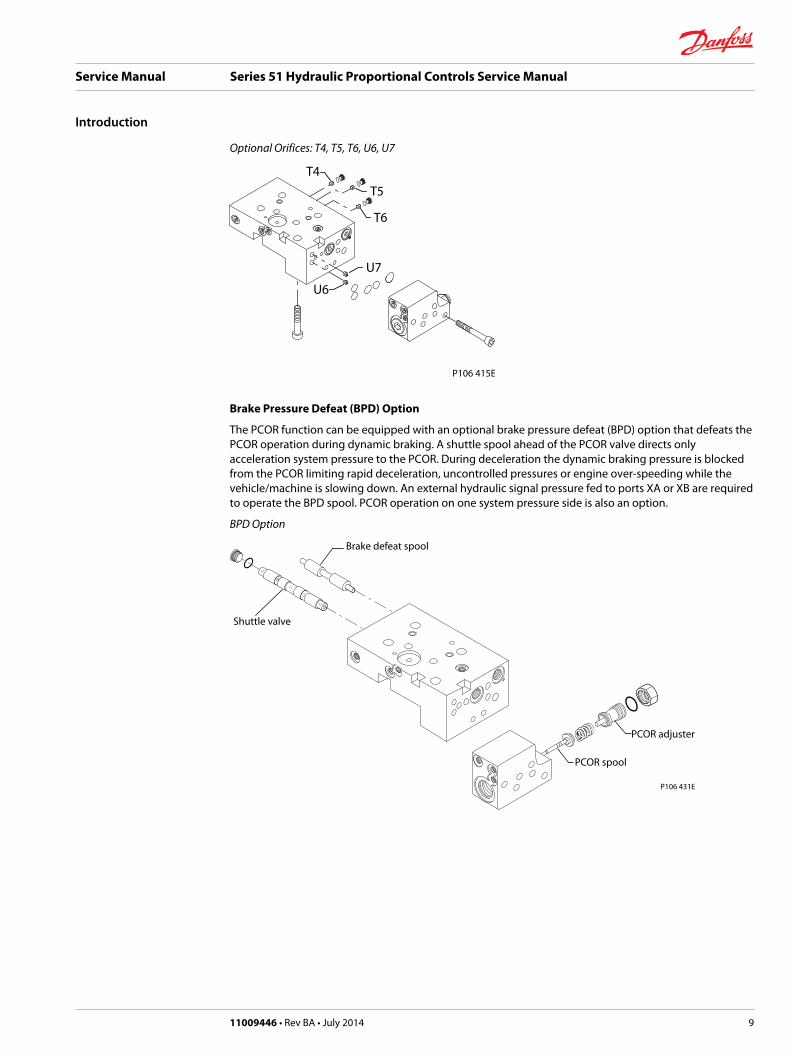
Optional Orifices: T4, T5, T6, U6, U7
T4
T6
T5
U7
U6
P106 415E
Brake Pressure Defeat (BPD) Option
The PCOR function can be equipped with an optional brake pressure defeat (BPD) option that defeats thePCOR operation during dynamic braking. A shuttle spool ahead of the PCOR valve directs onlyacceleration system pressure to the PCOR. During deceleration the dynamic braking pressure is blockedfrom the PCOR limiting rapid deceleration, uncontrolled pressures or engine over-speeding while thevehicle/machine is slowing down. An external hydraulic signal pressure fed to ports XA or XB are requiredto operate the BPD spool. PCOR operation on one system pressure side is also an option.
BPD Option
Shuttle valve
Brake defeat spool
PCOR spool
P106 431E
PCOR adjuster
Service Manual Series 51 Hydraulic Proportional Controls Service Manual
Introduction
11009446 • Rev BA • July 2014 9

Port locations and Gauge Installation
The following table and drawings show the port locations and gauge sizes needed. When testing systempressures, calibrate pressure gauges frequently to ensure accuracy. Use snubbers to protect gauges.
Port Information
Port identifier Port size Wrench size Reading Gauge size, bar [psi]
L1, L2 1 1/16-12 UNF 9/16 internal hex Case drain 10 bar [100 psi]
M1, M2 9/16-18 UNF 1/4 internal hex System pressure 600 bar [10,000 psi]
M3, M4, M5 9/16-18 UNF 1/4 internal hex Servo pressure 50 bar [1000 psi]
X1, M7 9/16-18 UNF 1/4 internal hex Control pressure 50 bar [1000 psi]
Port Locations
M2
M1
Thresholdadjustment
M3
M5
M1
M5
M3
A
L2
L1
M7
P106 434E
M4
M4
X1
M7X1
Radial ported motor
M3
M5
BA M
4
System port A
M1+M2
System port B
Axial ported motor
Service Manual Series 51 Hydraulic Proportional Controls Service Manual
Pressure measurements
10 11009446 • Rev BA • July 2014

Threshold Setting
Checking Threshold Setting
1. Install a 50 bar [600 psi] gauge at port M3 to read minimum servo pressure.
2. Install a 50 bar [600 psi] gauge at port M4 to read maximum servo pressure.
3. Install meter to read signal current.
4. Increase the signal current to the proper setting.
The pressure at port M3 should rise to about 100 psi [6.89 bar] higher than the pressure at port M4.This causes the servo piston to move toward minimum position. Signal current at this point is thethreshold setting.
On a test stand, increase signal current until the flow from the motor begins to decrease. The signalcurrent at this point is the threshold setting.
Adjusting Threshold Setting
1. Using a 10 mm wrench, loosen the locknut on the adjustment screw.
2. Using a 3 mm internal hex wrench turn the adjusting screw:• Clockwise (cw) to increase the setting
• Counterclockwise (ccw) to decrease the setting.
3. While holding the position of the adjustment screw:• tighten the locknut
• using a 10 mm wrench torque the locknut to 9 N•m [6.6 lbf•ft].
Service Manual Series 51 Hydraulic Proportional Controls Service Manual
Adjustments
11009446 • Rev BA • July 2014 11

Locknut and Threshold
Adjusting screw
Spring seat
P101 911
Locknut
10 mm 9 Nm [6.6 lbf•ft]
Pressure Compensator OverRide (PCOR) Setting
PCOR Adjustment
In order to measure and adjust the start pressure setting for the PCOR function:
1. Install a 600 bar [10000 psi] gauge at port M1 or M2 or M5 to read high system pressure.
2. Install a 600 bar [10000 psi] gauge at port M3 to read minimum servo pressure.
3. Lock the motor shaft from moving by:• Applying the park brake, apply an extreme load, or
• Position the machine against an immovable object, or
• Other means to hold the machine.
4. Start the prime mover. Operate at medium RPM.
Service Manual Series 51 Hydraulic Proportional Controls Service Manual
Adjustments
12 11009446 • Rev BA • July 2014

5. Stroke the pump very slowly to gradually increase the system pressure.
An alternate method to slowly increase the system pressure is to use the pump’s pressure limiter (PL)valve. Lower the PL setting below the PCOR setting. Stroke the pump to about one-fourthdisplacement. Raise the PL setting slowly to increase system pressure until pressure at the M3 portdrops down. System pressure at this point is the PCOR setting. Adjust the PL back to its proper settingafter checking the PCOR setting.
6. Increase system pressure until pressure at port M3 drops down, system pressure at this point is thePCOR setting.
Checking PCOR Setting on a Test Stand
Increase system pressure until the system flow begins to increase. System pressure at this point is thePCOR setting.
W Warning
System pressure may increase rapidly when flow increases.
Adjusting the PCOR Setting
• For PCOR valves mounted on a Multiblock; use a 1-1/16 inch wrench to loosen the lock nut on theadjusting screw. Using a large screw driver or a 13 mm wrench, turn the adjusting screw clockwise toincrease pressure setting or counter clockwise to lower pressure setting. One turn of the adjustingscrew changes the setting approximately 69 bar [1000 psi].
• For controls using the threshold adjusting screw for PCOR adjustment; use a 10 mm wrench to loosenthe locknut. Using a 3 mm wrench, turn the adjusting screw clockwise to increase pressure or counterclockwise to lower pressure setting. One turn of the adjusting screw changes the settingapproximately 55 bar [800 psi].
Service Manual Series 51 Hydraulic Proportional Controls Service Manual
Adjustments
11009446 • Rev BA • July 2014 13

Optional PCOR Housing
Disassembly
1. Remove plugs (N27). Remove and discard O-rings (N27A).
2. Using a 1 inch wrench, remove plug (N23). Remove and discard O-ring (N23A).
3. Remove locknut (N14).
4. Remove adjustment plug (Z00). Remove and discard O-ring (N16J).
5. Remove spring (N18).
6. Remove spool and spring guide assembly (N20).
7. Remove screws (N29).
8. Remove and discard O-rings (N24P, N82).
9. If present, remove orifices (U6, U7).
PCOR
N82
N29
N20 N14
N18
N16J
Z00N8 7
U6U7
N24P
P106 384E
N23
N27
N27
Legend
Item Wrench size Torque
N27 1/8 inch internal hex 7 Nm [4 lbf•ft]
N23 1 inch 40 Nm [30 lbf•ft]
U6, U7 3 mm internal hex 6 Nm [4 lbf•ft]
N29 5 mm internal hex 16 Nm [12 lbf•ft]
N14 1-5/16 inch N/A
Inspection
Clean and inspect components for damage or foreign material. Replace damaged parts.
Assembly
1. If previously removed, use a 3mm internal hex wrench to install orifices (U6, U7). Torque to 6 N•m [4lbf•ft].
2. Using petroleum jelly to retain them, install new interface O-rings (N24P, N82).
3. Position PCOR on multiblock. Install screws (N29). Torque using a 5 mm internal hex wrench to 16N•m [12 lbf•ft].
Service Manual Series 51 Hydraulic Proportional Controls Service Manual
PCOR
14 11009446 • Rev BA • July 2014

4. Lubricate and install spool and spring guide assembly (N20).
5. Install spring (N18) to cavity.
6. Lubricate and install new O-ring (N16J). Install adjustment plug (Z00).
7. Using a 1-1/16 inch hex wrench, install locknut (N14). Do not torque until after PCOR adjustment.Refer to page 13 for instructions.
8. Lubricate and install a new O-ring (N23A). Using a 1 inch hex wrench, install plug (N23). Torque to 40N•m [30 lbf•ft].
9. Lubricate and install new O-rings (N27A). Using a 1/8 inch internal hex wrench, install and torqueplugs (N27) to 7 N•m [4 lbf•ft].
Service Manual Series 51 Hydraulic Proportional Controls Service Manual
PCOR
11009446 • Rev BA • July 2014 15
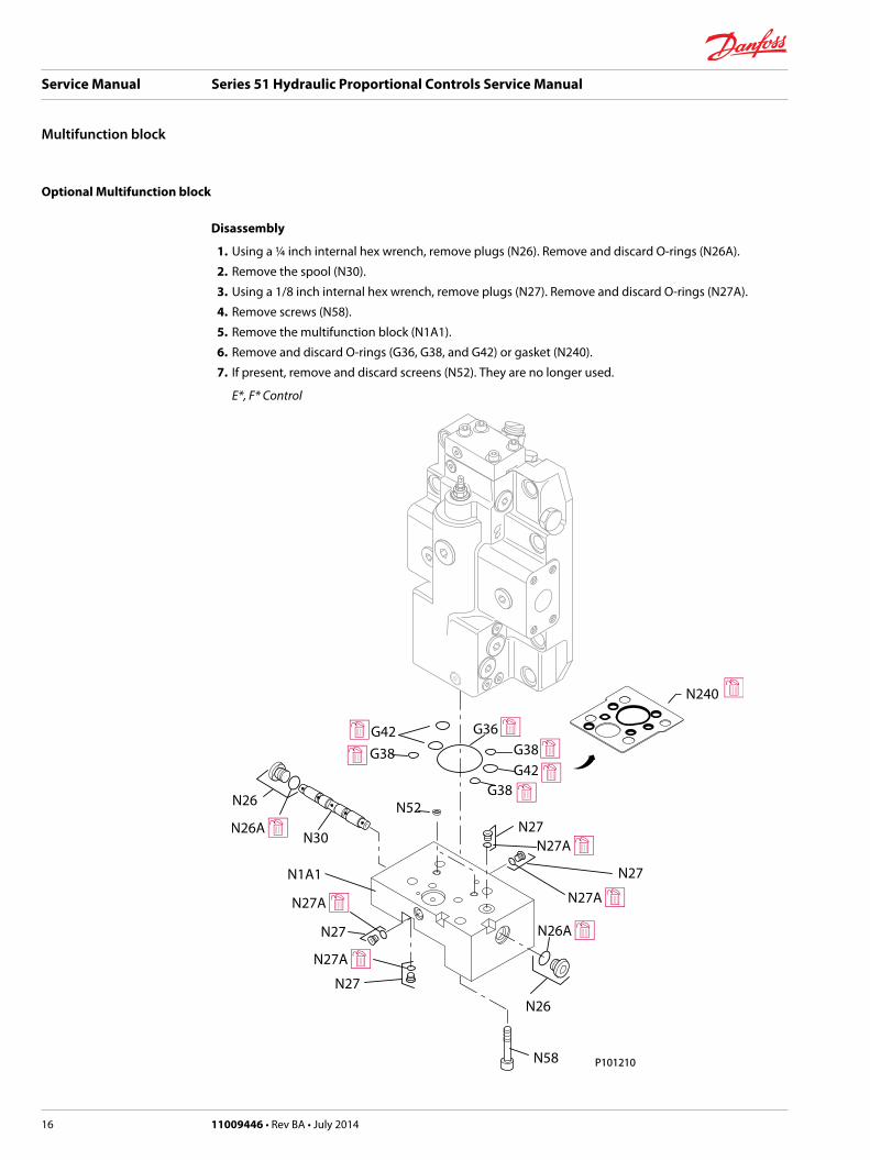
Optional Multifunction block
Disassembly
1. Using a ¼ inch internal hex wrench, remove plugs (N26). Remove and discard O-rings (N26A).
2. Remove the spool (N30).
3. Using a 1/8 inch internal hex wrench, remove plugs (N27). Remove and discard O-rings (N27A).
4. Remove screws (N58).
5. Remove the multifunction block (N1A1).
6. Remove and discard O-rings (G36, G38, and G42) or gasket (N240).
7. If present, remove and discard screens (N52). They are no longer used.
E*, F* Control
G42
G42G38
G38G38
G36
N52
N30
N1A1
N58 P101210
N27
N27
N27
N27
N26
N26
N240
Service Manual Series 51 Hydraulic Proportional Controls Service Manual
Multifunction block
16 11009446 • Rev BA • July 2014
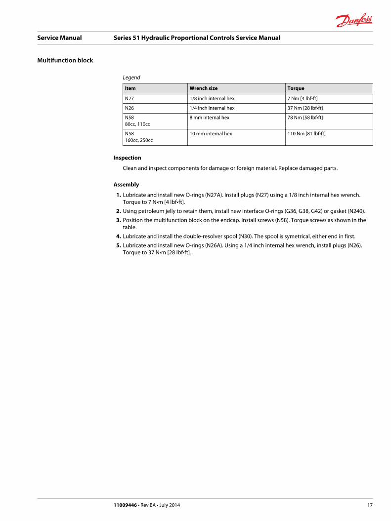
Legend
Item Wrench size Torque
N27 1/8 inch internal hex 7 Nm [4 lbf•ft]
N26 1/4 inch internal hex 37 Nm [28 lbf•ft]
N5880cc, 110cc
8 mm internal hex 78 Nm [58 lbf•ft]
N58160cc, 250cc
10 mm internal hex 110 Nm [81 lbf•ft]
Inspection
Clean and inspect components for damage or foreign material. Replace damaged parts.
Assembly
1. Lubricate and install new O-rings (N27A). Install plugs (N27) using a 1/8 inch internal hex wrench.Torque to 7 N•m [4 lbf•ft].
2. Using petroleum jelly to retain them, install new interface O-rings (G36, G38, G42) or gasket (N240).
3. Position the multifunction block on the endcap. Install screws (N58). Torque screws as shown in thetable.
4. Lubricate and install the double-resolver spool (N30). The spool is symetrical, either end in first.
5. Lubricate and install new O-rings (N26A). Using a 1/4 inch internal hex wrench, install plugs (N26).Torque to 37 N•m [28 lbf•ft].
Service Manual Series 51 Hydraulic Proportional Controls Service Manual
Multifunction block
11009446 • Rev BA • July 2014 17

Operation
Functional Description
The HZ, HA, HB, and HE controls consist of a ported housing mounted directly to the end cap. Variablesignal pressure fed to port X1 is routed to the end of the 4-way valve. A threshold spring and rampspring(s) act on the opposite end of the 4-way valve.
HZ Control
The HZ control has a check valve to resolve which port (system A or B) is higher pressure. It routes thishigh pressure to the 4-way valve to power the servo piston.
HA and HB Controls
The HA and HB controls have internal porting to feed system A or B pressures, respectively, to the 4-wayvalve to power the servo piston.
HE Control
The HE control has no internal porting for servo supply pressure. An external servo supply pressure fed toport M5 is required.
HZ Schematic Diagram
T2
T1
B
A
T7
max.disp.
L2
M4 M3
M2
M5
T8
T3
L1
M1
M7X1
P107 823
Service Manual Series 51 Hydraulic Proportional Controls Service Manual
HZ, HA, HB, HE Controls
18 11009446 • Rev BA • July 2014
Repair
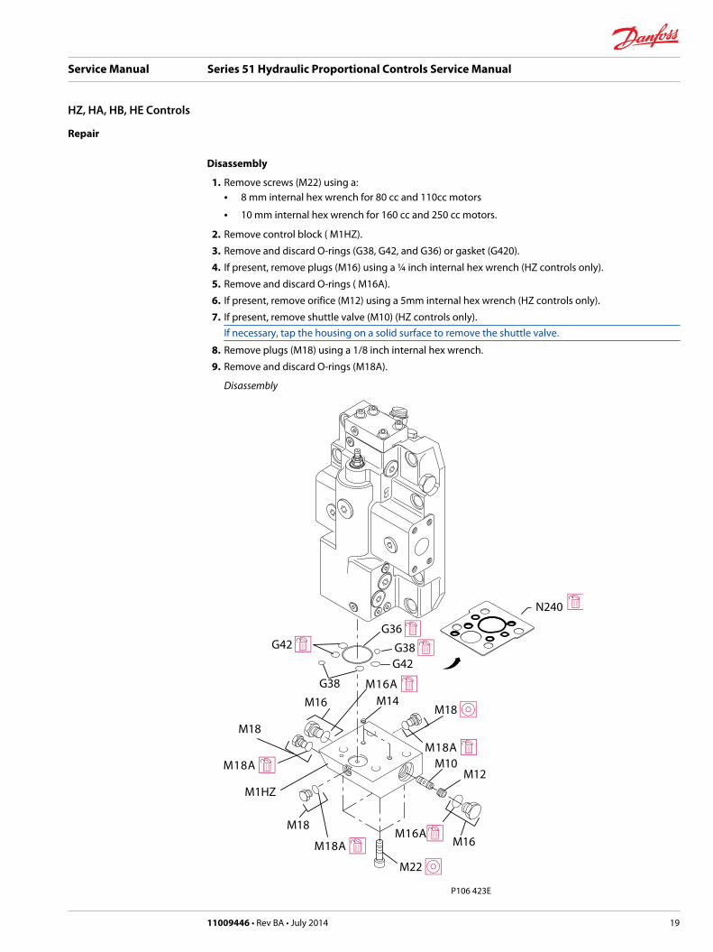
Disassembly
1. Remove screws (M22) using a:• 8 mm internal hex wrench for 80 cc and 110cc motors
• 10 mm internal hex wrench for 160 cc and 250 cc motors.
2. Remove control block ( M1HZ).
3. Remove and discard O-rings (G38, G42, and G36) or gasket (G420).
4. If present, remove plugs (M16) using a ¼ inch internal hex wrench (HZ controls only).
5. Remove and discard O-rings ( M16A).
6. If present, remove orifice (M12) using a 5mm internal hex wrench (HZ controls only).
7. If present, remove shuttle valve (M10) (HZ controls only).If necessary, tap the housing on a solid surface to remove the shuttle valve.
8. Remove plugs (M18) using a 1/8 inch internal hex wrench.
9. Remove and discard O-rings (M18A).
Disassembly
M1HZ
M18
M14
M12M10
P106 423E
N240
Service Manual Series 51 Hydraulic Proportional Controls Service Manual
HZ, HA, HB, HE Controls
11009446 • Rev BA • July 2014 19

Legend
Item Wrench size Torque
M18 1/8 internal hex 6 Nm [4 lbf•ft]
M12 5 mm internal hex 12 Nm [6 lbf•ft]
M16 1/4 internal hex 31 Nm [27 lbf•ft]
M22 (80, 110) 8 mm internal hex 78 Nm [58 lbf•ft]
M22 (160, 1250) 10 mm internal hex 110 Nm [81 lbf•ft]
Inspection
1. Inspect the housing and shuttle valve for damage or foreign material.
2. Check internal passages for contamination and clean them if necessary. If present, discard the 2screens ( M14) (they are no longer necessary).
Assembly
1. If used, install the shuttle valve assembly (M10) (HZ controls only).
2. If used, install orifice (M12) using a 5 mm internal hex wrench (HZ controls only). Torque to 8 N•m [6lbf•ft].
C Caution
Overtorquing orifice (M12) may crush shuttle valve (M10).
3. Lubricate and Install new O-rings to all plugs.
4. Using a 1/4 inch internal hex wrench, install plugs (M16). Torque to 37 N•m [27 lbf•ft].
5. Using a 1/8 inch internal hex wrench, install plugs (M18). Torque to 6 N•m [4 lbf•ft].
6. Using petroleum jelly to retain them, install new O-rings (G36, G38, G42) or install gasket (G420).
7. Install the control housing onto the end cap.
8. Install screws (M22). Torque screws to:• 78 N•m [58 lbf•ft] for 80 cc, and 110cc motors using an 8mm internal hex wrench.
• 110 N•m [81 lbf•ft] for 160cc and 250cc motors using a 10 mm internal hex wrench.
Service Manual Series 51 Hydraulic Proportional Controls Service Manual
HZ, HA, HB, HE Controls
20 11009446 • Rev BA • July 2014

Operation
Functional Description
The HS control consists of a ported housing mounted on a multiblock. External variable signal pressurefed to port X1 is routed to the 4-way valve. As signal pressure shifts the 4-way valve it ports pressure tothe ends of the servo piston changing motor displacement. A threshold spring and ramp spring(s) act onthe opposite end of the 4-way valve.
HS Schematic
n
T6T2
T1 T7 T8
T3
T4
U6U7
T5
max.disp.
AL2 M4 M3 N
M1
L1
M2
M7 X1
M5
XA XB B
P106 417E
Control
MultiblockPCOR Valve
BPD SpoolShuttle
Loop Flush
4-Way Valve
Repair
Disassembly
1. Using a 4 mm internal hex wrench, remove screws (M10).
2. Remove the HS valve housing from the multifunction block.
3. Remove and discard O-ring (M12).
Service Manual Series 51 Hydraulic Proportional Controls Service Manual
HS Control
11009446 • Rev BA • July 2014 21

Disassembly
E101 489E
M10
M17
M17A
M12
4. Remove plug (M17) using a 1/4 internal hex wrench.
5. Remove and discard O-ring (M17A).
Inspection
1. Inspect the housings for damage or foreign material.
2. Check internal passages for contamination. Clean passages if necessary.
Assembly
1. Using petroleum jelly to retain it, install a new O-ring (M12).
2. Install the HS valve housing on to the multifunction block.
3. Using a 4 mm internal hex, install screws (M10). Torque to 6.4 Nm [4.7 lbf•ft].
4. Lubricate and install a new O-ring (M17A).
5. Using a 1/4 internal hex wrench install plug (M17). Torque to 37 N•m [28 lbf•ft].
Refer to Optional Multifunction block on page 16 for multiblock repair.
Service Manual Series 51 Hydraulic Proportional Controls Service Manual
HS Control
22 11009446 • Rev BA • July 2014

Operation
Functional Description
The H1, H2, K1, and K2 controls consist of a ported housing mounted on the multiblock. It contains asolenoid valve and internal porting to direct the external variable signal pressure through the solenoidvalve to the end of the 4-way valve. A threshold spring and ramp spring(s) act on the opposite end of the4-way valve.
Solenoid Valve
The solenoid valve (M1) is a 2-position 3-way valve that passes the external signal pressure to the end ofthe 4-way valve, or blocks the external signal and drains the end of the 4-way valve to the motor case.The H1 and K1 solenoid valves have a 12-volt coil with DIN connector. The H2 and K2 solenoid valveshave a 24-volt coil with DIN connector. The 4-way valve and the solenoid valve are the same for H1, H2,K1, and K2 controls. The control housings are different between the H1, H2, and the K1, K2 controls. Thelogic for the control is:• If H1 or H2 are energized operation is proportional; if de-energized output is maximum displacement.
• If K1 or K2 are energized, output is maximum displacement; if de-energized, operation isproportional.
Refer to Multiblock on page 8 Pressure Compensator OverRide (PCOR) Function on page 8 and BrakePressure Defeat (BPD) Option on page 9 for multiblock, PCOR and brake pressure defeat information.
H1, H2 Schematic
P107 825
T2
T1
B
A
T7
max.disp.
L2
M4 M3
M2
M3 (M5)
T8
T3
L1
M1
X1M7
T6
T4
U6U7
T5
XA XB
Multiblock
PCOR Valve
BPD Spool ShuttleLoop Flush
4-Way Valve
Repair
The solenoid valve (M1) is available as a complete assembly only. Do not remove unless it is beingreplaced.
Service Manual Series 51 Hydraulic Proportional Controls Service Manual
H1, H2, K1, K2 Controls
11009446 • Rev BA • July 2014 23
Removing Solenoid Valve
1. Using a 3/4 wrench, remove the coil nut from the solenoid cartridge valve (M1).
2. Remove the coil from the solenoid cartridge valve (M1). Using a 7/8 wrench, remove the solenoidcartridge valve (M1) from the control housing.
Disassembly
1. Using a 1/4 internal hex wrench, remove plugs (M22, M18) (and M24 if present).
2. Remove and discard O-rings (M22A, M18A, and M24A).
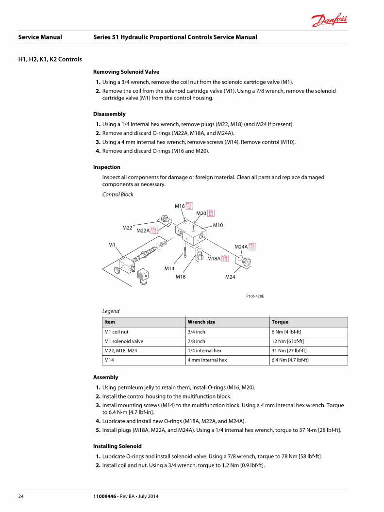
3. Using a 4 mm internal hex wrench, remove screws (M14). Remove control (M10).
4. Remove and discard O-rings (M16 and M20).
Inspection
Inspect all components for damage or foreign material. Clean all parts and replace damagedcomponents as necessary.
Control Block
P106 428E
Legend
Item Wrench size Torque
M1 coil nut 3/4 inch 6 Nm [4 lbf•ft]
M1 solenoid valve 7/8 inch 12 Nm [6 lbf•ft]
M22, M18, M24 1/4 internal hex 31 Nm [27 lbf•ft]
M14 4 mm internal hex 6.4 Nm [4.7 lbf•ft]
Assembly
1. Using petroleum jelly to retain them, install O-rings (M16, M20).
2. Install the control housing to the multifunction block.
3. Install mounting screws (M14) to the multifunction block. Using a 4 mm internal hex wrench. Torqueto 6.4 N•m [4.7 lbf•in].
4. Lubricate and install new O-rings (M18A, M22A, and M24A).
5. Install plugs (M18A, M22A, and M24A). Using a 1/4 internal hex wrench, torque to 37 N•m [28 lbf•ft].
Installing Solenoid
1. Lubricate O-rings and install solenoid valve. Using a 7/8 wrench, torque to 78 Nm [58 lbf•ft].
2. Install coil and nut. Using a 3/4 wrench, torque to 1.2 Nm [0.9 lbf•ft].
Service Manual Series 51 Hydraulic Proportional Controls Service Manual
H1, H2, K1, K2 Controls
24 11009446 • Rev BA • July 2014
Operation
Functional Description
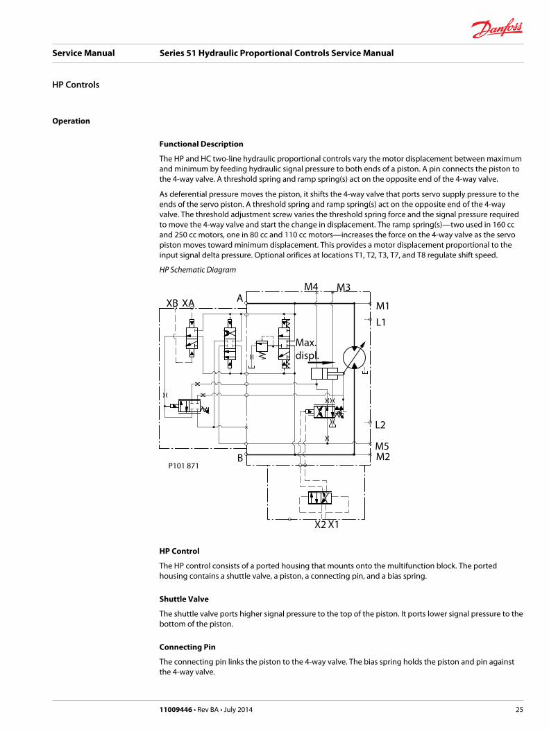
The HP and HC two-line hydraulic proportional controls vary the motor displacement between maximumand minimum by feeding hydraulic signal pressure to both ends of a piston. A pin connects the piston tothe 4-way valve. A threshold spring and ramp spring(s) act on the opposite end of the 4-way valve.
As deferential pressure moves the piston, it shifts the 4-way valve that ports servo supply pressure to theends of the servo piston. A threshold spring and ramp spring(s) act on the opposite end of the 4-wayvalve. The threshold adjustment screw varies the threshold spring force and the signal pressure requiredto move the 4-way valve and start the change in displacement. The ramp spring(s)—two used in 160 ccand 250 cc motors, one in 80 cc and 110 cc motors—increases the force on the 4-way valve as the servopiston moves toward minimum displacement. This provides a motor displacement proportional to theinput signal delta pressure. Optional orifices at locations T1, T2, T3, T7, and T8 regulate shift speed.
HP Schematic Diagram
M4 M3
M1
L1
L2
M5M2B
XB XA A
Max.displ.
X2 X1
P101 871
HP Control
The HP control consists of a ported housing that mounts onto the multifunction block. The portedhousing contains a shuttle valve, a piston, a connecting pin, and a bias spring.
Shuttle Valve
The shuttle valve ports higher signal pressure to the top of the piston. It ports lower signal pressure to thebottom of the piston.
Connecting Pin
The connecting pin links the piston to the 4-way valve. The bias spring holds the piston and pin againstthe 4-way valve.
Service Manual Series 51 Hydraulic Proportional Controls Service Manual
HP Controls
11009446 • Rev BA • July 2014 25
Repair
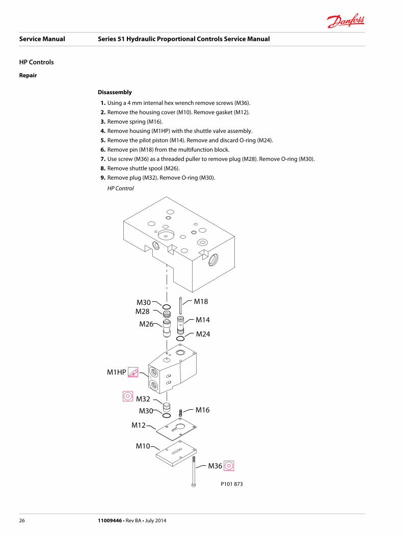
Disassembly
1. Using a 4 mm internal hex wrench remove screws (M36).
2. Remove the housing cover (M10). Remove gasket (M12).
3. Remove spring (M16).
4. Remove housing (M1HP) with the shuttle valve assembly.
5. Remove the pilot piston (M14). Remove and discard O-ring (M24).
6. Remove pin (M18) from the multifunction block.
7. Use screw (M36) as a threaded puller to remove plug (M28). Remove O-ring (M30).
8. Remove shuttle spool (M26).
9. Remove plug (M32). Remove O-ring (M30).
HP Control
P101 873
M26
M10
M30
M30 M18
M14
M24
M16
M12
Service Manual Series 51 Hydraulic Proportional Controls Service Manual
HP Controls
26 11009446 • Rev BA • July 2014
Legend
Item Wrench size Torque
M36 4 mm internal hex 6.4 Nm [4.7 lbf•ft]
Inspection
1. Clean and inspect all parts.
2. Discard any parts that are worn or damaged.
Assembly
1. Install new O-rings (M30).
2. Install new O-ring (M24).
3. Install plug (M32) with the large chamfer toward the inside of the block.
4. Install shuttle spool (M26).
5. Install plug (M28) with the large chamfer toward the inside of the block.
6. Install pin (M18) in the multiblock.
7. Position the control valve housing on the multifunction block.
8. Install the pilot piston (M14) into the control valve housing over pin (M18).
9. Install spring (M16).
10. Install new gasket (M12).
11. Install control cover (M10).
12. Position control assembly (M1HP) on multifunction block to align the screw holes.
13. Using a 4 mm internal hex wrench, install screws (M36). Torque to 6.4 Nm [4.7 lbf•ft].
Service Manual Series 51 Hydraulic Proportional Controls Service Manual
HP Controls
11009446 • Rev BA • July 2014 27
Operation
Functional Description
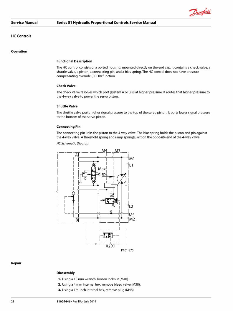
The HC control consists of a ported housing, mounted directly on the end cap. It contains a check valve, ashuttle valve, a piston, a connecting pin, and a bias spring. The HC control does not have pressurecompensating override (PCOR) function.
Check Valve
The check valve resolves which port (system A or B) is at higher pressure. It routes that higher pressure tothe 4-way valve to power the servo piston.
Shuttle Valve
The shuttle valve ports higher signal pressure to the top of the servo piston. It ports lower signal pressureto the bottom of the servo piston.
Connecting Pin
The connecting pin links the piston to the 4-way valve. The bias spring holds the piston and pin againstthe 4-way valve. A threshold spring and ramp spring(s) act on the opposite end of the 4-way valve.
HC Schematic Diagram
M4 M3
M1
L1
L2
M5M2B
Max.displ.
X2 X1
A
P101 875
Repair
Diassembly
1. Using a 10 mm wrench, loosen locknut (M40).
2. Using a 4 mm internal hex, remove bleed valve (M38).
3. Using a 1/4-inch internal hex, remove plug (M48)
Service Manual Series 51 Hydraulic Proportional Controls Service Manual
HC Controls
28 11009446 • Rev BA • July 2014
4. Remove and discard O-ring (M48A).
5. Remove check ball seat (M46) using a 5 mm internal hex.
6. Remove check ball (M47) using a pencil magnet.
7. Using a 1/4-inch internal hex, remove plugs (M34).
8. Remove and discard O-rings (M34A).
9. Slide shuttle spool (M44) out of block.
10. Using a 10 mm wrench, loosen locknut (M16). Using a 4 mm internal hex, remove adjustment screw(M18).
11. Remove screws (M28).
12. Remove cover (M12). Remove gasket (M14).
13. Remove spring seat (M20). Remove spring (M22).
14. Remove the pilot piston (M24).
15. Remove spring seat (M25). Remove pin (M26).
16. Remove spring (J10).
17. Remove screws (M10) and washers (M11).
18. Remove block (M1HC).
19. Remove and discard O-rings (G38), (G36) and (G42) or gasket (N240).
20. Remove 4-way valve (F32).
21. Remove and discard O-rings (F324).
Inspection
1. Inspect the control block for signs of corrosion or damage.
2. Discard any damaged or worn parts.
Service Manual Series 51 Hydraulic Proportional Controls Service Manual
HC Controls
11009446 • Rev BA • July 2014 29
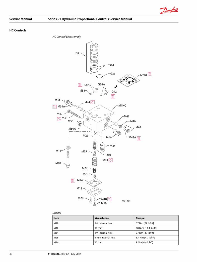
HC Control Disassembly
J10
M26
M11
M47
M46
M34
M38
M40
M50A
M50
F32
F324
G38
G42 G38
G42
M48A
M48
M34A
M34
M34
M10
M25
M22
M20
M14
M12
M16P101 882
G36
M1HC
M28
N240
Legend
Item Wrench size Torque
M48 1/4 internal hex 37 Nm [27 lbf•ft]
M40 10 mm 18 N•m [13.3 lbf•ft]
M34 1/4 internal hex 37 Nm [27 lbf•ft]
M28 4 mm internal hex 6.4 Nm [4.7 lbf•ft]
M16 10 mm 9 Nm [6.6 lbf•ft]
Service Manual Series 51 Hydraulic Proportional Controls Service Manual
HC Controls
30 11009446 • Rev BA • July 2014
Legend (continued)
Item Wrench size Torque
M18 4 mm internal hex N/A
M10 (060, 080, 110) 8 mm internal hex 78 Nm [58 lbf•ft]
M10 (160, 250) 10 mm internal hex 110 Nm [81 lbf•ft]
Assembly
1. Lubricate and install O-rings (F324).
2. Install 4-way valve (F32).
3. Using petroleum jelly, lubricate and install O-rings (G38), (G36) and (G42) or install gasket (N240).
4. Install block (M1HC).
5. Install screws (M10) and washers (M11), if present.
6. Install spring (J10).
7. Install pin (M26). Install spring seat (M25).
8. Install the pilot piston (M24).
9. Install spring (M22). Install spring seat (M20)
10. Install gasket (M14). Install cover (M12).
11. Using a 4 mm internal hex wrench, install screws (M28). Torque to 6.4 Nm [4.7 lbf•ft].
12. Install adjustment screw (M18). Install locknut (M16).
13. Hold adjustment screw in place and torque locknut (M16) to 9 Nm [6.6 lbf•ft].
14. Slide shuttle spool (M44) into block.
15. Lubricate and install O-rings (M34A).
16. Using a 1/4-inch internal hex, install plugs (M34).
17. Install check ball (M47)
18. Install check ball seat (M46)
19. Lubricate and install O-ring (M48A).
20. Using a 1/4-inch internal hex, install plug (M48)
21. Using a 4 mm internal hex, install bleed valve (M38).
22. Using a 10 mm wrench, install locknut (M40).
23. Hold bleed valve in place and torque lock nut per table.
Service Manual Series 51 Hydraulic Proportional Controls Service Manual
HC Controls
11009446 • Rev BA • July 2014 31
Operation
Functional Description
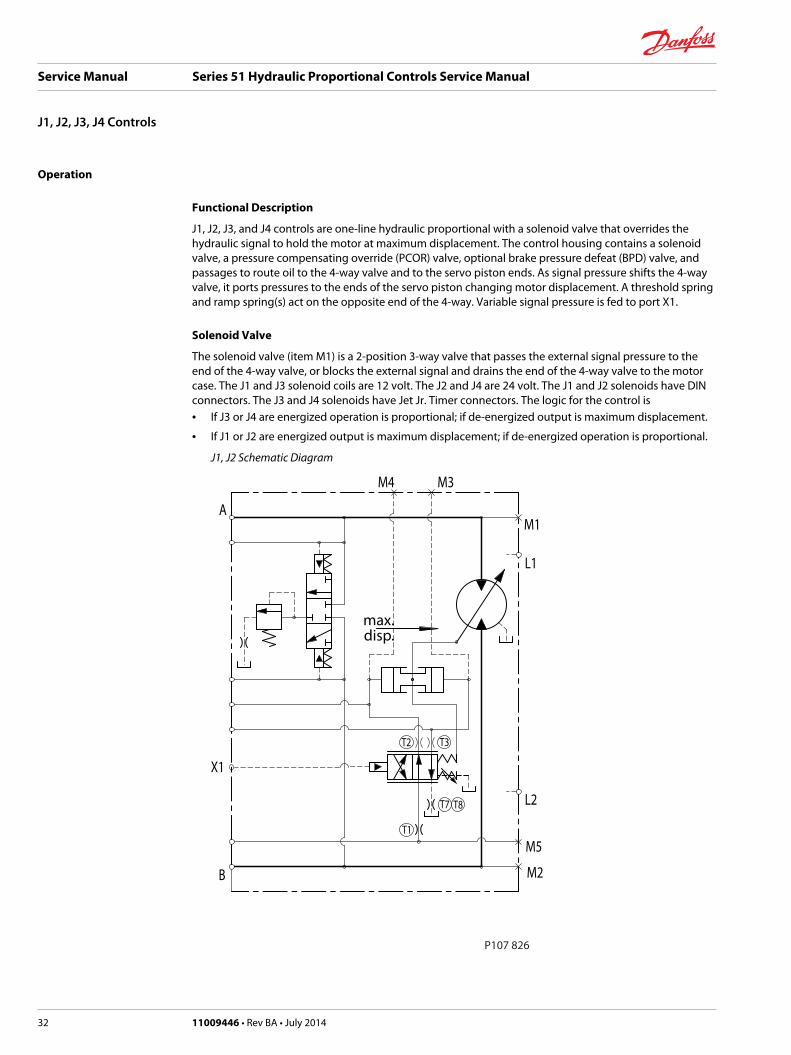
J1, J2, J3, and J4 controls are one-line hydraulic proportional with a solenoid valve that overrides thehydraulic signal to hold the motor at maximum displacement. The control housing contains a solenoidvalve, a pressure compensating override (PCOR) valve, optional brake pressure defeat (BPD) valve, andpassages to route oil to the 4-way valve and to the servo piston ends. As signal pressure shifts the 4-wayvalve, it ports pressures to the ends of the servo piston changing motor displacement. A threshold springand ramp spring(s) act on the opposite end of the 4-way. Variable signal pressure is fed to port X1.
Solenoid Valve
The solenoid valve (item M1) is a 2-position 3-way valve that passes the external signal pressure to theend of the 4-way valve, or blocks the external signal and drains the end of the 4-way valve to the motorcase. The J1 and J3 solenoid coils are 12 volt. The J2 and J4 are 24 volt. The J1 and J2 solenoids have DINconnectors. The J3 and J4 solenoids have Jet Jr. Timer connectors. The logic for the control is• If J3 or J4 are energized operation is proportional; if de-energized output is maximum displacement.
• If J1 or J2 are energized output is maximum displacement; if de-energized operation is proportional.
J1, J2 Schematic Diagram
T2
T1
B
A
T7
max.disp.
L2
M4 M3
M2
M5
T8
T3
L1
M1
P107 826
X1
Service Manual Series 51 Hydraulic Proportional Controls Service Manual
J1, J2, J3, J4 Controls
32 11009446 • Rev BA • July 2014
Repair
Removing the Solenoid Valve
It is not necessary to remove the valve unless it is being replaced.
Individual parts are not available. Replace entire valve.
Solenoid for J1, J2
If replacing the valve, use a 7/8 wrench to remove the valve from the housing.
Solenoid for J3, J4
If replacing the valve, use a 3 mm internal hex wrench to remove screws (M15). Remove the valve.
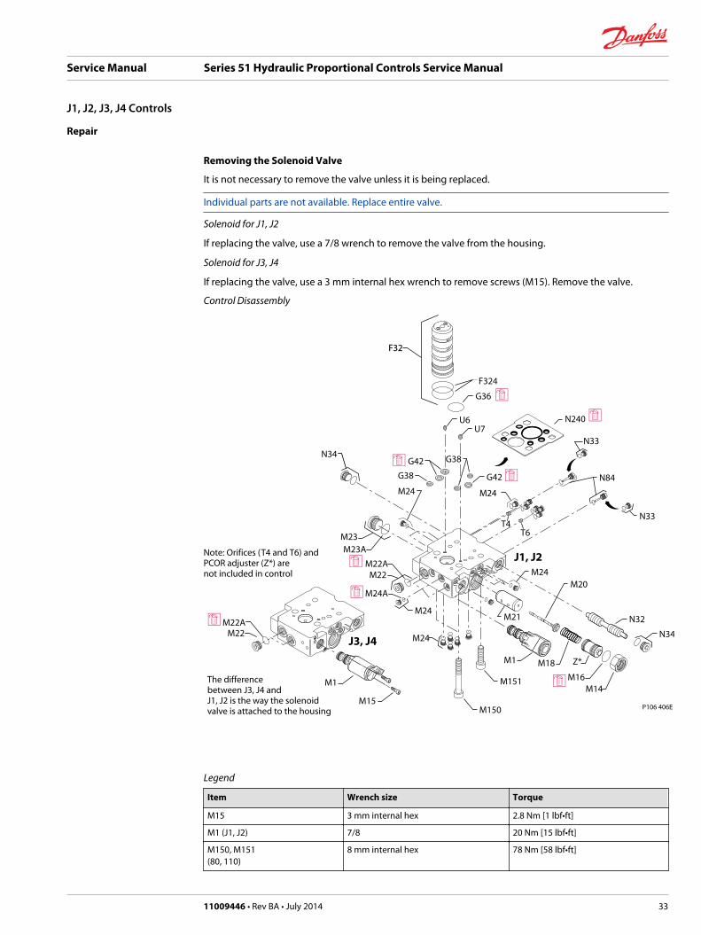
Control Disassembly
F32
F324
M24
T6T4
M23M23A
M24
U7
N84
M21
M18
M16M14
M20
N34
N33
N33
N34
M22
M24
M24A
M22A
M24
M24
U6
M151
M150
M1 Z*
G38
G42 G38
G42
G36
N32
M22M22A
M15
M1
Note: Orifices (T4 and T6) and PCOR adjuster (Z*) arenot included in control
J1, J2
J3, J4
The differencebetween J3, J4 and J1, J2 is the way the solenoidvalve is attached to the housing P106 406E
N240
Legend
Item Wrench size Torque
M15 3 mm internal hex 2.8 Nm [1 lbf•ft]
M1 (J1, J2) 7/8 20 Nm [15 lbf•ft]
M150, M151(80, 110)
8 mm internal hex 78 Nm [58 lbf•ft]
Service Manual Series 51 Hydraulic Proportional Controls Service Manual
J1, J2, J3, J4 Controls
11009446 • Rev BA • July 2014 33

Legend (continued)
Item Wrench size Torque
M150, M151(160, 1250)
10 mm internal hex 110 Nm [81 lbf•ft]
Item Wrench size Torque
M14 1 1/16 54 Nm [40 lbf•ft]
T4, T5, U6, U7 3 mm internal hex 3.7 Nm [2.7 lbf•ft]
N34, M22 1/4 internal hex 37 Nm [27 lbf•ft]
M23 3/8 internal hex 95 Nm [70 lbf•ft]
M24 1/8 internal hex 6 Nm [4.5 lbf•ft]
N84, N33 7/16 internal hex 12 Nm [9 lbf•ft]
Disassembly
1. Remove PCOR lock nut (M14).
2. Remove and discard O-ring (M16).
3. Remove the adjuster (Z*).
4. Remove the spring (M18).
5. Remove the PCOR spool assembly (M20).
C Caution
Do not remove the PCOR valve bushing (M21).
6. Using a 7/16 wrench, remove the pin/plugs (N84) or (N33).
7. Remove and discard the O-rings (N84A) or (N33A).
8. Using a 1/8 internal hex wrench, remove 15 plugs (M24).
9. Remove and discard O-rings (M24A).
10. Using a 1/4 internal hex wrench, remove plugs (M22, N34).
11. Remove and discard O-rings (M22A, N34A).
12. Remove spool (N32).
13. Using a 3/8 internal hex, remove plug (M23). Discard O-rings (M23A).
14. Remove screws (M150 and M151) using a:• 8mm internal hex wrench for 80 cc and 110cc motors
• 10 mm internal hex wrench for 160cc and 250cc motors
15. Remove the control assembly from the end cap.
16. Remove the 4-way valve assembly (F32).
C Caution
Read Series 51 and 51-1 Bent Axis Motors Service Manual 11008567 for minor repair instructions for the4-way valve, threshold spring, and ramp spring components, if repair is necessary.
17. Remove and discard O-rings (F324).
18. Remove and discard O-rings (G38), (G36) and (G42) or the gasket (N240).
19. Using a 3 mm internal hex, remove orifices (T4, T6, U6, U7).
Inspection
1. Inspect the housing for signs of corrosion or damage.
2. Discard any damaged parts.
Service Manual Series 51 Hydraulic Proportional Controls Service Manual
J1, J2, J3, J4 Controls
34 11009446 • Rev BA • July 2014

Assembly
1. Using a 3mm internal hex, install orifices (T4, T5, U6, U7). Torque to 3.7 Nm [2.7 lbf•ft].
2. Lubricate and install O-rings (F324).
3. Install the 4-way valve assembly (F32).
4. Using petroleum jelly, lubricate and install a new O-rings (G38, G36 and G42) or install gasket (N240).
5. Install the control assembly to the end cap.
6. Install screws (M150 and M151).
7. Torque screws (M150 and M151) to:• 78 N•m [58 lbf•ft]. Use an 8mm internal hex wrench for 80 cc and 110cc motors.
• 110 N•m [81 lbf•ft]. Use a 10 mm internal hex for 160cc and 250ccmotors.
8. Install spool (N32).
9. Lubricate and install O-rings (N34A and M22). Using a 1/4 internal hex wrench, install plugs (M22 andN34). Torque to 25 Nm [18 lbf•in].
10. Lubricate O-ring (M23A). Using a 3/8 internal hex wrench, install plug (M23). Torque to 95 Nm [70lbf•in].
11. Lubricate and install 15 O-rings (M24A). Using an 1/8 internal hex wrench, install 15 plugs M24).Torque to 6 Nm [4 lbf•in].
12. Lubricate and install O-rings (N84A) or (N33A). Using a 7/16 wrench, install plugs (N84) or (N33).Torque to 12 Nm [9 lbf•in].
13. Install the PCOR spool assembly (M20).
14. Install spring (M18). Install adjuster (Z*).
15. Lubricate and install O-ring (M16).
16. Install lock nut (M14). Torque to 54 Nm [40 lbf•in].
C Caution
Readjust the PCOR to its proper setting
Installing the Solenoid Valve
Solenoid for J1, J2
Lubricate O-rings. Use a 7/8 wrench to install the valve. Torque to 20 Nm [15 lbf•ft].
Solenoid for J3, J4
Use a 3 mm internal hex wrench to install screws (M15). Torque to 2.8 Nm [2.1 lbf•ft].
Service Manual Series 51 Hydraulic Proportional Controls Service Manual
J1, J2, J3, J4 Controls
11009446 • Rev BA • July 2014 35
Operation
Functional Description
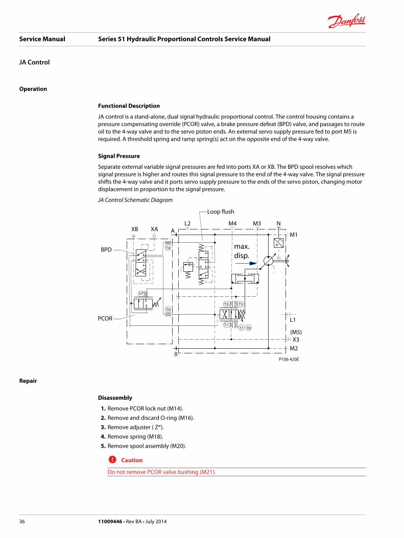
JA control is a stand-alone, dual signal hydraulic proportional control. The control housing contains apressure compensating override (PCOR) valve, a brake pressure defeat (BPD) valve, and passages to routeoil to the 4-way valve and to the servo piston ends. An external servo supply pressure fed to port M5 isrequired. A threshold spring and ramp spring(s) act on the opposite end of the 4-way valve.
Signal Pressure
Separate external variable signal pressures are fed into ports XA or XB. The BPD spool resolves whichsignal pressure is higher and routes this signal pressure to the end of the 4-way valve. The signal pressureshifts the 4-way valve and it ports servo supply pressure to the ends of the servo piston, changing motordisplacement in proportion to the signal pressure.
JA Control Schematic Diagram
n
T2 T3
T7 T8T1
T6
T4 max.disp.
B
XB XA AL2 M4 M3 N
M1
L1
M2
(M5)X3
P106 420E
U7
Loop flush
PCOR
BPD
Repair
Disassembly
1. Remove PCOR lock nut (M14).
2. Remove and discard O-ring (M16).
3. Remove adjuster ( Z*).
4. Remove spring (M18).
5. Remove spool assembly (M20).
C Caution
Do not remove PCOR valve bushing (M21).
Service Manual Series 51 Hydraulic Proportional Controls Service Manual
JA Control
36 11009446 • Rev BA • July 2014

Control Disassembly
E101 480EJA
M24
T6T4
M23
M23A
M24
U7M84
M21
M18
M16M14
M20
M24
M24A
M24
M24
Z*
G38
G42 G38
G42
M32
M84A
N240
Legend
Item Wrench size Torque
M150, M151(80, 110)
8 mm internal hex 78 Nm [58 lbf•ft]
M150, M151(160, 1250)
10 mm internal hex 110 Nm [81 lbf•ft]
M14 1 1/16 54 Nm [40 lbf•ft]
Item Wrench size Torque
T4, T6, U7 3 mm internal hex 3.7 Nm [2.7 lbf•ft]
M23 3/8 internal hex 25 Nm [18 lbf•ft]
M24 1/8 internal hex 6 Nm [4.5 lbf•ft]
M84 7/16 internal hex 12 Nm [9 lbf•ft]
Service Manual Series 51 Hydraulic Proportional Controls Service Manual
JA Control
11009446 • Rev BA • July 2014 37

6. Using a 7/16 wrench remove pin/plugs (M84).
7. Remove and discard O-rings (M84A).
8. Remove spool (M32).
9. Using a 1/8 internal hex wrench remove 13 plugs (M24).
10. Remove and discard O-rings (M24A).
11. Using a 3/8 internal hex wrench remove plug (M23).
12. Remove and discard O-ring (M23A).
13. Remove screws (M150 and M151) using a:• 8mm internal hex wrench for the 80 cc and 110cc motors
• 10 mm internal hex wrench for the 160cc and 250cc motors.
14. Remove the control from the endcap.
15. Remove 4-way valve assembly (F32).
C Caution
If repair is necessary to the 4-way valve, threshold spring, and ramp spring components, refer to Series51 and Series 51-1 Motors Service Manual 11008567.
16. Remove and discard O-rings (F324).
17. Remove O-rings (G38), (G36) and (G42) or gasket (N240).
18. Using a 3 mm internal hex, remove orifices (T4, T6, U7).
Inspection
1. Inspect the housing (M1) for signs of corrosion or damage.
2. Replace any damaged parts.
Assembly
1. Using a 3 mm internal hex, install orifices (T4, T6, U7). Torque to 3.7 Nm [2.7 lbf•ft].
2. Lubricate and install O-rings (F324).
3. Install the 4-way valve assembly (F32).
4. Using petroleum jelly, lubricate and install a new O-rings (G38, G36 and G42) or install gasket (N240).
5. Install the control assembly to the end cap.
6. Install screws (M150 and M151).
7. Torque screws (M150 and M151) to:• 78 N•m [58 lbf•ft]. Use an 8mm internal hex wrench for 80 cc and 110cc motors.
• 110 N•m [81 lbf•ft]. Use a 10 mm internal hex for 160cc and 250ccmotors.
8. Install spool (M32).
9. Lubricate O-ring (M23A). Using a 3/8 internal hex wrench, install plug (M23). Torque to 25 Nm [18lbf•in].
10. Lubricate and install 13 O-rings (M24A). Using an 1/8 internal hex wrench, install 13 plugs M24).Torque to 6 Nm [4 lbf•in].
11. Lubricate and install O-rings (M84A). Using a 7/16 wrench, install plugs (M84). Torque to 12 Nm [9lbf•in].
12. Install the PCOR spool assembly (M20).
13. Install spring (M18). Install adjuster (Z*).
14. Lubricate and install O-ring (M16).
15. Install lock nut (M14). Torque to 54 Nm [40 lbf•in].
Service Manual Series 51 Hydraulic Proportional Controls Service Manual
JA Control
38 11009446 • Rev BA • July 2014

C Caution
Readjust the PCOR to its proper setting
Service Manual Series 51 Hydraulic Proportional Controls Service Manual
JA Control
11009446 • Rev BA • July 2014 39
Danfoss Power Solutions is a global manufacturer and supplier of high-quality hydraulic andelectronic components. We specialize in providing state-of-the-art technology and solutionsthat excel in the harsh operating conditions of the mobile off-highway market. Building onour extensive applications expertise, we work closely with our customers to ensureexceptional performance for a broad range of off-highway vehicles.
We help OEMs around the world speed up system development, reduce costs and bringvehicles to market faster.
Danfoss – Your Strongest Partner in Mobile Hydraulics.
Go to www.powersolutions.danfoss.com for further product information.
Wherever off-highway vehicles are at work, so is Danfoss. We offer expert worldwide supportfor our customers, ensuring the best possible solutions for outstanding performance. Andwith an extensive network of Global Service Partners, we also provide comprehensive globalservice for all of our components.
Please contact the Danfoss Power Solution representative nearest you.
Local address:
Danfoss Power Solutions GmbH & Co. OHGKrokamp 35D-24539 Neumünster, GermanyPhone: +49 4321 871 0
Danfoss Power Solutions ApSNordborgvej 81DK-6430 Nordborg, DenmarkPhone: +45 7488 2222
Danfoss Power Solutions US Company2800 East 13th StreetAmes, IA 50010, USAPhone: +1 515 239 6000
Danfoss Power Solutions(Shanghai) Co., Ltd.Building #22, No. 1000 Jin Hai RdJin Qiao, Pudong New DistrictShanghai, China 201206Phone: +86 21 3418 5200
Danfoss can accept no responsibility for possible errors in catalogues, brochures and other printed material. Danfoss reserves the right to alter its products without notice. This also applies toproducts already on order provided that such alterations can be made without changes being necessary in specifications already agreed..All trademarks in this material are property of the respective companies. Danfoss and the Danfoss logotype are trademarks of Danfoss A/S. All rights reserved.
11009446 • Rev BA • July 2014 www.danfoss.com © Danfoss A/S, 2014
Products we offer:
• Bent Axis Motors
• Closed Circuit Axial PistonPumps and Motors
• Displays
• Electrohydraulic PowerSteering
• Electrohydraulics
• Hydraulic Power Steering
• Integrated Systems
• Joysticks and ControlHandles
• Microcontrollers andSoftware
• Open Circuit Axial PistonPumps
• Orbital Motors
• PLUS+1® GUIDE
• Proportional Valves
• Sensors
• Steering
• Transit Mixer Drives
Comatrolwww.comatrol.com
Schwarzmüller-Inverterwww.schwarzmueller-inverter.com
Turolla www.turollaocg.com
Valmovawww.valmova.com
Hydro-Gearwww.hydro-gear.com
Daikin-Sauer-Danfosswww.daikin-sauer-danfoss.com


