

0600-0015-0000 Rev L $15.00January 2002Supersedes: 0600-0015-0000 Rev K
User’s Manual
Registered Company Winona, Minnesota USA
TOTAL
3 Year Warranty
CUSTOMERSATISFACTION
Series 935A
Temperature Controller with Countdown Timer
1241 Bundy Boulevard, P.O. Box 5580, Winona, Minnesota USA 55987-5580Phone: +1 (507) 454-5300, Fax: +1 (507) 452-4507, http://www.watlow.comU.S. English

Safety Information in this ManualNote, caution and warning symbols appear throughout this book to draw your attention toimportant operational and safety information.
A “NOTE” marks a short message to alert you to an important detail.
A “CAUTION” safety alert appears with information that is important for protecting yourequipment and performance.
A “WARNING” safety alert appears with information that is important for protecting you,others and equipment from damage. Pay very close attention to all warnings that apply toyour application.
The ç symbol (an exclamation point in a triangle) precedes a general CAUTION orWARNING statement.
The Ó symbol (a lightning bolt in a lightning bolt in a triangle) precedes an electricshock hazard CAUTION or WARNING safety statement.
Technical AssistanceIf you encounter a problem with your Watlow controller, review all configuration informa-tion to verify that your selections are consistent with your application: inputs; outputs;alarms; limits; etc. If the problem persists after checking the above, you can get technicalassistance by calling your local Watlow representative (see back cover of this manual), orin the U.S., dial +1 (507) 454-5300. For technical support, ask for an ApplicationsEngineer.
Please have the following information available when you call:
• Complete model number • All configuration information
• User’s Manual • Diagnostic menu readings
Warranty and return information is on the inside back cover of this manual.
Your CommentsYour comments or suggestions on this manual are welcome. Please send them to the Tech-nical Literature Team, Watlow Winona, 1241 Bundy Boulevard, P.O. Box 5580, Winona,Minnesota, 55987-5580 U.S.; Telephone: +1 (507) 454-5300; fax: +1 (507) 452-4507.
Copyright January 2002 by Watlow Winona, Inc., with all rights reserved. (2190)
çSafety Alert
CAUTION or
WARNING
∫Electrical ShockHazard
CAUTION or
WARNING
Watlow Series 935A User’s Manual 1
Where to find it…
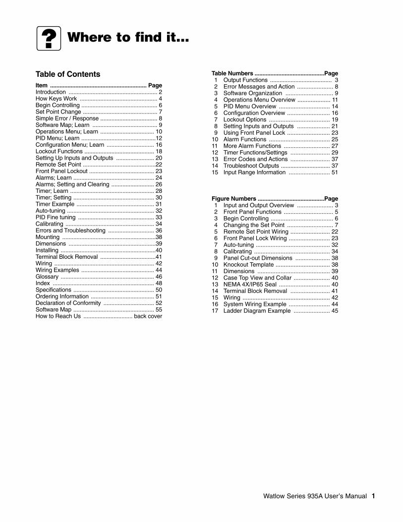
Table of ContentsItem ............................................................. PageIntroduction ........................................................ 2How Keys Work ................................................. 4Begin Controlling ................................................ 6Set Point Change ............................................... 7Simple Error / Response .................................... 8Software Map; Learn ......................................... 9Operations Menu; Learn .................................. 10PID Menu; Learn ...............................................12Configuration Menu; Learn .............................. 16Lockout Functions ............................................ 18Setting Up Inputs and Outputs ........................ 20Remote Set Point ..............................................22Front Panel Lockout ......................................... 23Alarms; Learn ................................................... 24Alarms; Setting and Clearing ........................... 26Timer; Learn ..................................................... 28Timer; Setting ................................................... 30Timer Example ................................................. 31Auto-tuning ....................................................... 32PID Fine tuning ................................................ 33Calibrating ........................................................ 34Errors and Troubleshooting ............................. 36Mounting ...........................................................38Dimensions .......................................................39Installing ............................................................40Terminal Block Removal ...................................41Wiring ............................................................... 42Wiring Examples .............................................. 44Glossary ........................................................... 46Index ................................................................ 48Specifications ................................................... 50Ordering Information ........................................ 51Declaration of Conformity ................................ 52Software Map ................................................... 55How to Reach Us ............................... back cover
Table Numbers ............................................Page1 Output Functions ....................................... 32 Error Messages and Action ...................... 83 Software Organization ............................. 94 Operations Menu Overview .................... 115 PID Menu Overview ............................... 146 Configuration Overview .......................... 167 Lockout Options ..................................... 198 Setting Inputs and Outputs .................... 219 Using Front Panel Lock .......................... 23
10 Alarm Functions ..................................... 2511 More Alarm Functions ............................ 2712 Timer Functions/Settings ........................ 2913 Error Codes and Actions ........................ 3714 Troubleshoot Outputs ............................... 3715 Input Range Information ......................... 51
Figure Numbers ..........................................Page1 Input and Output Overview ...................... 32 Front Panel Functions .............................. 53 Begin Controlling ...................................... 64 Changing the Set Point ............................ 75 Remote Set Point Wiring ........................ 226 Front Panel Lock Wiring ......................... 237 Auto-tuning ............................................. 328 Calibrating .............................................. 349 Panel Cut-out Dimensions ..................... 38
10 Knockout Template ................................. 3811 Dimensions ............................................ 3912 Case Top View and Collar ...................... 4013 NEMA 4X/IP65 Seal ............................... 4014 Terminal Block Removal ........................ 4115 Wiring ..................................................... 4216 System Wiring Example ......................... 4417 Ladder Diagram Example ...................... 45

2 Watlow Series 935A User’s Manual
Welcome to the Watlow Series 935A!
General Description
The Series 935A is a temperature controller with countdown timer for industrial, commercial, or scientific applications. It offers 1/32DIN panel-mounting, digital indication, single temperature sensor input from a thermocouple or RTD, and dual control outputs. Outputsmay operate in combinations of heat or cool, and alarm or timer.Special Features• Easy to use operator interface and user’s manual• Compact panel footprint; 1/32 DIN size• Water and corrosion proof; IP65/NEMA 4X rated• Reliable; built to UL, CUL approved safety standards with a three year warranty• Accuracy with economy• Universal power supply for worldwide applicationUnique FeaturesThe Series 935A Output 1 can be configured as a remote set point input for a multi-loop control system, or, as an alternative, thatoutput can be a front panel lock with your switch to further reinforce the 935A’s lockout capability. The Series 935A timer functionsinclude heat/timer or cool/timer countdown modes in hours:minutes or minutes:seconds.
Introduction

Watlow Series 935A User’s Manual 3
Output 1
Output 2RDY2
1
SET
SingleInput
Dual Output
Single InputType J, K, T, N, S, E Thermocouple, 1° RTD, or 0.1° RTD
Output 1Switched dc
Heat Cool Alarm RemoteSet Point
SET
FrontPanelLockout
NONE
None
Heat Cool Alarm
30
15 45
0
Timer(Hr:Min orMin:Sec)
NONE
None
Output 2Electromechanical Relay, Switcheddc or Solid-state Relay
Table 1 - Valid Output Functions
First select Output 1: Then select Output 2:
Heat None, Cool, Alarm, Timer
Cool None, Heat, Alarm, Timer
Alarm None, Heat, Cool
Remote Set Point Heat, Cool
Front Panel Lock Heat, Cool, Alarm
None Heat, Cool, Alarm
• The function of Output 1 determinesthe options available for Output 2.
• First select the function of Output 1.Refer to the table (right), then selectthe function of Output 2.
Figure 1 - Series 935A Input and Output Overview

4 Watlow Series 935A User’s Manual
Read or change
You can simply:• Read the normally displayed actual temperature,or…• Press and hold ß to read the set point,or…1. Press and hold . and , simultaneously for three seconds to move to a software menu.2. Press and hold ß to display a choice or value.3. While continuing to press ß, press . or , to choose new data or select a new value.4. Release ß and the arrow key to complete the change.
NOTE: The normally displayed actual temperature and set point can be altered to show different combinations of actualtemperature, set point temperature, or time in hours:minutes or minutes:seconds. See [dISP] p. 16.

RDY2
1
SET
Seven-segmentalphanumeric display:• Shows process value,
set point information, time, or
• Shows prompt name or value, depending on the key combination pressed.
Set Key: ß• Configurable to shift between
normally-displayed value and setvalues. See [dISP], p.16.
• Clears a latched alarm.
LED 1:Lit when Output 1 is active.
LED 2:Lit when Output 2 is active.
RDY:Lit when the process temperature is inside the timer ready band.
Up / . (Increment)Down / ,(Decrement) Arrow Key:• Selects new information when Set
Key is pressed.
• Steps through software menus andparameters.
• Starts and stops the timer.
• To set up the control, go to theEasy Software Map, p. 9.
Figure 2 - Series 935A Front Panel Functions
Watlow Series 935A User’s Manual 5

6 Watlow Series 935A User’s Manual
Begin Controlling
1. Apply power to the system.A properly-wired Series 935A will begin controlling the thermal system as soon as you apply power to it.
2. Look at the Series 935A’s display. It is reading actual temperature, set point temperature, or time.
• To change set point, go to p. 7.• The Series 935A will auto-tune when you tell it to, go to p. 32.• If you see an error, go to p. 8.
SystemPower
RDY2
1
SET
Figure 3 - Begin Controlling

Watlow Series 935A User’s Manual 7
Change Set Point
RDY2
1
SET
Your Series 935A displays the actual process temperature when it comes from the factory. You can change it to normally displaythe set point or time. Go to p. 16, see [dISP].
1. Press and hold ß.2. Press one of the arrow keys to alter the set point either upward or downward.3. Release ß to complete the change.
Figure 4 - Changing the Set Point

8 Watlow Series 935A User’s Manual
Respond to a simple error
Display Probable Cause Recommended Action
Reversed thermo- Change the sensorcouple connection leads on Terminals+ to –. 1 and 2.
Sensor type Go to `In prompt, checkmismatch selection (see p. 20), or checkor open RTD. RTD, replace as necessary.
Sensor type Go to `In prompt,mismatch. check selection
(see p. 20).
Open Thermocouple, Check the sensor,bad connection, or replace asbroken wire. necessary.
Electrical noise. Cycle power to system. See if error clears. Check system for electricalinterference.
Control is inoperable. Check for line voltage at terminals 7 and 8.
RDY2
1
SET
• Simply correct the cause.
• Errors are non-latching and self-clearing.
• For advanced error andtroubleshootinginformation, go to p. 37.
If You See An Error Code:1. Be aware that most errors are input (sensor) related.2. Read the table below and follow its recommendations.
Table 2 - Error messages and recommended action
[`Er1]
[`Er2]
[`Er3]
[`Er4]
[`Er5]
[````]

Watlow Series 935A User’s Manual 9
Software Organization
• The Series 935A has three primary menus in addition to a normal display.
• The software reverts to the normal display after 60 ± 5 sec.
Table 3 - Software Organization
• At the [`pid] or [Cnfg] prompt, press and hold the ß key, and the . or , key to select [`yes]. Release the keys tomove to the new menu.
Navigation Example
Learn the Software Map
,
,
,
DisplayActual Temperature, Set Point, or Time Remaining
Operations, p. 10
Start / Stop:•AutotuneSet:•Alarm Ranges•Countdown Timer•Idle after TimerSelectSet Point Type:Go to:PID MenuConfiguration Menu
PID, p. 12
Set:•Heat PID Functions•Dead Band•Cool PID Functions•Calibration Offset
Configuration, p. 16
Set:•Inputs / Functions•Output Types•Display Default•Alarms / Functions•Timer Functions•Failure Mode•Lockout Functions
[`yes]
[`yes]
• To access the Operations Menu, press the . and , keys simultaneously for three seconds.
• Move through each menu with the . or , key.
• Make changes by pressing and holding the ß key, andthen the . or , key to select a new choice orvalue. Release the keys to complete the change.
• To exit any menu: Press and hold the . and , keys for three seconds, or the display will revert to normal display after 60± 5 seconds.
[Prnc] [Prno [dEnc [dEno
[`Ot2]
[disp]
[Alty]
,
.
.
., , , ,

10 Watlow Series 935A User’s Manual
The Series 935A Operations Menu is the first menu you encounter when you press the . and , keys simultaneously for threeseconds. The Operations Menu provides a location to initiate the following actions or complete the following tasks:
• Auto-tune [`Aut]: Start or stop the auto-tuning process. Auto-tuning selects a set of viable proportional, integral, and derivativevalues for heat and/or cool output.
• Alarm Points, [`ALO] and [`AhI]: Select the values for the high alarm point and the low alarm point. Alarm points, dependenton sensor type high and low ranges, reside in the Operations Menu for easy access.
• Timer Countdown Time [tMr]: Select a countdown time value between 00:00 and 99:59 hours:minutes or minutes:seconds.Time interval choices [thM] and [tMS] reside in the Configuration Menu for Output 2.
• Idle Set Point [IDLE]: [trAc] or an adjustable value between [``rL] and [``rh]. Choose to have the Idle Set Point track[trAc], or equal, the Primary Set Point; or select an Idle Set Point value in °F or °C between the range low [``rL] and rangehigh [``rh] values. The Idle Set Point is active both before and after the timing sequence. The normal or Primary Set Point con-trols during the timing sequence.
• Local/Remote Set Point [`L-r], [```L] or [```r]: Choose to maintain control with the Primary [```L] (local) Set Point, or toenable the Remote [```r] Set Point if the Output 1 [`Ot1] choice equals Remote Set Point [`rSP].
• Go to the PID Menu [`Pid]: Choose [`YES] to proceed to the PID Menu.
• Go to the Configuration Menu [CnFg]: Choose [`YES] to proceed to the Configuration Menu.
The table on the next page presents this information in graphic form.
NOTE: Not every prompt listed here or on p. 11 in the Operations Menu will appear in your unit. Prompts vary withlockout function and output set-up. Whether or not prompts appear in the Operations Menu depends on two features ofthe Series 935A:
• Lockout function; the Lockout Tag [`tAg] function masks prompts from view in the various menus. (If you cannot see a prompt,you can make no change.) See Using Lockout Functions, p. 18, for more information.
• Output 1 and 2 Configuration; some outputs are mutually exclusive. For example, if Output 1 is Alarm, then Output 2 cannot beTimer. Therefore, the Operations menu will have no timer-related prompts. See the Valid Output Functions Table, p. 3, or SettingUp Inputs and Outputs, p. 20.
Learn the Operations Menu
Watlow Series 935A User’s Manual 11
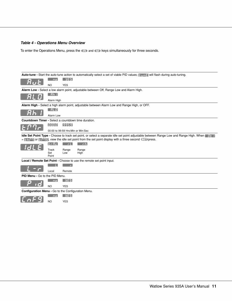
Table 4 - Operations Menu Overview
To enter the Operations Menu, press the . and , keys simultaneously for three seconds.
Auto-tune - Start the auto-tune action to automatically select a set of viable PID values; [tunE] will flash during auto-tuning.[``no] [`YES]
NO YES
Alarm Low - Select a low alarm point, adjustable between Off, Range Low and Alarm High.[`AhI]
Alarm High
Alarm High - Select a high alarm point, adjustable between Alarm Low and Range High, or OFF.[`ALO]
Alarm Low
Countdown Timer - Select a countdown time duration.[0)º0] [9959]
00:00 to 99:59 Hrs:Min or Min:Sec
Idle Set Point Type - Choose to track set point, or select a separate idle set point adjustable between Range Low and Range High. When [`Ot1]
= [thM] or [tMS], view the idle set point from the set point display with a three second ßpress.[trAc] [``rL] [``rh]
Track Range RangeSet Low HighPoint
Local / Remote Set Point - Choose to use the remote set point input.[```L] [```r]
Local Remote
PID Menu - Go to the PID Menu.[``no] `YES]
NO YES
Configuration Menu - Go to the Configuration Menu.[``no] `YES]
NO YES
[`Aut]
[`ALO]
[`AhI]
[tMr]
[IDLE]
[`L-r]
[`Pid]
[CnFg]

12 Watlow Series 935A User’s Manual
Choose the PID Strategy
You may rely solely on the Auto-tune [`Aut] function (p. 32) and factory defaults to determine PID values for your system, or you mayuse auto-tuning and additional manual adjustments. You must select dead band [``db] and calibration offset [`CAL] values manu-ally.
The Series 935A PID Menu is the first sub-menu you encounter after moving to the Operations Menu. The PID Menu provides a soft-ware location to select the individual heat or cool proportional band, hysteresis, and cycle time values; and the dead band, integral,derivative, and calibration offset values.
To go to the PID Menu:
1. Go first to the Operations Menu by pressing . and , simultaneously for three seconds.
2. Scroll through the Operations Menu with , until you see the [`Pid] prompt.
3. While pressing ß to display [``no], choose [`YES] with . or ,.
4. Release ß to see the first PID prompt.
NOTE: Access to the PID Menu and the prompts there varies with lockout function and output set-up. The PID Menu islocked out when the 935A leaves the factory.
• Lockout function; the Lockout Tag [`tAg] function masks menus from view (if you cannot see a prompt, you can make nochange). See Using Lockout Functions, p. 18.
• Output set-up; you must choose [hEAt] or [COOL] in either Output 1 or Output 2 to have access to the PID Menu. With a [hEAt]only choice, [COOL] prompts are not visible, and vice versa. See the Valid Output Functions Table, p. 3, or Setting Up Inputs andOutputs, p. 20.
NOTE: Proportional Band, Integral, Derivative, Dead Band, and Calibration Offset values are adjustable in whole or tenth°F or °C, depending on input type [``In] and [`C_F] Celsius/Fahrenheit Configuration Menu choices.
Learn the PID Menu

Watlow Series 935A User’s Manual 13
Set the PID Menu Values
• Proportional Band, Heat and Cool [Pb`h] and [Pb`c]: Select a value (degrees) to set up band on either side (±) of thePrimary Set Point in which the heat and/or cool proportioning function(s) will be active. For on/off control, set [Pb`h] or [Pb`c] = 0.
Range: 0 to 999°F/555°C, or 0.0 to 999.0°F/555.0°CDefault: 25°F/17°C, or 25.0°F/17.0°C
• Hysteresis, Heat and Cool [hYSh] and [hYSc]: For use with on/off control only. Select the value (degrees) for the process vari-able change required to re-energize the control heat and/or cool output. For ON/off control, set [Pb`h] or [Pb`c] = 0.
Range: 1 to 999°F/555°C, or 0.1 to 999.0°F/555.0°CDefault: 3°F/2°C, or 3.0°F/2.0°C
• Cycle Time, [Ct`h] and [Ct`c]: Select the value (seconds) required for the heat and/or cool output(s) to complete a full ONthrough off cycle.
Range: Switched dc/Solid State Relay: 0.1 to 60.0 secondsDefault: 5.0 secondsRange: Electromechanical Relay: 5.0 to 60.0 secondsDefault: 30.0 seconds
• Dead Band [``db]: Dead Band adjusts the effective cool set point above the primary set point by the Dead Band value in de-grees. This creates a band between the heating and cooling proportional bands where only integral and derivative activity willoccur. For more information on Dead Band fine tuning, go to p. 33.
Range: 0 to 999°F/555°C, or 0.0 to 999.0°F/555.0°CDefault: 0°
• Integral [``It]: Select a value (minutes/repeat) for the integral function. Integral is the inverse of Reset; It(value) =1/Reset(value).
Range: 0.00 to 99.99 minutes/repeatDefault: 5.00 minutes/repeat
• Derivative [``dE]: Select a value (minutes) for the derivative function.
Range: 0.00 to 9.99 minutesDefault: 0.00 minutes
• Calibration Offset [`CAL]: Eliminates the difference between the displayed process temperature and the actual process temper-ature value.
Range: -999 to 9999°F/C, or -99.9 to 999.9F/CDefault: 0°

14 Watlow Series 935A User’s Manual
Table 5 - PID Menu Overview
Set-Up HeatProportional Band Heat - Select a heat proportional band value.
[```0] [`999] [```0] [`555] [``)0] [99(0] [``)0] [55%0]
0°F to 999°F, or 0°C to 555°C, or 0.0°F to 999.0°F, or 0.0°C to 555.0°C
Hysteresis Heat - Select a heat ON/off control switching hysteresis.[```1] [`999] [```1] [`555] [``)1] [99(0] [``)1] [55%0]
1°F to 999°F, or 1°C to 555°C, or 0.1°F to 999.0°F, or 0.1°C to 555.0°C
Cycle Time Heat - Select a cycle time for the heat output.[``)1] [`6)0] [``%0] [`6)0
0.1 to 60.0 seconds 5.0 to 60.0 seconds(SSR or Switched dc) (Electromechanical Relay)
Dead Band - Select a dead band value.[```0] [`999] [```0] [`555] [``)0] [99(0] [``)0] [55%0]
0°F to 999°F, or 0°C to 555°C, or 0.0°F to 999.0°F, or 0.0°C to 555.0°C
Set-Up CoolProportional Band Cool - Select a cool proportional band value.
[```0] [`999] [```0] [`555] [``)0] [99(0] [``)0] [55%0
0°F to 999°F, or 0°C to 555°C, or 0.0°F to 999.0°F, or 0.0°C to 555.0°C
Hysteresis Cool - Select a cool ON/off control switching hysteresis.[```1] [`999] [```1] [`555] [``)1] [99(0] [``)1] [55%0
1°F to 999°F, or 1°C to 555°C, or 0.1°F to 999.0°, or 0.1°C to 555.0°C
Cycle Time Cool - Select a cool output cycle time.[``)1] [`6)0] [``%0] [`6)0
0.1 to 60.0 seconds 5.0 to 60.0 seconds(SSR or Switched dc) (Electromechanical Relay)
[Pb`h]
[hySh]
[Ct`h]
[``db]
[Pb`c]
[hySc]
[Ct`c]
Learn the PID Menu - Details

Watlow Series 935A User’s Manual 15
Set-Up GeneralIntegral Function - Select an integral value.
[`)00] [9(99]
0.00 to 99.99 minutes/repeat
Derivative Function - Select a derivative value.[`)00] [`(99
0.00 to 9.99 minutes
Calibration Offset - Select a calibration offset value.[-999]] [9999] [-9(9] [99(9
-999° to 9999°F or C or -99.9° to 999.9°F or C
Note: Access to the PID Menu and the prompts there varies with lockout function and output set-up. The PID Menu islocked out when the 935A leaves the factory.
• Lockout function; the Lockout Tag [`tAg] function masks menus from view (if you cannot see a prompt, you can make nochange). See Using Lockout Functions, p. 18.
• Output set-up; you must choose [hEAt] or [COOL] in either Output 1 or Output 2 to have access to the PID Menu. With a[hEAt] only choice, [COOL] prompts are not visible, and vice versa. See the Valid Output Functions Table, p. 3, or Setting UpInputs and Outputs, p. 20.
[``It]
[``dE]
[`CAL]

16 Watlow Series 935A User’s Manual
The Configuration Menu is the second sub-menu in the Operations Menu. Use it to set Inputs, Ranges, Output Types, Alarms, Timer,Failure Mode, and Lockouts.
To go to the Configuration Menu:
1. Go first to the Operations Menu by pressing . and , simultaneously for three seconds.
2. Scroll through the Operations Menu with , until you see the [CnFg] prompt.
3. While holding ß to display [``no], choose [`YES] with . or ,.
4. Release ß to see the first [CnFg] prompt, [``In].
5. To leave the Configuration Menu, press . and , for 3 seconds.
Table 6 - Configuration Menu Overview
Input Type - Choose sensor type. See p. 21 for sensor ranges.[```J] [```H] [```t] [```n] [```E] [```S] [`rtd] [`r†d]
J t/c K t/c T t/c N t/c E t/c S t/c 1.0° RTD 0.1° RTD
Celsius/Fahrenheit - Choose displayed unit of measure.[``°F] [``°C]
°F °C
Input Range Low - Select lowest displayable set point. Ranges, p. 21.[``In] [``rh]
Select a value (lowest displayable set point) between Input Type Range Low and Input Range High.
Input Range High - Select highest displayable set point. Ranges, p. 21.[``Rl [``In]]
Select a value (highest displayable set point) between Input Type Range High and Input Range Low.
Output 1 Function - Choose Output 1 type; see Valid Outputs Table, p. 21.
[hEAt] [COOL] [ALM] [`rSP] [`FPL]] [nonE]]
Heat Cool Alarm Remote Front NoneSet Point Panel Lock
Output 2 Function - Choose Output 2 type (dependent on Output 1 choice).hEAt] [COOL] [ALM] [thM] [tMS] [nonE]]
Heat Cool Alarm Timer Timer NoneHr./Min. Min./Sec
Display Default - Choose the primary (last 2 characters) and secondary (first 2 characters) default displays. Press ß to toggle to the secondary displayfor 15 seconds.
[``Ac] [AcSP] [Acti] [tiAc] [tiSP]
No Actual Actual Time Time remainingsecondary temp. temp. remaining Set point temperatureActual Set point Time Actualtemp. temp. remaining temp.
Alarm Type - Choose alarm type with output action.[Prnc] [Prno] [dEnc] [dEno]
Process Process Deviation Deviationnormally normally normally normallyclosed open closed open
[``In]
[`C_F]
[``rL]
[``rh]
[`Ot1]
[`Ot2]
[dISP]
[ALty]
Learn the Configuration Menu

Watlow Series 935A User’s Manual 17
NOTE: Access to Configuration Menu varies with lockout function. See p. 19.
Alarm Hysteresis - Choose alarm switching band.[```1[ [`999] [```1] [`555] [``)1] [99(0] [``)1] [55%0]
1°F to 999°F, or 1°C to 555°C, or 0.1°F to 999.0°F, or 0.1°C to 555.0°C
Alarm Latch - Choose latching or non-latching alarms. A latching alarm requires a ß press to clear it after the alarm condition clears.
[``no] [`YES]
NO YES
Alarm Silencing - Choose to silence alarms on startup, or not.[`SIL] = [`YES] silence an alarm with a ß press.
[``no] [`YES
NO YES
Failure Mode - Choose output action after a sensor failure. Bumpless transfer provides a smooth transition to percent power control without output state change.
[bPLS] [-100] [`100]
Bumpless Percent Power
Timer Output Function - Choose output function for the end of the timer. Delay ON = Turn ON, Delay Off = Turn off, Signal ON = Toggle ON, Signal off = Toggle off
[dLon] [dLoF] [SGon] [SGof]
Delay Delay Signal Signal on Off On Off
Start Timer Function - Choose the start timer conditions: [IMd] = Immediate start on a , press; [`rdy] =, press and Actual temp. is inside the Ready Band; [rdYA] = , press, plus Actual temp. is inside the Ready Band, then acknowledge with a ß press; [PWr] = immediate start on power-up without waiting for the Ready Band temp. or a , press.
[IMd] [`rdY] [rdYA] [PWr]
Immediate Ready Ready PowerAcknowledge
Timer Ready Band - If [Strt]= [`rdY] or [rdYA], select ready band high/low values.[```0] [`999] [```0] [`555] [``)0] [99(0] [``)0] [55%0]
0°F to 999°F, or 0°C to 555°C, or 0.0°F to 999.0°F, or 0.0°C to 555.0°C
Signal Time - If [tIM] = [SGon] or [SGoF], select a Signal ON or Signal off time duration to trigger an annunciator or other action at completion ofcountdown time.
[```1] [9959]
1 sec. to 99:59 min:sec.
Set Point Lock - Choose to lock the Primary Set Point from change, not view.[``no] [`YES]
NO YES
Lockout Tag - Choose undisplayable/unchangeable menus; [PCOA] = all locked.
[PCOA] [PCO`] [PC`A] [PC``] [P`OA] [P`O`] [P``A] [P```]
[`COa] [`CO`] [`C`A] [`C``] [``OA] [``O`] [```A] [````]Choose the menus / function that will not be displayed, and therefore cannot be changed.P = PID Menu, C = Configuration Menu (except [`tAG]), O = Operations Menu (except [CnFG]), A = Auto-tune.
[AhyS]
[`LAt]
[`SIL]
[FAIL]
[tIM]
[Strt]
[`rdy]
[``St]
[SLOC]
[`tAg]

18 Watlow Series 935A User’s Manual
The Series 935A offers three different security, or “lockout,” options. Set up one or all three lockout op-tions in the Configuration Menu.
∫
• Front Panel Lock [`FPL] uses a control output as an input for an external hardware switch; itrequires wiring, see p. 23. Choose Front Panel Lock [`FPL] as an exclusive Output 1 choice.Output 2 offers heat, cool, or alarm.
• Choose Set Point Lock [SLOC] as the simplest lockout option. It locks the Primary Set Pointfrom change, but not from view.
• Choose the Security Tag [`tAG] as a means of masking the Series 935A software menus fromview. By selecting all or part of the four-digit binary acronym, [PCOA] (Proportional / Configuration/ Operation / Auto-tune), you can choose to mask those items from view, and therefore fromchange. For example: In the Configuration Menu [`tAG] set-up, if you can see the P, the opera-tor cannot see the PID menu.
• Exceptions to [PCOA] [`tAG] are:
“C” does not lock out [`tAG].
“O” does not lock out [CnFG].
∫
WARNING: When Output 1 is a Front Panel Lock [`OT1] = [`FPL] , the output is energized!Do not connect a power switching device to Output 1; injury or death or damage toequipment or property could result.
Configuration Menu
[``In]Input Type
[`C_F]Celsius/Fahrenheit
[``rL]Input Range Low
[``rh]Input Range High
[`Ot1] Output 1 Function
[`Ot2]Output 2 Function
[dISP]Display Default
[ALty]Alarm Type
[AhYS]Alarm Hysteresis
[`LAt]Alarm Latch
[`SIL]Alarm Silencing
[FAIL]Failure Mode
[tIM]Timer Function
[Strt]Start Timer
[`rdY]Timer Ready Band
[``St]Signal Time
[SLOC] Set Point Lockout
[`tAG] Lockout Tag
Using Lockout Functions

Watlow Series 935A User’s Manual 19
View Process Yes Yes Yes Yes Yes Yes Yes
View Set Point Yes Yes Yes Yes Yes Yes Yes
Change Set Point No Yes No Yes Yes Yes Yes
Auto-tune No Yes Yes Yes Yes Yes No
View, Change Operation Menu No Yes Yes Yes Yes No YesView, Change Configuration Menu (except tag) No Yes Yes Yes No Yes Yes
View, Change PID No Yes Yes No Yes Yes Yes
RDY
2
1
SET
[`fpl]
[PCOA]
[````] = No Lockout
= Fully Locked
= Operator'sPerspective
Set Point LockoutFront Panel Lockout Security Tag
Three LockoutOptions
Note: Front Panel Lockout requires an external hardwareswitch. For [`FPL] set-up and wiring information, see p.23. For more wiring information, see p. 43.
P = PID Menu
C = Configuration Menu (except [`tag])
O = Operations Menu (except [CnFG])
A = Auto-tune
Table 7 - Series 935A Lockout Options
[`Ot1] [SLOC] [`tAG]
[slOC]
SP
[`fpl] [`YES] [P```] [`C``] [``O`] [[```A][``no]

20 Watlow Series 935A User’s Manual
Setting Inputs and Outputs
Key Input/Output Set-up Information
• All initial input and output set-up occurs in the Configuration Menu.
• The 935A requires a thermocouple or RTD input connection to the S1 and S2 Terminals, includingwhen using the remote set point [`rSP] option.
• Remote Set Point [`rSP] is a second input, wired to OT1 Terminals 3 and 4.
• Indication of °C or °F units of measure occurs only in the [`C_F] prompt.
• Sensor input type minimum and maximum range (see p. 51) is further defined with Range Low[``rL] and Range High [``rh] to set the working span of set points and remote set point scal-ing.
• Output 1 and Output 2 configure the prime functions of the Series 935A, they are the “golden”prompts.
• Output 1 must be heat or cool to use Output 2 as a timer.
• Remote Set Point [`rSP] enables Output 1 to act as an input for 0-5Î (dc) from another con-troller or a transmitter.
• Front Panel Lock [`FPL] requires an external switch and 62Ω 0.5 watt resistor wired in parallelon Output 1. Switch open = unlocked; closed = locked. See p. 23.
• Output 2 sets timer interval in hours:minutes [thM]or minutes:seconds [tMS].
• Display Default [dISP] lets you choose the primary (last 2 characters) and secondary (first 2characters) default displays. Press ß to toggle to the secondary display for 15 seconds.
[``Ac] = Normal Display: Actual TemperatureSecondary: None
[AcSP] = Normal Display: Set Point TemperatureSecondary: Actual Temperature
[Acti] = Normal Display: Time RemainingSecondary: Actual Temperature
[TiAc] = Normal Display: Actual TemperatureSecondary: Time Remaining
[tiSP] = Normal Display: Set Point TemperatureSecondary: Time Remaining
Configuration Menu
[``In] Input Type
[`C_F] Celsius/Fahrenheit
[``rL] Input Range Low
[``rh] Input Range High
[`Ot1] Output 1 Function
[`Ot2] Output 2 Function
[dISP] Display Default
[ALty]Alarm Type
[AhYs]Alarm Hysteresis
[`LAt]Alarm Latch
[`SIL]Alarm Silencing
[FAIL]Failure Mode
[tIM]Timer Function
[Strt]Start Timer
[`rdY]Timer Ready Band
[``St]Signal Time
[SLOC]Set Point Lockout
[`tAG]Lockout Tag

Watlow Series 935A User’s Manual 21
Input Range InformationJ t/c: 32 to 1382°F or 0 to 750°CK t/c: -328 to 2282°F or -200 to 1250°CT t/c: -328 to 662°F or -200 to 350°CN t/c: 32 to 2282°F or 0 to 1250°CS t/c: 32 to 2642°F or 0 to 1450°CE t/c: -328 to 1470°F or -200 to 799°C1° RTD (DIN): -328 to 1292°F or -200 to 700°C0.1° RTD: -99.9 to 999.9°F or -99.9 to 700.0°C
Table 8 - Setting Inputs and Outputs
Input Type - Choose sensor type.[```J] [```H] [```t] [```n] [```E] [```S] [`rtd] [`r†d]
J t/c K t/c T t/c N t/c E t/c S t/c 1.0° RTD 0.1° RTD
Celsius/Fahrenheit - Choose displayed unit of measure.[``°F] [``°C]
°F °C
Input Range Low - Select lowest displayable Set Point, dependent on [``In].[``In] [``rh] Select a value (lowest displayable set point) between
Input Type Range Low and Input Range High.
Input Range High - Select highest displayable Set Point, dependent on [``In].
[``rL] [``In] Select a value (highest displayable set point) between Input Type Range High and Input Range Low.
Output 1 Function - Choose Output 1 type.[hEAt] [COOL] [ALM] [`rsP] [`FPL] [nonE]Heat Cool Alarm Remote Front None
Set PanelPoint Lock
Output 2 Function - Choose Output 2 type (dependent on Output 1 choice).[hEAt] [COOL] [ALM] [thM] [tMS] [nonE]
Heat Cool Alarm Timer Timer NoneHr./Min. Min./Sec
Display Default - Choose the primary (last 2 characters) and secondary (first 2 characters) default displays. Press ß to toggle to the secondary displayfor 15 seconds.
[``Ac] [[AcSP]] [Acti] [tiAc] [tiSP]
No secondary Actual temperature Actual temperature Time remaining Time remainingActual temperature Set point Time remaining Actual temperature Set point temperature
temperature
Valid Output FunctionsFirst select Output 1: Then select Output 2:Heat None, Cool, Alarm, TimerCool None, Heat, Alarm, TimerAlarm None, Heat, CoolRemote Set Point Heat, CoolFront Panel Lock Heat, Cool, AlarmNone Heat, Cool, Alarm
Note: Access to Configuration Menu varies with lockout function. See p. 19.
• The function of Output 1 determines the options available for Output 2.
• First select the function of Output 1.Refer to the table (right), then selectthe function of Output 2.
[``In]
[`C_F]
[``rL]
[``rh]
[`Ot1]
[`Ot2]
[dISP]

22 Watlow Series 935A User’s Manual
To Set Up Remote Set Point…
1. Wire the control per the example below and the information on p. 42-45.
2. Go to [CnfG], make [`in] and [`c_f] choices, then
3. Make [``In] and [`C_F] choices, then
4. Scale the 0-5VÎ (dc) input with [``rL] and [``rh].
5. Go to [`Ot1], and choose [`rSP].
6. Go to the Operations Menu; [`L-r], choose [```r].
Output 1
[`Ot1] [`rSP] Select Remote Set Point for Output 1
Local / Remote
[`L-r] [```L] Local set point active
[```r] Remote set point active
• Remote Set Point is scaled by [``rh] and [``rL].
• 0V input results in a set point of [``rL].
• 5V input results in a set point of [``rh].
• Adjust [``rL] and [``rh] to match your input to desired set point adjustment.
• The Remote Set Point will display instead of Primary Set Point.
• Auto-tune always uses the Primary Set Point.
• Deviation Alarm uses the active Set Point.
Figure 5 - Remote Set Point WiringSee p. 42-45 for more wiring information.
NOTE: Sensor required on Terminals 1 and 2.
∫WARNING: All wiring and fusing must conform to local and national electric codes.Contact local authorities for further information. Failure to comply with electric codescould result in injury or death, or damage to property.
S2–1
S1+2
–3
+4 5 6 7 8
OT1IN OT2 POWER
Configuration Menu
[``In]Input Type
[`C-F]Celsius/Fahrenheit
[``rL] Input Range Low
[``rh] Input Range High
[`Ot1] Output 1 Function
[`Ot2]Output 2 Function
[dISP]Display Default •••
[FAIL]Failure Mode
[SLOC]Set Point Lockout
[`TAG]Lockout Tag
OperationsMenu
[`Aut]Auto-tune
[`L-r] Local / Remote
[`Pid]PID
[CnFG]Configuration
Set Up Remote Set Point Input
Watlow Series 935A User’s Manual 23
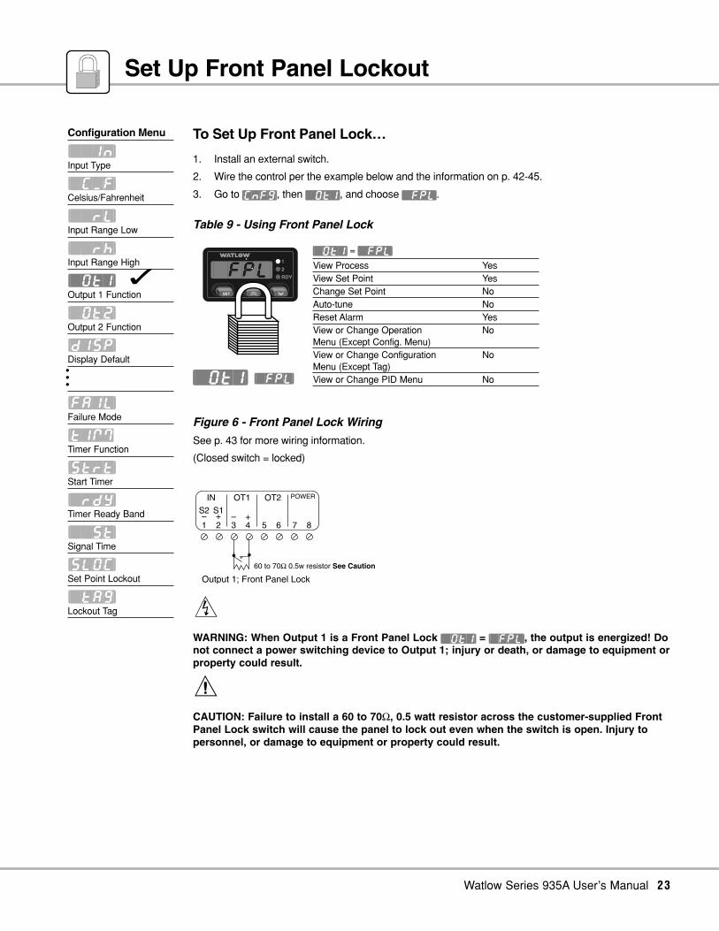
To Set Up Front Panel Lock…
1. Install an external switch.
2. Wire the control per the example below and the information on p. 42-45.
3. Go to [CnFG], then [`Ot1], and choose [`FPL].
Table 9 - Using Front Panel Lock
Figure 6 - Front Panel Lock Wiring
See p. 43 for more wiring information.
(Closed switch = locked)
∫
WARNING: When Output 1 is a Front Panel Lock [`Ot1] = [`FPL], the output is energized! Donot connect a power switching device to Output 1; injury or death, or damage to equipment orproperty could result.
ç
CAUTION: Failure to install a 60 to 70Ω, 0.5 watt resistor across the customer-supplied FrontPanel Lock switch will cause the panel to lock out even when the switch is open. Injury topersonnel, or damage to equipment or property could result.
Output 1; Front Panel Lock
S2–1
S1+2
–3
+4 5 6 7 8
OT1IN OT2 POWER
60 to 70Ω 0.5w resistor See Caution
Configuration Menu
[``In]Input Type
[`C_F]Celsius/Fahrenheit
[``rL]Input Range Low
[``rh]Input Range High
[`Ot1] Output 1 Function
[`Ot2]Output 2 Function
[dISP]Display Default•••
[FAIL]Failure Mode
[tIMTimer Function
[Strt]Start Timer
[`rdY]Timer Ready Band
[``St]Signal Time
[SLOC]Set Point Lockout
[`tAG]Lockout Tag
[`Ot1] [`FPL]
Set Up Front Panel Lockout
[`Ot1] = [`FPL]
View Process YesView Set Point YesChange Set Point NoAuto-tune NoReset Alarm YesView or Change Operation NoMenu (Except Config. Menu)View or Change Configuration NoMenu (Except Tag)View or Change PID Menu No
RDY
2
1
SET
[`fpl]
24 Watlow Series 935A User’s Manual
Configuration Menu
[``In]Input Type
[`C_F]Celsius/Fahrenheit
[``rL]Input Range Low
[``rh]Input Range High
[`Ot1]Output 1 Function
[`Ot2]Output 2 Function
[dISP]Display Default
[ALtY] Alarm Type
[AhYS] Alarm Hysteresis
[`LAt] Alarm Latch
[`SIL] Alarm Silencing
[FAIL]Failure Mode
OperationsMenu
[`Aut]Auto-tune
[`ALO] Alarm Range Low
[`AhI] Alarm Range High
[`Pid]PID
[CnFG]Configuration
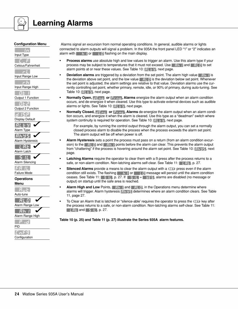
Learning Alarms
Alarms signal an excursion from normal operating conditions. In general, audible alarms or lightsconnected to alarm outputs will signal a problem. In the 935A the front panel LED “1” or “2” indicates analarm with [``hI] or [``LO] flashing on the main display.
• Process alarms use absolute high and low values to trigger an alarm. Use this alarm type if yourprocess may be subject to temperatures that it must not exceed. Use [`AhI] and [`ALO] to setalarm points at or near these values. See Table 10: [ALtY], next page.
• Deviation alarms are triggered by a deviation from the set point. The alarm high value [`AhI] isthe deviation above set point, and the low value [`ALO] is the deviation below set point. Wheneverthe set point is adjusted, the alarm settings are relative to that value. Deviation alarms use the cur-rently controlling set point, whether primary, remote, idle, or 90% of primary, during auto-tuning. SeeTable 10: [ALtY], next page.
• Normally Open, [dEno] or [Prno], Alarms energize the alarm output when an alarm conditionoccurs, and de-energize it when cleared. Use this type to activate external devices such as audiblealarms or lights. See Table 10: [ALtY], next page.
• Normally Closed, [dEnc] or [Prnc], Alarms de-energize the alarm output when an alarm condi-tion occurs, and energize it when the alarm is cleared. Use this type as a “deadman” switch wheresystem continuity is required for operation. See Table 10: [ALtY], next page.
For example, by running the control output through the alarm output, you can set a normallyclosed process alarm to disable the process when the process exceeds the alarm set point.The alarm output will be off when power is off.
• Alarm Hysteresis sets a point the process must pass on a return (from an alarm condition excur-sion) to the [`ALO] and [`AhI] points before the alarm can clear. This prevents the alarm outputfrom “chattering” if the process is hovering around the alarm set point. See Table 10: [AhYS], nextpage.
• Latching Alarms require the operator to clear them with a ß press after the process returns to asafe, or non-alarm condition. Non-latching alarms self-clear. See Table 11: [`LAt], p. 27.
• Silenced Alarms provide a means to clear the alarm output with a ß press even if the alarmcondition still exists. The flashing [``hI] or [``LO] message will persist until the alarm conditionceases. See Table 11: [`SIL], p. 27. If [`SIL] = [`YES], alarms are disabled (no message oroutput) on startup until the safe area is reached.
• Alarm High and Low Points, [`AhI] and [`ALO], in the Operations menu determine wherealarms will trigger. Alarm hysteresis [AhYS] determines where an alarm condition clears. See Table11, page 27.
• To Clear an Alarm that is latched or “silence-able’ requires the operator to press the ß key afterthe process returns to a safe, or non-alarm condition. Non-latching alarms self-clear. See Table 11:[`LAt] and [`SIL], p. 27.
Table 10 (p. 25) and Table 11 (p. 27) illustrate the Series 935A alarm features.

Watlow Series 935A User’s Manual 25
Table 10 - Alarm Functions
Set Point
Deviationnormallyclosed
Deviationnormallyopen
Processnormallyclosed
Processnormallyopen
Non-Alarm StateLED offAlarm Output:
Alarm StateLED onAlarm Output Status:
Function
A deviation alarmtracks set point.
A process alarmis a fixed value,independentof set point.
Alarm High Region
Alarm Low Region
SafeArea
SafeArea
Alarm Type
Alarm Hysteresis is the change in the process variable (actual) required to clear the alarm relay after an alarm occurs.
Alarm High Region
Alarm Low Region0
Silenced-Alarm StateLED offAlarm Output Status:
Power-Off StateLED offAlarm Output Status:
Deviation Alarm Process Alarm
[ALtY] [dEnc] [dEno] [Prnc] [Prno]
[AhYS]
[AhYS]
[AhYS]
[AhYS]
[AhYS]

26 Watlow Series 935A User’s Manual
1. Plan an alarm strategy. What do you want to happen when an alarm occurs?
2. Wire the appropriate control output, Output 1 or Output 2, and associated switching and annuncia-tors. See p. 42-45 for wiring information.
3. Go to the 935A’s Configuration Menu [CnFG]. See p. 16.
4. Set either Output 1 [`Ot1] or Output 2 [`Ot2] as the [ALM] output.
5. Set Alarm Type [ALty].
6. Set alarm hysteresis [AhYS].
7. Set alarm latching [`LAt].
8. Set alarm silencing [`SIL].
9. Set a failure mode [FAIL]. See p. 36-37.
10. Go to the 935A’s Operation Menu. See p.10.
11. Set the alarm high and low [`ALO] and [`AhI] points.
12. Test and adjust the alarm system.
13. Document the alarm settings and system.
ç
CAUTION: Verify, in Table 10, p. 25, the alarm state / alarm output condition you want beforemaking the Alarm Type [ALty] choice. Failure to do so could result in damage to equipmentand property.
ç
WARNING: Do not rely on the Series 935A alarms to provide redundant temperature limitcontrol. Use correctly specified, properly installed temperature limit controls instead. Failureto do so could result in injury, death or damage to equipment and property. (Seeaccompanying Watlow Bulletin 89.4.3.)
To Clear a Series 935A Alarm
In general, press the ß key to clear a latched or ‘silence-able’ ([`sil] = [yes]) alarm.
Ultimately, the system process value must return within the safe area for the alarm to remain clear. Non-latching alarms self-clear.
Configuration Menu
[``In]Input Type
[`C_F]Celsius/Fahrenheit
[``rL]Input Range Low
[``rh]Input Range High
[`Ot1]Output 1 Function
[`Ot2]Output 2 Function
[dISP]Display Default
[AltY] Alarm Type
[AhYS] Alarm Hysteresis
[`LAt] Alarm Latch
[`SIL] Alarm Silencing
[FAIL]Failure Mode
OperationsMenu
[`Aut]Auto-tune
[`ALO] Alarm Range Low
[`AhI] Alarm Range High
[`Pid]PID
[CnFG]Configuration
Setting Alarms
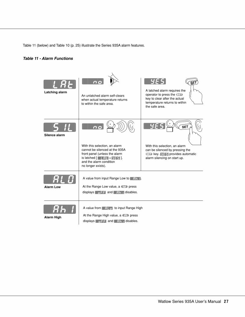
Table 11 (below) and Table 10 (p. 25) illustrate the Series 935A alarm features.
Table 11 - Alarm Functions
SET
Latching alarm
Silence alarm
With this selection, an alarmcannot be silenced at the 935Afront panel (unless the alarmis latched [ [~LAt] = [yes] ],and the alarm conditionno longer exists).
SET
A value from input Range Low to [`AhI].
A value from [`alo] to input Range High
Alarm Low
Alarm High
An unlatched alarm self-clears when actual temperature returns to within the safe area.
At the Range Low value, a , press
displays [`off] and [`ahi] disables.
At the Range High value, a . press
displays [`off] and [`ahi] disables.
[`lat]
[`sIl]
[`alO]
[`ahI]
[``no]
[``no]
[`yes]
[`yes]
A latched alarm requires the operator to press the ß
key to clear after the actual temperature returns to within the safe area.
With this selection, an alarm can be silenced by pressing theß key. [yes] provides automaticalarm silencing on start up.
Watlow Series 935A User’s Manual 27

28 Watlow Series 935A User’s Manual
Configuration Menu
[``In]Input Type
[`C_F]Celsius/Fahrenheit
[``rL]Input Range Low
[``rH]Input Range High
[`Ot1]Output 1 Function
[`Ot2] Output 2 Function
[dISP] Display Default
[ALtY]Alarm Type
[AhYS]Alarm Hysteresis•••
[tIM] Timer Function
[Strt] Start Timer
[`rdY] Timer Ready Band
[``St] Signal Time
OperationsMenu
[`Aut]Auto-tune
[tMr] Countdown Timer
[IdLE] Idle
• The timer requires Output 1 to work as either a heat or as a cool output.
• The 935A timer is a function of Output 2, which, depending on your unit’s model number, can be ei-ther switched dc, electromechanical relay, or solid state relay.
• Hours: minutes (hh:mm) or minutes:seconds (mm:ss) choices reside in Output 2 [`Ot2].
• Timer set-up occurs in two locations, in the Configuration Menu and the Operations Menu.
• , starts the timer.
• . stops the timer.
• [dISP] choices set up the timer display (see p. 16).
• LED colon flashes when timer runs.LED colon ON steadily when timer is not running.
Configuration Menu set-up includes: (see p. 16)
• Output 1 [`Ot1]; heat [hEAt] or cool [COOL].
• Output 2 [`Ot2]; timing interval, hours:minutes [thM], or minutes:seconds [tMS].
• Timer (Output 2) function [tIM] can perform one of four possible actions after timing:
1. Turn ON, also called, “delay ON” [dLon].
2. Turn off, also called, “delay off” [dLof].
3. Toggle ON, also called, “signal ON” [sgon].
4. Toggle off, also called, “signal off” [sgof].
• Start timer function [Strt] choices:
1. Immediately start [IMd].
2. Start once inside a ready band [`rdy].
3. Start once inside a ready band, acknowledging [rdya] with a ß press.
4. Start immediately on control power up [PWr] without waiting for the Ready Band temp. or a, press.
• Ready band width [`rdy] above and below set point: degrees.
• Signal time [``St] (if applicable) duration: seconds.
Operations Menu set-up includes: (see p. 10)
• Countdown Time [tMr]: hours:minutes or minutes:seconds.
• Idle Set Point Type [IdLE], two choices:
1. Track primary set point (always controls at the set point value).
2. Set an idle set point for control when not timing.
The next page presents this information in graphic format with additional detail.
30
15 45
0
Learn the Countdown Timer

Watlow Series 935A User’s Manual 29
Table 12 - Series 935A Timer Functions/Settings
Delay ON Delay OFF Signal ON Signal OFFOutput 2Timer OutputFunction;Choose one of four possible output actions for the end of the timer / time periods.
SP RDYRDY
RDY
• = 0, Disables Ready feature.• The RDY front panel LED is lit inside Ready Band for all Timer Start functions.
Timer only runs in the Ready Band. key starts timer sequence.
Ready Acknowledge. key starts timer sequence. must be pressed once inside the Ready Band to start timer at the normal display.
Sets the signal timefrom 00:01 to 99:59 min:secto run after Timer.
Signal Time
Timer starts immediately on a key press at the normal displaywithout waiting for the Ready Band temperature.
SET
Timer Function OFF.
SP
Idle
• Idle is set point used when not timing.• If Trac selected Idle is the same as Set Point.• The Set Point value controls the process during the Timer sequence.
Configuration Menu
Operations Menu
Output 2 is ON beforetiming; OFFduring tim-ing; ONafter timing.
Idle Set Point
Timer ReadyBand
Start TimerFunction
Output 2 is OFF beforetiming; ONduring tim-ing; OFFafter timing.
Output 2 is OFF before& duringtiming; ONafter timing;then OFF.
Output 2 is ON before& duringtiming; OFFafter timing;then ON.
Countdown Time
Choose time in hr:min or min:sec.
Timer set-upavailable only when = or
Timer starts immediately on control power up without waiting for theReady Band temperature or a , press. See p. 61.

30 Watlow Series 935A User’s Manual
30
15 45
0
1. Plan a timer strategy.
2. Wire the Output 2 control output, associated switching devices and annunciators. See p. 42-45.
3. Go to the 935A’s Configuration Menu [CnFG].
4. Choose the Output 2 [`Ot2] function as time; hrs:min [thM], or time; min:sec [tMS].
5. Choose a display default [dISP] (see page 16):• Actual Temperature only [``Ac]• Actual; Set Point [AcSP]• Actual; Time [Acti]• Time; Actual [tiAc]• Time; Set Point [tiSP]
6. Choose a Timer Output Function [tIM]:• Delay ON [dLon]• Delay off [dLoF]• Signal ON [sgon]• Signal off [sgoF]
7. Choose a start timer [Strt] function; either immediate [IMd], ready band [`rdY], ReadyAcknowledge [rdYA], or Power [PWr].
8. If you chose [`rdY] or [rdya], then select a ready band [`rdy] value.
9. If you chose [SGon] or [sgof], then select a signal time [``St] value.
10. Go to the 935A’s Operation Menu.
11. Set the countdown time [tMr].
12. Choose the idle set point [IdLE] to track [trAc] the primary set point, or select a separate idle setpoint value between the range high [``rh] and range low [``rL] values.
13. Run the system, and test the timer start with a ß press.
14. Document the timer settings and system.
Configuration Menu
[``In]Input Type
[`C_F]Celsius/Fahrenheit
[``rL]Input Range Low
[``rh]Input Range High
[`Ot1]Output 1 Function
[`Ot2] Output 2 Function
[dISP] Display Default
[ALty]Alarm Type
[AhYS]Alarm Hysteresis•••
[tIM] Timer Function
[Strt] Start Timer
[`rdY] Timer Ready Band
[``St] Signal Time
OperationsMenu
[`Aut]Auto-tune
[tMr] Countdown Timer
[IdLE] Idle
Setting the Countdown Timer

Watlow Series 935A User’s Manual 31
30
15 45
0
Convection Oven Application
Scenario
A master chef bakes bread at 350°F for 30 minutes. He wants the oven at the proper temperature with an indication when it is ready tobegin baking. He isn't concerned if the oven is 10° cool at first. After he loads the oven, the chef wants to start the countdown time bypressing a key. When the baking time is complete, he wants a 10 second audible indication that the bread is done.
Recommended Control
A Series 935A-1CD0-000G control.
• Switched dc Output 1 wired to a dc input solid state relay (SSR) switches the heaters.
• Electromechanical relay Output 2 wired to an AC audible indicator provides “done” indication.
Configuration Menu Set-up[`C_F] = [``°f] °F[dIsp] = [Acti] After a ß press, actual temperature appears for 15 seconds.[`Ot1] = [hEAt] Heating output[`Ot2] = [tMS] Time; minutes:seconds[tIM] = [SGon] Output 2 turns ON briefly at the end of the timing cycle.[Strt] = [rdYA] Timer waits to countdown until temperature deviation from set point < [`rdy] value and the ß key
is pressed.[`rdY] = [``10] Ready band; 10°F[``St] = [``10] Output 2 turns ON for 10 sec. at the end of the timing cycle.Operations Menu Set-up[tMr] = [3000] Bake time; 30 minutes[IdLE] = [``75] The set point temperature before a timing cycle starts and after a timing cycle completes.Set Point = [`350°F
Operator/Control Actions
• With the oven "idling" at 75°F, the chef starts the preheat cycle with a , press. The display immediately shows 30:00 with thecolon ON steadily. The RDY LED is off. Series 935A begins to control to the 350°F bake set point.
• As the actual oven temperature increases to within the Ready Band at 350°F ±10°F, the RDY LED turns on. The chef loads theoven and presses ß to acknowledge the Ready Band and thereby start the bake cycle.
• Time starts counting down. Actual temperature displays for 15 seconds after the ß key is press. Then time displays with thecolon flashing.
• If temperature deviates out of the Ready Band (less than 340°F or more than 360°F), timer countdown will pause, but will con-tinue as soon as temperature re-enters the ready band.
• When time reaches 00:00, Output 2 turns on for 10 seconds sounding the audible indicator. The chef can stop the audible indica-tor by pressing .. The Series 935A then automatically shifts to the 75°F idle set point.
Timer Example

Auto-tuning
Auto-tune automatically sets PID parameters for your system.
1. Press . and , for three seconds.
2. You'll see [`Aut].
3. Press and hold ß, then select [`YES] with . or ,. [tune] will flash to indicate auto-tun-ing. Display reverts to normal after auto-tuning.
4. [`Aut] = [``no] stops auto-tuning.
Figure 7 - Auto-tuning the Series 935A
Manual Tuning
For optimum performance, tune the Series 935A to your thermal system. The settings here are for abroad spectrum of applications; your system may have different requirements.
Tune heating outputs at a set point above ambient temperature. Tune cooling outputs at a set point below ambient temp.
1. Apply power to the 935A and enter a set point. In the Operations Menu, [`Aut] must = [``no].Begin with these Configuration Menu settings:[Pb`h = [```1], [``1t] = [`000], [``dE] = [`000],[Ct`h] = [`%0]], [`CAL] = [```0].
2. Proportional Band Adjustment: Gradually increase [Pb`h] until the upper display temp. stabilizesat a constant value.
3. Integral Adjustment: Gradually decrease [``It] from 30.00 until the display temperature begins tooscillate or “hunt.” Then slowly increase [``It] until the upper display stabilizes again near setpoint.
4. Cycle Time Adjustment: Set [Ct`h] as required. Faster cycle times sometimes achieve the bestsystem control. However, if a mechanical contactor or solenoid is switching power to the load, alonger cycle time will minimize wear on relays.
5. Derivative Adjustment: Increase [``dE] to 0.10 minute. Then raise set point by 20° to 30°F, or 11°to 17°C. Observe approach to set point. If load temperature overshoots, increase [``dE] by 0.50minute. Raise set point by 20 to 30°F, or 11 to 17°C and watch approach again. Repeat until sys-tem rises to new set point appropriately.
6. Calibration Offset Adjustment: Enter the [`CAL] offset value you want. Calibration offset adds orsubtracts degrees from the value of the input signal.
Tem
per
atu
re
Time
90%
Set Point
32 Watlow Series 935A User’s Manual
Auto-tuning
NOTE:[`Aut] is not visible at factory default.
ç
CAUTION:Successful Series935A auto-tuningrequires 3oscillations thru the90% set point in 85min. or less. If thesystem cannotperform theoscillations in thattime, the control willrevert to theprevious PID values.
NOTE: Manual tuning is aslow procedure,taking from minutesto hours to obtainoptimum value.
Operations Menu
[`Aut] Auto-tune
[`ALO]Alarm Range Low
[`Ah1]Alarm Range High
[tMr]Countdown Timer
[IdLE]Idle
[`L-r]Local / Remote
[`Pid]PID
[CnFg]Configuration
çAuto-tuning occurs at 90% of set pointin less than or equal to 85 minutes.

Watlow Series 935A User’s Manual 33
Fine Tune the PID Settings
1. Set [Pb`h] and [Ct`h] in degrees.2. If Proportional Band Heat [Pb`h] = 0, Set Hysteresis Heat [HySh]. The Series 935A will provide on/off
control with the hysteresis value selected, and no proportioning action.3. Proportional Bands should be decreased for tighter control but increased to eliminate oscillations.4. Cycle Time Heat [Ct`h] is limited to a minimum of 5.0 seconds for the electromechanical relay to help
reduce wear. The electromechanical relay (D, Output 2) is not recommended for PID control. It is war-ranted to 100,000 contact closures only. Alarm or on/off control are appropriate applications for theSeries 935A's electromechanical relay output.
5. Set Dead Band [``db] to adjust the effective cool set point above the primary set point by the deadband value in degrees. In cool/heat applications, dead band prevents continuous cool output action bycreating a buffer between heating and cooling output action.
6. Set [Pb`c] and [Ct`c] in degrees.7. If Proportional Band Cool [Pb`c] = 0, Set Hysteresis Heat [HYSc]. The Series 935A will provide on/off
control with the hysteresis value selected, and no proportioning action.8. Proportional Bands should be decreased for tighter control but increased to eliminate oscillations.9. Cycle Time Heat [Ct`h] is limited to a minimum of 5.0 seconds for the electromechanical relay to help
reduce wear. The electromechanical relay (D, Output 2) is not recommended for PID control. It is war-ranted to 100,000 contact closures only. Alarm or on/off control are appropriate applications for theSeries 935A's electromechanical relay output.
10. Set Integral [``It] to eliminate droop in the system. Lower the value for more droop reduction.Adjustable from 0 to 99.9 minutes / repeat.
11. Set Derivative [``dE] to prevent overshoot. Increasing the value slows the approach to set point.Adjustable from 0 to 9.99 minutes.
12. Calibration Offset [`Cal] eliminates the difference between the displayed process temperature and theactual process temperature value.
PID Menu
Set up Heat:
[Pb`h] Proportional Band
[hySh] Hysteresis
[Ct`h] Cycle Time
[``db] Dead Band
Set up Cool:
[Pb`c] Proportional Band
[hySc] Hysteresis
[Ct`c] Cycle Time
Set up General:
[``It] Integral
[``dE] Derivative
[`CAL] Calibration Offset

34 Watlow Series 935A User’s Manual
Calibrating the 935A
Calibration requires a precision millivolt source with thermocouple compensation, an adjustable 0-10 volt source, and a decade resistance box.• [tr50] and [tr00] calibrate the thermocouple span.• [``tc] calibrates the ambient compensation.• [r380] and [r`15] calibrate the RTD span.• 0V is required when calibrating [tc00] and [r`15]
for remote set point calibration.• 5V is required when calibrating [tc50] and [r380]
for remote set point calibration.• When calibrating, calibrate all points for consistency in results.• Allow the unit to warm up for 15 minutes before calibrating.
Quick CalibrationRestore:
Press all three keyssimultaneously until[tc50] appears in thedisplay, press .once and [`rSt] willappear in the display.Press and hold ß,the display will show[``no], press . tochange display to[`YES]. Press andhold . and ,for 3 seconds to exitthe [`CAL] menu.
NOTE: RestoreFactory Calibration[`rSt] = [`YES]restores factorycalibration values to all calibration prompts.
Figure 8a - Thermocouple Calibration
Figure 8b - RTD Calibration
Calibration Menu
[tc50] tc50
[tc00] tc00
[``tc] tc
[r`15] r15
[r380] r380
[`rSt] rst
mV source = 50.000mVVolt source = 5V
mV source = 0.000mVVolt source = 0V
mV source = Temp. CompensationVolt source = 0V
Decade Box = 15.00 ohmsVolt source = 0V
mV source = 380.00 ohmsVolt source = 5V
• Store TC counts at 50.000mV• Store 5V remote set point counts for use with TC
• Store ambient counts at 32° F. Type J.
• Store low end RTD counts• Store 0V remote set point counts for use with RTD
• Store high end RTD counts• Store 5V remote set point counts for use with RTD
• Restore factory calibration
mVsource
Voltsource
S2–1
S1+2
–3
+4 5 6 7 8
OT1IN OT2 POWER
Decade Box
Voltsource
S2–1
S1+2
–3
+4 5 6 7 8
OT1IN OT2 POWER
• Store TC counts at 0.000mV• Store 0V remote set point counts for use with TC

Watlow Series 935A User’s Manual 35
Thermocouple and Remote Set Point Input Field Calibration ProcedureEquipment Required:• Type “J” Reference Compensator with reference junction at 32°F/0°C, or Type “J” Thermocouple Calibrator set at 32°F/0°C.• Precision millivolt source, 0-50mV min. range, 0.01mV resolution.
Set Up:1. Connect 100-240Å (ac), or 24-28V‡ (ac/dc) to Terminal 7 and Terminal 8.2. Connect the millivolt source to Terminal 1 negative and Terminal 2 positive.3. Connect voltage source to Terminal 3 negative and Terminal 4 positive.4. Apply power to the unit and allow it to warm up for 15 minutes.
Move to the Calibration Menu:1. Press . and , simultaneously for 3 seconds.2. Press . or , until [CnFG] is displayed.
Press and hold ß – press . or , to select [`YES], then release ß.3. Press . or , until [`TAG] is displayed.
Press and hold ß. Press . or ,8 times (display shall be blank).
Calibration: (Thermocouple)1. Press and hold ß, ., and , simultaneously for 3 seconds until [TR50] is displayed.2. Set the mV source to 50.00mVÎ (dc). Set the voltage source to 5.00VÎ (dc). Allow 10 seconds for sources to stabilize. Press and
hold ß. Press . or , until [`YES] appears. Release ß.3. Press , - [Tc00] shall be displayed.4. Set the mV source to 0.00 mVÎ (dc), set voltage source to 0.00VÎ (dc). Allow 10 seconds for sources to stabilize. Press and holdß. Press . or , until [`YES] appears. Release ß.
5. Press ,. [``Tc] shall be displayed.6. Set the MV source to 0.00 mV (if using a temperature compensator). Set calibrator to 32°F/0°C.
Set voltage source to 0.00V. Allow 10 seconds for sources to stabilize. Press and hold ß. Press . or , until [`YES] is displayed. Release ß.
Calibration: (RTD)Equipment Required:• Precision Resistance Box with 0.01Ω Resolution.1. Remove thermocouple wires from Terminal 1 and Terminal 2.2. Connect S2 to terminal 1. Connect S1 to Terminal 2.3. Press ,. [R`15] shall be displayed.4. Connect voltage source to Terminal 3 negative and Terminal 4 positive.5. Set the Decade box to 15.00Ω, set the voltage source to 0.00V (Allow 10 seconds for sources to stabilize). Press and hold ß.
Press . or , until [`YES] appears. Release ß.6. Press , - [R380] shall be displayed.7. Set the decade box to 380.00Ω, set the voltage source to 5.00V. (Allow 10 seconds for sources to stabilize). Press and hold ß.
Press . or , until [`YES] appears. Release ß.8. Press and hold . and , for 3 seconds to Exit calibration menu.
Calibrating the 935A and Remote Set Point Input

36 Watlow Series 935A User’s Manual
Errors and Troubleshooting
Set up an input failure operation mode at the [FAIL] prompt in the [CnFG] menu; choose bumplesstransfer [bPLS] for smooth output action transition to percent power control, or select a percent poweroutput value.
[FAIL [bPLS]
Bumpless Transferwhen errors occur, the control output will continue at a percent output learned while stable. Default = [bPLS] .
[-100] [`100]
Percent Power(-100% to +100% , depending on heat/cool output configuration). The control will assume a specific output power when input errors occur.
• All except one of the possible displayed error messages are input related.
• If you see [`Er5], cycle power to the controller. If the error persists, call the factory.
• Be aware of the difference between U.S and European thermocouple color/colour codes.
• Reversed polarity input leads is one of the most common errors.
• Incorrect software input choice at the Configuration Menu [CnFG] input [``In] prompt is another common error.
When calling the factory for help, please have:1. The model number of the control.2. A photocopy of pages 55 to 62 with the settings
from your control, if possible.3. Specifications of devices directly interfaced
with the control.
Configuration Menu
[``In]Input Type
[`C_F]Celsius/Fahrenheit
[``rL]Input Range Low
[``rh]Input Range High
[`Ot1]Output 1 Function
[`Ot2]Output 2 Function
[dISP]Display Default
[ALtY]Alarm Type
[AhYSAlarm Hysteresis
[`LAt]Alarm Latch
[`SIL]Alarm Silencing
[FAIL Failure Mode
[tIM]Timer Function
[Strt]Start Timer
[`rdY]Timer Ready Band
[``St]Signal Time
[SLOC]Set Point Lockout
[`tAG]Lockout Tag
Watlow Series 935A User’s Manual 37
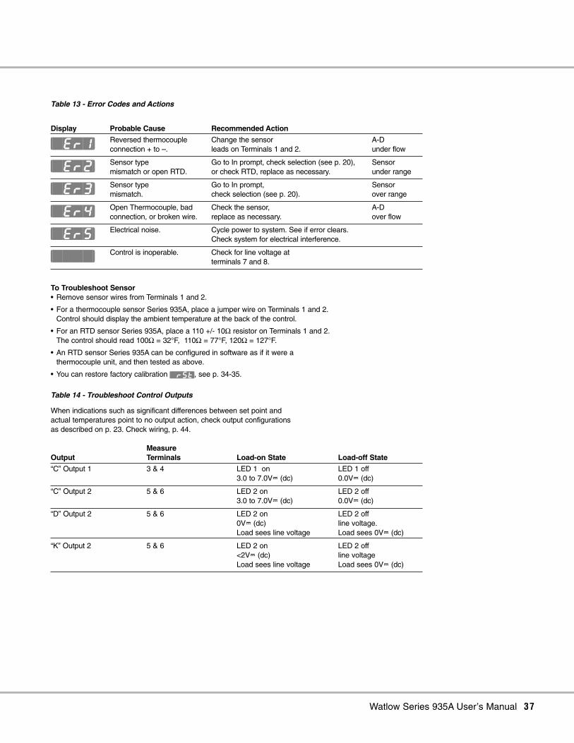
To Troubleshoot Sensor• Remove sensor wires from Terminals 1 and 2.
• For a thermocouple sensor Series 935A, place a jumper wire on Terminals 1 and 2.Control should display the ambient temperature at the back of the control.
• For an RTD sensor Series 935A, place a 110 +/- 10Ω resistor on Terminals 1 and 2.The control should read 100Ω = 32°F, 110Ω = 77°F, 120Ω = 127°F.
• An RTD sensor Series 935A can be configured in software as if it were a thermocouple unit, and then tested as above.
• You can restore factory calibration [`rST], see p. 34-35.
Table 13 - Error Codes and Actions
Display Probable Cause Recommended Action
Reversed thermocouple Change the sensor A-Dconnection + to –. leads on Terminals 1 and 2. under flow
Sensor type Go to In prompt, check selection (see p. 20), Sensormismatch or open RTD. or check RTD, replace as necessary. under range
Sensor type Go to In prompt, Sensormismatch. check selection (see p. 20). over range
Open Thermocouple, bad Check the sensor, A-Dconnection, or broken wire. replace as necessary. over flow
Electrical noise. Cycle power to system. See if error clears.Check system for electrical interference.
Control is inoperable. Check for line voltage at terminals 7 and 8.
Table 14 - Troubleshoot Control Outputs
When indications such as significant differences between set point and actual temperatures point to no output action, check output configurations as described on p. 23. Check wiring, p. 44.
Measure Output Terminals Load-on State Load-off State
“C” Output 1 3 & 4 LED 1 on LED 1 off3.0 to 7.0VÎ (dc) 0.0VÎ (dc)
“C” Output 2 5 & 6 LED 2 on LED 2 off3.0 to 7.0VÎ (dc) 0.0VÎ (dc)
“D” Output 2 5 & 6 LED 2 on LED 2 off0VÎ (dc) line voltage.Load sees line voltage Load sees 0VÎ (dc)
“K” Output 2 5 & 6 LED 2 on LED 2 off<2VÎ (dc) line voltageLoad sees line voltage Load sees 0VÎ (dc)
[`Er1]
[`Er2]
[`Er3]
[`Er4]
[`Er5]
[````]
38 Watlow Series 935A User’s Manual
Mounting
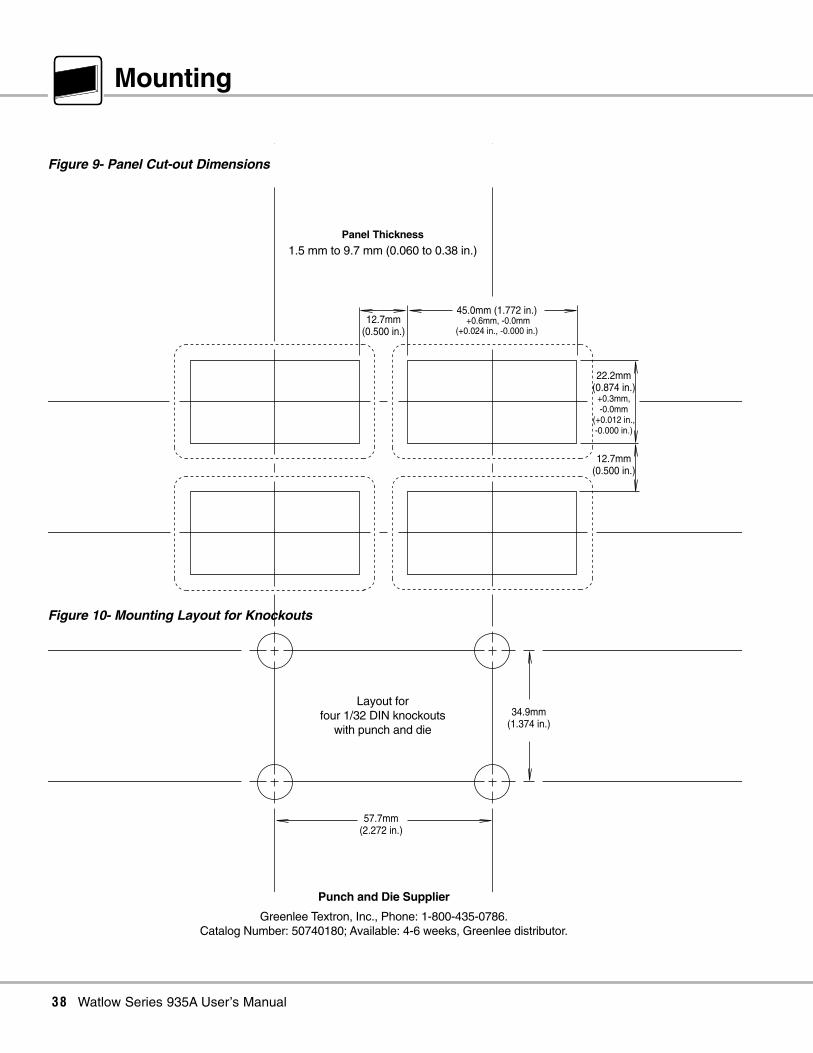
22.2mm(0.874 in.)
+0.3mm,-0.0mm
(+0.012 in.,-0.000 in.)
12.7mm(0.500 in.)
12.7mm(0.500 in.)
57.7mm(2.272 in.)
34.9mm(1.374 in.)
45.0mm (1.772 in.)
(+0.024 in., -0.000 in.)+0.6mm, -0.0mm
Layout forfour 1/32 DIN knockouts
with punch and die
Figure 9- Panel Cut-out Dimensions
Figure 10- Mounting Layout for Knockouts
Panel Thickness
1.5 mm to 9.7 mm (0.060 to 0.38 in.)
Punch and Die Supplier
Greenlee Textron, Inc., Phone: 1-800-435-0786.Catalog Number: 50740180; Available: 4-6 weeks, Greenlee distributor.
Watlow Series 935A User’s Manual 39
Dimensions
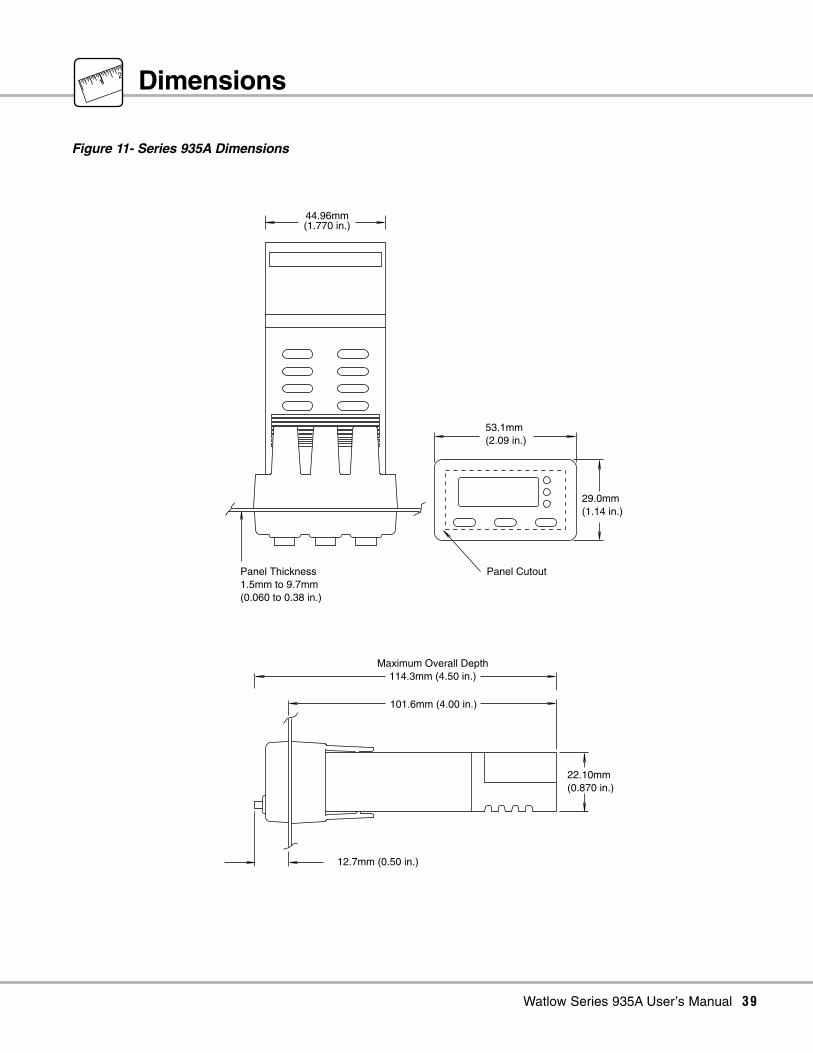
Figure 11- Series 935A Dimensions
53.1mm (2.09 in.)
29.0mm(1.14 in.)
Panel Cutout
44.96mm
101.6mm (4.00 in.)
12.7mm (0.50 in.)
Maximum Overall Depth114.3mm (4.50 in.)
Panel Thickness1.5mm to 9.7mm(0.060 to 0.38 in.)
22.10mm(0.870 in.)
(1.770 in.)
12

40 Watlow Series 935A User’s Manual
Installation Procedure
1. Make a panel cutout using the dimensions in Figure 9, p.38.
2. Insert the 935A into the cutout. Check to see that the gasketis not twisted. Make sure the rounded side of the D-shapedexternal case gasket faces the panel surface, and the gasket is fully seated in its bezel channel. See Figure 12.
3. While pressing the bezel firmly against the panel, slide themounting collar over the back of the control. The tabs on thecollar must line up with the mounting ridges on the case forsecure installation. See Figure 12 again.
4. Slide the collar firmly against the back of the panel, getting itas tight as possible. Make sure you cannot move the casewithin the cutout, if you can, you do not have a IP65/NEMA4X seal!
5. Make sure you have a tight seal. Use your thumb to lock thetabs into place while pressing the case from side to side.Don’t be afraid to apply enough pressure to install the con-trol. The tabs on each side of the collar have teeth whichlatch into the ridges. See Figure 12. Each tooth is staggeredat a different depth (from the front) so only one of the tabson each side is ever locked into the ridges at any time.
6. Look at Figure 13; you see that the tabs on one side of thecollar correspond with those on the opposite side. Be sureonly the two corresponding tabs are locked in the ridges atthe same time. If the matching tabs are not holding thecase, no IP65/NEMA 4X seal exists. Make a visual check,or use your finger nail to pull out on each tab. The space be-tween the bezel and panel must be 0 to 0.48 mm (0 to0.019 in.).
Collar Removal
Slide a thin, wide tool (putty knife) under all three mounting tabs,top then bottom, while pushing forward on the back of the case.
Figure 12- Mounting, Case Top View and CollarCross Section.
Figure 13- Case Rear View and IP65/NEMA 4X SealExample
NOTE: To guarantee a proper IP65/NEMA 4X seal, makesure the gasket between the panel and the rim of the caseis not twisted and is seated properly. Press firmly.
NOTE: Make sure the rounded side of the D-shapedexternal case gasket faces the panel surface, and thegasket is fully seated in its bezel channel. See Figure 12.
0 to 0.483 mm space (0 to 0.019 in.)
Bezel Panel
External Gasket
Mounting Collar
Ridges
Teeth
Tabs

Figure 14- Terminal Block Removal Procedure
1. Press in on sides of cover to release the terminal cover hooks.
2. Move your grip rearward slightly, then lift the terminal cover straight up.
Watlow Series 935A User’s Manual 41
Terminal Block Removal

42 Watlow Series 935A User’s Manual
Wiring a 935A
Figure 15 - Wiring the Series 935A
∫WARNING: All electrical wiring and fusing must conform to local and national electric codes. Contact local authorities forfurther information. Failure to comply with electric codes could result in injury or death, or damage to property.
çCAUTION: Using grounded thermocouples with non-isolated output switching devices could introduce ground loops intothe control system, and possibly damage the controller and product.
NOTE: Torque terminals to 1.36 Nm (12 in lbs).
Low Voltage
S2–1
S1+2
–3
+4 5 6 7 8
OT1IN OT2 POWER24-28
VOLTS
+ -
High Voltage
S2–1
S1+2
–3
+4 5 6 7 8
OT1IN OT2 POWER100-240VOLTS
Remote Set Point Input
S2–1
S1+2
–3
+4 5 6 7 8
OT1IN OT2 POWER
S2–1
S1+2
–3
+4 5 6 7 8
OT1IN OT2 POWER
2-wire
3-wireS3
Thermocouple Input
S2–1
S1+2
–3
+4 5 6 7 8
OT1IN OT2 POWER
Power Wiring Input Wiring

Watlow Series 935A User’s Manual 43
∫WARNING: All electrical wiring and fusing must conform to local and national electric codes. Contact local authorities forfurther information. Failure to comply with electric codes could result in injury or death, or damage to property.
çCAUTION: Failure to install a 60 to 70Ω, 0.5w resistor across the customer-supplied Front Panel Lock switch will cause thepanel to lock out even when the switch is open. Injury to personnel, or damage to equipment or property could result.
∫WARNING: When Output 1 is a Front Panel Lock [`Ot1] = [`FPL], the output is energized! Do not connect a power switchingdevice to Output 1; injury or death, or damage to equipment or property could result.
NOTE: Switching inductive loads (relay coils, solenoids, etc.) with the mechanical relay or solid-state relay output optionsrequires using an R.C. suppressor. Watlow carries the R.C. suppressor Quencharc brand name, which is a trademark ofITW Pakron. Watlow Part No. 0804-0147-0000.
Output 1; Front Panel Lock
S2–1
S1+2
–3
+4 5 6 7 8
OT1IN OT2 POWER
60 to 70Ω, 0.5w resistor
Output 2; Solid State Relay; "K"
S2–1
S1+2
–3
+4 5 6 7 8
OT1IN OT2 POWER
Output 2; Electromechanical Relay; "D"
S2–1
S1+2
–3
+4 5 6 7 8
OT1IN OT2 Power
Output 2; Switched DC; "C"
S2–1
S1+2
–3
+4
–5
+6 7 8
OT1IN OT2 POWER
Internal Circuitry
+5.7 to 8V
Current Limit60mA
Output 1; Switched DC; "C"
S2–1
S1+2
–3
+4 5 6 7 8
OT1IN OT2 POWER
Internal Circuitry
+5.7 to 8V
Current Limit60mA
Output 2 WiringOutput 1 Wiring
See Caution

44 Watlow Series 935A User’s Manual
System Wiring Examples
Figure 16 - Series 935A System Wiring Examples
∫WARNING: All electrical wiring and fusing must conform to local and national electric codes. Contact local authorities forfurther information. Failure to comply with electric codes could result in injury or death, or damage to property.
çCAUTION: Using grounded thermocouples with non-isolated output switching devices could introduce ground loops intothe control system, and possibly damage the grounder and product.
Coil
1 2
Hightemperature light
Heater
Limit SensorProcess Sensor
High LimitMechanicalContactor
Earth Ground
L1120VÅ (ac)
L2
Fus
e
S2–1
S1+2
–3
+4 5 6 7 8
OT1IN OT2 POWER100-240VOLTS
Series 935 935A-1CD0-000G
DA10-24C0-0000DIN-a-mite®
+
3 4
L1
L2
–
10 11 12 13 14 15 16 17
21 3 4 5 6 7 8 9
NOC NC
Series 146limit control
146E-1601-1000
ResetOptionalNormally
OpenMomentary
Switch
5
6
Watlow Series 935A User’s Manual 45
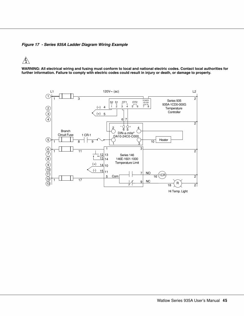
Figure 17 - Series 935A Ladder Diagram Wiring Example
∫WARNING: All electrical wiring and fusing must conform to local and national electric codes. Contact local authorities forfurther information. Failure to comply with electric codes could result in injury or death, or damage to property.
5
S2–1
S1+2
–3
+4 5 6 7 8
OT1 OT21 3
120VÅ (ac)L1
2
L2
1
1
1
11
17
1314
10
11
(+)
(-)
1
5
3
7
9
2
2
2
2
16
18R
1CR
Series 146146E-1601-1000Temperature Limit
108 9
1 CR-1
Heater
BranchCircuit Fuse
Hi Temp. Light
1
2
3
4
5
6
7
8
9
1011
12
13
4(–)
(+)
POWER100-240VOLTS
Series 935935A-1CD0-000G
Temperature Controller
2
1 3
4
DA10-24C0-C000DIN-a-mite®
+–
ComNO
NC
56
6 7
1213
14
15

46 Watlow Series 935A User’s Manual
Glossary
Alarm
A condition, generated by the controller, indicating that the pro-cess has exceeded or fallen below the set or limit point.
Alarm HysteresisA change in the process variable required to re-energize thealarm output.
Ambient TemperatureTemperature surrounding the components of a thermal system.
Auto-tuneAutomatically sets PID values to fit a particular thermal system.
Bumpless TransferWhen transferring from auto to manual operation, the controloutput(s) will maintain the same output level.
CalibrationAdjusting an instrument to a known value.
Configuration MenuThe second software sub menu of the Series 935A OperationsMenu; provides a location to set inputs, ranges, output types,alarm type, timer function, failure mode, and lockout types.
Control ModeThe method of control, i.e. ON/OFF, time proportioning, PI, PIDor manual.
Cycle TimeTime required for a control to complete one ON through OFFcycle.
Dead BandAdjusts the effective cool set point above the primary set pointby the dead band value in degrees. In cool/heat applications,dead band prevents continuous cool output action by creating abuffer between heating and cooling output action.
Delay OFFA Series 935A timer output (Output 2) choice that turns the out-put OFF at the end of the countdown timer time.
Delay ONA Series 935A timer output (Output 2) choice that turns the out-put ON at the end of the countdown timer time.
DerivativeLimits the rate of change of the process to eliminate overshoot inslow or lagging loads (de=ra).
Deviation AlarmAn offset value which tracks the set point. Process changes be-yond this value register an alarm condition.
DIN-a-mite®Watlow family of DIN rail-mounted SCR power controllers.
DroopThe difference between the set point and actual values once thesystem stabilizes.
HysteresisA change in the process variable required to re-energize thecontrol or alarm output.
Idle Set PointDesired control value before and after timing period.
IntegralAccumulates error to eliminate offset or droop (It=1/re).
Local Set PointPrimary set point, not remote.
ON/OFFControl by turning the output full ON until set point is reached,and then turning OFF until the process error exceeds the hys-teresis.
Operations MenuSeries 935A software menu; provides a location to start auto-tune, set alarm points, set countdown time, choose an idle ornormal set point type, choose a local or remote set point input,and to go to the PID or Configuration Menus.
OvershootThe amount a process variable exceeds set point before stabiliz-ing.
Percent Power ControlOpen loop control with output power set at a particular level.
PID(Proportional, Integral, Derivative). A control mode: proportionalaction sets the system, integral reduces droop, derivative re-duces overshoot and undershoot.
PID MenuThe first software sub menu of the Series 935A OperationsMenu; provides a location to manually set values for proportionalband, hysteresis, cycle time, integral, derivative, and calibrationoffset.
Process AlarmA fixed value independent of set point. Process changes beyondthis value register an alarm condition.
Process ErrorThe difference between the set point and the actual process.
ProportionalOutput effort proportional to the error from set point. If the pro-portional band is 20° and the process is 10° below set point, theheat proportioned effort is 50%. The lower the Pb value, thehigher the gain.
Proportional BandA range in which a control’s proportioning function is active (SeePID).
RangeThe area between two limits in which a quantity or value is mea-sured. Usually expressed in terms of lower and upper limits.

Watlow Series 935A User’s Manual 47
Ready AcknowledgeA Series 935A countdown timer start choice that pre-initiates thetimer with a down key press, and then starts it with a SET presswhen the actual temperature is within the Ready
Ready BandThermal area above and below primary set point in which thetimer will count down.
Relay, ElectromechanicalA power switching device that completes or interrupts a circuit byphysically moving electrical contacts. Not recommended for PIDcontrol.
Remote Set PointA 0-5VÎ (dc) input from another controller or other source.
RTDResistive Temperature Detector. A sensor whose resistance in-creases with increasing temperature.Set PointThe desired process value programmed into a control.
SignalAny electrical transmittance that conveys information.
Signal OFFA Series 935 timer output (Output 2) choice that toggles the out-put OFF, then ON at the end of the countdown timer cycle for aperiod equal to the signal time.
Signal ONA Series 935 timer output (Output 2) choice that toggles the out-put ON, then OFF at the end of the countdown timer cycle for aperiod equal to the signal time.
Signal TimeTime duration the timer output will turn ON or OFF after a com-plete timing period.
SCRSilicon controlled rectifier. A solid state device, or thyristor, with nomoving parts, that is used in pairs to control AC voltages withinone cycle. SCRs control voltage from a power source to the loadby burst firing (also called zero-cross firing) or phase angle firing.
SSRSolid State Relay. A solid state switching device that switchescurrent ON and OFF. It has no moving parts.
Thermal SystemA regulated environment consisting of a heat source, heat trans-fer medium, sensing device, a control instrument, and a redun-dant control device (limit).
ThermocoupleA temperature sensing device made by joining two dissimilar met-als. This junction produces an electrical voltage in proportion tothe difference in temperature between the hot junction and leadwire connection to the sensing device (cold junction).
UndershootThe amount a process variable falls below set point before stabi-lizing.

48 Watlow Series 935A User’s Manual
Index
AAuto-tune [`Aut] 10, 32Alarms
Alarm High [`AhI] 10, 24Alarm Low [`ALO] 10, 24Alarm Type [AltY] 24Clearing Alarms 26, 27Deviation [dEnc] , [dEno] 24Hysteresis [AhYS] 24Latch [`LAt] 24Learning 24Process [Prnc] , [Prno] 24Setting 26Silencing [`SIL] 24
BBumpless Transfer [bPLS] 36
CCalibration 34
Factory Restore [`rST] 34Calibration Offset [`CAL] 13Celsius / Fahrenheit [`C_F] 20Clearing Alarms 26, 27Configuration [CnFG] 16Cycle Time 13
Heat [Ct`h] 13Cool [Ct`c] 13
DDead Band [``db] 13Derivative [``dE] 13Dimensions 38, 39DIN-a-mite® compatibility 44, 50, 51Display Default [dISP] 16, 20
EErrors 8, 37
FFailure Mode [FAIL] 17, 36Front Panel Lock [`FPL] 20, 23
GGlossary 46
HHours/Minutes [thM] 16, 28Hysteresis
Alarm [AhYS] 17, 24Heat [hYSh] 13Cool [hYSc] 13
IIdle [IdLE] 10Idle Set Point Track [trAc] 10Input Range Low [``rL] 20Input Range High [``rh] 20Input Type [``In] 21Integral [`It] 13
KKeys 5
LLatch [`LAt] 17, 24, 27Local / Remote [`L-r] 10Lockout Functions 18
Front Panel [`FPL] 18, 23Security Tag [`tAG] 18Set Point [SLOC] 18
MMinutes/Seconds [tMS] 17, 28Mounting 38
OOperations, Learning 10Ordering Information 51Output 1 Function [`Ot1] 3, 20Output 2 Function [`Ot2] 3, 20
PPID Menu, Learning 12PID Settings, Tweaking 33Proportional Band
Heat [Pb`h] 13Cool [Pb`c] 13
RRemote Set Point [`rSP] 20, 22

Watlow Series 935A User’s Manual 49
SSet Point
Change 7Local [`L-r] 10Lock [SLOC] 18Range High [``rh] 20Range Low [``rL] 20Remote Set Point [`rSP] 22Remote [`L-r] 22
Silencing Alarms 27Software Maps
Easy 9Advanced 55-62
Specifications 50
TTerminal Block Removal 41Timer
Countdown [tMr] 10, 28-31Delay off [dLoF] 17, 28Delay on [dLon] 17, 28Function [tIM] 17, 28Hours/Minutes [thM] 17, 28
Idle [IdLE] 17, 28Minutes/Seconds [tMS] 17, 28Ready Band [`rdY] 17, 28Signal off [SGof] 17, 28Signal on [SGon] 17, 28Signal Time [``St] 17, 28Start Timer [Strt] 17, 28
Immediate [IMd] 17, 28Ready Band [`rDY] 17, 28Ready Band- Acknowledge [rdYA] 17, 28
TuningAuto-tuning 10, 32Manual tuning 32
Troubleshooting 36
WWiring 42-43Wiring Examples 44-45
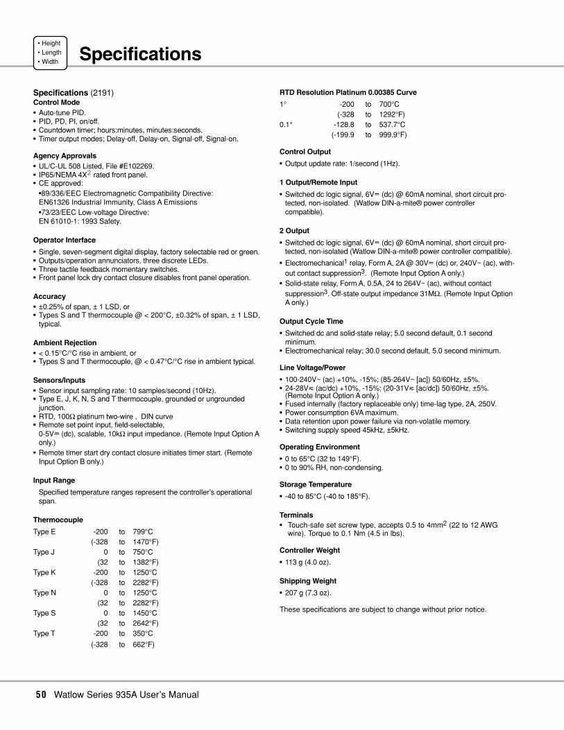
50 Watlow Series 935A User’s Manual
Specifications
Specifications (2191)Control Mode• Auto-tune PID.• PID, PD, PI, on/off.• Countdown timer; hours:minutes, minutes:seconds.• Timer output modes; Delay-off, Delay-on, Signal-off, Signal-on.
Agency Approvals• UL/C-UL 508 Listed, File #E102269.• IP65/NEMA 4X2 rated front panel.• CE approved:
•89/336/EEC Electromagnetic Compatibility Directive:EN61326 Industrial Immunity, Class A Emissions•73/23/EEC Low-voltage Directive:EN 61010-1: 1993 Safety.
Operator Interface
• Single, seven-segment digital display, factory selectable red or green.• Outputs/operation annunciators, three discrete LEDs.• Three tactile feedback momentary switches.• Front panel lock dry contact closure disables front panel operation.
Accuracy• ±0.25% of span, ± 1 LSD, or• Types S and T thermocouple @ < 200°C, ±0.32% of span, ± 1 LSD,
typical.
Ambient Rejection• < 0.15°C/°C rise in ambient, or• Types S and T thermocouple, @ < 0.47°C/°C rise in ambient typical.
Sensors/Inputs• Sensor input sampling rate: 10 samples/second (10Hz).• Type E, J, K, N, S and T thermocouple, grounded or ungrounded
junction.• RTD, 100Ω platinum two-wire , DIN curve• Remote set point input, field-selectable,
0-5VÎ (dc), scalable, 10kΩ input impedance. (Remote Input Option Aonly.)
• Remote timer start dry contact closure initiates timer start. (RemoteInput Option B only.)
Input Range
Specified temperature ranges represent the controller’s operationalspan.
Thermocouple
Type E -200 to 799°C(-328 to 1470°F)
Type J 0 to 750°C(32 to 1382°F)
Type K -200 to 1250°C(-328 to 2282°F)
Type N 0 to 1250°C(32 to 2282°F)
Type S 0 to 1450°C(32 to 2642°F)
Type T -200 to 350°C
(-328 to 662°F)
RTD Resolution Platinum 0.00385 Curve
1° -200 to 700°C(-328 to 1292°F)
0.1° -128.8 to 537.7°C(-199.9 to 999.9°F)
Control Output
• Output update rate: 1/second (1Hz).
1 Output/Remote Input
• Switched dc logic signal, 6VÎ (dc) @ 60mA nominal, short circuit pro-tected, non-isolated. (Watlow DIN-a-mite® power controllercompatible).
2 Output
• Switched dc logic signal, 6VÎ (dc) @ 60mA nominal, short circuit pro-tected, non-isolated (Watlow DIN-a-mite® power controller compatible).
• Electromechanical1 relay, Form A, 2A @ 30VÎ (dc) or, 240V~ (ac), with-out contact suppression3. (Remote Input Option A only.)
• Solid-state relay, Form A, 0.5A, 24 to 264V~ (ac), without contactsuppression3. Off-state output impedance 31MΩ. (Remote Input OptionA only.)
Output Cycle Time
• Switched dc and solid-state relay; 5.0 second default, 0.1 secondminimum.
• Electromechanical relay; 30.0 second default, 5.0 second minimum.
Line Voltage/Power
• 100-240V~ (ac) +10%, -15%; (85-264V~ [ac]) 50/60Hz, ±5%.• 24-28Vı (ac/dc) +10%, -15%; (20-31Vı [ac/dc]) 50/60Hz, ±5%.
(Remote Input Option A only.)• Fused internally (factory replaceable only) time-lag type, 2A, 250V.• Power consumption 6VA maximum.• Data retention upon power failure via non-volatile memory.• Switching supply speed 45kHz, ±5kHz.
Operating Environment
• 0 to 65°C (32 to 149°F).• 0 to 90% RH, non-condensing.
Storage Temperature
• -40 to 85°C (-40 to 185°F).
Terminals• Touch-safe set screw type, accepts 0.5 to 4mm2 (22 to 12 AWG
wire). Torque to 0.1 Nm (4.5 in lbs).
Controller Weight
• 113 g (4.0 oz).
Shipping Weight
• 207 g (7.3 oz).
These specifications are subject to change without prior notice.

Watlow Series 935A User’s Manual 51
Ordering a 935A
Ordering Information (2192)
Single thermocouple or RTD (DIN) input, dual output, singlie display temperature control with time function and four digit display
Remote InputsA = Remote set point input, or front panel lock input in place of output #1B = Separate input for remote timer start, or front panel lock
Output 1/Remote InputC = Switched dc, logic signal, non-isolated; (Watlow DIN-a-mite® power
controller compatible)(Optionally used for remote set point input; or front panel lock input for Remote Input A option only.)
Output 2C = Switched dc, logic signal, non-isolated (Watlow DIN-a-mite® power
controller compatible)D = Electromechanical relay 1, Form A, 2A, 240VÅ (ac), without contact
suppression 3 (Remote Input A option only.)K = Solid-state relay, 0.5A, 24-264VÅ (ac), without contact suppression 3
(Remote Input A option only.)
Power Supply0 = 100 to 240VÅ (ac) nominal (high voltage)1 = 24 to 28V‡ (ac/dc) nominal (low voltage)(Remote Input A option only.)
Custom Options00 = NoneAA = No Watlow logoXX = Custom label or parameters
DisplayR = Red displaysG = Green displays
Table 15 - Input Range Information
1 Electromechanical relays are warranted for 100,000 closures only. Solid-state switching devices are recommended for applications requiringfast cycle times or extended service life.
2 To effect IP65 (NEMA 4X) rating requires a minimum mounting panel thickness of 1.5mm (0.06 inch) and a surface finish not rougher than0.000812 mm (0.000032 in.).
3 When using this output to drive a solenoid, MDR or electromechanical relay (contactor), protect output with a Quencharc®. Order code number0804-0147-0000. Refer to owner's manual for wiring information. Quencharc® is a registered trademark of ITW Paktron.
J t/c: 0 to 750°C or 32 to 1382°FK t/c: -200 to 1250°C or -328 to 2282°FT t/c: -200 to 350°C or -328 to 662°FN t/c: 0 to 1250°C or 32 to 2282°FS t/c: 0 to 1450°C or 32 to 2642°FE t/c: -200 to 799°C or -328 to 1470°F1° RTD (DIN): -200 to 700°C or -328 to 1292°F0.1° RTD: -99.9 to 700.0°C or -99.9 to 999.9°F
935 -1C - 0

52 Watlow Series 935A User’s Manual
Declaration of ConformitySeries 935
WATLOW Winona, Inc.1241 Bundy BoulevardWinona, Minnesota 55987 USA
Declares that the following product: EnglishDesignation: Series 935Model Numbers: 935(A or B) – 1C(C, D or K)(0 or 1) – (Any four
letters or numbers)Classification: Temperature control, Installation Category II,
Pollution degree IIRated Voltage: 100 to 240 V~ (ac) or 24 to 28 V ‡ (ac or dc)Rated Frequency: 50 or 60 HzRated Power Consumption: 6 VA maximum
Meets the essential requirements of the following European Union Directives byusing the relevant standards show below to indicate compliance.
89/336/EEC Electromagnetic Compatibility DirectiveEN 61326:1997 With A1:1998 – Electrical equipment for measurement, controland laboratory use – EMC requirements (Industrial Immunity, Class AEmissions).EN 61000-4-2:1996 With A1, 1998 – Electrostatic Discharge ImmunityEN 61000-4-3:1997 – Radiated Field ImmunityEN 61000-4-4:1995 – Electrical Fast-Transient / Burst ImmunityEN 61000-4-5:1995 With A1, 1996 – Surge ImmunityEN 61000-4-6:1996 – Conducted ImmunityEN 61000-4-11:1994 Voltage Dips, Short Interruptions and Voltage Variations ImmunityEN 61000-3-2:1995 With A1-3:1999 – Harmonic Current EmissionsEN 61000-3-3:1995 With A1:1998 – Voltage Fluctuations and Flicker
73/23/EEC Low-Voltage DirectiveEN 61010-1:1993 With A1:1995 Safety Requirements of electrical equipmentfor measurement, control and laboratory use. Part 1: General requirements
déclare que le produit suivant : FrançaisDésignation : Série 935Numéros de modèle : 935(A ou B) – 1C(C, D ou K)(0 ou 1) – (N’importe
quelle combinaison de quatre lettres ou chiffres)Classification : Régulation de température, Catégorie d’installation II,
Degré de pollution IITension nominale : 100 à 240 V~ (c.a) ou 24 à 28 V ‡ (c.a ou c.c)Fréquence nominale : 50 ou 60 HzConsommation d’alimentation nominale: 6 VA maximum
Répond aux normes essentielles des directives suivantes de l'Union européenneen utilisant les standards normalisés ci-dessous qui expliquent les normesauxquelles répondre :
Directive 89/336/CEE sur la compatibilité électromagnétiqueEN 61326:1997 avec A1 :1998 – Matériel électrique destiné à l’étalonnage, aucontrôle et à l’utilisation en laboratoire – Exigences CEM (Immunitéindustrielle, Émissions de catégorie A).EN 61000-4-2:1996 Avec A1, 1998 – Immunité aux décharges électrostatiquesEN 61000-4-3:1997 – Immunité aux champs de radiationEN 61000-4-4:1995 – Immunité contre les surtensions électriques rapides/ RafaleEN 61000-4-5:1995 avec A1, 1996 – Immunité contre les surtensionsEN 61000-4-6:1996 – Immunité conduiteEN 61000-4-11:1994 Immunité contre les écarts de tension, interruptions courteset variations de tensionEN 61000-3-2:1995 avec A1-3 :1999 – Emissions de courant harmoniquesEN 61000-3-3:1995 avec A1 :1998 – Fluctuations et vacillements de tension
Directive 73/23/CEE sur les basses tensionsEN 61010-1:1993 avec A1 :1995 Normes de sécurité du matériel électriquepour la mesure, le contrôle et l’utilisation en laboratoire. 1ère partie :Conditions générales
Erklärt, dass das folgende Produkt: DeutschBezeichnung: Serie 935Modell-Nummern: 935(A oder B) – 1C(C, D oder K)(0 oder 1) –
(Beliebige vier Ziffern oder Buchstaben)Klassifikation: Temperaturregler, Installationskategorie II,
Verschmutzungsgrad IINennspannung: 100 bis 240 V~ (ac) oder 24 bis 28 V ‡ (AC oder DC)Nennfrequenz: 50/60 Hz.Nennstromverbrauch: 6 VA max.
Erfüllt die wichtigsten Normen der folgenden Anweisung(en) der EuropäischenUnion unter Verwendung des wichtigsten Abschnitts bzw. der wichtigstenAbschnitte die unten zur Befolgung aufgezeigt werden.
89/336/EEC Elektromagnetische KompatibilitätsrichtlinieEN 61326:1997 mit A1:1998 – Elektrisches Gerät für Messung, Kontrolle und Laborgebrauch – EMV-Anforderungen (Störfestigkeit Industriebereich,Klasse A Emissionen)EN 61000-4-2:1996 mit A1, 1998 – Störfestigkeit gegen elektronische Entladung EN 61000-4-3:1997 – Störfestigkeit gegen StrahlungsfelderEN 61000-4-4:1995 – Störfestigkeit gegen schnelle Stöße/BurstEN 61000-4-5:1995 mit A1, 1996 – Störfestigkeit gegen ÜberspannungEN 61000-4-6:1996 – Geleitete StörfestigkeitEN 61000-4-11:1994 Störfestigkeit gegen Spannungsabfall, kurze Unterbrechungen und SpannungsschwankungenEN 61000-3-2:1995 mit A1-3:1999 – Harmonische StromemissionenEN 61000-3-3:1995 mit A1:1998 – Spannungsfluktationen und Flimmern
73/23/EEC NiederspannungsrichtlinieEN 61010-1:1993 mit A1:1995 Sicherheitsanforderungen für elektrische Geräte für Messungen, Kontrolle und Laborgebrauch. Teil 1: AllgemeineAnforderungen
Declara que el producto siguiente: EspañolDesignación: Serie 935Números de modelo: 935(A o B) – 1C(C, D o K)(0 o 1) – (Cualesquiera
cuatro letras o números)Clasificación: Control de temperatura, Categoría de instalación II,
Grado de contaminación IIVoltaje nominal 100 a 240 V~ (CA) o 24 a 28 V ‡(CA o CD)Frecuencia nominal: 50 o 60 HzConsumo de energía nominal: 6 VA máximo
Cumple con los requisitos esenciales de las siguientes Directrices de la UniónEuropea mediante el uso de las normas aplicables que se muestran a continuaciónpara indicar su conformidad.
89/336/EEC Directriz de compatibilidad electromagnéticaEN 61326:1997 CON A1:1998.– Equipo eléctrico para medición, control y usoen laboratorio – Requisitos EMC (Inmunidad industrial, Emisiones Clase A).EN 61000-4-2:1996 con A1, 1988 – Inmunidad a descarga electrostáticaEN 61000-4-3:1997 – Inmunidad a campo radiadoEN 61000-4-4:1995 – Inmunidad a incremento repentino/rápidas fluctuaciones eléctricas transitoriasEN 61000-4-5:1995 con A1, 1996 – Inmunidad a picos de voltaje o corrienteEN 61000-4-6:1996 – Inmunidad por conducciónEN 61000-4-11:1994 Inmunidad a caídas de voltaje, variaciones y pequeñas interrupciones de voltajeEN 61000-3-2:1995 con A1-3:1999 – Emisiones de corriente armónicaEN 61000-3-3:1995 con A1:1998 – Fluctuaciones de voltaje y centelleo.
73/23/EEC Directriz de bajo voltajeEN 61010-1:1993 con A1:1995 Requisitos de seguridad de equipo eléctricpara medición, control y uso en laboratorio. Parte 1: Requisitos generales
(2193)
Jim Boigenzahn Winona, Minnesota, USAName of Authorized Representative Place of Issue
General Manager August, 2001Title of Authorized Representative Date of Issue
________________________________________Signature of Authorized Representative

Watlow Series 935A User’s Manual 53
Notes

54 Watlow Series 935A User’s Manual
Notes

Watlow Series 935A User’s Manual 55
935A Software MapO
per
atio
ns
Men
u
Prompt Range Default Hidden if * Your Settings
*NOTE:
All prompts, except[``SP] and [`tAG],are hidden if [`Ot1] =[`FPL].
[`tA9] = [`O``];
or if
[`Ot2] ≠ [thM] or[tMs]
[trAc][trAc] [``rL]
[``rh]
Choose an idle SetPoint. Trac is an Idle SetPoint equal to thePrimary Set Point; orselect a value betweenInput Type Range Lowand Input Type RangeHigh.
[idLE]
Idle Set Point Type
[`tA9] = [`O``];
or if
[`Ot2] ≠ [thM] or[tMs]
0[0000]
Select a countdown timevalue, adjustablebetween 00:00 and99:59 hrs:mins ormin:sec.
[tMr]
Countdown Timer
[`tA9] = [`O``];
or if
[`Ot1] and [`Ot2] ≠[ALM]
Type J Range High[`RL0]
Select a value,adjustable betweenAlarm Low and RangeHigh.
[`Ah1]
Alarm High
[`tA9] = [`O``];
or if
[`Ot1] and [`Ot2] ≠[ALM]
Type J Range Low[`Ah1]
Select a value,adjustable betweenRange Low and AlarmHigh.
[`ALO]
Alarm Low
[`tA9] = [```A]no[``no] [`YES]
Choose YES to Auto-tune the 935A.
[`Aut]
Auto-tune
Appears always75°F or 23°C[``rL] [``rh]
Select a value,adjustable between InputType Range Low andInput Type Range High.
[``SP]
Primary Set Point
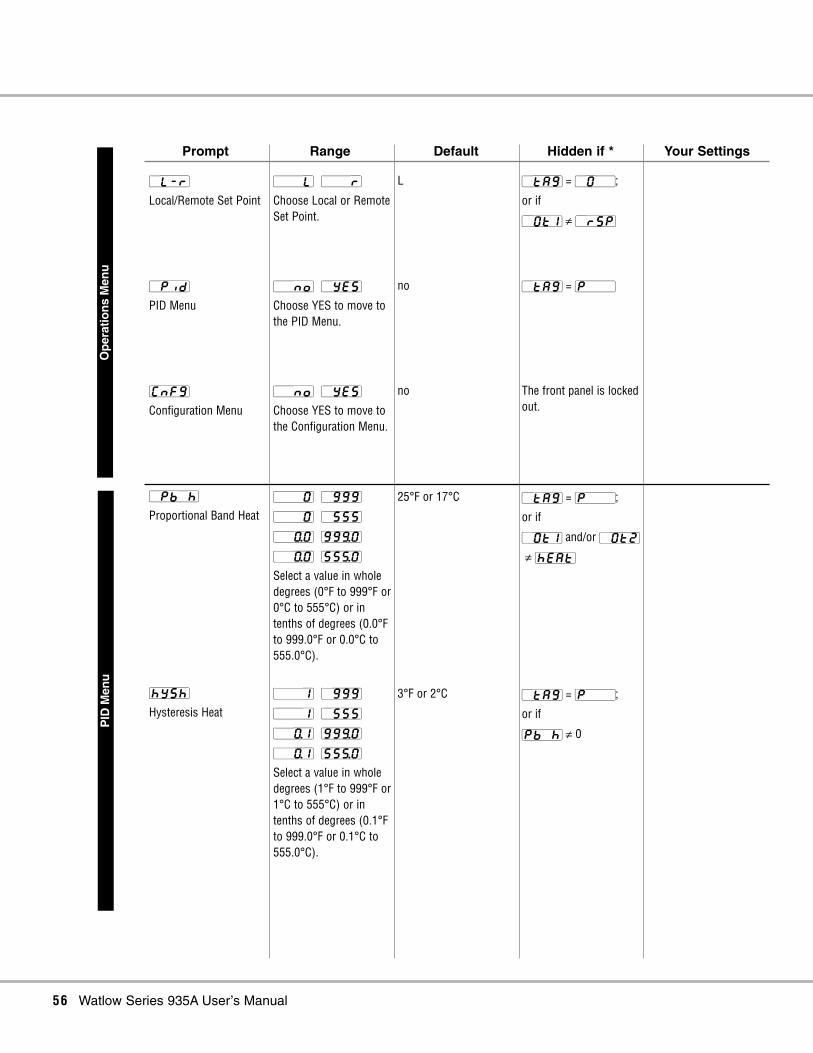
56 Watlow Series 935A User’s Manual
Op
erat
ion
s M
enu
Prompt Range Default Hidden if * Your Settings
[`tA9] = [P```];
or if
[Pb`h] ≠ 0
3°F or 2°C[```1] [`999]
[```1] [`555]
[``)1] [99(0]
[``)1] [55%0]
Select a value in wholedegrees (1°F to 999°F or1°C to 555°C) or intenths of degrees (0.1°Fto 999.0°F or 0.1°C to555.0°C).
[hYSh]
Hysteresis Heat
[`tA9] = [P```];
or if
[`Ot1] and/or [`Ot2]
≠ [hEAt]
25°F or 17°C[```0] [`999]
[```0] [`555]
[``)0] [99(0]
[``)0] [55%0]
Select a value in wholedegrees (0°F to 999°F or0°C to 555°C) or intenths of degrees (0.0°Fto 999.0°F or 0.0°C to555.0°C).
[`Pb`h]
Proportional Band Heat
The front panel is lockedout.
no[``no] [`YES]
Choose YES to move tothe Configuration Menu.
[CnFg]
Configuration Menu
[`tA9] = [P```]no[``no] [`YES]
Choose YES to move tothe PID Menu.
[`Pid]
PID Menu
[`tA9] = [`O``];
or if
[`Ot1] ≠ [`rSP]
L[```L] [```r]
Choose Local or RemoteSet Point.
[`L-r]
Local/Remote Set Point
PID
Men
u

Watlow Series 935A User’s Manual 57
PID
Men
u
Prompt Range Default Hidden if * Your Settings
[`tA9] = [P```];
or if
[Pb`c] ≠ 0
3°F or 2°C[```1] [`999]
[```1] [`555]
[``)1] [99(0]
[``)1] [55%0]
Select a value in wholedegrees (1°F to 999°F or1°C to 555°C) or intenths of degrees (0.1°Fto 999.0°F or 0.1°C to555.0°C).
[hYSc]
Hysteresis Cool
[`tA9] = [P```];
or if
[`Ot1] ≠ [cool]
and/or
[`Ot2] ≠ [cool]
25°F or 17°C[```0] [`999]
[```0] [`555]
[``)0] [99(0]
[``)0] [55%0]
Select a value in wholedegrees (0°F to 999°F or0°C to 555°C) or intenths of degrees (0.0°Fto 999.0°F or 0.0°C to555.0°C).
[Pb`c]
Proportional Band Cool
[`tA9] = [P```];
or if
[`Ot1] = [cool] and
[`Ot2] ≠ [hEAt];
or if
[`Ot1] = [hEAt] and
[`Ot2] ≠ [cool]
0°F or 0°C[```0] [`999]
[```0] [`555]
[``)0] [99(0]
[``)0] [55%0]
Select a value in wholedegrees (0°F to 999°F or0°C to 555°C) or intenths of degrees (0.0°Fto 999.0°F or 0.0°C to555.0°C).
[``db]
Dead Band
[`tA9] = [P```];
or if
[Pb`h] = 0
1.0 second[``)1] [`6)0]
[``%0] [`6)0]
Select a value between0.1 and 60.0 seconds(Solid-State Relay orSwitched DC) or 5.0 and60.0 seconds(ElectromechanicalRelay).
[Ct`h]
Cycle Time Heat

58 Watlow Series 935A User’s Manual
PID
Men
u
Prompt Range Default Hidden if * Your Settings
[`tA9] = [P```]0°F or 0°C[-999] [9999]
[-9(9] [99(9]
Select a value,adjustable between
-999° and 9999°F or Cor -99.9° and 999.9°F orC to eliminate adifference between thedisplayed temperatureand the actualtemperature.
[`CAL]
Calibration Offset
[`tA9] = [P```];
or if
[Pb`h] = 0;
or if
[Pb`h] is hidden; andif [Pb`c] = 0;
or if
[Pb`c] is hidden
0 minutes[`)00] [`(99]
Select a value,adjustable between 0.00and 9.99 minutes.
[``dE]
Derivative Function
[`tA9] = [P```];
or if
[Pb`h] = 0;
or if
[Pb`h] is hidden; andif [Pb`c] = 0;
or if
[Pb`c] is hidden
5.00 minutes/repeat[``)0] [9(99]
Select a value,adjustable between 0.0and 99.99minutes/repeat.
[``It]
Integral Function
[`tA9] = [P```];
or if
[Pb`c] = 0
or if
[Pb`c] is hidden
5.0 seconds[``)1] [`6)0]
[``%0] [`6)0]
Select a value between0.1 and 60.0 seconds(Solid-State Relay orSwitched DC) or 5.0 and60.0 seconds(ElectromechanicalRelay).
[Ct`c]
Cycle Time Cool

Watlow Series 935A User’s Manual 59
Co
nfig
ura
tion
Men
u
Prompt Range Default Hidden if * Your Settings
[`tA9] = [``C`]heat[hEAt] [COOL]
[ALM] [`rSP]
[`FPL] [nonE]
Choose Heat, Cool,Alarm, Remote SetPoint, Front Panel Lockor No output action.
[`Ot1]
Output 1 Function
[`tA9] = [``C`]Type J range high value[``rL] [``In]
Select a value betweenInput Type Range Highand Input Range Low.
[``rh]
Range High
[`tA9] = [``C`]Type J range low value[``In] [``rh]
Select a value betweenInput Type Range Lowand Input Range High.
[``rL]
Range Low
[`tA9] = [``C`]F[``°F] [``°C]
Choose to indicatetemperature in°Fahrenheit or °Celsius.
[`C_F]
Celsius/Fahrenheit
[`tA9] = [``C`]J[```J] J t/c
[```H] K t/c
[```t] T t/c
[```N] N t/c
[```E] E t/c
[```S] S t/c
[`rtd] 1.0°RTD
[`rtd] 0.1°RTD
[``In]
Input Type

60 Watlow Series 935A User’s Manual
Co
nfig
ura
tion
Men
u
Prompt Range Default Hidden if * Your Settings
[`tA9] = [``C`];
or if
[`Ot1] and/or
[`Ot2] ≠ [ALM]
3°F or 2°C[```1] [`999]
[```1] [`555]
[``)1] [99(0]
[``)1] [55%0]
Select a value in wholedegrees (1°F to 999°F or1°C to 555°C) or intenths of degrees (0.1°Fto 999.0°F or 0.1°C to555.0°C).
[AhYS]
Alarm Hysteresis
[`tA9] = [``C`];
or if
[`Ot1] and/or
[`Ot2] ≠ [ALM]
Prnc[Prnc] [Prno]
[dEnc] [dEno]
Choose an alarm type:Process normallyclosed, Processnormally open, Deviationnormally closed orDeviation normally open.
[ALtY]
Alarm Type
[`tA9] = [``C`]Ac[``Ac] [AcSP]
[Act1] [t1Ac]
[t1SP]
Choose the primary (last2 characters) andsecondary (first 2characters) Defaultdisplays. Press ß totoggle to the secondarydisplay for 15 seconds.
[dISP]
Display Default
[`tA9] = [``C`]none[hEAt] [COOL]
[ALM] [`thM]
[tMS] [nonE]
Choose Heat, Cool,Alarm, Timer (Hrs:Min),Timer (Min:Sec) or Nooutput action.
[`Ot2]
Output 2 Function

Watlow Series 935A User’s Manual 61
Co
nfig
ura
tion
Men
u
Prompt Range Default Hidden if * Your Settings
[`tA9] = [``C`];
or if
[`Ot2] ≠ [thM] or[tMS]
0°F or 0°C[```0] [`999]
[```0] [`555]
[``)0] [99(0]
[``)0] [55%0]
If [Strt] = [rdYA] or[`rdy], then select avalue in whole degrees(0°F to 999°F or 0°C to555°C) or in tenths ofdegrees (0.0°F to999.0°F or 0.0°C to555.0°C).
[`rdY]
Timer Ready Band
[`tA9] = [``C`];
or if
[`Ot2] ≠ [thM] or[tMS]
Immediate[IMd] [`rdY]
[rdYA] [PWr]
Choose Immediate,Ready Band, ReadyBand Acknowledge, orPower.
[Strt]
Start Timer Function
[`tA9] = [``C`];
or if
[`Ot2] ≠ [thM] or[tMS]
Delay OFF[dLon] [dLoF]
[SGon] [SGoF]
Choose Delay ON, DelayOFF, Signal ON, or SignalOFF.
[tIM]
Timer Output Function
[`tA9] = [``C`];
or if
[`Ot1] and [`Ot2] ≠[hEAt] or [cooL]
Bumpless[bPLS] [-100]
[`100]
Choose BumplessTransfer or PercentPower.
[FAIL]
Input Failure Mode
[`tA9] = [``C`];
or if
[`Ot1] and/or
[`Ot2] ≠ [ALM]
no[``no] [`YES]
Choose YES for aSilenced Alarm on start-up or silencing duringoperation.
[`SIL]
Alarm Silencing
[`tA9] = [``C`];
or if
[`Ot1] and/or
[`Ot2] ≠ [ALM]
no[``no] [`YES]
Choose YES for aLatching Alarm.
[`LAt]
Alarm Latch

62 Watlow Series 935A User’s Manual
Co
nfig
ura
tion
Men
u
Prompt Range Default Hidden if * Your Settings
Always appearsP[PCOA] [`COA]
[PCO`] [`CO`]
[PC`A] [`C`A]
[PC``] [`C``]
[P`OA] [``OA]
[P`O`] [``O`]
[P`A`] [```A]
[P```] [````]
Choose themenus/functions thatwill not be displayed,and therefore cannot bechanged.
P = PID Menu
C = Configuration Menu(except tag)
O = Operations Menu
(except [CnFg])
A = Auto-tune
[`tA9]
Lockout Tag
[`tA9] = [``C`]no[``no] [`YES]
Choose YES to Lock thePrimary Set Point.
[SLOC]
Set Point Lockout
[`tA9] = [``C`];
or if
[tIM] ≠ [SGon] or[SGof]
00:01[```1] [9( 9]
If [t1M] = [SGon] or[SGof], then select avalue between 00:01 and99:59 min:sec.
[``St]
Signal Time

Watlow Series 935A User’s Manual 63
Notes

64 Watlow Series 935A User’s Manual
Notes

About Watlow WinonaWatlow Winona is a U.S. division of Watlow Electric Manufacturing Company, St. Louis,Missouri, a manufacturer of industrial electric heating products since 1922. Watlowproducts include electric heaters, sensors, controllers and switching devices. The Winonaoperation has been designing solid-state electronic control devices since 1962, and hasearned the reputation as an excellent supplier to original equipment manufacturers. TheseOEMs and end users depend upon Watlow Winona to provide compatibly engineeredcontrols that they can incorporate into their products with confidence. Watlow Winonaresides in a 100,000-square-foot marketing, engineering and manufacturing facility inWinona, Minnesota.
WarrantyThe Watlow Series 935 is warranted to be free of defects in material and workmanship for36 months after delivery to the first purchaser for use, providing that the units have notbeen misapplied. Since Watlow has no control over their use, and sometimes misuse, wecannot guarantee against failure. Watlow's obligations hereunder, at Watlow's option, arelimited to replacement, repair or refund of purchase price, and parts which upon examina-tion prove to be defective within the warranty period specified. This warranty does notapply to damage resulting from transportation, alteration, misuse, or abuse.
Returns• Call or fax your distributor or the nearest Watlow sales office for best information
about returns. (See outside back cover.)
• To return directly to Watlow Winona in the U.S., first call or fax Customer Service fora Return Material Authorization (RMA) number (telephone: +1 (507) 454-5300; fax: +1(507) 452-4507).
• Put the RMA number on the shipping label, along with on a written description of theproblem.
• A restocking charge of 20% of the net price is charged for all standard units returned tostock.

How to Reach Us
Quality andMission Statement:Watlow Winona will be theworld’s best supplier ofsuperior measurement andcontrol products, services,and systems, by exceedingthe expectations of ourcustomers, shareholders,and employees.
Europe:Watlow GmbHIndustriegebiet HeidigLauchwasenstr. 1, Postfach 1165,Kronau 76709 GermanyTelephone: +49 7253-9400 0Fax: +49 7253-9400 44
Watlow France S.A.R.L.Immeuble Somag, 16 Rue Ampère,Cergy Pontoise CEDEX 95307 FranceTelephone: +33 (1) 3073-2425Fax: +33 (1) 3073-2875
Watlow Italy S.R.L.Via Meucci 1420094 Corsico MIItalyTelephone: +39 (02) 4588841Fax: +39 (02) 458-69954
Watlow LimitedRobey Close, Linby Industrial Estate,Linby Nottingham England, NG15 8AATelephone: +44 (0) 115 9640777Fax: +44 (0) 115 9640071
Latin America:Watlow de MéxicoAv. Fundición #5,Col. Parques Industriales,Querétaro, Qro. México CP-76130Telephone: +52 (442) 217-6235Fax: +52 (442) 217-6403
Asia/Pacific:Watlow Australia Pty., Ltd.23 Gladstone Park Drive, Tullamarine, Victoria 3043 Australia Telephone: +61 (39) 335-6449Fax: +61 (39)330-3566
Watlow China, Inc.179, Zhong Shan Xi RoadHong Qiao Cointek Bldg, Fl. 4, Unit PShanghai 200051 ChinaTelephone: +86 (21) 6229-8917Fax: +86 (21) 6228-4654
Watlow Japan Ltd. K.K.Azabu Embassy Heights 106,1-11-12 Akasaka,Minato-ku, Tokyo 107-0052 JapanTelephone: +81 (03) 5403-4688Fax: +81 (03) 5403-4646
Watlow Korea Co., Ltd.Hanil Bldg., 3rd Floor210-5 Yangje-Dong Seocho-GuSeoul, 137-130 KoreaTelephone: +82 (2) 575-9804Fax: +82 (2) 575-9831
Watlow Malaysia Sdn Bhd38B Jalan Tun Dr Awang11900 Bayan LepasPenang MalaysiaTelephone: +60 (4) 641-5977Fax: +60 (4) 641-5979
Watlow Singapore Pte. Ltd.Ayer Rajah Crescent #03-23 Ayer Rajah Industrial EstateSingapore 139949Telephone: +65 773 9488Fax: +65 778 0323
Watlow Electric Taiwan10F-1 No. 189Chi-Shen 2nd Road,Kaohsiung, TaiwanTelephone: +886 (7) 288-5168Fax: +886 (7) 288-5568
TOTAL
3 Year Warranty
CUSTOMERSATISFACTION
Your Authorized Watlow Distributor:


