
xx
HDI PUMP
SERVICE &MAINTENANCE
MANUAL
SERVICE and MAINTENANCE MANUALfor
INTERLUBELUBRICATION SYSTEM
ISSU
E02
/201
1

SAFETYAs with all equipment, all due care must beused when servicing the HDI lubricationsystem.
Throughout this manual there will beinformation provided which requiresspecial attention. This information will bedisplayed under the headings of WARNING,CAUTION, or NOTE.
TABLE OF CONTENTS1. INTRODUCTION 3
2. GENERAL DESCRIPTION 3
3. COMPONENT OPERATION 43.1. Pumping Units 43.1. Pump Operation 4/53.3. Relief Valves 5
4. WIRING 6,7,84.1. Wiring with Controls 64.2. Wiring without Controls 64.3. Alarm Functions 74.4. Remote Alarm 74.5. Low Level 84.6. Pump Connectors 8
5. PROGRAMMING 9
6. PUMP DIMENSIONS 10
7. TECHNICAL DATA 10
8. PUMP FILLING 11
9. TROUBLESHOOTING 12
10. SERVICE PROCEDURES 1310.1. Lid Replacement all Models 1310.2. Reservoir Replacement all Models 1310.3. Paddle Blade Replacement all Models 1310.4. PCB Replacement all Models 1310.5. Pump Element Replacement 13
11. PUMP EXPLODED VIEW (Moulded) 1411.1. Parts List (Moulded) 15
12. PUMP EXPLODED VIEW(Standard 3,6,9 & 15Kg) 16
12.1. Parts List 17
13.HDI PROGRESSIVE SYSTEM EXAMPLES 1813.1. Divider Valves 1913.2. Divider Valve Accessories 19
UK Headquarters:Interlube Systems LtdSt Modwen Road, Parkway Industrial Estate,Plymouth, Devon, England PL6 8LHTel: +44 (0)1752 676000Fax: +44 (0)1752 676001e-mail: [email protected] Site: www.interlubesystems.com
USA Headquarters:Interlube Systems Inc4696 Wadsworth Road, Dayton, Ohio, 45414, USATel: + 1 937 276 4507 Fax: + 1 937 276 4518e-mail: [email protected]
Interlube Systems (Malaysia) Sdn.30, Jalan Appollo U5/189, Bandar Pinggiran Subang Sesyen,40150 Shah Alam, Selangor, Malaysia.Tel: (603) 7845 5377 Fax: (603) 7845 5977Email: [email protected]
3
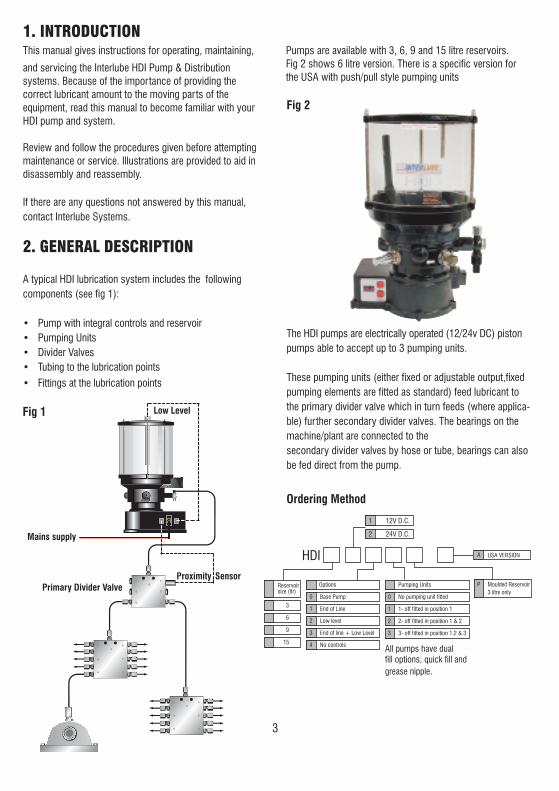
Pumps are available with 3, 6, 9 and 15 litre reservoirs.Fig 2 shows 6 litre version. There is a specific version forthe USA with push/pull style pumping units
The HDI pumps are electrically operated (12/24v DC) pistonpumps able to accept up to 3 pumping units.
These pumping units (either fixed or adjustable output,fixedpumping elements are fitted as standard) feed lubricant tothe primary divider valve which in turn feeds (where applica-ble) further secondary divider valves. The bearings on themachine/plant are connected to thesecondary divider valves by hose or tube, bearings can alsobe fed direct from the pump.
Ordering Method
1. INTRODUCTIONThis manual gives instructions for operating, maintaining,
and servicing the Interlube HDI Pump & Distributionsystems. Because of the importance of providing thecorrect lubricant amount to the moving parts of theequipment, read this manual to become familiar with yourHDI pump and system.
Review and follow the procedures given before attemptingmaintenance or service. Illustrations are provided to aid indisassembly and reassembly.
If there are any questions not answered by this manual,contact Interlube Systems.
2. GENERAL DESCRIPTION
A typical HDI lubrication system includes the followingcomponents (see fig 1):
• Pump with integral controls and reservoir• Pumping Units• Divider Valves• Tubing to the lubrication points
• Fittings at the lubrication points
Fig 1
Fig 2
1 12V D.C.
2 24V D.C.
Options Pumping Units
0 No pumping unit fitted
1 1- off fitted in position 1
2 2- off fitted in position 1 & 2
3 3- off fitted in position 1,2 & 3
0 Base Pump
1 End of Line
2 Low level
3 End of line + Low Level
4 No controls
Reservoirsize (ltr)
3
6
9
15
HDI
P Moulded Reservoir3 litre only
All pumps have dualfill options, quick fill andgrease nipple.
Mains supply
Low Level
Primary Divider ValveProximity Sensor
USA VERSIONA

4
3. COMPONENT OPERATION3.1 HDI Pump OutputsAll HDI Pumps are supplied with one pump element asstandard. Up to three pump elements can be fitted into oneHDI pump
Pumping Unit SparesPump Elements Standard Pump
Spring Return
Element
PU 300-350
PU 400-350
Push Pull Element
PU 300-350-A
PU 400-350-A
The electric motor drives an eccentric cam during thepumps operating time.
Operation
25
13
4
6
Fig 4
Fig 3
The pump element piston sucks the grease from thereservoir and then dispenses an accurate precise amount oflubricant to the connected metering device.
Pump Elements - USA Pumps
5
Pump Output
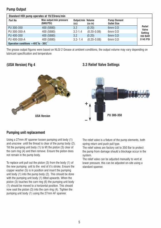
3.3 Relief Valve Settings
Standard HDI pump operates at 19/23revs/minPart No Max output/min pressure
(BAR/PSI)Output/min Volume(cc) (cu in)
Pump ElementOutlet Size
ReliefValve
Setting350 BAR5145 PSI
PU 300-350 400 (5880) 3.2 (0.20) 6mm O.DPU 300-350-A 400 (5880) 3.2-1.4 (0.20-0.08) 6mm O.DPU 400-350 400 (5880) 3.2 (0.20) 6mm O,DPU 400-350-A 400 (5880) 3.2- 1.4 (0.20-0.08) 6mm O.DOperation conditions +40C to - 30C
The grease output figures were based on NLGI 2 Grease at ambient conditions, the output volume may vary depending onlubricant specification and temperature
PU 300-350USA Version
+
_
Pumping unit replacement
Using a 27mm AF spanner loosen pumping unit body (1)and unscrew until the thread is clear of the pump body (2).Tilt the pumping unit body (1) to lift the piston (3) clear ofthe cam ring (4) and then remove. Ensure the piston doesnot remain in the pump body.
To replace unit pull out the piston (3) from the body (1) ofthe new pumping unit to the end of it’s stroke. Ensure thecopper washer (5) is in position and insert the pumpingunit body (1) into the pump body (2). This should be donewith the pumping unit body (1) tilted upwards. When thepiston (3) touches the cam ring (6) the pumping unit body(1) should be moved to a horizontal position. This shouldnow seat the piston (3) into the cam ring (4). Tighten thepumping unit body (1) using the 27mm AF spanner.
(USA Version) Fig 4
The relief valve is a fixture of the pump elements, bothspring return and push pull type.The relief valves are factory set to 350 Bar to protectthe pump from damage should a blockage occur in thesystem.The relief valve can be adjusted manually to vent atlower pressure. this can be adjusted on-site using astandard spanner.
6
BATTERY +VE
BATTERY -VE
IGNITION
CAB MOUNTEDLAMP (OPTION)
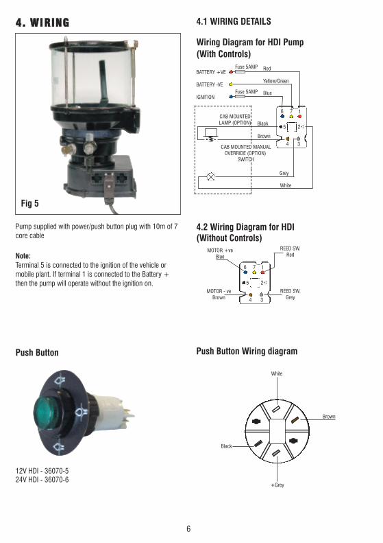
Wiring Diagram for HDI Pump(With Controls)
4.2 Wiring Diagram for HDI(Without Controls)
Push Button Wiring diagram
4
Red
Blue
Fuse 5AMP
Fuse 5AMP
Yellow/Green
White
Grey
Brown
MOTOR - veBrown
MOTOR +veBlue
REED SW.Red
REED SW.Grey
Black
Black
White
+Grey
Brown
CAB MOUNTED MANUALOVERRIDE (OPTION)
SWITCH
4.1 WIRING DETAILS44.. WWIIRRIINNGG
Fig 5
Pump supplied with power/push button plug with 10m of 7core cable
Note:Terminal 5 is connected to the ignition of the vehicle or mobile plant. If terminal 1 is connected to the Battery +then the pump will operate without the ignition on.
Push Button
7 16
25
3
4
7 16
25
3
12V HDI - 36070-524V HDI - 36070-6

7
Alarm Functions
EXTERNALALARMRELAY
(OPTIONAL)
END OF LINESENSOR
(OPTIONAL)
EARTH
2
3
BROWN
BLACK
BLUE
1
Grease Flow Monitor
Wiring for Alarm SW
Remote Alarm Functions
The HDI Pump can be supplied with or without aninternal controller (PCB).
The pump without control facility is fitted with aninternal reed switch; this can be used to monitorthe pumps internal cam rotation.
The pump with control facility has an in-built alarmfunction, which can be connected to an externalalarm relay as an option.In general the HDI is connected to progressivedivider valves as illustrated in Fig (2).The progressive divider valves are designed tofeed a positive set amount of grease to eachconnected point in turn, without missing a pointout. The primary divider valve is fitted with aproximity flow indicator switch, which will signalpositive flow back to the HDI PCB.Should the pump operate and the PCB not receivea flow signal the pump would alarm. This alarmsignal could be connected to an external remoteaudio or visual alarm on the machine or alternativelyconnected to the machines PLC.The PLC could beprogrammed to stop the machine from operatingshould the lubrication system fail to operatecorrectly.
(Fig 2)
Primary divider valve fitted withproximity flow indicator switch
Secondary divider valve
7
Secondary divider valve
Primary divider valve fitted withproximity flow indicator switch
Flow Alarm
4.3. ALARM FUNCTIONS
FLOW
1
2
3
4
EXTERNALALARMRELAY
(OPTIONAL)EARTH
2
3
BROWN
BLACK
BLUE
Wiring for Alarm Switch
4.4. Remote Alarm Functions
The HDI Pump can be supplied with or without an internalcontroller (PCB).
The pump without control facility is fitted with an internalreed switch; this can be used to monitor the pumps internal cam rotation.
The pump with control facility has an in-built alarmfunction, which can be connected to an external alarm
relay as an option.In general the HDI is connected to progressive dividervalves as illustrated.The progressive divider valves are designed to feed apositive set amount of grease to each connected point inturn, without missing a point out. The primary dividervalve is fitted with a proximity flow indicator switch,which will signal positive flow back to the HDI PCB.Should the pump operate and the PCB not receive a flowsignal the pump would alarm. This alarm signal could beconnected to an external remote audio or visual alarm onthe machine or alternatively connected to the machinesPLC.The PLC could be programmed to stop the machinefrom operating should the lubrication system fail to operate correctly.
1. Pump elements (see page 4 & 5)
2. Low level connection (not supplied as standard onbase models)
3. Power cable (30ft) and 7 pin connector supplied as standard with all models (see details on page 8 and wiring diagram on page 6)
4. End of line or primary flow proximity sensor alarm connection (not supplied as standard on base models)
PROXIMITYSWITCH
(OPTIONAL)

3 Ltr Moulded Kit
6 KG Standard Kit
9 KG Standard Kit
15 KG Standard Kit
HDI/SP9/3P
HDI/SP9/6
HDI/SP9/9
HDI/SP9/15
Part No Description
8
4.5. Low Level Sensors
These highly reliable capacitive sensors are fully sealed andencapsulated to operate in the most arduous conditionswith NLGI 2 grease.
Fig 6 shows pictorial view and Fig 7 the version for a 3 litrepump. (Extensions are used for larger capacity reservoirs).
Control Card 12/24V (HDI/SP15)
HDI/SP15
Low level connection
Proxy connection
Power connection
Motor Connection
Low level External Alarm Facility (B+C)
Power/push button plug with 10m cable (A)
Proximity alarm plug (B+C)
HDI/SP9
HDI/SP4
HDI/SP8
Part No Description
4.6 Proximity sensor Conversion kit
B C
Proximity alarm plug A plus pump plug with internal loom to PCB
Low Level Kit
Kit comprises of pump connector, low level and plug
A

9
Time "ON"/Time "OFF" modePress select and enter buttons together for 5 seconds toenter programme mode.
1) Display will show "S1" (Run time) Press enter button then select button to set run time in minutes from "01" to "99" (for example 05 gives a run time of 5 mins ). Will provide run time from 1 min to 99 mins Press enterto accept
2) Display will show "S2" (Delay time) Press enter button, for example to set a delay time of 1 hour 20 mins, pressselect button to display "Ol " then enter to accept, then select button to display "20". Press enter to accept.
3) Display will show "S3" (End of line switch setting)Press enter button, display shows "EL" press select to choose between a) When "EL" is flashing end of line sensing is "OFF" or b) When "EL" is continuously lit endof line sensing is "ON" Press enter to accept. If end of line switch is "ON" next display will show "Ol Select between "Ol " to "10" for the number of cycles of the lubrication system Press enter to accept.
4) Display will show "S4" (low level option) Press enter button, display shows "LL" press select to choose between a) When "LL" is flashing low level sensing is "OFF" or b) When "LL" is continuously lit low level sensing is "ON" Press enter to accept
5) Display shows "PC" (Programming complete) After 10 seconds return to run mode.
S105S20 120s3
S4
PC
EL EL
LL LL
02
ON
ON
OFF
FLASHING
FLASHING
OFF
PROGRAMMED CYCLE
ON TIME
OFF TIMEHOUR
MINS
S 1
PC
CHANGING PROGRAMME
1) Display will show
2) Press select button to choose the setting you want to change S2,S3 etc then press enter
3) After making the change press enter to accept
4) Press select button until display shows ‘PC’ “Programme complete”
Press select and enter buttons together for 5 Secs to enter programming mode
Notes: -To view current programmed settingsa) press the "select" button for 10 seconds this will activatethe programme view mode displaying the setting of eachstep for 3 seconds. After showing "PC" for 3 seconds thepump will return to run mode.
Low level warningb) If a low level alarm is triggered the pump will continueoperating and any alarm warnings will continue until thereservoir is re-filled.
To prime the systemc) set the delay time to "00" hours and "00" minutes. Pleasenote this time setting is not intended as an operating mode.
Note:-The manual override button on the pump can be operated atany time without the need for the ignition circuit to be on, apositive safety benefit. Operating the manual override willstart one cycle of the pre-set run time.
5. HDI PROGRAMME SETTINGProgramming the HDI ControllerProgramming is carried out using the select and enter buttons as shown in the picture.
The setting details are shown on the digital display at eachstage.
Pump Run Time OptionsWith Time “ON” Mode (t) from 1 min to 99 mins.Pump Delay TimeVariable from 1 min to 99 hours 59 mins.
10
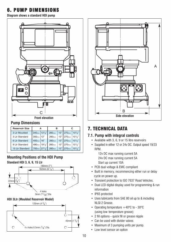
Side elevationFront elevation
Diagram shows a standard HDI pump
A
BC
HDI 3Ltr (Moulded Reservoir Model)
Standard HDI 3, 6, 9, 15 Ltr
Mounting Positions of the HDI Pump
180mm (7”)
120mm (4 3/4”)
45mm (1 3/4”)
162mm (6 1/4”)
22mm (7/8”)
4 holes 9mm (11/32”)Dia
4 x holes 6.5mm (1/4”) Dia.
Pump DimensionsReservoir Size A B C
3 Ltr Moulded 340mm 131/2” 260mm 10” 270mm 101/2”
3 Ltr Standard 300mm 12” 260mm 10” 270mm 101/2”
6 Ltr Standard 400mm 16” 260mm 10” 270mm 101/2”
9 Ltr Standard 490mm 191/2” 260mm 10” 270mm 101/2”
15 Ltr Standard 700mm 271/2” 260mm 10” 270mm 101/2”
66.. PPUUMMPP DDIIMMEENNSSIIOONNSS
7. TECHNICAL DATA7.1. Pump with integral controls
• Available with 3, 6, 9 or 15 litre reservoirs• Supplied in either 12 or 24v DC. Output speed 19/23
RPM.12v DC max running current 5A24v DC max running current 5AStart up current 10A
• PCB dual voltage & EMC compliant• Built in memory, recommencing either run or delay
cycle on power up.• Transient protection to ISO 7637 Road Vehicles.• Dual LED digital display used for programming & run
information• IP65 protected• Uses lubricants from SAE 80 oil up to & including
NLGI 2 Grease.• Operating temperature +40ºC to - 30ºC
(using low temperature grease)• 2 fill options - quick fill or grease nipple• Can be used with divider valves• Maximum of 3 pumping units per pump.• Low level sensor an option

11
HDI FILLING METHODSHDI Dual Fill
C
B
A
All HDI models are supplied with dual fill
(A) standard grease nipple use air operated grease pump to fill the reservoir.
(B) quick release coupling use a hand operated volume bucket pump.
(C) Or alternatively fit the pump with a quickfill adapter and use a quick fill gun to fill the reservoirs.
Hand operated quick fill gun
Quick Fill Gun
Part No. Description
HDI - 57549-1 Quick fill gun
HDI - 36763-1 Straight adapter for the pump
HDI - 36763-2 90 adapter
Bucket Pump
Hand operated bulk fill pump complete with:1.5m hose, female quick release coupling to fit directly onto the Interlube quick connect fitting fitted to thepump. Ideal for use with NLGI 1 or 2 greases.
Part No Description
IL-108501 European Pump (12.5-18 KG), cover 265mm to 310mm
IL-108502 USA Pump (35lb) cover 285mm to 330mm
IL-417001 Grease follower plate 260mm to 298mm
IL-417003 Grease follower plate 300mm to 340mm
HDI-36763-2
HDI-36763-1
8. PUMP FILLING
HDI-57549-1

12
9. TROUBLESHOOTING
PROBLEM POSSIBLE CAUSE REMEDY
A. All lubrication points 1. Empty reservoir 1. Refill the reservoir, using the appear dry. correct lubricant.
2. Inoperative pump 2. Refer to PROBLEM “E”.3. Time between lube cycle is 3. Adjust pump CYCLE TIME
too long. setting.4. Reservoir has been filled with an 4. Remove the lubricant and replace
unsuitable lubricant. with correct grade of lubricant.5. Inoperative Pumping Unit 5. Replace Pumping Unit6. Pumping unit not “sitting” in 6. Remove & refit correctly.
cam ring (USA Version)7. Main Pressure Line 7. Find breakage & replace with
damaged/broken. new hose.8. Reservoir vent blocked from 8. Clear vent and only fill to max
over filling. level.
B. One or more lubrication point 1. Broken or severed secondary 1. Determine cause, and if appears dry while others receive grease lines. necessary, re-route. sufficient lubrication. 2. Incorrect specification of 3. Re-configure divider valve
divider valves. specification to higher output.
C. All lubrication points are 1. Incorrect setting of “on-time” 1. Reduce “On Time” or increase over-lubricated. or “Delay Time”. “Delay Time”, or both.
D. One or more lubrication points 1. Incorrect specification of 1. Re-configure divider valveare over-lubricated. divider valves. specification to lower output.
E. Inoperative pump. 1. No input power. 1. Check for power to the pump.and controller.
2. Fuse is blown. 2. Check in-line fuse. Replace if necessary.
3. Loose wire connection inside 3. Check all wires and connections the pump. in the pump.
4. Defective PCB. 4. Replace PCB.5. Defective Motor. 5. Replace Motor.
F. Inoperative Pumping Unit. 1. Pumping Unit not “sitting” in 1. See Section 7.5cam ring. (USA Version)
2. Inoperative Pump 2. Refer to PROBLEM “E”.3. No Grease flow 3. Replace pumping unit
G. Grease flowing from Pumping 1. One or more lubrication points 1. Remove pipe from fitting and Unit Relief Valve. are blocked, and will not accept flush bearing through with grease
grease. gun. 2. Fault in Divider valve assembly. 2. Replace the faulty Divider valve
13
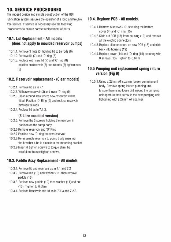
10.4. Replace PCB - All models.
10.4.1.Remove 8 screws (13) securing the bottomcover (4) and ‘O’ ring (15)
10.4.2.Slide out PCB (18) from housing (19) and removeall the electric connectors
10.4.3.Replace all connectors on new PCB (18) and slide back into housing (19)
10.4.4.Replace cover (14) and ‘O’ ring (15) securing with 8 screws (13). Tighten to 0.6Nm
10.5 Pumping unit replacement spring return version (Fig 9)
10.5.1.Using a 27mm AF spanner loosen pumping unit body. Remove spring loaded pumping unit.Ensure there is no loose dirt around the pumping unit aperture then screw in the new pumping unit tightening with a 27mm AF spanner.
10. SERVICE PROCEDURESThe rugged design and simple construction of the HDI
lubrication system assures the operator of a long and trouble
free service. If service is necessary use the following
procedures to ensure correct replacement of parts.
10.1. Lid Replacement - All models (does not apply to moulded reservoir pumps)
10.1.1.Remove 3 nuts (5) holding lid to tie rods (6)10.1.2.Remove lid (7) and ‘O’ ring (8)10.1.3.Replace with new lid (7) and ‘O’ ring (8)
position on reservoir (3) and tie rods (6) tighten nuts(5)
10.2. Reservoir replacement - (Clear models)
10.2.1.Remove lid as in 7.110.2.2. Withdraw reservoir (3) and lower ‘O’ ring (9)10.2.3.Clean around area where new reservoir will be
fitted. Position ‘O’ Ring (9) and replace reservoirbetween tie rods
10.2.4.Replace lid as in 7.1.3.
(3 Litre moulded version)10.2.5.Remove the 3 screws holding the reservoir in
position on the pump body10.2.6.Remove reservoir and ‘O’ Ring10.2.7.Position new ‘O’ ring on new reservoir10.2.8.Re-assemble reservoir to pump body ensuring
the breather tube is closest to the mounting bracket10.2.9.Insert & tighten screws to torque 3Nm, be
careful not to overtighten screws.
10.3. Paddle Assy Replacement - All models
10.3.1.Remove lid and reservoir as in 7.1 and 7.210.3.2.Remove nut (10) and washer (11) then remove
paddle (16)10.3.3.Replace new paddle (12) then washer (11)and nut
(10). Tighten to 6.5Nm10.3.4.Replace Reservoir and lid as in 7.1.3 and 7.2.3

14
11 Pump- Exploded View 3Ltr Moulded

Item
1
2
3
4
5
6
7
8
9
10
11
12
13
14
15
16
17
18
19
20
21
Part No
HDI SP7/3P
HDI SP13/P
HDI SP4HDI SP4/A
HDI SP28
HDI SP8
HDI 2P12/12-24
HDI SP9/3P
HDI SP24
HDI SP25
HDI SP1HDI SP2
HDI SP26
HDI SP14
HDI SP15
HDI SP18HDI SP19
HDI SP27
HDI SP3
PU300/350PU300/350/A
HDI SP11/3P
HDI SP10P
HDI SP5/3P
HDI SP29
Description
3 LT Reservoir
Restrictor Plate
Cam Assy & Seals
Blanking Plug
Proximity Alarm Plug Conversion Kit with Internal Loom
7 Way Connector Assy & PCB Internal Loom 12/24V
Low Level Conversion Kit with Internal Loom+ Low Level sensor
Bottom Cover Assy
Bottom Cover Fixing Screws (BULK)
Spare HDI 12V MotorSpare HDI 24V Motor
Bottom Cover O Ring (BULK)
Motor to PCB Loom
12-24V Standard PCB CNTRL Board
Housing W/O ControlsHousing with Controls
Grease Nipple with Adaptor
Quick Fill Adaptor (MALE)
Pump Element with PRV (UNIT) 350BAR
Paddle Blade Assy
Reservoir Seal 3LTR Moulded
Spare Low Level Sensor 3LTR
Reed Switch
QTY
1
1
1
2
1
1
1
1
1
1
1
1
1
1
1
1
1
1
1
Notes
O Ring (SP10/P) and Screws Incl
Cam for spring return pump elementCam for push-pull pump element
Gaskets, Connector Base, Screws & DinConnector Incl
Gasket, 7 Way Connector, Screws and 7Pin Hirschmann CNCTR Incl.
Gaskets, Connector Base, Screws & DinConnector Incl.
Screws, Seal & Vent Incl.
Gasket Included
Spring Return Pump ElementPush-Pull Pump Element
Nut Included
Lead, Nut & Washers Incl.
Supplied with no Control Version HDI
15
11.1 Parts List

16
12. Pump- Exploded View 3, 6, 9 & 15 Litre Standard
17
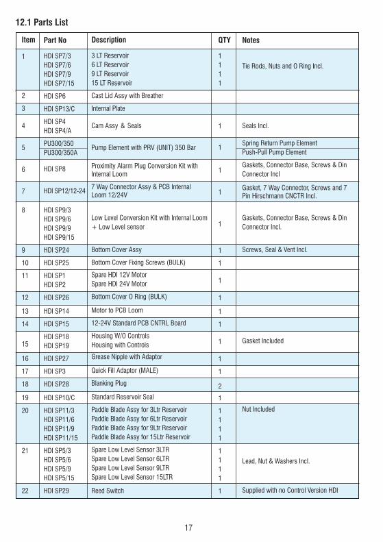
12.1 Parts List
Item
1
2
3
4
5
6
7
8
9
10
11
12
13
14
15
16
17
18
19
20
21
22
Part No
HDI SP7/3HDI SP7/6HDI SP7/9HDI SP7/15
HDI SP6
HDI SP13/C
HDI SP4HDI SP4/A
PU300/350PU300/350A
HDI SP8
HDI SP12/12-24
HDI SP9/3HDI SP9/6HDI SP9/9HDI SP9/15
HDI SP24
HDI SP25
HDI SP1HDI SP2
HDI SP26
HDI SP14
HDI SP15
HDI SP18HDI SP19
HDI SP27
HDI SP3
HDI SP28
HDI SP10/C
HDI SP11/3HDI SP11/6HDI SP11/9HDI SP11/15
HDI SP5/3HDI SP5/6HDI SP5/9HDI SP5/15
HDI SP29
Description
3 LT Reservoir6 LT Reservoir9 LT Reservoir15 LT Reservoir
Cast Lid Assy with Breather
Internal Plate
Cam Assy & Seals
Pump Element with PRV (UNIT) 350 Bar
Proximity Alarm Plug Conversion Kit with Internal Loom
7 Way Connector Assy & PCB InternalLoom 12/24V
Low Level Conversion Kit with Internal Loom+ Low Level sensor
Bottom Cover Assy
Bottom Cover Fixing Screws (BULK)
Spare HDI 12V MotorSpare HDI 24V Motor
Bottom Cover O Ring (BULK)
Motor to PCB Loom
12-24V Standard PCB CNTRL Board
Housing W/O ControlsHousing with Controls
Grease Nipple with Adaptor
Quick Fill Adaptor (MALE)
Blanking Plug
Standard Reservoir Seal
Paddle Blade Assy for 3Ltr ReservoirPaddle Blade Assy for 6Ltr ReservoirPaddle Blade Assy for 9Ltr ReservoirPaddle Blade Assy for 15Ltr Reservoir
Spare Low Level Sensor 3LTRSpare Low Level Sensor 6LTRSpare Low Level Sensor 9LTRSpare Low Level Sensor 15LTR
Reed Switch
QTY
1111
1
1
1
1
1
1
1
1
1
1
1
1
1
1
2
1
1111
1111
1
Notes
Tie Rods, Nuts and O Ring Incl.
Seals Incl.
Spring Return Pump ElementPush-Pull Pump Element
Gaskets, Connector Base, Screws & DinConnector Incl
Gasket, 7 Way Connector, Screws and 7Pin Hirschmann CNCTR Incl.
Gaskets, Connector Base, Screws & DinConnector Incl.
Screws, Seal & Vent Incl.
Gasket Included
Nut Included
Lead, Nut & Washers Incl.
Supplied with no Control Version HDI
18
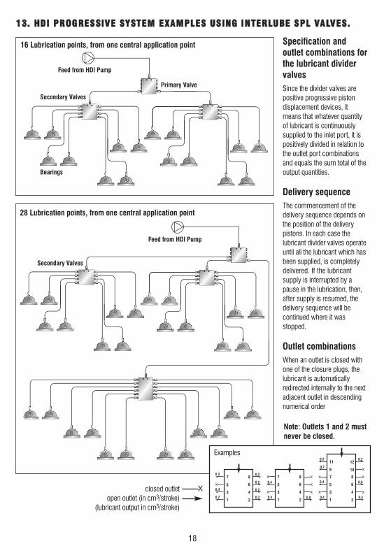
1133.. HHDDII PPRROOGGRREESSSSIIVVEE SSYYSSTTEEMM EEXXAAMMPPLLEESS UUSSIINNGG IINNTTEERRLLUUBBEE SSPPLL VVAALLVVEESS..
16 Lubrication points, from one central application point
28 Lubrication points, from one central application point
Specification and outlet combinations forthe lubricant dividervalvesSince the divider valves arepositive progressive piston displacement devices, itmeans that whatever quantityof lubricant is continuouslysupplied to the inlet port, it ispositively divided in relation tothe outlet port combinationsand equals the sum total of theoutput quantities.
Delivery sequenceThe commencement of the delivery sequence depends onthe position of the delivery pistons. In each case the lubricant divider valves operateuntil all the lubricant which hasbeen supplied, is completelydelivered. If the lubricant supply is interrupted by apause in the lubrication, then,after supply is resumed, thedelivery sequence will be continued where it wasstopped.
Outlet combinationsWhen an outlet is closed withone of the closure plugs, thelubricant is automatically redirected internally to the nextadjacent outlet in descendingnumerical order
X
X
X X
X
X
X
X
X
X
X
70,2 0,2
0,2 0,4
0,4 0,8 0,4 0,4
0,6
0,20,2
0,2
0,4
0,2
0,2
0,4
0,2
8
6
4
2
5
3
1
7 8
6
4
2
5
3
1
7
9
11
8
10
12
6
4
2
5
3
1
Note: Outlets 1 and 2 mustnever be closed.
Examples
closed outletopen outlet (in cm3/stroke)
(lubricant output in cm3/stroke)
X
Feed from HDI Pump
Secondary Valves
Primary Valve
Bearings
Secondary Valves
Feed from HDI Pump

19
Proximity Switch
13.2 DIVIDER VALVE ACCESSORIES
Proximity Adapters
Check Valve Outlet Fittings
Closure Plug
SPL36713-1
SPL 512-4482
SPL- 17499-3
13.1 DIVIDER VALVESStandard Progressive Divider Valves
Standard Divider Valve
Part No Number of Max flowoutlets Monitoring per min
SPL-06 6 200 cc
SPL-06K 6 Indicator Pin 200 cc
SPL-08 8 600 cc
SPL-08K 8 Indicator Pin 600 cc
SPL-10 10 700 cc
SPL-10K 10 Indicator Pin 700 cc
SPL-12 12 800 cc
SPL-12K 12 Indicator Pin 800 cc
SPL-14 14 900 cc
SPL-14K 14 Indicator Pin 900 ccDivider valves with visual indicator pin Divider Valves
• Monobloc design with number of outlets from 6 to 14• Each outlet delivers 0.20ccs/cycle• Crossporting and single outlets possible• Available with cyclic indicator pins• Max operating pressure 350bar• Operating temperature -30ºC to 100ºC• Outlets Tapped M10 x 1• Inlet Tapped 1/8 BSP• Proximity sensor an option
IMPORTANTAll SPL DIVIDER VALVE OUTLETS MUSTBE FITTED WITH SPL CHECK VALVES ORBLANKED OFF WITH SPL CLOSUREPLUGS. NEVER BLANK PORTS 1 & 2 ON ASPL VALVE
SPL-30364-4 M10x1 Check ValveSPL-12374-9 6mm NutSPL-12295-2 6mm Olive
USA Headquarters:Interlube Systems Inc4696 Wadsworth Road, Dayton, Ohio, 45414, USATel: +1 (937) 276 4507 Fax: +1 (937) 276 4518e-mail: [email protected]
AccessoriesA
ccessories
Cata
logue
-Issu
e4
For all Accessories refer to our Cataloguerequest from Interlube Systems Ltd or look onour website: www.interlubesystems.com
Interlube Systems (Malaysia) Sdn.30, Jalan Appollo U5/189, Bandar Pinggiran Subang Sesyen, 40150 Shah Alam, Selangor, Malaysia. Tel: (603) 7845 5377 Fax: (603) 7845 5977Email: [email protected]
ISSUE 02/2011
Interlube Systems LtdSt Modwen Road, Parkway Industrial Estate, Plymouth, Devon, England PL6 8LHTel: +44 (0)1752 676000 Fax: +44 (0)1752 676001e-mail: [email protected] Web Site: www.interlubesystems.com
Plymouth Factory UK


