

SERVICING INFORMATION
TROUBLESHOOTING 7- 1
SPECIAL TOOLS 7- 6
TIGHTENING TORQUE 7-10
SERVICE DATA 7-12
WIRE AND CABLE ROUTING 7-18
WIRING DIAGRAM 7-20
CONTENTS
7

Engine does notstart, or is hard to start.
Engine stalls easily.
Noisy engine.
Slipping clutch
Compression too low1. Excessively worn cylinder or piston rings.2. Stiff piston ring in place.3. Gas leaks from the joint in crankcase, cylinder or cylinder head.4. Damaged reed valve.5. Spark plug too loose.6. Broken, cracked or otherwise failed piston.
Plug not sparking1. Damaged spark plug or spark plug cap.2. Dirty or wet spark plug.3. Defective CDI & Ignition coil unit or stator coil.4. Open or short in high-tension cord.5. Defective ignition switch.
No fuel reaching the carburetor1. Clogged hole in the fuel tank cap.2. Clogged or defective fuel cock.3. Defective carburetor float valve.4. Clogged fuel hose or defective vacuum hose.
1. Carbon deposited on the spark plug.2. Defective CDI & Ignition coil unit.3. Clogged fuel hose.4. Clogged jets in carburetor.5. Clogged exhaust pipe.
Noise appears to come from piston1. Piston or cylinder worn down.2. Combustion chamber fouled with carbon.3. Piston pin, bearing or piston pin bore worn.4. Piston rings or ring grooves worn.
Noise seems to come from crankshaft1. Worn or brunt crankshaft bearings.2. Worn or brunt conrod big-end bearings.
Noise seems to come from final gear box1. Gears worn or rubbing.2. Badly worn splines.3. Worn or damaged bearings of drive shaft for rear axle shaft.
1. Worn or damaged clutch shoes.2. Worn clutch drum.
Complaint Symptom and possible causes Remedy
Replace.Refair or replace.Refair or replace.Replace.Tighten.Replace.
Replace.Clean and dry.Replace.Replace.Replace.
Clean.Clean or replace.Replace.Clean or replace.
Clean.Replace.Clean.Clean.Clean.
Replace.Clean.Replace.Replace.
Replace.Replace.
Replace.Replace.Replace.
Replace.Replace.
Engine idlespoorly.
1. Excessively worn cylinder or piston rings.2. Stiff piston ring in place.3. Gas leaks from crankshaft oil seal.4. Spark plug gaps too wide.5. Defective CDI & Ignition coil unit.6. Defective magneto stator coil.7. Float-chamber fuel level out of adjustment in carburetor.8. Clogged jets in carburetor.9. Broken or damaged reed valve.
Replace.Replace. Replace.Adjust or replace. Replace. Replace. Replace. Clean or adjust. Replace.
7-1 SERVICING INFORMATION
TROUBLESHOOTING
ENGINE
SERVICING INFORMATION 7-2
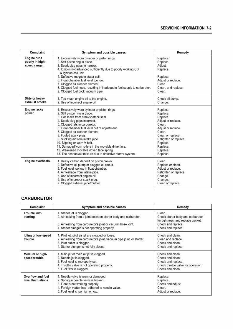
Engine runs poorly in high-speed range.
Dirty or heavy exhaust smoke.
Engine lacks power.
Engine overheats.
1. Excessively worn cylinder or piston rings.2. Stiff piston ring in place.3. Spark plug gaps to narrow.4. Ignition not advanced sufficiently due to poorly working CDI
& Ignition coil unit.5. Defective magneto stator coil.6. Float-chamber fuel level too low.7. Clogged air cleaner element.8. Clogged fuel hose, resulting in inadequate fuel supply to carburetor.9. Clogged fuel cock vacuum pipe.
1. Too much engine oil to the engine.2. Use of incorrect engine oil.
1. Excessively worn cylinder or piston rings.2. Stiff piston ring in place.3. Gas leaks from crankshaft oil seal.4. Spark plug gaps incorrect.5. Clogged jets in carburetor.6. Float-chamber fuel level out of adjustment.7. Clogged air cleaner element.8. Fouled spark plug.9. Sucking air from intake pipe.
10. Slipping or worn V-belt.11. Damaged/worn rollers in the movable drive face.12. Weakened movable driven face spring.13. Too rich fuel/air mixture due to defective starter system.
1. Heavy carbon deposit on piston crown.2. Defective oil pump or clogged oil circuit.3. Fuel level too low in float chamber.4. Air leakage from intake pipe.5. Use of incorrect engine oil.6. Use of improper spark plug.7. Clogged exhaust pipe/muffler.
Replace.Replace.Adjust.Replace.
Replace.Adjust or replace.CleanClean, and replace.Clean.
Check oil pump.Change.
Replace.Replace.Replace.Adjust or replace.Clean.Adjust or replace.Clean.Clean or replace.Retighten or replace.Replace.Replace.Replace.Replace.
Clean.Replace or clean.Adjust or replace.Retighten or replace.Change.Change.Clean or replace.
Trouble with starting.
Idling or low-speed trouble.
Medium or high- speed trouble.
Overflow and fuellevel fluctuations.
1. Starter jet is clogged.2. Air leaking from a joint between starter body and carburetor.
3. Air leaking from carburetor’s joint or vacuum hose joint.4. Starter plunger is not operating properly.
1. Pilot jet, pilot air jet are clogged or loose.2. Air leaking from carburetor’s joint, vacuum pipe joint, or starter.3. Pilot outlet is clogged.4. Starter plunger is not fully closed.
1. Main jet or main air jet is clogged.2. Needle jet is clogged.3. Fuel level is improperly set.4. Throttle valve is not operating properly.5. Fuel filter is clogged.
1. Needle valve is worn or damaged.2. Spring in deedle valve is broken.3. Float is not working properly.4. Foreign matter has adhered to needle valve.5. Fuel level is too high or low.
Clean.Check starter body and carburetor for tightness, and replace gasket.Check and replace.Check and replace.
Check and clean.Clean and replace.Check and clean.Check and replace.
Check and clean.Check and clean.Check and replace.Check throttle valve for operation.Check and clean.
Replace.Replace.Check and adjust.Clean.Adjust or replace.
CARBURETOR
Complaint Symptom and possible causes Remedy
Complaint Symptom and possible causes Remedy

7-3 SERVICING INFORMATION
No sparking or poor sparking.
Spark plug soon becomes fouled with carbon.
Spark plug electrodes overheat or burn.
Magneto does not charge.
Magneto charge, but charging rate is below the specific-ations.
1. Defective CDI & Ignition coil unit.2. Defective spark plug.3. Defective magneto stator coil.4. Loose connection of lead wire.
1. Mixture too rich.2. Idling speed set too high.3. Incorrect gasoline.4. Dirty element in air cleaner.5. Spark plug too cold.6. Incorrect engine oil.
1. Spark plug too hot.2. The engine overheats.3. Spark plug loose.4. Mixture too lean.5. Not enough engine oil.
1. Open or short in lead wires, or loose lead connections.2. Shorted, grounded or open magneto coil.3. Shorted or open regulator/rectifier.
1. Lead wires tend to get shorted or open-circuited or loosely connected at terminal.
2. Grounded or open-circuited stator coils of magneto.3. Defective regulator/rectifier.4. Defective cell plates in the batttery.
Replace.Replace.Replace.Connect/tighten.
Adjust carburetor.Adjust carburetor.Change.Clean.Replace by hot type plug.Replace.
Replace by hot type plug.Turn up.Retighten.Adjust carburetor.Check oil pump.
Repair, replace or retighten.Replace.Replace.
Repair, or retighten.
Replace.Replace.Replace the battery.
ELECTRICAL
Magneto overcharges
Ustable charging.
Starter button is not effective.
1. Internal short-circuit in the battery.2. Resistor element in the regulator/rectifier damaged or defective.3. Regulator.rectifier unit poorly grounded.
1. Lead wire insulation frayed due to vibration, resulting in intermittent shorting.
2. Magneto coil internally shorted.3. Defective regulator/rectifier.
1. Battery run down.2. Defective switch contacts.3. Brushes not seating properly on commutator in starter motor.4. Defective starter relay.5. Defective starter pinion gears.6. Defective front or rear brake light switch circuit.
Replace the battery.Replace.Clean and tighten groun connection.
Repair or replace.
Replace.Replace.
Recharge or replace.Replace.Repair or replace.Replace.Replace.Replace or repair.
Battery runs downquickly.
Reversed batterypolarity.
Battery dischargestoo rapidly.
1. The charging method is not correct.
2. Cell plates have lost much of their active material as a result of over-charging.
3. A short-circuit condition exists within the battery due to excessive accumulation of sediments caused by the incorrect electrolyte.
4. Battery is too old.
1. The battery has been connected the wrong way round in thesystem, so that it is being charged in the reverse direction.
1. Dirty container top and sides.2. Battery is too old.
Check the magneto and regulator/rec-tifier circuit connections, and make necessary adjustments to obtain spe-cified charging operation.Replace the battery, and correct the charging system.Replace the battery.
Replace the battery.
Replace the battery and be sure toconnect the battery properly.
Clean.Replace.
BATTERY
Complaint Symptom and possible causes Remedy
Complaint Symptom and possible causes Remedy

SERVICING INFORMATION 7-4
Handling feels too heavy.
Wobbly handle.
Wobbly front wheel.
Front suspension too soft.
Front suspension too stiff.
Noisy front suspension.
Wobbly rear wheel.
Rear suspension too soft.
Noisy rear suspension.
1. Steering stem nut overtightened.2. Broken bearing/race in steering stem.3. Distorted steering stem.4. Not enough pressure in tires.
1. Loss of balance between right and left front suspension.2. Distorted front axle or crooked tire.
1. Distorted wheel rim.2. Worn front wheel bearings.3. Defective or incorrect tire.4. Loose nut on axle.5. Loose nuts on the rear shock.6. Worn engine mounting bushing.7. Loose nuts or bolts for engine mounting.
1. Weakened springs.2. Oil leakage of shock absorber.
1. Not enough grease.2. Worn suspension arm spacer.
1. Not enough grease.2. Loose nuts on suspension.
1. Distorted wheel rim.2. Defective or incorrect tire.3. Loose nuts on the rear shock absorber.4. Worn engine mounting bushing.5. Loose nuts or bolts for engine mounting.
1. Weakened spring.2. Oil leakage of rear shock absorber.
1. Loosen nuts on shock absorber.2. Worn engine mounting bushing.
Adjust.Replace.Replace.Adjust.
Replace.Replace.
Replace.Replace.Replace.Retighten.Retighten.Replace.Tighten.
Replace.Replace.
Refill.Replace.
Refill.Retighten.
Replace.Replace.Replace.Replace.Retighten.
Replace.Replace.
Retighten.Replace.
CHASSIS
Insufficient brakepower.
Brake squeaking.
1. Leakage of brake fluid from hydraulic system.2. Worn pad.3. Oil adhesion on engaging surface of pad.4. Worn disc.5. Air entered into hydraulic system.6. Worn shoe.7. Friction surfaces of shoes are dirty with oil.8. Excessively worn drum.9. Too much brake lever play.
1. Carbon adhesion on pad surface.2. Tilted pad.3. Damaged wheel bearing.4. Worn pad.5. Foreign substance entered into brake fluid.6. Clogged return ports of master cylinder.7. Brake shoe surface glazed.8. Loose front-wheel axle or rear-wheel axle nut.9. Worn shoe.
Repair or replace.Replace.Clean disc and pads.Replace.Bleed air.Replace.Replace.Replace.Adjust.
Repair surface with sandpaper.Modify and fitting.Replace.Replace.Replace brake fluid.Disassemble and clean master cylinder.Repair surface with sandpaper.Tighten to specified torque.Replace.
BRAKES
Complaint Symptom and possible causes Remedy
Complaint Symptom and possible causes Remedy

7-5 SERVICING INFORMATION
Excessive brake lever stroke.
Leakage of brake fluid.
Brake drags.
1. Air entered into hydraulic system.2. Insufficient brake fluid.
3. Improper quality of brake fluid.4. Worn brake cam lever.5. Excessively worn shoes and/or drum.
1. Insufficient tightening of connection joints.2. Cracked hose.3. Worn piston seal.
1. Rusty moving parts.
Bleed air.Replenish fluid to normal lever;bleed air.Replace with correct fluid.Replace.Replace.
Tighten to specified torque.Replace.Replace.
Clean and lubricate.
Complaint Symptom and possible causes Remedy

SERVICING INFORMATION 7-6
SPECIAL TOOLS
Special tools Part Number∙Part Name∙Description
09900-00401
“L”type hexagon wrench set
Tighten hexagon bolt
09900-00410
Hexagon wrench set
Tighten hexagon bolt
09900-05108
Snap ring pliers
Circlip remove and remounting
09900-06105
Snap ring pliers
Circlip remove and remounting
09900-06107
Snap ring pliers
Circlip remove and remounting
09900-09003
Impact driver set
Remove and remounting of fixed screw
09900-20102
Vernier calipers
Measure thickness
09900-20202Micrometer(1/100mm, 25-50mm)
Measure height of cam
09900-20203Micrometer(1/100mm, 50-75mm)
Measure outside diameter of piston
Special tools Part Number∙Part Name∙Description
09900-20205Micrometer(1/100mm, 0-25mm)
Measure outside diameter of piston pin
09900-20508Cylinder gauge set(1/100mm, 40-80mm)
Measure inside diameter of cylinder
09900-20602Dial gauge(1/100mm, 1mm)
Measure inside diameter of cylinder
09900-20605Dial calipers(1/100mm, 10-34mm)
Measure width of conrod big-end
09900-20606Dial gauge(1/100mm, 10mm)
Measure run-out of wheel
09900-20701
Magnetic stand
Used with Dial gauge
09900-20806
Thickness gauge
Measure clearance of piston ring
09900-21304
V-block set
Used with Magnetic stand
09900-21602
CCI Oil gauge
A gauge to inspect performance of oil pump

7-7 SERVICING INFORMATION
Special tools Part Number∙Part Name∙Description
09900-22401Small bore gauge(10-18mm)
Measure inside diameter of conrod small-end
09900-25002
Pocket tester
Measure voltage, electric current, resistance
09900-26006
Tachometer
Measure rotational frequency of engine
09900-28107
Electro tester
Inspect ignition coil
09910-20115
Conrod holder
Used to lock the crankshaft
09910-32812
Crankshaft installer
Used to install the crankshaft in the crankcase
09913-14541
Fuel level gauge set
Measure height of carburetor
09913-50121
Oil seal remover
Used to remove the oil seal
Special tools Part Number∙Part Name∙Description
09913-60710
Bearing remover
Remove bearing with the rotor remove sliding shaft
09913-75520
Bearing installer
Used to drive bearing in
09913-75821
Bearing installer
Used to drive bearing in
09913-75830
Bearing installer
Install rear axle shaft oil seal
09913-76010
Bearing installer
Install crankshaft bearing
09915-63310
Compression gauge adapter
Used with compression gauge
09915-64510
Compression gauge
Measure cylinder compression
09900-22301
Plastic gauge
Measure clearance of crankshaft thrust
09916-84511
Tweezers
Remove and remounting valve cotter pin.
09920-13120
Crankcase separater
Seprate to crankcase

SERVICING INFORMATION 7-8
Special tools Part Number∙Part Name∙Description
09923-74510
Bearing remover (20~35mm)
Remove bearing with the rotor remove sliding shaft
Special tools Part Number∙Part Name∙Description
09940-10122
Clamp wrench
A hook wrench to adjust the steering head of motorcycle
09924-84521
Bearing installer
Used to drive small bearing in
09925-98221
Bearing installer
Used to drive bearing in
09930-10121
Spark plug socket wrench set
Remove and remounting spark plug
09930-30102
Rotor remove sliding shfat
Used to with bearing remover or rotor remover
09930-30163
Rotor remover
Attached to the top of sliding shaft when removing rotor
09930-32420
Rotor holder
Remove and remounting rotor
09930-40113
Rotor holder
Widely used to lock rotary parts such as a flywheel magneto
09940-34520
T-handle
Remove and remounting front fork oil cylinder
09921-20210
Bearing remover (12mm)
Remove oil seal or bearing
09922-55131
Bearing installer
Used to drive bearing in
09923-73210
Bearing remover (17mm)
Remove bearing with the rotor remove sliding shaft
09921-20200
Bearing remover (10mm)
Remove oil seal or bearing
09940-50113
Front fork oil seal installer
Install front fork oil seal
09941-34513
Bearing installer
Install steering outer race
09941-50110
Wheel bearing remover
Remove wheel bearing
09940-34561
Front fork assembling tool attachment “D”
Used with T-handle

7-9 SERVICING INFORMATION
Special tools Part Number∙Part Name∙Description
09943-74111
Front fork oil level gauge
Used to drain the fork oil to the specified level
09943-88211
Bearing remover
Remove rear axle shaft bearing
09951-76010
Bearing installer
Used to drive bearnig in

SERVICING INFORMATION 7-10
ITEM
Magneto rotor nut
Muffler mounting bolt
Exhaust pipe nut
Spark plug
Cylinder head nut
Engine mounting bolt
Engine mounting bracket bolt
Oil drain plug
Oil level bolt
Oil pump bolt
Clutch shoe nut
Clutch housing nut
Kick starter driven nut
Kick starter lever bolt
35 ~ 45
18 ~ 28
8 ~ 12
25 ~ 30
8 ~ 12
40 ~ 60
48 ~ 72
9 ~ 15
9 ~ 15
3 ~ 5
40 ~ 60
40 ~ 60
40 ~ 60
8 ~ 12
3.5 ~ 4.5
1.8 ~ 2.8
0.8 ~ 1.2
2.5 ~ 3.0
0.8 ~ 1.2
4.0 ~ 6.0
4.8 ~ 7.2
0.9 ~ 1.5
0.9 ~ 1.5
0.3 ~ 0.5
4.0 ~ 6.0
4.0 ~ 6.0
4.0 ~ 6.0
0.8 ~ 1.2
kg∙mN∙m
TIGHTENING TORQUE
ENGINE

7-11 SERVICING INFORMATION
TIGHTENING TORQUE CHARTFor other bolts and nuts who’s torque is not listed, refer to this chart :
Conventional or “4”marked boltBolt Diameter(mm)
“7”marked bolt
4
5
6
8
10
12
14
16
18
1.0 ~ 2.0
2.0 ~ 4.0
4.0 ~ 7.0
10.0 ~ 16.0
22.0 ~ 35.0
35.0 ~ 55.0
50.0 ~ 80.0
80.0 ~ 130.0
130.0 ~ 190.0
0.1 ~ 0.2
0.2 ~ 0.4
0.4 ~ 0.7
1.0 ~ 1.6
2.2 ~ 3.5
3.5 ~ 5.5
5.0 ~ 8.0
8.0 ~ 13.0
13.0 ~ 19.0
1.5 ~ 3.0
3.0 ~ 6.0
8.0 ~ 12.0
18.0 ~ 28.0
40.0 ~ 60.0
70.0 ~ 100.0
110.0 ~ 160.0
170.0 ~ 250.0
200.0 ~ 280.0
0.15 ~ 0.3
0.3 ~ 0.6
0.8 ~ 1.2
1.8 ~ 2.8
4.0 ~ 6.0
7.0 ~ 10.0
11.0 ~ 16.0
17.0 ~ 25.0
20.0 ~ 28.0
kg∙mN∙m kg∙mN∙m
ITEM
Rear brake cam lever bolt
Rear shock absorber bolt
Rear axle nut
Steering stem lock nut
Front brake disc bolt
Front brake master cylinder bolt
Front brake air bleeder valve
Front brake caliper mounting bolt
Front brake hose union bolt
Front axle nut
Front fork bolt
Handlebar set bolt
Handlebar clamp nut
6 ~ 9
22 ~ 35
60 ~ 90
60 ~ 100
18 ~ 28
8 ~ 12
6 ~ 9
18 ~ 28
20 ~ 25
33 ~ 52
35 ~ 55
22 ~ 28
48 ~ 52
0.6 ~ 0.9
2.2 ~ 3.5
6.0 ~ 9.0
6.0 ~ 10.0
1.8 ~ 2.8
0.8 ~ 1.2
0.6 ~ 0.9
1.8 ~ 2.8
2.0 ~ 2.5
3.3 ~ 5.2
3.5 ~ 5.5
2.2 ~ 2.8
4.8 ~ 5.2
kg∙mN∙m
CHASSIS

SERVICING INFORMATION 7-12
SERVICE DATA
ITEM
Piston to cylinder clearance
Cylinder bore
Piston diam.
0.065 ~ 0.075
41.005 ~ 41.020
10.002 ~ 10.010
9.995 ~ 10.000
0.120
41.07
40.885
0.1
0.1
3.2
3.1
0.75
0.75
10.030
9.980
40.935 ~ 40.950Measure at 15mm from the skirt end
Approx. 4.5
Approx. 4.3
0.10 ~ 0.25
0.10 ~ 0.25
0.02 ~ 0.06
0.02 ~ 0.06
Cylinder distortion
Cylinder head distortion
Piston ring clearance(Free condition)
Piston ring clearance(Assembling condition)
Piston ring - ring groove clearance
Piston pin bore I.D
Piston pin O.D
STANDARD LIMIT
1st
2nd
1st
2nd
1st
2nd
CYLINDER + PISTON + PISTON RING Unit : mm
Unit : mmCONROD + CRANKSHAFT
ITEM
Conrod small end I.D.
Conrod big end runout
Crank web to wed width
Crankshaft runout
14.003 ~ 14.011
35 ± 0.1
14.047
3.0
0.08
STANDARD LIMIT

7-13 SERVICING INFORMATION
Unit : mmCLUTCH
ITEM
Clutch housing I.D.
Clutch shoe thickness
Clutch in rpm
Clutch tight rpm
110.00 ~ 110.15
3.0
3,600 ± 200 rpm
6,000 ± 200rpm
110.35
2.0
STANDARD LIMIT
Unit : mmOIL PUMP
ITEM
Oil pump reduction ratio 30.000(30/1)
STANDARD
Unit : mmTRANSMISSION
ITEM
Final reduction ratio
Gear ratios
V-belt width
V-belt thickness
Movable drive face spring free length
12.0
2.997 ~ 0.813
16.5 ± 0.6
8.0 ± 0.6
143.8
15.3
135 ~ 153
STANDARD LIMIT

SERVICING INFORMATION 7-14
CARBURETOR
ITEM SPECIFICATION
Carburetor type
Main bore size
I.D. No.
Idle rpm
Fuel level
Main jet (M.J.)
Main air jet (M.A.J.)
Jet needle (J.N.)
Needle jet (N.J.)
Pilot jet (P.J.)
Throttle valve (T.V.)
By-pass (B.P.)
Valve seat (V.S.)
Stater jet (G.S.)
Pilot screw (P.S.)
Pilot outlet (P.O.)
Throttle cable play
Unit : mm
VM14
ф 14
HG 266
1,800 ± 50 rpm
24.5
55
1.0
3E17-3
E-2
25
3.0
2.4 ± 0.05
1.2
25
0.8
0.5 ~ 1.0

7-15 SERVICING INFORMATION
WATTAGE
ITEM
Head lamp bulb
Tail/Brake lamp bulb
Turn signal lamp bulb
Turn signal / Oil level check light pilot lamp
Speedometer lamp bulb
Unit : W
SPECIFICATION
Unit : mmELECTRICAL
ITEM SPECIFICATION NOTE
Ignition timing
Spark plug
20�at 1,000 rpm
Over 8 mm
BR8HSA
0.6 ~ 0.7
Type
Gap
Spark performance
Regulated voltage
No-load performance of A.C. generator
Starter relay resistance
Ignition coil resistance
Stator coil resistance
Type designation
Capacity
Standard electrolyte S.G.
Battery
Fuse
0.19 ~ 0.24 Ϊ
5.4 ~ 6.6 ㏀
0.54 ~ 0.80 Ϊ
0.69 ~ 1.03 Ϊ
220 ~ 260 Ϊ
90 ~ 110 Ϊ
Y/W-Ground
W/R-Ground
B/R-Ground
Br-W
13.0 ~ 16.0 V at 5,000 rpm
More than 17V (at 5,000 rpm)
0 ~ 70 Ϊ
YT4L-BS
12V, 3AH
1.32 at 20℃ (68℉)
15W × 2
5 / 10W
10W × 4
1.7W / 17W
1.7W × 2
10 A
Primary
Secondary
Lighting coil
Charging coil
Exciting coil
Pick-up coil
Do not use except the specified bulb (Wattage).
CAUTION

SERVICING INFORMATION 7-16
Unit : mmBRAKE+WHEEL
ITEM
Brake drum I.D
Brake lining thickness
Brake disc plate thickness
Brake disc plate runout
Master cylinder bore I.D.
Master cylinder piston diam.
Brake caliper I.D.
Brake caliper piston diam.
Brake lever play
Wheel rim runout
Axle shaft runout
Tire size
Tire tread depth
STANDARD LIMIT
Front
Rear
Rear
Rear
Front
Front
Front
Front
Front
Front
Axial
Radial
Front
Front
Rear
Front
Rear
5 ~ 20
15 ~ 25
100
99.2
4.0 ± 0.2
11.000 ~ 11.043
10.957 ~ 10.984
30.230 ~ 30.306
30.150 ~ 30.200
110/70-12 47J
120/70-12 51J
100.7
96
3.5
0.30
11.055
10.945
30.315
30.140
3.0
3.0
0.25
1.6
1.6

7-17 SERVICING INFORMATION
TIRE PRESSURE
SUSPENSION
COLD INFLATIONTIRE PRESSURE
FRONT
REAR
SOLO RIDING
kPa kg/㎠
123
196
1.25
2.00
172
221
1.75
2.25
kPa kg/㎠
DUAL RIDING
ITEM STANDARD LIMIT
Front fork stroke
Front fork spring length(Free condition)
Front fork oil specification
Front fork oil capacity(One side)
Rear wheel travel
75
290.9
TELLUS # 37
50 cc
66
Unit: mm
ITEM
Fuel type
FUEL + OIL
Gasoline used should be graded 85 ~ 95 octane or higher. An unleaded gasoline is recommended.
1.0 ~ 1.2 ㎖(at 3,000 rpm for 5 minutes)
I.D 60㎖/HrF.O 100㎖/Hr
APOLLOIL BIKE-K, HYPOL HS
SAE 10W/30 or 10W/40 multi-grade motor oil
4.8 ℓ
1.0 ℓ
Replace
Overhaul
110 ㎖
130 ㎖
DOT 4
Fuel tank capacity
Engine oil type
Engine oil capacity
Brake fluid type
Transmission oil type
Transmission oil capacity
Engine oil discharge amount
SPECIFICATION NOTE

SERVICING INFORMATION 7-18
Rear turnsignal L
Rear turnsignal R/L
Rear turnsignal R 09407-22402Lamp assy, Tail & StopRear turnsignal R/L
Fuse case
09407-22402
Clamp
Ignition coil
Brake cable
Rear brakecable
Engine earth
09407-22402Starter motormagneto
Starter relay
Switch thermo
Battery cover
REAR BRAKE
WIRE AND CABLE ROUTING

7-19 SERVICING INFORMATION
Turn
sign
al re
lay
Har
ness
Ste
erin
g lo
ck
Fend
er, F
ront
upp
er
Spe
edom
eter
cab
leH
arne
ss
Rea
r bra
ke c
able
Thro
ttle
cabl
eM
aste
r cyl
inde
r hos
e
CD
I uni
t
Hor
n
Reg
ulat
orFr
ont t
urns
igna
l RH
/LH
Hea
d la
mp
Cla
mp
Har
ness
Thro
ttle
cabl
eB
rake
cab
le
Har
ness
Spe
edom
eter
cabl
e
Hea
d la
mp
Fron
t tur
nsig
nal R
H/L
HR
egul
ator
Thro
ttle
cabl
e
Bra
keho
se
Rea
r bra
keca
ble
Sta
rter m
otor
mag
neto
Eng
ine
earth
Sta
rter m
otor
Fram
e ea
rth
Fram
e
Har
ness
Thro
ttle
cabl
e
Rea
r fen
der
Shie
ld le
g lo
wer
rear
Har
ness
Rea
r tur
nsig
nal R
H/L
H
Rea
r bra
keca
ble
Sta
rter m
otor
Hea
ter c
arbu
reto
rS
hiel
d le
g lo
wer
rear
Hel
met
box
Igni
tion
coil
Cla
mp
Sw
itch
ther
mo
0940
7-22
402
Oil
tank
0940
7-22
402
Lam
p as
sy T
ail &
Sto
p
Fuse
cas
eB
atte
ry, �
, � Oil
leve
l gau
ge
Rea
r tur
nsig
nal R
/LLa
mp
assy
Tai
l & S
top
coup
le
P.T.C
Fuel
tank
C
Fro
nt
Fro
nt
BD
VIE
W D
VIE
W C
CA
BL
E
RE
AR
TU
RN
SIG
NA
L L
AM
P VIE
W B

SERVICING INFORMATION 7-20
WIR
E C
OLO
R
B
: Bla
ckLg
: Lig
ht g
reen
Y: Y
ello
wR
B: R
ed w
ith B
lack
trac
erB
r: B
row
nO
: Ora
nge
BG
: Bla
ck w
ith G
reen
trac
erR
W: R
ed w
ith W
hite
trac
erG
: Gre
enR
: Red
BW
: Bla
ck w
ith W
hite
trac
erW
B: W
hite
with
Bla
ck tr
acer
Gr
: Gra
yS
b: L
ight
blu
eB
R: B
lack
with
Red
trac
erW
R: W
hite
with
Red
trac
erL
: Blu
eW
: Whi
teLW
: Blu
e w
ith W
hite
trac
erY
B: Y
ello
w w
ith B
lack
trac
er
Car
bure
tor,
Hea
ter
Reg
ulat
orO
il ga
uge
Fuel
gau
geH
orn
Fron
t bra
ke s
witc
h
Fron
t tur
nsig
nal R
H
Hea
d la
mp
Fron
t tur
nsig
nal L
H
Hor
n
Turn
sign
al
Igni
tion
switc
hS
park
plu
g
Sta
rter m
otor
Bat
tery
Eng
ine
earthR
ear t
urns
igna
l LH
Rea
r tur
nsig
nal R
H
Tail
& S
top
Rea
r bra
ke
switc
hH
andl
e sw
itch
LH
Han
dle
switc
h R
HS
peed
omet
er
Re
ar
turn
sig
na
lF
ront tu
rnsi
gnal
Oil
pilo
t la
mp
turn
signal p
ilot la
mp
Illu
min
atio
n
10 10 1.7
1.7
1.7×
25 10
15×
2
Rea
r co
mbi
natio
n
He
ad
lma
pL
am
p
Tail
Sto
p
DE
ST
WIRING DIAGRAMTh
erm
o sw
itch
P.T
.CFr
ame
earth
Turn
sign
al re
lay
Sta
rter
Ligh
ting
Mag
neto
C.D
.I un
it
Ignitio
n coil
Sta
rter r
elay

Prepared by
HYOSUNG MOTORS & MACHINERY INC.
2nd Ed. NOV. 1999
Manual No. 99000-91310Printed in Korea


