

Shock Absorberand Rate Control Product Catalog
Solutions in Energy Absorption and Vibration Isolation.
Shock
Abso
rber
and
Rate
Contro
lP
roduct
Catalo
g
Shock Absorbers and Rate Controls
Cover2003 3/31/03 2:13 PM Page 2

Enidine: Solutions in Energy Absorption and Vibration Isolation.Enidine: Solutions in Energy Absorption and Vibration Isolation.
Cover2003 3/31/03 2:14 PM Page 3
iInternet: www.enidine.com Toll Free:1-800-852-8508 Fax: 1-716-662-1909
Greater productivity and less downtime. For more than 30 years, customers have relied on Enidine products to help make their machinery and equipment perform quietly, safely and more efficiently at higher speeds. For original equipment manufacturers and aftermarket applications, Enidine offers a unique combination of productselection, engineering excellence and technical support to meeteven the toughest energy absorption application requirements.
Responsive global operations. Enidine is a worldwide organization, with manufacturing facilities and headquarters inOrchard Park, New York, USA; Bad Bellingen, Germany; andYokohama, Japan. Additional sales offices are located inCalifornia, Mexico and the United Kingdom.
Highly trained distributors. Each geographic region is supported by a well-established distributor network that sharesour company’s commitment to customer service and quality. All Enidine distributors receive extensive training in identifying the best product for your application.
Teamwork. Working as a team, our global engineering, manufacturing, sales and distribution network allow for timelyresponse to your needs with uncompromised excellence.
Communication. Our mission at Enidine has always been to be an industry leader in energy absorption and vibration isolation solutions. In carrying out that mission, we've made it paramount to communicate directly with our customers, distributors, representatives, and employees to better understand and respond to your needs. This ongoing interaction has helped make Enidine the growing, vibrant, global presence it is today.
Custom solutions capabilities. If you are unsure whether one of our standard products meets your requirements, feel free to speak with one of our technical representatives toll-free at 1-800-852-8508, or contact us via e-mail at [email protected].
Enidine engineers continue to monitor and influence trends in the motion control industry, allowing us to remain at the forefront of new energy absorption product development. Our experienced engineering team has designed custom solutions for a wide variety of challenging applications, including automated warehousing systems and shock absorbers for hostile industrial environments such as glass manufacturing, among others. These custom application solutions have proven to be critical to our customers’ success.Let Enidine engineers do the same for you.
For better performance and productivity, call your local Enidine representative.
Enidine is widely recognized as the preferred source forenergy absorption and vibration isolation products.
Enidine is widely recognized as the preferred source forenergy absorption and vibration isolation products.
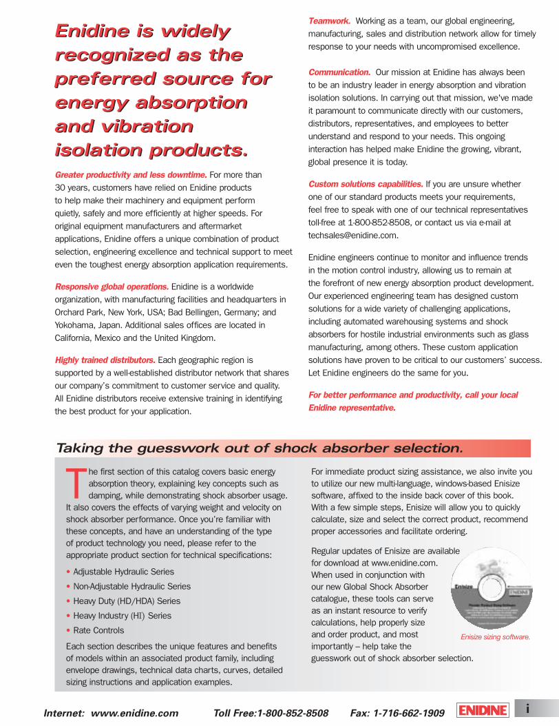
The first section of this catalog covers basic energyabsorption theory, explaining key concepts such as damping, while demonstrating shock absorber usage.
It also covers the effects of varying weight and velocity onshock absorber performance. Once you’re familiar withthese concepts, and have an understanding of the type of product technology you need, please refer to the appropriate product section for technical specifications:
Each section describes the unique features and benefits of models within an associated product family, includingenvelope drawings, technical data charts, curves, detailedsizing instructions and application examples.
For immediate product sizing assistance, we also invite youto utilize our new multi-language, windows-based Enisize software, affixed to the inside back cover of this book. With a few simple steps, Enisize will allow you to quickly calculate, size and select the correct product, recommendproper accessories and facilitate ordering.
Regular updates of Enisize are availablefor download at www.enidine.com.When used in conjunction with our new Global Shock Absorber catalogue, these tools can serve as an instant resource to verify calculations, help properly size and order product, and most importantly – help take the guesswork out of shock absorber selection.
Taking the guesswork out of shock absorber selection.
Enisize sizing software.
• Adjustable Hydraulic Series
• Non-Adjustable Hydraulic Series
• Heavy Duty (HD/HDA) Series
• Heavy Industry (HI) Series
• Rate Controls
ShockCover5-2B 3/31/03 2:28 PM Page i

Internet: www.enidine.com Toll Free: 1-800-852-8508 Fax: 1-716-662-1909ii
Table of Contents
Adjustable Hydraulic Series shock absorbers offer the flexibility to vary the resisting force with the simple turn of an adjustment knob, should input parameters change (weight, impact velocity, drive force, etc.) or are not clearly defined. Adjustable units provide the highest damping efficiency while minimizing structural requirements (see Product Locator, page 16).
Non-Adjustable Hydraulic Series shock absorbers accommodate a wide range of energy conditions without adjustment. Higher energy capabilities are provided in a small overall envelope size. These fixed-orifice designs provide consistent performance with tamperproof reliability (see Product Locator, page 32), and are available with a variety of accessories (see pages 41-46).
OEM SeriesThe OEM Hydraulic Series is the industry standard for general shock absorber applications. A wide range of energy capacities, sizes, mounting styles and other options are available.
TK SeriesVersatile, miniature hydraulic shock absorbers ideally suited for effective, reliable deceleration of light loads.
PRO SeriesUnique progressive damping hydraulic shock absorbers offer softer stops for medium-to-high impact velocity applications and conveniently accommodate varying energy conditions without adjustment.
PM SeriesSelf-compensating, hydraulic shock absorbers that conveniently accommodatean extensive range of varying energy shock absorption applications, including low impact velocity and high drive force conditions, without requiring adjustment.
34
19-25
39-40
35-38
STH SeriesCustom-orificed, compact hydraulic shock absorbers that absorb maximum energy for their size and weight.
34
Table of ContentsN
ON
-AD
JUSTA
BLE
SAD
JUSTA
BLE
S
Enidine: Solutions in Energy Absorption and Vibration Isolation Inside Front Cover
Product Technologies, Engineering Capabilities, Global Service and Support 1-2
Overview of Energy Absorption Theory 3-4
Sizing Examples 5-12
Installation Instructions 13-14
Adjustable Hydraulic Series Shock Absorbers 15-30
Non-Adjustable Hydraulic Series Shock Absorbers 31-46
ShockCover5-2B 3/31/03 2:28 PM Page ii

iiiInternet: www.enidine.com Toll Free:1-800-852-8508 Fax: 1-716-662-1909
HD/HDA Series shock absorbers should be selected when the application involves heavy loads with high energy absorption requirements. Typical applications include safety stops for overhead/stacker cranes, people movers and large material handling systems. These units, available in both adjustable and non-adjustable models, are capable of meeting OSHA, AISE, CMAA, DIN and ISO standards (see Product Locator, page 47).
Hydraulic Rate Controls are used to control the velocity of a moving load through its entire linear or rotational motion. Adjustable and non-adjustable models are available in both double acting (compression/tension) and single acting (compression or tension) configurations. All units have hardened/plated piston rods, long-life seals and an extra-long bearing to assure reliability and durability (see Product Locator, page 68).
ADA SeriesAdjustable double acting hydraulic series of dampers controls both linear and rotational (hinged) loads with unique interchangeable cartridges. Adjustable, fixed or free flow cartridges permit motion control flexibility in tension and/or compression modes.
DA SeriesDouble acting, custom orificed, hydraulic dampers are ideal for high energy applications requiring damping/rate control in tension, compression, or both.
HD/HDA SeriesLarge bore, heavy-duty adjustable and non-adjustable hydraulic models smoothly and safely decelerate large moving loads. Integral accumulator replaces mechanical return spring, thus minimizing unit’s length, weight and cost.
Enidine’s Heavy Industry (HI) Series buffers safely protect heavy machinery and equipment during the transfer of materials and movement of products. The large-bore, high-capacity buffers are individually designed to decelerate moving loads under various conditions and in compliance with industry mandated safety standards. Control of bridge cranes, trolley platforms, large container transfer and transportation safety stops are typical installations.Industry-proven design technologies, coupled with the experience of a globally installed product base, ensure deliverable performance that exceeds customer expectations.
HI SeriesHI Series buffer models can decelerate loads with varying velocities from 6 in./sec. up to 200 in./sec. (0.15 m/sec. to 5.0 m/sec.).All models are custom-orificed for specific application requirements.
71-75
76
HI
SER
IES
RATE C
ON
TR
OLS
Application Examples 77-80
Sizing Worksheet 81
Enisize Sizing Software Inside Back Cover
Heavy Duty (HD/HDA) Series Shock Absorbers 47-62
Heavy Industry (H ) Series Buffers 63-66
Rate Controls 67-76
HD
SERIE
S
ShockCover5-2B 3/31/03 2:28 PM Page iii
Internet: www.enidine.com Toll Free: 1-800-852-8508 Fax: 1-716-662-19091
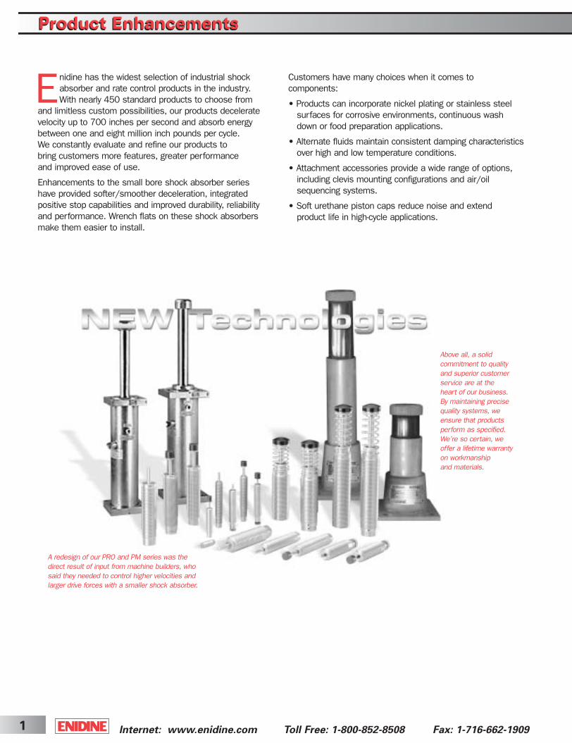
Enidine has the widest selection of industrial shockabsorber and rate control products in the industry. With nearly 450 standard products to choose from
and limitless custom possibilities, our products deceleratevelocity up to 700 inches per second and absorb energybetween one and eight million inch pounds per cycle. We constantly evaluate and refine our products tobring customers more features, greater performance and improved ease of use.
Enhancements to the small bore shock absorber series have provided softer/smoother deceleration, integrated positive stop capabilities and improved durability, reliabilityand performance. Wrench flats on these shock absorbersmake them easier to install.
Customers have many choices when it comes to components:
• Products can incorporate nickel plating or stainless steelsurfaces for corrosive environments, continuous washdown or food preparation applications.
• Alternate fluids maintain consistent damping characteristicsover high and low temperature conditions.
• Attachment accessories provide a wide range of options, including clevis mounting configurations and air/oilsequencing systems.
• Soft urethane piston caps reduce noise and extend product life in high-cycle applications.
A redesign of our PRO and PM series was thedirect result of input from machine builders, whosaid they needed to control higher velocities andlarger drive forces with a smaller shock absorber.
Above all, a solid commitment to qualityand superior customer service are at the heart of our business. By maintaining precise quality systems, weensure that products perform as specified.We’re so certain, weoffer a lifetime warrantyon workmanship and materials.
Product EnhancementsProduct Enhancements
ShockCover5-2B 3/31/03 2:28 PM Page 1
2Internet: www.enidine.com Toll Free:1-800-852-8508 Fax: 1-716-662-1909
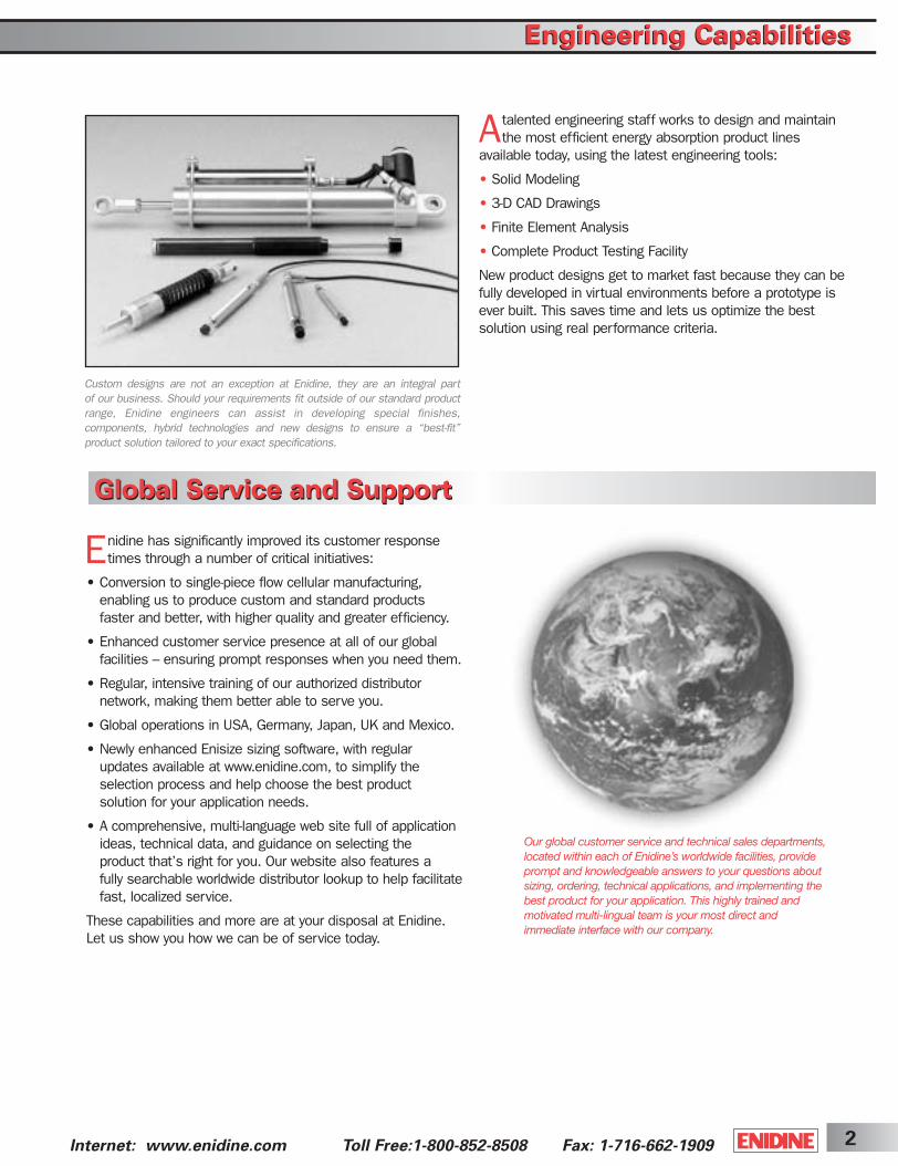
Atalented engineering staff works to design and maintainthe most efficient energy absorption product lines
available today, using the latest engineering tools:
• Solid Modeling
• 3-D CAD Drawings
• Finite Element Analysis
• Complete Product Testing Facility
New product designs get to market fast because they can befully developed in virtual environments before a prototype isever built. This saves time and lets us optimize the best solution using real performance criteria.
Enidine has significantly improved its customer responsetimes through a number of critical initiatives:
• Conversion to single-piece flow cellular manufacturing,enabling us to produce custom and standard products faster and better, with higher quality and greater efficiency.
• Enhanced customer service presence at all of our globalfacilities – ensuring prompt responses when you need them.
• Regular, intensive training of our authorized distributor network, making them better able to serve you.
• Global operations in USA, Germany, Japan, UK and Mexico.
• Newly enhanced Enisize sizing software, with regular updates available at www.enidine.com, to simplify the selection process and help choose the best product solution for your application needs.
• A comprehensive, multi-language web site full of applicationideas, technical data, and guidance on selecting the product that’s right for you. Our website also features a fully searchable worldwide distributor lookup to help facilitatefast, localized service.
These capabilities and more are at your disposal at Enidine.Let us show you how we can be of service today.
Custom designs are not an exception at Enidine, they are an integral part of our business. Should your requirements fit outside of our standard productrange, Enidine engineers can assist in developing special finishes, components, hybrid technologies and new designs to ensure a “best-fit” product solution tailored to your exact specifications.
Our global customer service and technical sales departments,located within each of Enidine’s worldwide facilities, provideprompt and knowledgeable answers to your questions about sizing, ordering, technical applications, and implementing the best product for your application. This highly trained andmotivated multi-lingual team is your most direct and immediate interface with our company.
Global Service and Support
Engineering CapabilitiesEngineering Capabilities
Global Service and Support
ShockCover5-2B 3/31/03 2:28 PM Page 2
Internet: www.enidine.com Toll Free: 1-800-852-8508 Fax: 1-716-662-19093
Overview of Energy Absorption Theory
As companies strive to increase productivity by operatingmachinery at higher speeds, often the results are
increased noise, damage to machinery/products, and excessive vibration. At the same time, safety and machinereliability are decreased. A variety of products are commonlyused to solve these problems. However, they vary greatly in effectiveness and operation. Typical products used includerubber bumpers, springs, cylinder cushions and shockabsorbers. The following illustrations compare how the most common products perform:
All moving objects possess kinetic energy. The amount ofenergy is dependent upon weight and velocity. A mechanicaldevice that produces forces diametrically opposed to thedirection of motion must be used to bring a moving object to rest.
Rubber bumpers and springs, although very inexpensive,have an undesirable recoil effect. Most of the energy absorbed by these at impact is actually stored. This stored energy is returned to the load, producing rebound and the potential for damage to the load or machinery. Rubber bumpers and springs initially provide low resisting force which increases with the stroke.
Cylinder cushions are limited in their range of operation. Most often they are not capable of absorbing energy generated by the system. By design, cushions have a relatively short stroke and operate at low pressures resulting in very low energy absorption. The remaining energy is transferred to the system, causing shock loading and vibration.
Shock absorbers provide controlled, predictable deceleration. These products work by converting kinetic energy to thermal energy. More specifically, motion appliedto the piston of a hydraulic shock absorber pressurizes the fluid and forces it to flow through restricting orifices,causing the fluid to heat rapidly. The thermal energy is then transferred to the cylinder body and harmlessly dissipated to the atmosphere.
The advantages of using shock absorbers include:
1. Longer Machine Life – The use of shock absorbers significantly reduces shock and vibration to machinery. This eliminates machinery damage, reduces downtime and maintenance costs, while increasing machine life.
2. Higher Operating Speeds – Machines can be operated athigher speeds because shock absorbers control or gentlystop moving objects. Therefore, production rates can beincreased.
3. Improved Production Quality – Harmful side effects ofmotion, such as noise, vibration and damaging impacts, aremoderated or eliminated so the quality of production isimproved. Therefore, tolerances and fits are easier to maintain.
4. Safer Machinery Operation – Shock absorbers protectmachinery and equipment operators by offering predictable,reliable and controlled deceleration. They can also bedesigned to meet specified safety standards, when required.
5. Competitive Advantage – Machines become more valuable because of increased productivity, longer life, lowermaintenance costs and safer operation.
Automotive vs. Industrial Shock AbsorbersIt is important to understand the differences that exist between thestandard automotive-style shockabsorber and the industrial shockabsorber.
The automotive style employs thedeflective beam and washer method of orificing. Industrial shock absorbers utilize single orifice, multi-orificeand metering pin configurations. The automotive type maintains a damping force which varies in direct proportionto the velocity of the piston, while the damping force in the industrial type varies in proportion to the square of the piston velocity. In addition, the damping force of the automotive type is independent of the stroke position whilethe damping force associated with the industrial type can bedesigned either dependent or independent of stroke position.
Overview of Energy Absorption Theory
ShockCover5-2B 3/31/03 2:28 PM Page 3

4Internet: www.enidine.com Toll Free:1-800-852-8508 Fax: 1-716-662-1909
Equally as important, automotive-style shock absorbersare designed to absorb only a specific amount of input
energy. This means that, for any given geometric size ofautomotive shock absorber, it will have a limited amount of absorption capability compared to the industrial type. This is explained by observing the structural design of the automotive type and the lower strength of materials commonly used. These materials can withstand the lower pressures commonly found in this type. The industrial shock absorber uses higher strength materials, enablingit to function at higher damping forces.
Adjustment TechniquesA properly adjusted shock absorber safely dissipates energy, reducing damaging shock loads and noise levels.For optimum adjustment setting see useable adjustment setting graphs.Watching and “listening” to a shockabsorber as it functions aids in proper adjustment.
To correctly adjust a shock absorber, set the adjustmentknob at zero (0) prior to system engagement. Cycle themechanism and observe deceleration of the system.
If damping appears too soft (unit strokes with no visualdeceleration and bangs at end of stroke), move indicator tonext largest number. Adjustments must be made in gradualincrements to avoid internal damage to the unit (e.g., adjustfrom 0 to 1, not 0 to 4).
Increase adjustment setting until smooth deceleration orcontrol is achieved and negligible noise is heard when the system starts either to decelerate or comes to rest.
When abrupt deceleration occurs at the beginning of thestroke (banging at impact), the adjustment setting must bemoved to a lower number to allow smooth deceleration.
If the shock absorber adjustment knob is set at the high endof the adjustment scale and abrupt deceleration occurs atthe end of the stroke, a larger unit may be required.
Shock Absorber Performance When Weight or Impact Velocity VaryWhen conditions change from the original calculated data oractual input, a shock absorber’s performance can be greatlyaffected, causing failure or degradation of performance.Variations in input conditions after a shock absorber hasbeen installed can cause internal damage, or at the veryleast, can result in unwanted damping performance.Variations in weight or impact velocity can be seen by examining the following energy curves:
Varying Impact Weight: Increasing the impact weight(impact velocity remains unchanged), without reorificingor readjustment will result in increased damping force at the end of the stroke. Figure 1 depicts this undesirablebottoming peak force. This force is then transferred to themounting structure and impacting load.
Varying Impact Velocity: Increasing impact velocity (weight remains the same) results in a radical change in the resultant shock force. Shock absorbers are velocityconscious products; therefore, the critical relationship toimpact velocity must be carefully monitored. Figure 2 depictsthe substantial change in shock force that occurs when thevelocity is increased. Variations from original design data orerrors in original data may cause damage to mounting structures and systems, or result in shock absorber failure if the shock force limits are exceeded.
Damping ForceMin. Max.
Figure 1
Figure 2
Overview of Energy Absorption TheoryOverview of Energy Absorption Theory
ShockCover5-2B 3/31/03 2:28 PM Page 4

Internet: www.enidine.com Toll Free: 1-800-852-8508 Fax: 1-716-662-19095
Sizing ExamplesSizing Examples
SHOCK ABSORBER SIZINGFollow the next six steps to manually size Enidine shock absorbers:
STEP 1: Identify the following parameters. These must be known for all energyabsorption calculations. Variations or additional information may be required insome cases.A. Weight of the load to be stopped (lbs.).B. Velocity of the load upon impact with the shock absorber (in./sec.).C. External (propelling) forces acting on the load (lbs.), if any.D. Cyclic frequency at which the shock absorber will operate.E. Orientation of the application’s motion (i.e. horizontal, vertical up,
vertical down, inclined, rotary horizontal, rotary vertical up, rotary vertical down).
NOTE: For rotary applications, it is necessary to determine both the radius of gyration (K) and the mass moment of inertia (I). Both of these terms locate themass of a rotating object with respect to the pivot point. It is also necessary todetermine the angular velocity (ω) and the torque (T).
STEP 2: Calculate the kinetic energy of the moving object.
(Note: 772 = 2 x acceleration due to gravity)Utilizing the Product Locators for Shock Absorbers located at the beginningof each product family section, select a model, either adjustable or non-adjustable, with a greater energy per cycle capacity than the value just calculated.
STEP 3: Calculate the work energy input from any external (propelling) forcesacting on the load, using the stroke of the model selected in Step 2.
Caution: The propelling force must not exceed the maximum propelling forcelisted for the model chosen. If the propelling force is too high, select a largermodel and recalculate the work energy.
STEP 4: Calculate the total energy per cycle ET = EK + EW
The model selected must have at least this much energy capacity. If not,select a model with greater energy capacity and return to Step 3.
STEP 5: Calculate the energy that must be absorbed per hour. Even though theshock absorber can absorb the energy in a single impact, it may not be ableto dissipate the heat generated if the cycle rate is too high.
ETC = ET x CThe model selected must have an energy per hour capacity greater than thiscalculated figure. If it is not greater, there are two options:1. Choose another model that has more energy per hour capacity (because
of larger diameter or stroke). Keep in mind that if the stroke changes, youmust return to Step 3.
2. Use an Air/Oil Tank. The increased surface area of the tank and pipingwill increase the energy per hour capacity by 20 percent.
STEP 6: If you have selected an HP, PM, SPM, TK, or PRO Series model, referto the sizing graph(s) in the appropriate series section to determine therequired damping constant. If the point cannot be found in the sizing graph,you must select a larger model or choose a different series. Note that if thestroke changes, you must return to Step 3.If you have selected an adjustable model (OEM, HP or HDA series), refer tothe Useable Adjustment Setting Range graph for the chosen model. Theimpact velocity must fall within the limits shown on the graph.
EK = W x V2
772 EK = I ω2
2(linear) or (rotary)
EW = FD x S EW = T x SRS
(linear) or (rotary)
RATE CONTROL SIZINGFollow the next five steps to manually sizeEnidine rate controls:
STEP 1: Identify the following parameters.These must be known for all rate control calculations. Variations or additional information may be required in some cases.A. Weight of the load to be controlled (lbs.)B. Desired velocity of the load (in/sec.)C. External (propelling) force acting on the
load (lbs.), if any.D. Cyclic frequency at which the rate control
will operate.E. Orientation of the application’s motion
(i.e. horizontal, vertical up, vertical down,inclined, rotary horizontal, rotary verticalup, rotary vertical down.)
F. Damping direction (i.e., tension [T], compression [C] or both [T and C].
G. Required stroke (in.)NOTE: For rotary applications, please submit the application worksheet on page 81 to Enidine for sizing.
STEP 2: Calculate the propelling force at the rate control in each direction damping is required. (See sizing examples on page 10).CAUTION: The propelling force in eachdirection must not exceed the maximum propelling force listed for the chosen model.If the propelling force is too high, select alarger model.
STEP 3: Calculate the total energy per cycleET = EW (tension) + EW (compression)
EW = FD x S
STEP 4: Calculate the total energy per hourETC = ET x C
The model selected must have an energy per hour capacity greater than this calculated figure. If not, choose a modelwith a higher energy per hour capacity.Compare the damping direction, stroke, propelling force, and total energy per hourto the values listed in the Rate ControlsEngineering Data Charts (pages 71-76).
STEP 5: If you have selected a rate control,refer to the sizing graphs in the RateControls section to determine the requireddamping constant.If you have selected an adjustable model(ADA), refer to the Useable AdjustmentSetting Range graph for the chosen model.The desired velocity must fall within the limits shown on the graph.
ShockCover5-2B 3/31/03 2:28 PM Page 5
6Internet: www.enidine.com Toll Free:1-800-852-8508 Fax: 1-716-662-1909
SHOCK ABSORBERS
Sizing ExamplesSizing Examples
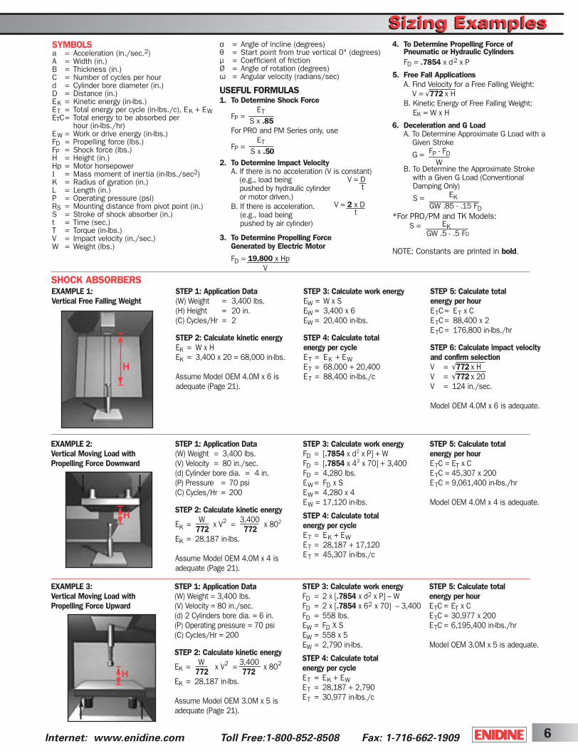
STEP 1: Application Data(W) Weight = 3,400 lbs.(V) Velocity = 80 in./sec.(d) 2 Cylinders bore dia. = 6 in.(P) Operating pressure = 70 psi(C) Cycles/Hr = 200
STEP 2: Calculate kinetic energy
EK = WWW x V2 = 3,400 x 802772 772
EK = 28,187 in-lbs.
Assume Model OEM 3.0M x 5 isadequate (Page 21).
α = Angle of incline (degrees)θ = Start point from true vertical 0˚ (degrees)µ = Coefficient of frictionØ = Angle of rotation (degrees)ω = Angular velocity (radians/sec)
USEFUL FORMULAS1. To Determine Shock Force
FP =ET
S x .85For PRO and PM Series only, use
FP =ET
S x .502. To Determine Impact Velocity
A. If there is no acceleration (V is constant)(e.g., load being pushed by hydraulic cylinder or motor driven.)
B. If there is acceleration. (e.g., load being pushed by air cylinder)
3. To Determine Propelling ForceGenerated by Electric Motor
FD = 19,800 x HpV
SYMBOLSa = Acceleration (in./sec.2) A = Width (in.) B = Thickness (in.) C = Number of cycles per hour d = Cylinder bore diameter (in.) D = Distance (in.)EK = Kinetic energy (in-lbs.)ET = Total energy per cycle (in-lbs./c), EK + EWETC= Total energy to be absorbed per
hour (in-lbs./hr)EW = Work or drive energy (in-lbs.)FD = Propelling force (lbs.)FP = Shock force (lbs.)H = Height (in.)Hp = Motor horsepowerI = Mass moment of inertia (in-lbs./sec2)K = Radius of gyration (in.)L = Length (in.)P = Operating pressure (psi)RS = Mounting distance from pivot point (in.)S = Stroke of shock absorber (in.)t = Time (sec.)T = Torque (in-lbs.)V = Impact velocity (in./sec.)W = Weight (lbs.)
4. To Determine Propelling Force ofPneumatic or Hydraulic CylindersFD = .7854 x d2 x P
5. Free Fall ApplicationsA. Find Velocity for a Free Falling Weight:
V = √772ox HB. Kinetic Energy of Free Falling Weight:
EK = W x H
6. Deceleration and G LoadA. To Determine Approximate G Load with a
Given Stroke
G = FP - FDW
B. To Determine the Approximate Strokewith a Given G Load (ConventionalDamping Only)
S = EKGW .85 - .15 FD
*For PRO/PM and TK Models:S = EK
GW .5 - .5 FD
NOTE: Constants are printed in bold.
V = Dt
V = 2 x Dt
STEP 1: Application Data(W) Weight = 3,400 lbs.(V) Velocity = 80 in./sec.(d) Cylinder bore dia. = 4 in.(P) Pressure = 70 psi(C) Cycles/Hr = 200
STEP 2: Calculate kinetic energy
EK = WWW x V2 = 3,400 x 802
772 772EK = 28,187 in-lbs.
Assume Model OEM 4.0M x 4 isadequate (Page 21).
STEP 3: Calculate work energy FD = [.7854 x d2 x P] + W FD = [.7854 x 42 x 70] + 3,400 FD = 4,280 lbs.EW = FD x SEW = 4,280 x 4 EW = 17,120 in-lbs.
STEP 4: Calculate total energy per cycleET = EK + EWET = 28,187 + 17,120 ET = 45,307 in-lbs./c
STEP 5: Calculate total energy per hour ETC = ET x C ETC = 45,307 x 200 ETC = 9,061,400 in-lbs./hr
Model OEM 4.0M x 4 is adequate.
EXAMPLE 2: Vertical Moving Load withPropelling Force Downward
STEP 3: Calculate work energy FD = 2 x [.7854 x d2 x P] – W FD = 2 x [.7854 x 62 x 70] – 3,400 FD = 558 lbs. EW = FD X S EW = 558 x 5 EW = 2,790 in-lbs.
STEP 4: Calculate total energy per cycleET = EK + EWET = 28,187 + 2,790 ET = 30,977 in-lbs./c
STEP 5: Calculate totalenergy per hour ETC = ET x C ETC = 30,977 x 200 ETC = 6,195,400 in-lbs./hr
Model OEM 3.0M x 5 is adequate.
EXAMPLE 3:Vertical Moving Load withPropelling Force Upward
STEP 1: Application Data (W) Weight = 3,400 lbs.(H) Height = 20 in.(C) Cycles/Hr = 2
STEP 2: Calculate kinetic energy EK = W x H EK = 3,400 x 20 = 68,000 in-lbs.
Assume Model OEM 4.0M x 6 isadequate (Page 21).
STEP 3: Calculate work energyEW = W x SEW = 3,400 x 6 EW = 20,400 in-lbs.
STEP 4: Calculate total energy per cycleET = EK + EWET = 68,000 + 20,400 ET = 88,400 in-lbs./c
STEP 5: Calculate total energy per hourETC= ET x CETC= 88,400 x 2ETC= 176,800 in-lbs./hr
STEP 6: Calculate impact velocityand confirm selectionV = √772ox HV = √772ox 20V = 124 in./sec.
Model OEM 4.0M x 6 is adequate.
EXAMPLE 1: Vertical Free Falling Weight
H
H
H
ShockCover5-2B 3/31/03 2:28 PM Page 6
Internet: www.enidine.com Toll Free: 1-800-852-8508 Fax: 1-716-662-19097
Sizing ExamplesSizing ExamplesAssume Model OEM 2.0M x 2 isadequate (Page 21).EW = FD x SEW = 695 x 2EW = 1,390 in-lbs.
STEP 4: Calculate total energy per cycleET = EK + EWET= 933 + 1,390ET = 2,323 in-lbs./c
STEP 5: Calculate total energy per hourETC = ET x CETC = 2,323 x 100ETC = 232,300 in-lbs./hr
Model OEM 2.0M x 2 is adequate.
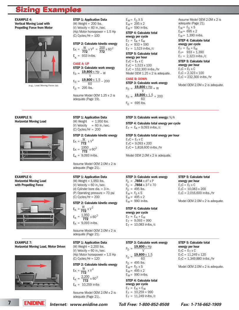
STEP 1: Application Data(W) Weight = 1,950 lbs.(V) Velocity = 60 in./sec.(C) Cycles/Hr = 200
STEP 2: Calculate kinetic energy
EK = WW x V2772
EK = 1950 x 602772
EK = 9,093 in-lbs.
Assume Model OEM 2.0M x 2 isadequate (Page 21).
STEP 3: Calculate work energy: N/A
STEP 4: Calculate total energy per cycle ET = EK = 9,093 in-lbs./c
STEP 5: Calculate total energy per hourETC = ET x C ETC = 9,093 x 200 ETC = 1,818,600 in-lbs./hr
Model OEM 2.0M x 2 is adequate.
EXAMPLE 5: Horizontal Moving Load
STEP 1: Application Data(W) Weight = 1,950 lbs.(V) Velocity = 60 in./sec.(d) Cylinder bore dia. = 3 in.(P) Operating pressure = 70 psi(C) Cycles/Hr = 200
STEP 2: Calculate kinetic energy
EK = WW x V2772
EK = 1,950 x 602772
EK = 9,093 in-lbs.
Assume Model OEM 2.0M x 2 isadequate (Page 21).
STEP 3: Calculate work energyFD = .7854 x d2 x P FD = .7854 x 3 2 x 70 FD = 495 lbs. EW = FD x S EW = 495 x 2 EW = 99O in-lbs.
STEP 4: Calculate total energy per cycleET = EK + EWET = 9,093 + 990 ET = 10,083 in-lbs./c
STEP 5: Calculate total energy per hourETC = ET x C ETC = 10,083 x 200 ETC = 2,016,600 in-lbs./hr
Model OEM 2.0M x 2 is adequate.
EXAMPLE 6:Horizontal Moving Load with Propelling Force
STEP 1: Application Data(W) Weight = 2,200 lbs.(V) Velocity = 60 in./sec.(Hp) Motor horsepower = 1.5 Hp(C) Cycles/Hr = 120
STEP 2: Calculate kinetic energy
EK = WW x V2772
EK = 2,200 x 602772
EK = 10,259 in-lbs
Assume Model OEM 2.0M x 2 isadequate (Page 21).
STEP 3: Calculate work energy
FD = 19,800ox HpV
FD = 19,800ox 1.560
FD = 495 lbs.EW = FD x S EW = 495 x 2EW = 990 in-lbs.
STEP 4: Calculate total energy per cycle ET = EK + EWET = 10,259 + 990 ET = 11,249 in-lbs./c
STEP 5: Calculate total energy per hourETC = ET x C ETC = 11,249 x 120 ETC = 1,349,880 in-lbs./hr
Model OEM 2.0M x 2 is adequate.
EXAMPLE 7: Horizontal Moving Load, Motor Driven
STEP 1: Application Data(W) Weight = 200 lbs.(V) Velocity = 60 in./sec.(Hp) Motor horsepower = 1.5 Hp(C) Cycles/Hr = 100
STEP 2: Calculate kinetic energy
EK = W x V2 = 200 x 602772 772
EK
= 933 in-lbs.
CASE A: UPSTEP 3: Calculate work energy
FD = 19,800 x Hp – WV
FD = 19,800 x 1.5 – 20060
FD = 295 lbs.
Assume Model OEM 1.25 x 2 is adequate (Page 19).
EW = FD X SEW = 295 x 2EW = 590 in-lbs.
STEP 4: Calculate total energy per cycleET = EK + EWET = 933 + 590ET = 1,523 in-lbs./c
STEP 5: Calculate total energy per hourETC = ET x CETC = 1,523 x 100ETC = 152,300 in-lbs./hrModel OEM 1.25 x 2 is adequate.
CASE B: DOWNSTEP 3: Calculate work energy
FD = 19,800 x Hp + WV
FD = 19,800 x 1.5 + 20060
FD = 695 lbs.
EXAMPLE 4: Vertical Moving Load withPropelling Force from Motor
(e.g., Load Moving Force Up)
ShockCover5-2B 3/31/03 2:28 PM Page 7

8Internet: www.enidine.com Toll Free:1-800-852-8508 Fax: 1-716-662-1909
Sizing ExamplesSizing Examples
STEP 1: Application Data(W) Weight = 50 lbs.(ω) Angular velocity = 2.5 rad./sec.(T) Torque = 100 in-lbs.(RS) Mounting radius = 20 in.(A) Width = 40 in.(B) Thickness = .5 in.(C) Cycles/Hr = 250
STEP 2: Calculate kinetic energyK = .289 x √4 x A2 + B2
K = .289 x √4 x 402 +.52
K = 23.12
I = W x K2
386
STEP 1: Application Data(W) Weight = 1,765 lbs.(V) Velocity = 47 in./sec.(µ) Coefficient of Friction = .3(C) Cycles/Hr = 120
STEP 2: Calculate kinetic energy
EK = 1W x V2772
EK = 1,765 x 472772
EK = 5,050 in-lbs.
Assume Model PM 2050 is adequate (Page 37).
STEP 3: Calculate work energy FD = W x µFD = 1,765 x .3 FD = 530 lbs. EW = FD x S EW = 530 x 2 EW = 1,060 in-lbs.
STEP 4: Calculate total energy per cycleET = EK + EWET = 5,050 + 1,060 ET = 6,110 in-lbs./c
STEP 5: Calculate total energy per hour ETC = ET x C ETC = 6,110 x 120 ETC = 773,200 in-lbs./hr
From PM sizing graph, Model PM2050-2 is adequate.
EXAMPLE 8:Horizontal Moving Load Propelled by Drive Rollers (Chain/Belt Drive or Conveyor Belt)
STEP 1: Application Data(W) Weight = 550 lbs.(H) Height = 8 in.(α) Angle of incline = 30˚(C) Cycles/Hr = 250
STEP 2: Calculate kinetic energyEK = W x H EK = 550 x 8 EK = 4,400 in-lbs.
Assume Model OEM 1.5M x 3 isadequate (Page 21).
STEP 3: Calculate work energyFD = W x Sin αFD = 550 x .5FD = 275 lbs.EW = FD x SEW = 275 x 3EW = 825 in-lbs.
STEP 4: Calculate total energy per cycleET = EK + EWET = 4,400 + 825ET = 5,225 in-lbs./c
STEP 5: Calculate total energy per hourETC = ET x C ETC = 5,225 x 250 ETC = 1,306,250 in-lbs./hr
STEP 6: Calculate impact velocityand confirm selectionV = √772xx HV = √772xx 8 = 79 in./sec.
Model OEM 1.5M x 3 is adequate.
EXAMPLE 9: Free Moving Load Down an Inclined Plane
STEP 1: Application Data(W) Weight = 200 lbs.(ω) Angular velocity = 1.5 rad./sec.(T) Torque = 1,065 in-lbs.(K) Radius of gyration = 15 in.(RS) Mounting radius = 20 in.(C) Cycles/Hr = 120
STEP 2: Calculate kinetic energy
I = W x K2386
I = 200 x 152386
I = 117 in-lbs./sec.2
EK = IIx ω2
2
EK = 117 x 1.52
2EK = 132 in-lbs.Assume Model STH .5M is adequate(Page 34).
STEP 3 Calculate work energy
FD = TRS
FD = 1,06520
FD = 53 lbs. EW = FD X S EW = 53 X .5 EW = 27 in-lbs.
STEP 4: Calculate total energy per cycle ET = EK + EWET = 132 + 27 ET = 159 in-lbs./c
STEP 5: Calculate total energy per hour ETC = ET X C ETC = 159 X 120 ETC = 19,080 in-lbs./hr
Model STH .5M is adequate.
EXAMPLE 10:Horizontal Rotating Mass
I = 50 x 23.122
386I = 69 in-lbs./sec.2
EK = I x ω2
2
EK = 69 x 2.52
2EK = 216 in-lbs.Assume Model OEM .5 is adequate(Page 19).
STEP 3: Calculate work energy
FD = TRS
FD = 100 20
FD = 5 lbs.EW = FD x S = 5 x .5 = 2.5 in-lbs.
STEP 4: Calculate total energy per cycleET = EK + EW = 216 + 2.5 =
218.5 in-lbs./c
STEP 5: Calculate total energy per hourETC = ET x C = 218.5 x 250 =
54,625 in-lbs./hr
STEP 6: Calculate impact velocityand confirm selectionV = RS x ω = 20 x 2.5 = 50 in./sec.
Model OEM .5 is adequate.
EXAMPLE 11: Horizontal Rotating Door
HD
αα
K
W
Rs
ωω
A
B
Rs
T
ωω
ShockCover5-2B 3/31/03 2:28 PM Page 8

Internet: www.enidine.com Toll Free: 1-800-852-8508 Fax: 1-716-662-19099
Sizing ExamplesSizing Examples
STEP 2: Calculate kinetic energyK = .289 x √4 x L2 + B2
K = .289 x √4 x 242 + 2.52 = 13.89
I = 5W x K2 = 540 x 13.89386 386
I = 270 in-lbs./sec.2
EK= I x ω2= 270 x 3.52
= 1,653 in-lbs.2 2
Assume Model OEM 1.5M x 2 is adequate (Page 21).
In this case, the mass moment of inertia of the table and the massmoment of inertia of the load on thetable must be calculated.KTable =Table Radius x .707KTable =10 x .707 = 7.07 in.
ITable = W x K2 Table
386
ITable = 440 x 7.072 = 57 in-lbs./sec.2386
ILoad = W1 x K2 Load386
ILoad = 110 x 82 = 18 in-lbs./sec.2386
EK = (ITable + ILoad) x ω2
2
EK = (57 + 18) x 1.0472= 41 in-lbs.
2Assume Model PM 50 is adequate(Page 35).
STEP 1: Application Data(W) Weight = 110 lbs.(ω) Angular velocity = 2 rad./sec.(T) Torque = 3,100 in-lbs.(θ) Starting point of load from
true vertical = 20˚(Ø) Angle of rotation at impact = 30˚(KLoad) Radius of gyration = 24 in.(RS) Mounting radius = 16 in.(C) Cycles/Hr = 1
STEP 2: Calculate kinetic energy
I = 1W0 x K2 = 110 x 242
386 386I = 164 in-lbs-sec2
EK = I x ω2
2EK = 164 x 22
2EK = 328 in-lbs.
Assume Model OEM 1.0 is adequate(Page 19).
STEP 1: Application Data(W) Weight = 440 lbs.(W1) Installed load = 110 lbs.Rotational speed = 10 RPM(T) Torque = 2,200 in-lbs.Rotary table dia. = 20 in.(KLoad) Radius of gyration = 8 in.(RS) Mounting radius = 8.86 in.(C) Cycles/Hr = 1(ω) Direction
Step 2: Calculate kinetic energyTo convert RPM to rad./sec., multiplyby .1047ω = RPM x .1047 = 10 x .1047
= 1.047 rad./sec.
I = W x K2386
STEP 3: Calculate work energy
FD = T = 2,200 = 248 lbs.RS 8.86
EW = FD x S = 248 x .875 = 217 in-lbs.
STEP 4: Calculate total energy per cycle
ET = EK + EW = 41 + 217 = 258 in-lbs./c
STEP 5: Calculate total energy per hour: not applicable, C=1
STEP 6: Calculate impact velocityand confirm selectionV = RS x ω = 8.86 x 1.047 =
9 in./sec.
From PM Sizing Graph. Model PM 50-3 is adequate.
EXAMPLE 12: Horizontal Moving Load, Rotary Table Motor Driven withAdditional Load Installed
CASE ASTEP 3: Calculate work energy
FD = T – (W x K x Sin Ø)RS
FD = 3,100 – (110 x 24 x .5)16
FD = 111 lbs.EW= FD x S = 111 x 1 = 111 in-lbs.
STEP 4: Calculate total energy per cycle ET = EK + EW = 328 + 111 ET = 439 in-lbs./c
STEP 5: Calculate total energy per hour: not applicable, C=1
STEP 6: Calculate impact velocityand confirm selectionV = RSx ω = 16 x 2 = 32 in./sec.Model OEM 1.0 is adequate.
CASE BSTEP 3: Calculate work energy
FD = T + (W x K x Sin Ø)RS
FD = 3,100 + (110 x 24 x .5)16
FD = 276 lbs.EW= FD x S = 276 x 1 = 276 in-lbs.
STEP 4: Calculate total energy per cycleET = EK + EW = 328 + 276ET = 604 in-lbs./c
STEP 5: Calculate total energy per hour: not applicable, C=1
STEP 6: Calculate impact velocityand confirm selection. V = RS x ω= 16 x 2 = 32 in./sec.
Model OEM 1.0 is adequate.
EXAMPLE 13: Vertical Motor Driven Rotating Arm with Attached Load –This example illustrates calculations for two conditions: CASE A–Load Opposing GravityCASE B–Load Aided by Gravity
STEP 1: Application Data(W) Weight = 540 lbs.(ω) Angular velocity = 3.5 rad./sec.(T) Torque = 250 in-lbs.(θ) Starting point of load from
true vertical = 20˚(Ø) Angle of rotation at impact = 50°(RS) Mounting radius = 20 in.(B) Thickness = 2.5 in.(L) Length = 24 in.(C) Cycles/Hr = 1 STEP 3: Calculate work energy
FD = T + (W x K x Sin (θθ+ Ø))RS
FD = 250 + (540 x 13.89 x Sin (20˚ + 50˚))20
FD = 365 lbs.EW= FD x S = 365 x 2 = 730 in-lbs.
EXAMPLE 14: Vertical Rotating Beam
STEP 4: Calculate total energy per cycleET = EK + EW = 1,653 + 730 =
2,383 in-lbs./c
STEP 5: Calculate total energy per hour: not applicable, C=1
STEP 6: Calculate impact velocityand confirm selectionV = RS x ω = 20 x 3.5 = 70 in./sec.
Model OEM 1.5M x 2 is adequate.
K
d
Rs
T
K
T
Ø
Rs
ωω
L
B
Rsωω
T
ShockCover5-2B 3/31/03 2:28 PM Page 9

10Internet: www.enidine.com Toll Free:1-800-852-8508 Fax: 1-716-662-1909
RATE CONTROLS
Sizing ExamplesSizing Examples
I = 1W0 x K2 = 2,000 x 34.682 in.386 386
I = 6,232 in-lbs./sec.2
EK= I x ω2= 6,232 x 22
2 2EK= 12,464 in-lbs.Assume Model OEM 3.0M x 2 is adequate (Page 21).
STEP 3: Calculate work energy
T = 19,800 x Hpω
T = 19,800 x .25 = 2,475 in-lbs.2
FD = T + (W x K x Sin (θ + Ø))RS
FD = 2,475 + (2,000 x 34.68 x Sin (30˚ + 60 )̊)30
FD = 2,395 lbs.EW = FD x S = 2,395 x 2 = 4,790 in-lbs.
STEP 1: Application Data(W) Weight = 2,000 lbs.(ω) Angular velocity = 2 rad./sec.(Hp) Motor horsepower = .25 Hp(θ) Starting point of load from
true vertical = 30°(Ø) Angle of rotation at impact = 60°(RS) Mounting radius = 30 in.(A) Width = 60 in.(B) Thickness = 1 in.(C) Cycle/Hr = 1
STEP 2: Calculate kinetic energyK = .289 x √4 x A2 + B2
K = .289 x √4 x 602 + 12 =34.68 in.
STEP 4: Calculate total energy per cycleE T = EK + EW = 12,464 + 4,790
= 17,254 in-lbs./c
STEP 5: Calculate total energy per hour: not applicable, C=1
STEP 6: Calculate impact velocityand confirm selection V = RS x ω = 30 x 2 = 60 in./sec.
Model OEM 3.0M x 2 is adequate.
EXAMPLE 15:Vertical Rotating Lid
STEP 1: Application Data(W) Weight = 100 lbs.Damping direction (T, C or T and C) = T(d) Cylinder bore dia = 2 in.(S) Stroke = 4 in.(P) Pressure = 65 psi(V) Velocity = 6 in./sec.(C) Cycles/Hr = 10
STEP 2: Calculate propelling force FD = [.7854 x d2 x P] FD = [.7854 x 22 x 65] + 100FD = 304 lbs.
STEP 3: Calculate total energy per cycleET = FD x SET = 304 x 4ET = 1,216 in-lbs./c
STEP 4: Calculate total energy per hourETC = ET x CETC = 1,216 x 10 = 12,160 in-lbs./hr
STEP 5: Confirm selection.
Model ADA 510 TP is selected.
EXAMPLE 17:Vertical Moving Load withPropelling Force Downward
EXAMPLE 16:Horizontal Moving Load withPropelling Force
STEP 1: Application Data(W) Weight = 50 lbs.Damping direction (T, C or T and C) = T and C(S) Stroke = 4 in.(d) Cylinder bore dia = 2 in.(d1) Cylinder rod dia = .5 in.(P) Pressure = 70 psi(V) Velocity = 6 in./sec.(C) Cycles/Hr = 200
STEP 2: Calculate propellingforce (tension)FD = .7854 x d2 x PFD = .7854 x 22 x 70FD = 220 lbs. (tension)FD = .7854 x (d2 - d1
2) x P (compression)
FD = .7854 x (22 - .52) x 70FD = 206 lbs. (compression)
STEP 3: Calculate total energy per cycleEW = FD x S (tension)EW = 220 x 4EW = 880 in-lbs./c (tension) EW = FD x S (compression)EW = 206 x 4EW = 824 in-lbs./c (compression)ET = EW (tension) + EW (compression)ET = 880 + 824ET = 1,704 in-lbs./c
STEP 4: Calculate total energy per hourETC = ET x CETC = 1,704 x 200ETC = 340,800 in-lbs./hr
STEP 5: Confirm selection.
Model ADA 510 TC is selected.
A
T
B
Rs
Ø
Enidine Rate Control
Enidine Rate Control
ShockCover5-2B 3/31/03 2:28 PM Page 10
Internet: www.enidine.com Toll Free: 1-800-852-8508 Fax: 1-716-662-190911
Typical Crane Application Sizing ExamplesTypical Crane Application Sizing Examples
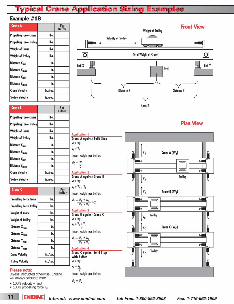
Front View
Crane A (WA)
Crane B (WB)
Crane C (WC)
Trolley
Trolley
Trolley
VA
VA
VB
VB
VC
VC
Plan View
Example #18
Please note:Unless instructed otherwise, Enidinewill always calculate with:• 100% velocity v, and• 100% propelling force FD
Application 1Crane A against Solid StopVelocity:
Vr = VA
Impact weight per buffer:
WD = W2
Application 2Crane A against Crane BVelocity:
Vr = VA + VB
Impact weight per buffer:
WD = WA • WB 2WA + WB
Application 3Crane B against Crane CVelocity:Vr = VB + VC
2Impact weight per buffer:
WD = WB • WCWB + WC
Application 4Crane C against Solid Stop with BufferVelocity:Vr = VC
2Impact weight per buffer:
WD = WC
..
Velocity of Trolley
Total Weight of Crane
Weight of Trolley
Distance X
Span Z
Rail X Rail YLoad
Distance Y
Crane A Per Buffer
Propelling Force Crane lbs.
Propelling Force Trolley lbs.
Weight of Crane lbs.
Weight of Trolley lbs.
Distance Xmin in.
Distance Xmax in.
Distance Ymin in.
Distance Ymax in.
Crane Velocity in./sec.
Trolley Velocity in./sec.
Crane B Per Buffer
Propelling Force Crane lbs.
Propelling Force Trolley lbs.
Weight of Crane lbs.
Weight of Trolley lbs.
Distance Xmin in.
Distance Xmax in.
Distance Ymin in.
Distance Ymax in.
Crane Velocity in./sec.
Trolley Velocity in./sec.
Crane C Per Buffer
Propelling Force Crane lbs.
Propelling Force Trolley lbs.
Weight of Crane lbs.
Weight of Trolley lbs.
Distance Xmin in.
Distance Xmax in.
Distance Ymin in.
Distance Ymax in.
Crane Velocity in./sec.
Trolley Velocity in./sec.
ShockCover5-2B 3/31/03 2:28 PM Page 11
12Internet: www.enidine.com Toll Free:1-800-852-8508 Fax: 1-716-662-1909
Typical Crane Application Sizing ExamplesTypical Crane Application Sizing Examples
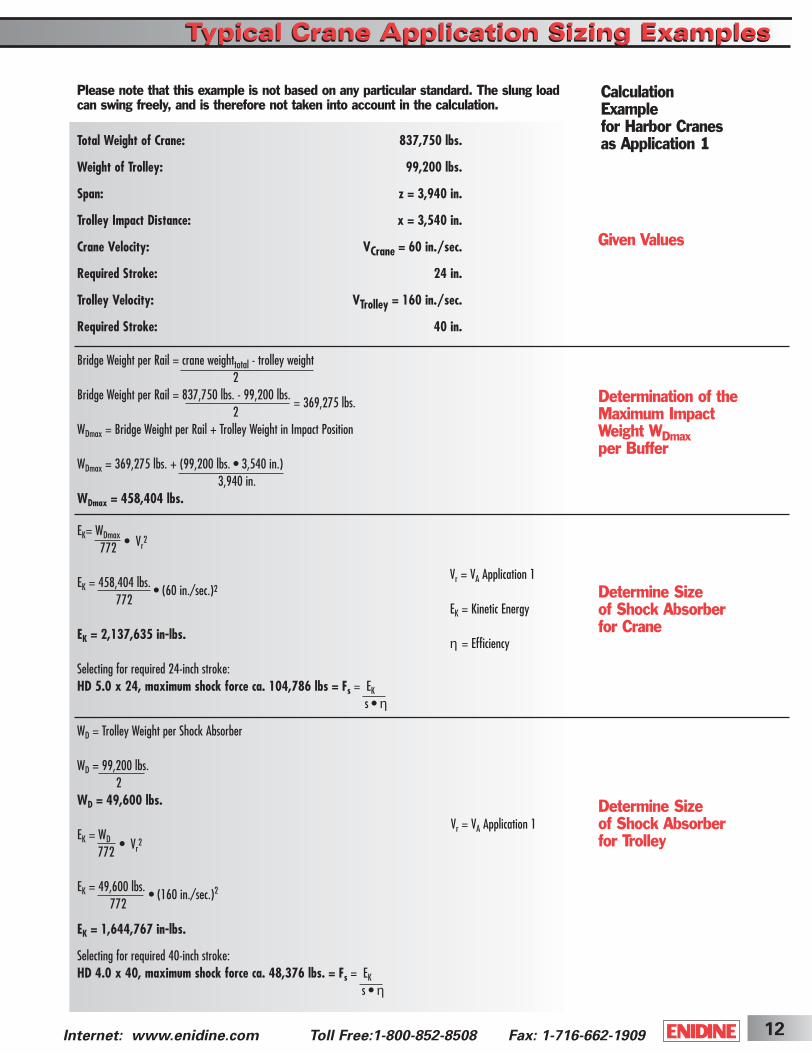
Please note that this example is not based on any particular standard. The slung loadcan swing freely, and is therefore not taken into account in the calculation.
Total Weight of Crane: 837,750 lbs.
Weight of Trolley: 99,200 lbs.
Span: z = 3,940 in.
Trolley Impact Distance: x = 3,540 in.
Crane Velocity: VCrane = 60 in./sec.
Required Stroke: 24 in.
Trolley Velocity: VTrolley = 160 in./sec.
Required Stroke: 40 in.
Bridge Weight per Rail = crane weighttotal - trolley weight2
Bridge Weight per Rail = 837,750 lbs. - 99,200 lbs. = 369,275 lbs.
2WDmax = Bridge Weight per Rail + Trolley Weight in Impact Position
WDmax = 369,275 lbs. + (99,200 lbs. • 3,540 in.)3,940 in.
WDmax = 458,404 lbs.
EK= WDmax • Vr2
772
EK = 458,404 lbs. • (60 in./sec.)2
772
EK = 2,137,635 in-lbs.
Selecting for required 24-inch stroke:HD 5.0 x 24, maximum shock force ca. 104,786 lbs = Fs = EK
s • η
WD = Trolley Weight per Shock Absorber
WD = 99,200 lbs.2
WD = 49,600 lbs.
EK = WD • Vr2
772
EK = 49,600 lbs.• (160 in./sec.)2
772
EK = 1,644,767 in-lbs.
Selecting for required 40-inch stroke:HD 4.0 x 40, maximum shock force ca. 48,376 lbs. = Fs = EK
s • η
Determination of theMaximum ImpactWeight WDmaxper Buffer
Determine Sizeof Shock Absorber for Crane
Determine Sizeof Shock Absorber for Trolley
Given Values
CalculationExamplefor Harbor Cranesas Application 1
Vr = VA Application 1
EK = Kinetic Energy
η = Efficiency
Vr = VA Application 1
ShockCover5-2B 3/31/03 2:28 PM Page 12
Internet: www.enidine.com Toll Free: 1-800-852-8508 Fax: 1-716-662-190913
To Ensure Correct Sizing:If shock absorbers are used at less than 5% of their maximum rated energy per cycle (less than 10% for HDAand HP Series models), a smaller shock absorber should be used. If the shock absorber continually bottoms, verifysizing data.
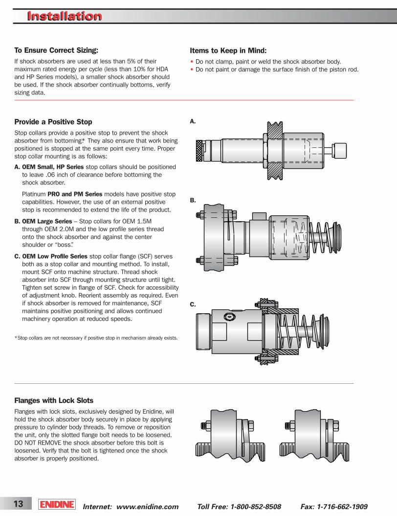
Provide a Positive StopStop collars provide a positive stop to prevent the shockabsorber from bottoming*. They also ensure that work beingpositioned is stopped at the same point every time. Properstop collar mounting is as follows:
A. OEM Small, HP Series stop collars should be positionedto leave .06 inch of clearance before bottoming theshock absorber.
Platinum PRO and PM Series models have positive stopcapabilities. However, the use of an external positive stop is recommended to extend the life of the product.
B. OEM Large Series – Stop collars for OEM 1.5M through OEM 2.0M and the low profile series thread onto the shock absorber and against the center shoulder or “boss”.
C. OEM Low Profile Series stop collar flange (SCF) servesboth as a stop collar and mounting method. To install,mount SCF onto machine structure. Thread shockabsorber into SCF through mounting structure until tight.Tighten set screw in flange of SCF. Check for accessibilityof adjustment knob. Reorient assembly as required. Evenif shock absorber is removed for maintenance, SCF maintains positive positioning and allows continuedmachinery operation at reduced speeds.
*Stop collars are not necessary if positive stop in mechanism already exists.
A.
B.
C.
Items to Keep in Mind:• Do not clamp, paint or weld the shock absorber body. • Do not paint or damage the surface finish of the piston rod.
Flanges with Lock SlotsFlanges with lock slots, exclusively designed by Enidine, willhold the shock absorber body securely in place by applyingpressure to cylinder body threads. To remove or repositionthe unit, only the slotted flange bolt needs to be loosened.DO NOT REMOVE the shock absorber before this bolt is loosened. Verify that the bolt is tightened once the shockabsorber is properly positioned.
InstallationInstallation
ShockCover5-2B 3/31/03 2:28 PM Page 13
14Internet: www.enidine.com Toll Free:1-800-852-8508 Fax: 1-716-662-1909
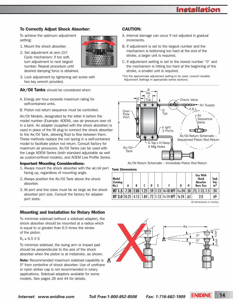
To Correctly Adjust Shock Absorber:To achieve the optimum adjustmentsetting:
1. Mount the shock absorber.
2. Set adjustment at zero (0)*.Cycle mechanism; if too soft, turn adjustment to next largest number. Repeat procedure untildesired damping force is obtained.
3. Lock adjustment by tightening set screw with hex key wrench provided.
Use WithModel Shock Tank(Catalog Absorber Vol.No.) A B C D E F G H Bore Size in3
RT 1.5 7.38 2.88 1.25 .59 1.13 3⁄8-18 NPT 5⁄16-24 .50 .75, 1.13, 1.5 24RT 2.0 10.25 4.13 1.84 .72 1.13 3⁄4-14 NPT 3⁄8-24 .63 2.0 69
CAUTION:A. Internal damage can occur if not adjusted in gradual
increments.
B. If adjustment is set to the largest number and the mechanism is bottoming too hard at the end of the stroke, a larger unit is required.
C. If adjustment setting is set to the lowest number “0” andthe mechanism is hitting too hard at the beginning of thestroke, a smaller unit is required.
*For the approximate adjustment setting to be used, consult Useable Adjustment Settings in appropriate series sections.
Mounting and Installation for Rotary MotionTo minimize sideload (without a sideload adapter), theshock absorber should be mounted at a radius whichis equal to or greater than 6.5 times the stroke of the piston.
Rs ≥ 6.5 X S
To minimize sideload, the swing arm or impact padshould be perpendicular to the axis of the shock absorber when the piston is at midstroke, as shown.
Note: Recommended maximum sideload capability is5° from centerline of shock absorber. Use of urethaneor nylon striker cap is not recommended in rotaryapplications. Sideload adapters available for somemodels. See pages 26 and 44 for details.
Air/Oil Tanks should be considered when:
A. Energy per hour exceeds maximum rating for self-contained units.
B. Piston rod return sequence must be controlled.
Air/Oil Models, designated by the letter A before themodel number (Example: AOEM), use air pressure over oilin a tank. An adapter (supplied with the shock absorber) isused in place of the fill plug to connect the shock absorberto the Air/Oil Tank, allowing fluid to flow between them.These methods replace the coil spring in a self-containedmodel to facilitate piston rod return. Consult factory formaximum air pressures. Air/Oil Tanks can be used withthe Large AOEM Series (both standard adjustable as wellas custom-orificed models), and AOEM Low Profile Series.
Important Mounting Considerations:1. Always mount the shock absorber with the air/oil port
facing up, regardless of mounting angle.
2. Always position the Air/Oil Tank above the shock absorber.
3. All port and line sizes must be as large as the shock absorber port size. Consult the factory for adapter port sizes.
All dimensions in inches.
Tank Dimensions
B Sq.C
Typ.E
OverFlowPort
Air/OilTank
G Tap x H Deep4 Mtg Holes
Air/Oil Return Schematic – Immediate Piston Rod Return
Air/Oil Return Schematic –Sequenced Piston Rod Return
Air SequenceValve
Air SupplyF.R.L.D
Typ.
A
Check Valve
F NPT2 Ports
5°
5°
S2S2
Rs
X
InstallationInstallation
ShockCover5-2B 3/31/03 2:28 PM Page 14
Internet: www.enidine.com Toll-Free: 1-800-852-8508 Fax: 1-716-662-190915
AD
JUSTA
BLE
S
Features and Benefits
Adjustable design lets you “fine-tune” your desireddamping and lock the numbered adjustment setting.
Internal orifice design provides deceleration with themost efficient damping characteristics, resulting inthe lowest reaction forces in the industry.
Threaded cylinders provide mounting flexibility and increased surface area for improved heat dissipation.
Incorporated optional fluids and seal packages canexpand the standard operating temperature rangefrom (15 to 180°F) to (–30 to 210°F).
A select variety of surface finishes maintains original quality appearance and provides the longest corrosion resistance protection.
Operational parameters can be expanded throughthe use of Enidine’s Low Range and HighPerformance products.
Fully field repairable units are available in bore sizes of .75 inches and larger.
ISO quality standards result in reliable, long-life operation.
Custom orificed non-adjustable units (CBOEM) are available to meet specific application requirements.
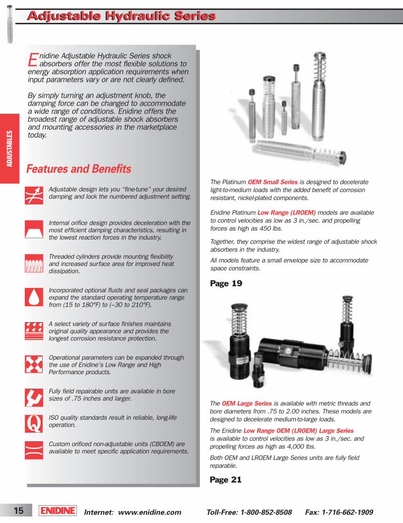
E nidine Adjustable Hydraulic Series shockabsorbers offer the most flexible solutions to
energy absorption application requirements wheninput parameters vary or are not clearly defined.
By simply turning an adjustment knob, the damping force can be changed to accommodatea wide range of conditions. Enidine offers thebroadest range of adjustable shock absorbersand mounting accessories in the marketplacetoday.
The OEM Large Series is available with metric threads and bore diameters from .75 to 2.00 inches. These models aredesigned to decelerate medium-to-large loads.
The Enidine Low Range OEM (LROEM) Large Seriesis available to control velocities as low as 3 in./sec. and propelling forces as high as 4,000 lbs.
Both OEM and LROEM Large Series units are fully field reparable.
Page 21
The Platinum OEM Small Series is designed to decelerate light-to-medium loads with the added benefit of corrosion resistant, nickel-plated components.
Enidine Platinum Low Range (LROEM) models are available to control velocities as low as 3 in./sec. and propelling forces as high as 450 lbs.
Together, they comprise the widest range of adjustable shockabsorbers in the industry.
All models feature a small envelope size to accommodatespace constraints.
Page 19
Adjustable Hydraulic SeriesAdjustable Hydraulic Series
ShockCover5-2B 3/31/03 2:29 PM Page 15
16Internet: www.enidine.com Toll-Free: 1-800-852-8508 Fax: 1-716-662-1909
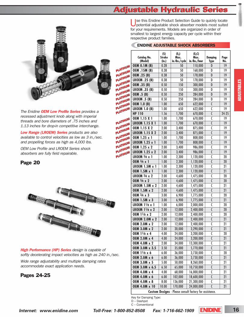
The Enidine OEM Low Profile Series provides a recessed adjustment knob along with imperial threads and bore diameters of .75 inches and 1.13 inches for drop-in competitive interchange.
Low Range (LROEM) Series products are alsoavailable to control velocities as low as 3 in./sec. and propelling forces as high as 4,000 lbs.
OEM Low Profile and LROEM Series shock absorbers are fully field repairable.
Page 20
High Performance (HP) Series design is capable of softly decelerating impact velocities as high as 240 in./sec.
Wide range adjustability and multiple damping rates accommodate exact application needs.
Pages 24-25
AD
JUSTA
BLE
S
Adjustable Hydraulic SeriesAdjustable Hydraulic Series
ENIDINE ADJUSTABLE SHOCK ABSORBERS
Use this Enidine Product Selection Guide to quickly locatepotential adjustable shock absorber models most suited
for your requirements. Models are organized in order ofsmallest to largest energy capacity per cycle within theirrespective product families.
Key for Damping Type:D – DashpotC – Conventional
(S) (ET) (ETC)Catalog No. Stroke Max. Max. Damping Page
(Model) (in.) in.-lbs./cycle in.-lbs./hour Type No.OEM 0.1M (B) 0.28 50 110,000 D 19OEM .15M (B) 0.38 50 168,000 D 19OEM .25 (B) 0.38 50 178,000 D 19LROEM .25 (B) 0.38 50 178,000 D 19OEM .35 (B) 0.50 150 300,000 D 19LROEM .35 (B) 0.50 150 300,000 D 19OEM .5 (B) 0.50 250 284,000 D 19LROEM .5 (B) 0.50 250 284,000 D 19OEM 1.0 (B) 1.00 650 622,000 C 19LROEM 1.0 (B) 1.00 650 622,000 C 19HP 110 1.56 1,700 670,000 C 24-25OEM 1.15 X 1 1.00 1,700 670,000 C 19LROEM 1.15 X 1 1.00 1,700 670,000 C 19OEM 1.15 X 2 2.00 3,400 875,000 C 19LROEM 1.15 X 2 2.00 3,400 875,000 C 19OEM 1.25 x 1 1.00 1,700 808,000 C 19LROEM 1.25 x 1 1.00 1,700 808,000 C 19OEM 1.25 x 2 2.00 3,400 986,000 C 19LROEM 1.25 x 2 2.00 3,400 986,000 C 19LROEM 3⁄4 x 1 1.00 2,300 1,120,000 C 20OEM 3⁄4 x 1 1.00 2,300 1,120,000 C 20LROEM 1.5M x 1 1.00 2,300 1,120,000 C 21OEM 1.5M x 1 1.00 2,300 1,120,000 C 21LROEM 3⁄4 x 2 2.00 4,600 1,475,000 C 20OEM 3⁄4 x 2 2.00 4,600 1,475,000 C 20LROEM 1.5M x 2 2.00 4,600 1,475,000 C 21OEM 1.5M x 2 2.00 4,600 1,475,000 C 21OEM 3⁄4 x 3 3.00 6,900 1,775,000 C 20OEM 1.5M x 3 3.00 6,900 1,775,000 C 21LROEM 11⁄8 x 1 1.00 6,000 2,000,000 C 20LROEM 11⁄8 x 2 2.00 12,000 2,400,000 C 20OEM 11⁄8 x 2 2.00 12,000 2,400,000 C 20LROEM 2.0M x 2 2.00 12,000 2,400,000 C 21OEM 2.0M x 2 2.00 12,000 2,400,000 C 21OEM 3.0M x 2 2.00 20,000 3,290,000 C 21OEM 11⁄8 x 4 4.00 24,000 3,200,000 C 20OEM 2.0M x 4 4.00 24,000 3,200,000 C 21OEM 4.0M x 2 2.00 34,000 13,300,000 C 21OEM 3.0M x 3.5 3.50 35,000 5,770,000 C 21OEM 11⁄8 x 6 6.00 36,000 3,730,000 C 20OEM 2.0M x 6 6.00 36,000 3,730,000 C 21OEM 3.0M x 5 5.00 50,000 8,260,000 C 21OEM 3.0M x 6.5 6.50 65,000 10,750,000 C 21OEM 4.0M x 4 4.00 68,000 16,000,000 C 21OEM 4.0M x 6 6.00 102,000 18,600,000 C 21OEM 4.0M x 8 8.00 136,000 21,300,000 C 21OEM 4.0M x 10 10.00 170,000 24,000,000 C 21
Custom Designs - Please consult factory for assistance.
ShockCover5-2B 3/31/03 2:29 PM Page 16

Internet: www.enidine.com Toll Free: 1-800-852-8508 Fax: 1-716-662-190917
AD
JUSTA
BLE
S
Adjustment TechniqueThe damping force of an Enidine single orifice shockabsorber can be changed by turning the adjustment knob.Maximum damping force is achieved by turning the adjustment knob to eight (8), while minimum dampingforce is achieved by turning the adjustment knob to zero (0). Turning the adjustment knob causes theadjustment ball to increase or decrease the clearance(orifice area) between the ball and its seat, depending onrotation direction.
The internal structure of an adjustable single orifice shockabsorber is shown above. When force is applied to the piston rod, the check ball is seated and the valve remainsclosed. Oil is forced through the orifice, creating pressureon the piston head that provides the resisting force. Whenthe load is removed, the compressed coil spring moves toreposition the piston head and the check ball unseats,opening the valve that permits rapid fluid return. The closedcellular foam accumulator is compressed by the oil during
the stroke, compensating for fluid displaced by the pistonrod during compression. Without the fluid displacement volume provided by the foam accumulator, the systemwould be hydraulically locked. This type of orifice designproduces constant orifice area damping.
Damping TypeConstant orifice area damping (Dashpot) provides the largest shock force at the beginning of the stroke when impact velocity is highest. These shock absorbers provide high-energy absorption in a small, economical design. This type of damping technology is also available in non-adjustable shock absorber models.
Adjustment Knob
Coil Spring
Shock TubePiston Head
Piston Rod Adjustment Ball
Orifice
CylinderOil
Foam Accumulator
Check BallBearing
Adjustable Hydraulic SeriesAdjustable Hydraulic SeriesDesign Profiles
Enidine Adjustable Single Orifice Shock Absorber
Featuring a standard corrosion-resistant nickel-plated exterior, Enidine Platinum Series shock absorbers provide higher energy capacities than traditional shock absorberswithin the same envelope size.
ShockCover5-2B 3/31/03 2:29 PM Page 17
18Internet: www.enidine.com Toll Free:1-800-852-8508 Fax: 1-716-662-1909
AD
JUSTA
BLE
S
Adjustment Technique
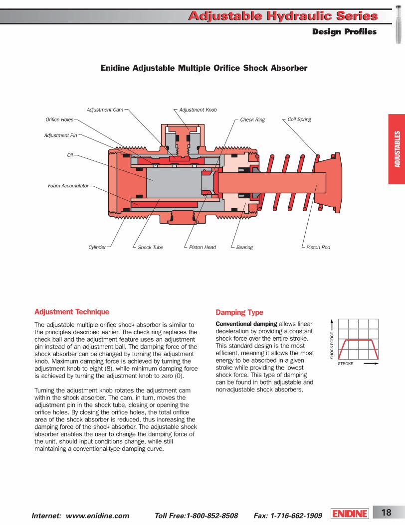
The adjustable multiple orifice shock absorber is similar tothe principles described earlier. The check ring replaces thecheck ball and the adjustment feature uses an adjustmentpin instead of an adjustment ball. The damping force of theshock absorber can be changed by turning the adjustmentknob. Maximum damping force is achieved by turning theadjustment knob to eight (8), while minimum damping forceis achieved by turning the adjustment knob to zero (0).
Turning the adjustment knob rotates the adjustment camwithin the shock absorber. The cam, in turn, moves theadjustment pin in the shock tube, closing or opening the orifice holes. By closing the orifice holes, the total orificearea of the shock absorber is reduced, thus increasing thedamping force of the shock absorber. The adjustable shockabsorber enables the user to change the damping force ofthe unit, should input conditions change, while still maintaining a conventional-type damping curve.
Adjustment Knob
Coil Spring
Shock Tube Piston Head Piston Rod
Check RingOrifice Holes
Cylinder
Oil
Foam Accumulator
Adjustment Cam
Bearing
Adjustment Pin
Adjustable Hydraulic SeriesAdjustable Hydraulic SeriesDesign Profiles
Enidine Adjustable Multiple Orifice Shock Absorber
Damping TypeConventional damping allows linear deceleration by providing a constant shock force over the entire stroke. This standard design is the most efficient, meaning it allows the most energy to be absorbed in a given stroke while providing the lowest shock force. This type of damping can be found in both adjustable and non-adjustable shock absorbers.
ShockCover5-2B 3/31/03 2:29 PM Page 18

Catalog No.(Model)
All dimensions in inches.
Notes: 1. All shock absorbers will function satisfactorily at 5% of their maximum rated energy per cycle. If less than 5%, a smaller model should be specified.
2. For mounting accessories, see pages 22-30.3. (B) indicates button model of shock absorber. Buttons cannot be added to non-button models or removed from button models OEM .1M to OEM 1.0.4. Urethane striker caps are available as accessories for models OEM 1.15 x 1 to OEM 1.25 x 2.
Nominal Coil Spring Force
All dimensions in inches.
A A1 C D E E1 F G H J WF WLOEM .1M (B) 2.25 2.63 M10 x 1,0 .12 N/A 0.34 1.95 .34 .40 N/A N/A N/AOEM .15M (B) 3.22 3.61 M12 x 1,0 .13 N/A 0.34 2.81 .43 .56 N/A .43 .38(LR)OEM .25 (B) 3.22 3.59 1/2-20 UNF .13 N/A 0.44 2.81 .43 .56 N/A .44 .50(LR)OEM .35 (B) 3.96 4.36 9/16-18 UNF .16 N/A 0.44 3.44 .44 .57 .02 .50 .50(LR)OEM .5 (B) 3.88 4.35 3/4-16 UNF .19 N/A 0.50 3.31 .63 .67 N/A .68 .50(LR)OEM 1.0 (B) 5.12 5.62 1-12 UNF .25 N/A 0.62 4.09 .87 .55 .18 .88 .50(LR)OEM 1.15 x 1 5.92 6.12 11/4-12 UNF .38 1.13 1.20 3.81 1.10 .55 .21 1.12 .63(LR)OEM 1.15 x 2 8.54 8.74 11/4-12 UNF .38 1.13 1.20 5.43 1.10 .55 .21 1.12 .63(LR)OEM 1.25 x 1 5.92 6.12 13/8-12 UNF .38 1.13 1.20 3.81 1.10 .55 .21 1.25 .63(LR)OEM 1.25 x 2 8.54 8.74 13/8-12 UNF .38 1.13 1.20 5.43 1.10 .55 .21 1.25 .63
Optimal (FP) (FD)Bore (S) Velocity (ET) (ETC) Max. Max. Model
Catalog No. Size Stroke Range Max. Max. Shock Extended Compressed Propelling Weight(Model) (in.) (in.) (in./sec.) in.-lbs./cycle in.-lbs./hour Force (lbs.) (lbs.) (lbs.) Force (lbs.) (oz.)
OEM .1M (B) .24 0.28 12-130 50 110,000 275 0.5 1.0 80 1OEM .15M (B) .25 0.38 12-130 50 168,000 200 0.8 1.7 80 2OEM .25 (B) .25 0.38 12-130 50 178,000 200 0.8 1.7 80 2LROEM .25 (B) .25 0.38 3-50 50 178,000 200 0.8 1.7 100 2OEM .35 (B) .28 0.50 12-130 150 300,000 450 1.0 2.2 120 3LROEM .35 (B) .28 0.50 3-50 150 300,000 450 1.0 2.2 200 3OEM .5 (B) .44 0.50 12-180 250 284,000 775 1.3 2.8 150 5LROEM .5 (B) .44 0.50 3-50 250 284,000 775 2.0 3.8 250 5OEM 1.0 (B) .50 1.00 12-130 650 622,000 1,000 3.0 6.0 300 10LROEM 1.0 (B) .50 1.00 3-50 650 622,000 1,000 3.0 6.0 450 10OEM 1.15 x 1 .63 1.00 12-130 1,700 670,000 2,500 12.5 20.0 500 17LROEM 1.15 x 1 .63 1.00 3-80 1,700 670,000 2,500 12.5 20.0 750 17OEM 1.15 x 2 .63 2.00 12-130 3,400 875,000 2,500 7.0 20.0 500 25LROEM 1.15 x 2 .63 2.00 3-80 3,400 875,000 2,500 7.0 20.0 750 25OEM 1.25 x 1 .63 1.00 12-130 1,700 808,000 2,500 12.5 20.0 500 20LROEM 1.25 x 1 .63 1.00 3-80 1,700 808,000 2,500 12.5 20.0 750 20OEM 1.25 x 2 .63 2.00 12-130 3,400 986,000 2,500 7.0 20.0 500 26LROEM 1.25 x 2 .63 2.00 3-80 3,400 986,000 2,500 7.0 20.0 750 26
Adjustable Hydraulic SeriesAdjustable Hydraulic Series
Internet: www.enidine.com Toll Free: 1-800-852-8508 Fax: 1-716-662-190919
AD
JUSTA
BLE
S
ØD
ØE1*ØEØG
A1*
C
F
H
A
WF WLAdjustment
Knob
Urethane Cap(Optional)
ØD
ØE1*ØG
H
A1*
C J
J
FA
OEM 0.1M ➞ OEM 1.0
WF WL
Adjustment Knob
*Note: A1 and E1 apply to button models and urethane striker cap accessory.
OEM 1.15 ➞ OEM 1.25
OEM Platinum Series
23
ShockCover5-2B 3/31/03 2:29 PM Page 19

Adjustable Hydraulic SeriesAdjustable Hydraulic Series
20Internet: www.enidine.com Toll Free:1-800-852-8508 Fax: 1-716-662-1909
OEM 3/4 ➞ OEM 1 1/8
AD
JUSTA
BLE
S
Optimal (FP) (FD)Bore (S) Velocity (ET ) (ETC) Max. Max. Model
Catalog No. Size Stroke Range Max. Max. Shock Extended Compressed Propelling Weight(Model) (in.) (in.) (in./sec.) in.-lbs./cycle in.-lbs./hour Force (lbs.) (lbs.) (lbs.) Force (lbs.) (lbs.)
OEM 3⁄4 x 1 0.75 1 12-140 2,300 1,120,000 3,000 11 15 650 2.6LROEM 3⁄4 x 1 0.75 1 3-55 2,300 1,120,000 3,000 11 15 1,500 2.6OEM 3⁄4 x 2 0.75 2 12-140 4,600 1,475,000 3,000 7 15 650 2.9LROEM 3⁄4 x 2 0.75 2 3-55 4,600 1,475,000 3,000 11 18 1,500 2.9OEM 3⁄4 x 3 0.75 3 12-140 6,900 1,775,000 3,000 7 18 650 3.4LROEM 11⁄8 x 1 1.13 1 3-30 6,000 2,000,000 7,800 26 35 4,000 6.5OEM 11⁄8 x 2 1.13 2 12-140 12,000 2,400,000 7,800 17 35 1,500 9.9LROEM 11⁄8 x 2 1.13 2 3-30 12,000 2,400,000 7,800 17 35 4,000 9.9OEM 11⁄8 x 4 1.13 4 12-140 24,000 3,200,000 7,800 16 36 1,500 11.6OEM 11⁄8 x 6 1.13 6 12-140 36,000 3,730,000 7,800 20 64 1,500 14.5
All dimensions in inches.
Catalog No.(Model)
Nominal Coil Spring Force
Notes: 1. All shock absorbers will function satisfactorily at 5% of their maximum rated energy per cycle. If less than 5%, a smaller model should be specified.
2. Air/Oil (AOEM, LRAOEM) models – max. in-lbs per hour is 20% higher than the standard OEM/LROEM models.3. For mounting accessories, see pages 22-30.4. Rear flange mounting not recommended for OEM 1 1/8 x 6 when mounting horizontally.
ØD
ØE1*
Adjustment Knob WL
K1K
CØB
WF
All dimensions in inches.
F
ØE
A
A1*
*Note: A1 and E1 apply to urethane striker cap accessory.
A A1 B C D E E1 F K K1 WF WL
(LR)OEM 3⁄4 x 1 5.68 6.38 2.25 13/4-12 UN .50 1.50 1.75 3.63 0.91 0.82 2.00 0.42(LR)OEM 3⁄4 x 2 7.68 8.38 2.25 13/4-12 UN .50 1.50 1.75 4.63 0.91 0.82 2.00 0.50OEM 3⁄4 x 3 9.68 10.38 2.25 13/4-12 UN .50 1.50 1.75 5.63 0.91 0.82 2.00 0.50LROEM 11⁄8 x 1 6.90 7.59 3.00 2 1/2-12 UN .75 2.00 2.25 4.50 1.03 1.03 2.75 0.50(LR)OEM 11⁄8 x 2 8.90 9.59 3.00 2 1/2-12 UN .75 2.00 2.25 5.50 1.03 1.03 2.75 1.00OEM 11⁄8 x 4 12.90 13.59 3.00 2 1/2-12 UN .75 2.00 2.25 7.50 1.03 1.03 2.75 1.00OEM 11⁄8 x 6 17.97 18.66 3.00 2 1/2-12 UN .75 2.38 2.38 9.50 1.03 1.03 2.75 1.00
OEM Low Profile Series
23
ShockCover5-2B 3/31/03 2:29 PM Page 20

Internet: www.enidine.com Toll Free: 1-800-852-8508 Fax: 1-716-662-190921
AD
JUSTA
BLE
S
OEM Large Series
A A1 B C D E E1 F H J K(LR)OEM 1.5M x 1 5.68 6.38 2.00 M42 x 1.5 0.50 1.50 1.75 3.63 1.82 1.44 1.26(LR)OEM 1.5M x 2 7.68 8.38 2.00 M42 x 1.5 0.50 1.50 1.75 4.63 2.32 1.44 1.76OEM 1.5M x 3 9.68 10.38 2.00 M42 x 1.5 0.50 1.50 1.75 5.63 2.82 1.44 2.26(LR)OEM 2.0M x 2 8.90 9.55 2.88 M64 x 2 0.75 2.00 2.25 5.50 2.75 1.89 2.00OEM 2.0M x 4 12.90 13.55 2.88 M64 x 2 0.75 2.00 2.25 7.50 3.75 1.89 3.00OEM 2.0M x 6 17.97 18.62 2.88 M64 x 2 0.75 2.38 2.38 9.50 4.75 1.89 3.00OEM 3.0M x 2 9.66 10.43 3.88 M85 x 2 0.88 2.75 3.00 5.53 2.77 2.25 2.02OEM 3.0M x 3.5 12.72 13.49 3.88 M85 x 2 0.88 2.75 3.00 7.06 3.53 2.25 2.78OEM 3.0M x 5 15.72 16.49 3.88 M85 x 2 0.88 2.75 3.00 8.50 4.28 2.25 2.78OEM 3.0M x 6.5 19.46 20.23 3.88 M85 x 2 0.88 3.19 3.19 10.06 5.03 2.25 2.78OEM 4.0M x 2 12.32 13.20 5.00 M115 x 2 1.38 3.50 3.75 8.00 4.00 2.89 3.13OEM 4.0M x 4 16.32 17.20 5.00 M115 x 2 1.38 3.50 3.75 10.00 5.00 2.89 4.13OEM 4.0M x 6 20.32 21.20 5.00 M115 x 2 1.38 3.50 3.75 12.00 6.00 2.89 4.25OEM 4.0M x 8 25.32 26.20 5.00 M115 x 2 1.38 3.50 3.75 14.00 7.00 2.89 4.25OEM 4.0M x 10 29.32 30.20 5.00 M115 x 2 1.38 3.50 3.75 16.00 8.00 2.89 4.25
All dimensions in inches.
Catalog No.(Model)
Notes: 1. All shock absorbers will function satisfactorily at 5% of their maximum rated energy per cycle. If less than 5%, a smaller model should be specified.
2. Air/Oil (AOEM, LRAOEM) models – max. in-lbs per hour is 20% higher than the standard OEM/LROEM models (see page 14).3. For mounting accessories, see pages 22-30.4. Rear flange mounting of OEM 2.0M x 6, OEM 3.0M x 6.5, OEM 4.0M x 8 and OEM 4.0M x 10 models not recommended when mounting horizontally.
Nominal Coil Spring Force
All dimensions in inches.
ØD
C
HF
ØE1*
ØB
J
KTYP
Adjustment Knob
A1*
*Note: A1 and E1 apply to urethane striker cap accessory.
A
ØE
OEM 1.5M ➞ OEM 4.0M
Adjustable Hydraulic SeriesAdjustable Hydraulic Series
Optimal (FP) (FD)Bore (S) Velocity (ET) (ETC) Max. Max. Model
Catalog No. Size Stroke Range Max. Max. Shock Extended Compressed Propelling Weight(Model) (in.) (in.) (in./sec.) in.-lbs./cycle in.-lbs./hour Force (lbs.) (lbs.) (lbs.) Force (lbs.) (lbs.)
OEM 1.5M x 1 0.75 1.0 12-140 2,300 1,120,000 3,000 11 15 650 2.0LROEM 1.5M x 1 0.75 1.0 3-55 2,300 1,120,000 3,000 11 15 1,500 2.0OEM 1.5M x 2 0.75 2.0 12-140 4,600 1,475,000 3,000 7 15 650 2.2LROEM 1.5M x 2 0.75 2.0 3-55 4,600 1,475,000 3,000 11 18 1,500 2.2OEM 1.5M x 3 0.75 3.0 12-140 6,900 1,775,000 3,000 7 18 650 2.6OEM 2.0M x 2 1.13 2.0 12-140 12,000 2,400,000 7,800 17 35 1,500 7.5LROEM 2.0M x 2 1.13 2.0 3-30 12,000 2,400,000 7,800 17 35 4,000 7.5OEM 2.0M x 4 1.13 4.0 12-140 24,000 3,200,000 7,800 16 36 1,500 8.8OEM 2.0M x 6 1.13 6.0 12-140 36,000 3,730,000 7,800 20 64 1,500 11.0OEM 3.0M x 2 1.50 2.0 12-170 20,000 3,290,000 15,000 25 45 2,700 15.5OEM 3.0M x 3.5 1.50 3.5 12-170 35,000 5,770,000 15,000 25 45 2,700 20.0OEM 3.0M x 5 1.50 5.0 12-170 50,000 8,260,000 15,000 16 45 2,700 24.0OEM 3.0M x 6.5 1.50 6.5 12-170 65,000 10,750,000 15,000 27 75 2,700 30.0OEM 4.0M x 2 2.00 2.0 12-170 34,000 13,300,000 25,000 50 65 4,800 33.0OEM 4.0M x 4 2.00 4.0 12-170 68,000 16,000,000 25,000 35 65 4,800 40.0OEM 4.0M x 6 2.00 6.0 12-170 102,000 18,600,000 25,000 30 70 4,800 44.0OEM 4.0M x 8 2.00 8.0 12-170 136,000 21,300,000 25,000 40 80 4,800 66.0OEM 4.0M x 10 2.00 10.0 12-170 170,000 24,000,000 25,000 30 80 4,800 73.0
23
ShockCover5-2B 3/31/03 2:29 PM Page 21
22Internet: www.enidine.com Toll Free:1-800-852-8508 Fax: 1-716-662-1909
AD
JUSTA
BLE
S
Clevis Mounting
Adjustable Hydraulic SeriesAdjustable Hydraulic Series
OEM 1.0
ØS
PW
ØM
L
X
ØN
V
ØQLock RingØN
ØT
CR
ØSP
WV
All dimensions in inches.
L
ØM
ØN
XW
ØM
V
OEM 3/4 ➙ OEM 4.0M
R
Q
CR
U
ØS
P
ØU
L
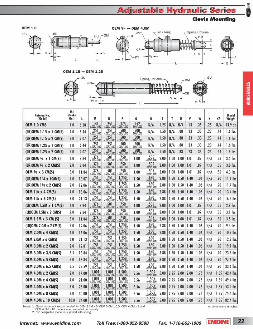
Notes: 1. Clevis mount not recommended for OEM 2.0M x 6, OEM 3.0M x 6.5, OEM 4.0M x 8 and OEM 4.0M x 10 models when mounted horizontally.
2. “S” designates model is supplied with spring.
Spring Optional
Spring Optional
(S)Stroke(in.)
Q
OEM 1.15 ➙ OEM 1.25
Catalog No. Model(Model) L M N P Q R S T U V W X CR Weight
OEM 1.0 CMS 1.0 6.38 .141 .251 .375 .252 N/A 1.25 N/A N/A .13 .35 .25 N/A 13.9 oz.+.005/-.000 +.005/-.000 +.000/-.010 +.000/-.003
(LR)OEM 1.15 x 1 CM(S) 1.0 6.44 .251 .251 .500 .500 N/A 1.50 N/A .88 .23 .33 .23 .44 1.6 lbs.+.005/-.000 +.005/-.000 +.000/-.010 +.000/-.010
(LR)OEM 1.15 x 2 CM(S) 2.0 9.07 .251 .251 .500 .500 N/A 1.50 N/A .88 .23 .33 .23 .44 1.6 lbs.+.005/-.000 +.005/-.000 +.000/-.010 +.000/-.010
(LR)OEM 1.25 x 1 CM(S) 1.0 6.44 .251 .251 .500 .500 N/A 1.50 N/A .88 .23 .33 .23 .44 1.6 lbs.+.005/-.000 +.005/-.000 +.000/-.010 +.000/-.010
(LR)OEM 1.25 x 2 CM(S) 2.0 9.07 .251 .251 .500 .500 N/A 1.50 N/A .88 .23 .33 .23 .44 1.9 lbs.+.005/-.000 +.005/-.000 +.000/-.010 +.000/-.010
(LR)OEM 3⁄4 x 1 CM(S) 1.0 7.84 .376 .501 .750 1.00 .505 2.00 1.00 1.00 1.01 .87 N/A .56 3.5 lbs.+.010/-.000 +.010/-.000 +.000/-.010 +.020/-.000
(LR)OEM 3⁄4 x 2 CM(S) 2.0 9.84 .376 .501 .750 1.00 .505 2.00 1.00 1.00 1.01 .87 N/A .56 3.8 lbs.+.010/-.000 +.010/-.000 +.000/-.010 +.020/-.000
OEM 3⁄4 x 3 CM(S) 3.0 11.84 .376 .501 .750 1.00 .505 2.00 1.00 1.00 1.01 .87 N/A .56 4.3 lbs.+.010/-.000 +.010/-.000 +.000/-.010 +.020/-.000
(LR)OEM 11⁄8 x 1CM(S) 1.0 10.07 .751 .751 1.250 1.50 .630 2.88 1.50 1.50 1.40 1.06 N/A .90 11.7 lbs.+.010/-.000 +.010/-.000 +.000/-.010 +.020/-.000
(LR)OEM 11⁄8 x 2 CM(S) 2.0 12.06 .751 .751 1.250 1.50 .630 2.88 1.50 1.50 1.40 1.06 N/A .90 11.7 lbs.+.010/-.000 +.010/-.000 +.000/-.010 +.020/-.000
OEM 11⁄8 x 4 CM(S) 4.0 16.06 .751 .751 1.250 1.50 .630 2.88 1.50 1.50 1.40 1.06 N/A .90 13.4 lbs.+.010/-.000 +.010/-.000 +.000/-.010 +.020/-.000
OEM 11⁄8 x 6 CM(S) 6.0 21.13 .751 .751 1.250 1.50 .630 2.88 1.50 1.50 1.40 1.06 N/A .90 16.3 lbs.+.010/-.000 +.010/-.000 +.000/-.010 +.020/-.000
(LR)OEM 1.5M x 1 CM(S) 1.0 7.84 .376 .501 .750 1.00 .505 2.00 1.00 1.00 1.01 .87 N/A .56 2.9 lbs.+.010/-.000 +.010/-.000 +.000/-.010 +.020/-.000
(LR)OEM 1.5M x 2 CM(S) 2.0 9.84 .376 .501 .750 1.00 .505 2.00 1.00 1.00 1.01 .87 N/A .56 3.1 lbs.+.010/-.000 +.010/-.000 +.000/-.010 +.020/-.000
OEM 1.5M x 3 CM (S) 3.0 11.84 .376 .501 .750 1.00 .505 2.00 1.00 1.00 1.01 .87 N/A .56 3.5 lbs.+.010/-.000 +.010/-.000 +.000/-.010 +.020/-.000
(LR)OEM 2.0M x 2 CM(S) 2.0 12.06 .751 .751 1.250 1.50 .630 2.88 1.50 1.50 1.40 1.06 N/A .90 9.4 lbs.+.010/-.000 +.010/-.000 +.000/-.010 +.020/-.000
OEM 2.0M x 4 CM(S) 4.0 16.06 .751 .751 1.250 1.50 .630 2.88 1.50 1.50 1.40 1.06 N/A .90 10.7 lbs.+.010/-.000 +.010/-.000 +.000/-.010 +.020/-.000
OEM 2.0M x 6 CM(S) 6.0 21.13 .751 .751 1.250 1.50 .630 2.88 1.50 1.50 1.40 1.06 N/A .90 12.9 lbs.+.010/-.000 +.010/-.000 +.000/-.010 +.020/-.000
OEM 3.0M x 2 CM(S) 2.0 12.81 .751 .751 1.250 1.50 .630 3.88 1.50 1.50 1.40 1.06 N/A .90 19.1 lbs.+.010/-.000 +.010/-.000 +.000/-.010 +.020/-.000
OEM 3.0M x 3.5 CM(S) 3.5 15.84 .751 .751 1.250 1.50 .630 3.88 1.50 1.50 1.40 1.06 N/A .90 23.6 lbs.+.010/-.000 +.010/-.000 +.000/-.010 +.020/-.000
OEM 3.0M x 5 CM(S) 5.0 18.84 .751 .751 1.250 1.50 .630 3.88 1.50 1.50 1.40 1.06 N/A .90 27.6 lbs.+.010/-.000 +.010/-.000 +.000/-.010 +.020/-.000
OEM 3.0M x 6.5 CM(S) 6.5 22.59 .751 .751 1.250 1.50 .630 3.88 1.50 1.50 1.40 1.06 N/A .90 33.6 lbs.+.010/-.000 +.010/-.000 +.000/-.010 +.020/-.000
OEM 4.0M x 2 CM(S) 2.0 17.00 1.001 1.001 1.500 3.56 1.505 5.00 2.25 2.00 2.00 1.75 N/A 1.35 42.4 lbs.+.010/-.000 +.010/-.000 +.000/-.010 +.020/-.000
OEM 4.0M x 4 CM(S) 4.0 21.00 1.001 1.001 1.500 3.56 1.505 5.00 2.25 2.00 2.00 1.75 N/A 1.35 49.4 lbs.+.010/-.000 +.010/-.000 +.000/-.010 +.020/-.000
OEM 4.0M x 6 CM(S) 6.0 25.00 1.001 1.001 1.500 3.56 1.505 5.00 2.25 2.00 2.00 1.75 N/A 1.35 53.4 lbs..010/-.000 +.010/-.000 +.000/-.010 +.020/-.000
OEM 4.0M x 8 CM(S) 8.0 30.00 1.001 1.001 1.500 3.56 1.505 5.00 2.25 2.00 2.00 1.75 N/A 1.35 75.4 lbs.+.010/-.000 +.010/-.000 +.000/-.010 +.020/-.000
OEM 4.0M x 10 CM(S) 10.0 34.00 1.001 1.001 1.500 3.56 1.505 5.00 2.25 2.00 2.00 1.75 N/A 1.35 82.4 lbs.+.010/-.000 +.010/-.000 +.000/-.010 +.020/-.000
ShockCover5-2B 3/31/03 2:29 PM Page 22
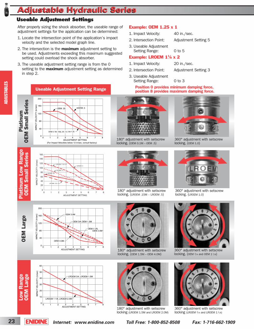
Internet: www.enidine.com Toll Free: 1-800-852-8508 Fax: 1-716-662-190923
AD
JUSTA
BLE
S
After properly sizing the shock absorber, the useable range ofadjustment settings for the application can be determined:
1. Locate the intersection point of the application’s impact velocity and the selected model graph line.
2. The intersection is the maximum adjustment setting to be used. Adjustments exceeding this maximum suggestedsetting could overload the shock absorber.
3. The useable adjustment setting range is from the 0 setting to the maximum adjustment setting as determinedin step 2.
Example: OEM 1.25 x 1
1. Impact Velocity: 40 in./sec.
2. Intersection Point: Adjustment Setting 5
3. Useable Adjustment Setting Range: 0 to 5
Example: LROEM 11⁄8 x 2
1. Impact Velocity: 20 in./sec.
2. Intersection Point: Adjustment Setting 3
3. Useable Adjustment Setting Range: 0 to 3
Pla
tinu
mO
EM S
mal
l Ser
ies
Low
Ran
ge
OEM
Lar
geO
EM L
arge
Position 0 provides minimum damping force, position 8 provides maximum damping force.
180° adjustment with setscrewlocking. (OEM 0.1M – OEM .5)
360° adjustment with setscrewlocking. (OEM 3/4 and OEM 11/8)
Useable Adjustment Setting Range
360° adjustment with setscrewlocking. (OEM 1.0)
180° adjustment with setscrewlocking (LROEM 1.5M and LROEM 2.0M)
360° adjustment with setscrewlocking (LROEM 3/4 and LROEM 11/8)
Pla
tinu
m L
ow R
ange
O
EM S
mal
l Ser
ies
180° adjustment with setscrewlocking. (OEM 1.5M – OEM 4.0M)
180° adjustment with setscrewlocking. (LROEM .15M – LROEM .5)
360° adjustment with setscrewlocking. (LROEM 1.0)
Useable Adjustment Settings
Adjustable Hydraulic SeriesAdjustable Hydraulic Series
ShockCover5-2B 3/31/03 2:29 PM Page 23

24Internet: www.enidine.com Toll Free:1-800-852-8508 Fax: 1-716-662-1909
AD
JUSTA
BLE
S
HP Series
Adjustable Hydraulic SeriesAdjustable Hydraulic Series
Optimal (FP) (FD)Bore (S) Velocity (ET) (ETC) Max. Max. ModelSize Stroke Range Max. Max. Shock Extended Compressed Propelling Weight(in.) (in.) (in./sec.) in.-lbs./cycle in.-lbs./hour Force (lbs.) (lbs.) (lbs.) Force (lbs.) (oz.)
HP 110 IF-1 .56 1.56 57-240 1,700 670,000 1,700 4 11 500 16HP 110 IF-2 .56 1.56 32-180 1,700 670,000 1,700 4 11 500 16HP 110 IF-3 .56 1.56 10-120 1,700 670,000 1,700 4 11 500 16
Hex Jam Nuts
ØG
H
C ØD
ØE JA
JB
JH
A
F
Adjustment Knob
Hex Jam Nut
Catalog No.(Model)
Nominal Coil Spring Force
Catalog No.(Model)
All dimensions in inches.
All dimensions in inches.
25
A C D E F G H JA JB JH
HP 110 1F-1 8.5 1-12 UNF .31 .88 5.45 .88 .81 1.30 1.13 .19HP 110 1F-2 8.5 1-12 UNF .31 .88 5.45 .88 .81 1.30 1.13 .19HP 110 1F-3 8.5 1-12 UNF .31 .88 5.45 .88 .81 1.30 1.13 .19
ShockCover5-2B 3/31/03 2:29 PM Page 24
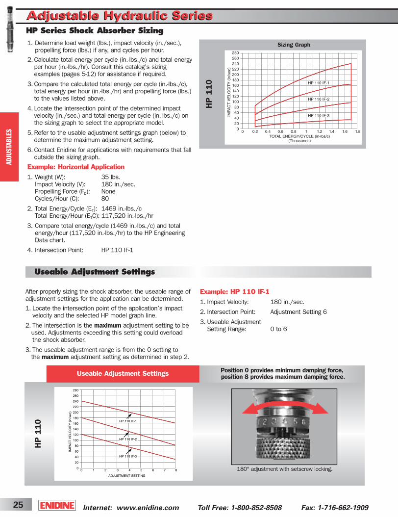
Adjustable Hydraulic SeriesAdjustable Hydraulic Series
Internet: www.enidine.com Toll Free: 1-800-852-8508 Fax: 1-716-662-190925
After properly sizing the shock absorber, the useable range ofadjustment settings for the application can be determined.
1. Locate the intersection point of the application’s impact velocity and the selected HP model graph line.
2. The intersection is the maximum adjustment setting to be used. Adjustments exceeding this setting could overload the shock absorber.
3. The useable adjustment range is from the 0 setting to the maximum adjustment setting as determined in step 2.
HP
110
Position 0 provides minimum damping force, position 8 provides maximum damping force.
180° adjustment with setscrew locking.
Useable Adjustment Settings
Example: HP 110 IF-1
1. Impact Velocity: 180 in./sec.
2. Intersection Point: Adjustment Setting 6
3. Useable Adjustment Setting Range: 0 to 6
AD
JUSTA
BLE
S
HP Series Shock Absorber Sizing
Useable Adjustment Settings
1. Determine load weight (lbs.), impact velocity (in./sec.), propelling force (lbs.) if any, and cycles per hour.
2. Calculate total energy per cycle (in.-lbs./c) and total energyper hour (in.-lbs./hr). Consult this catalog’s sizing examples (pages 5-12) for assistance if required.
3. Compare the calculated total energy per cycle (in.-lbs./c),total energy per hour (in.-lbs./hr) and propelling force (lbs.)to the values listed above.
4. Locate the intersection point of the determined impact velocity (in./sec.) and total energy per cycle (in.-lbs./c) on the sizing graph to select the appropriate model.
5. Refer to the usable adjustment settings graph (below) todetermine the maximum adjustment setting.
6. Contact Enidine for applications with requirements that falloutside the sizing graph.
Example: Horizontal Application
1. Weight (W): 35 lbs.Impact Velocity (V): 180 in./sec.Propelling Force (FD): NoneCycles/Hour (C): 80
2. Total Energy/Cycle (ET): 1469 in.-lbs./cTotal Energy/Hour (ETC): 117,520 in.-lbs./hr
3. Compare total energy/cycle (1469 in.-lbs./c) and total energy/hour (117,520 in.-lbs./hr) to the HP Engineering Data chart.
4. Intersection Point: HP 110 IF-1
Sizing Graph
HP
110
ShockCover5-2B 3/31/03 2:29 PM Page 25
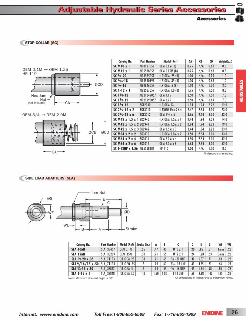
Adjustable Hydraulic Series AccessoriesAdjustable Hydraulic Series Accessories
26Internet: www.enidine.com Toll Free:1-800-852-8508 Fax: 1-716-662-1909
AD
JUSTA
BLE
S
Accessories
Catalog No. Part Number Model (Ref) Stroke (in.) A B C D E S WF WLSLA 10MF SLA_33457 OEM 0.1M .25 .47 .43 M10 x 1 .20 .85 .51 11mm .28SLA 12MF SLA_33299 OEM .15M .38 .71 .55 M12 x 1 .24 1.28 .63 13mm .28SLA 1⁄2-20 x .38 SLA_71133 (LR)OEM .25 .38 .71 .65 1⁄2 - 20 UNF .31 1.37 .71 .63 .28SLA 9/16/18 x .50 SLA_71134 (LR)OEM .35 .5 .79 .63 9⁄16 - 18 UNF .31 1.55 .71 .63 .28SLA 3⁄4-16 x .50 SLA_33847 (LR)OEM .5 .5 .94 .55 3⁄4 - 16 UNF .43 1.64 .98 .88 .28SLA 1-12 x 1 SLA_33848 (LR)OEM 1.0 1.0 1.50 1.80 1-12 UNF .59 2.88 1.42 1.25 .39
STOP COLLAR (SC)
SIDE LOAD ADAPTERS (SLA)
CA All dimensions in inches.
ØCDØCB
OEM 0.1M ➞ OEM 1.25HP 110
OEM 3/4 ➞ OEM 2.0M
Hex Jam Nut
(not included)
ØCD
CA
ØS
WF
E
Jam Nut
C
ØD
WLB A Stroke
All dimensions in inches unless otherwise noted.
Catalog No. Part Number Model (Ref) CA CB CD Weight(oz.)SC M10 x 1 M98921058 OEM 0.1M (B) 0.75 N/A 0.63 0.5SC M12 x 1 M95588058 OEM 0.15M (B) 0.75 N/A 0.63 0.5SC 1⁄2-20 M93935057 (LR)OEM .25 (B) 1.00 N/A 0.75 1.0SC 9⁄16-18 M94950199 (LR)OEM .35 (B) 1.00 N/A 0.69 1.0SC 3⁄4-16 M92646057 (LR)OEM .5 (B) 1.50 N/A 1.00 2.0SC 1-12 x 1 M92587057 (LR)OEM 1.0 (B) 1.75 N/A 1.50 8.0SC 11⁄4-12 M921049057 OEM 1.15 2.50 N/A 1.50 7.0SC 13⁄8-12 M921293057 OEM 1.25 2.50 N/A 1.69 7.0SC 13⁄4-12 8KE2940 (LR)OEM 3⁄4 1.94 1.94 2.22 12.0SC 21⁄2-12 x 2 8KE3010 (LR)OEM 11⁄8 x 2 & 4 2.47 2.54 3.00 23.0SC 21⁄2-12 x 6 8KE3012 OEM 11⁄8 x 6 3.66 2.54 3.00 33.0SC M42 x 1.5 x 1 8K2940 (LR)OEM 1.5M x 1 2.44 1.94 2.22 14.0SC M42 x 1.5 x 2 8K2941 (LR)OEM 1.5M x 2 2.94 1.94 2.22 19.0SC M42 x 1.5 x 3 8K2942 OEM 1.5M x 3 3.44 1.94 2.22 23.0SC M64 x 2 x 2 8K3010 (LR)OEM 2.0M x 2 3.50 2.54 3.00 33.0SC M64 x 2 x 4 8K3011 OEM 2.0M x 4 4.50 2.54 3.00 42.0SC M64 x 2 x 6 8K3012 OEM 2.0M x 6 5.63 2.54 3.00 52.0SC 1-12HP x 1.56 M95568181 HP 110 2.00 N/A 1.50 8.0
Note: Maximum sideload angle is 30°.
ShockCover5-2B 3/31/03 2:29 PM Page 26
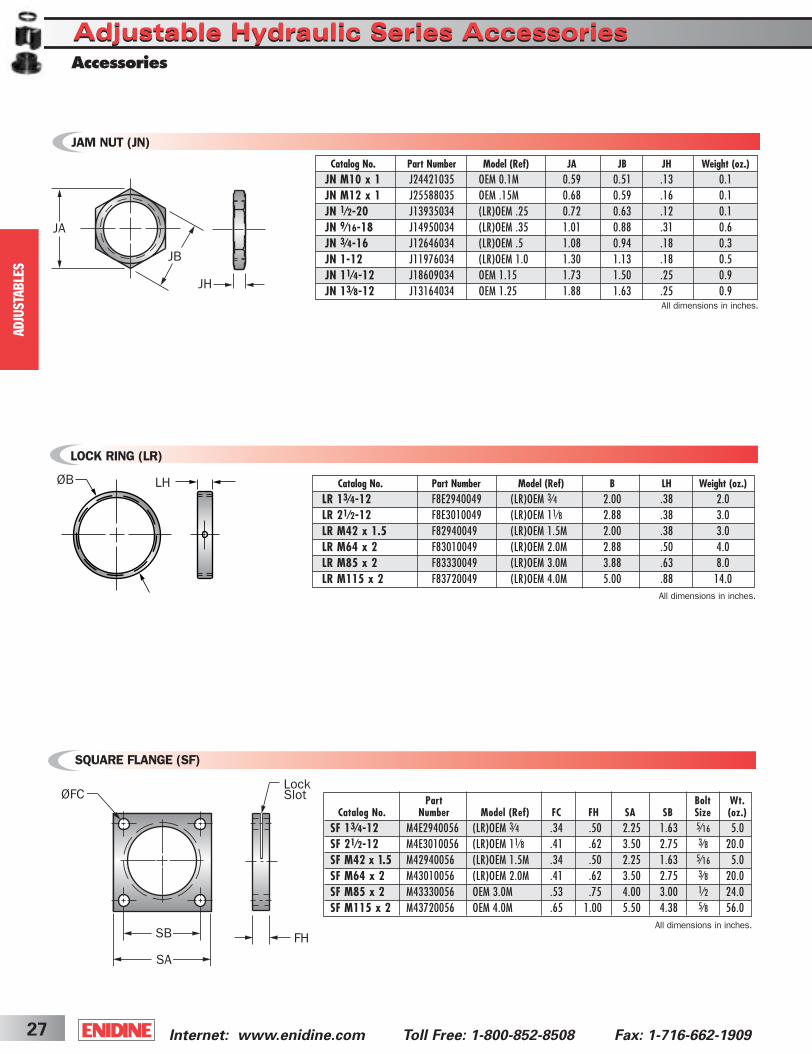
ØB LH
All dimensions in inches.
Internet: www.enidine.com Toll Free: 1-800-852-8508 Fax: 1-716-662-190927
Part Bolt Wt.Catalog No. Number Model (Ref) FC FH SA SB Size (oz.)
SF 13⁄4-12 M4E2940056 (LR)OEM 3⁄4 .34 .50 2.25 1.63 5⁄16 5.0SF 21⁄2-12 M4E3010056 (LR)OEM 11⁄8 .41 .62 3.50 2.75 3⁄8 20.0SF M42 x 1.5 M42940056 (LR)OEM 1.5M .34 .50 2.25 1.63 5⁄16 5.0SF M64 x 2 M43010056 (LR)OEM 2.0M .41 .62 3.50 2.75 3⁄8 20.0SF M85 x 2 M43330056 OEM 3.0M .53 .75 4.00 3.00 1⁄2 24.0SF M115 x 2 M43720056 OEM 4.0M .65 1.00 5.50 4.38 5⁄8 56.0
LOCK RING (LR)
SQUARE FLANGE (SF)
ØFC
SB
SA
FH
LockSlot
All dimensions in inches.
AD
JUSTA
BLE
S
Adjustable Hydraulic Series AccessoriesAdjustable Hydraulic Series AccessoriesAccessories
Catalog No. Part Number Model (Ref) B LH Weight (oz.)LR 13⁄4-12 F8E2940049 (LR)OEM 3⁄4 2.00 .38 2.0LR 21⁄2-12 F8E3010049 (LR)OEM 11⁄8 2.88 .38 3.0LR M42 x 1.5 F82940049 (LR)OEM 1.5M 2.00 .38 3.0LR M64 x 2 F83010049 (LR)OEM 2.0M 2.88 .50 4.0LR M85 x 2 F83330049 (LR)OEM 3.0M 3.88 .63 8.0LR M115 x 2 F83720049 (LR)OEM 4.0M 5.00 .88 14.0
JAM NUT (JN)
Catalog No. Part Number Model (Ref) JA JB JH Weight (oz.)JN M10 x 1 J24421035 OEM 0.1M 0.59 0.51 .13 0.1JN M12 x 1 J25588035 OEM .15M 0.68 0.59 .16 0.1JN 1⁄2-20 J13935034 (LR)OEM .25 0.72 0.63 .12 0.1JN 9⁄16-18 J14950034 (LR)OEM .35 1.01 0.88 .31 0.6JN 3⁄4-16 J12646034 (LR)OEM .5 1.08 0.94 .18 0.3JN 1-12 J11976034 (LR)OEM 1.0 1.30 1.13 .18 0.5JN 11⁄4-12 J18609034 OEM 1.15 1.73 1.50 .25 0.9JN 13⁄8-12 J13164034 OEM 1.25 1.88 1.63 .25 0.9
JA
JB
JH
All dimensions in inches.
ShockCover5-2B 3/31/03 2:29 PM Page 27

Model (Ref) A B C D E F T Bolt SizeT58706300 OEM 3/4 .63 1.03 2.25 1.63 .31 .32 5/16 - 24 UNF X 3/4 DEEP 5/16 6.1T58650300 OEM 11/8 .63 1.42 3.50 2.75 .38 .32 3/8 - 24 UNF X 3/4 DEEP 3/8 10.5
All dimensions in inches.Note: Kit includes 2 Stop Bars, Rectangular Flange, and Lock Ring.
Kit PartNumber
Wt.(oz.)
A B
C
E
D
F
2X T
STOP BAR KIT (SB)
URETHANE STRIKER CAP (UC)
RECTANGULAR FLANGE (RF)
RDRE
FH
LockSlot
SBSA
A
All dimensions in inches.
All dimensions in inches.
ØFC
Note: For complete shock absorber dimensionwith urethane striker cap, refer to engineering data, pages 19-21.
ØE1
Part Bolt Wt.Catalog No. Number Model (Ref) FC FH RD RE SA SB Size (oz.)
RF 11⁄4-12 N121049129 (LR)OEM 1.15 .22 .38 1.63 2.00 1.75 1.13 #10 1.0RF 13⁄8-12 N121293129 (LR)OEM 1.25 .22 .38 1.63 2.00 1.75 1.13 #10 1.0RF 13⁄4-12 M5E2940053 (LR)OEM 3⁄4 .34 .50 2.38 3.00 2.25 1.63 5⁄16 9.0RF M42 x 1.5 M52940053 (LR)OEM 1.5M .34 .50 2.38 3.00 2.25 1.63 5⁄16 9.0RF M85 x 2 M53330053 OEM 3.0M .53 .75 4.00 5.00 4.00 3.00 1⁄2 37.0
28Internet: www.enidine.com Toll Free:1-800-852-8508 Fax: 1-716-662-1909
AD
JUSTA
BLE
S
Adjustable Hydraulic Series AccessoriesAdjustable Hydraulic Series AccessoriesAccessories
Catalog No. Part Number Model (Ref) A E1 Wt. (oz.)UC 8609 C98609079 (LR)OEM 1.15/1.25 .39 1.20 0.2UC 2940 C92940079 (LR)OEM 3⁄4 .97 1.75 0.5UC 3010 C93010079 (LR)OEM 11⁄8 .95 2.25 0.8UC 2940 C92940079 (LR)OEM 1.5M .97 1.75 0.5UC 3010 C93010079 (LR)OEM 2.0M .95 2.25 0.8UC 3330 C93330079 OEM 3.0M 1.22 3.00 3.0UC 3720 C93720079 OEM 4.0M 1.47 3.75 6.0
ShockCover5-2B 3/31/03 2:29 PM Page 28
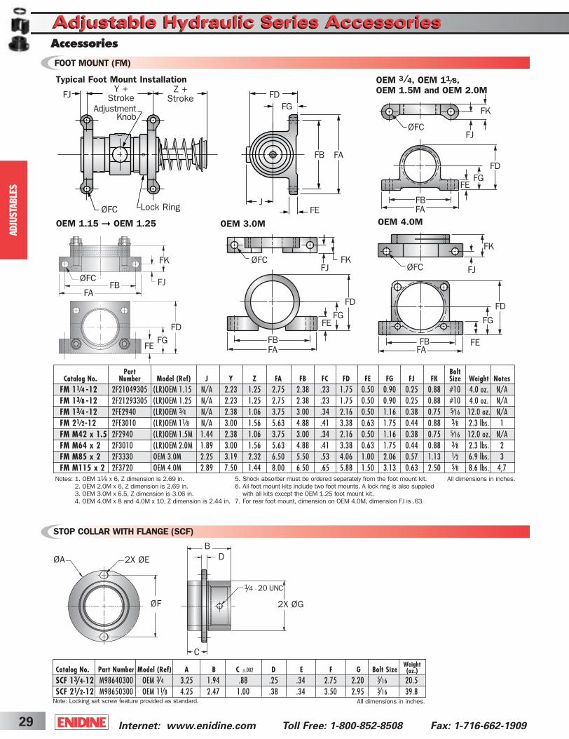
Adjustable Hydraulic Series AccessoriesAdjustable Hydraulic Series AccessoriesAccessories
2X ØE
2X ØGØF
ØA DB
C
1/4 - 20 UNC
Internet: www.enidine.com Toll Free: 1-800-852-8508 Fax: 1-716-662-190929
FOOT MOUNT (FM)
STOP COLLAR WITH FLANGE (SCF)
AD
JUSTA
BLE
S
OEM 3/4, OEM 11/8, OEM 1.5M and OEM 2.0M
FD
FGFE
FA
FB
FK
FJøFC
Notes: 1. OEM 11⁄8 x 6, Z dimension is 2.69 in.2. OEM 2.0M x 6, Z dimension is 2.69 in.3. OEM 3.0M x 6.5, Z dimension is 3.06 in.4. OEM 4.0M x 8 and 4.0M x 10, Z dimension is 2.44 in.
FD
FBFA
FK
FE
FJ
FG
FB
FE
FJ
FG
FA
FD
FJY +
Stroke
ØFC Lock Ring
Z +Stroke
AdjustmentKnob
FDFG
FAFB
JFE
FAFB
ØFC
FE
FJ
FD
FKFK
ØFC
FD
FG
FBFA
FE
All dimensions in inches.
OEM 3.0M OEM 4.0M
ØFC
FK
ØFC
FG
FJ
5. Shock absorber must be ordered separately from the foot mount kit.6. All foot mount kits include two foot mounts. A lock ring is also supplied
with all kits except the OEM 1.25 foot mount kit.7. For rear foot mount, dimension on OEM 4.0M, dimension FJ is .63.
Typical Foot Mount Installation
Catalog No. Part Number Model (Ref) A B C D E F G Bolt SizeSCF 13/4-12 M98640300 OEM 3/4 3.25 1.94 .88 .25 .34 2.75 2.20 5/16 20.5SCF 21/2-12 M98650300 OEM 11/8 4.25 2.47 1.00 .38 .34 3.50 2.95 5/16 39.8
All dimensions in inches.
Weight(oz.)±.002
Note: Locking set screw feature provided as standard.
OEM 1.15 ➞ OEM 1.25
Part BoltCatalog No. Number Model (Ref) J Y Z FA FB FC FD FE FG FJ FK Size Weight Notes
FM 11⁄4 -12 2F21049305 (LR)OEM 1.15 N/A 2.23 1.25 2.75 2.38 .23 1.75 0.50 0.90 0.25 0.88 #10 4.0 oz. N/AFM 13⁄8 -12 2F21293305 (LR)OEM 1.25 N/A 2.23 1.25 2.75 2.38 .23 1.75 0.50 0.90 0.25 0.88 #10 4.0 oz. N/AFM 13⁄4 -12 2FE2940 (LR)OEM 3⁄4 N/A 2.38 1.06 3.75 3.00 .34 2.16 0.50 1.16 0.38 0.75 5⁄16 12.0 oz. N/AFM 21⁄2-12 2FE3010 (LR)OEM 11⁄8 N/A 3.00 1.56 5.63 4.88 .41 3.38 0.63 1.75 0.44 0.88 3⁄8 2.3 lbs. 1FM M42 x 1.5 2F2940 (LR)OEM 1.5M 1.44 2.38 1.06 3.75 3.00 .34 2.16 0.50 1.16 0.38 0.75 5⁄16 12.0 oz. N/AFM M64 x 2 2F3010 (LR)OEM 2.0M 1.89 3.00 1.56 5.63 4.88 .41 3.38 0.63 1.75 0.44 0.88 3⁄8 2.3 lbs. 2FM M85 x 2 2F3330 OEM 3.0M 2.25 3.19 2.32 6.50 5.50 .53 4.06 1.00 2.06 0.57 1.13 1⁄2 6.9 lbs. 3FM M115 x 2 2F3720 OEM 4.0M 2.89 7.50 1.44 8.00 6.50 .65 5.88 1.50 3.13 0.63 2.50 5⁄8 8.6 lbs. 4,7
ShockCover5-2B 3/31/03 2:29 PM Page 29
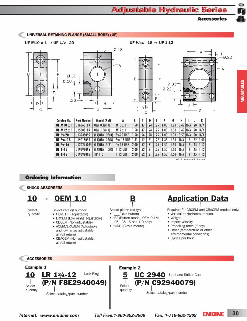
Accessories
Adjustable Hydraulic SeriesAdjustable Hydraulic Series
30Internet: www.enidine.com Toll Free:1-800-852-8508 Fax: 1-716-662-1909
Catalog No. Part Number Model (Ref) A B C D E F G H I J KUF M10 x 1 U16363189 OEM 0.1M(B) M10 x 1 1.50 .47 .24 .25 1.00 0.98 0.49 N/A .20 N/AUF M12 x 1 U15588189 OEM .15M(B) M12 x 1 1.50 .47 .24 .25 1.00 0.98 0.49 N/A .20 N/AUF 1⁄2-20 U13935095 (LR)OEM .25(B) 1⁄2-20 UNF 1.50 .56 .28 .25 1.00 1.00 0.50 N/A .20 N/AUF 9⁄16-18 U19018095 (LR)OEM .35(B) 9⁄16-18 UNF 1.81 .62 .31 .22 1.38 1.38 N/A .19 .32 1.00UF 3⁄4-16 U120275095 (LR)OEM .5(B) 3⁄4-16 UNF 2.00 .62 .31 .25 1.50 1.50 N/A .19 .45 1.12UF 1-12 U19599095 (LR)OEM 1.0(B) 1-12 UNF 2.00 .62 .31 .25 1.50 1.50 N/A .19 .45 1.12UF 1-12 U19599095 HP 110 1-12 UNF 2.00 .62 .31 .25 1.50 1.50 N/A .19 .45 1.12
UNIVERSAL RETAINING FLANGE (SMALL BORE) (UF)
Select piston rod type:• “___” (No button)• “B” (Button model, OEM 0.1M,
.25, .35, .5 and 1.0 only)• “CM” (Clevis mount)
SHOCK ABSORBERS
Ordering Information
ACCESSORIES
10 OEM 1.0- BSelect quantity
Example 1
10 LR 13/4-12 (P/N F8E2940049)
Select quantity
Select catalog/part number
Lock Ring
Example 2
5 UC 2940(P/N C92940079)Select
quantitySelect catalog/part number
Urethane Striker Cap
Select catalog number:• OEM, HP (Adjustable)• LROEM (Low range adjustable)• CBOEM (Non-adjustable)• AOEM/LRAOEM (Adjustable
and low range adjustable air/oil return)
• CBAOEM (Non-adjustable air/oil return)
Application DataRequired for CBOEM and CBAOEM models only:• Vertical or Horizontal motion• Weight• Impact velocity• Propelling force (if any)• Other (temperature or other
environmental conditions)• Cycles per hour
All dimensions in inches.
F
E
B
D
C
Ø.31Ø.18
.20
GH
A
Ø.18
F
E
B
DC
Ø.33Ø.22
JG
K
A
IØ.22
UF M10 x 1 ➞ UF 1/2 - 20 UF 9/16 - 18 ➞ UF 1-12
AD
JUSTA
BLE
S
ShockCover5-2B 3/31/03 2:29 PM Page 30
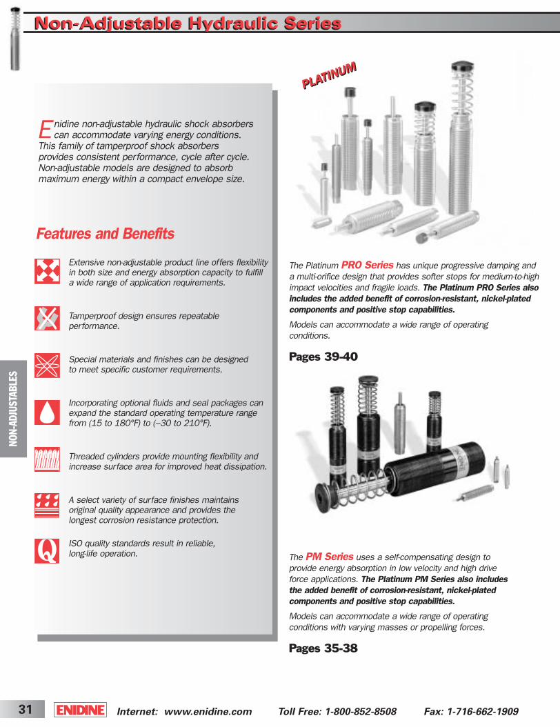
The Platinum PRO Series has unique progressive damping and a multi-orifice design that provides softer stops for medium-to-highimpact velocities and fragile loads. The Platinum PRO Series alsoincludes the added benefit of corrosion-resistant, nickel-plated components and positive stop capabilities.
Models can accommodate a wide range of operating conditions.
Pages 39-40
Internet: www.enidine.com Toll Free: 1-800-852-8508 Fax: 1-716-662-190931
NO
N-A
DJU
STA
BLE
S
Features and Benefits
Enidine non-adjustable hydraulic shock absorberscan accommodate varying energy conditions.
This family of tamperproof shock absorbers provides consistent performance, cycle after cycle.Non-adjustable models are designed to absorb maximum energy within a compact envelope size.
Extensive non-adjustable product line offers flexibilityin both size and energy absorption capacity to fulfilla wide range of application requirements.
Tamperproof design ensures repeatable performance.
Special materials and finishes can be designed to meet specific customer requirements.
Incorporating optional fluids and seal packages canexpand the standard operating temperature rangefrom (15 to 180°F) to (–30 to 210°F).
Threaded cylinders provide mounting flexibility andincrease surface area for improved heat dissipation.
A select variety of surface finishes maintains original quality appearance and provides the longest corrosion resistance protection.
ISO quality standards result in reliable, long-life operation. The PM Series uses a self-compensating design to
provide energy absorption in low velocity and high driveforce applications. The Platinum PM Series also includesthe added benefit of corrosion-resistant, nickel-plated components and positive stop capabilities.
Models can accommodate a wide range of operating conditions with varying masses or propelling forces.
Pages 35-38
Non-Adjustable Hydraulic SeriesNon-Adjustable Hydraulic Series
ShockCover5-2B 3/31/03 2:29 PM Page 31
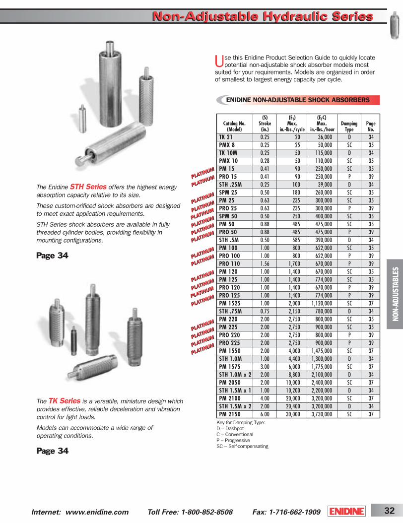
(S) (ET) (ETC)Catalog No. Stroke Max. Max. Damping Page
(Model) (in.) in.-lbs./cycle in.-lbs./hour Type No.TK 21 0.25 20 36,000 D 34PMX 8 0.25 25 50,000 SC 35TK 10M 0.25 50 115,000 D 34PMX 10 0.28 50 110,000 SC 35PM 15 0.41 90 250,000 SC 35PRO 15 0.41 90 250,000 P 39STH .25M 0.25 100 39,000 D 34SPM 25 0.50 180 260,000 SC 35PM 25 0.63 235 300,000 SC 35PRO 25 0.63 235 300,000 P 39SPM 50 0.50 250 400,000 SC 35PM 50 0.88 485 475,000 SC 35PRO 50 0.88 485 475,000 P 39STH .5M 0.50 585 390,000 D 34PM 100 1.00 800 622,000 SC 35PRO 100 1.00 800 622,000 P 39PRO 110 1.56 1,700 670,000 P 39PM 120 1.00 1,400 670,000 SC 35PM 125 1.00 1,400 774,000 SC 35PRO 120 1.00 1,400 670,000 P 39PRO 125 1.00 1,400 774,000 P 39PM 1525 1.00 2,000 1,120,000 SC 37STH .75M 0.75 2,150 780,000 D 34PM 220 2.00 2,750 800,000 SC 35PM 225 2.00 2,750 900,000 SC 35PRO 220 2.00 2,750 800,000 P 39PRO 225 2.00 2,750 900,000 P 39PM 1550 2.00 4,000 1,475,000 SC 37STH 1.0M 1.00 4,400 1,300,000 D 34PM 1575 3.00 6,000 1,775,000 SC 37STH 1.0M x 2 2.00 8,800 2,100,000 D 34PM 2050 2.00 10,000 2,400,000 SC 37STH 1.5M x 1 1.00 10,200 2,200,000 D 34PM 2100 4.00 20,000 3,200,000 SC 37STH 1.5M x 2 2.00 20,400 3,200,000 D 34PM 2150 6.00 30,000 3,730,000 SC 37
32Internet: www.enidine.com Toll Free: 1-800-852-8508 Fax: 1-716-662-1909
NO
N-A
DJU
STA
BLE
SThe TK Series is a versatile, miniature design whichprovides effective, reliable deceleration and vibration control for light loads.
Models can accommodate a wide range of operating conditions.
Page 34
The Enidine STH Series offers the highest energy absorption capacity relative to its size.
These custom-orificed shock absorbers are designedto meet exact application requirements.
STH Series shock absorbers are available in fully threaded cylinder bodies, providing flexibility in mounting configurations.
Page 34
Non-Adjustable Hydraulic SeriesNon-Adjustable Hydraulic Series
Use this Enidine Product Selection Guide to quickly locatepotential non-adjustable shock absorber models most
suited for your requirements. Models are organized in order of smallest to largest energy capacity per cycle.
Key for Damping Type:D – DashpotC – ConventionalP – ProgressiveSC – Self-compensating
ENIDINE NON-ADJUSTABLE SHOCK ABSORBERS
ShockCover5-2B 3/31/03 2:29 PM Page 32

NO
N-A
DJU
STA
BLE
S
Damping TypesConventional damping allows linear deceleration by providing a constant shock force over the entire stroke. This standard design is the most efficient, meaning it allows the most energy to be absorbed in a given stroke, while providing the lowest shock force. This type of damping is also available in adjustable shock absorbers.
Progressive damping provides deceleration with a gradually increasingshock force. The initial minimalresistance at impact protects delicateloads and machinery from damage.Progressive damping shock absorbersalso have built-in self-compensation, so they can operate over a wide range of weights and velocities. This type of damping provides smooth decelerationin applications where energy conditionsmay change.
Self-compensating dampingmaintains acceptable deceleration with conventional type damping characteristics. Self-compensating shock absorbers operate over a wide range of weights and velocities. Theseshock absorbers are well suited for highdrive force, low velocity applications, and where energy conditions may change. Curve A shows the shock force vs. strokecurve of a self-compensating shock absorber impacted with a low velocity and high drive force. Curve B shows the shock force vs. stroke curve of a self-compensating shock absorber impacted with a high velocity and low drive force.
Constant orifice area damping (Dashpot)provides the largest shock force at the beginning of the stroke when impact velocity is highest. These shock absorbers provide high-energy absorption in a small, economical design. This type of damping is also available in adjustable shock absorbers.
Non-Adjustable Multiple Orifice Shock AbsorberThe design of a multi-orifice shock absorber features a double cylinder arrangement with space between the concentric shock tube and cylinder, and a series of orificeholes drilled down the length of the shock tube wall.
During piston movement, the check ring is seated and oil is forced through the orifices in the shock tube wall, into the
closed cellular foam accumulator and behind the piston head.The orifice area decreases as the piston head moves andcloses the orifice holes. During repositioning, the coil springpushes the piston rod outward. This unseats the check ringand permits the oil to flow from the accumulator and acrossthe piston head, back into the shock tube.
Multiple orifice shock absorbers can provide conventional,progressive, self-compensating or constant orifice area (dashpot) damping.
Coil SpringShock TubePiston Head
Piston Rod Orifice Holes CylinderOilFoam Accumulator
Check RingBearing
Internet: www.enidine.com Toll Free: 1-800-852-8508 Fax: 1-716-662-190933
Non-Adjustable Hydraulic SeriesNon-Adjustable Hydraulic SeriesDesign Profiles
Enidine Non-Adjustable Multiple Orifice Shock Absorber
ShockCover5-2B 3/31/03 2:29 PM Page 33

(FP)Bore (S) (ET) (ETC) Max.
Catalog No. Size Stroke Max. Max. Shock Extended Compressed Model(Model) (in.) (in.) in.-lbs./cycle in.-lbs./hour Force (lbs.) (lbs.) (lbs.) Weight A A1 C D E F WF
STH .25M 0.44 0.25 100 39,000 615 2.5 4.0 2.8 oz. N/A 2.81 M14 X 1.0 .19 .50 2.00 .50STH .5M 0.57 0.50 585 390,000 1,800 4.0 7.0 7.7 oz. N/A 3.50 M22 X 1.5 .22 .38 2.70 .88STH .75M 0.77 0.75 2,180 780,000 4,400 8.0 20.0 1.1 lbs. N/A 5.13 M30 X 2.0 .31 .56 4.06 1.13STH 1.0M 1.00 1.00 4,400 1,300,000 6,700 22.0 53.0 1.6 lbs. N/A 6.70 M36 X 1.5 .38 .69 5.38 1.25STH 1.0M x 2 1.00 2.00 8,800 2,100,000 6,700 15.0 30.0 1.9 lbs. N/A 9.38 M36 X 1.5 .38 .69 7.02 1.25STH 1.5M x 1 1.38 1.00 10,200 2,200,000 14,600 20.0 51.0 3.1 lbs. 7.09 N/A M45 X 1.5 .63 N/A 6.06 1.63STH 1.5M x 2 1.38 2.00 20,400 3,200,000 14,600 12.5 51.0 4.0 lbs. 10.63 N/A M45 X 1.5 .63 N/A 8.62 1.63
WF CF
ØD
AA1
ØE1
STH .25M ➞ STH 1.5M x 2
All dimensions in inches.
Nominal Coil Spring Force
Notes: 1. Custom orificed application data needed.2. All shock absorbers will function at 5% of their rated energy per cycle. If less than 5%, a smaller model should be specified. 3. Enidine recommends a positive stop to prevent bottoming of the shock absorber.
TK 1
0M
0
-2-1
-3
-5
-7
-6
-8
-9
-4
TOTAL ENERGY (in-lbs/c)
IMPACT V
ELO
CIT
Y (
in/s
ec)
NO
N-A
DJU
STA
BLE
S
34Internet: www.enidine.com Toll Free: 1-800-852-8508 Fax: 1-716-662-1909
Non-Adjustable Hydraulic SeriesNon-Adjustable Hydraulic SeriesTK and STH Series
ØGQ
HF
A
C ØD
ØG
Q
H
FA
CØD
WF
WL
A1*
ØE*
TK 10M
All dimensions in inches.
Nominal Coil Spring Force
Note: 1. A positive stop is required to prevent the bottoming of the TK 21 shock absorber.
Catalog No.
(Model)
Catalog No.(Model)
TK 21
TK 2
1
TOTAL ENERGY (in-lbs/c)
IMPACT V
ELO
CIT
Y (
in/s
ec)
(FP) (FD)Bore (S) (ET) (ETC) Max. Max. Model
Damping Size Stroke Max. Max. Shock Extended Compressed Propelling WeightConstant (in.) (in.) in.-lbs./cycle in.-lbs./hour Force (lbs.) (lbs.) (lbs.) Force (lbs.) (oz.)
TK 21 -1, -2, -3 .28 .25 20 36,000 160 .65 1.13 20 .4 TK 10M (B) -1 to -9 .28 .25 50 115,000 315 0.3 2.2 N/A .5
*Note: A1 and E apply to button models and urethane striker cap accessory.
Stroke (S) StrokeA A1 C D ØE F G H Q WF WL (in.) Constant
TK 21 1.39 N/A 3/8-32 UNEF .12 N/A 1.13 .32 .17 .05 N/A N/A 0.25 -1, -2, -3TK 10M (B) 1.75 2.14 M10 x 1.0 .12 .35 1.50 .33 .20 .06 .35 .16 0.25 -1 to -9
ShockCover5-2B 3/31/03 2:29 PM Page 34
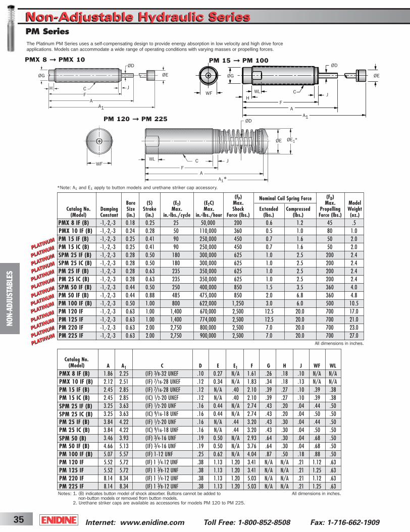
(FP) (FD)Bore (S) (ET) (ETC) Max. Max. Model
Catalog No. Damping Size Stroke Max. Max. Shock Extended Compressed Propelling Weight(Model) Constant (in.) (in.) in.-lbs./cycle in.-lbs./hour Force (lbs.) (lbs.) (lbs.) Force (lbs.) (oz.)
PMX 8 IF (B) -1,-2,-3 0.18 0.25 25 50,000 200 0.6 1.2 45 .5 PMX 10 IF (B) -1,-2,-3 0.24 0.28 50 110,000 360 0.5 1.0 80 1.0PM 15 IF (B) -1,-2,-3 0.25 0.41 90 250,000 450 0.7 1.6 50 2.0PM 15 IC (B) -1,-2,-3 0.25 0.41 90 250,000 450 0.7 1.6 50 2.0SPM 25 IF (B) -1,-2,-3 0.28 0.50 180 300,000 625 1.0 2.5 200 2.4SPM 25 IC (B) -1,-2,-3 0.28 0.50 180 300,000 625 1.0 2.5 200 2.4PM 25 IF (B) -1,-2,-3 0.28 0.63 235 350,000 625 1.0 2.5 200 2.4PM 25 IC (B) -1,-2,-3 0.28 0.63 235 350,000 625 1.0 2.5 200 2.4SPM 50 IF (B) -1,-2,-3 0.44 0.50 250 400,000 850 1.5 3.5 360 4.0PM 50 IF (B) -1,-2,-3 0.44 0.88 485 475,000 850 2.0 6.8 360 4.8PM 100 IF (B) -1,-2,-3 0.50 1.00 800 622,000 1,250 3.0 6.0 500 10.5PM 120 IF -1,-2,-3 0.63 1.00 1,400 670,000 2,500 12.5 20.0 700 17.0 PM 125 IF -1,-2,-3 0.63 1.00 1,400 774,000 2,500 12.5 20.0 700 21.0 PM 220 IF -1,-2,-3 0.63 2.00 2,750 800,000 2,500 7.0 20.0 700 23.0PM 225 IF -1,-2,-3 0.63 2.00 2,750 900,000 2,500 7.0 20.0 700 27.0
Internet: www.enidine.com Toll Free: 1-800-852-8508 Fax: 1-716-662-190935
NO
N-A
DJU
STA
BLE
S
All dimensions in inches.
All dimensions in inches.
Catalog No.(Model)
Notes: 1. (B) indicates button model of shock absorber. Buttons cannot be added to non-button models or removed from button models.
2. Urethane striker caps are available as accessories for models PM 120 to PM 225.
Nominal Coil Spring Force
PMX 8 ➞ PMX 10
*Note: A1 and E1 apply to button models and urethane striker cap accessory.
PM 120 ➞ PM 225
FA
A1*
ØD
CWF
WL
ØE1*ØE
ØEØG
FA
A1
ØD
CH
The Platinum PM Series uses a self-compensating design to provide energy absorption in low velocity and high drive force applications. Models can accommodate a wide range of operating conditions with varying masses or propelling forces.
PM 15 ➞ PM 100
ØEØG
F
J
J
J
AA1
ØD
CWFH
WL
PM SeriesNon-Adjustable Hydraulic SeriesNon-Adjustable Hydraulic Series
A A1 C D E E1 F G H J WF WLPMX 8 IF (B) 1.86 2.25 (IF) 3/8-32 UNEF .10 0.27 N/A 1.61 .26 .18 .10 N/A N/APMX 10 IF (B) 2.12 2.51 (IF) 7/16-28 UNEF .12 0.34 N/A 1.83 .34 .18 .13 N/A N/APM 15 IF (B) 2.45 2.85 (IF) 7/16-28 UNEF .12 N/A .40 2.10 .39 .27 .10 .39 .38PM 15 IC (B) 2.45 2.85 (IC) 1/2-20 UNEF .12 N/A .40 2.10 .39 .27 .10 .39 .38SPM 25 IF (B) 3.25 3.63 (IF) 1/2-20 UNF .16 0.44 N/A 2.74 .43 .20 .04 .44 .50SPM 25 IC (B) 3.25 3.63 (IC) 9/16-18 UNF .16 0.44 N/A 2.74 .43 .20 .04 .50 .50PM 25 IF (B) 3.84 4.22 (IF) 1/2-20 UNF .16 N/A .44 3.20 .43 .30 .04 .44 .50PM 25 IC (B) 3.84 4.22 (IC) 9/16-18 UNF .16 N/A .44 3.20 .43 .30 .04 .50 .50SPM 50 (B) 3.46 3.93 (IF) 3/4-16 UNF .19 0.50 N/A 2.93 .64 .30 .04 .68 .50PM 50 IF (B) 4.66 5.13 (IF) 3/4-16 UNF .19 0.50 N/A 3.76 .64 .30 .04 .68 .50PM 100 IF (B) 5.07 5.57 (IF) 1-12 UNF .25 0.62 N/A 4.04 .87 .50 .18 .88 .50PM 120 IF 5.52 5.72 (IF) 1 1/4-12 UNF .38 1.13 1.20 3.41 N/A N/A .21 1.12 .63PM 125 IF 5.52 5.72 (IF) 1 3/8-12 UNF .38 1.13 1.20 3.41 N/A N/A .21 1.25 .63PM 220 IF 8.14 8.34 (IF) 1 1/4-12 UNF .38 1.13 1.20 5.03 N/A N/A .21 1.12 .63PM 225 IF 8.14 8.34 (IF) 1 3/8-12 UNF .38 1.13 1.20 5.03 N/A N/A .21 1.25 .63
ShockCover5-2B 3/31/03 2:29 PM Page 35

PM
X 8
PM
X 1
0SP
M 2
5
PM
15
TOTAL ENERGY (in-lbs/c)
IMPACT V
ELO
CIT
Y (
in/s
ec)
TOTAL ENERGY (in-lbs/c)
IMPACT V
ELO
CIT
Y (
in/s
ec)
TOTAL ENERGY (in-lbs/c)
IMPACT V
ELO
CIT
Y (
in/s
ec)
TOTAL ENERGY (in-lbs/c)IM
PACT V
ELO
CIT
Y (
in/s
ec)
36Internet: www.enidine.com Toll Free:1-800-852-8508 Fax: 1-716-662-1909
NO
N-A
DJU
STA
BLE
S
PM Series
Non-Adjustable Hydraulic SeriesNon-Adjustable Hydraulic Series
0
10
20
30
40
50
60
70
80
90
100
110
120
130
140
150
0 10 20 30 40 50 60 70 80 90 100 110 120 130 140 150 160 170 180 190 200 210 220 230 240
0
25
50
75
100
125
150
0 20 40 60 80 100 120 140 160 180 200 220 240 260TOTAL ENERGY (in-lbs/c)
IMP
AC
T V
ELO
CIT
Y (
m/s
ec)
PM
25
SP
M 5
0
TOTAL ENERGY (in-lbs/c)
IMPACT V
ELO
CIT
Y (
in/s
ec)
TOTAL ENERGY (in-lbs/c)
IMPACT V
ELO
CIT
Y (
in/s
ec)
PM
50
PM
100
TOTAL ENERGY (in-lbs/c)
IMPACT V
ELO
CIT
Y (
in/s
ec)
TOTAL ENERGY (in-lbs/c)
IMPACT V
ELO
CIT
Y (
in/s
ec)
ShockCover5-2B 3/31/03 2:29 PM Page 36
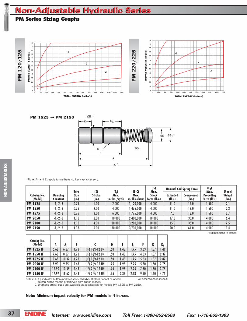
Internet: www.enidine.com Toll Free: 1-800-852-8508 Fax: 1-716-662-190937
Note: Minimum impact velocity for PM models is 4 in./sec.
NO
N-A
DJU
STA
BLE
S
PM Series Sizing GraphsNon-Adjustable Hydraulic SeriesNon-Adjustable Hydraulic Series
K
ØD
K1
ØE ØE1*
F
A
A1*
C
PM 1525 ➞ PM 2150 ØB
A A1 B C D E E1 F K K1
PM 1525 IF 5.68 6.37 1.73 (IF) 13/4-12 UN .50 1.48 1.75 3.63 1.37 1.49PM 1550 IF 7.68 8.37 1.73 (IF) 13/4-12 UN .50 1.48 1.75 4.63 1.37 2.37PM 1575 IF 9.68 10.37 1.73 (IF) 13/4-12 UN .50 1.48 1.75 5.63 1.37 2.87PM 2050 IF 8.90 9.55 2.48 (IF) 2 1/2-12 UN .75 1.98 2.25 5.50 1.50 2.75PM 2100 IF 12.90 13.55 2.48 (IF) 2 1/2-12 UN .75 1.98 2.25 7.50 1.50 3.75PM 2150 IF 17.97 18.62 2.48 (IF) 2 1/2-12 UN .75 2.38 2.38 9.50 1.50 4.75
All dimensions in inches.
All dimensions in inches.
Catalog No.(Model)
Notes: 1. (B) indicates button model of shock absorber. Buttons cannot be addedto non-button models or removed from button models.
2. Urethane striker caps are available as accessories for models PM 1525 to PM 2150.
*Note: A1 and E1 apply to urethane striker cap accessory.
Nominal Coil Spring Force
PM
220/225
PM
120/125
TOTAL ENERGY (in-lbs/c)
IMPACT V
ELO
CIT
Y (
in/s
ec)
TOTAL ENERGY (in-lbs/c)
IMPACT V
ELO
CIT
Y (
in/s
ec)
(FP) (FD)Bore (S) (ET) (ETC) Max. Max. Model
Catalog No. Damping Size Stroke Max. Max. Shock Extended Compressed Propelling Weight(Model) Constant (in.) (in.) in.-lbs./cycle in.-lbs./hour Force (lbs.) (lbs.) (lbs.) Force (lbs.) (lbs.)
PM 1525 -1,-2,-3 0.75 1.00 2,000 1,120,000 4,000 11.0 15.0 1,500 2.1 PM 1550 -1,-2,-3 0.75 2.00 4,000 1,475,000 4,000 11.0 18.0 1,500 2.3PM 1575 -1,-2,-3 0.75 3.00 6,000 1,775,000 4,000 7.0 18.0 1,500 2.7PM 2050 -1,-2,-3 1.13 2.00 10,000 2,400,000 10,000 17.0 35.0 4,000 6.4PM 2100 -1,-2,-3 1.13 4.00 20,000 3,200,000 10,000 15.5 36.0 4,000 7.5PM 2150 -1,-2,-3 1.13 6.00 30,000 3,730,000 10,000 20.0 64.0 4,000 9.4
ShockCover5-2B 3/31/03 2:29 PM Page 37
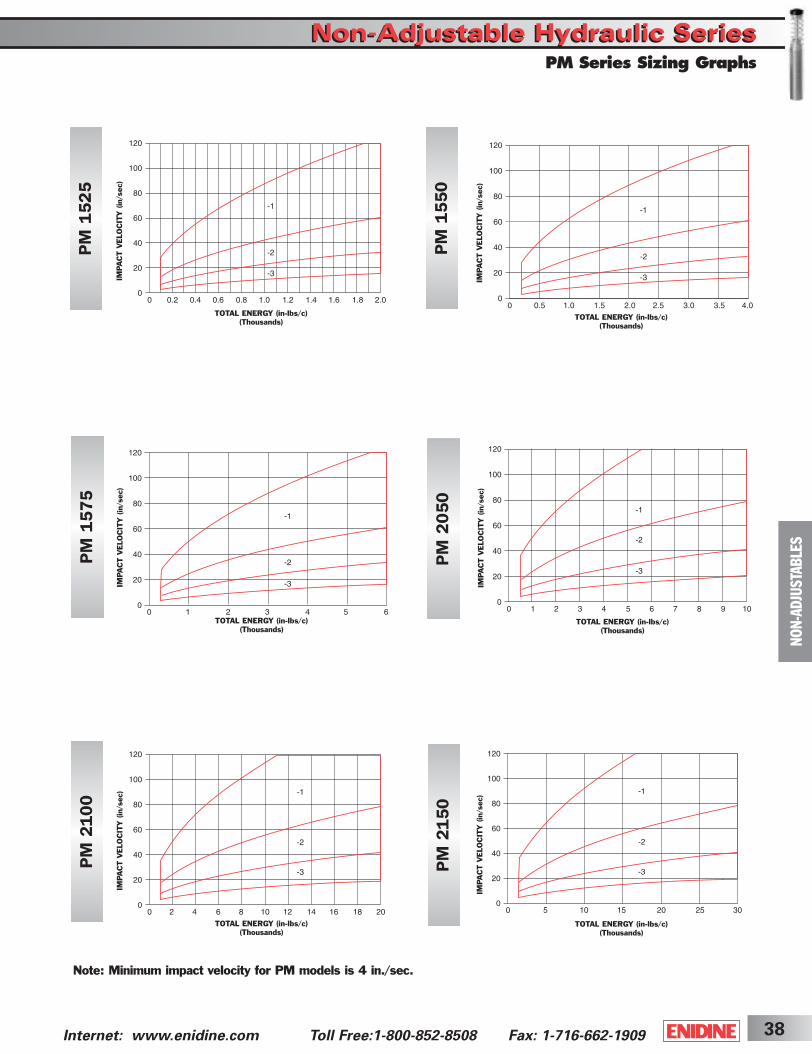
38Internet: www.enidine.com Toll Free:1-800-852-8508 Fax: 1-716-662-1909
PM
1525
PM
1550
PM
1575
PM
2050
PM
2100
PM
2150
Note: Minimum impact velocity for PM models is 4 in./sec.
NO
N-A
DJU
STA
BLE
S
PM Series Sizing Graphs
TOTAL ENERGY (in-lbs/c)(Thousands)
IMPACT V
ELO
CIT
Y (
in/s
ec)
TOTAL ENERGY (in-lbs/c)(Thousands)
IMPACT V
ELO
CIT
Y (
in/s
ec)
TOTAL ENERGY (in-lbs/c)(Thousands)
IMPACT V
ELO
CIT
Y (
in/s
ec)
TOTAL ENERGY (in-lbs/c)(Thousands)
IMPACT V
ELO
CIT
Y (
in/s
ec)
TOTAL ENERGY (in-lbs/c)(Thousands)
IMPACT V
ELO
CIT
Y (
in/s
ec)
TOTAL ENERGY (in-lbs/c)(Thousands)
IMPACT V
ELO
CIT
Y (
in/s
ec)
Non-Adjustable Hydraulic SeriesNon-Adjustable Hydraulic Series
ShockCover5-2B 3/31/03 2:29 PM Page 38
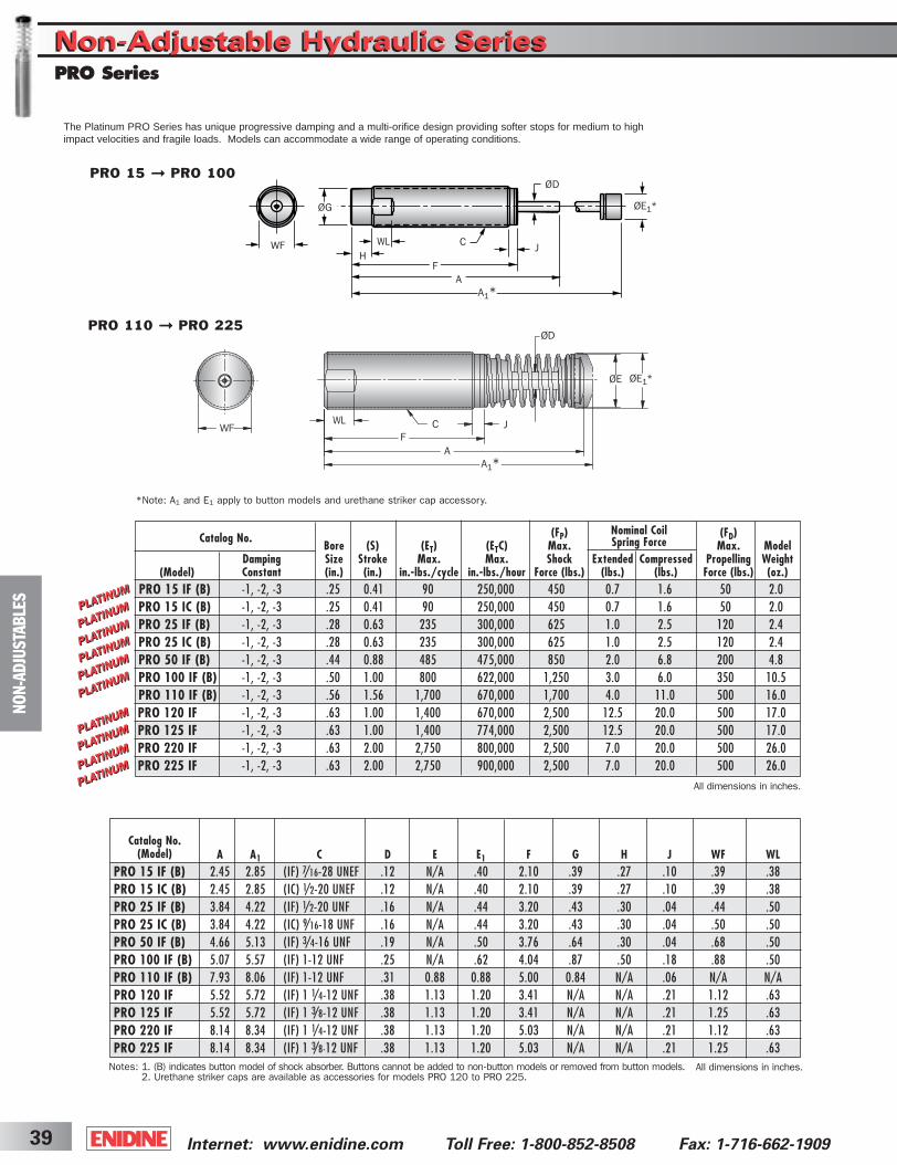
Internet: www.enidine.com Toll Free: 1-800-852-8508 Fax: 1-716-662-190939
NO
N-A
DJU
STA
BLE
S
PRO 15 ➞ PRO 100
PRO 110 ➞ PRO 225
Nominal Coil Spring ForceCatalog No.
(Model)
All dimensions in inches.
All dimensions in inches.
Catalog No.(Model)
Notes: 1. (B) indicates button model of shock absorber. Buttons cannot be added to non-button models or removed from button models.2. Urethane striker caps are available as accessories for models PRO 120 to PRO 225.
FA
A1*
ØD
C J
J
WFWL
ØE1*ØE
ØE1*ØG
FA
A1*
ØD
CWFH
WL
The Platinum PRO Series has unique progressive damping and a multi-orifice design providing softer stops for medium to highimpact velocities and fragile loads. Models can accommodate a wide range of operating conditions.
PRO SeriesNon-Adjustable Hydraulic SeriesNon-Adjustable Hydraulic Series
*Note: A1 and E1 apply to button models and urethane striker cap accessory.
A A1 C D E E1 F G H J WF WLPRO 15 IF (B) 2.45 2.85 (IF) 7/16-28 UNEF .12 N/A .40 2.10 .39 .27 .10 .39 .38PRO 15 IC (B) 2.45 2.85 (IC) 1/2-20 UNEF .12 N/A .40 2.10 .39 .27 .10 .39 .38PRO 25 IF (B) 3.84 4.22 (IF) 1/2-20 UNF .16 N/A .44 3.20 .43 .30 .04 .44 .50PRO 25 IC (B) 3.84 4.22 (IC) 9/16-18 UNF .16 N/A .44 3.20 .43 .30 .04 .50 .50PRO 50 IF (B) 4.66 5.13 (IF) 3/4-16 UNF .19 N/A .50 3.76 .64 .30 .04 .68 .50PRO 100 IF (B) 5.07 5.57 (IF) 1-12 UNF .25 N/A .62 4.04 .87 .50 .18 .88 .50PRO 110 IF (B) 7.93 8.06 (IF) 1-12 UNF .31 0.88 0.88 5.00 0.84 N/A .06 N/A N/APRO 120 IF 5.52 5.72 (IF) 1 1/4-12 UNF .38 1.13 1.20 3.41 N/A N/A .21 1.12 .63PRO 125 IF 5.52 5.72 (IF) 1 3/8-12 UNF .38 1.13 1.20 3.41 N/A N/A .21 1.25 .63PRO 220 IF 8.14 8.34 (IF) 1 1/4-12 UNF .38 1.13 1.20 5.03 N/A N/A .21 1.12 .63PRO 225 IF 8.14 8.34 (IF) 1 3/8-12 UNF .38 1.13 1.20 5.03 N/A N/A .21 1.25 .63
(FP) (FD)Bore (S) (ET) (ETC) Max. Max. Model
Damping Size Stroke Max. Max. Shock Extended Compressed Propelling WeightConstant (in.) (in.) in.-lbs./cycle in.-lbs./hour Force (lbs.) (lbs.) (lbs.) Force (lbs.) (oz.)
PRO 15 IF (B) -1, -2, -3 .25 0.41 90 250,000 450 0.7 1.6 50 2.0 PRO 15 IC (B) -1, -2, -3 .25 0.41 90 250,000 450 0.7 1.6 50 2.0 PRO 25 IF (B) -1, -2, -3 .28 0.63 235 300,000 625 1.0 2.5 120 2.4PRO 25 IC (B) -1, -2, -3 .28 0.63 235 300,000 625 1.0 2.5 120 2.4PRO 50 IF (B) -1, -2, -3 .44 0.88 485 475,000 850 2.0 6.8 200 4.8PRO 100 IF (B) -1, -2, -3 .50 1.00 800 622,000 1,250 3.0 6.0 350 10.5PRO 110 IF (B) -1, -2, -3 .56 1.56 1,700 670,000 1,700 4.0 11.0 500 16.0PRO 120 IF -1, -2, -3 .63 1.00 1,400 670,000 2,500 12.5 20.0 500 17.0PRO 125 IF -1, -2, -3 .63 1.00 1,400 774,000 2,500 12.5 20.0 500 17.0PRO 220 IF -1, -2, -3 .63 2.00 2,750 800,000 2,500 7.0 20.0 500 26.0PRO 225 IF -1, -2, -3 .63 2.00 2,750 900,000 2,500 7.0 20.0 500 26.0
ShockCover5-2B 3/31/03 2:29 PM Page 39
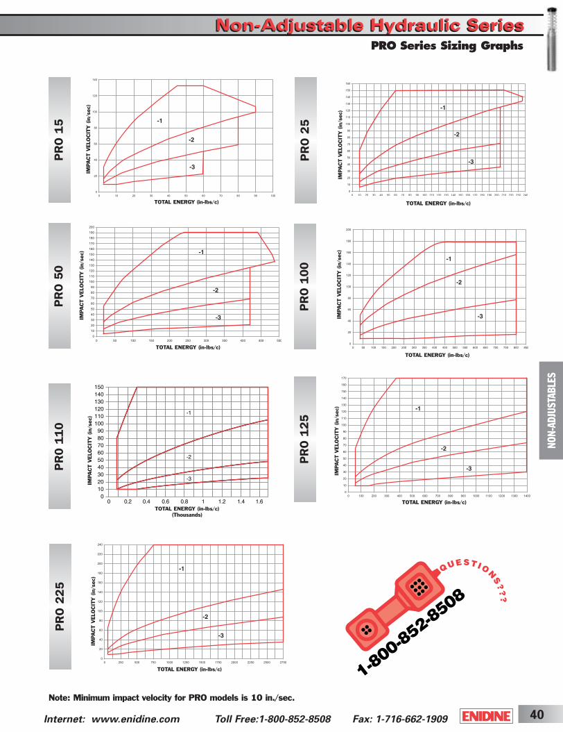
40Internet: www.enidine.com Toll Free:1-800-852-8508 Fax: 1-716-662-1909
NO
N-A
DJU
STA
BLE
S
PRO Series Sizing Graphs
Non-Adjustable Hydraulic SeriesNon-Adjustable Hydraulic Series
PR
O 1
5
PR
O 2
5
PR
O 5
0
PR
O 1
00
PR
0 1
10
PR
O 1
25
PR
O 2
25
Note: Minimum impact velocity for PRO models is 10 in./sec.
TOTAL ENERGY (in-lbs/c)
IMPACT V
ELO
CIT
Y (
in/s
ec)
TOTAL ENERGY (in-lbs/c)
IMPACT V
ELO
CIT
Y (
in/s
ec)
TOTAL ENERGY (in-lbs/c)
IMPACT V
ELO
CIT
Y (
in/s
ec)
TOTAL ENERGY (in-lbs/c)(Thousands)
IMPACT V
ELO
CIT
Y (
in/s
ec)
TOTAL ENERGY (in-lbs/c)
IMPACT V
ELO
CIT
Y (
in/s
ec)
TOTAL ENERGY (in-lbs/c)
IMPACT V
ELO
CIT
Y (
in/s
ec)
TOTAL ENERGY (in-lbs/c)
IMPACT V
ELO
CIT
Y (
in/s
ec)
ShockCover5-2B 3/31/03 2:29 PM Page 40
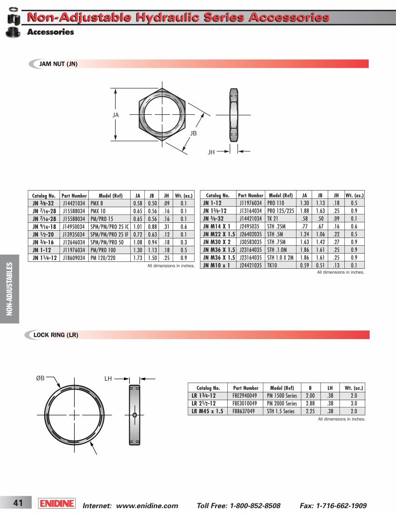
Internet: www.enidine.com Toll Free: 1-800-852-8508 Fax: 1-716-662-190941
Catalog No. Part Number Model (Ref) B LH Wt. (oz.)LR 13⁄4-12 F8E2940049 PM 1500 Series 2.00 .38 2.0LR 21⁄2-12 F8E3010049 PM 2000 Series 2.88 .38 3.0LR M45 x 1.5 F88637049 STH 1.5 Series 2.25 .38 2.0
LOCK RING (LR)
All dimensions in inches.
ØB LH
NO
N-A
DJU
STA
BLE
S
Non-Adjustable Hydraulic Series AccessoriesNon-Adjustable Hydraulic Series AccessoriesAccessories
JA
JB
JH
Catalog No. Part Number Model (Ref) JA JB JH Wt. (oz.)JN 1-12 J11976034 PRO 110 1.30 1.13 .18 0.5JN 13⁄8-12 J13164034 PRO 125/225 1.88 1.63 .25 0.9JN 3⁄8-32 J14421034 TK 21 .58 .50 .09 0.1JN M14 X 1 J2495035 STH .25M .77 .67 .16 0.6JN M22 X 1.5 J26402035 STH .5M 1.24 1.06 .22 0.5JN M30 X 2 J30583035 STH .75M 1.63 1.42 .27 0.9JN M36 X 1.5 J23164035 STH .1.0M 1.86 1.61 .25 0.9JN M36 X 1.5 J23164035 STH 1.0 X 2M 1.86 1.61 .25 0.9JN M10 x 1 J24421035 TK10 0.59 0.51 .13 0.1
All dimensions in inches.All dimensions in inches.
JAM NUT (JN)
Catalog No. Part Number Model (Ref) JA JB JH Wt. (oz.)JN 3⁄8-32 J14421034 PMX 8 0.58 0.50 .09 0.1JN 7⁄16-28 J15588034 PMX 10 0.65 0.56 .16 0.1JN 7⁄16-28 J15588034 PM/PRO 15 0.65 0.56 .16 0.1JN 9⁄16-18 J14950034 SPM/PM/PRO 25 IC 1.01 0.88 .31 0.6JN 1⁄2-20 J13935034 SPM/PM/PRO 25 IF 0.72 0.63 .12 0.1JN 3⁄4-16 J12646034 SPM/PM/PRO 50 1.08 0.94 .18 0.3JN 1-12 J11976034 PM/PRO 100 1.30 1.13 .18 0.5JN 11⁄4-12 J18609034 PM 120/220 1.73 1.50 .25 0.9
ShockCover5-2B 3/31/03 2:29 PM Page 41
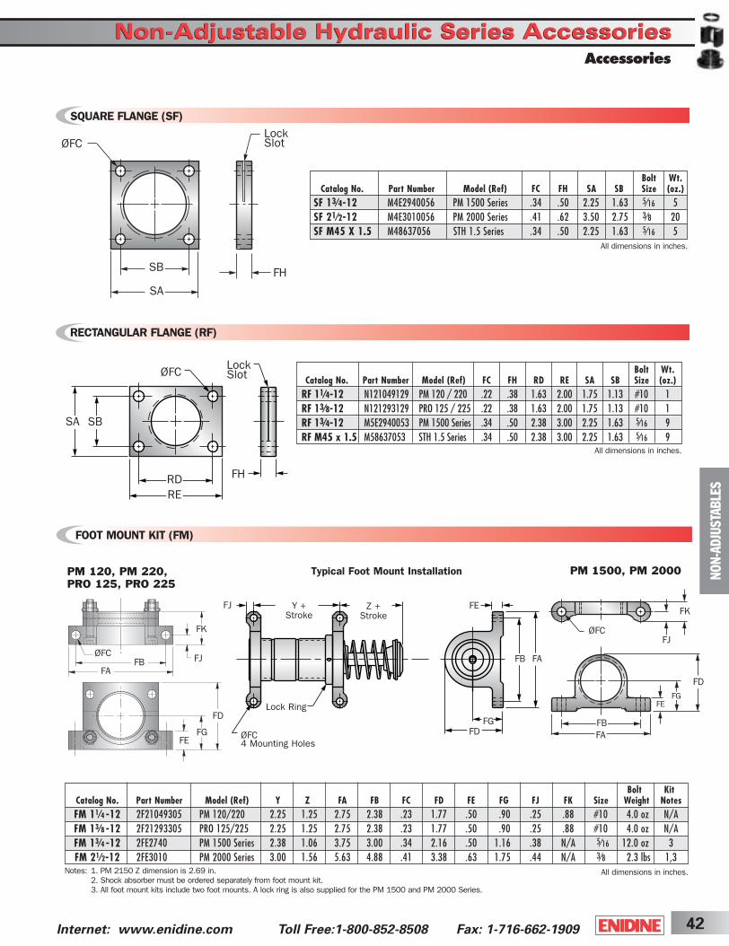
FD
FGFE
FA
FB
FK
FJøFC
42Internet: www.enidine.com Toll Free:1-800-852-8508 Fax: 1-716-662-1909
Bolt KitCatalog No. Part Number Model (Ref) Y Z FA FB FC FD FE FG FJ FK Size Weight NotesFM 11⁄4 -12 2F21049305 PM 120/220 2.25 1.25 2.75 2.38 .23 1.77 .50 .90 .25 .88 #10 4.0 oz N/AFM 13⁄8 -12 2F21293305 PRO 125/225 2.25 1.25 2.75 2.38 .23 1.77 .50 .90 .25 .88 #10 4.0 oz N/AFM 13⁄4 -12 2FE2740 PM 1500 Series 2.38 1.06 3.75 3.00 .34 2.16 .50 1.16 .38 N/A 5⁄16 12.0 oz 3FM 21⁄2-12 2FE3010 PM 2000 Series 3.00 1.56 5.63 4.88 .41 3.38 .63 1.75 .44 N/A 3⁄8 2.3 lbs 1,3
FOOT MOUNT KIT (FM)
SQUARE FLANGE (SF)
RECTANGULAR FLANGE (RF)
All dimensions in inches.
FJ Y +Stroke
Z +Stroke
ØFC4 Mounting Holes
FAFB
FGFD
FE
RDRE
FH
LockSlot
SBSA
ØFC
PM 1500, PM 2000
FB
FE
FJ
FG
FA
FD
PM 120, PM 220,PRO 125, PRO 225
ØFC
FK
Typical Foot Mount Installation
Lock Ring
All dimensions in inches.
Notes: 1. PM 2150 Z dimension is 2.69 in.2. Shock absorber must be ordered separately from foot mount kit.3. All foot mount kits include two foot mounts. A lock ring is also supplied for the PM 1500 and PM 2000 Series.
NO
N-A
DJU
STA
BLE
S
ØFC
SB
SA
FH
LockSlot
Bolt Wt.Catalog No. Part Number Model (Ref) FC FH SA SB Size (oz.)
SF 13⁄4-12 M4E2940056 PM 1500 Series .34 .50 2.25 1.63 5⁄16 5SF 21⁄2-12 M4E3010056 PM 2000 Series .41 .62 3.50 2.75 3⁄8 20SF M45 X 1.5 M48637056 STH 1.5 Series .34 .50 2.25 1.63 5⁄16 5
All dimensions in inches.
Accessories
Non-Adjustable Hydraulic Series AccessoriesNon-Adjustable Hydraulic Series Accessories
FD
FBFA
FK
FE
FJ
FG
ØFC
Bolt Wt.Catalog No. Part Number Model (Ref) FC FH RD RE SA SB Size (oz.)
RF 11⁄4-12 N121049129 PM 120 / 220 .22 .38 1.63 2.00 1.75 1.13 #10 1RF 13⁄8-12 N121293129 PRO 125 / 225 .22 .38 1.63 2.00 1.75 1.13 #10 1RF 13⁄4-12 M5E2940053 PM 1500 Series .34 .50 2.38 3.00 2.25 1.63 5⁄16 9RF M45 x 1.5 M58637053 STH 1.5 Series .34 .50 2.38 3.00 2.25 1.63 5⁄16 9
ShockCover5-2B 3/31/03 2:29 PM Page 42
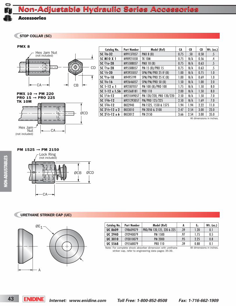
Internet: www.enidine.com Toll Free: 1-800-852-8508 Fax: 1-716-662-190943
URETHANE STRIKER CAP (UC)
All dimensions in inches.Note: For complete shock absorber dimension with urethanestriker cap, refer to engineering data pages 35-39.
STOP COLLAR (SC)
All dimensions in inches.
A
ØE1
PMX 10 ➞ PM 220PRO 15 ➞ PRO 225TK 10M
PMX 8
PM 1525 ➞ PM 2150
CA
ØCD
Hex Jam Nut(not included)
CA CB
Lock Ring(not included)
CA
ØCB ØCD
Hex JamNut
(not included)
CD
NO
N-A
DJU
STA
BLE
S
Non-Adjustable Hydraulic Series AccessoriesNon-Adjustable Hydraulic Series AccessoriesAccessories
Catalog No. Part Number Model (Ref) CA CB CD Wt. (oz.)SC 3⁄8-32 M99137057 PMX 8 (B) 0.75 .50 0.58 .5SC M10 X 1 M98921058 TK 10M 0.75 N/A 0.56 .4SC 7⁄16-28 M95588057 PMX 10 (B) 0.75 N/A 0.63 .5SC 7⁄16-28 M95588057 PM 15 (B)/PRO 15 0.75 N/A 0.63 .5SC 1⁄2-20 M93935057 SPM/PM/PRO 25 IF (B) 1.00 N/A 0.75 1.0SC 9⁄16-18 M9495199 SPM/PM/PRO 25 IC (B) 1.00 N/A 0.69 1.0SC 3⁄4-16 M92646057 SPM/PM/PRO 50 (B) 1.50 N/A 1.00 2.0SC 1-12 x 1 M92587057 PM 100 (B)/PRO 100 1.75 N/A 1.50 8.0SC 1-12 x 1.56 M95568181 PRO 110 2.00 N/A 1.50 8.0SC 11⁄4-12 M921049057 PM 120/220, PRO 120/220 2.50 N/A 1.50 7.0SC 13⁄8-12 M921293057 PM/PRO 125/225 2.50 N/A 1.69 7.0SC 13⁄4-12 8KE2940 PM 1525, 1550 & 1575 1.94 1.94 2.22 11.0SC 21⁄2-12 x 2 8KE3010 PM 2050 & 2100 2.47 2.54 3.00 23.0SC 21⁄2-12 x 6 8KE3012 PM 2150 3.66 2.54 3.00 35.0
Catalog No. Part Number Model (Ref) A E1 Wt. (oz.) UC 8609 C98609079 PRO/PM 120,125, 220 & 225 .39 1.20 0.1UC 2940 C92940079 PM 1500 .97 1.75 0.5UC 3010 C93010079 PM 2000 .95 2.25 0.8UC 5568 C95568079 PRO 110 .39 0.88 0.1
ShockCover5-2B 3/31/03 2:29 PM Page 43
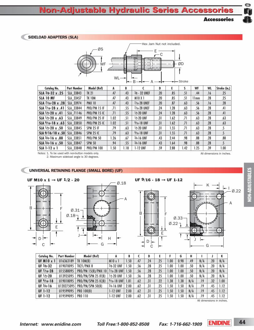
44Internet: www.enidine.com Toll Free:1-800-852-8508 Fax: 1-716-662-1909
UNIVERSAL RETAINING FLANGE (SMALL BORE) (UF)
F
E
B
D
C
Ø.31Ø.18
J
GH
A
Ø.18
F
E
B
DC
Ø.33Ø.22
J
G
K
A
IØ.22
UF M10 x 1 ➞ UF 1/2 - 20 UF 9/16 - 18 ➞ UF 1-12
SIDELOAD ADAPTERS (SLA)
ØS
WF
EC
ØD
WLB A Stroke
All dimensions in inches.Notes: 1. To be used with non-button models only. 2. Maximum sideload angle is 30 degrees.
All dimensions in inches.
NO
N-A
DJU
STA
BLE
S
Hex Jam Nut not included.
Catalog No. Part Number Model (Ref) A B C D E F G H I J KUF M10 x 1 U16363189 TK 10M(B) M10 x 1 1.50 .47 .24 .25 1.00 0.98 .49 N/A .20 N/AUF 3⁄8-32 U19070095 TK21/PMX 8 3⁄8-32 UNF 1.50 .56 .28 .25 1.00 1.00 .50 N/A .20 N/AUF 7⁄16-28 U15588095 PRO/PM 15(B)/PMX 10 7⁄16-28 UNF 1.50 .56 .28 .25 1.00 1.00 .50 N/A .20 N/AUF 1⁄2-20 U13935095 PRO/PM/SPM 25 IF(B) 1⁄2-20 UNF 1.50 .56 .28 .25 1.00 1.00 .50 N/A .20 N/AUF 9⁄16-18 U19018095 PRO/PM/SPM 25 IC(B) 9⁄16-18 UNF 1.81 .62 .31 .22 1.38 1.38 N/A .19 .32 1.00UF 3⁄4-16 U120275095 PRO/PM/SPM 50(B) 3⁄4-16 UNF 2.00 .62 .31 .25 1.50 1.50 N/A .19 .45 1.12UF 1-12 U19599095 PRO 100(B) 1-12 UNF 2.00 .62 .31 .25 1.50 1.50 N/A .19 .45 1.12UF 1-12 U19599095 PRO 110 1-12 UNF 2.00 .62 .31 .25 1.50 1.50 N/A .19 .45 1.12
Accessories
Non-Adjustable Hydraulic Series AccessoriesNon-Adjustable Hydraulic Series Accessories
Catalog No. Part Number Model (Ref) A B C D E S WF WL Stroke (in.)SLA 3⁄8-32 x .25 SLA_33843 TK 21 .47 .43 3⁄8 - 32 UNEF .20 .85 .51 .44 .16 .25SLA 10 MF SLA_33457 TK 10M .47 .43 M10 X 1 .20 .85 .51 11mm .28 .25SLA 7⁄16-28 x .28 SLA_33974 PMX 10 .47 .43 7⁄16-28 UNEF .20 .87 .63 .56 .16 .28SLA 7⁄16-28 x .41 SLA_33844 PRO/PM 15 IF .71 .55 7⁄16-28 UNEF .24 1.28 .63 .56 .28 .41SLA 1⁄2-20 x .41 SLA_71146 PRO/PM 15 IC .71 .55 1⁄2-20 UNF .24 1.28 .63 .56 .28 .41SLA 1⁄2-20 x .63 SLA_33849 PRO/PM 25 IF 1.02 .51 1⁄2-20 UNF .31 1.62 .71 .63 .28 .63SLA 9⁄16-18 x .63 SLA_33850 PRO/PM 25 IC 1.02 .51 9⁄16-18 UNF .31 1.62 .71 .63 .28 .63SLA 1⁄2-20 x .50 SLA_33845 SPM 25 IF .79 .63 1⁄2-20 UNF .31 1.55 .71 .63 .28 .5SLA 9⁄16 ⁄ 18 x .50 SLA_33846 SPM 25 IC .79 .63 9⁄16-18 UNF .31 1.55 .71 .63 .28 .5SLA 3⁄4-16 x .88 SLA_33851 PRO/PM 50 1.26 .67 3⁄4-16 UNF .43 2.44 .98 .88 .28 .88SLA 3⁄4-16 x .50 SLA_33847 SPM 50 .94 .55 3⁄4-16 UNF .43 1.64 .98 .88 .28 .5SLA 1-12 x 1 SLA_33848 PRO/PM 100 1.50 1.18 1-12 UNF .59 2.88 1.42 1.25 .39 1.00
ShockCover5-2B 3/31/03 2:29 PM Page 44

Internet: www.enidine.com Toll Free: 1-800-852-8508 Fax: 1-716-662-190945
All dimensions in inches.Note: (S) indicates model comes with spring.
ModelWeight(lbs.)
X
ØN
WPL
ØS
ØM
PM 120 CM ➞ PM 225 CMPRO 110 CM ➞ PRO 225 CM
ØU
VQ
CR
PM 1525 CM ➞ PM 2150 CM
R
ØN
WP
L
ØS
ØM
U
V
Q
CR
ØT
Lock Ring SpringOptional
Spring Optional Jam Nut
NO
N-A
DJU
STA
BLE
S
Clevis Mounting
Catalog No. (Model) L M N P Q R S T U V W X CR
PM/PRO 120 CM (S) 6.59 .251 .251 .500 .500 N/A 1.50 N/A .88 .23 .48 .31 .44 1.3+.005/-.000 +.005/-.000 +.000/-.010 +.000/-.010
PM/PRO 220 CM (S) 9.22 .251 .251 .500 .500 N/A 1.50 N/A .88 .23 .48 .31 .44 1.7+.005/-.000 +.005/-.000 +.000/-.010 +.000/-.010
PM 1525 CM (S) 7.84 .376 .501 .750 1.00 .505 2.00 1.00 1.00 1.01 .87 N/A .56 3.0+.010/-.000 +.010/-.000 +.000/-.010 +.020/-.000
PM 1550 CM (S) 9.84 .376 .501 .750 1.00 .505 2.00 1.00 1.00 1.01 .87 N/A .56 3.2+.010/-.000 +.010/-.000 +.000/-.010 +.020/-.000
PM 1575 CM (S) 11.84 .376 .501 .750 1.00 .505 2.00 1.00 1.00 1.01 .87 N/A .56 3.6+.010/-.000 +.010/-.000 +.000/-.010 +.020/-.000
PM 2050 CM (S) 12.06 .751 .751 1.250 1.50 .630 2.88 1.50 1.50 1.40 1.06 N/A .90 8.2+.010/-.000 +.010/-.000 +.000/-.010 +.020/-.000
PM 2100 CM (S) 16.06 .751 .751 1.250 1.50 .630 2.88 1.50 1.50 1.40 1.06 N/A .90 9.3+.010/-.000 +.010/-.000 +.000/-.010 +.020/-.000
PM 2150 CM (S) 21.13 .751 .751 1.250 1.50 .630 2.88 1.50 1.50 1.40 1.06 N/A .90 11.2+.010/-.000 +.010/-.000 +.000/-.010 +.020/-.000
PRO 110 CM (S) 8.32 .197 .251 .375 .315 N/A 1.25 N/A .88 .42 .51 .25 .25 1.2+.005/-.000 +.005/-.000 +.000/-.010 +.000/-.010
PM/PRO 125 CM (S) 6.59 .251 .251 .500 .500 N/A 1.50 N/A .88 .23 .93 .23 .44 1.6+.005/-.000 +.005/-.000 +.000/-.010 +.000/-.010
PM/PRO 225 CM (S) 9.22 .251 .251 .500 .500 N/A 1.50 N/A .88 .23 .93 .23 .44 1.9+.005/-.000 +.005/-.000 +.000/-.010 +.000/-.010
Non-Adjustable Hydraulic Series AccessoriesNon-Adjustable Hydraulic Series Accessories
ShockCover5-2B 3/31/03 2:29 PM Page 45

10 PRO 50 IF 2 B STH .25
46Internet: www.enidine.com Toll Free:1-800-852-8508 Fax: 1-716-662-1909
SHOCK ABSORBER ORDERING INFORMATION
ACCESSORIES
Example 1:Standard Products
-Select quantity
Selectcatalognumber
Select threaddesignationfrom engineeringdata chart(If applicable)
Select dampingconstant from appropriatesizing graph
Select piston rod type• “–” (without button)• “B” (with button)• “CM” (Clevis mount)
Example 2:Custom Orifice Products*
10 APPLICATIONDATA
Select quantity
Selectcatalognumber
*Enidine will specify individual part number for each application.
Specify:• Vertical, rotary or horizontal motion• Weight• Impact velocity• Propelling force (if any)• Other (temperature or other
environmental conditions)• Cycles per hour
Example 1
10 UF -16(P/N U120275095) (P/N C98609079)Select
quantity
Select catalog/part number
Universal Mounting Flange
Example 2
5 UC 8609Select quantity
Urethane Striker Cap3⁄4
Select catalog /part number
NO
N-A
DJU
STA
BLE
S
Ordering InformationNon-Adjustable Hydraulic SeriesNon-Adjustable Hydraulic Series
ShockCover5-2B 3/31/03 2:29 PM Page 46
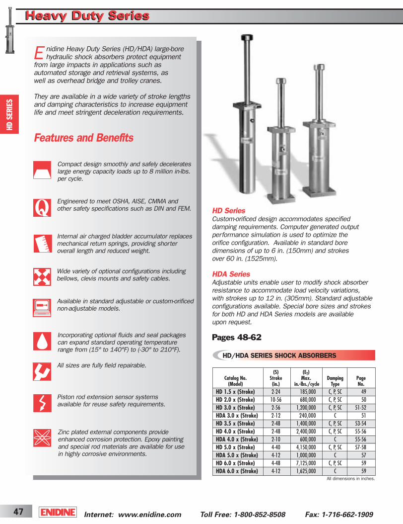
HD SeriesCustom-orificed design accommodates specified damping requirements. Computer generated output performance simulation is used to optimize the orifice configuration. Available in standard bore dimensions of up to 6 in. (150mm) and strokes over 60 in. (1525mm).
HDA SeriesAdjustable units enable user to modify shock absorber resistance to accommodate load velocity variations, with strokes up to 12 in. (305mm). Standard adjustable configurations available. Special bore sizes and strokes for both HD and HDA Series models are available upon request.
Pages 48-62
Internet: www.enidine.com Toll Free: 1-800-852-8508 Fax: 1-716-662-190947
Features and Benefits
Compact design smoothly and safely decelerateslarge energy capacity loads up to 8 million in-lbs. per cycle.
E nidine Heavy Duty Series (HD/HDA) large-borehydraulic shock absorbers protect equipment
from large impacts in applications such as automated storage and retrieval systems, as well as overhead bridge and trolley cranes.
They are available in a wide variety of stroke lengthsand damping characteristics to increase equipmentlife and meet stringent deceleration requirements.
Engineered to meet OSHA, AISE, CMMA and other safety specifications such as DIN and FEM.
Internal air charged bladder accumulator replacesmechanical return springs, providing shorter overall length and reduced weight.
Wide variety of optional configurations including bellows, clevis mounts and safety cables.
Available in standard adjustable or custom-orificednon-adjustable models.
Zinc plated external components provide enhanced corrosion protection. Epoxy painting and special rod materials are available for use in highly corrosive environments.
Incorporating optional fluids and seal packagescan expand standard operating temperaturerange from (15° to 140°F) to (-30° to 210°F).
All sizes are fully field repairable.
Piston rod extension sensor systemsavailable for reuse safety requirements.
HD
SERIE
S
Heavy Duty SeriesHeavy Duty Series
All dimensions in inches.
(S) (ET)Catalog No. Stroke Max. Damping Page
(Model) (in.) in.-lbs./cycle Type No.HD 1.5 x (Stroke) 2-24 185,000 C, P, SC 49HD 2.0 x (Stroke) 10-56 680,000 C, P, SC 50HD 3.0 x (Stroke) 2-56 1,200,000 C, P, SC 51-52HDA 3.0 x (Stroke) 2-12 240,000 C 51HD 3.5 x (Stroke) 2-48 1,400,000 C, P, SC 53-54HD 4.0 x (Stroke) 2-48 2,400,000 C, P, SC 55-56HDA 4.0 x (Stroke) 2-10 600,000 C 55-56HD 5.0 x (Stroke) 4-40 4,150,000 C, P, SC 57-58HDA 5.0 x (Stroke) 4-12 1,000,000 C 57HD 6.0 x (Stroke) 4-48 7,125,000 C, P, SC 59HDA 6.0 x (Stroke) 4-12 1,625,000 C 59
HD/HDA SERIES SHOCK ABSORBERS
ShockCover5-2B 3/31/03 2:29 PM Page 47

48Internet: www.enidine.com Toll Free:1-800-852-8508 Fax: 1-716-662-1909
HD
SERIE
S
Heavy Duty SeriesHeavy Duty Series
Gas Charge Valve
Shock Tube Piston Head
Piston Rod
Orifice Holes Cylinder
OilBladder Accumulator
Check Ring
BearingFill Plug
Heavy Duty Large Bore (HD/HDA) SeriesShock AbsorbersThe Enidine HD/HDA Series is a large bore, multi-orificefamily of shock absorbers which incorporates a double cylinder arrangement with space between the concentricshock tube and cylinder, and a series of orifice holes drilleddown the length of the shock tube wall.
During piston movement, the check ring is seated and oil is forced through the orifices in the shock tube wall, into the gas charged bladder/accumulator area, and behind thepiston head. The orifice area decreases as the piston movesand closes the orifice holes. The bladder/accumulator isalso compressed by the oil during the compression stroke,which compensates for the fluid displaced by the piston rodduring compression.
During repositioning, the pressure from the bladder/accumulator pushes the piston rod outward. This unseatsthe check ring and permits oil to flow rapidly through the piston head into the front of the shock tube. The uniquegas-charged bladder accumulator replaces mechanical returnsprings, decreasing overall product size and weight.
The HD/HDA Series can provide conventional, progressive or self-compensating damping. Their compact, heavy-dutydesign (non-adjustable shown below) safely and effectivelydecelerates large moving loads, with energy capacities of upto eight million in-lbs per cycle.
HD/HDA Series Shock Absorber Sizing1. Determine load weight (lbs.), impact velocity (in./sec),
propelling force (lbs.) if any, cycles per hour and stroke(in.) required.
2. Calculate total energy per cycle (in.-lbs./c) and total energy per hour (in.-lbs./hr). Consult this catalog’s sizingexamples (pages 5-12) for assistance, if required.
3. Compare the calculated total energy per cycle (in-lbs./c)and total energy per hour (in.-lbs./hr), to the values listedin the HD/HDA Series Engineering Data charts. For HDAselection, the impact velocity must be below 130 in./sec.
4. Select the appropriate HD/HDA Series model.
Example: Horizontal Application
1. Weight (W): 55,000 lbs.Velocity (V): 43 in./sec.Propelling Force (FD): 6,700 lbs.Cycles/Hour (C): 10 cycles/hrStroke (S): 5 in.
2. Total Energy/Cycle (ET): 165,229 in.-lbs./cTotal Energy/Hour (ETC): 1,652,290 in.-lbs./hr
3. Compare total energy per cycle (165,229 in.-lbs./c) andtotal energy per hour (1,652,290 in.-lbs./hr) to theHD/HDA Series Engineering Data charts (pages 49-60).
4. Selection: HD 3.0 x 5 (HDA is not appropriate because maximum in.-lbs. per cycle are exceeded).
Design Profiles
ShockCover5-2B 3/31/03 2:29 PM Page 48

Internet: www.enidine.com Toll Free: 1-800-852-8508 Fax: 1-716-662-190949
ØFC
SASB
SASB
AF
ØDØBH
ØE
Z
Ø1.0CB
CC
CA
Notes: 1. HD shock absorbers will function satisfactorily at 5% of their maximum rated energy per cycle. If less than these values, a smaller model should be specified.
2. It is recommended that the customer consult Enidine for safety-related overhead crane applications.3. The energy data listed is for ideal linear impacts only. If side load conditions exist in the application, contact Enidine for sizing assistance. 4. Rear flange mounting of 12 inch strokes and longer not recommended. Front and rear flange or foot mount configurations are recommended.5. Maximum cycle rate is 60 cycles/hr.
Note: For TF, FF and FR mounting, delete front foot and dimensions.
HD
SERIE
S
Charge PortDimensionsFoot Mount Dimensions
Flange Dimensions
HD 1.5 x 2 ➞ HD 1.5 x 24
Heavy Duty SeriesHeavy Duty SeriesHD Series
FB
FE
Charge Port
FJ Y
Fill Port
ZFA
FGFD
ØFC
FJ
All dimensions in inches.
Catalog No. A B D E F H Y Z(Model) FA FB FC FD FE FG FJ CA CB CC
HD 1.5 x 2 12.2 3.5 1.1 2.0 8.2 0.8 9.4 3.4 6.5 5.5 .55 4.9 1.3 2.5 .63 5.7 2.2 45°HD 1.5 x 4 16.1 3.5 1.1 2.0 10.2 0.8 11.4 5.3 6.5 5.5 .55 4.9 1.3 2.5 .63 5.7 2.2 45°HD 1.5 x 6 20.1 3.5 1.1 2.0 12.2 0.8 13.4 7.3 6.5 5.5 .55 4.9 1.3 2.5 .63 5.7 2.2 45°HD 1.5 x 8 24.1 3.5 1.1 2.0 14.2 0.8 15.4 9.3 6.5 5.5 .55 4.9 1.3 2.5 .63 5.7 2.2 45°HD 1.5 x 10 28.2 3.5 1.1 2.0 16.2 0.8 17.4 11.4 6.5 5.5 .55 4.9 1.3 2.5 .63 5.7 2.2 45°HD 1.5 x 12 32.2 3.5 1.1 2.0 18.2 0.8 19.4 13.4 6.5 5.5 .55 4.9 1.3 2.5 .63 5.7 2.2 45°HD 1.5 x 14 36.1 3.5 1.1 2.0 20.2 0.8 21.4 15.3 6.5 5.5 .55 4.9 1.3 2.5 .63 5.7 2.2 45°HD 1.5 x 16 40.1 3.5 1.1 2.0 22.2 0.8 23.4 17.3 6.5 5.5 .55 4.9 1.3 2.5 .63 5.7 2.2 45°HD 1.5 x 18 44.1 3.5 1.1 2.0 24.2 0.8 25.4 19.3 6.5 5.5 .55 4.9 1.3 2.5 .63 5.7 2.2 45°HD 1.5 x 20 48.2 3.5 1.1 2.0 26.2 0.8 27.4 21.4 6.5 5.5 .55 4.9 1.3 2.5 .63 5.7 2.2 45°HD 1.5 x 24 56.2 3.5 1.1 2.0 30.2 0.8 31.4 25.4 6.5 5.5 .55 4.9 1.3 2.5 .63 5.7 2.2 45°
(FP) NominalBore (S) (ET) (ETC) Max. Return Rec. Model
Catalog No. Size Stroke Max. Max. Shock Force Force Bolt Weight (Model) (in.) (in.) in.-lbs./cycle in.-lbs./hour (lbs.) (lbs.) SA SB Size (lbs.)
HD 1.5 x 2 1.57 2 27,000 1,590,000 15,750 63 4.7 3.5 1/2 22HD 1.5 x 4 1.57 4 53,000 3,160,000 15,750 63 4.7 3.5 1/2 24HD 1.5 x 6 1.57 6 79,000 4,742,000 15,750 63 4.7 3.5 1/2 26HD 1.5 x 8 1.57 8 106,000 6,319,000 15,750 63 4.7 3.5 1/2 29HD 1.5 x 10 1.57 10 132,000 7,426,000 15,750 63 4.7 3.5 1/2 31HD 1.5 x 12 1.57 12 158,000 8,315,000 15,750 63 4.7 3.5 1/2 35HD 1.5 x 14 1.57 14 184,000 9,187,000 15,750 63 4.7 3.5 1/2 37HD 1.5 x 16 1.57 16 180,000 10,076,000 13,500 63 4.7 3.5 1/2 40HD 1.5 x 18 1.57 18 162,000 9,717,000 10,750 63 4.7 3.5 1/2 42HD 1.5 x 20 1.57 20 146,000 8,761,000 8,750 63 4.7 3.5 1/2 44HD 1.5 x 24 1.57 24 126,000 7,540,000 6,250 63 4.7 3.5 1/2 50
ShockCover5-2B 3/31/03 2:30 PM Page 49

ØFC
SASB
SASB
AF
ØDØBH
ØE
Z
Ø1.0CB
CC
CA
50Internet: www.enidine.com Toll Free:1-800-852-8508 Fax: 1-716-662-1909
All dimensions in inches.Notes: 1. HD shock absorbers will function satisfactorily at 5% of their maximum rated energy per cycle. If less than these values, a smaller model should be specified.
2. It is recommended that the customer consult Enidine for safety-related overhead crane applications.3. The energy data listed is for ideal linear impacts only. If side load conditions exist in the application, contact Enidine for sizing assistance. 4. Rear flange mounting of 12 inch strokes and longer not recommended. Front and rear flange or foot mount configurations are recommended.5. Maximum cycle rate is 60 cycles/hr.
Note: For TF, FF and FR mounting, delete front foot and dimensions.
HD
SERIE
S
Charge PortDimensionsFoot Mount Dimensions
HD 2.0 x 10 ➞ HD 2.0 x 56
Heavy Duty SeriesHeavy Duty SeriesHD Series
FB
FE
Charge Port
FJ Y
Fill Port
ZFA
FGFD
ØFC
FJ
Catalog No. A B D E F H Y Z(Model) FA FB FC FD FE FG FJ CA CB CC
HD 2.0 x 10 29.8 4.3 1.6 2.4 17.4 1.0 19.0 11.6 8.7 7.0 .67 5.8 1.6 3.0 .80 7.2 2.6 30°HD 2.0 x 12 33.8 4.3 1.6 2.4 19.4 1.0 21.0 13.6 8.7 7.0 .67 5.8 1.6 3.0 .80 7.2 2.6 30°HD 2.0 x 14 37.8 4.3 1.6 2.4 21.4 1.0 23.0 15.6 8.7 7.0 .67 5.8 1.6 3.0 .80 7.2 2.6 30°HD 2.0 x 16 41.8 4.3 1.6 2.4 23.4 1.0 25.0 17.6 8.7 7.0 .67 5.8 1.6 3.0 .80 7.2 2.6 30°HD 2.0 x 18 45.8 4.3 1.6 2.4 25.4 1.0 27.0 19.6 8.7 7.0 .67 5.8 1.6 3.0 .80 7.2 2.6 30°HD 2.0 x 20 49.8 4.3 1.6 2.4 27.4 1.0 29.0 21.6 8.7 7.0 .67 5.8 1.6 3.0 .80 7.2 2.6 30°HD 2.0 x 24 57.8 4.3 1.6 2.4 31.4 1.0 33.0 25.6 8.7 7.0 .67 5.8 1.6 3.0 .80 7.2 2.6 30°HD 2.0 x 28 65.8 4.3 1.6 2.4 35.4 1.0 37.0 29.6 8.7 7.0 .67 5.8 1.6 3.0 .80 7.2 2.6 30°HD 2.0 x 32 76.9 4.3 1.6 2.4 42.5 1.0 44.0 33.7 8.7 7.0 .67 5.8 1.6 3.0 .80 10.4 2.6 30°HD 2.0 x 36 84.7 4.3 1.6 2.4 46.4 1.0 48.0 37.5 8.7 7.0 .67 5.8 1.6 3.0 .80 10.4 2.6 30°HD 2.0 x 40 92.6 4.3 1.6 2.4 50.4 1.0 52.0 41.4 8.7 7.0 .67 5.8 1.6 3.0 .80 10.4 2.6 30°HD 2.0 x 48 108.3 4.3 1.6 2.4 58.2 1.0 59.8 49.3 8.7 7.0 .67 5.8 1.6 3.0 .80 10.4 2.6 30°HD 2.0 x 56 124.8 4.3 1.6 2.4 66.5 1.0 68.1 57.5 8.7 7.0 .67 5.8 1.6 3.0 .80 10.4 2.6 30°
Flange Dimensions(FP) NominalBore (S) (ET) (ETC) Max. Return Rec. Model
Catalog No. Size Stroke Max. Max. Shock Force Force Bolt Weight (Model) (in.) (in.) in.-lbs./cycle in.-lbs./hour (lbs.) (lbs.) SA SB Size (lbs.)
HD 2.0 x 10 1.97 10 212,000 9,403,000 25,000 100 5.5 4.4 5/8 51HD 2.0 x 12 1.97 12 248,000 10,490,000 25,000 100 5.5 4.4 5/8 55HD 2.0 x 14 1.97 14 290,000 11,577,000 25,000 100 5.5 4.4 5/8 60HD 2.0 x 16 1.97 16 331,000 12,665,000 25,000 100 5.5 4.4 5/8 64HD 2.0 x 18 1.97 18 372,000 13,752,000 25,000 100 5.5 4.4 5/8 68HD 2.0 x 20 1.97 20 414,000 14,818,000 25,000 100 5.5 4.4 5/8 73HD 2.0 x 24 1.97 24 496,000 16,993,000 25,000 100 5.5 4.4 5/8 79HD 2.0 x 28 1.97 28 580,000 19,168,000 25,000 100 5.5 4.4 5/8 93HD 2.0 x 32 1.97 32 662,000 23,005,000 25,000 125 5.5 4.4 5/8 108HD 2.0 x 36 1.97 36 677,000 25,137,000 22,500 125 5.5 4.4 5/8 117HD 2.0 x 40 1.97 40 647,000 27,270,000 19,000 125 5.5 4.4 5/8 124HD 2.0 x 48 1.97 48 542,000 31,534,000 13,500 125 5.5 4.4 5/8 141HD 2.0 x 56 1.97 56 367,000 22,000,000 7,900 125 5.5 4.4 5/8 161
ShockCover5-2B 3/31/03 2:30 PM Page 50

(FP) NominalBore (S) (ET) (ETC) (ET) (ETC) Max. Return Rec. Model
Catalog No. Size Stroke Max. Max. Max. Max. Shock Force Force Bolt Weight (Model) (in.) (in.) in.-lbs./cycle in.-lbs./hour in.-lbs./cycle in.-lbs./hour (lbs.) (lbs.) SA SB Size (lbs.)
HD(A) 3.0 x 2 2.95 2 83,000 4,965,000 40,000 2,400,000 50,000 125 6.7 4.9 3/4 40HD(A) 3.0 x 3 2.95 3 124,000 5,924,000 60,000 3,600,000 50,000 125 6.7 4.9 3/4 42HD(A) 3.0 x 5 2.95 5 207,000 7,210,000 100,000 6,000,000 50,000 125 6.7 4.9 3/4 48HD(A) 3.0 x 8 2.95 8 331,000 9,100,000 160,000 9,400,000 50,000 125 6.7 4.9 3/4 57HD 3.0 x 10 2.95 10 414,000 10,386,000 N/A N/A 50,000 125 6.7 4.9 3/4 64HD(A) 3.0 x 12 2.95 12 497,000 11,672,000 240,000 12,000,000 50,000 125 6.7 4.9 3/4 71HD 3.0 x 14 2.95 14 580,000 14,218,000 N/A N/A 50,000 125 6.7 4.9 3/4 88HD 3.0 x 16 2.95 16 662,000 15,478,000 N/A N/A 50,000 125 6.7 4.9 3/4 93HD 3.0 x 18 2.95 18 745,000 16,789,000 N/A N/A 50,000 125 6.7 4.9 3/4 99
ØFC
SASB
SASB
AF
ØDØBH
ØE
Z
Ø1.0CB
CC
CA
Heavy Duty SeriesHeavy Duty SeriesHD/HDA Series
Charge PortDimensions
Foot Mount Dimensions
Flange DimensionsHD HDA
Internet: www.enidine.com Toll Free: 1-800-852-8508 Fax: 1-716-662-190951
Note: For TF, FF and FR mounting, delete front foot and dimensions.
Notes: 1. HD shock absorbers will function satisfactorily at 5% of their maximum rated energy per cycle. HDA models will function satisfactorily at 10% of their maximum rated energy per cycle. If less than these values, a smaller model should be specified.
2. It is recommended that the customer consult Enidine for safety-related overhead crane applications.3. The energy data listed is for ideal linear impacts only. If side load conditions exist in the application, contact Enidine for sizing assistance.4. Rear flange mounting of 12 inch strokes and longer not recommended. Front and rear flange or foot mount configurations are recommended.5. HDA models which have an impact velocity below 30 in./sec., please contact Enidine for sizing assistance.6. Maximum cycle rate is 60 cycles/hr.
All dimensions in inches.
HD
SERIE
S
HD(A) 3.0 x 2 ➞ HD 3.0 x 18
FB
FE
Charge Port
FJ Y
Fill Port
ZFA
FGFD
ØFC
FJ
HD HDA HD HDA HD HDAA B D E F F H Y Y Z ZCatalog No.
(Model) FA FB FC FD FE FG FJ CA CB CCHD(A) 3.0 x 2 13.2 5.1 1.8 2.8 8.0 8.4 1.0 10.0 10.4 4.2 3.8 10.0 8.5 .87 6.8 2.0 3.5 1.0 5.3 3.0 30°HD(A) 3.0 x 3 15.2 5.1 1.8 2.8 9.0 9.4 1.0 11.0 11.4 5.2 4.8 10.0 8.5 .87 6.8 2.0 3.5 1.0 5.3 3.0 30°HD(A) 3.0 x 5 19.2 5.1 1.8 2.8 11.0 11.4 1.0 13.0 13.4 7.2 6.8 10.0 8.5 .87 6.8 2.0 3.5 1.0 5.3 3.0 30°HD(A) 3.0 x 8 25.2 5.1 1.8 2.8 14.0 14.4 1.0 16.0 16.4 10.2 9.8 10.0 8.5 .87 6.8 2.0 3.5 1.0 5.3 3.0 30°HD 3.0 x 10 29.2 5.1 1.8 2.8 16.0 N/A 1.0 18.0 N/A 12.2 N/A 10.0 8.5 .87 6.8 2.0 3.5 1.0 5.3 3.0 30°HD(A) 3.0 x 12 33.2 5.1 1.8 2.8 18.0 18.4 1.0 20.0 20.4 14.2 13.8 10.0 8.5 .87 6.8 2.0 3.5 1.0 5.3 3.0 30°HD 3.0 x 14 39.2 5.1 1.8 2.8 22.0 N/A 1.0 24.0 N/A 16.2 N/A 10.0 8.5 .87 6.8 2.0 3.5 1.0 7.2 3.0 30°HD 3.0 x 16 43.2 5.1 1.8 2.8 24.0 N/A 1.0 26.0 N/A 18.2 N/A 10.0 8.5 .87 6.8 2.0 3.5 1.0 7.2 3.0 30°HD 3.0 x 18 47.2 5.1 1.8 2.8 26.0 N/A 1.0 28.0 N/A 20.2 N/A 10.0 8.5 .87 6.8 2.0 3.5 1.0 7.2 3.0 30°
ShockCover5-2B 3/31/03 2:30 PM Page 51

Catalog No. A B D E F H Y Z(Model) FA FB FC FD FE FG FJ CA CB CC
HD 3.0 x 20 51.2 5.1 1.8 2.8 28.0 1.0 30.0 22.2 10.0 8.5 .87 6.8 2.0 3.5 1.0 7.2 3.0 30°HD 3.0 x 24 59.2 5.1 1.8 2.8 32.0 1.0 34.0 26.2 10.0 8.5 .87 6.8 2.0 3.5 1.0 7.2 3.0 30°HD 3.0 x 28 67.2 5.1 1.8 2.8 36.0 1.0 38.0 30.2 10.0 8.5 .87 6.8 2.0 3.5 1.0 7.2 3.0 30°HD 3.0 x 32 75.2 5.1 1.8 2.8 40.0 1.0 42.0 34.2 10.0 8.5 .87 6.8 2.0 3.5 1.0 7.2 3.0 30°HD 3.0 x 36 84.9 5.1 1.8 2.8 45.8 1.0 47.8 38.1 10.0 8.5 .87 6.8 2.0 3.5 1.0 9.2 3.0 30°HD 3.0 x 40 92.8 5.1 1.8 2.8 49.8 1.0 51.7 42.1 10.0 8.5 .87 6.8 2.0 3.5 1.0 9.2 3.0 30°HD 3.0 x 48 108.5 5.1 1.8 2.8 57.6 1.0 59.6 49.9 10.0 8.5 .87 6.8 2.0 3.5 1.0 9.2 3.0 30°HD 3.0 x 56 124.2 5.1 1.8 2.8 65.5 1.0 61.6 57.7 10.0 8.5 .87 6.8 2.0 3.5 1.0 9.2 3.0 30°
Heavy Duty SeriesHeavy Duty SeriesHD Series
52Internet: www.enidine.com Toll Free:1-800-852-8508 Fax: 1-716-662-1909
HD
SERIE
S
ØFC
SASB
SASB
AF
ØDØBH
ØE
Z
Ø1.0CB
CC
CA
Charge PortDimensions
Foot Mount Dimensions
Note: For TF, FF and FR mounting, delete front foot and dimensions.
Notes: 1. HD shock absorbers will function satisfactorily at 5% of their maximum rated energy per cycle. 2. It is recommended that the customer consult Enidine for safety-related overhead crane applications.3. The energy data listed is for ideal linear impacts only. If side load conditions exist in the application, contact Enidine for sizing assistance.4. Rear flange mounting of 12 inch strokes and longer not recommended. Front and rear flange or foot mount configurations are recommended.5. Maximum cycle rate is 60 cycles/hr.
All dimensions in inches.
HD 3.0 x 20 ➞ HD 3.0 x 56
FB
FE
Charge Port
FJ Y
Fill Port
ZFA
FGFD
ØFC
FJ
Flange Dimensions(FP) NominalBore (S) (ET) (ETC) Max. Return Rec. Model
Catalog No. Size Stroke Max. Max. Shock Force Force Bolt Weight (Model) (in.) (in.) in.-lbs./cycle in.-lbs./hour (lbs.) (lbs.) SA SB Size (lbs.)
HD 3.0 x 20 2.95 20 828,000 18,075,000 50,000 125 6.7 4.9 3/4 106HD 3.0 x 24 2.95 24 993,000 20,621,000 50,000 125 6.7 4.9 3/4 119HD 3.0 x 28 2.95 28 1,159,000 23,192,000 50,000 125 6.7 4.9 3/4 130HD 3.0 x 32 2.95 32 1,083,000 25,738,000 40,500 160 6.7 4.9 3/4 143HD 3.0 x 36 2.95 36 1,083,000 29,343,000 36,000 160 6.7 4.9 3/4 163HD 3.0 x 40 2.95 40 1,053,000 31,864,000 31,500 160 6.7 4.9 3/4 176HD 3.0 x 48 2.95 48 867,000 36,905,000 21,500 160 6.7 4.9 3/4 200HD 3.0 x 56 2.95 56 576,000 34,320,000 12,500 160 6.7 4.9 3/4 235
ShockCover5-2B 3/31/03 2:30 PM Page 52

Note: ØFC on HD 3.5 foot mount only, is 1.0 inch.
HD
SERIE
S
Heavy Duty SeriesHeavy Duty SeriesHD Series
Internet: www.enidine.com Toll Free: 1-800-852-8508 Fax: 1-716-662-190953
All dimensions in inches.
Charge PortDimensions
Foot Mount Dimensions
HD 3.5 x 2 ➞ HD 3.5 x 16
FB
FE
Charge Port
FJ Y
Fill Port
ZFA
FGFD
ØFC
FJ
ØFC
SASB
SASB
AF
ØDØBH
ØE
Z
Ø1.0CB
CC
CA
Flange Dimensions
Notes: 1. HD shock absorbers will function satisfactorily at 5% of their maximum rated energy per cycle. 2. It is recommended that the customer consult Enidine for safety-related overhead crane applications.3. The energy data listed is for ideal linear impacts only. If side load conditions exist in the application, contact Enidine for sizing assistance.4. Rear flange mounting of 12 inch strokes and longer not recommended. Front and rear flange or foot mount configurations are recommended.5. Maximum cycle rate is 60 cycles/hr.
Catalog No. A B D E F H Y Z(Model) FA FB FC FD FE FG FJ CA CB CC
HD 3.5 x 2 13.9 6.1 2.2 3.2 9.6 1.0 11.6 3.3 11.8 9.8 .87 8.3 2.0 4.3 1.0 5.5 3.4 90°HD 3.5 x 4 18.0 6.1 2.2 3.2 11.6 1.0 13.6 5.4 11.8 9.8 .87 8.3 2.0 4.3 1.0 5.5 3.4 90°HD 3.5 x 6 21.9 6.1 2.2 3.2 13.6 1.0 15.6 7.3 11.8 9.8 .87 8.3 2.0 4.3 1.0 5.5 3.4 90°HD 3.5 x 8 25.9 6.1 2.2 3.2 15.6 1.0 17.6 9.3 11.8 9.8 .87 8.3 2.0 4.3 1.0 5.5 3.4 90°HD 3.5 x 10 29.9 6.1 2.2 3.2 17.6 1.0 19.6 11.3 11.8 9.8 .87 8.3 2.0 4.3 1.0 5.5 3.4 90°HD 3.5 x 12 33.9 6.1 2.2 3.2 19.6 1.0 21.6 13.3 11.8 9.8 .87 8.3 2.0 4.3 1.0 5.5 3.4 90°HD 3.5 x 16 41.9 6.1 2.2 3.2 23.6 1.0 25.6 17.3 11.8 9.8 .87 8.3 2.0 4.3 1.0 5.5 3.4 90°
(FP) NominalBore (S) (ET) (ETC) Max. Return Rec. Model
Catalog No. Size Stroke Max. Max. Shock Force Force Bolt Weight (Model) (in.) (in.) in.-lbs./cycle in.-lbs./hour (lbs.) (lbs.) SA SB Size (lbs.)
HD 3.5 x 2 3.15 2 112,500 7,345,500 67,500 195 7.9 6.3 3/4 73HD 3.5 x 4 3.15 4 225,500 8,850,000 67,500 195 7.9 6.3 3/4 82HD 3.5 x 6 3.15 6 338,500 10,620,000 67,500 195 7.9 6.3 3/4 90HD 3.5 x 8 3.15 8 451,500 11,947,500 67,500 195 7.9 6.3 3/4 99HD 3.5 x 10 3.15 10 564,000 13,717,500 67,500 195 7.9 6.3 3/4 108HD 3.5 x 12 3.15 12 677,000 15,045,000 67,500 195 7.9 6.3 3/4 117HD 3.5 x 16 3.15 16 903,000 18,142,500 67,500 195 7.9 6.3 3/4 132
ShockCover5-2B 3/31/03 2:30 PM Page 53

HD
SERIE
S
Heavy Duty SeriesHeavy Duty SeriesHD Series
54Internet: www.enidine.com Toll Free:1-800-852-8508 Fax: 1-716-662-1909
Note: ØFC on HD 3.5 foot mount only, is 1.0 inch.
Notes: 1. HD shock absorbers will function satisfactorily at 5% of their maximum rated energy per cycle. 2. It is recommended that the customer consult Enidine for safety-related overhead crane applications.3. The energy data listed is for ideal linear impacts only. If side load conditions exist in the application, contact Enidine for sizing assistance.4. Rear flange mounting of 12 inch strokes and longer not recommended. Front and rear flange or foot mount configurations are recommended.5. Maximum cycle rate is 60 cycles/hr.
All dimensions in inches.
Charge PortDimensions
Foot Mount Dimensions
HD 3.5 x 20 ➞ HD 3.5 x 48
FB
FE
Charge Port
FJ Y
Fill Port
ZFA
FGFD
ØFC
FJ
ØFC
SASB
SASB
AF
ØDØBH
ØE
Z
Ø1.0CB
CC
CA
Flange Dimensions(FP) NominalBore (S) (ET) (ETC) Max. Return Rec. Model
Catalog No. Size Stroke Max. Max. Shock Force Force Bolt Weight (Model) (in.) (in.) in.-lbs./cycle in.-lbs./hour (lbs.) (lbs.) SA SB Size (lbs.)
HD 3.5 x 20 3.15 20 1,128,500 23,010,000 67,500 195 7.9 6.3 3/4 163HD 3.5 x 24 3.15 24 1,354,000 25,665,000 67,500 195 7.9 6.3 3/4 179HD 3.5 x 28 3.15 28 1,580,000 28,762,500 67,500 195 7.9 6.3 3/4 196HD 3.5 x 32 3.15 32 1,805,500 31,860,000 67,500 195 7.9 6.3 3/4 214HD 3.5 x 36 3.15 36 1,760,000 34,957,500 58,500 195 7.9 6.3 3/4 231HD 3.5 x 40 3.15 40 1,617,500 38,055,000 48,500 195 7.9 6.3 3/4 247HD 3.5 x 48 3.15 48 1,400,000 44,250,000 35,000 195 7.9 6.3 3/4 282
Catalog No. A B D E F H Y Z(Model) FA FB FC FD FE FG FJ CA CB CC
HD 3.5 x 20 52.0 6.1 2.2 3.2 29.8 1.0 31.8 21.2 11.8 9.8 .87 8.3 2.0 4.3 1.0 7.6 3.4 90°HD 3.5 x 24 60.1 6.1 2.2 3.2 33.8 1.0 35.8 25.3 11.8 9.8 .87 8.3 2.0 4.3 1.0 7.6 3.4 90°HD 3.5 x 28 68.0 6.1 2.2 3.2 37.8 1.0 39.8 29.2 11.8 9.8 .87 8.3 2.0 4.3 1.0 7.6 3.4 90°HD 3.5 x 32 76.1 6.1 2.2 3.2 41.8 1.0 43.8 33.2 11.8 9.8 .87 8.3 2.0 4.3 1.0 7.6 3.4 90°HD 3.5 x 36 84.1 6.1 2.2 3.2 45.8 1.0 47.8 37.3 11.8 9.8 .87 8.3 2.0 4.3 1.0 7.6 3.4 90°HD 3.5 x 40 92.1 6.1 2.2 3.2 49.8 1.0 51.8 41.3 11.8 9.8 .87 8.3 2.0 4.3 1.0 7.6 3.4 90°HD 3.5 x 48 107.8 6.1 2.2 3.2 57.6 1.0 59.6 49.2 11.8 9.8 .87 8.3 2.0 4.3 1.0 7.6 3.4 90°
ShockCover5-2B 3/31/03 2:30 PM Page 54
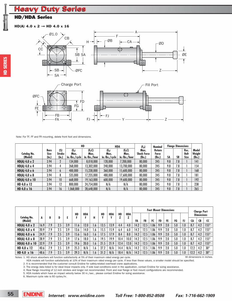
Internet: www.enidine.com Toll Free: 1-800-852-8508 Fax: 1-716-662-190955
Note: For TF, FF and FR mounting, delete front foot and dimensions.
HD
SERIE
S
Charge PortDimensions
Notes: 1. HD shock absorbers will function satisfactorily at 5% of their maximum rated energy per cycle.HDA models will function satisfactorily at 10% of their maximum rated energy per cycle. If less than these values, a smaller model should be specified.
2. It is recommended that the customer consult Enidine for safety-related overhead crane applications.3. The energy data listed is for ideal linear impacts only. If side load conditions exist in the application, contact Enidine for sizing assistance.4. Rear flange mounting of 12 inch strokes and longer not recommended. Front and rear flange or foot mount configurations are recommended.5. HDA models which have an impact velocity below 30 in./sec., please contact Enidine for sizing assistance.6. Maximum cycle rate is 60 cycles/hr.
Foot Mount Dimensions
All dimensions in inches.
HD(A) 4.0 x 2 ➞ HD 4.0 x 16
Heavy Duty SeriesHeavy Duty SeriesHD/HDA Series
ØFC
SASB
SASB
AF
ØDØBH
ØE
Z
Ø1.0CB
CC
CA
FB
FE
Charge Port
FJ Y
Fill Port
ZFA
FGFD
ØFC
FJ
HD HDA HD HDA HD HDAA B D E F F H Y Y Z Z
Flange DimensionsHD HDA
Catalog No.(Model) FA FB FC FD FE FG FJ CA CB CC
HD(A) 4.0 x 2 16.9 7.9 2.5 3.9 11.6 12.0 1.6 13.5 13.9 4.4 4.0 14.2 12.5 1.06 9.9 2.0 5.0 1.0 8.7 4.2 155°HD(A) 4.0 x 4 20.9 7.9 2.5 3.9 13.6 14.0 1.6 15.5 15.9 6.4 6.0 14.2 12.5 1.06 9.9 2.0 5.0 1.0 8.7 4.2 155°HD(A) 4.0 x 6 24.9 7.9 2.5 3.9 15.6 16.0 1.6 17.5 17.9 8.4 8.0 14.2 12.5 1.06 9.9 2.0 5.0 1.0 8.7 4.2 155°HD(A) 4.0 x 8 28.9 7.9 2.5 3.9 17.6 18.0 1.6 19.5 19.9 10.4 10.0 14.2 12.5 1.06 9.9 2.0 5.0 1.0 8.7 4.2 155°HD(A) 4.0 x 10 32.9 7.9 2.5 3.9 19.6 20.0 1.6 21.5 21.9 12.4 12.0 14.2 12.5 1.06 9.9 2.0 5.0 1.0 8.7 4.2 155°HD 4.0 x 12 40.6 7.9 2.5 3.9 25.3 N/A 1.6 27.2 N/A 14.4 N/A 14.2 12.5 1.06 9.9 2.0 5.0 1.0 12.2 4.2 30°HD 4.0 x 16 48.6 7.9 2.5 3.9 29.3 N/A 1.6 31.2 N/A 18.4 N/A 14.2 12.5 1.06 9.9 2.0 5.0 1.0 12.2 4.2 30°
(FP) NominalBore (S) (ET) (ETC) (ET) (ETC) Max. Return Rec. Model
Catalog No. Size Stroke Max. Max. Max. Max. Shock Force Force Bolt Weight (Model) (in.) (in.) in.-lbs./cycle in.-lbs./hour in.-lbs./cycle in.-lbs./hour (lbs.) (lbs.) SA SB Size (lbs.)
HD(A) 4.0 x 2 3.94 2 134,000 8,018,000 120,000 7,200,000 80,000 245 9.8 7.8 1 141HD(A) 4.0 x 4 3.94 4 268,000 13,302,000 240,000 13,700,000 80,000 245 9.8 7.8 1 154HD(A) 4.0 x 6 3.94 6 400,000 15,230,000 360,000 15,600,000 80,000 245 9.8 7.8 1 168HD(A) 4.0 x 8 3.94 8 535,000 17,235,000 480,000 17,600,000 80,000 245 9.8 7.8 1 181HD(A) 4.0 x 10 3.94 10 668,000 19,163,000 600,000 19,600,000 80,000 245 9.8 7.8 1 192HD 4.0 x 12 3.94 12 800,000 24,754,000 N/A N/A 80,000 245 9.8 7.8 1 238HD 4.0 x 16 3.94 16 1,068,000 28,648,000 N/A N/A 80,000 245 9.8 7.8 1 265
ShockCover5-2B 3/31/03 2:30 PM Page 55
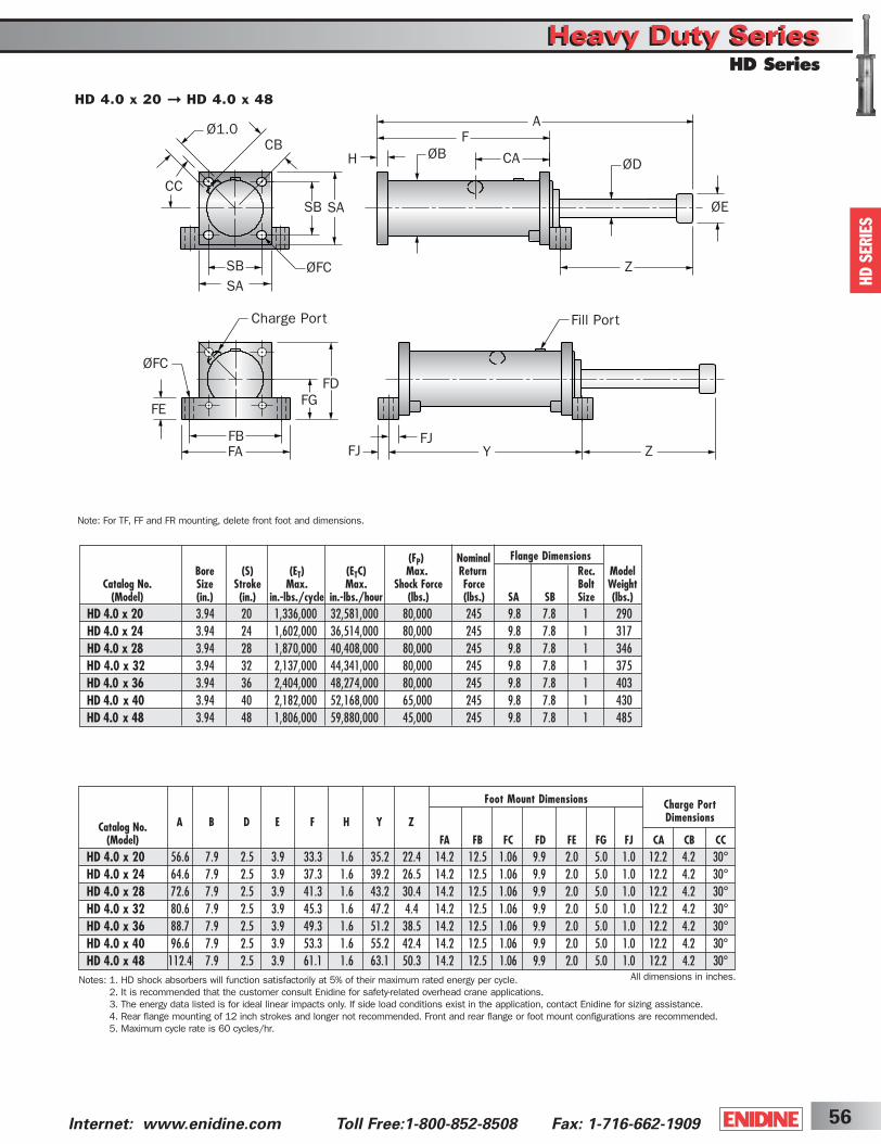
56Internet: www.enidine.com Toll Free:1-800-852-8508 Fax: 1-716-662-1909
HD
SERIE
S
Heavy Duty SeriesHeavy Duty SeriesHD Series
Note: For TF, FF and FR mounting, delete front foot and dimensions.
Charge PortDimensions
Notes: 1. HD shock absorbers will function satisfactorily at 5% of their maximum rated energy per cycle. 2. It is recommended that the customer consult Enidine for safety-related overhead crane applications.3. The energy data listed is for ideal linear impacts only. If side load conditions exist in the application, contact Enidine for sizing assistance.4. Rear flange mounting of 12 inch strokes and longer not recommended. Front and rear flange or foot mount configurations are recommended.5. Maximum cycle rate is 60 cycles/hr.
Foot Mount Dimensions
All dimensions in inches.
HD 4.0 x 20 ➞ HD 4.0 x 48
ØFC
SASB
SASB
AF
ØDØBH
ØE
Z
Ø1.0CB
CC
CA
FB
FE
Charge Port
FJ Y
Fill Port
ZFA
FGFD
ØFC
FJ
A B D E F H Y Z
Flange Dimensions(FP) NominalBore (S) (ET) (ETC) Max. Return Rec. Model
Catalog No. Size Stroke Max. Max. Shock Force Force Bolt Weight (Model) (in.) (in.) in.-lbs./cycle in.-lbs./hour (lbs.) (lbs.) SA SB Size (lbs.)
HD 4.0 x 20 3.94 20 1,336,000 32,581,000 80,000 245 9.8 7.8 1 290HD 4.0 x 24 3.94 24 1,602,000 36,514,000 80,000 245 9.8 7.8 1 317HD 4.0 x 28 3.94 28 1,870,000 40,408,000 80,000 245 9.8 7.8 1 346HD 4.0 x 32 3.94 32 2,137,000 44,341,000 80,000 245 9.8 7.8 1 375HD 4.0 x 36 3.94 36 2,404,000 48,274,000 80,000 245 9.8 7.8 1 403HD 4.0 x 40 3.94 40 2,182,000 52,168,000 65,000 245 9.8 7.8 1 430HD 4.0 x 48 3.94 48 1,806,000 59,880,000 45,000 245 9.8 7.8 1 485
Catalog No.(Model) FA FB FC FD FE FG FJ CA CB CC
HD 4.0 x 20 56.6 7.9 2.5 3.9 33.3 1.6 35.2 22.4 14.2 12.5 1.06 9.9 2.0 5.0 1.0 12.2 4.2 30°HD 4.0 x 24 64.6 7.9 2.5 3.9 37.3 1.6 39.2 26.5 14.2 12.5 1.06 9.9 2.0 5.0 1.0 12.2 4.2 30°HD 4.0 x 28 72.6 7.9 2.5 3.9 41.3 1.6 43.2 30.4 14.2 12.5 1.06 9.9 2.0 5.0 1.0 12.2 4.2 30°HD 4.0 x 32 80.6 7.9 2.5 3.9 45.3 1.6 47.2 4.4 14.2 12.5 1.06 9.9 2.0 5.0 1.0 12.2 4.2 30°HD 4.0 x 36 88.7 7.9 2.5 3.9 49.3 1.6 51.2 38.5 14.2 12.5 1.06 9.9 2.0 5.0 1.0 12.2 4.2 30°HD 4.0 x 40 96.6 7.9 2.5 3.9 53.3 1.6 55.2 42.4 14.2 12.5 1.06 9.9 2.0 5.0 1.0 12.2 4.2 30°HD 4.0 x 48 112.4 7.9 2.5 3.9 61.1 1.6 63.1 50.3 14.2 12.5 1.06 9.9 2.0 5.0 1.0 12.2 4.2 30°
ShockCover5-2B 3/31/03 2:30 PM Page 56

HD
SERIE
S
Heavy Duty SeriesHeavy Duty SeriesHD/HDA Series
Internet: www.enidine.com Toll Free: 1-800-852-8508 Fax: 1-716-662-190957
Note: For TF, FF and FR mounting, delete front foot and dimensions.
Charge PortDimensions
Notes: 1. HD shock absorbers will function satisfactorily at 5% of their maximum rated energy per cycle. HDA models will function satisfactorily at 10% of their maximum rated energy per cycle. If less than these values, a smaller model should be specified.
2. It is recommended that the customer consult Enidine for safety-related overhead crane applications.3. The energy data listed is for ideal linear impacts only. If side load conditions exist in the application, contact Enidine for sizing assistance.4. Rear flange mounting of 12 inch strokes and longer not recommended. Front and rear flange or foot mount configurations are recommended.5. HDA models which have an impact velocity below 30 in./sec., please contact Enidine for sizing assistance.6. Maximum cycle rate is 60 cycles/hr.
Foot Mount Dimensions
All dimensions in inches.
HD(A) 5.0 x 4 ➞ HD(A) 5.0 x 12
FB
FE
Charge Port
FJ Y
Fill Port
ZFA
FGFD
ØFC
FJ
ØFC
SASB
SASB
AF
ØDØBH
ØE
Z
Ø1.0CB
CC
CA
HD HDA HD HDA HD HDAA B D E F F H Y Y Z Z
Flange DimensionsHD HDA (FP) NominalBore (S) (ET) (ETC) (ET) (ETC) Max. Return Rec. Model
Catalog No. Size Stroke Max. Max. Max. Max. Shock Force Force Bolt Weight (Model) (in.) (in.) in.-lbs./cycle in.-lbs./hour in.-lbs./cycle in.-lbs./hour (lbs.) (lbs.) SA SB Size (lbs.)
HD(A) 5.0 x 4 4.92 4 414,000 15,600,000 327,000 16,000,000 124,000 400 10.8 8.7 1 1/4 192HD(A) 5.0 x 6 4.92 6 620,000 17,720,000 500,000 18,000,000 124,000 400 10.8 8.7 1 1/4 207HD(A) 5.0 x 8 4.92 8 828,000 19,841,000 660,000 20,250,000 124,000 400 10.8 8.7 1 1/4 223HD(A) 5.0 x 10 4.92 10 1,036,000 21,921,000 827,000 22,300,000 124,000 400 10.8 8.7 1 1/4 238HD(A) 5.0 x 12 4.92 12 1,239,000 24,042,000 990,000 24,500,000 124,000 400 10.8 8.7 1 1/4 251
Catalog No.(Model) FA FB FC FD FE FG FJ CA CB CC
HD(A) 5.0 x 4 23.3 8.5 3.1 4.9 14.8 15.2 1.6 17.1 17.5 7.4 7.0 15.7 13.4 1.3 10.9 2.4 5.5 1.2 9.1 4.6 25°HD(A) 5.0 x 6 27.3 8.5 3.1 4.9 16.8 17.2 1.6 19.1 19.5 9.4 9.0 15.7 13.4 1.3 10.9 2.4 5.5 1.2 9.1 4.6 25°HD(A) 5.0 x 8 31.3 8.5 3.1 4.9 18.8 19.2 1.6 21.1 21.5 11.4 11.0 15.7 13.4 1.3 10.9 2.4 5.5 1.2 9.1 4.6 25°HD(A) 5.0 x 10 35.3 8.5 3.1 4.9 20.8 21.2 1.6 23.1 23.5 13.4 13.0 15.7 13.4 1.3 10.9 2.4 5.5 1.2 9.1 4.6 25°HD(A) 5.0 x 12 39.3 8.5 3.1 4.9 22.8 23.2 1.6 25.1 25.5 15.4 15.0 15.7 13.4 1.3 10.9 2.4 5.5 1.2 9.1 4.6 25°
ShockCover5-2B 3/31/03 2:30 PM Page 57
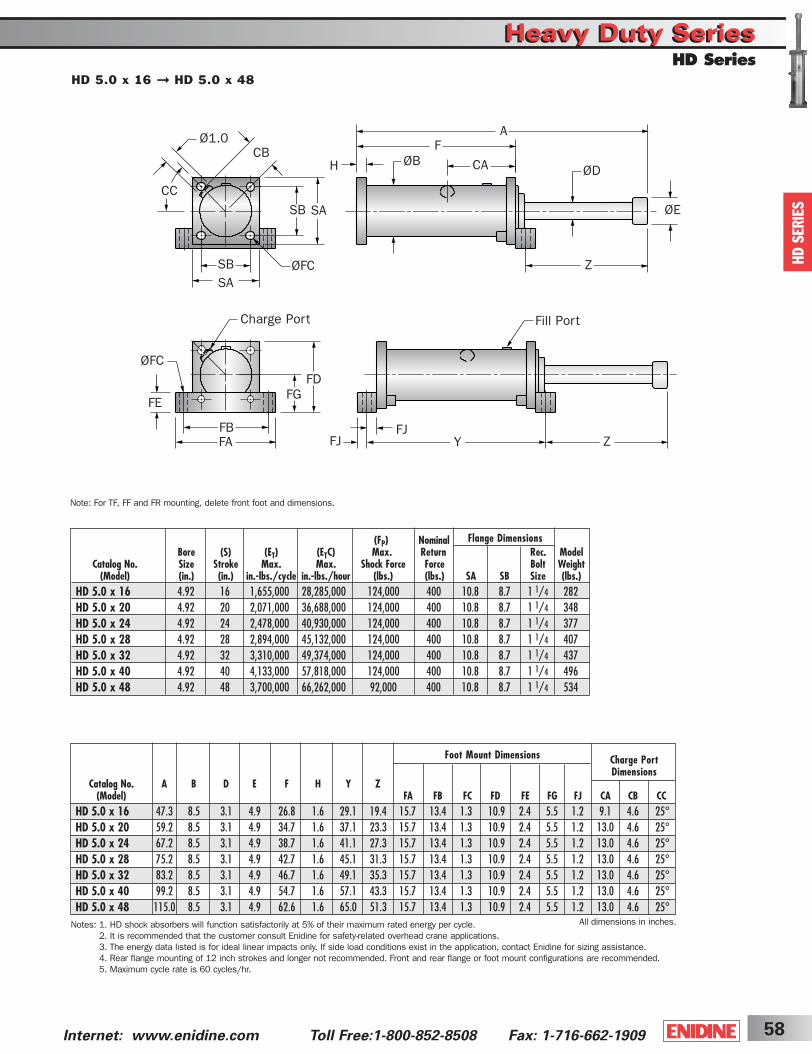
HD
SERIE
S
Heavy Duty SeriesHeavy Duty SeriesHD Series
58Internet: www.enidine.com Toll Free:1-800-852-8508 Fax: 1-716-662-1909
Note: For TF, FF and FR mounting, delete front foot and dimensions.
Charge PortDimensions
Notes: 1. HD shock absorbers will function satisfactorily at 5% of their maximum rated energy per cycle. 2. It is recommended that the customer consult Enidine for safety-related overhead crane applications.3. The energy data listed is for ideal linear impacts only. If side load conditions exist in the application, contact Enidine for sizing assistance.4. Rear flange mounting of 12 inch strokes and longer not recommended. Front and rear flange or foot mount configurations are recommended.5. Maximum cycle rate is 60 cycles/hr.
Foot Mount Dimensions
All dimensions in inches.
HD 5.0 x 16 ➞ HD 5.0 x 48
FB
FE
Charge Port
FJ Y
Fill Port
ZFA
FGFD
ØFC
FJ
ØFC
SASB
SASB
AF
ØDØBH
ØE
Z
Ø1.0CB
CC
CA
Flange Dimensions(FP) NominalBore (S) (ET) (ETC) Max. Return Rec. Model
Catalog No. Size Stroke Max. Max. Shock Force Force Bolt Weight (Model) (in.) (in.) in.-lbs./cycle in.-lbs./hour (lbs.) (lbs.) SA SB Size (lbs.)
HD 5.0 x 16 4.92 16 1,655,000 28,285,000 124,000 400 10.8 8.7 1 1/4 282HD 5.0 x 20 4.92 20 2,071,000 36,688,000 124,000 400 10.8 8.7 1 1/4 348HD 5.0 x 24 4.92 24 2,478,000 40,930,000 124,000 400 10.8 8.7 1 1/4 377HD 5.0 x 28 4.92 28 2,894,000 45,132,000 124,000 400 10.8 8.7 1 1/4 407HD 5.0 x 32 4.92 32 3,310,000 49,374,000 124,000 400 10.8 8.7 1 1/4 437HD 5.0 x 40 4.92 40 4,133,000 57,818,000 124,000 400 10.8 8.7 1 1/4 496HD 5.0 x 48 4.92 48 3,700,000 66,262,000 92,000 400 10.8 8.7 1 1/4 534
Catalog No. A B D E F H Y Z(Model) FA FB FC FD FE FG FJ CA CB CC
HD 5.0 x 16 47.3 8.5 3.1 4.9 26.8 1.6 29.1 19.4 15.7 13.4 1.3 10.9 2.4 5.5 1.2 9.1 4.6 25°HD 5.0 x 20 59.2 8.5 3.1 4.9 34.7 1.6 37.1 23.3 15.7 13.4 1.3 10.9 2.4 5.5 1.2 13.0 4.6 25°HD 5.0 x 24 67.2 8.5 3.1 4.9 38.7 1.6 41.1 27.3 15.7 13.4 1.3 10.9 2.4 5.5 1.2 13.0 4.6 25°HD 5.0 x 28 75.2 8.5 3.1 4.9 42.7 1.6 45.1 31.3 15.7 13.4 1.3 10.9 2.4 5.5 1.2 13.0 4.6 25°HD 5.0 x 32 83.2 8.5 3.1 4.9 46.7 1.6 49.1 35.3 15.7 13.4 1.3 10.9 2.4 5.5 1.2 13.0 4.6 25°HD 5.0 x 40 99.2 8.5 3.1 4.9 54.7 1.6 57.1 43.3 15.7 13.4 1.3 10.9 2.4 5.5 1.2 13.0 4.6 25°HD 5.0 x 48 115.0 8.5 3.1 4.9 62.6 1.6 65.0 51.3 15.7 13.4 1.3 10.9 2.4 5.5 1.2 13.0 4.6 25°
ShockCover5-2B 3/31/03 2:30 PM Page 58
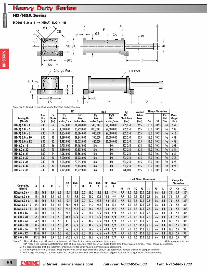
Internet: www.enidine.com Toll Free: 1-800-852-8508 Fax: 1-716-662-190959
HD
SERIE
S
Charge PortDimensions
Foot Mount Dimensions
All dimensions in inches.
HD(A) 6.0 x 4 ➞ HD(A) 6.0 x 48
Heavy Duty SeriesHeavy Duty SeriesHD/HDA Series
ØFC
SASB
SASB
AF
ØDØBH
ØE
Z
Ø1.0CB
CC
CA
FB
FE
Charge Port
FJ Y
Fill Port
ZFA
FGFD
ØFC
FJ
Note: For TF, FF and FR mounting, delete front foot and dimensions.
Notes: 1. HD shock absorbers will function satisfactorily at 5% of their maximum rated energy per cycle.HDA models will function satisfactorily at 10% of their maximum rated energy per cycle. If less than these values, a smaller model should be specified.
2. It is recommended that the customer consult Enidine for safety-related overhead crane applications.3. The energy data listed is for ideal linear impacts only. If side load conditions exist in the application, contact Enidine for sizing assistance.4. Rear flange mounting of 12 inch strokes and longer not recommended. Front and rear flange or foot mount configurations are recommended.
HD HDA HD HDA HD HDAA B D E F F H Y Y Z Z
Flange DimensionsHD HDA
Catalog No.(Model) FA FB FC FD FE FG FJ CA CB CC
HD(A) 6.0 x 4 25.1 10.8 3.9 6.3 15.4 15.8 2.0 18.2 18.6 8.3 7.9 17.7 15.0 1.6 13.1 2.8 6.6 1.4 7.8 5.7 30°HD(A) 6.0 x 6 29.1 10.8 3.9 6.3 17.4 17.8 2.0 20.2 20.6 10.3 9.9 17.7 15.0 1.6 13.1 2.8 6.6 1.4 7.8 5.7 30°HD(A) 6.0 x 8 33.1 10.8 3.9 6.3 19.4 19.8 2.0 22.2 22.6 12.3 11.9 17.7 15.0 1.6 13.1 2.8 6.6 1.4 7.8 5.7 30°HD(A) 6.0 x 10 37.1 10.8 3.9 6.3 21.4 21.8 2.0 24.2 24.6 14.3 13.9 17.7 15.0 1.6 13.1 2.8 6.6 1.4 7.8 5.7 30°HD(A) 6.0 x 12 41.1 10.8 3.9 6.3 23.4 23.8 2.0 26.2 26.6 16.3 15.9 17.7 15.0 1.6 13.1 2.8 6.6 1.4 7.8 5.7 30°HD 6.0 x 16 49.1 10.8 3.9 6.3 27.4 N/A 2.0 30.2 N/A 20.3 N/A 17.7 15.0 1.6 13.1 2.8 6.6 1.4 7.8 5.7 30°HD 6.0 x 20 57.1 10.8 3.9 6.3 31.4 N/A 2.0 34.2 N/A 24.3 N/A 17.7 15.0 1.6 13.1 2.8 6.6 1.4 7.8 5.7 30°HD 6.0 x 24 69.7 10.8 3.9 6.3 40.0 N/A 2.0 42.7 N/A 28.4 N/A 17.7 15.0 1.6 13.1 2.8 6.6 1.4 12.3 5.7 30°HD 6.0 x 30 81.6 10.8 3.9 6.3 46.0 N/A 2.0 48.7 N/A 34.3 N/A 17.7 15.0 1.6 13.1 2.8 6.6 1.4 12.3 5.7 30°HD 6.0 x 36 93.7 10.8 3.9 6.3 52.0 N/A 2.0 54.7 N/A 40.4 N/A 17.7 15.0 1.6 13.1 2.8 6.6 1.4 12.3 5.7 30°HD 6.0 x 42 105.6 10.8 3.9 6.3 58.0 N/A 2.0 60.7 N/A 46.3 N/A 17.7 15.0 1.6 13.1 2.8 6.6 1.4 12.3 5.7 30°HD 6.0 x 48 117.7 10.8 3.9 6.3 64.0 N/A 2.0 66.7 N/A 52.4 N/A 17.7 15.0 1.6 13.1 2.8 6.6 1.4 12.3 5.7 30°
(FP) NominalBore (S) (ET) (ETC) (ET) (ETC) Max. Return Rec. Model
Catalog No. Size Stroke Max. Max. Max. Max. Shock Force Force Bolt Weight (Model) (in.) (in.) in.-lbs./cycle in.-lbs./hour in.-lbs./cycle in.-lbs./hour (lbs.) (lbs.) SA SB Size (lbs.)
HD(A) 6.0 x 4 6.30 4 677,000 21,280,000 540,000 22,000,000 202,250 625 13.0 10.2 1 1/2 362HD(A) 6.0 x 6 6.30 6 1,010,000 23,933,000 810,000 24,500,000 202,250 625 13.0 10.2 1 1/2 386HD(A) 6.0 x 8 6.30 8 1,354,000 26,586,000 1,080,000 27,000,000 202,250 625 13.0 10.2 1 1/2 410HD(A) 6.0 x 10 6.30 10 1,690,000 29,345,000 1,350,000 30,000,000 202,250 625 13.0 10.2 1 1/2 432HD(A) 6.0 x 12 6.30 12 1,982,000 32,052,000 1,620,000 33,000,000 202,250 625 13.0 10.2 1 1/2 456HD 6.0 x 16 6.30 16 2,708,000 37,465,000 N/A N/A 202,250 625 13.0 10.2 1 1/2 503HD 6.0 x 20 6.30 20 3,380,000 42,877,000 N/A N/A 202,250 625 13.0 10.2 1 1/2 551HD 6.0 x 24 6.30 24 4,062,000 53,862,000 N/A N/A 202,250 625 13.0 10.2 1 1/2 681HD 6.0 x 30 6.30 30 5,070,000 61,928,000 N/A N/A 202,250 625 13.0 10.2 1 1/2 752HD 6.0 x 36 6.30 36 6,093,000 70,047,000 N/A N/A 202,250 625 13.0 10.2 1 1/2 822HD 6.0 X 42 6.30 42 7,106,000 78,113,000 N/A N/A 202,250 625 13.0 10.2 1 1/2 893HD 6.0 x 48 6.30 48 7,125,000 86,232,000 N/A N/A 178,000 625 13.0 10.2 1 1/2 966
ShockCover5-2B 3/31/03 2:30 PM Page 59
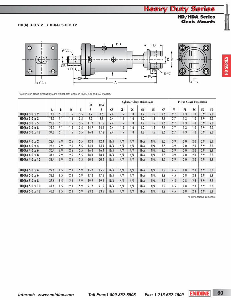
60Internet: www.enidine.com Toll Free:1-800-852-8508 Fax: 1-716-662-1909
HD
SERIE
S
Note: Piston clevis dimensions are typical both ends on HD(A) 4.0 and 5.0 models.
ØFC
A
FB
FA
CA
FD
F FE
ØCC
ØB
CB
D
CD CE
CF
E
Cylinder Clevis Dimensions Piston Clevis Dimensions
HD(A) 3.0 x 2 ➞ HD(A) 5.0 x 12
Heavy Duty SeriesHeavy Duty SeriesHD/HDA SeriesClevis Mounts
HD HDAA B D E F F CA CB CC CD CE CF FA FB FC FD FE
HD(A) 3.0 x 2 17.0 5.1 1.5 3.5 8.2 8.6 2.4 1.5 1.0 1.2 1.5 2.6 2.7 1.3 1.0 3.9 2.0HD(A) 3.0 x 3 19.0 5.1 1.5 3.5 9.2 9.6 2.4 1.5 1.0 1.2 1.5 2.6 2.7 1.3 1.0 3.9 2.0HD(A) 3.0 x 5 23.0 5.1 1.5 3.5 11.2 11.6 2.4 1.5 1.0 1.2 1.5 2.6 2.7 1.3 1.0 3.9 2.0HD(A) 3.0 x 8 29.0 5.1 1.5 3.5 14.2 14.6 2.4 1.5 1.0 1.2 1.5 2.6 2.7 1.3 1.0 3.9 2.0HD(A) 3.0 x 12 37.0 5.1 1.5 3.5 16.8 17.2 2.4 1.5 1.0 1.2 1.5 2.6 2.7 1.3 1.0 3.9 2.0
HD(A) 4.0 x 2 22.4 7.9 2.6 5.5 12.0 12.4 N/A N/A N/A N/A N/A 3.5 3.9 2.0 2.0 5.9 3.9HD(A) 4.0 x 4 26.4 7.9 2.6 5.5 14.0 14.4 N/A N/A N/A N/A N/A 3.5 3.9 2.0 2.0 5.9 3.9HD(A) 4.0 x 6 30.4 7.9 2.6 5.5 16.0 16.4 N/A N/A N/A N/A N/A 3.5 3.9 2.0 2.0 5.9 3.9HD(A) 4.0 x 8 34.4 7.9 2.6 5.5 18.0 18.4 N/A N/A N/A N/A N/A 3.5 3.9 2.0 2.0 5.9 3.9HD(A) 4.0 x 10 38.4 7.9 2.6 5.5 20.0 20.4 N/A N/A N/A N/A N/A 3.5 3.9 2.0 2.0 5.9 3.9
HD(A) 5.0 x 4 29.6 8.5 2.8 5.9 15.2 15.6 N/A N/A N/A N/A N/A 3.9 4.5 2.8 2.3 6.9 3.9
HD(A) 5.0 x 6 33.6 8.5 2.8 5.9 17.2 17.6 N/A N/A N/A N/A N/A 3.9 4.5 2.8 2.3 6.9 3.9
HD(A) 5.0 x 8 37.6 8.5 2.8 5.9 19.2 19.6 N/A N/A N/A N/A N/A 3.9 4.5 2.8 2.3 6.9 3.9
HD(A) 5.0 x 10 41.6 8.5 2.8 5.9 21.2 21.6 N/A N/A N/A N/A N/A 3.9 4.5 2.8 2.3 6.9 3.9
HD(A) 5.0 x 12 45.6 8.5 2.8 5.9 23.2 23.6 N/A N/A N/A N/A N/A 3.9 4.5 2.8 2.3 6.9 3.9
All dimensions in inches.
ShockCover5-2B 3/31/03 2:30 PM Page 60

Internet: www.enidine.com Toll Free: 1-800-852-8508 Fax: 1-716-662-190961
After properly sizing an HDA shock absorber, the useablerange of adjustment settings can be determined:1. Locate the intersection point of the application's impact
velocity and the HDA model graph line.2. The intersection is the maximum adjustment setting to be
used. Adjustments exceeding this setting could overloadthe shock absorber.
3. The useable adjustment setting range is from setting 1 tothe MAXIMUM adjustment setting as determined in step 2.
EXAMPLE: HDA Series1. Impact Velocity: 80 in./sec.2. Intersection Point: Adjustment Setting 33. Useable Adjustment Setting Range: 1 to 3
HD
A
Damping Force Position 1 provides minimum damping force. Position 5 provides maximum damping force.
Useable Adjustment Setting Range
Locking Cam Screw
• Magnetic proximity sensor indicates complete piston rod return with 10-foot long cable.
• If complete piston rod does not return the circuit remains open. This can be used to trigger a system shut-off.
• Contact Enidine for other available sensor types.
Adjustment is accomplished by turning the adjustment screw. Once the desired setting has been reached, lock in place by tighteningthe locking cam screw.
Adjustment Screw
Piston Rod ReturnSensor
Sensor Specifications
• Voltage 10 - 30V• Load Current ≤ 200 µA• Leakage Current ≤ 80 µA• Load Capacitance ≤ 1.0 µF • Ambient Temperature: -15° to 160°F
HD
SERIE
S
Optional Piston Rod Return Sensor
Heavy Duty SeriesHeavy Duty SeriesHD/HDA Series
br +
–
swbl
ShockCover5-2B 3/31/03 2:30 PM Page 61
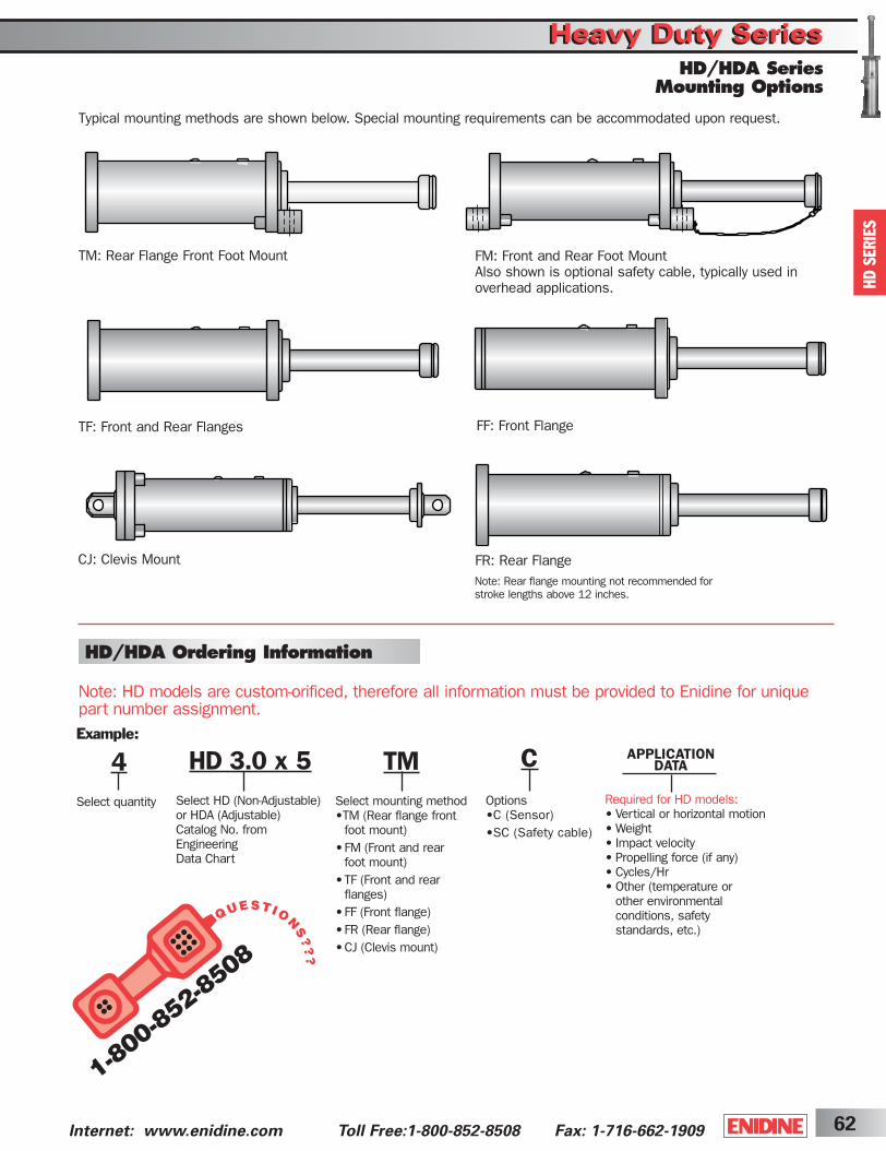
62Internet: www.enidine.com Toll Free:1-800-852-8508 Fax: 1-716-662-1909
HD 3.0 x 5Select HD (Non-Adjustable)or HDA (Adjustable) Catalog No. from EngineeringData Chart
Example:
4Select quantity
TMSelect mounting method •TM (Rear flange front
foot mount)•FM (Front and rear
foot mount)•TF (Front and rear
flanges)•FF (Front flange)•FR (Rear flange)•CJ (Clevis mount)
APPLICATION DATA
Note: HD models are custom-orificed, therefore all information must be provided to Enidine for uniquepart number assignment.
Typical mounting methods are shown below. Special mounting requirements can be accommodated upon request.
TM: Rear Flange Front Foot Mount
TF: Front and Rear Flanges
FM: Front and Rear Foot MountAlso shown is optional safety cable, typically used in overhead applications.
FF: Front Flange
CJ: Clevis Mount
Required for HD models:• Vertical or horizontal motion• Weight• Impact velocity• Propelling force (if any)• Cycles/Hr• Other (temperature or
other environmental conditions, safety standards, etc.)
FR: Rear FlangeNote: Rear flange mounting not recommended forstroke lengths above 12 inches.
COptions •C (Sensor)•SC (Safety cable)
HD
SERIE
S
HD/HDA Ordering Information
Heavy Duty SeriesHeavy Duty SeriesHD/HDA Series
Mounting Options
ShockCover5-2B 3/31/03 2:30 PM Page 62
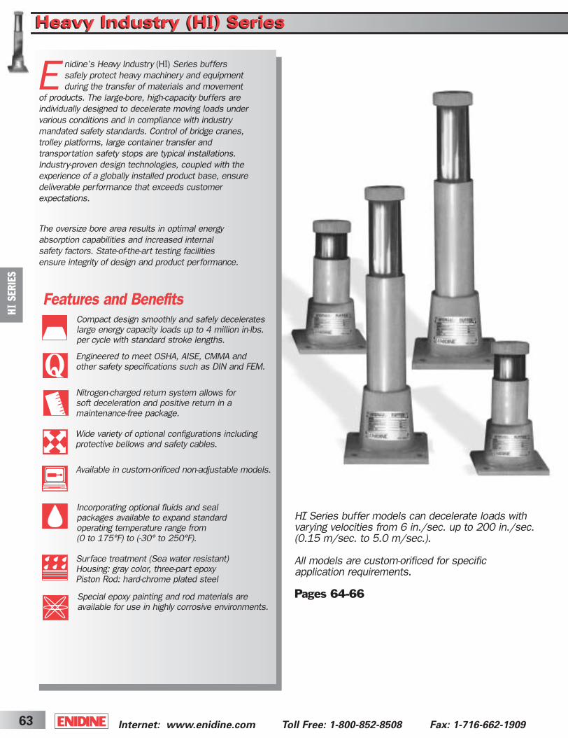
E nidine’s Heavy Industry (HI) Series buffers safely protect heavy machinery and equipment during the transfer of materials and movement
of products. The large-bore, high-capacity buffers are individually designed to decelerate moving loads under various conditions and in compliance with industry mandated safety standards. Control of bridge cranes, trolley platforms, large container transfer and transportation safety stops are typical installations. Industry-proven design technologies, coupled with the experience of a globally installed product base, ensure deliverable performance that exceeds customer expectations.
The oversize bore area results in optimal energy absorption capabilities and increased internal safety factors. State-of-the-art testing facilities ensure integrity of design and product performance.
Internet: www.enidine.com Toll Free: 1-800-852-8508 Fax: 1-716-662-190963
HI
SER
IES
Heavy Industry (HI) SeriesHeavy Industry (HI) Series
Features and BenefitsCompact design smoothly and safely decelerateslarge energy capacity loads up to 4 million in-lbs. per cycle with standard stroke lengths.
Engineered to meet OSHA, AISE, CMMA and other safety specifications such as DIN and FEM.
Nitrogen-charged return system allows for soft deceleration and positive return in a maintenance-free package.
Wide variety of optional configurations including protective bellows and safety cables.
Available in custom-orificed non-adjustable models.
Special epoxy painting and rod materials are available for use in highly corrosive environments.
Incorporating optional fluids and seal packages available to expand standard operating temperature range from (0 to 175°F) to (-30° to 250°F).
Surface treatment (Sea water resistant) Housing: gray color, three-part epoxyPiston Rod: hard-chrome plated steel
H Series buffer models can decelerate loads with varying velocities from 6 in./sec. up to 200 in./sec.(0.15 m/sec. to 5.0 m/sec.).
All models are custom-orificed for specific application requirements.
Pages 64-66
ShockCover5-2B 3/31/03 2:30 PM Page 63

64Internet: www.enidine.com Toll Free:1-800-852-8508 Fax: 1-716-662-1909
HI
SER
IES
Heavy Industry (HI) SeriesHeavy Industry (HI) Series
Enidine’s Heavy Industry Series (HI) buffers safely protectheavy machinery and equipment during the transfer of materials and movement of products. The large-bore,
high-capacity buffers are individually designed to decelerate moving loads under various conditions and in compliance withindustry mandated safety standards. Control of bridge cranes, trolley platforms, large container transfer and transportation safetystops are typical installation examples. Industry-proven design technologies, coupled with the experience of a globally installedproduct base, ensure deliverable performance that exceeds customer expectations.
Prior to HI Series buffer manufacture, computer-simulated response curves are generated to model actual conditions, verify product performance, confirm damping characteristics and generate unique custom-orificed designs that accommodatemulti-condition or specific damping requirements.
Characteristics of the HI Series include a nitrogen-charged returnsystem that allows for soft deceleration and positive return in a maintenance-free package. The oversize bore area results in optimal energy absorption capabilities and increased internal safety factors. State-of-the-art testing facilities ensure integrity of design and product performance.
Design OverviewThe HI Series buffer design incorporates a proven damping system of multiple orifice patterns drilled down the shock tubelength, for precise deceleration profiles, coupled with a nitrogenreturn system for controlled extension of the piston rod to its original position.
During piston movement, oil is forced through the orifice patterninto the oil reservoir chamber. This controlled movement of a piston head by decreasing the orifice area results in precise decay of impact velocity and safe deceleration of the moving load.The oil volume evacuated from the high pressure chamber movesthe separating piston, compensating for the oil differential withinthe unit.
Extension of the piston rod for the next impact is accomplished by the force created from the compressed nitrogen chamber, which acts as both an oil volume compensator and return force mechanism. The pressure created pushes the fluid back into the oil chamber and creates a force to reposition the piston rod to the fully extended position, ready for the next impact sequence. The nitrogen return system enables the HI Series to be designed for the maximum energy absorption within the smallest envelope size.
Orifice
Oil Reservoir
SeparatingPiston
Piston Cap
Piston RodCylinder
Oil Chamber
Heavy Industry (H ) Series Buffers
H Series
ShockCover5-2B 3/31/03 2:30 PM Page 64

H Series
Internet: www.enidine.com Toll Free: 1-800-852-8508 Fax: 1-716-662-190965
Return Force
All dimensions in inches.
ØB ØB
Z
SHH
SBSA
S
4-ØFC
ØE ØE
A1 A2FR (Flange Rear) Mounting Flange FF (Flange Front)
Heavy Industry (HI) SeriesHeavy Industry (HI) Series
HI 100 x 50 ➞ HI 120 x 1000
HI
SER
IES
Max.S Max. Shock Rec.
Model Stroke Energy/cycle Force Extension Compression Weight BOLT(in.) (in.-lbs.) (lbs.) (lbs.) (lbs.) (lbs.) A1 A2 Z H ØB SA SB ØFC SIZE ØE
HI 100 x 50 2 88,500 56,200 370 4,050 36 11.9 11.8 6.9 0.8 3.93 5.90 4.72 0.70 5/8 3.89HI 100 x 100 3.9 177,000 56,200 370 4,050 49 18.9 18.6 9.7 0.8 3.93 5.90 4.72 0.70 5/8 3.89HI 100 x 150 5.9 265,500 56,200 370 4,050 24.3 24.1 11.8 0.8 0.8 3.93 5.90 4.72 0.70 5/8 3.89HI 100 x 200 7.9 354,000 56,200 370 4,050 71 29.8 29.5 15.4 0.8 3.93 5.90 4.72 0.70 5/8 3.89HI 100 x 500 19.7 831,900 52,800 370 4,050 115 N/A 63.6 35.0 0.8 3.93 5.90 4.72 0.70 5/8 3.89HI 100 x 600 23.6 991,200 51,700 370 4,050 128 N/A 74.3 40.9 0.8 3.93 5.90 4.72 0.70 5/8 3.89HI 100 x 800 31.5 1,168,200 46,085 370 4,050 152 N/A 95.5 52.9 0.8 3.93 5.90 4.72 0.70 5/8 3.89HI 120 x 100 3.9 283,200 89,920 630 11,250 75 18.5 18.4 10.6 0.8 4.72 8.66 6.69 1.03 1 4.68HI 120 x 150 5.9 424,800 89,920 630 11,250 86 23.5 23.3 13.0 0.8 4.72 8.66 6.69 1.03 1 4.68HI 120 x 200 7.9 566,400 89,920 630 11,250 95 28.5 28.3 15.4 0.8 4.72 8.66 6.69 1.03 1 4.68HI 120 x 300 11.8 831,900 89,920 630 11,250 117 38.3 38.1 20.5 0.8 4.72 8.66 6.69 1.03 1 4.68HI 120 x 400 15.7 1,106,300 89,920 630 11,250 192 48.2 48.1 26.8 1.0 4.72 8.66 6.69 1.03 1 4.68HI 120 x 600 23.6 1,663,900 89,920 630 11,250 232 N/A 67.9 36.0 1.0 4.72 8.66 6.69 1.03 1 4.68HI 120 x 800 31.5 1,991,250 78,630 630 11,250 242 N/A 91.8 50.8 1.0 4.72 8.66 6.69 1.03 1 4.68HI 120 x 1000 39.4 2,301,000 73,060 630 11,250 255 N/A 111.6 61.4 1.0 4.72 8.66 6.69 1.03 1 4.68
ShockCover5-2B 3/31/03 2:30 PM Page 65
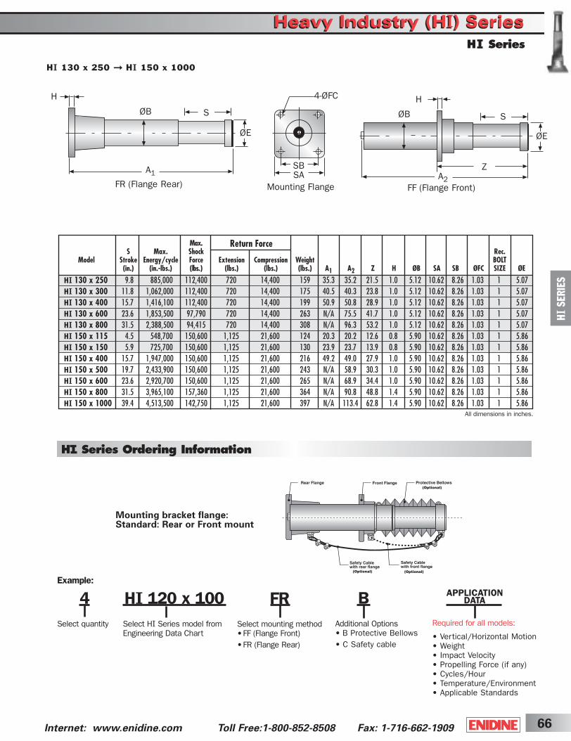
66Internet: www.enidine.com Toll Free:1-800-852-8508 Fax: 1-716-662-1909
Mounting bracket flange: Standard: Rear or Front mount
Return Force
HI 120 x 100Select HI Series model from Engineering Data Chart
Example:
4Select quantity
FRSelect mounting method •FF (Flange Front)•FR (Flange Rear)
APPLICATION DATA
Required for all models:
• Vertical/Horizontal Motion• Weight• Impact Velocity• Propelling Force (if any)• Cycles/Hour• Temperature/Environment• Applicable Standards
BAdditional Options • B Protective Bellows• C Safety cable
H Series Ordering Information
All dimensions in inches.
ØB ØB
Z
SHH
SBSA
S
4-ØFC
ØE ØE
A1 A2FR (Flange Rear) Mounting Flange FF (Flange Front)
Max.S Max. Shock Rec.
Model Stroke Energy/cycle Force Extension Compression Weight BOLT(in.) (in.-lbs.) (lbs.) (lbs.) (lbs.) (lbs.) A1 A2 Z H ØB SA SB ØFC SIZE ØE
HI 130 x 250 9.8 885,000 112,400 720 14,400 159 35.3 35.2 21.5 1.0 5.12 10.62 8.26 1.03 1 5.07HI 130 x 300 11.8 1,062,000 112,400 720 14,400 175 40.5 40.3 23.8 1.0 5.12 10.62 8.26 1.03 1 5.07HI 130 x 400 15.7 1,416,100 112,400 720 14,400 199 50.9 50.8 28.9 1.0 5.12 10.62 8.26 1.03 1 5.07HI 130 x 600 23.6 1,853,500 97,790 720 14,400 263 N/A 75.5 41.7 1.0 5.12 10.62 8.26 1.03 1 5.07HI 130 x 800 31.5 2,388,500 94,415 720 14,400 308 N/A 96.3 53.2 1.0 5.12 10.62 8.26 1.03 1 5.07HI 150 x 115 4.5 548,700 150,600 1,125 21,600 124 20.3 20.2 12.6 0.8 5.90 10.62 8.26 1.03 1 5.86HI 150 x 150 5.9 725,700 150,600 1,125 21,600 130 23.9 23.7 13.9 0.8 5.90 10.62 8.26 1.03 1 5.86HI 150 x 400 15.7 1,947,000 150,600 1,125 21,600 216 49.2 49.0 27.9 1.0 5.90 10.62 8.26 1.03 1 5.86HI 150 x 500 19.7 2,433,900 150,600 1,125 21,600 243 N/A 58.9 30.3 1.0 5.90 10.62 8.26 1.03 1 5.86HI 150 x 600 23.6 2,920,700 150,600 1,125 21,600 265 N/A 68.9 34.4 1.0 5.90 10.62 8.26 1.03 1 5.86HI 150 x 800 31.5 3,965,100 157,360 1,125 21,600 364 N/A 90.8 48.8 1.4 5.90 10.62 8.26 1.03 1 5.86HI 150 x 1000 39.4 4,513,500 142,750 1,125 21,600 397 N/A 113.4 62.8 1.4 5.90 10.62 8.26 1.03 1 5.86
Heavy Industry (HI) SeriesHeavy Industry (HI) SeriesH Series
HI 130 x 250 ➞ HI 150 x 1000
HI
SER
IES
ShockCover5-2B 3/31/03 2:30 PM Page 66
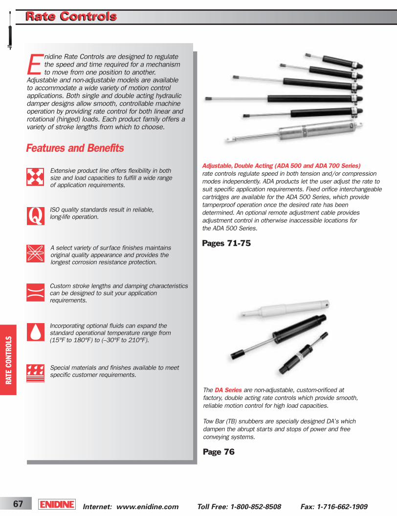
Rate ControlsRate Controls
Internet: www.enidine.com Toll Free: 1-800-852-8508 Fax: 1-716-662-190967
Features and Benefits
Enidine Rate Controls are designed to regulatethe speed and time required for a mechanismto move from one position to another.
Adjustable and non-adjustable models are available to accommodate a wide variety of motion controlapplications. Both single and double acting hydraulicdamper designs allow smooth, controllable machineoperation by providing rate control for both linear androtational (hinged) loads. Each product family offers avariety of stroke lengths from which to choose.
The DA Series are non-adjustable, custom-orificed at factory, double acting rate controls which provide smooth,reliable motion control for high load capacities.
Tow Bar (TB) snubbers are specially designed DA’s whichdampen the abrupt starts and stops of power and free conveying systems.
Page 76
Adjustable,Double Acting (ADA500 and ADA700 Series)rate controls regulate speed in both tension and/or compressionmodes independently. ADA products let the user adjust the rate to suit specific application requirements. Fixed orifice interchangeablecartridges are available for the ADA 500 Series, which provide tamperproof operation once the desired rate has been determined. An optional remote adjustment cable provides adjustment control in otherwise inaccessible locations for the ADA 500 Series.
Pages 71-75
Extensive product line offers flexibility in both size and load capacities to fulfill a wide range of application requirements.
ISO quality standards result in reliable, long-life operation.
Custom stroke lengths and damping characteristicscan be designed to suit your application requirements.
Incorporating optional fluids can expand the standard operational temperature range from (15°F to 180°F) to (–30°F to 210°F).
Special materials and finishes available to meet specific customer requirements.
RATE C
ON
TR
OLS
A select variety of surface finishes maintainsoriginal quality appearance and provides thelongest corrosion resistance protection.
ShockCover5-2B 3/31/03 2:30 PM Page 67
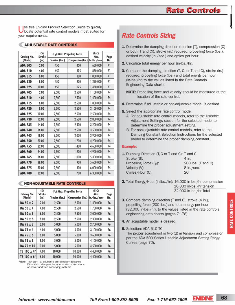
Rate ControlsRate Controls
68Internet: www.enidine.com Toll Free:1-800-852-8508 Fax: 1-716-662-1909
Rate Controls Sizing1. Determine the damping direction (tension [T], compression [C]
or both [T and C]), stroke (in.) required, propelling force (lbs.),desired velocity (in./sec.) and cycles per hour.
2. Calculate total energy per hour (in-lbs./hr).
3. Compare the damping direction (T, C, or T and C), stroke (in.)required, propelling force (lbs.) and total energy per hour (in-lbs./hr) to the values listed in the Rate ControlsEngineering Data charts.
NOTE: Propelling force and velocity should be measured at thelocation of the rate control.
4. Determine if adjustable or non-adjustable model is desired.
5. Select the appropriate rate control model.A. For adjustable rate control models, refer to the Useable
Adjustment Settings section for the selected model to determine the proper adjustment setting.
B. For non-adjustable rate control models, refer to the Damping Constant Selection Instructions for the selected model to determine the proper damping constant.
Example:
1. Damping Direction (T,C or T and C): T and CStroke (S): 4 in.Propelling Force (FD): 200 lbs. (T and C)Velocity (V): 8 in./sec.Cycles/Hour (C): 20
2. Total Energy/Hour (in-lbs./hr): 16,000 in-lbs./hr compression16,000 in-lbs./hr tension32,000 in-lbs./hr Total
3. Compare damping direction (T and C), stroke (4 in.), propelling force (200 lbs.) and total energy per hour (32,000 in-lbs./hr), to the values listed in the rate controls engineering data charts (pages 71-76).
4. An adjustable model is desired.
5. Selection: ADA 510 TCThe proper adjustment is two (2) in tension and compression per the ADA 500 Series Useable Adjustment Setting RangeCurves (page 72).
ADJUSTABLE RATE CONTROLS
(S) (ETC)Catalog No. Stroke
(FD) Max. Propelling ForceMax. Page
(Model) (in.) Tension (lbs.) Compression (lbs.) in.-lbs./hour No.
ADA 505 2.00 450 450 650,000 71
ADA 510 4.00 450 375 850,000 71
ADA 515 6.00 450 300 1,050,000 71
ADA 520 8.00 450 200 1,250,000 71
ADA 525 10.00 450 125 1,450,000 71
ADA 705 2.00 2,500 2,500 1,100,000 74
ADA 710 4.00 2,500 2,500 1,400,000 74
ADA 715 6.00 2,500 2,500 1,800,000 74
ADA 720 8.00 2,500 2,500 2,100,000 74
ADA 725 10.00 2,500 2,500 2,500,000 74
ADA 730 12.00 2,500 2,500 2,800,000 74
ADA 735 14.00 2,500 2,500 3,200,000 74
ADA 740 16.00 2,500 2,500 3,500,000 74
ADA 745 18.00 2,500 2,000 3,900,000 74
ADA 750 20.00 2,500 1,700 4,200,000 74
ADA 755 22.00 2,500 1,400 4,600,000 74
ADA 760 24.00 2,500 1,200 4,900,000 74
ADA 765 26.00 2,500 1,000 5,300,000 74
ADA 770 28.00 2,500 900 5,600,000 74
ADA 775 30.00 2,500 800 6,000,000 74
ADA 780 32.00 2,500 700 6,300,000 74
NON-ADJUSTABLE RATE CONTROLS
*Note: Tow Bar (TB) snubbers are specially designed DA's which dampen the abrupt starts and stops of power and free conveying systems.
(S) (ETC)Catalog No. Stroke
(FD) Max. Propelling ForceMax. Page
(Model) (in.) Tension (lbs.) Compression (lbs.) in.-lbs./hour No.
DA 50 x 2 2.00 2,500 2,500 1,400,000 76
DA 50 x 4 4.00 2,500 2,500 1,700,000 76
DA 50 x 6 6.00 2,500 2,500 2,000,000 76
DA 50 x 8 8.00 2,500 2,500 2,300,000 76
DA 75 x 2 2.00 5,000 5,000 2,700,000 76
DA 75 x 4 4.00 5,000 5,000 3,100,000 76
DA 75 x 6 6.00 5,000 5,000 3,600,000 76
DA 75 x 8 8.00 5,000 5,000 4,100,000 76
DA 75 x 10 10.00 5,000 5,000 4,500,000 76
TB 100 x 4* 4.00 10,000 10,000 4,400,000 76
TB 100 x 6* 6.00 10,000 10,000 4,400,000 76
Use this Enidine Product Selection Guide to quickly locate potential rate control models most suited for
your requirements.
RATE C
ON
TR
OLS
ShockCover5-2B 3/31/03 2:30 PM Page 68

Internet: www.enidine.com Toll Free: 1-800-852-8508 Fax: 1-716-662-190969
Enidine Rate Controls are used to regulate the speed ortime required for a mechanism to move from one position to another. They use proven technology to
enhance performance in a variety of product applications.Rate controls are typically used to control pneumatic cylinders, linear slides, lids, and other moving mechanisms.
The advantages of using rate controls include:
1. Longer Machine Life – The use of rate controls significantly reduces shock and vibration to machinerycaused by uncontrolled machine operation. This furtherreduces machinery damage, downtime and maintenancecosts, while increasing machine life.
2. Improved Production Quality – Harmful effects of uncontrolled motion, such as noise, vibration and damagingimpacts, are moderated or eliminated so that production quality is improved.
3. Safer Machinery Operation – Rate controls protectmachinery and equipment operators by offering predictable,reliable and controlled machine operation.
4. Competitive Advantage – Machines and end productsbecome more valuable because of increased productivity,longer life, lower maintenance and safer operation.
Enidine offers a wide range of rate controls that providemotion control in tension, compression, or both directions.Adjustable and non-adjustable tamperproof models are available to fit your particular application requirements.
The resisting force provided by Enidine rate controls is typically constant over the entire stroke when the piston rodis moved at a constant velocity, since the rate controls aresingle orifice products. DA Series models (see page 76)can be custom orificed to provide increasing resisting force
over the stroke through the use of multiple orifices in theshock tube. This can be beneficial when controlling thevelocity of a lid as it closes, since the torque from the weightof the lid changes as it closes.
Rate Control Adjustment TechniquesA properly adjusted rate control safely controls machineryoperation, and reduces noise levels from uncontrolledmotion. To correctly adjust the rate control after it has beenproperly sized for the application, set the adjustment knob(per the useable adjustment setting graphs on pages 72 and75) for the applicable model. Cycle the mechanism andobserve the motion of the system.
If the motion of the mechanism is too fast, move the adjustment dial to the next largest number until the desiredvelocity is achieved.
If the motion of the mechanism is too slow, move the adjustment dial to the next smallest number until thedesired velocity is achieved.
1.
3.
5.
2.
4.
When sizing a rate control, determine the velocity and drive force at the rate control.
Do not bottom the rate control in tension or compression. Provide an external positive stop.
Environment (ambient temperature, corrosive conditions, etc.) must be considered.
When both tension and compression rate control are required, select an ADA or DA model, which can accommodate your specific application requirement.
For hard-to-reach applications which require adjustment, a remote adjustment cable is available with the ADA 500 Series.
FORCE FORCE
RATE C
ON
TR
OLS
Selecting the Proper Enidine Rate Control
Rate ControlsRate ControlsDesign Profiles
VELO
CIT
Y
VELO
CIT
Y
SINGLE ORIFICE RATE CONTROLCONSTANT FORCE OPERATION
MULTIPLE ORIFICE RATE CONTROLCONSTANT FORCE OPERATION
STROKESTROKE
ShockCover5-2B 3/31/03 2:30 PM Page 69

Piston Clevis Bearing Oil Piston Rod
Shock Tube Foam Accumulator Cylinder
Compression AdjustmentCartridge
Tension Adjustment Cartridge
Orifice
Check BallCylinder EndPiston Head
70Internet: www.enidine.com Toll Free:1-800-852-8508 Fax: 1-716-662-1909
Non-Adjustable, Double Acting (DA Series) Rate ControlsDA Series rate controls are ideally suited for high-energy, heavy load applications requiring rate control in tension, compression or both directions. These non-adjustable, custom-orificed units are designed to specific input conditions, and allow for single and multiple orifice configurations.
Upon compression of the rate control, the compression check ball seats. As the piston head moves, oil is forced through the orifice hole(s) located in the shock tube, producing the required damping force. After the oil has
Piston Clevis Piston Rod Orifice Hole(s)
Extension Check Ball
Shock Tube
Piston Head Foam Accumulator Oil Compression Check Ball
CylinderBearing
RATE C
ON
TR
OLS
Rate ControlsRate ControlsDesign Profiles
Resistance is controlled by using a wrench key at either end of the rate control and adjusting the movementby following the stiffer (+) or softer (-) indications. When the rate control is compressed, the oil is orificed throughthe compression adjustment cartridge and flows freelythrough the tension adjustment cartridge. The tension cartridge check ball unseats and allows free flow of theoil to the rod end of the shock tube. A foam accumulatoris utilized to accept the volume of oil displaced by the piston rod. When the rate control is extended, oil is moved through an internal flow path in the shock tube and is orificed through the tension adjustment cartridge. The compression cartridge check ball unseats and allowsfree flow of the oil into the blind end of the shock tube.
passed through the orifice hole(s), a portion of the oil passesthrough the extension check valve and fills the rod end of theshock tube. The remainder of the oil volume displaced by thepiston rod compresses the foam accumulator.
Upon extension of the rate control, the extension check ballseats. As the piston head moves, oil is forced through the orifice hole(s) located in the shock tube producing the requireddamping force. The compression check ball is unseated by theflow of oil which fills the blind end of the shock tube.
Adjustable, Double Acting (ADA Series) Rate Controls
Enidine Double Acting Adjustable (ADA) rate controls control the velocity of both linear and rotational loads throughout their entire motion. Adjustment
cartridges on the ADA 500 Series allow flexibility in controlling the speed for an applied force in both the tension and compression directions. Maximum damping is achieved by turning the adjustment knob to the number eight (8) setting, while turning the knob to the zero (0) setting provides minimal resistance. Interchangeable, threaded, fixed-orifice cartridges can provide consistent, tamper-resistant damping to meet particular application requirements.
The ADA 500 Series utilizes two independent adjustment cartridges for motion control in each direction, housed in the cylinder end. The ADA 700 Series has independently controlled tension and compression capabilities located at each end of the unit.
ShockCover5-2B 3/31/03 2:30 PM Page 70

Internet: www.enidine.com Toll Free: 1-800-852-8508 Fax: 1-716-662-190971
RATE C
ON
TR
OLS
Rate ControlsRate ControlsADA 500 Series
W
X ØN
F
L
L + Stroke
V
CU ØD
ØN
ØSØU
All dimensions in inches.
+.005/-.000 +.000/-.015
ADA 505 ➞ ADA 525
(FD)Bore (S) Max. Propelling Force (ETC)
Catalog No. Damping Size Stroke Extension Compression Max. Model(Model) Direction (in.) (in.) (lbs.) (lbs.) in.-lbs./hour Weight
ADA 505 T, C or T and C .63 2 450 450 650,000 11.0 oz.ADA 510 T, C or T and C .63 4 450 375 850,000 13.0 oz.ADA 515 T, C or T and C .63 6 450 300 1,050,000 1.0 lb.ADA 520 T, C or T and C .63 8 450 200 1,250,000 1.1 lbs.ADA 525 T, C or T and C .63 10 450 125 1,450,000 1.3 lbs.
(S)Catalog No. N U Stroke Damping
(Model) C D F L S V W X (in.) DirectionADA 505 1.06 .31 6.87 7.81 .251 1.25 .500 .25 .563 .375 2 T, C or T and CADA 510 1.06 .31 8.87 9.81 .251 1.25 .500 .25 .563 .375 4 T, C or T and CADA 515 1.06 .31 10.87 11.81 .251 1.25 .500 .25 .563 .375 6 T, C or T and CADA 520 1.06 .31 12.87 13.81 .251 1.25 .500 .25 .563 .375 8 T, C or T and CADA 525 1.06 .31 14.87 15.81 .251 1.25 .500 .25 .563 .375 10 T, C or T and C
ShockCover5-2B 4/14/04 9:52 AM Page 71
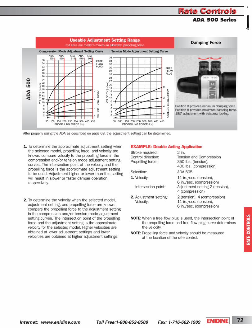
72Internet: www.enidine.com Toll Free:1-800-852-8508 Fax: 1-716-662-1909
RATE C
ON
TR
OLS
Rate ControlsRate ControlsADA 500 Series
EXAMPLE: Double Acting ApplicationStroke required: 2 in.Control direction: Tension and CompressionPropelling force: 350 lbs. (tension),
400 lbs. (compression)Selection: ADA 5051. Velocity: 11 in./sec. (tension),
6 in./sec. (compression)Intersection point: Adjustment setting 2 (tension),
4 (compression)2. Adjustment setting: 2 (tension), 4 (compression)
Velocity: 11 in./sec. (tension), 6 in./sec. (compression)
NOTE: When a free flow plug is used, the intersection point ofthe propelling force and free flow plug curve determinesthe velocity.
NOTE:Propelling force and velocity should be measured at the location of the rate control.
AD
A 5
00
Damping ForceUseable Adjustment Setting RangeRed lines are model’s maximum allowable propelling force.
Position 0 provides minimum damping force. Position 8 provides maximum damping force.180° adjustment with setscrew locking.
Compression Mode Adjustment Setting Curve Tension Mode Adjustment Setting Curve
1. To determine the approximate adjustment setting whenthe selected model, propelling force, and velocity areknown: compare velocity to the propelling force in thecompression and/or tension mode adjustment settingcurves. The intersection point of the velocity and the propelling force is the approximate adjustment settingto be used. Adjustment higher or lower than this settingwill result in slower or faster damper operation, respectively.
2. To determine the velocity when the selected model, adjustment setting, and propelling force are known:compare the propelling force to the adjustment setting in the compression and/or tension mode adjustment setting curves. The intersection point of the propellingforce and the adjustment setting is the approximatevelocity for the selected model. Higher velocities areobtained at lower adjustment settings and lower velocities are obtained at higher adjustment settings.
After properly sizing the ADA as described on page 68, the adjustment setting can be determined.
ShockCover5-2B 3/31/03 2:30 PM Page 72

Rate Controls AccessoriesRate Controls AccessoriesADA 500 Series
Internet: www.enidine.com Toll Free: 1-800-852-8508 Fax: 1-716-662-190973
RATE C
ON
TR
OLS
Accessories
Catalog No. Part Number Accessory Description LA Weight
RAC48 1K495748 Remote Adjustment Cable 48 7 ozNotes
RAC4957 AJ4957325 Adjustable Cartridge
NAC “x” NJ“x”4957327 Non-Adjustable Cartridge (0-6)
CW4957 2L4957302 Cartridge Wrench
FFP4957 PA4957326 Free Flow Plug
Enidine will custom fit a remoteadjustment cable for applicationswhere the ADA unit will be mountedin non-accessible locations. ContactEnidine for more information. Standard remote adjustment cable length is 48". Optional lengths available upon request.
Note: Remote adjustment cable can be used in a single position only.
Remote Adjustment Cable
“x” specify desired setting “0-6”. May be used in place of adjustable cartridge.
Provides least amount of damping force for ADA Models.
All dimensions in inches.
LA
For installing adjustable and non-adjustable cartridges.
Adjustable Cartridge Non-Adjustable CartridgeFree Flow Plug
ADA 505Select Catalog No. from Engineering Datachart or Accessory chart
Example:
10Select quantity
T4 Select Tension Mode •T Adjustable•T (0-6) Non-Adjustable*•P Free Flow
CSelect Compression Mode •C Adjustable•C (0-6) Non-Adjustable*•P Free Flow
*Note: Select adjustment setting (from Adjustment Setting Curve[s]) to be duplicated in non-adjustable cartridge.
Note: If rotary application, please complete application worksheet on page 81 and forward to Enidine.
Ordering Information
ShockCover5-2B 3/31/03 2:30 PM Page 73
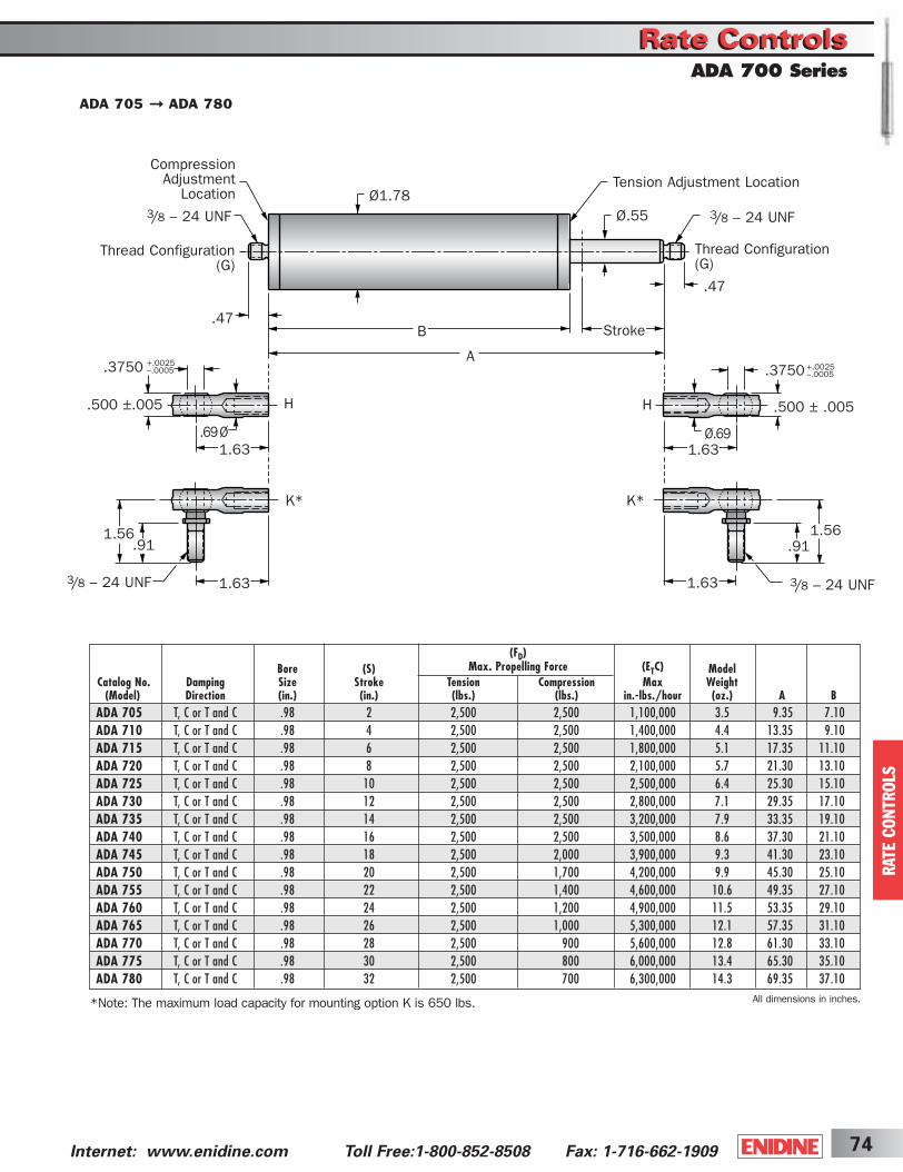
Rate ControlsRate ControlsADA 700 Series
74Internet: www.enidine.com Toll Free:1-800-852-8508 Fax: 1-716-662-1909
(FD)Bore (S) Max. Propelling Force (ETC) Model
Catalog No. Damping Size Stroke Tension Compression Max Weight(Model) Direction (in.) (in.) (lbs.) (lbs.) in.-lbs./hour (oz.) A B
ADA 705 T, C or T and C .98 2 2,500 2,500 1,100,000 3.5 9.35 7.10ADA 710 T, C or T and C .98 4 2,500 2,500 1,400,000 4.4 13.35 9.10ADA 715 T, C or T and C .98 6 2,500 2,500 1,800,000 5.1 17.35 11.10ADA 720 T, C or T and C .98 8 2,500 2,500 2,100,000 5.7 21.30 13.10ADA 725 T, C or T and C .98 10 2,500 2,500 2,500,000 6.4 25.30 15.10ADA 730 T, C or T and C .98 12 2,500 2,500 2,800,000 7.1 29.35 17.10ADA 735 T, C or T and C .98 14 2,500 2,500 3,200,000 7.9 33.35 19.10ADA 740 T, C or T and C .98 16 2,500 2,500 3,500,000 8.6 37.30 21.10ADA 745 T, C or T and C .98 18 2,500 2,000 3,900,000 9.3 41.30 23.10ADA 750 T, C or T and C .98 20 2,500 1,700 4,200,000 9.9 45.30 25.10ADA 755 T, C or T and C .98 22 2,500 1,400 4,600,000 10.6 49.35 27.10ADA 760 T, C or T and C .98 24 2,500 1,200 4,900,000 11.5 53.35 29.10ADA 765 T, C or T and C .98 26 2,500 1,000 5,300,000 12.1 57.35 31.10ADA 770 T, C or T and C .98 28 2,500 900 5,600,000 12.8 61.30 33.10ADA 775 T, C or T and C .98 30 2,500 800 6,000,000 13.4 65.30 35.10ADA 780 T, C or T and C .98 32 2,500 700 6,300,000 14.3 69.35 37.10
All dimensions in inches.
Tension Adjustment Location
3/8 – 24 UNFØ.55
.47
Ø1.78
.47
Thread Configuration(G)
Thread Configuration(G)
CompressionAdjustment
Location3/8 – 24 UNF
B
A
Stroke
.500 ±.005
.69 Ø
.3750 +.0025–.0005
1.63
3/8 – 24 UNF
1.56.91
1.63
H
K*
H
K*
.500 ± .005
Ø.69
.3750 +.0025–.0005
1.63
3/8 – 24 UNF
1.56.91
1.63
*Note: The maximum load capacity for mounting option K is 650 lbs.
RATE C
ON
TR
OLS
ADA 705 ➞ ADA 780
ShockCover5-2B 3/31/03 2:30 PM Page 74

Rate ControlsRate ControlsADA 700 Series
Internet: www.enidine.com Toll Free: 1-800-852-8508 Fax: 1-716-662-190975
RATE C
ON
TR
OLS
After properly sizing the ADA as described on page 68, the adjustment setting can be determined.1. To determine the approximate adjustment setting, when the
selected model, propelling force, and velocity are known, comparevelocity to the propelling force in the compression and/or tensionmode adjustment setting curves. The intersection point of the velocity and the propelling force is the approximate adjustment setting to be used. Adjustment lower or higher than this setting will result in slower or faster damper operation respectively.
2. To determine the velocity, when the selected model, adjustment set-ting, and propelling force are known, compare the propelling force tothe adjustment setting in the compression and/or tension mode adjustment setting curves. The intersection point of the propelling force and the adjustment setting is the approximate velocity for the selected model. Higher velocities are obtained at higher adjustment settings and lower velocities areobtained at lower adjustment settings.
3. A 1.5mm Hex Wrench (provided) is required to adjust the unit.
NOTE: When a free flow plug is used, the intersection point of the propelling force and free flow plug curve determines the velocity.
EXAMPLE: Adjustable Double Acting Rate Control ApplicationStroke required: 6 in.Control direction: Tension and CompressionPropelling force: 1,000 lbs. (tension), 1,625 lbs. (compression)Selection: ADA 7151. Velocity: 25 in./sec. (tension),
4 in./sec. (compression)Intersection point: Adjustment setting 11/2 (tension),
1/2 (compression)2. Adjustment setting: 11/2 (tension), 1/2 (compression)
Velocity: 25 in./sec. (tension), 4 in./sec. (compression)
NOTE:Propelling force and velocity should be measured at the location of the rate control.
AD
A 7
00
Damping ForceUseable Adjustment Setting RangeRed lines are model’s maximum allowable propelling force.
Turn adjustment pin 13/4 turns open to provide minimum damping force. Turn adjustment pin fully closed to provide maximum damping force.
125 250 375 500 625 750 875 1000 1125 1250 1375 1500 1625 1750 1875 2000 2125 2250 2375 2500 0
2
4
6
8
10
12
14
16
18
20
22
24
ADA775
ADA770
ADA760
ADA750
ADA745
ADA755
ADA780
ADA765
13/4
11/2
11/4
1
3/4
1/2
1/4
PROPELLING FORCE (lbs)
VE
LO
CIT
Y (
in/s
ec)
AD
JUS
TM
EN
T P
IN...
TU
RN
S O
PE
N
125 250 375 500 625 750 875 1000 1125 1250 1375 1500 1625 1750 1875 2000 2125 2250 2375 2500 0
5
10
15
20
25
30
35
40
45
50
PROPELLING FORCE (lbs)
VE
LO
CIT
Y (
in/s
ec)
AD
JUS
TM
EN
T P
IN...
TU
RN
S O
PE
N
13/4
11/2
11/4
1
3/4
1/2
1/4
Compression
Tension
ADA 770Model Designation
Example:
10Select quantity
T Tension Mode: Adjustable
(P = Free Flow)
CCompression Mode: Adjustable
(P = Free Flow)
HG - Threaded OnlyH - Swivel BearingK - Knee Joint
KG - Threaded OnlyH - Swivel BearingK - Knee Joint
Free Flow
125 250 375 500 625 750 875 1000 1125 1250 1375 1500 1625 1750 1875 2000 2125 2250 2375 2500 0
20
40
60
80
100
120
140
160
180
200
PROPELLING FORCE (lbs)
VE
LO
CIT
Y (
in/s
ec)
FREE FLOW in TENSION
FREE FLOW in COMPRESSION
ADA 700 Ordering Information
RATE C
ON
TR
OLS
ShockCover5-2B 3/31/03 2:30 PM Page 75
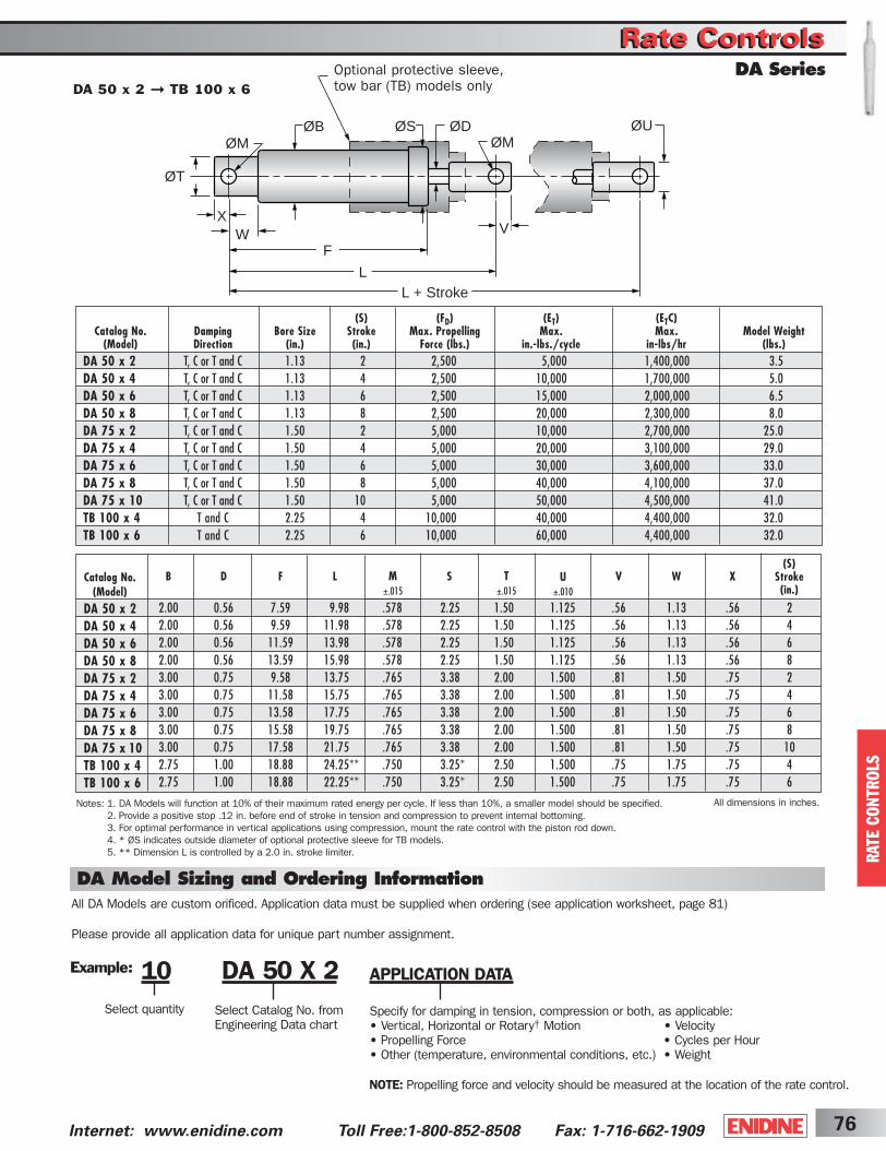
Rate ControlsRate ControlsDA Series
76Internet: www.enidine.com Toll Free:1-800-852-8508 Fax: 1-716-662-1909
ØM
Optional protective sleeve, tow bar (TB) models only
F
LL + Stroke
ØB ØD
V
ØU
ØT
XW
ØSØM
Notes: 1. DA Models will function at 10% of their maximum rated energy per cycle. If less than 10%, a smaller model should be specified.2. Provide a positive stop .12 in. before end of stroke in tension and compression to prevent internal bottoming.3. For optimal performance in vertical applications using compression, mount the rate control with the piston rod down.4. * ØS indicates outside diameter of optional protective sleeve for TB models.5. ** Dimension L is controlled by a 2.0 in. stroke limiter.
All dimensions in inches.
M±.015
T±.015
U±.010
Catalog No.(Model)
DA 50 x 2DA 50 x 4DA 50 x 6DA 50 x 8DA 75 x 2DA 75 x 4DA 75 x 6DA 75 x 8DA 75 x 10TB 100 x 4TB 100 x 6
(S)Stroke(in.)
(S) (FD) (ET) (ETC)Catalog No. Damping Bore Size Stroke Max. Propelling Max. Max. Model Weight
(Model) Direction (in.) (in.) Force (lbs.) in.-lbs./cycle in-lbs/hr (lbs.)DA 50 x 2 T, C or T and C 1.13 2 2,500 5,000 1,400,000 3.5DA 50 x 4 T, C or T and C 1.13 4 2,500 10,000 1,700,000 5.0DA 50 x 6 T, C or T and C 1.13 6 2,500 15,000 2,000,000 6.5DA 50 x 8 T, C or T and C 1.13 8 2,500 20,000 2,300,000 8.0DA 75 x 2 T, C or T and C 1.50 2 5,000 10,000 2,700,000 25.0DA 75 x 4 T, C or T and C 1.50 4 5,000 20,000 3,100,000 29.0DA 75 x 6 T, C or T and C 1.50 6 5,000 30,000 3,600,000 33.0DA 75 x 8 T, C or T and C 1.50 8 5,000 40,000 4,100,000 37.0DA 75 x 10 T, C or T and C 1.50 10 5,000 50,000 4,500,000 41.0TB 100 x 4 T and C 2.25 4 10,000 40,000 4,400,000 32.0TB 100 x 6 T and C 2.25 6 10,000 60,000 4,400,000 32.0
DA 50 x 2 ➞ TB 100 x 6
All DA Models are custom orificed. Application data must be supplied when ordering (see application worksheet, page 81)
Please provide all application data for unique part number assignment.
DA 50 X 2Select Catalog No. from Engineering Data chart
10Select quantity
APPLICATION DATA
Specify for damping in tension, compression or both, as applicable:• Vertical, Horizontal or Rotary† Motion • Velocity• Propelling Force • Cycles per Hour• Other (temperature, environmental conditions, etc.) • Weight
Example:
DA Model Sizing and Ordering Information
B D F L S V W X
2.00 0.56 7.59 9.98 .578 2.25 1.50 1.125 .56 1.13 .56 22.00 0.56 9.59 11.98 .578 2.25 1.50 1.125 .56 1.13 .56 42.00 0.56 11.59 13.98 .578 2.25 1.50 1.125 .56 1.13 .56 62.00 0.56 13.59 15.98 .578 2.25 1.50 1.125 .56 1.13 .56 83.00 0.75 9.58 13.75 .765 3.38 2.00 1.500 .81 1.50 .75 23.00 0.75 11.58 15.75 .765 3.38 2.00 1.500 .81 1.50 .75 43.00 0.75 13.58 17.75 .765 3.38 2.00 1.500 .81 1.50 .75 63.00 0.75 15.58 19.75 .765 3.38 2.00 1.500 .81 1.50 .75 83.00 0.75 17.58 21.75 .765 3.38 2.00 1.500 .81 1.50 .75 102.75 1.00 18.88 24.25** .750 3.25* 2.50 1.500 .75 1.75 .75 42.75 1.00 18.88 22.25** .750 3.25* 2.50 1.500 .75 1.75 .75 6
NOTE: Propelling force and velocity should be measured at the location of the rate control.
RATE C
ON
TR
OLS
ShockCover5-2B 3/31/03 2:30 PM Page 76
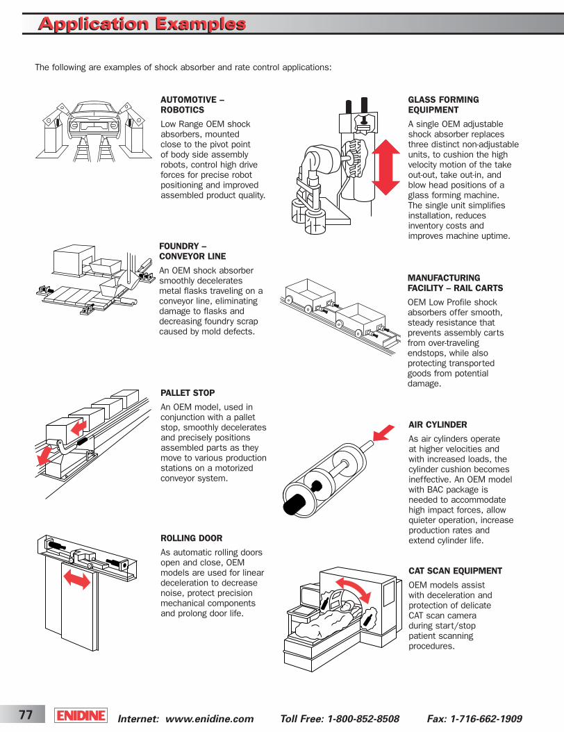
Internet: www.enidine.com Toll Free: 1-800-852-8508 Fax: 1-716-662-190977
Application ExamplesApplication Examples
FOUNDRY –CONVEYOR LINE
An OEM shock absorbersmoothly decelerates metal flasks traveling on aconveyor line, eliminatingdamage to flasks anddecreasing foundry scrapcaused by mold defects.
GLASS FORMINGEQUIPMENT
A single OEM adjustableshock absorber replacesthree distinct non-adjustableunits, to cushion the highvelocity motion of the takeout-out, take out-in, andblow head positions of aglass forming machine. The single unit simplifiesinstallation, reduces inventory costs andimproves machine uptime.
MANUFACTURING FACILITY – RAIL CARTS
OEM Low Profile shockabsorbers offer smooth,steady resistance thatprevents assembly cartsfrom over-traveling endstops, while also protecting transportedgoods from potential damage.
AUTOMOTIVE – ROBOTICS
Low Range OEM shockabsorbers, mounted close to the pivot point of body side assemblyrobots, control high driveforces for precise robotpositioning and improvedassembled product quality.
CAT SCAN EQUIPMENT
OEM models assist with deceleration and protection of delicate CAT scan camera during start/stop patient scanning procedures.
ROLLING DOOR
As automatic rolling doorsopen and close, OEM models are used for lineardeceleration to decreasenoise, protect precisionmechanical componentsand prolong door life.
PALLET STOP
An OEM model, used inconjunction with a palletstop, smoothly deceleratesand precisely positionsassembled parts as theymove to various productionstations on a motorizedconveyor system.
AIR CYLINDER
As air cylinders operate at higher velocities and with increased loads, thecylinder cushion becomesineffective. An OEM modelwith BAC package is needed to accommodatehigh impact forces, allowquieter operation, increaseproduction rates andextend cylinder life.
The following are examples of shock absorber and rate control applications:
ShockCover5-2B 3/31/03 2:30 PM Page 77

78Internet: www.enidine.com Toll Free:1-800-852-8508 Fax: 1-716-662-1909
PACKAGING MACHINERY
Standard HP models control rapid movement of a table transporting loaded packages to anautomated case packersealing station, for safeand precise machineryoperation.
ROBOTIC ASSEMBLYEQUIPMENT
Use of an HP 110 on high speed robotic assembly equipment prevents potential equipment damage fromslide mechanism overrunand increases maximum equipment operatingspeed.
AUTOMOTIVE – TRANSFER LINE
Automated assemblyplants use OEM largeshock absorbers extensively to decelerateand protect shuttle/transfer line systems. This is especially beneficialin the robotic welding location.
PAPER ROLLS
Shock absorbers used inconjunction with stop armmechanisms/air cylindersquickly decelerate largepaper rolls moving throughproduction on inclinedplanes, without damage or jolting. This increasesoperating speed anddecreases machinery damage and paper waste.
PRINTING
An OEM large shockabsorber assists in paper positioning and prevents equipment damage during printingtest runs (when the pressis stopped frequently toconfirm proper colors,focus and paper position).
AIR CYLINDER
Special OEM series shockabsorber installed on atrunion mounted, thru-rodpneumatic cylinderabsorbs the energy created from this driveactuator, which controlsthe seal and cut operationon a vertical form, fill sealand packaging machine.
Applications ExamplesApplications Examples
ShockCover5-2B 3/31/03 2:30 PM Page 78
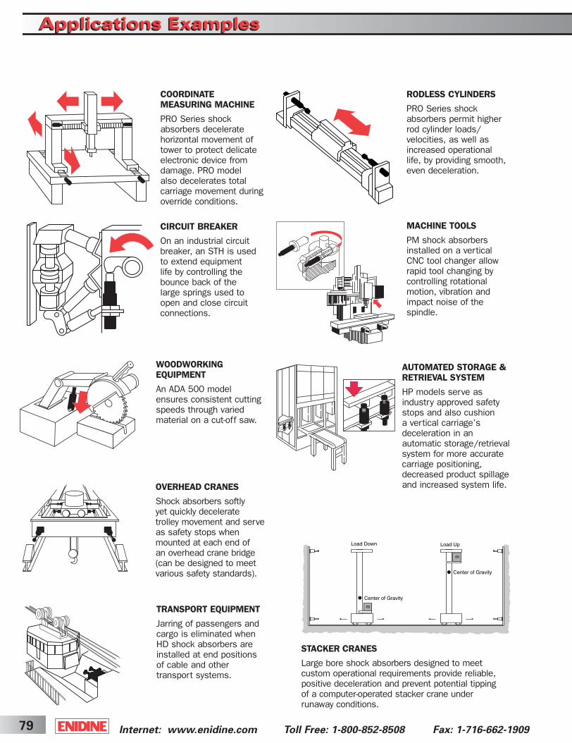
Internet: www.enidine.com Toll Free: 1-800-852-8508 Fax: 1-716-662-190979
Applications ExamplesApplications Examples
AUTOMATED STORAGE &RETRIEVAL SYSTEM
HP models serve as industry approved safetystops and also cushion a vertical carriage’s deceleration in an automatic storage/retrieval system for more accuratecarriage positioning,decreased product spillageand increased system life.
WOODWORKING EQUIPMENT
An ADA 500 modelensures consistent cuttingspeeds through variedmaterial on a cut-off saw.
RODLESS CYLINDERS
PRO Series shockabsorbers permit higherrod cylinder loads/velocities, as well asincreased operational life, by providing smooth,even deceleration.
COORDINATE MEASURING MACHINE
PRO Series shockabsorbers decelerate horizontal movement oftower to protect delicateelectronic device fromdamage. PRO model also decelerates total carriage movement duringoverride conditions.
MACHINE TOOLS
PM shock absorbersinstalled on a vertical CNC tool changer allowrapid tool changing by controlling rotationalmotion, vibration andimpact noise of the spindle.
CIRCUIT BREAKER
On an industrial circuitbreaker, an STH is used to extend equipment life by controlling thebounce back of the large springs used toopen and close circuitconnections.
OVERHEAD CRANES
Shock absorbers softly yet quickly decelerate trolley movement and serveas safety stops when mounted at each end of an overhead crane bridge(can be designed to meet various safety standards).
TRANSPORT EQUIPMENT
Jarring of passengers andcargo is eliminated whenHD shock absorbers areinstalled at end positionsof cable and othertransport systems.
STACKER CRANES
Large bore shock absorbers designed to meet custom operational requirements provide reliable, positive deceleration and prevent potential tipping of a computer-operated stacker crane under runaway conditions.
ShockCover5-2B 3/31/03 2:30 PM Page 79
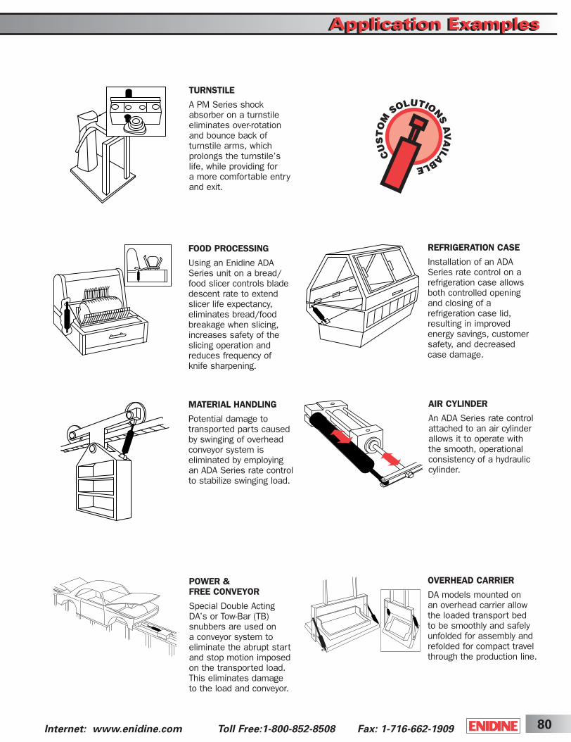
80Internet: www.enidine.com Toll Free:1-800-852-8508 Fax: 1-716-662-1909
POWER & FREE CONVEYOR
Special Double Acting DA’s or Tow-Bar (TB) snubbers are used on a conveyor system to eliminate the abrupt startand stop motion imposedon the transported load.This eliminates damage to the load and conveyor.
MATERIAL HANDLING
Potential damage to transported parts causedby swinging of overheadconveyor system is eliminated by employing an ADA Series rate controlto stabilize swinging load.
OVERHEAD CARRIER
DA models mounted on an overhead carrier allow the loaded transport bed to be smoothly and safelyunfolded for assembly andrefolded for compact travelthrough the production line.
FOOD PROCESSING
Using an Enidine ADASeries unit on a bread/food slicer controls bladedescent rate to extendslicer life expectancy, eliminates bread/food breakage when slicing,increases safety of the slicing operation andreduces frequency of knife sharpening.
REFRIGERATION CASE
Installation of an ADA Series rate control on arefrigeration case allowsboth controlled opening and closing of a refrigeration case lid, resulting in improved energy savings, customersafety, and decreased case damage.
AIR CYLINDER
An ADA Series rate controlattached to an air cylinderallows it to operate with the smooth, operational consistency of a hydrauliccylinder.
TURNSTILE
A PM Series shockabsorber on a turnstileeliminates over-rotationand bounce back of turnstile arms, which prolongs the turnstile’slife, while providing for a more comfortable entry and exit.
Application ExamplesApplication Examples
ShockCover5-2B 3/31/03 2:30 PM Page 80
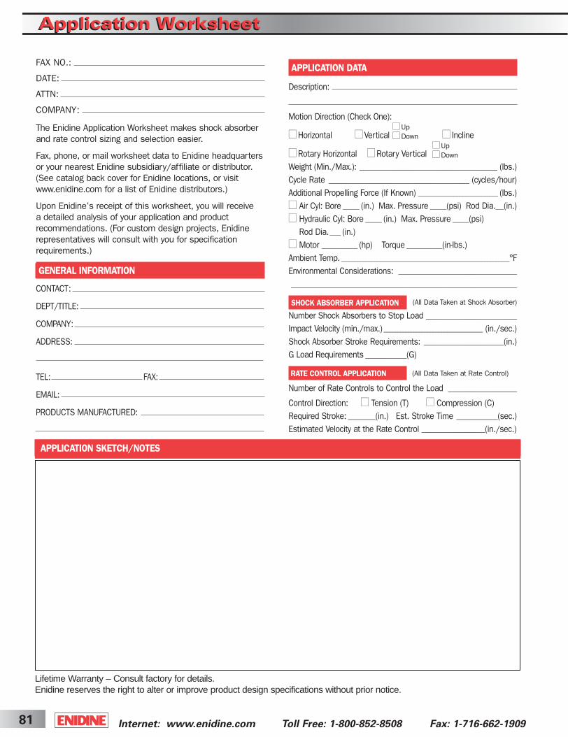
Internet: www.enidine.com Toll Free: 1-800-852-8508 Fax: 1-716-662-190981
Application WorksheetApplication Worksheet
The Enidine Application Worksheet makes shock absorberand rate control sizing and selection easier.
Fax, phone, or mail worksheet data to Enidine headquartersor your nearest Enidine subsidiary/affiliate or distributor. (See catalog back cover for Enidine locations, or visitwww.enidine.com for a list of Enidine distributors.)
Upon Enidine’s receipt of this worksheet, you will receive a detailed analysis of your application and product recommendations. (For custom design projects, Enidinerepresentatives will consult with you for specificationrequirements.)
GENERAL INFORMATION
CONTACT:
DEPT/TITLE:
COMPANY:
ADDRESS:
TEL: FAX:
EMAIL:
PRODUCTS MANUFACTURED:
APPLICATION DATA
Description:
Motion Direction (Check One):
■■ Horizontal ■■ Vertical ■■ Incline
■■ Rotary Horizontal ■■ Rotary VerticalWeight (Min./Max.): __________________________________________________ (lbs.)Cycle Rate ___________________________________________________ (cycles/hour)Additional Propelling Force (If Known) _____________________________ (lbs.)■■ Air Cyl: Bore ______ (in.) Max. Pressure ______(psi) Rod Dia.___(in.)■■ Hydraulic Cyl: Bore ______ (in.) Max. Pressure ______(psi)
Rod Dia.____ (in.)■■ Motor _____________ (hp) Torque _____________(in-lbs.)Ambient Temp. _____________________________________________________________°FEnvironmental Considerations: ___________________________________________
__________________________________________________________________________________
SHOCK ABSORBER APPLICATION
Number Shock Absorbers to Stop Load _________________________________
Impact Velocity (min./max.) ____________________________________ (in./sec.)Shock Absorber Stroke Requirements: _____________________________(in.)G Load Requirements _______________(G)
RATE CONTROL APPLICATION
Number of Rate Controls to Control the Load _________________________
Control Direction: ■■ Tension (T) ■■ Compression (C)Required Stroke: __________(in.) Est. Stroke Time _______________(sec.)Estimated Velocity at the Rate Control _______________________(in./sec.)
FAX NO.:
DATE:
ATTN:
COMPANY:
■■ Up■■ Down
■■ Up■■ Down
(All Data Taken at Shock Absorber)
(All Data Taken at Rate Control)
APPLICATION SKETCH/NOTES
Lifetime Warranty – Consult factory for details.Enidine reserves the right to alter or improve product design specifications without prior notice.
ShockCover5-2B 3/31/03 2:30 PM Page 81
Cover2003 3/31/03 2:14 PM Page 4

Enidine Incorporated7 Centre DriveOrchard Park, New York 14127 • USAPhone: 716-662-1900Fax: 716-662-1909www.enidine.com
Subsidiaries and Affiliates:
Enidine West184 Technology Dr., Suite 201Irvine, California 92618 • USAPhone: 949-727-9112Fax: 949-727-9107www.enidine.com
Enidine GmbHRheinauenstr, 579415 Bad BellingenRheinweiler • GermanyPhone: 49 7635 8101 0Fax: 49 7635 8101 99www.enidine.de
Enidine Co. Ltd.398, Chigasaki-Cho, Tsuzuki-KuYokohama-Shi, Kanagawa 224-0031JapanPhone: 81 45 947 1671Fax: 81 45 945 3967www.enidine.co.jp
Enidine Corporativo De Mexico, S.A. de C.V.Av. Patria 3124-ACol El SauzGuadalajara, CP Jalisco • Mexico 45080Phone: 52 36 45 4414Fax: 52 333 646-0070www.enidine.com.mx
Enidine U.K. Ltd.Patrick Gregory RoadWolverhampton West Midlands, WV11 3DZUnited KingdomPhone: 44 1902 304000Fax: 44 1902 305676www.enidine.co.uk
ENIDINE INDUSTRIAL PRODUCTSShock Absorbers • Rate Controls • Air Springs • One-Shot Emergency Stops
Elastomeric Isolators • Wire Rope Isolators • Compact Wire Rope Isolators • Heavy Industry Buffers
Solutions in Energy Absorption and Vibration Isolation.
Shock
Abso
rber an
d R
ate C
ontro
l Pro
duct C
atalog
CGGSRCMI 03/03 20M
Cover2003 3/31/03 2:13 PM Page 1


