

London, UK, May 29-31, 2012 ATACCS’2012 | RESEARCH PAPERS
107
Simulated Trajectories Generation
Jaime García Sáez
Air Traffic Management Directorate
INECO
Madrid, Spain
+34 914521398
ABSTRACT
This document bases on an innovation project by INECO
aimed at developing and integrating a flight simulator in
ATM (Air Traffic Management) simulation platforms. The
paper documents a method for generation of aircraft flyable
trajectories based on a simulation engine instead of
calculated trajectories [1].
Categories and Subject Descriptors
J.2 [Physical Sciences and Engineering]: Aerospace.
General Terms
Performance, Simulation.
Keywords
Simulated trajectories; average flight; simulation engine;
aircraft modeling
INTRODUCTION
This paper focuses on the flight trajectory generation tools
available within the Flyability Simulator project, although
these introductory words are intended to present the whole
project. The main goal of the Flyability Simulator is the
development and installation of a flight simulator that truly
reflects the aircraft performances and studies the flyability
of the instrumental procedures designed within the
Aeronautical DG (Directorate General) of INECO.
Increased deployment and use of Area Navigation (RNAV)
leads to more diversified navigation routes and to improved
utilization of available airspace. This paper introduces a
competitive tool to generate flight trajectories, providing
aircraft models (Flight Dynamic Model and Flight Control
System, autopilot, engines) and a simulation environment to
test instrumental procedures. Computer simulations of air
traffic are a major source of quantified estimates of system
benefits. So, this tool is also intended for ongoing SESAR
initiatives and any other project requiring simulated
trajectories for disparate purposes.
In this paper, it will be shown the difference between a
geometric model to calculate user-flavored trajectories out
of a RNAV procedure and the simulation of a procedure by
mean of a simulation engine. By user-flavored, it is meant
the user could select some input conditions to calculate the
trajectory and later check if a flyable trajectory was
produced. In this context, some algorithms which seek to
ensure sufficient accuracy and matching between procedure
and trajectory are proposed.
On the other hand, simulated trajectories rely on modeled
performances and aerodynamics of commercial aircrafts, so
trajectories got from running a simulation engine give a
fresh understanding of the way some maneuvers are
performed in real world.
THE NEED
There is a need to have a tool able to go beyond current
approaches in the RNAV procedure simulations field.
Nowadays checking against a set of known coding rules
(ICAO norms [5] in doc 8168, ARINC spec 424) is quite
usual and mature enough to state that there are
inconveniences in this approach. If we think in the short and
long future, that approach does not reflect the real
performance of current aircrafts and does not take into
account other scenarios out of a single flight.
Computation based in existing rules is nevertheless quite
important as studies of coverage and noise can contribute
significantly to the adoption of some procedures in an
airport and surroundings. The tools Procedure Validation
Tool and Average Trajectory Generation Tool aim to the
aforementioned goal. But, the Simulated Trajectory
Generation Tool goes one step further verifying arrival,
departure, approach, missed approach and en route
instrumental procedures with a wide range of testing, taking
into account different aircraft models, different weights and
different weather conditions (temperature and wind).
Firstly, we followed the ICAO 9906 norm that details the
Quality Assurance Manual for Flight Procedure Design in
the development of the Procedure Validation Tool, but then
we developed new ways of implementing the ground
validation of RNAV procedures based on simulations
instead of coded rules.
To this respect, a practical and usable model requires
sufficient modeling detail to allow evaluations of the impact
of alternative route designs and navigational procedures
Permission to make digital or hard copies of all or part of this
work for personal or classroom use is granted without fee
provided that copies are not made or distributed for profit or
commercial advantage and that copies bear this notice and the
full citation on the first page. Re-publication of material on this
page requires permission by the copyright owners.
ATACCS’2012, 29-31 May 2012, London, UK.
Copyright 2012 IRIT PRESS, ISBN: 978-2-917490-20-4

London, UK, May 29-31, 2012 ATACCS’2012 | RESEARCH PAPERS
108
while limiting simulation run times. This was a challenge at
the beginning of the project. The answer to this challenge is
the Simulated Trajectory Generation Tool. Variability in
aircraft operational or navigational performance and
external meteorological conditions may need repeated
searches for desired solutions. Consequently, rapid
generation of flight trajectories under disparate input
parameters is desirable. Hiding programming details of a
simulation engine in a nice and user-oriented interface was
another goal of the Simulated Trajectory Generation Tool.
APPROACH
Operations
There is a rising trend that simulation-based validation of
new and/or updated procedures is a crucial step in
Procedure Design. Concretely, this step covers the
following operations:
Checking for completeness of data and path
terminator sequences (PVT tool in Figure 1).
Validating distances to/from waypoints, courses
between waypoints, stabilization distance, etc.
(PVT and ATGT tools in Figure 1).
Generation of average flight (implemented for DF
(direct to a fix), TF (track to a fix), CF (course to a
fix) and CA (course to an altitude) path
terminators and FlyBy/FlyOver transitions)
(ATGT tool in Figure 1).
Checking along the trajectory for the fulfillment of
signal quality requirements in terms of accuracy,
availability, service continuity and integrity, as
well as radio electric coverage DME/DME or
GNSS. Line of sight and power coverage studies
are performed in order to know if the aircraft is in
direct view from a radio help element. In other
words, we verify if the aircraft is covered by a
terrestrial station. This function was implemented
in conjunction with COVER tools, developed by
INECO (PVT and ATGT tools in Figure 1).
Checking flyability through a simulation engine
(STGT tool in Figure 1).
The goal of this step is operational safety, taking into
account how to clear obstacles in a safe way. For this
purpose, according to the navigational sensor, each phase of
a flight uses a set of protection surfaces through the
trajectory and a set of values for obstacles clearance. The
surfaces are defined in the most unfavorable case, assuring
that all trajectories flown by different kind of aircrafts are
within operational margins.
Once the procedure is designed and after some subsequent
stages, the maneuvers are published and some problems
may arise since then, such as lack of signal quality, fleet
that cannot meet the requirements and clash of adjustment
to initial requisites.
The forecast of the aforementioned problems is very
important from a social, political and economical
perspective, so that a previous simulation is necessary for
checking procedures in real situations and reducing the time
needed to publish the final procedure. The disparate tools
within the Flyability Simulator tackle that goal, especially
the STGT tool, main contribution and innovation of the
work presented in this paper.
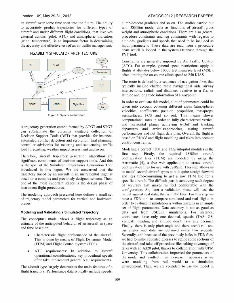
Architecture
In a nutshell, the Figure 1 shows up a high level view of the
Simulator architecture and its connection with external
tools, such as Google Earth, NASA World Wind, Radar
data source and COVER Apps (a suite of tools developed
by INECO that provide software tools for coverage
calculations using IF-77 based power studies and line of
sight radioeletric propagation with or without artificial
obstacles).
There is a Procedure Validation Tool (PVT), an Average
Trajectory Generation Tool (ATGT), a Simulated
Trajectory Generation Tool (STGT) and a Trajectory
Visualization Tool (TVT). There are main entities
connecting the tools, which are the Procedure and
Trajectory. There are files generated in two main basic
formats, such as CSV and KML. Finally, simulator engines
are used such as JSBSim [2] (an open-source flight
dynamics model) and Flight Gear [3] (an open-source flight
simulator) in order to test procedures and graphically
analyze the results.
JSBSim is a non-linear 6DOF (Degrees of Freedom)
dynamic simulator aimed for aerodynamic simulations.
JSBSim relies on the concept of force and moment build up
using stability derivatives. These are function of the
aerodynamics coefficients which mainly depend on the
geometry of the airplane.
Technically, the Simulator checks the functions of a
procedure under different conditions before its approval,
testing it against a low cost and wide set of studies. The
mathematical models are complex (especially when
calculating the average path flight) and they intend to
faithfully reproduce the inputs to the real system. But
aircrafts do not react as these models predict, so a new
approach based on real models is preferable to the current
one. This new approach is developed in the STGT tool.
With this support tool, some uncertainties in the running of
some services are considerably reduced to a minimum (for
instance, delays in procedure publication as an important
service quality factor) and the airport authorities may rely in
this decision-support element to know before real operation
the effectiveness of some measures and improve the
resource usage.
A 4-dimensional (4D) trajectory prediction contains data
specifying the predicted horizontal and vertical position of
London, UK, May 29-31, 2012 ATACCS’2012 | RESEARCH PAPERS
109
an aircraft over some time span into the future. The ability
to accurately predict trajectories for different types of
aircraft and under different flight conditions, that involves
external actions (pilot, ATC) and atmospheric indicators
(wind, temperature), is an important factor in determining
the accuracy and effectiveness of an air traffic management.
Figure 1: System Architecture
A trajectory generation combo formed by ATGT and STGT
can substantiate the currently available collection of
Decision Support Tools (DST) that provide, for instance,
automated conflict detection and resolution, trial planning,
controller advisories for metering and sequencing, traffic
load forecasting, weather impact assessment and so on.
Therefore, aircraft trajectory generation algorithms are
significant components of decision support tools. And this
is the goal of the Simulated Trajectories Generation Tool
introduced in this paper. We are concerned that the
trajectory traced by an aircraft in an instrumental flight is
based on a complex and previously designed schema. Then,
one of the most important stages is the design phase of
instrument flight procedures.
The modeling approach presented here defines a small set
of trajectory model parameters for vertical and horizontal
planes.
Modeling and Validating a Simulated Trajectory
The conceptual model views a flight trajectory as an
estimate of the anticipated behavior of an aircraft in space
and time based on:
Characteristic flight performance of the aircraft:
This is done by means of Flight Dynamics Model
(FDM) and Flight Control System (FCS).
ATC requirements: In addition to aircraft
operational considerations, key procedural speeds
often take into account general ATC requirements.
The aircraft type largely determines the main features of a
flight trajectory. Performance data typically include speeds,
climb/descent gradients and so on. The studies carried out
with JSBSim model data as functions of aircraft gross
weight and atmospheric conditions. There are also general
procedure constraints and leg constraints with regards to
altitudes, gradients and speeds that need to be included as
input parameters. These data are read from a procedure
chart which is loaded in the system Database through the
PVT tool.
Constraints are generally imposed by Air Traffic Control
(ATC). For example, general speed restrictions apply to
flights at altitudes below 10000 feet mean sea level (MSL),
often limiting the on-course climb speed to 250 KIAS.
The route is defined by a sequence of navigation fixes that
typically include charted radio navigational aids, airway
intersections, radials and distances relative to a fix, or
latitude and longitude information of a waypoint.
In order to evaluate this model, a lot of parameters could be
taken into account covering different areas (atmosphere,
velocities, coefficients, position, propulsion, massprops,
aerosurfaces, FCS and so on). This means slower
computational rates in order to fully characterized vertical
and horizontal planes achieving 6-Dof and tracking
departures and arrivals/approaches, testing aircraft
performances and not flight data plan. Overall, the flight is
based on RNAV and flight modeling and takes into account
control constraints.
Modeling a correct FDM and FCS/autopilot modules is the
first step. Firstly, the required JSBSim aircraft
configuration files (FDM) are modeled by using the
Aeromatic [4], a free web application to create aircraft
configuration files for use with JSBSim. This step allows us
to model several aircraft types as it is quite straightforward
and less time-consuming to get a raw FDM file for a
specific aircraft. The difficult part is achieving such degree
of accuracy that makes us feel comfortable with the
configuration. So, later a validation phase will test the
model against real data, that is, FDR files. For this step we
have a FDR tool to compare simulated and real flights in
order to evaluate if simulation is within margins in an ample
set of flight parameters. Data accuracy is not as good as
data got from JSBSim simulations. For instance,
coordinates have only one decimal, speeds (TAS, GS,
vertical), heading and altitude don’t have any decimal.
Finally, there is only pitch angle and there aren’t roll and
psi angles and data are obtained every two seconds. Secondly, and because of the previously lacks in FDR files,
we had to make educated guesses to refine some sections of
the aircraft and take-off procedure files taking advantage of
talks with an A320 pilot, thanks to collaboration with UPM
University. This collaboration improved the parameters of
the model and resulted in an increase in accuracy as we
were modeling from real world to a simulation
environment. Then, we are confident to use the model in
London, UK, May 29-31, 2012 ATACCS’2012 | RESEARCH PAPERS
110
other instrument procedures and under different weather
and mass conditions.
Further testing should follow in collaboration with airlines,
testing pilots and manufacturers, if possible, so we could
extend our models accordingly. Our purpose is modeling
real operation of an instrument procedure, so any actor in
the value chain could help us improving the automation in a
simulation environment.
Also, new algorithms have been implemented for
longitudinal and lateral control. The first one is an
implementation of total-energy control which allows us to
control speed and altitude simultaneously using a Multiple
Input Multiple Output (MIMO) control strategy. We used
the 6-Dof simulation to test and tune the parameters for an
A320 aircraft. For lateral control, we developed a channel
for controlling the bank angle parameter in turns. All those
controls are used for correct navigation in the sequence of
legs defined in a procedure chart. These controls are good
enough to achieve precise navigation, so testing a procedure
under design with JSBSim provides relevant information to
procedure designers in order to satisfy publication
requirements.
Then, the flight path needed to be followed by the autopilot
was constructed from a procedure chart stored in the
Flyability Simulator Database. That chart was automatically
translated to maneuvers events in a following step. Finally,
running the simulation and computing live the distances to
waypoints, turn ratios, taking decisions in order to advance
to next fix, checking restrictions and so on. The goal is a
flight as exact as possible to a real one. As said, checkings
against Flight Data Recorder were made in order to revise
the models and assure parameters related to position,
velocities, etc., are within margins.
The flight simulation is script based. The complete
parameters of the aircraft, initial data, engine data, FCS,
autopilot and procedure are provided in files in the xml
format. JSBSim carries out then a flight dynamic simulation
in object-oriented programming.
Modeling the Simulation Environment
Several files are involved in modeling the aircraft. The
aircraft’s metrics and aerodynamics characteristics
(airframe geometry, mass and inertia properties, landing
gear positions and their ground reactions, propulsion
system, flight control system, and aerodynamic
characteristics) are specified in the main aircraft
configuration file. The aircraft’s propulsion system is
specified in the engine and thruster files. The classic build
up method was used to model the aerodynamic forces and
moments (drag, side force, and lift forces, and roll, pitch,
and yaw moments) acting on the aircraft. Many factors
affect each of the forces and moments. The total force or
moment is the sum of the individual effect. It’s worth
remarking that this section was generated automatically by
Aeromatic. Although, the Aeromatic gives a fast and
effective way to construct the aircraft configuration files,
some important refinements are required. The use of
available data from Flight Data Records was the missing
part that was required to get a good JSBSim model. So,
FDRs were used in order to partially validate the models in
JSBSim as manufacturer’s data are hard to obtain.
STGT tool provides a Web environment to non-expert users
in order to create a new simulation, introduce the input
parameters (procedure, aircraft, meteo data, and weight),
launch the execution of the simulation in the JSBSim, get
the output data and process results. Also, a flight simulator
such as FlightGear is available in the integration
environment by which research and visualizations can be
carried out.
As we perform autonomous flight simulation, an autopilot
configuration file is added with the control operations
detailed so far. We started from PID (Proportional, Integral,
and Derivative) controller used in the JSBSim autopilot,
then we modeled the configuration file and the Autopilot
tuning process and, finally, the flight path was constructed
and deployed within the JSBSim navigation system thanks
to the simulated procedure XML file. The functions in the
autopilot are built using a PID algorithm. Typically a PID
controller manipulates one control output to force a current
value (or process value) towards a target value (or reference
point).
One of the issues in trajectory generation is to measure how
accurately a model will fit to a target trajectory. There is a
category named morphological similarity, which is followed
in our approach. It differs from other metrics such as time
coincidence, space coincidence and 4D coincidence in
nature due to an intrinsic distance between trajectories
considered as curves in a 3D space can be derived from
Riemannian geometry. Since only the shape of the
trajectory is taken into account, this metric is relevant
mainly for trajectory design tools, which is the case in
ATGT tool.
The generation starts from a flight intent defined in a
procedure and aircraft performances defined in a simulation
engine. Then, with initial conditions there is an
infrastructure to calculate average flights and simulate
flights taking modeled aircrafts. If possible, there will be a
comparison with flight plan and actual trajectory in case
computation on known procedures is carried out. The next
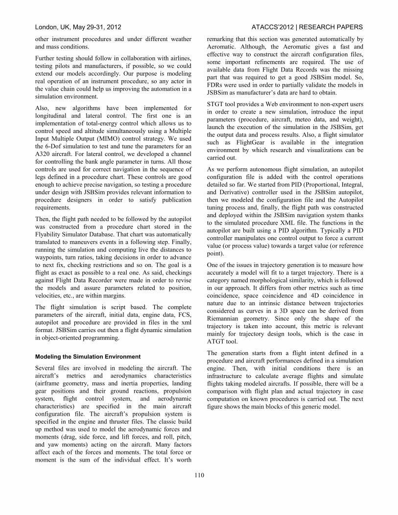
figure shows the main blocks of this generic model.
London, UK, May 29-31, 2012 ATACCS’2012 | RESEARCH PAPERS
111
Figure 2: Model Interactions
With regards to the infrastructure, there are different data
domains: Data domain, Meteo domain and Aeronautical
domain. Then, there is a service layer distributed in four
applications sharing the data layer and providing different
human-machine interfaces to the final user. The basic
interactions between the applications are either publishing
or request/reply.
The Process in Snapshots
How do we get a simulated trajectory out of a procedure
definition? In the following figures, the process is
represented:
Figure 3: AIP procedure
The input to the PVT tool is an instrumental procedure
either published or under design. In Figure 3, both
graphical (in green) and textual descriptions are provided.
This procedure is loaded in the Flyability Simulator
database.
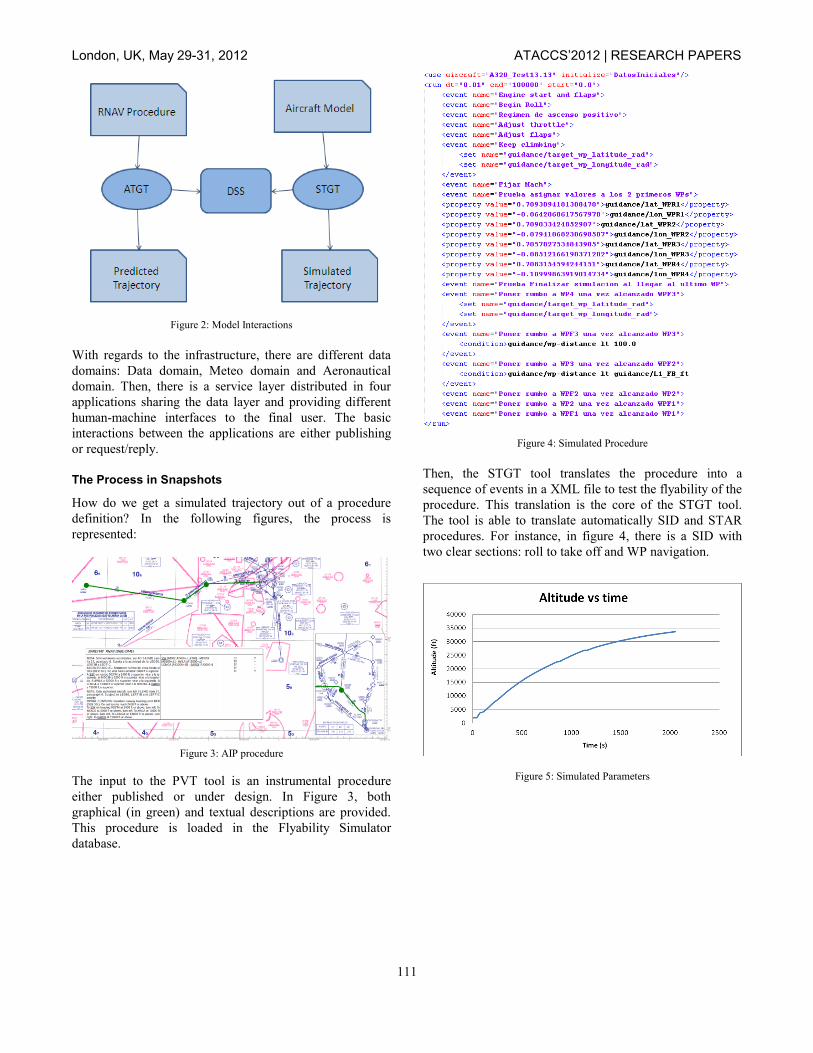
Figure 4: Simulated Procedure
Then, the STGT tool translates the procedure into a
sequence of events in a XML file to test the flyability of the
procedure. This translation is the core of the STGT tool.
The tool is able to translate automatically SID and STAR
procedures. For instance, in figure 4, there is a SID with
two clear sections: roll to take off and WP navigation.
Figure 5: Simulated Parameters
London, UK, May 29-31, 2012 ATACCS’2012 | RESEARCH PAPERS
112
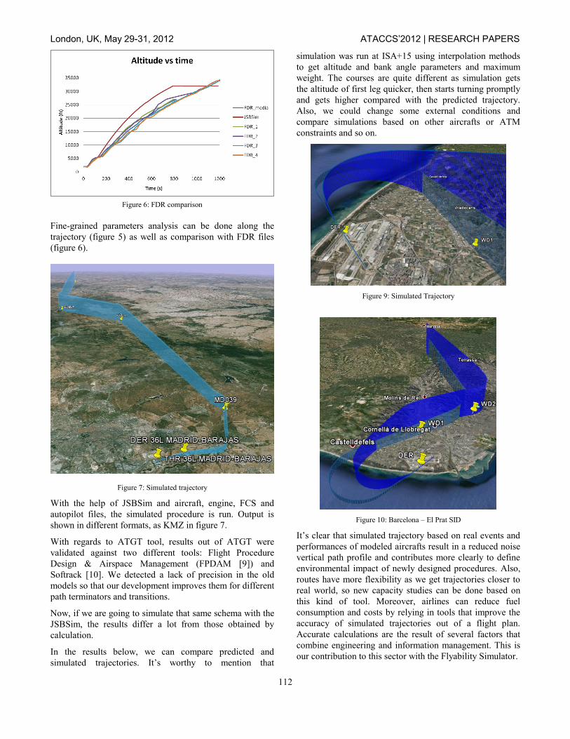
Figure 6: FDR comparison
Fine-grained parameters analysis can be done along the
trajectory (figure 5) as well as comparison with FDR files
(figure 6).
Figure 7: Simulated trajectory
With the help of JSBSim and aircraft, engine, FCS and
autopilot files, the simulated procedure is run. Output is
shown in different formats, as KMZ in figure 7.
With regards to ATGT tool, results out of ATGT were
validated against two different tools: Flight Procedure
Design & Airspace Management (FPDAM [9]) and
Softrack [10]. We detected a lack of precision in the old
models so that our development improves them for different
path terminators and transitions.
Now, if we are going to simulate that same schema with the
JSBSim, the results differ a lot from those obtained by
calculation.
In the results below, we can compare predicted and
simulated trajectories. It’s worthy to mention that
simulation was run at ISA+15 using interpolation methods
to get altitude and bank angle parameters and maximum
weight. The courses are quite different as simulation gets
the altitude of first leg quicker, then starts turning promptly
and gets higher compared with the predicted trajectory.
Also, we could change some external conditions and
compare simulations based on other aircrafts or ATM
constraints and so on.
Figure 9: Simulated Trajectory
Figure 10: Barcelona – El Prat SID
It’s clear that simulated trajectory based on real events and
performances of modeled aircrafts result in a reduced noise
vertical path profile and contributes more clearly to define
environmental impact of newly designed procedures. Also,
routes have more flexibility as we get trajectories closer to
real world, so new capacity studies can be done based on
this kind of tool. Moreover, airlines can reduce fuel
consumption and costs by relying in tools that improve the
accuracy of simulated trajectories out of a flight plan.
Accurate calculations are the result of several factors that
combine engineering and information management. This is
our contribution to this sector with the Flyability Simulator.
London, UK, May 29-31, 2012 ATACCS’2012 | RESEARCH PAPERS
113
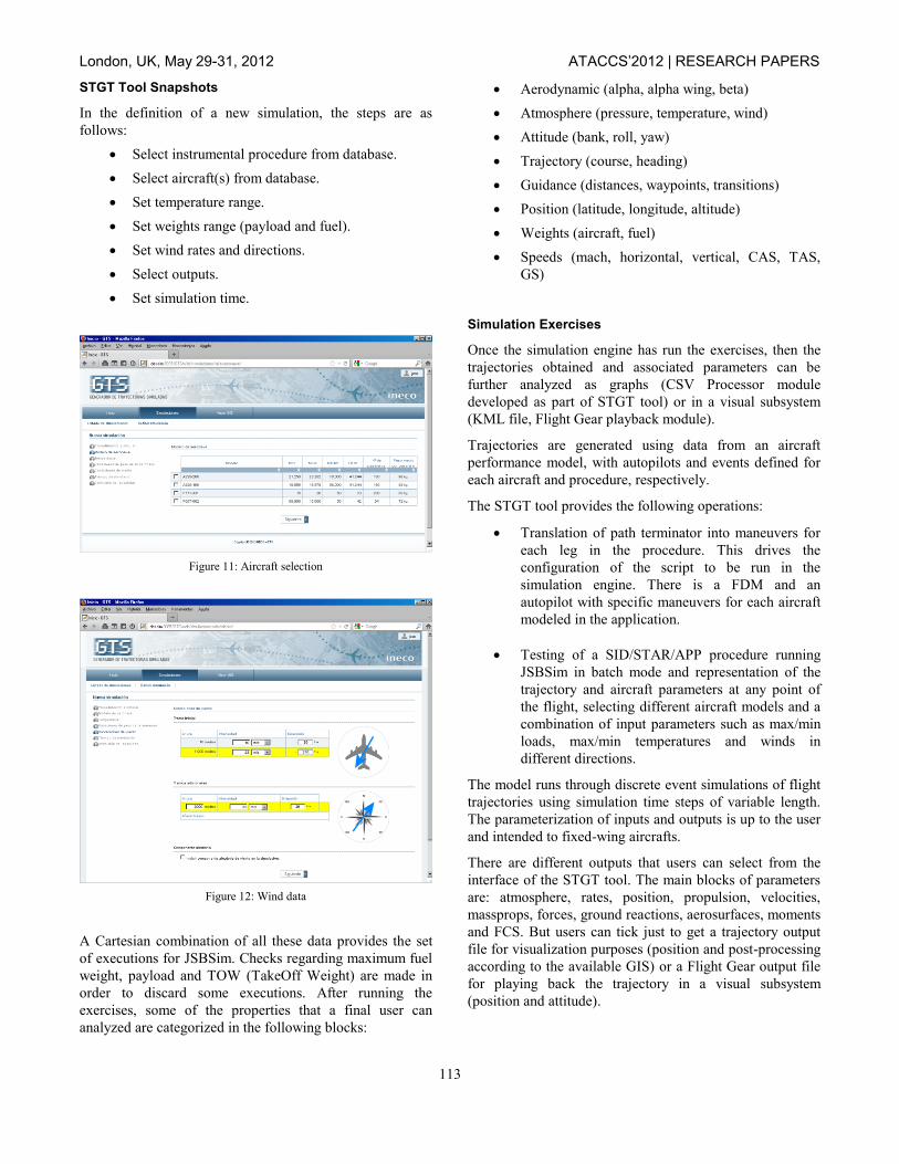
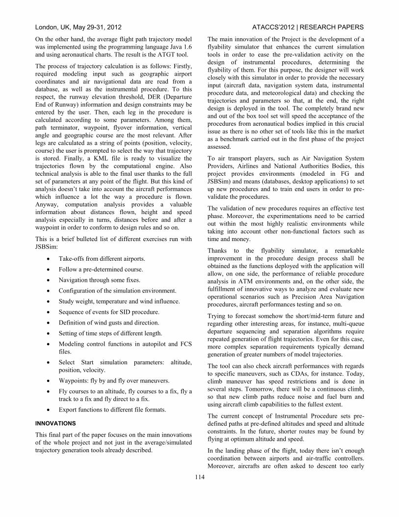
STGT Tool Snapshots
In the definition of a new simulation, the steps are as
follows:
Select instrumental procedure from database.
Select aircraft(s) from database.
Set temperature range.
Set weights range (payload and fuel).
Set wind rates and directions.
Select outputs.
Set simulation time.
Figure 11: Aircraft selection
Figure 12: Wind data
A Cartesian combination of all these data provides the set
of executions for JSBSim. Checks regarding maximum fuel
weight, payload and TOW (TakeOff Weight) are made in
order to discard some executions. After running the
exercises, some of the properties that a final user can
analyzed are categorized in the following blocks:
Aerodynamic (alpha, alpha wing, beta)
Atmosphere (pressure, temperature, wind)
Attitude (bank, roll, yaw)
Trajectory (course, heading)
Guidance (distances, waypoints, transitions)
Position (latitude, longitude, altitude)
Weights (aircraft, fuel)
Speeds (mach, horizontal, vertical, CAS, TAS,
GS)
Simulation Exercises
Once the simulation engine has run the exercises, then the
trajectories obtained and associated parameters can be
further analyzed as graphs (CSV Processor module
developed as part of STGT tool) or in a visual subsystem
(KML file, Flight Gear playback module).
Trajectories are generated using data from an aircraft
performance model, with autopilots and events defined for
each aircraft and procedure, respectively.
The STGT tool provides the following operations:
Translation of path terminator into maneuvers for
each leg in the procedure. This drives the
configuration of the script to be run in the
simulation engine. There is a FDM and an
autopilot with specific maneuvers for each aircraft
modeled in the application.
Testing of a SID/STAR/APP procedure running
JSBSim in batch mode and representation of the
trajectory and aircraft parameters at any point of
the flight, selecting different aircraft models and a
combination of input parameters such as max/min
loads, max/min temperatures and winds in
different directions.
The model runs through discrete event simulations of flight
trajectories using simulation time steps of variable length.
The parameterization of inputs and outputs is up to the user
and intended to fixed-wing aircrafts.
There are different outputs that users can select from the
interface of the STGT tool. The main blocks of parameters
are: atmosphere, rates, position, propulsion, velocities,
massprops, forces, ground reactions, aerosurfaces, moments
and FCS. But users can tick just to get a trajectory output
file for visualization purposes (position and post-processing
according to the available GIS) or a Flight Gear output file
for playing back the trajectory in a visual subsystem
(position and attitude).
London, UK, May 29-31, 2012 ATACCS’2012 | RESEARCH PAPERS
114
On the other hand, the average flight path trajectory model
was implemented using the programming language Java 1.6
and using aeronautical charts. The result is the ATGT tool.
The process of trajectory calculation is as follows: Firstly,
required modeling input such as geographic airport
coordinates and air navigational data are read from a
database, as well as the instrumental procedure. To this
respect, the runway elevation threshold, DER (Departure
End of Runway) information and design constraints may be
entered by the user. Then, each leg in the procedure is
calculated according to some parameters. Among them,
path terminator, waypoint, flyover information, vertical
angle and geographic course are the most relevant. After
legs are calculated as a string of points (position, velocity,
course) the user is prompted to select the way that trajectory
is stored. Finally, a KML file is ready to visualize the
trajectories flown by the computational engine. Also
technical analysis is able to the final user thanks to the full
set of parameters at any point of the flight. But this kind of
analysis doesn’t take into account the aircraft performances
which influence a lot the way a procedure is flown.
Anyway, computation analysis provides a valuable
information about distances flown, height and speed
analysis especially in turns, distances before and after a
waypoint in order to conform to design rules and so on.
This is a brief bulleted list of different exercises run with
JSBSim:
Take-offs from different airports.
Follow a pre-determined course.
Navigation through some fixes.
Configuration of the simulation environment.
Study weight, temperature and wind influence.
Sequence of events for SID procedure.
Definition of wind gusts and direction.
Setting of time steps of different length.
Modeling control functions in autopilot and FCS
files.
Select Start simulation parameters: altitude,
position, velocity.
Waypoints: fly by and fly over maneuvers.
Fly courses to an altitude, fly courses to a fix, fly a
track to a fix and fly direct to a fix.
Export functions to different file formats.
INNOVATIONS
This final part of the paper focuses on the main innovations
of the whole project and not just in the average/simulated
trajectory generation tools already described.
The main innovation of the Project is the development of a
flyability simulator that enhances the current simulation
tools in order to ease the pre-validation activity on the
design of instrumental procedures, determining the
flyability of them. For this purpose, the designer will work
closely with this simulator in order to provide the necessary
input (aircraft data, navigation system data, instrumental
procedure data, and meteorological data) and checking the
trajectories and parameters so that, at the end, the right
design is deployed in the tool. The completely brand new
and out of the box tool set will speed the acceptance of the
procedures from aeronautical bodies implied in this crucial
issue as there is no other set of tools like this in the market
as a benchmark carried out in the first phase of the project
assessed.
To air transport players, such as Air Navigation System
Providers, Airlines and National Authorities Bodies, this
project provides environments (modeled in FG and
JSBSim) and means (databases, desktop applications) to set
up new procedures and to train end users in order to pre-
validate the procedures.
The validation of new procedures requires an effective test
phase. Moreover, the experimentations need to be carried
out within the most highly realistic environments while
taking into account other non-functional factors such as
time and money.
Thanks to the flyability simulator, a remarkable
improvement in the procedure design process shall be
obtained as the functions deployed with the application will
allow, on one side, the performance of reliable procedure
analysis in ATM environments and, on the other side, the
fulfillment of innovative ways to analyze and evaluate new
operational scenarios such as Precision Area Navigation
procedures, aircraft performances testing and so on.
Trying to forecast somehow the short/mid-term future and
regarding other interesting areas, for instance, multi-queue
departure sequencing and separation algorithms require
repeated generation of flight trajectories. Even for this case,
more complex separation requirements typically demand
generation of greater numbers of model trajectories.
The tool can also check aircraft performances with regards
to specific maneuvers, such as CDAs, for instance. Today,
climb maneuver has speed restrictions and is done in
several steps. Tomorrow, there will be a continuous climb,
so that new climb paths reduce noise and fuel burn and
using aircraft climb capabilities to the fullest extent.
The current concept of Instrumental Procedure sets pre-
defined paths at pre-defined altitudes and speed and altitude
constraints. In the future, shorter routes may be found by
flying at optimum altitude and speed.
In the landing phase of the flight, today there isn’t enough
coordination between airports and air-traffic controllers.
Moreover, aircrafts are often asked to descent too early

London, UK, May 29-31, 2012 ATACCS’2012 | RESEARCH PAPERS
115
and/or put on holding. There are also pre-set speeds and
stepped routes. On the contrary, the continuous descend
approach is growing as it uses the aircraft gliding
capabilities to the fullest extent, allowing for higher
precision landings and lower noise impact.
The architecture of this tool is highly modular and flexible
to deal with new requirements from SESAR [6] (Single
European Sky ATM Research) and/or NextGen [7]
initiative programmes.
The visualization tool allows the analysis of different
trajectory data sources, including radar data, simulated
trajectories and computed/average trajectories.
Interoperability is also a concern in the project but it
requires internationally agreed standards and, for that,
SESAR will deliver the technical basis for defining them
through ICAO (International Civil Aviation Organization)
SARPs (Standards and Recommended Practices) and other
coordinated industry standards as AIXM [8] for data. The
foreseen breakthroughs in this field are explained next.
ENHANCEMENTS
Platform Interoperability
The main lines in interoperability foreseen in this project
are:
Connection with simulation platforms where
simulated traffic can validate new control
techniques. The Flyability Simulator shall adjust to
the simulated traffic needs of those platforms. In
this sense, there are ongoing works in SESAR
initiative whose goals refer to validation of
advanced operational concepts.
Gate-to-Gate concept. Today information managed
by ATC systems is not shared. So, ATC
constraints the trajectory. In the future, ATM
communication network will connect different
systems so that flights are managed as a
continuous event from planning through execution.
The Flyability Simulator shall analyze the cross-
implications of getting together disparate actors in
one environment.
Connection with tools used in environmental
impact studies such as noise and gas emissions. To
this respect, the collaboration with ongoing
European projects shall consist in the analysis of
different input sources such as in-flight reports,
flight plans, FOQA data, flight schedule, radar and
wind data, pilots and ATC feedback, AIP, then
apply some validation criteria and quality checks
to populate a database in order to run assessments
(statistical operations, calculations, graphics),
filtering criteria (RNP value and deviation from
horizontal route, vertical RNP and deviation from
the vertical path, analysis of CDAs) and obtain key
indicators (deviation of parameters among
profiles, fuel flow and fuel burn, number of lost
opportunities against time).
Connection with Green ATM lines: Measure noise
and fuel burn in order to test new procedures and
generate greener trajectories. In this sense, the
Flyability Simulator shall be flexible enough to
work with new ATM scenarios.
Optimization
It shall be studied the connection with flight planning
system in order to produce optimized route based on
different factors:
Economic criteria (cost index ratio, for instance)
Accurate data (make comparisons with real data,
for instance)
Add constraints (flight time, for instance). Flight
time is computed taken into account ground speed
and ground distance and it is the sum of all the
segments measured between WPs and expressed in
NM (nautical miles).
Real flight profiles (validate computed/simulated
trajectories, for instance). There has been a line of
work to validate simulations against Flight Data
Records in cooperation with UPM University.
The Simulator shall study and link flight operations with
flight planning, and aircraft performance and routes. We
focused on the route side, but it could be improved trying to
get an optimum one, checking speed, distance, wind
conditions and commercial schedule.
Then, some estimation based on well-known indicators
could be derived. For instance, estimated elapsed flight
time (EET) is important as it specifies how long the aircraft
engine will be running and therefore how much fuel will be
consumed. This indicator is related with optimum flight
operations. Up to now, simple engine modeling and just
impact of weight were taken into account in our studies.
It’s known that the two variables that most influence fuel
consumption are cruise speed and cruise altitude. As the
Flyability Simulator focuses primarily in SID and
STAR/APP procedures, the impact of fuel consumed was
not considered. But, on the other hand, neither noise values
nor gas emissions are measured although they are more
critical in the aforementioned flight phases. Finally, the
project does not optimize the specific range as drag cannot
be minimized in order to get the aircraft fly at the optimum
altitude in departure and arrival procedures.
This list of enhancements and interoperability lines were
reported in a deliverable in the project and could be the
seed for future developments.
London, UK, May 29-31, 2012 ATACCS’2012 | RESEARCH PAPERS
116
In the short term, following steps in this project ought to
focus on trying to implement more advanced controllers
that would allow us to achieve a better performance with a
wider range of aircrafts. We can conclude that modeling
and simulating a commercial aircraft accurately is not an
easy task, due to the need to calculate many parameters
either by physical measurements or estimation from
available data such as FDR.
CONCLUSION
This paper focused on the flight trajectory generation tools
available within the Flyability Simulator project,
documenting a method for generation of aircraft flyable
trajectories based on an open-source simulation engine. A
comparison between average flight computation and
simulated trajectories generation was shown. From a study
of different simulation engines, we conclude that JSBSim
has proven to be useful in flight simulation applications
such as this project.
An algorithm has been developed to convert procedure
charts into scripts and later, run them with a simulation
engine. Also, commercial aircrafts have been modeled and
their Flight Dynamics Model and Flight Control System are
provided.
From the viewpoint of testing, meteorological conditions
can be modified and are user-configurable, as well as
simulation start conditions (Start altitude/Start
position/Flight level/Velocities and angles and so on).
Finally, trajectories either from calculation or simulation
can be compared so that an instrumental procedure under
design may speed up the ground validation phase.
REFERENCES
1. “A Flight Trajectory Generator For a PC-based
Analysis Tool”: paper presented in ATACCS 2011 by
Jaime García Sáez
2. JSBSim aircraft flight model:
http://jsbsim.sourceforge.net
3. FlightGear Autopilot: Theory, Configuration, and
Tuning: http://www.flightgear.org/Docs/XMLAutopilot
4. Aeromatic:
http://jsbsim.sourceforge.net/aeromatic.html
5. ICAO: http://www.icao.int
6. SESAR JU: http://www.sesarju.eu
7. NextGen: http://www.faa.gov/nextgen
8. AIXM: http://www.aixm.aero
9. FPDAM: http://www.idscompany.it
10. Softrack: http://gina.infra.upm.es/wp/com/pat.html


