

Single PhaseInduction Motor
Dr Sanjay Jain
Department Of EEEX
Application - The single-phase induction machine is
the most frequently used motor for refrigerators
washing machines clocks drills compressors
pumps and etc
1048707
The single-phase motor stator has a laminated iron
core with two windings arranged perpendicularly
1 One is the main and
2 The other is the auxiliary winding or starting
winding
The single-phase induction motor operation
can be described by two methods
ndash Double revolving field theory and
ndash Cross-field theory
bull Double revolving theory is perhaps the
easier of the two explanations to understand
bull Learn the double revolving theory only
Double revolving field theory
bull A single-phase ac current supplies the main
winding that produces a pulsating magnetic
field
bull Mathematically the pulsating field could be
divided into two fields which are rotating in
opposite directions
bull The interaction between the fields and the
current induced in the rotor bars generates
opposing torque
Double revolving field theory
bull Each of the rotating fields induces a voltage in the
rotor which drives current and produces torque
bull An equivalent circuit similar to the equivalent
circuit of a three phase motor can represent each
field
bull The parameters of the two circuits are the same
with the exception of the slip
Double revolving field theory
bull The two equivalent circuits are connected in series
bull Fig shows the equivalent circuit of a singlephase
motor in running condition
bull The current power and torque can be calculated
from the combined equivalent circuit using the Ohm
Law
bull The calculations are demonstrated on a numerical
example
AC Motorbull An AC motor is an electric motor driven by an alternating current (AC)
Types of AC Motor [depending on the type of rotor used]
1 The first type is the induction motor or asynchronous motor
This type relies on a small difference in speed between the rotating magnetic field and the rotor to induce rotor current
2The second type is the synchronous motor
This type does not rely on induction and as a result can rotate exactly at the supply frequency or a sub-multiple of the supply frequency
Types of Single Phase Motors Are[construction amp method of starting]These motors are designed to operate from single phase supply are manufactured in large no of types for the use in home offices factories etc small motors come in Kilo Watt power ratings
bull Induction Motors
bull Repulsion Motors
bull AC Series Motors
bull Un-exited Synchronous Motors
Double Revolving Field Theory
1 If the rotor is given an initial rotation in either direction the torque due to the rotating field acting in the direction of initial rotation coil will be more than that due to the other rotating field and the motor will develop a net positive torque in the same direction as the initial rotation
2 Thus the motor will keep running in the direction of initial rotation3 According to this theory any alternating quantity can be resolved into
two rotating components which rotate in opposite directions and each having magnitude as half of the maximum magnitude of the alternating quantity
3In case of single phase induction motors the stator winding produces an alternating magnetic field having maximum magnitude of Φ1m
4According to double revolving field theory consider the two components of the stator flux each having magnitude half of maximum magnitude of stator flux ie (Φ1m2)
5 Both these components are rotating in opposite directions at the synchronous speed Ns which is dependent on frequency and stator poles
bull Let Φf is forward component rotating in anticlockwise direction
bull while Φb is the backward component rotating in clockwise direction
bull The resultant of these two components at any instant gives the instantaneous value of the stator flux at the instant
bull So resultant of these two is the original stator flux
fig shows the stator flux and its two components Φf and Φb At start both the components are shown opposite to each other in the Fig1(a) Thus the resultant ΦR = 0 This is nothing but the instantaneous value of the stator flux at start After 90o as shown in the Fig 1(b) the two components are rotated in such a way that both are pointing in the same direction
Hence the resultant ΦR is the algebraic sum of the magnitudes of the two components So ΦR = (Φ1m2) + (Φ1m2) =Φ1m This is nothing but the instantaneous value of the stator flux at θ = 90o as shown in the Fig 1(c) Thus continuous rotation of the two components gives the original alternating stator flux
bull Both the components are rotating and hence get cut by the motor conductors
bull Due to cutting of flux emf gets induced in rotor which circulates rotor current
bull The rotor current produces rotor flux
bull This flux interacts with forward component Φf to produce a torque in one particular direction say anticlockwise direction
bull While rotor flux interacts with backward component Φb to produce a torque in the clockwise direction
bull So if anticlockwise torque is positive then clockwise torque is negative
At start these two torque are equal in magnitude but
opposite in direction
Each torque tries to rotate the rotor in its own
direction
Thus net torque experienced by the rotor is zero at
start And hence the single phase induction motors
are not self starting
Torque speed characteristicsbull The two oppositely directed torques and the resultant torque can be shown effectively
with the help of torque-speed characteristics
Starting methods
o single-phase capacitor-start motors
o capacitor-run motors
osplit-phase motors
o shaded-pole motors
o small poly phase induction motors
Single Phase Induction Motor
bull The single-phase motor starting torque is zero
because of the pulsating single-phase magnetic flux
bull The starting of the motor requires the generation of a
rotating magnetic flux similar to the rotating flux in
a three-phase motor
bull Two perpendicular coils that have currents 90deg outof-
phase can generate the necessary rotating
magnetic fields which start the motor
bull Therefore single-phase motors are built with two
perpendicular windings
The phase shift is achieved by
connecting
ndash a resistance
ndash an inductance or
ndash a capacitance
in series with the starting winding
bull Most frequently used is a capacitor to
generate the starting torque
Capacitor start induction motor
Capacitor run motors
Split phase motor
Shaded pole motors
Blocked Rotor test for Induction Motorbull Blocked rotor test is conducted on an induction motor It is also known as short circuit test or
locked rotor test or stalled torque test
bull From this test short circuit current at normal voltage power factor on short circuit total leakage reactance starting torque of the motor can be found
bull The test is conducted at low voltage because if the applied voltage was normal voltage then the current flowing through the stator windings were high enough to over heat the winding and damage them
bull The blocked rotor torque test is not performed on a wound rotor motors because the starting torque can be varied as desired However blocked rotor current test is conducted on squirrel cage rotor motors
some one can hold this shaft to block the rotation
0-10A
0-300V
Method
bull In the blocked rotor test the rotor is locked
bull A low voltage is applied on the stator terminals so that full load current flows in the stator winding
bull The current voltage and power input are measured at this point
bull When the rotor is stationary the slip S=1
bull The test is conducted at 14th the rated frequency as recommended by IEEE
bull This is because the rotors effective resistance at low frequency may differ at high frequency
bull The test can be repeated for different values of voltage to ensure the values obtained are consistent
bull As the current flowing through the stator may exceed the rated current the test should be conducted quickly
bull By using the parameters found by this test the motor circle diagram can be constructed
No Load Test of Induction Motorbull By the name no load test it means that there is no load- that is load is zero But it is exact
opposite No load means infinite load test It is because in no load there is NO load and no load means it is open circuit Open circuit means infinite resistance
bull But that was the case in transformers where you can open circuit the low voltage of transformer and obtain readings But how will you do that in Induction motor How can you make infinite resistance at load side
bull If slip=0 then Rl will be infinite And you can make slip zero by making synchronous speed Ns equal to actual speed N
bull So slip will be zero Load resistance will be infinite
No load at output of motor0-300V
0-10A
Method
bull Connect the circuit
bull Supply the rated voltage to induction motor keep it running
bull The current drawn by motor is quit low
bull Take care of the voltmeter should be of voltage ratings of induction motor amp the ratings of ammeter should be low because the current drawn by motor is very small
bull Take the readings of voltmeter ammeter and wattmeter

Double revolving field theory
bull The two equivalent circuits are connected in series
bull Fig shows the equivalent circuit of a singlephase
motor in running condition
bull The current power and torque can be calculated
from the combined equivalent circuit using the Ohm
Law
bull The calculations are demonstrated on a numerical
example
AC Motorbull An AC motor is an electric motor driven by an alternating current (AC)
Types of AC Motor [depending on the type of rotor used]
1 The first type is the induction motor or asynchronous motor
This type relies on a small difference in speed between the rotating magnetic field and the rotor to induce rotor current
2The second type is the synchronous motor
This type does not rely on induction and as a result can rotate exactly at the supply frequency or a sub-multiple of the supply frequency
Types of Single Phase Motors Are[construction amp method of starting]These motors are designed to operate from single phase supply are manufactured in large no of types for the use in home offices factories etc small motors come in Kilo Watt power ratings
bull Induction Motors
bull Repulsion Motors
bull AC Series Motors
bull Un-exited Synchronous Motors
Double Revolving Field Theory
1 If the rotor is given an initial rotation in either direction the torque due to the rotating field acting in the direction of initial rotation coil will be more than that due to the other rotating field and the motor will develop a net positive torque in the same direction as the initial rotation
2 Thus the motor will keep running in the direction of initial rotation3 According to this theory any alternating quantity can be resolved into
two rotating components which rotate in opposite directions and each having magnitude as half of the maximum magnitude of the alternating quantity
3In case of single phase induction motors the stator winding produces an alternating magnetic field having maximum magnitude of Φ1m
4According to double revolving field theory consider the two components of the stator flux each having magnitude half of maximum magnitude of stator flux ie (Φ1m2)
5 Both these components are rotating in opposite directions at the synchronous speed Ns which is dependent on frequency and stator poles
bull Let Φf is forward component rotating in anticlockwise direction
bull while Φb is the backward component rotating in clockwise direction
bull The resultant of these two components at any instant gives the instantaneous value of the stator flux at the instant
bull So resultant of these two is the original stator flux
fig shows the stator flux and its two components Φf and Φb At start both the components are shown opposite to each other in the Fig1(a) Thus the resultant ΦR = 0 This is nothing but the instantaneous value of the stator flux at start After 90o as shown in the Fig 1(b) the two components are rotated in such a way that both are pointing in the same direction
Hence the resultant ΦR is the algebraic sum of the magnitudes of the two components So ΦR = (Φ1m2) + (Φ1m2) =Φ1m This is nothing but the instantaneous value of the stator flux at θ = 90o as shown in the Fig 1(c) Thus continuous rotation of the two components gives the original alternating stator flux
bull Both the components are rotating and hence get cut by the motor conductors
bull Due to cutting of flux emf gets induced in rotor which circulates rotor current
bull The rotor current produces rotor flux
bull This flux interacts with forward component Φf to produce a torque in one particular direction say anticlockwise direction
bull While rotor flux interacts with backward component Φb to produce a torque in the clockwise direction
bull So if anticlockwise torque is positive then clockwise torque is negative
At start these two torque are equal in magnitude but
opposite in direction
Each torque tries to rotate the rotor in its own
direction
Thus net torque experienced by the rotor is zero at
start And hence the single phase induction motors
are not self starting
Torque speed characteristicsbull The two oppositely directed torques and the resultant torque can be shown effectively
with the help of torque-speed characteristics
Starting methods
o single-phase capacitor-start motors
o capacitor-run motors
osplit-phase motors
o shaded-pole motors
o small poly phase induction motors
Single Phase Induction Motor
bull The single-phase motor starting torque is zero
because of the pulsating single-phase magnetic flux
bull The starting of the motor requires the generation of a
rotating magnetic flux similar to the rotating flux in
a three-phase motor
bull Two perpendicular coils that have currents 90deg outof-
phase can generate the necessary rotating
magnetic fields which start the motor
bull Therefore single-phase motors are built with two
perpendicular windings
The phase shift is achieved by
connecting
ndash a resistance
ndash an inductance or
ndash a capacitance
in series with the starting winding
bull Most frequently used is a capacitor to
generate the starting torque
Capacitor start induction motor
Capacitor run motors
Split phase motor
Shaded pole motors
Blocked Rotor test for Induction Motorbull Blocked rotor test is conducted on an induction motor It is also known as short circuit test or
locked rotor test or stalled torque test
bull From this test short circuit current at normal voltage power factor on short circuit total leakage reactance starting torque of the motor can be found
bull The test is conducted at low voltage because if the applied voltage was normal voltage then the current flowing through the stator windings were high enough to over heat the winding and damage them
bull The blocked rotor torque test is not performed on a wound rotor motors because the starting torque can be varied as desired However blocked rotor current test is conducted on squirrel cage rotor motors
some one can hold this shaft to block the rotation
0-10A
0-300V
Method
bull In the blocked rotor test the rotor is locked
bull A low voltage is applied on the stator terminals so that full load current flows in the stator winding
bull The current voltage and power input are measured at this point
bull When the rotor is stationary the slip S=1
bull The test is conducted at 14th the rated frequency as recommended by IEEE
bull This is because the rotors effective resistance at low frequency may differ at high frequency
bull The test can be repeated for different values of voltage to ensure the values obtained are consistent
bull As the current flowing through the stator may exceed the rated current the test should be conducted quickly
bull By using the parameters found by this test the motor circle diagram can be constructed
No Load Test of Induction Motorbull By the name no load test it means that there is no load- that is load is zero But it is exact
opposite No load means infinite load test It is because in no load there is NO load and no load means it is open circuit Open circuit means infinite resistance
bull But that was the case in transformers where you can open circuit the low voltage of transformer and obtain readings But how will you do that in Induction motor How can you make infinite resistance at load side
bull If slip=0 then Rl will be infinite And you can make slip zero by making synchronous speed Ns equal to actual speed N
bull So slip will be zero Load resistance will be infinite
No load at output of motor0-300V
0-10A
Method
bull Connect the circuit
bull Supply the rated voltage to induction motor keep it running
bull The current drawn by motor is quit low
bull Take care of the voltmeter should be of voltage ratings of induction motor amp the ratings of ammeter should be low because the current drawn by motor is very small
bull Take the readings of voltmeter ammeter and wattmeter
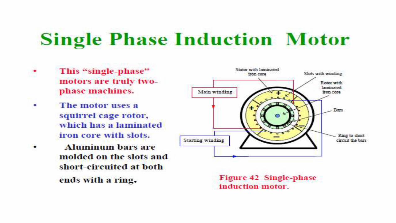
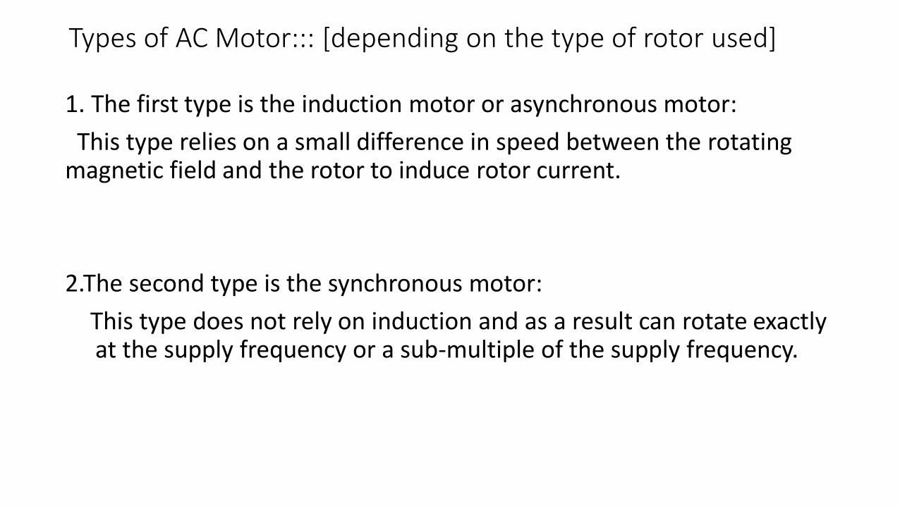
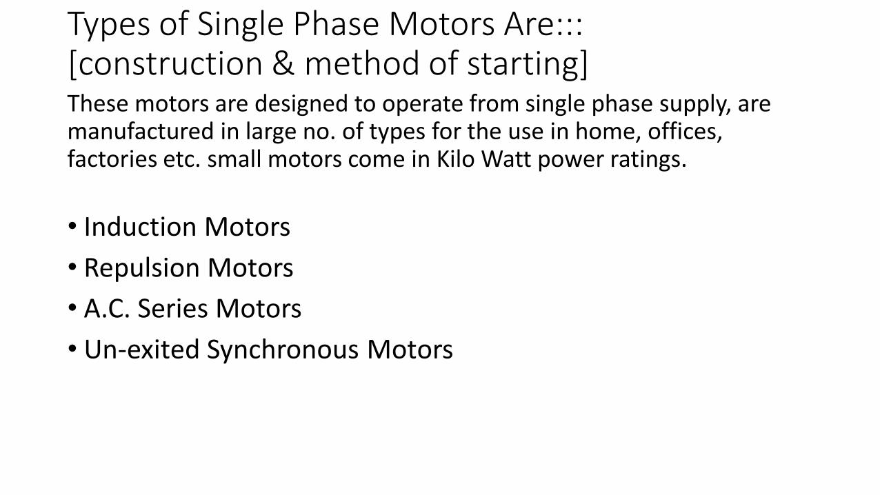

Method
bull In the blocked rotor test the rotor is locked
bull A low voltage is applied on the stator terminals so that full load current flows in the stator winding
bull The current voltage and power input are measured at this point
bull When the rotor is stationary the slip S=1
bull The test is conducted at 14th the rated frequency as recommended by IEEE
bull This is because the rotors effective resistance at low frequency may differ at high frequency
bull The test can be repeated for different values of voltage to ensure the values obtained are consistent
bull As the current flowing through the stator may exceed the rated current the test should be conducted quickly
bull By using the parameters found by this test the motor circle diagram can be constructed
No Load Test of Induction Motorbull By the name no load test it means that there is no load- that is load is zero But it is exact
opposite No load means infinite load test It is because in no load there is NO load and no load means it is open circuit Open circuit means infinite resistance
bull But that was the case in transformers where you can open circuit the low voltage of transformer and obtain readings But how will you do that in Induction motor How can you make infinite resistance at load side
bull If slip=0 then Rl will be infinite And you can make slip zero by making synchronous speed Ns equal to actual speed N
bull So slip will be zero Load resistance will be infinite
No load at output of motor0-300V
0-10A
Method
bull Connect the circuit
bull Supply the rated voltage to induction motor keep it running
bull The current drawn by motor is quit low
bull Take care of the voltmeter should be of voltage ratings of induction motor amp the ratings of ammeter should be low because the current drawn by motor is very small
bull Take the readings of voltmeter ammeter and wattmeter


